Embed Size (px)
Citation preview

Block-in-matrix structure –tunneling in hard soil and/or weak rock
Structure blocs-en-matrice – construction detunnels dans les sols indurés et/ou les roches tendres
D. Adam1
Vienna University of Technology, Institute for Geotechnics Geotechnik Adam ZT GmbH, Austria
R. MarkiewiczGeotechnik Adam ZT GmbH, Austria
M. BrunnerAuthority of Lower Austrian Government, Austria
ABSTRACT
The city bypass tunnel of Waidhofen an der Ybbs (Austria) is situated in an intricate geological-geotechnical complex consistingof soil, hard soil, weak rock and solid rock. Marls and marly limestone (Waidhofener formation) predominate followed by tec-tonic breccia of the Alpine cliff zone, which is a tectonic melange zone. Materials of this kind universally have isolated interiorblocks (shaded areas) embedded in a matrix (blank area) called “block-in-matrix” requiring a particular characterization of the mechanical rock mass properties. The complex geological and morphological situation required the application of various tunne-ling methods including open cuts, cut-and-cover sections and the New Austrian Tunneling Method (NATM). During construc-tion in creeping slopes increased movements were triggered, which required the installation of a sophisticated monitoring sys-tem. On the basis of monitoring data and additional ground investigations structural measures were assessed that enabled safetunneling in the creeping slope.
RÉSUMÉ
Le tunnel urbain de Waidhofen an der Ybbs (Autriche) est situé dans un mélange complexe géologique-géotechnique compre-nant des sols, des sols indurés, des roches tendres et des roches solides. Les marnes et les marno-calcaires (formation de Waidho-fen) dominent, suivis par des brèches («breccia») tectoniques de la zone d'escarpement alpin, qui est une zone de mélange tecto-nique. Les matériaux de cette nature comprennent toujours des blocs isolés (surfaces ombrées) insérés dans une matrice (surface blanche) et sont appelés «blocs-en-matrice». Ils requièrent une caractérisation particulière des propriétés de la masse rocheuse. La situation géologique et morphologique complexe a nécessité l’application de diverses méthodes de construction de tunnels,comprenant des tranchées ouvertes, des tranchées couvertes, ainsi que la Nouvelle Méthode Autrichienne (NATM). Durant la construction dans des pentes en mouvement lent, des déplacements accrus ont été déclenchés, ce qui a nécessité l’installationd’un système de suivi sophistiqué. Sur la base de données du suivi et de reconnaissances des terrains additionnelles, des mesures structurelles ont été évaluées et ont permis de creuser avec sécurité dans ces pentes.
Keywords: Tunneling, NATM, creeping slope, hard soil, weak rock, block-in-matrix, bimrock
1 Corresponding Author.
1 PROJECT
The city tunnel Waidhofen an der Ybbs is thecore of the city by-pass of a small town of the same name in the south-west of Lower Austria. The road tunnel comprising a total length of
1,485 m is situated along the mountain ridge called Buchenberg and the maximum overburden of the tunnel is about 50 m. Tunnel construction started in November 2007 whereby different construction techniques were applied. The open-ing to traffic is planned in the end of 2011.
Proceedings of the 15th European Conference on Soil Mechanics and Geotechnical EngineeringA. Anagnostopoulos et al. (Eds.)IOS Press, 2011© 2011 The authors and IOS Press. All rights reserved.doi:10.3233/978-1-60750-801-4-1607
1607
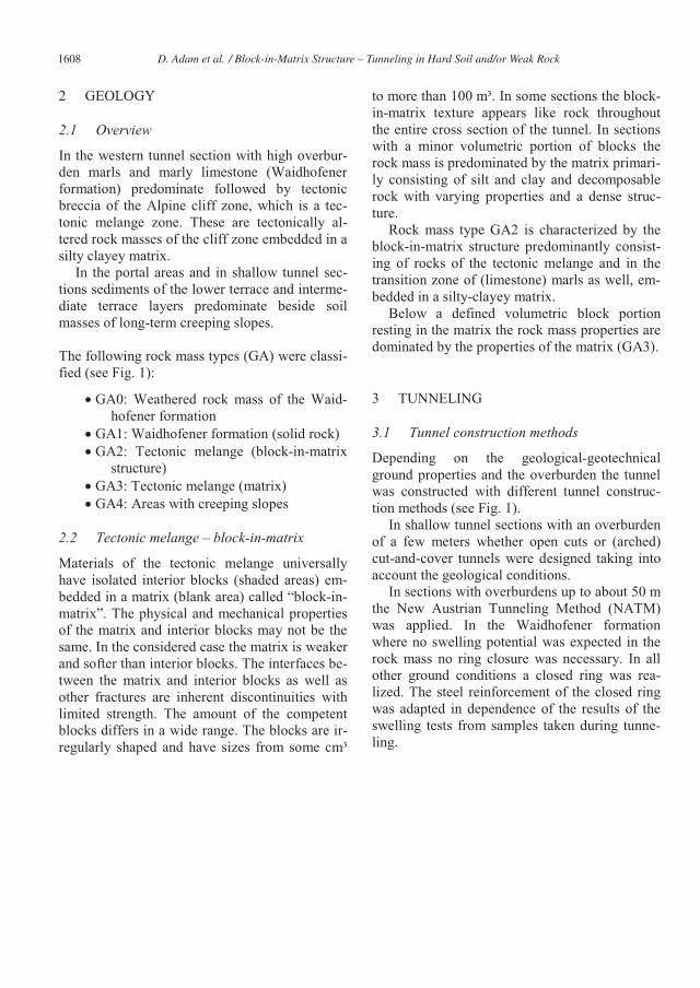
2 GEOLOGY
2.1 Overview
In the western tunnel section with high overbur-den marls and marly limestone (Waidhofener formation) predominate followed by tectonic breccia of the Alpine cliff zone, which is a tec-tonic melange zone. These are tectonically al-tered rock masses of the cliff zone embedded in a silty clayey matrix.
In the portal areas and in shallow tunnel sec-tions sediments of the lower terrace and interme-diate terrace layers predominate beside soil masses of long-term creeping slopes.
The following rock mass types (GA) were classi-fied (see Fig. 1):
� GA0: Weathered rock mass of the Waid-hofener formation
� GA1: Waidhofener formation (solid rock)� GA2: Tectonic melange (block-in-matrix
structure)� GA3: Tectonic melange (matrix)� GA4: Areas with creeping slopes
2.2 Tectonic melange – block-in-matrix
Materials of the tectonic melange universally have isolated interior blocks (shaded areas) em-bedded in a matrix (blank area) called “block-in-matrix”. The physical and mechanical properties of the matrix and interior blocks may not be the same. In the considered case the matrix is weaker and softer than interior blocks. The interfaces be-tween the matrix and interior blocks as well as other fractures are inherent discontinuities with limited strength. The amount of the competent blocks differs in a wide range. The blocks are ir-regularly shaped and have sizes from some cm³
to more than 100 m³. In some sections the block-in-matrix texture appears like rock throughout the entire cross section of the tunnel. In sections with a minor volumetric portion of blocks the rock mass is predominated by the matrix primari-ly consisting of silt and clay and decomposable rock with varying properties and a dense struc-ture.
Rock mass type GA2 is characterized by the block-in-matrix structure predominantly consist-ing of rocks of the tectonic melange and in the transition zone of (limestone) marls as well, em-bedded in a silty-clayey matrix.
Below a defined volumetric block portion resting in the matrix the rock mass properties are dominated by the properties of the matrix (GA3).
3 TUNNELING
3.1 Tunnel construction methods
Depending on the geological-geotechnical ground properties and the overburden the tunnel was constructed with different tunnel construc-tion methods (see Fig. 1).
In shallow tunnel sections with an overburden of a few meters whether open cuts or (arched) cut-and-cover tunnels were designed taking into account the geological conditions.
In sections with overburdens up to about 50 mthe New Austrian Tunneling Method (NATM)was applied. In the Waidhofener formation where no swelling potential was expected in the rock mass no ring closure was necessary. In all other ground conditions a closed ring was rea-lized. The steel reinforcement of the closed ring was adapted in dependence of the results of the swelling tests from samples taken during tunne-ling.
D. Adam et al. / Block-in-Matrix Structure – Tunneling in Hard Soil and/or Weak Rock1608

NATM was combined with blasting within the Waidhofener formation whereby the defined vi-bration limit values had not to be exceeded due to the vicinity of the inhabited area. In the other rock masses excavation took place with hydrau-lic excavation equipment with light blasting if necessary.
In the central area where the tunnel was si-tuated above the ground surface a rectangular open tunnel was designed.
Between the open cut and the NATM section the cut-and-cover method with an arched ceiling was applied.
In the portal sections the tunnel was con-structed in open cuts.
4 BLOCK IN MATRIX
4.1 Definition
The term “bimrock” or “block-in-matrix rocks” describes mixtures of rocks composed of geo-technical significant blocks within a bonded ma-trix of finer texture. The tectonic melange zone (GA2 and GA3) complies with this definition.
The words geotechnical significant in the above definition of bimrocks mean that there are criteria for scale, strength contrast, proportion and size of blocks. In bimrocks blocks must have mechanical contrast with the matrix and at the scale of engineering interest there must be enough blocks of a certain size range to contri-bute to the overall strength of the rock mass meeting the following criteria:
Figure 1. Tunnel alignment in the project area and geological longitudinal section with different tunneling methods. In the ground plan the areas with creeping slopes are shown.
D. Adam et al. / Block-in-Matrix Structure – Tunneling in Hard Soil and/or Weak Rock 1609
� Significant variation of mechanical beha-vior between blocks and matrix with re-spect to friction angle, strength, etc.
� Significant scale factor between block size and the so called characteristic dimen-sion, in this case the tunnel diameter. The upper limit for the block size is de-fined with 75% and the lower limit with 5% of the tunnel diameter. Beyond this value the ground is designated rock, be-low matrix (soil).
� If the volumetric portion is between 25 and 75% the rock mass is classified as bi-mrock. It is assumed that the linearly determined block portion from bore-holes complies with the volumetric block portion and thus coincides with the spatial distribution within the ma-trix.
Following the definition of bimrock the decisive block size d was derived from the tunnel diame-ter of 10 m to:
� M����ÃÒ!�\���� B���{Ò\����!� ���� Sound rock: 7,���!
The differentiation between matrix and bimrock was defined with a volumetric block portion of 30%. With a block portion of <30% the rock mass behavior is predominated by the matrix and the stiffness and strength parameters etc. are de-rived from the matrix (GA3). The rock mass classified GA2 is defined by a block portion of >30% and is determined from the bimrock theory.
4.2 Rock mass behavior
The soil mechanical properties of a bimrock structure can be concluded as follows [2]:
The overall stiffness of a tectonic melange in-creases with an increasing block portion. How-ever, the stiffness modulus of the entire melange mass is conservatively assessed in accordance with the stiffness of the matrix on the safe side.
The cohesion of the tectonic melange decreas-es with an increasing block portion. This results primarily from the “soft” contact zones between blocks and matrix.
The angle of internal friction of the tectonic me-lange increases with an increasing block portion due to the curved failure surfaces. Taking into account these influencing factors the following model for the shear strength of bimrock can bedefined:
� � � �� �W��W� �� �� � MatrixMatrixp c tan1 (1)
with:�p: shear strength of tectonic melangec: cohesion: normal stress�: angle of internal frictionW: volumetric block portion
The orientation of the blocks (in particular of the large blocks) influences the failure behavior. The failure surfaces pass around the blocks whereby they touch the contact zone between block and matrix due to their weak shear strength characte-ristics.
Table 1 gives an overview about the rock and rock mass properties of the tectonic melange. The rock mass properties GA2 have been derived from the bimrock formulation.
Table 1. Rock and rock mass properties for the tectonic me-lange GA2 und GA3.
rock properties
range n s range n s
UCS [kN/m²] 28900 - 62200 4 12.98 40 - 350 9 110
mi [-] 7 n.a. - -
��[°] 45 - 55 14 - 31.5 31 4.5
ES,2 [MN/m²] 40722 1 25 - 51.5 6 9.3
� [-] 0.28 1 0.25 - 0.35 - -
CAI [-] 0.32 3 0.04
rock mass properties
GSI [-]
UCS [kN/m²]
c [kN/m²]
��[°]E [MN/m²]
rock properties
UCS [kN/m²]
mi [-]
��[°]ES,2, ES,E [MN/m²]
� [-]
rock mass properties
GSI [-]
UCS [kN/m²]
c [kN/m²]
��[°]E [MN/m²]ES,2 [MN/m²]
n number of tests
s standard deviation
empirical value
GA2 - tektonic melange (block dominated)
GA3 - tektonic melange (matrix dominated)range
-
block matrix
-
25 - 70
32 - 38
1000 - 2500
s
110
-
4.5
-
NATM tunneling open cut; cut and cover
- 15 - 40
-
50 - 135
25 - 31
50 - 100
-
-
14 - 31.5
25 - 51.5
0
range
- -
-
9.3
-
-
25
0.25 - 0.35
n
9
-
31
6
40 - 350
D. Adam et al. / Block-in-Matrix Structure – Tunneling in Hard Soil and/or Weak Rock1610

4.3 Rock mass classification for tunneling
The rock mass behavior during tunneling strong-ly depends on the following factors:
� Local block portion adjacent to the actual tunnel face
� Block size� Block shape and special location � Relative deformability between block and
matrix � Strength between block und matrix� Groundwater
The heterogeneity of the tectonic melange pro-duces a stress concentration in the blocks so that failure can occur within the blocks (“stiff com-ponents attract stresses”). Eventually, stress redi-stributions can cause additional deformation in the matrix. [3]
Isolated blocks within the tunnel face influ-ence the stability of the tunnel face but only tem-porarily the overall stability of the tunnel (rock mass ring support). In general, deformations in-crease with decreasing volumetric block distribu-tion. Moreover, the position of stiff blocks within the tunnel face plays a major role for the rock mass behavior. [3]
5 CREEPING SLOPE
5.1 Design stage
Already in the design stage inclinometer mea-surements indicated a creep behavior in the cen-tral section of the tunnel (see Fig. 1) with a (nat-ural) annual creeping rate of about 14 mm/a. Moreover, residual shear angles determined on samples taken from this section, swelling clay minerals and relatively high natural water subs-tantiated the instable slope.
Consequently, for drainage of the slope gravel piles were designed, thus, increasing the long-term slope stability.
The design of the open cut and the affected cut and cut-and-cover section of the tunnel was carried out taking into account a creep earth
pressure Ecr. This creep earth pressure was de-termined according to the formulation of Brandland Dalmatiner [1] for the particular case that the slope inclination ß equates to the friction an-gle �. In equation (2) h represents the thickness of creep mass affecting the tunnel wall and m(�)is a factor depending on the stiffness of the re-taining structure:
� �2
cos2
2
,2
2
,h
Kh
mE hcrhcr �� �� (2)
5.2 Construction stage
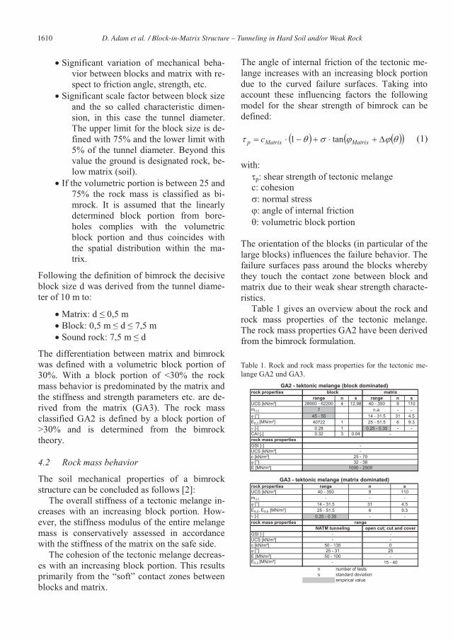
Inclinometer measurements detected the influ-ence of precipitation in particular after forest clearance by a significant increase of the creep-ing rate. Finally, in August 2008 the gravel piles were bored. During installation significant addi-tional slope movements were triggered and cracks were observed in a water supply tank si-tuated above the gravel piles (see Fig. 2). The re-sults of the near inclinometer B21 identified a sliding horizon in a depth of about 10 m below surface (see Fig. 3). By means of the morphology it was suggested that a set of local creep mass bodies with various sliding horizons exist.
Consequently, a comprehensive monitoring and data acquisition system was installed consist-ing of inclinometers, geodetic measurements and water quantity recordings (in the gravel piles).
From October 2008 additional slope deforma-tions occurred during the construction of the tun-nel sections No. 71 and No. 72 (see Fig. 2), the water supply tank was affected again. These slope movements resulted not only from the con-struction activities but originated from an in-creased wetting of the slope by intense precipita-tion and beginning of snow melting. After the installation of temporary anchorage of the retain-ing wall made of bored piles (see Fig. 3) the slope creep rate could be reduced again (surface deformation in Fig. 2).
Again in the period March to April 2009 short-term slope movements were observed dur-ing excavation works, which got under control after construction of the tunnel ceiling.
D. Adam et al. / Block-in-Matrix Structure – Tunneling in Hard Soil and/or Weak Rock 1611

Inclinometer B21 showed total surface deforma-tions of about 100 mm from the reference mea-surement in 2005 to April 2009. It had to be con-sidered that the natural creeping rate was included into the total deformations which weresuperimposed by the movements triggered by the construction activities. Taking into account the natural creeping rate additional deformations of about 55 mm occurred due to construction works (see Fig. 2).
Measurements of anchor forces showed that the maximum design working load was exceeded up to 25%, whereby no additional increase could be observed after the end of the construction works.
In the period April 2009 to May 2010 the mo-nitored movements were in the range of the natu-ral creeping rates. Gravel piles successfully drained the slope, the water flux was determined to an annual average of about 780 liters/day.
However, in May 2010 an increase of slope de-formations was observed again caused by the NATM tunneling in the creep mass. In advance
parametric studies were performed in order to investigate the influence of the creep behavior on the tunnel. The results of the analyses disclosed that the creep earth pressure (creep horizon close to the tunnel head) did not affect the bearing ca-pacity but the defined serviceability limit state of the tunnel lining was exceeded so that large de-formations and even cracks had to be expected. The attention had to be turned to the outer lining since the reinforced inner lining influenced the deformation only to a minor degree but served for a better distribution of the stresses and allow-able fissured cracks. These findings resulted in the decision to increase the thickness of the outer and the inner lining from 30 to 40 cm and to reinforce of the inner lining.
Moreover, a contingency plan was prepared to be able to carry out stabilization measures quick-ly if necessary. The stabilization measures in-cluded extensive slope dowelling by vertical and/or inclined piles.
According to Fig. 2 and Fig. 4 the deforma-tions in the tunnel roof amounted up to 8.5 cm and at the surface up to about 27 cm. The maxi-
Figure 2. Location of the tunnel within the creeping mass. The position of the gravel piles, the water supply tank and the incli-nometers are shown as well as the results of inclinometer measurements and of deformation measurements at the tunnel lining.
D. Adam et al. / Block-in-Matrix Structure – Tunneling in Hard Soil and/or Weak Rock1612
mum deformations of the tunnel lining were about 11 cm, whereby asymmetric deformation of the tunnel was observed as expected due to the lateral creeping behavior of the slope.
With respect to the total deformations of the tunnel lining the static calculations yielded that the ultimate bearing capacity of the shotcrete shell will not be reached and deformations at an early stage are not critical since the tunnel lining is relatively soft and the stresses are redistributed by creep. Only deformations occurring to a later state were detected to be problematic.
The tunnel excavation was executed in seg-ments (top heading, bench, and invert) with short-term ring closure. A pipe roof ensured pro-tection by means of pipes of a length up to 18 meters that were driven into the ground pre-parative and then secured by the use of shotcrete and, if applicable, supported by steel arches. Moreover self-bore anchors were installed (schematically in Fig. 4). All anchors oriented to
the creeping slope showed a loss of the applied pre-stress and anchor heads of anchors less than 10 m long displaced in direction of the cavity punching the girder. Thus, it could be assumed that the bond length of the anchors ended in the creep mass, which was confirmed by inclinome-ter measurements. Inclinometer B36 (see Fig. 4) indicated a significant sliding plane. However, the total deformations originated from deeper re-gions as well, which were obviously linked with the tunneling. Presumably, in a depth of about 20 m another sliding plane was generated.
Although the slope deformation rate decreased after completion of the tunnel again additional inclinometers were installed in the creeping slope and geodetic reading points at the tunnel lining as well. Thus, the monitoring of the slope and deformation measurement of the tunnel will be continued for at least 5 years after setting the tunnel in operation.
Figure 3. Tunnel cross section in the area of the cut-and-cover tunnel with an arched ceiling (section 71) with iden-tified sliding horizon.
D. Adam et al. / Block-in-Matrix Structure – Tunneling in Hard Soil and/or Weak Rock 1613
REFERENCES
[1] H. Brandl, J. Dalmatiner, Brunnenfundierungen von Bauwerken in Hängen (insbesondere Brücken), Bun-desministerium für wirtschaftliche Angelegenheiten, Straßenforschung, Heft 352; Wien 1988.
[2] E.S. Lindquist, The Strength and Deformation of Me-lange, Dissertation, University of California at Berke-ley; 1994.
[3] E. Button, G. Riedmüller, W. Schubert, K. Klima, E. Medley, Tunnelling in tectonic melanges – accomodat-ing the impacts of geomechanical complexities and ani-sotropic rock mass fabrics, Bulletin of Engineering Ge-ology and the Environment, 2003.
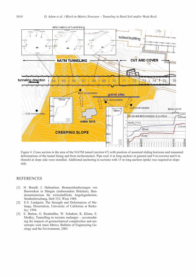
Figure 4. Cross section in the area of the NATM tunnel (section 67) with position of assumed sliding horizons and measured deformations of the tunnel lining and from inclinometers. Pipe roof, 6 m long anchors in general and 9 m (crown) and 6 m(bench) at slope side were installed. Additional anchoring in sections with 15 m long anchors (pink) was required at slope side.
D. Adam et al. / Block-in-Matrix Structure – Tunneling in Hard Soil and/or Weak Rock1614