Embed Size (px)
Citation preview
F i na l Spec i f i ca t i ons
Bldg 1784, Solar Renewable Energy System at Kalaeloa, Oahu, Hawaii
Contract Nos. PN#15120012, CA-1209-C
Prepared for
State of Hawaii Army National Guard
September 2014
1132 Bishop Street, Suite 1100Honolulu, Hawaii 96813
REQUIREMENTS AND SPECIFICATIONSTO FURNISH AND DELIVER MATERIALS FOR
BLDG 1784, SOLAR RENEWABLE ENERGY SYSTEM AT KALAELOA, HAWAII
CONTRACT NOS. PN#15120012, CA-1209-C
FOR THE DEPARTMENT OF DEFENSESTATE OF HAWAI’I HAWAII ARMY NATIONAL GUARD (HIARNG)
SEPTEMBER 2014
Consultant: CH2M HILL

Bldg. 1784, Solar Renewable Energy System Table of Contents Hawaii Army National Guard, Kalaeloa, HI 00 01 10 - 1 September 2014
TABLE OF CONTENTS
Page Number
TABLE OF CONTENTS Special Conditions ........................................................................................................... 1 –1
DIVISION 13 – SPECIAL CONSTRUCTION 13 34 19 Pre-Engineered Steel Support Structure .................................................. 1 –6
DIVISION 26 – ELECTRICAL
26 05 01 Electrical ................................................................................................... 1 –21 26 31 00 Grid-Tied Photovoltaic System ................................................................. 1 –11
DIVISION 31 – EARTHWORK 31 10 00 Site Clearing ............................................................................................. 1 –3 31 23 13 Subgrade Preparation .............................................................................. 1 –3 31 23 16 Excavation ................................................................................................ 1 –3 31 23 23.15 Trench Backfill .......................................................................................... 1 –9
DIVISION 32 – EXTERIOR IMPROVEMENTS 32 11 23 Aggregate Base Courses ......................................................................... 1 –5 32 12 16 Asphalt Concrete Pavement ..................................................................... 1 –8 32 91 13 Soil Preparation ........................................................................................ 1 –3 32 92 00 Lawns and Grasses .................................................................................. 1 –6
END OF SECTION

Bldg. 1784, Solar Renewable Energy System Special Conditions Hawaii Army National Guard, Kalaeloa, HI 1
SPECIAL CONDITIONS
1.01 GENERAL CONDITIONS
A. The General Conditions, these Special Conditions, and Additional General Conditions for Construction Contracts, shall govern all Work specified in all divisions and sections.
B. Revisions to General Conditions: The following conditions included in this paragraph and subparagraphs shall govern respective items in the General Conditions and in Additional General Conditions for Construction Contracts.
1. Project Manager: The Project Manager shall be notified of all submittals and construction matters sent to the Contracting Officer. Contractor shall also copy the Project Manager on all correspondence.

Bldg. 1784, Solar Renewable Energy System Pre-Engineered Steel Hawaii Army National Guard, Kalaeloa, HI Support Structure
13 34 19 - 1
SECTION 13 34 19 – PRE-ENGINEERED STEEL SUPPORT STRUCTURE
PART 1 - GENERAL
1.01 REFERENCES
A. The following is a list of standards that may be referenced in this section. The version of each document adopted by the 2009 International Building Code (IBC) shall be used:
1. American Institute of Steel Construction (AISC): a. 303, Code of Standard Practice for Steel Buildings and
Bridges.b. 360, Specification for Structural Steel Buildings. c. RCSC Specification for Structural Joints Using
ASTM A325 or A490 Bolts. d. Design Guide 3: Serviceability Design Considerations for
Steel Buildings. 2. American Iron and Steel Institute (AISI): Specification for the
Design of Cold-Formed Steel Structural Members. 3. American Society of Civil Engineers (ASCE): 7, Minimum
Design Loads for Buildings and Other Structures. 4. American Welding Society (AWS)
a. D1.1/D1.1M, Structural Welding Code – Steel. b. D1.3/D1.3M, Structural Welding Code – Sheet Steel.
5. ASTM International (ASTM): a. A36/A36M, Standard Specification for Carbon Structural
Steel.b. A307, Standard Specification for Carbon Steel Bolts and
Studs, 60,000 psi Tensile Strength. c. A325, Standard Specification for Structural Bolts, Steel,
Heat Treated, 120/105 ksi Minimum Tensile Strength. d. A490/A490M, Standard Specification for Structural Bolts,
Alloy Steel, Heat-Treated, 150 ksi Minimum Tensile Strength.
e. A529/A529M, Standard Specification for High-Strength Carbon-Manganese Steel of Structural Quality.
f. A572/A572M, Standard Specification for High-Strength Low-Alloy Columbium-Vanadium Structural Steel.
g. A653/A653M, Standard Specification for Steel Sheet, Zinc-Coated (Galvanized) or Zinc-Iron Alloy-Coated (Galvannealed) by the Hot-Dip Process.
h. A792/A792M, Standard Specification for Steel Sheet, 55% Aluminum-Zinc Alloy-Coated by the Hot-Dip Process.
i. A992/A992M, Standard Specification for Steel for Structural Shapes.
j. F1554, Standard Specification for Anchor Bolts, Steel, 36, 55, and 105-ksi Yield Strength.

Bldg. 1784, Solar Renewable Energy System Pre-Engineered Steel Hawaii Army National Guard, Kalaeloa, HI Support Structure
13 34 19 - 2
6. International Code Council (ICC): International Building Code (IBC).
7. Metal Building Manufacturer’s Association (MBMA): Metal Building Systems Manual.
1.02 SYSTEM DESCRIPTION
A. See design structural drawings for additional information.
B. The pre-engineered structure manufacturer shall provide all professional engineering services required to design the structure and submit design documents for review/approval.
C. Complete pre-engineered steel structure consisting of cantilever steel columns, primary steel framing including rigid moment resisting frame, and secondary framing for structural stability and support of MEP systems.
D. Provide all components necessary for a complete structure including, but not limited to, fasteners, anchors, flashing and trim materials, and coatings.
1.03 DESIGN REQUIREMENTS
A. Applicable Building Code: The 2009 International Building Code (IBC).
B. Applicable Design Standards:
1. ASCE 7. 2. AISC 360. 3. AISC Design Guide 3. 4. AISC RSCS. 5. AISI. 6. MBMA. 7. AWS D1.1, D1.3.
C. Design Loads: See structural design drawings for structural load criteria.
D. Deflection Criteria:
1. Lateral Drift: L/400. 2. Primary and Secondary Framing: L/240 total, L/360 due to live
or wind loads.
E. Consider secondary (P-Delta) load effects due to lateral drift of structure.
F. Column bases shall be designed with fixed moment resisting connections.
Bldg. 1784, Solar Renewable Energy System Pre-Engineered Steel Hawaii Army National Guard, Kalaeloa, HI Support Structure
13 34 19 - 3
1.04 CONTRACTOR/METAL BUILDING MANUFACTURER COORDINATION
A. Contractor shall submit column base reactions, determined by the pre-engineered structure Engineer, for confirmation that the reactions are within the limits used for the foundation design. This shall be completed prior to start of foundation work, or fabrication of the pre-engineered structure.
B. Contractor shall verify interface of building components with foundation and immediately notify the Contracting Officer of any conflicts.
1.05 SUBMITTALS
A. Manufacturer’s literature and technical data.
B. Drawings Stamped by a Professional Engineer:
1. Drawings shall be specifically prepared for this Project. 2. Show design load criteria, material specifications for framing
members and connections, roof framing plan with dimensions and member sizes, baseplate details showing anchor bolt size and bolt layout, instructions for temporary bracing, and sections and details for all components and accessories.
3. Identify QC/QA tests, inspections, and activities required for code compliance of the pre-engineered structure.
4. Painting System: Specifications; include paint manufacturer’s name, product trade name, and preparation for shop and field coats.
C. Samples: Provide samples for paint manufacturer’s available color options conforming to the Installation Design Guide. Samples shall be a minimum 2-inch by 3-inch metal sample for components requiring color and finish selection.
D. Structural Calculations Stamped by a Professional Engineer:
1. Complete analysis and design of structural components and connections in accordance with design requirements indicated.
2. Summary of column reactions to foundation.
E. Manufacturer’s written instructions for shipping, handling, storage, protection, and erection or installation of building and components.
F. Qualifications:
1. Manufacturer: Erector.
Bldg. 1784, Solar Renewable Energy System Pre-Engineered Steel Hawaii Army National Guard, Kalaeloa, HI Support Structure
13 34 19 - 4
1.06 QUALITY ASSURANCE
A. Qualifications:
1. Designer: Registered professional engineer. 2. Manufacturer: 5 years of documented experience with similar
projects. Subject to approval of the Contracting Officer. 3. Erector:
a. 5 years of documented experience with similar projects. Subject to approval of the Contracting Officer.
b. Approval by manufacturer.
1.07 DELIVERY, STORAGE, AND HANDLING
A. Protect building components and accessories from corrosion, deformation, and other damage during delivery, storage, and handling.
B. Deliver to Site with parts individually tagged.
C. Store on wood blocking or pallets, flat and off ground, to keep clean and to prevent damage or permanent distortion. Support bundles so there is no danger of tipping, sliding, rolling, shifting, or material damage. Cover with tarpaulins or other suitable weather tight ventilated covering.
D. Protect finish of metal panels by application of removable plastic film or other suitable material placed between panels. Do not allow panels to come in contact with other material that would result in scratching, denting, staining or other damage to panel finish.
1.08 SPECIAL GUARANTEE
A. Furnish manufacturer’s extended guarantee or warranty, with Owner named as beneficiary, in writing, as special guarantee. Special guarantee shall provide for correction, or at the option of Owner, removal and replacement of Work specified in this specification, excluding coatings, found defective during a minimum period of 20 years after date of Substantial Completion. Duties and obligations for correction or removal and replacement of defective work as specified in the General Conditions.
B. Conditions: Finishes will not chalk, crack, check, blister, peel, flake, chip, or lose adhesion for 5 years.

Bldg. 1784, Solar Renewable Energy System Pre-Engineered Steel Hawaii Army National Guard, Kalaeloa, HI Support Structure
13 34 19 - 5
PART 2 PRODUCTS
2.01 COMPONENTS
A. Structural Framing and Bracing:
1. Steel Framing: ASTM A36/A36M, ASTM A529/A529M, ASTM A572/A572M, or ASTM A992 with 3/16-inch minimum thickness. G90 galvanized coating and factory primer with finish coating.
2. Cold Formed Steel Framing: Steel for cold-formed galvanized channel and z-sections shall be ASTM A653/A653M, Structural Steel (SS) Grade 33 or High-Strength Low-Alloy Steel (HSLAS) Grade 50 Type A or B, with minimum design thickness equal to 0.0346 inch. G90 galvanized coating and factory primer with finish coating.
3. Bolted Connections: ASTM A307, A325, A490, G90 galvanized bolts and hardware.
4. Weld Filler Metal: AWS D1.1 or AWS D1.3.
2.02 ACCESSORIES
A. Provide all components necessary for a complete structure including, but not limited to, fasteners, anchors, flashing and trim materials, and coatings.
2.03 FABRICATION
A. Factory Fabricate: To manufacturer’s written standards, MBMA Metal Building Systems Manual, and AISC Specifications for Structural Steel Buildings.
B. Building Parts: Accurate and true to dimension to facilitate building erection without cutting, fitting, or other alterations.
C. Welded Connections: In accordance with AWS D1.1 or D1.3.
D. Finish Coatings: After galvanizing, apply manufacturer’s standard primer and two coats of manufacturer’s standard finish paint in accordance with MBMA Metal Building Systems Manual. Color shall be selected by the Owner from the manufacturer’s available standard colors.
PART 3 EXECUTION
3.01 EXAMINATION
A. Examine supporting concrete foundation and anchor bolt placement for compliance with requirements for installation tolerances and other conditions affecting performance of metal building.

Bldg. 1784, Solar Renewable Energy System Pre-Engineered Steel Hawaii Army National Guard, Kalaeloa, HI Support Structure
13 34 19 - 6
3.02 BUILDING ERECTION
A. Erect building system in accordance with manufacturer’s standards, AISC 303, and applicable health and safety regulations.
B. Provide temporary bracing in accordance with MBMA standards and as required for safe installation.
C. Structural Framing:
1. Do not field cut or alter primary or secondary framing members. 2. Installation and tolerances shall be in accordance with MBMA
Metal Building Systems Manual.
3.03 REPAIR, CLEANING, AND PAINTING
A. Immediately following erection, remove unused material, screws, fasteners, and other debris from completed installation. Use caution in removing metal cuttings from surface of prefinished metal.
B. Replace damaged, dented, buckled, or discolored components.
C. Repair damaged painted and galvanized surfaces in accordance with building manufacturer’s instruction.
3.04 FIELD QUALITY CONTROL
A. The Contractor shall perform and document all quality control tests and inspections required by the pre-engineered structure Engineer.
3.05 FIELD QUALITY ASSURANCE
A. The Contractor shall engage 3rd party test and inspection agencies to perform the Special Tests and Inspections identified in Design Drawing G-3.
3.06 MANUFACTURER’S SERVICES
A. Provide manufacturer’s representative at Site for inspection, and certification of proper installation.
END OF SECTION
Bldg. 1784, Solar Renewable Energy System Electrical Hawaii Army National Guard, Kalaeloa, HI 26 05 01 - 1
SECTION 26 05 01 - ELECTRICAL
PART 1 GENERAL
1.01 APPLICABILITY
A. Except as otherwise indicated, electrical work shall be provided and installed as described herein.
1.02 REFERENCES
A. The following is a list of standards that may be referenced in this section:
1. American National Standards Institute (ANSI): ANSI/SCTE 77, Specification for Underground Enclosure Integrity.
2. ASTM International (ASTM): a. A167, Standard Specification for Stainless and Heat-
Resisting Chromium-Nickel Steel Plate, Sheet, and Strip. b. A240/A240M, Standard Specification for Heat-Resisting
Chromium and Chromium-Nickel Stainless Steel Plate, Sheet, and Strip for Pressure Vessels.
c. A1011/A1011M, Standard Specification for Steel, Sheet and Strip, Hot-Rolled, Carbon, Structural, High-Strength Low-Alloy and High-Strength Low-Alloy with Improved Formability.
d. B8, Standard Specification for Concentric-Lay-Stranded Copper Conductors, Hard, Medium-Hard, or Soft.
e. C857, Standard Practice for Minimum Structural Design Loading for Underground Precast Concrete Utility Structures.
3. Federal Specifications (FS): W-C-596, Connector, Electrical, Power, General Specification for.
4. Institute of Electrical and Electronics Engineers (IEEE): a. C62.41, Recommended Practice on Surge Voltages in
Low-Voltage AC Power Circuits. b. PC62.41.1, Draft Guide on the Surge Environment in Low-
Voltage (1000 V and less) AC Power Circuits. 5. International Electrical Testing Association (NETA): ATS,
Acceptance Testing Specifications for Electrical Power Distribution Equipment and Systems.
6. National Electrical Contractor’s Association, Inc. (NECA): 1, Standard Practices for Good Workmanship in Electrical Contracting.
7. National Electrical Manufacturers Association (NEMA): a. C80.1, Rigid Steel Conduit-Zinc Coated. b. C80.3, Electrical Metallic Tubing-Zinc Coated. c. 250, Enclosures for Electrical Equipment (1,000 Volts
Maximum). d. ICS 1, Industrial Control and Systems: General
Requirements.

Bldg. 1784, Solar Renewable Energy System Electrical Hawaii Army National Guard, Kalaeloa, HI 26 05 01 - 2
e. KS 1, Enclosed and Miscellaneous Distribution Equipment.
f. PB 1, Panelboards. g. ST 20, Dry Type Transformers for General Applications. h. TC 2, Electrical Polyvinyl Chloride (PVC) Tubing and
Conduit.i. TC 3, PVC Fittings for Use with Rigid PVC Conduit and
Tubing.j. WC 70, Standard for Non-Shielded Power Cables Rated
2000 V or Less for the Distribution of Electrical Energy. k. WD 1, General Color Requirements for Wiring Devices.
8. National Fire Protection Association (NFPA): 70, National Electrical Code (NEC).
9. Underwriters Laboratories, Inc. (UL): a. 1, Flexible Metal Conduit. b. 6, Electrical Rigid Metal Conduit—Steel. c. 44, Thermoset Insulated Wires and Cables. d. 62, Flexible Cord and Fixture Wire. e. 67, Panelboards. f. 98, Enclosed and Dead-Front Switches. g. 360, Liquid-Tight Flexible Steel Conduit. h. 486A, Wire Connectors and Soldering Lugs for Use with
Copper Conductors. i. 486C, Splicing Wire Connectors. j. 489, Molded-Case Circuit Breakers, Molded-Case
Switches, and Circuit Breaker Enclosures. k. 508, Industrial Control Equipment. l. 510, Polyvinyl Chloride, Polyethylene and Rubber
Insulating Tape. m. 514B, Fittings for Cable and Conduit. n. 651, Schedule 40 and 80 PVC Conduit. o. 797, Electrical Metallic Tubing. p. 870, Wireways, Auxiliary Gutters, and Associated Fittings. q. 943, Ground-Fault Circuit Interrupters. r. 1059, Terminal Blocks. s. 1449, Transient Voltage Surge Suppressors. t. 1479, Fire Stop System Standard. u. 2231, Personnel Protection Systems for EV Charging
Circuits.v. 2594, EV Supply Equipment.
1.03 SUBMITTALS
A. Action Submittals:
1. Metering equipment. 2. Boxes and device plates. 3. Junction and pull boxes. 4. Handholes. 5. Wiring devices. 6. Panelboards.

Bldg. 1784, Solar Renewable Energy System Electrical Hawaii Army National Guard, Kalaeloa, HI 26 05 01 - 3
7. Electric Vehicle Charging Station. 8. Circuit breakers and switches. 9. Control devices, terminal blocks, and relays. 10. Support and framing channels. 11. Nameplates and nameplate schedule. 12. TVSS equipment. 13. Conduit, fittings, and accessories. 14. Conductors, cable, and accessories. 15. Grounding materials.
B. Informational Submittals:
1. Factory test reports. 2. Field test reports. 3. Signed permits indicating Work is acceptable to regulatory
authorities having jurisdiction. 4. Operation and Maintenance Data:
a. Provide for all equipment, as well as each device having features that can require adjustment, configuration, or maintenance.
b. Minimum information shall include manufacturer’s preprinted instruction manual, one copy of the approved submittal information for the item, tabulation of any settings, and copies of any test reports.
1.04 AUTHORITY HAVING JURISDICTION (AHJ)
A. Provide the Work in accordance with NFPA 70, National Electrical Code (NEC). Where required by the AHJ, material and equipment shall be labeled or listed by a nationally recognized testing laboratory or other organization acceptable to the AHJ in order to provide a basis for approval under NEC.
B. Materials and equipment manufactured within the scope of standards published by Underwriters Laboratories, Inc. shall conform to those standards and shall have an applied UL listing mark.
PART 2 PRODUCTS
2.01 GENERAL
A. Where two or more units of the same class of material or equipment are required, provide products of a single manufacturer. Component parts of materials or equipment need not be products of the same manufacturer.
B. Material and equipment shall be suitable for continuous operation in the environmental conditions in which they are installed.
Bldg. 1784, Solar Renewable Energy System Electrical Hawaii Army National Guard, Kalaeloa, HI 26 05 01 - 4
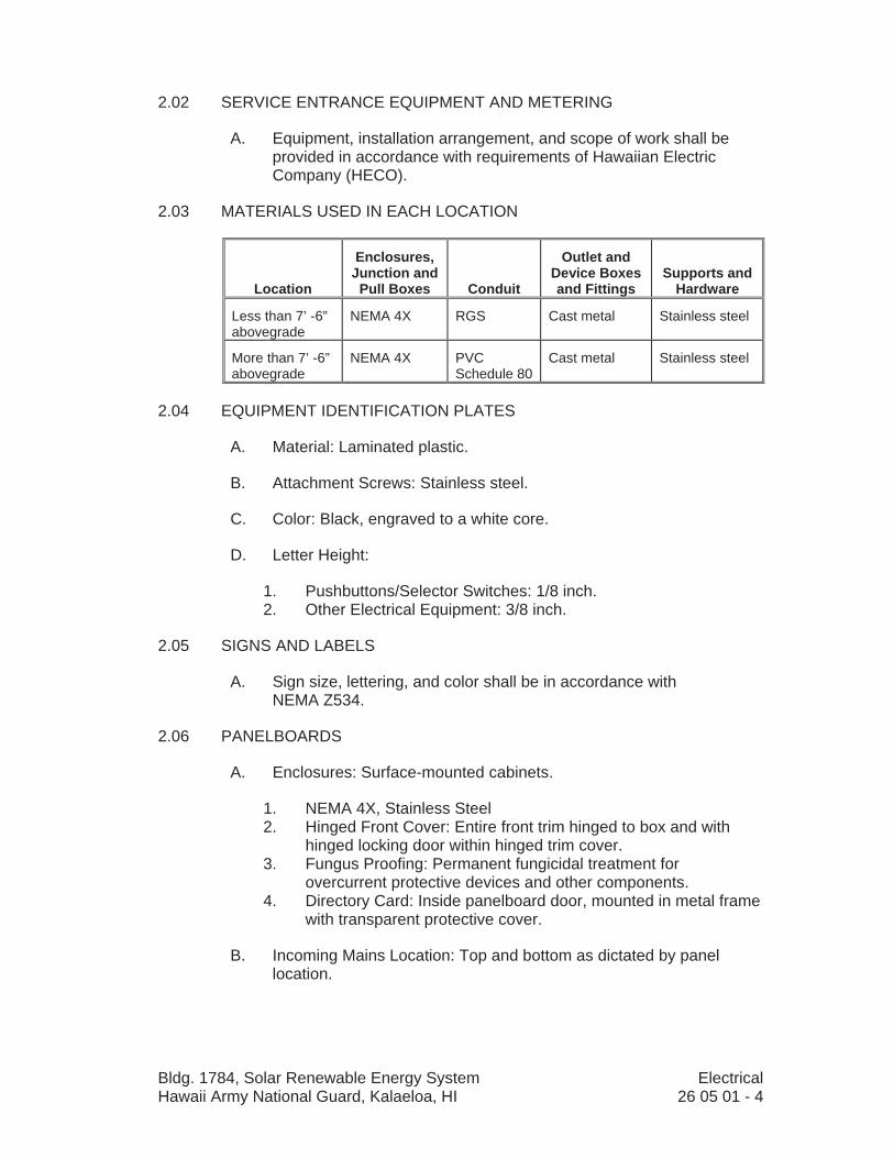
2.02 SERVICE ENTRANCE EQUIPMENT AND METERING
A. Equipment, installation arrangement, and scope of work shall be provided in accordance with requirements of Hawaiian Electric Company (HECO).
2.03 MATERIALS USED IN EACH LOCATION
Location
Enclosures,Junction and
Pull Boxes Conduit
Outlet and Device Boxes and Fittings
Supports and Hardware
Less than 7’ -6” abovegrade
NEMA 4X RGS Cast metal Stainless steel
More than 7’ -6” abovegrade
NEMA 4X PVC Schedule 80
Cast metal Stainless steel
2.04 EQUIPMENT IDENTIFICATION PLATES
A. Material: Laminated plastic.
B. Attachment Screws: Stainless steel.
C. Color: Black, engraved to a white core.
D. Letter Height:
1. Pushbuttons/Selector Switches: 1/8 inch. 2. Other Electrical Equipment: 3/8 inch.
2.05 SIGNS AND LABELS
A. Sign size, lettering, and color shall be in accordance with NEMA Z534.
2.06 PANELBOARDS
A. Enclosures: Surface-mounted cabinets.
1. NEMA 4X, Stainless Steel 2. Hinged Front Cover: Entire front trim hinged to box and with
hinged locking door within hinged trim cover. 3. Fungus Proofing: Permanent fungicidal treatment for
overcurrent protective devices and other components. 4. Directory Card: Inside panelboard door, mounted in metal frame
with transparent protective cover.
B. Incoming Mains Location: Top and bottom as dictated by panel location.
Bldg. 1784, Solar Renewable Energy System Electrical Hawaii Army National Guard, Kalaeloa, HI 26 05 01 - 5
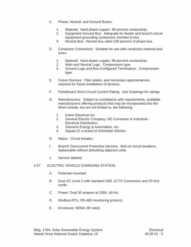
C. Phase, Neutral, and Ground Buses:
1. Material: Hard-drawn copper, 98 percent conductivity. 2. Equipment Ground Bus: Adequate for feeder and branch-circuit
equipment grounding conductors; bonded to box. 3. Neutral Bus: Neutral bus rated 100 percent of phase bus.
D. Conductor Connectors: Suitable for use with conductor material and sizes.
1. Material: Hard-drawn copper, 98 percent conductivity. 2. Main and Neutral Lugs: Compression type. 3. Ground Lugs and Bus-Configured Terminators: Compression
type.
E. Future Devices: Filler plates, and necessary appurtenances required for future installation of devices.
F. Panelboard Short-Circuit Current Rating: See Drawings for ratings.
G. Manufacturers: Subject to compliance with requirements, available manufacturers offering products that may be incorporated into the Work include, but are not limited to, the following:
1. Eaton Electrical Inc. 2. General Electric Company; GE Consumer & Industrial -
Electrical Distribution. 3. Siemens Energy & Automation, Inc. 4. Square D; a brand of Schneider Electric.
H. Mains: Circuit breaker.
I. Branch Overcurrent Protective Devices: Bolt-on circuit breakers, replaceable without disturbing adjacent units.
J. Service labeled.
2.07 ELECTRIC VEHICLE CHARGING STATION
A. Pedestal mounted.
B. Dual AC Level 2 with standard SAE J1772 Connectors and 20 foot cords.
C. Power: Dual 30 ampere at 208V, 60 Hz.
D. Modbus RTU, RS-485 monitoring protocol.
E. Enclosure: NEMA 3R rated.

Bldg. 1784, Solar Renewable Energy System Electrical Hawaii Army National Guard, Kalaeloa, HI 26 05 01 - 6
F. Manufacturer and Products:
1. Basis of Design: Eaton; No. SDR3BX00. 2. Or Approved Equal.
2.08 HANDHOLES
A. Construction: Precast polymer concrete, up to 30 by 48 inches.
B. Listing: UL for both enclosure and cover.
C. Loading: ANSI/SCTE 77, Tier 15 for applications subject to occasional non-deliverable heavy vehicular traffic.
D. Drainage: Open bottom.
E. Raceway Entrances: Mouse holes (stacked), knockouts, or core drilled infield as required.
F. Covers: Bolt-on (stainless steel bolts) with “ELECTRIC” logo.
G. Size: As required, 16 by 24 inches minimum clear inside.
H. Manufacturer and Models: Hubbell Quazite PG, PT, and PC style enclosures with heavy duty (HA) covers.
2.09 THERMAL MAGNETIC MOLDED CASE CIRCUIT BREAKER
A. General: Molded case with trip ratings between 15 and 800 amps, 600V ac or less, suitable for mounting and operating in any position, and conforming to NEMA AB 1 and UL 489.
B. Operating Mechanism: Trip-free, toggle type handle with quick-make, quick-break action. Provide locking provisions for padlocking breaker in open position. Provide ON/OFF and TRIPPED indicating positions of operating handle. Operating handle is to assume a center position when tripped.
C. Trip Mechanism: Individual permanent thermal and magnetic trip elements in each pole with variable magnetic trip elements with a single continuous adjustment 3X to 10X for frames greater than 100 amps. Two- and three-pole, are to be common trip which automatically opens all poles when overcurrent occurs on one pole. Provide test button on cover. Trips to be calibrated for 40 degrees C ambient unless otherwise indicated.
D. Short Circuit Interrupting Ratings: 10 kA up to 250V and 14 kA over 250V, except greater where indicated on the Drawings.
E. Series Connected Ratings: Prohibited.
Bldg. 1784, Solar Renewable Energy System Electrical Hawaii Army National Guard, Kalaeloa, HI 26 05 01 - 7
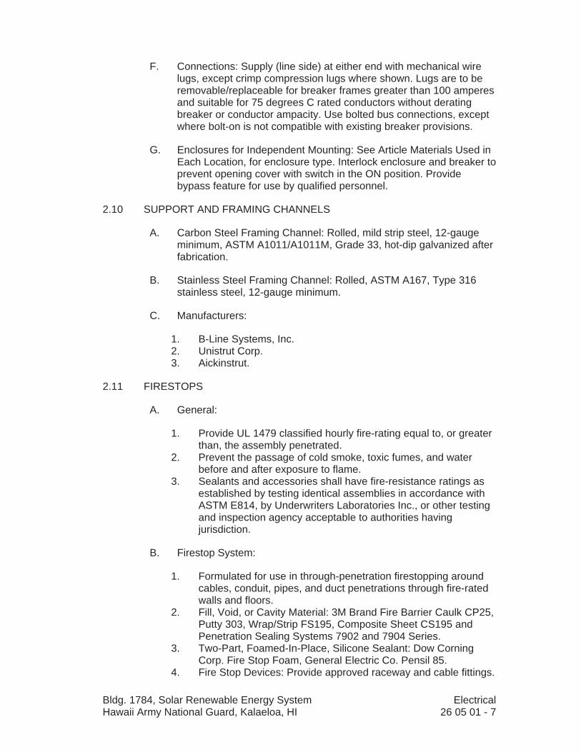
F. Connections: Supply (line side) at either end with mechanical wire lugs, except crimp compression lugs where shown. Lugs are to be removable/ replaceable for breaker frames greater than 100 amperes and suitable for 75 degrees C rated conductors without derating breaker or conductor ampacity. Use bolted bus connections, except where bolt-on is not compatible with existing breaker provisions.
G. Enclosures for Independent Mounting: See Article Materials Used in Each Location, for enclosure type. Interlock enclosure and breaker to prevent opening cover with switch in the ON position. Provide bypass feature for use by qualified personnel.
2.10 SUPPORT AND FRAMING CHANNELS
A. Carbon Steel Framing Channel: Rolled, mild strip steel, 12-gauge minimum, ASTM A1011/A1011M, Grade 33, hot-dip galvanized after fabrication.
B. Stainless Steel Framing Channel: Rolled, ASTM A167, Type 316 stainless steel, 12-gauge minimum.
C. Manufacturers:
1. B-Line Systems, Inc. 2. Unistrut Corp. 3. Aickinstrut.
2.11 FIRESTOPS
A. General:
1. Provide UL 1479 classified hourly fire-rating equal to, or greater than, the assembly penetrated.
2. Prevent the passage of cold smoke, toxic fumes, and water before and after exposure to flame.
3. Sealants and accessories shall have fire-resistance ratings as established by testing identical assemblies in accordance with ASTM E814, by Underwriters Laboratories Inc., or other testing and inspection agency acceptable to authorities having jurisdiction.
B. Firestop System:
1. Formulated for use in through-penetration firestopping around cables, conduit, pipes, and duct penetrations through fire-rated walls and floors.
2. Fill, Void, or Cavity Material: 3M Brand Fire Barrier Caulk CP25, Putty 303, Wrap/Strip FS195, Composite Sheet CS195 and Penetration Sealing Systems 7902 and 7904 Series.
3. Two-Part, Foamed-In-Place, Silicone Sealant: Dow Corning Corp. Fire Stop Foam, General Electric Co. Pensil 85.
4. Fire Stop Devices: Provide approved raceway and cable fittings.
Bldg. 1784, Solar Renewable Energy System Electrical Hawaii Army National Guard, Kalaeloa, HI 26 05 01 - 8
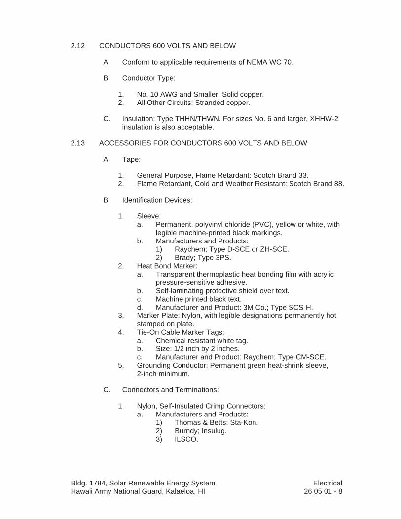
2.12 CONDUCTORS 600 VOLTS AND BELOW
A. Conform to applicable requirements of NEMA WC 70.
B. Conductor Type:
1. No. 10 AWG and Smaller: Solid copper. 2. All Other Circuits: Stranded copper.
C. Insulation: Type THHN/THWN. For sizes No. 6 and larger, XHHW-2 insulation is also acceptable.
2.13 ACCESSORIES FOR CONDUCTORS 600 VOLTS AND BELOW
A. Tape:
1. General Purpose, Flame Retardant: Scotch Brand 33. 2. Flame Retardant, Cold and Weather Resistant: Scotch Brand 88.
B. Identification Devices:
1. Sleeve: a. Permanent, polyvinyl chloride (PVC), yellow or white, with
legible machine-printed black markings. b. Manufacturers and Products:
1) Raychem; Type D-SCE or ZH-SCE. 2) Brady; Type 3PS.
2. Heat Bond Marker: a. Transparent thermoplastic heat bonding film with acrylic
pressure-sensitive adhesive. b. Self-laminating protective shield over text. c. Machine printed black text. d. Manufacturer and Product: 3M Co.; Type SCS-H.
3. Marker Plate: Nylon, with legible designations permanently hot stamped on plate.
4. Tie-On Cable Marker Tags: a. Chemical resistant white tag. b. Size: 1/2 inch by 2 inches. c. Manufacturer and Product: Raychem; Type CM-SCE.
5. Grounding Conductor: Permanent green heat-shrink sleeve, 2-inch minimum.
C. Connectors and Terminations:
1. Nylon, Self-Insulated Crimp Connectors: a. Manufacturers and Products:
1) Thomas & Betts; Sta-Kon. 2) Burndy; Insulug. 3) ILSCO.

Bldg. 1784, Solar Renewable Energy System Electrical Hawaii Army National Guard, Kalaeloa, HI 26 05 01 - 9
2. Nylon, Self-Insulated, Crimp Locking-Fork, Torque-Type Terminator:a. Suitable for use with 75 degrees C wire at full NFPA 70,
75 degrees C ampacity. b. Seamless. c. Manufacturers and Products:
1) Thomas & Betts; Sta-Kon. 2) Burndy; Insulink. 3) ILSCO; ILSCONS.
3. Self-Insulated, Freespring Wire Connector (Wire Nuts): a. UL 486. b. Plated steel, square wire springs. c. Manufacturers and Products:
1) Thomas & Betts. 2) Ideal; Twister.
4. Self-Insulated, Set Screw Wire Connector: a. Two piece compression type with set screw in brass
barrel.b. Insulated by insulator cap screwed over brass barrel. c. Manufacturers:
1) 3M Co. 2) Thomas & Betts. 3) Marrette.
D. Cable Lugs:
1. In accordance with NEMA CC 1. 2. Rated 600 volts of same material as conductor metal. 3. Uninsulated, Crimp Connectors and Terminators:
a. Suitable for use with 75 degrees C wire at full NFPA 70, 75 degrees C ampacity.
b. Manufacturers and Products: 1) Thomas & Betts; Color-Keyed. 2) Burndy; Hydent. 3) ILSCO.
4. Uninsulated, Bolted, Two-Way Connectors and Terminators: a. Manufacturers and Products:
1) Thomas & Betts; Locktite. 2) Burndy; Quiklug. 3) ILSCO.
E. Cable Ties:
1. Nylon, adjustable, self-locking, and reusable. 2. Manufacturer and Product: Thomas & Betts; TY-RAP.
F. Heat Shrinkable Insulation:
1. Thermally stabilized cross-linked polyolefin. 2. Manufacturer and Product: Thomas & Betts; SHRINK-KON.
Bldg. 1784, Solar Renewable Energy System Electrical Hawaii Army National Guard, Kalaeloa, HI 26 05 01 - 10
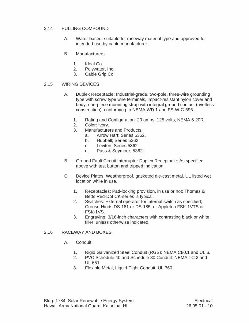
2.14 PULLING COMPOUND
A. Water-based, suitable for raceway material type and approved for intended use by cable manufacturer.
B. Manufacturers:
1. Ideal Co. 2. Polywater, Inc. 3. Cable Grip Co.
2.15 WIRING DEVICES
A. Duplex Receptacle: Industrial-grade, two-pole, three-wire grounding type with screw type wire terminals, impact-resistant nylon cover and body, one-piece mounting strap with integral ground contact (rivetless construction), conforming to NEMA WD 1 and FS-W-C-596.
1. Rating and Configuration: 20 amps, 125 volts, NEMA 5-20R. 2. Color: Ivory. 3. Manufacturers and Products:
a. Arrow Hart; Series 5362. b. Hubbell; Series 5362. c. Leviton; Series 5362. d. Pass & Seymour; 5362.
B. Ground Fault Circuit Interrupter Duplex Receptacle: As specified above with test button and tripped indication.
C. Device Plates: Weatherproof, gasketed die-cast metal, UL listed wet location while in use.
1. Receptacles: Pad-locking provision, in use or not; Thomas & Betts Red-Dot CK-series is typical.
2. Switches: External operator for internal switch as specified; Crouse-Hinds DS-181 or DS-185, or Appleton FSK-1VTS or FSK-1VS.
3. Engraving: 3/16-inch characters with contrasting black or white filler, unless otherwise indicated.
2.16 RACEWAY AND BOXES
A. Conduit:
1. Rigid Galvanized Steel Conduit (RGS): NEMA C80.1 and UL 6. 2. PVC Schedule 40 and Schedule 80 Conduit: NEMA TC 2 and
UL 651. 3. Flexible Metal, Liquid-Tight Conduit: UL 360.

Bldg. 1784, Solar Renewable Energy System Electrical Hawaii Army National Guard, Kalaeloa, HI 26 05 01 - 11
B. Conduit Fittings:
1. Rigid Galvanized Steel and Intermediate Metal Conduit: UL 514B, threaded.
2. Flexible Metal, Liquid-Tight Conduit: Metal insulated throat connectors with integral nylon or plastic bushing and sealing O-rings.
C. Outlet and Device Boxes:
1. Cast Metal: Box and cover of malleable iron or ferrous metal; gasketed weatherproof with stainless steel screws; threaded hubs.
2. Nonmetallic: Box and Cover of PVC, gasketed weatherproof with stainless steel screws.
D. Junction and Pull Boxes:
1. Outlet Box Used as Junction or Pull Box: As specified above. 2. Large Box: NEMA 250, Type 4X; stainless steel box with full
access, screw type cover and stainless steel screws.
E. Conduit Accessories:
1. Warning Tape: Polyethylene, 4-mil gauge with detectable strip, standard APWA/ANSI Z53.1 color for circuit type, 6 inches wide with permanent black lettering imprinted continuously over entire length; similar to Panduit Type HTDU and Reef Industries Terra Tape.
2. Heat Shrinkable Tubing: Cross-linked polyolefin, semi-flexible with meltable adhesive inner liner, as manufactured by Raychem.
3. Wraparound Duct Band: Heat-shrinkable, cross-linked polyolefin, precoated with hot-melt adhesive, of 50-mm width (minimum); similar to Raychem Type TWD.
2.17 TERMINAL BLOCKS
A. Type: UL 1059. Compression screw clamp, with current bar providing direct contact with wire and yoke, with individual rail mounted terminals. Marking system shall permit use of preprinted or field-marked tags.
B. Yokes and Clamping Screws: Zinc-plated, hardened steel.
C. Rating: 600V ac.
D. Manufacturers:
1. Weidmuller, Inc. 2. Ideal.
Bldg. 1784, Solar Renewable Energy System Electrical Hawaii Army National Guard, Kalaeloa, HI 26 05 01 - 12
2.18 GROUNDING
A. Ground Rods: Provide copper-clad steel with minimum diameter of 3/4-inch, and length of 10 feet.
B. Ground Conductors: As specified in Article Conductors and Cable.
C. Connectors.
1. Exothermic Weld Type: a. Outdoor Weld: Suitable for exposure to elements or direct
burial.b. Manufacturers:
1) Erico Products, In; Cadweld and Cadweld Exolon. 2) Thermoweld.
2. Compression Type: a. Compress-deforming type; wrought copper extrusion
material.b. Single indentation for conductors 6 AWG and smaller. c. Double indentation with extended barrel for conductors
4 AWG and larger. d. Single barrels prefilled with oxide-inhibiting and antiseizing
compound.e. Manufacturers:
1) Burndy Corp. 2) Thomas & Betts. 3) ILSCO.
PART 3 EXECUTION
3.01 GENERAL
A. Electrical Drawings show general locations of equipment, devices, and raceway, unless specifically dimensioned. Electrical installers shall be responsible for actual location of equipment and devices and for proper routing and support of raceways, subject to approval of Contracting Officer.
B. Check approximate locations of outlets, equipment, and other electrical system components indicated for conflicts with openings, structural members, and components of other systems and equipment having fixed locations. In the event of conflicts, notify Contracting Officer.
C. Install work in accordance with NECA Standards of Installation, unless otherwise specified.
D. Keep openings in boxes and equipment closed during construction.
E. Lay out work carefully in advance. Do not cut or notch any structural member or building surface without specific approval of Contracting Officer. Carefully perform cutting, channeling, chasing, or drilling of

Bldg. 1784, Solar Renewable Energy System Electrical Hawaii Army National Guard, Kalaeloa, HI 26 05 01 - 13
floors, walls, partitions, ceilings, paving, or other surfaces required for the installation, support, or anchorage of conduit, raceways, or other electrical materials and equipment. Following such work, restore surfaces to original condition.
3.02 EXISTING CONDITIONS
A. Where new work interferes with existing circuits and equipment which is not to be removed, such circuits and equipment shall be reworked and relocated as required to complete the Project.
B. Existing equipment and circuiting shown are based upon limited field surveys and Government furnished Drawings. The Contractor shall verify conditions as they exist, make all necessary adjustments, and record the work on the Record Drawings.
3.03 CONTINUITY OF SERVICE
A. Interruption of power to loads, and communications circuits, within or serving operational areas is prohibited. Provide temporary wiring, distribution equipment, and so forth, as required to maintain continuity of service to operational areas throughout the construction period.
B. Continuous uninterrupted service to operational areas and equipment serving operational areas is required; however, special circumstances may arise where the Government’s interest may best be served by a temporary interruption of service to operational areas and/or equipment. The Contractor may propose such outages in writing to the Contracting Officer.
C. Electrical outages must be held to a minimum. The Contractor shall submit a Method of Procedure (MOP) for each outage to the Contracting Officer, detailing the reasons for the outage, areas affected, sequence of procedures to accomplish work, estimated maximum duration, the date and time of day outage will occur. The Contractor shall meet with the Contracting Officer to set a schedule and date for the outage based upon the MOP. The Contracting Officer may direct the Contractor as to the time of day or night and date an outage may take place.
3.04 EQUIPMENT INSTALLATION
A. General:
1. Install equipment in accordance with NEMA ICS 2.3, ANSI C2, approved submittals, and manufacturer’s written installation instructions and recommendations.
2. Install panelboards and accessories according to NEMA PB 1.1 and NECA 1.
3. Mount top of trim 90 inches above finished floor unless otherwise indicated.
Bldg. 1784, Solar Renewable Energy System Electrical Hawaii Army National Guard, Kalaeloa, HI 26 05 01 - 14
4. Mount panelboard cabinet plumb and rigid without distortion of box.
5. Install filler plates in unused spaces. 6. Use a computer or typewriter to create panel directory;
handwritten directories are not acceptable. 7. Install the anchor bolts to secure equipment to substrate to meet
specified seismic requirements. 8. Install equipment plumb and in longitudinal alignment with pad
or wall. 9. Coordinate terminal connections and provide specified
conductor lugs as required to complete connection of the equipment.
10. Using calibrated torque wrench or driver (re)tighten current-carrying bolted connections and enclosure support framing and panels to manufacturer’s torque recommendations.
11. Adjust equipment door and panels for proper alignment and free-swinging door operation and latching.
12. Record changes to equipment supplier approved drawings to reflect as-built conditions.
3.05 IDENTIFICATION PLATES, SIGNS, AND LABELS
A. Multiple Power Supply Sign: Provide permanent identification plate at equipment served by more than one feeder or branch circuit.
B. Equipment Identification: Provide a plate to label new electrical equipment including switchboard breakers, transformers, terminal junction boxes, and disconnect switches. Include name and number of equipment powered or controlled.
3.06 HANDHOLES
A. Set on minimum 6-inch thick 3/4-inch minus gravel base extending 12 inches beyond box base on all sides.
B. Provide 10-inch wide by 12-inch deep poured-in-place concrete collar around box in accordance with manufacturer’s details; such as Quazite Concrete Collar Applications bulletin.
C. Install such that raceways enter at nearly right angles.
3.07 SUPPORT AND FRAMING CHANNEL
A. Install where required for mounting and supporting electrical equipment, raceway, and cable tray systems.
B. Channel Type: Specified in Article Materials Used in Each Location.
C. Paint cut ends of carbon steel channel with zinc-rich primer prior to installation, unless hot dipped galvanized after cut.

Bldg. 1784, Solar Renewable Energy System Electrical Hawaii Army National Guard, Kalaeloa, HI 26 05 01 - 15
3.08 FIRESTOPS
A. Install in strict conformance with manufacturer’s instructions. Comply with installation requirements established by testing and inspecting agency.
B. Sealant: Install sealant, including forming, packing, and other accessory materials, to fill openings around electrical conduits penetrating floors and walls, to provide firestops with fire-resistance ratings indicated for floor or wall assembly in which penetration occurs.
3.09 CONDUCTORS
A. General:
1. Conductor installation shall be in accordance with manufacturer’s recommendations, including maximum pulling tensions and minimum bending radii.
2. Tighten screws and terminal bolts in accordance with UL 486A-486B for copper conductors.
3. Cable Lugs: Provide with correct number of holes, bolt size, and center-to-center spacing as required by equipment terminals.
4. Bundling: Where single conductors are not wrapped together by some other means, bundle conductors from each conduit throughout their exposed length with cable ties placed at intervals not exceeding 12 inches on center.
5. Ream, remove burrs, and clear interior of installed conduit before pulling wires or cables.
6. Color Coding: Match existing. 7. Install 10 AWG or 12 AWG conductors for branch circuit power
wiring in lighting and receptacle circuits. 8. Do not splice power distribution conductors No. 6 AWG and
larger, unless specifically indicated or approved by Contracting Officer.
B. Connections and Terminations:
1. Install wire nuts for solid conductor joints. 2. Install nylon self-insulated crimp connectors and terminators for
instrumentation and control circuit conductors. 3. Install self-insulated, set screw wire connectors for two-way
connection of power circuit conductors No. 12 AWG and smaller.
4. Install uninsulated crimp connectors and terminators for conductors No. 4 AWG and larger.
5. Place no more than one conductor in any single-barrel pressure connection.
6. Install crimp connectors with tools approved by connector manufacturer.
7. Install terminals and connectors acceptable for type of material used.

Bldg. 1784, Solar Renewable Energy System Electrical Hawaii Army National Guard, Kalaeloa, HI 26 05 01 - 16
8. Compression Lugs and Joints: a. Attach with a tool specifically designed for purpose. Tool
shall provide complete, controlled crimp and shall not release until crimp is complete.
b. Do not use plier-type crimpers. 9. Do not use soldered mechanical joints. 10. Tape insulate all uninsulated connections, except use heat
shrink where noted:
C. Cabinets and Panels:
1. Remove surplus wire, bundle and secure. 2. Where conductors pass through openings or over edges in
sheet metal, remove burrs, chamfer edges, and install bushings and protective strips of insulating material to protect the conductors.
3.10 WIRING DEVICES
A. Install duplex receptacles with grounding slot down, except where horizontal mounting is required install with neutral slot down.
B. Securely fasten to wiring device; ensure a tight fit to box.
3.11 RACEWAYS AND BOXES
A. Conduit:
1. Minimum 3/4-inch trade, except 1/2-inch trade size permitted where indicated.
2. Type specified in Article Materials Used in Each Location. 3. All installed Work shall comply with NECA Installation
Standards.4. Install in accordance with manufacturer’s installation
instructions. 5. Crushed or deformed raceways not permitted. 6. Maintain raceway entirely free of obstructions and moisture. 7. Immediately after installation outdoors or underground, plug or
cap raceway ends with watertight and dust-tight seals until time for pulling in conductors.
8. Avoid moisture traps where possible. When unavoidable in exposed conduit runs, provide junction box and drain fitting at conduit low point.
9. Group raceways installed in same area. 10. Follow structural surface contours when installing exposed
raceways. Avoid obstruction of passageways. 11. Run exposed raceways parallel or perpendicular to walls,
structural members, or intersections of vertical planes. 12. Install watertight fittings in outdoor, underground, or wet
locations.

Bldg. 1784, Solar Renewable Energy System Electrical Hawaii Army National Guard, Kalaeloa, HI 26 05 01 - 17
13. Paint threads and cut ends, before assembly of fittings, for galvanized conduit installed in exposed or damp locations with zinc-rich paint or liquid galvanizing compound.
14. Metal conduit shall be reamed, burrs removed, and cleaned before installation of conductors, wires, or cables.
15. Install concealed, embedded, and buried raceways so that they emerge at right angles to surface and have no curved portion exposed.
B. Connections: Where flexible connection is required install flexible, liquid-tight conduit.
C. Penetrations:
1. Make at right angles, unless otherwise shown. 2. Notching or penetration of structural members, including
footings and beams, not permitted. 3. Fire-Rated Walls, Floors, or Ceilings: Firestop openings around
penetrations to maintain fire-resistance rating as specified. 4. Concrete: Apply single layer of wraparound duct band to
metallic conduit protruding through concrete slabs to a point 2 inches above and 2 inches below concrete surface.
5. Concrete Walls, Floors, or Ceilings (Aboveground): Provide nonshrink grout dry-pack, or use watertight seal device.
6. Entering Structures: Seal raceway at the first box or outlet with oakum or expandable plastic compound to prevent the entrance of gases or liquids from one area to another.
7. Membrane Waterproofed Wall or Floor: Provide a watertight seal.
D. Termination at Enclosures:
1. Rigid Galvanized Conduit: a. Provide one lock nut each on inside and outside of
enclosure.b. Install grounding bushings as detailed. c. Provide bonding jumper from grounding bushing to
equipment ground bus or ground pad. 2. Flexible Conduit: Provide two screw-type, insulated, malleable
iron connectors. 3. PVC Conduit: Provide PVC terminal adapter with lock nut.
E. Supports:
1. Support from structural members only, at intervals not exceeding NFPA 70 requirements, and in any case not exceeding 10 feet. Do not support from piping, pipe supports, or other raceways.
2. Multiple Adjacent Raceways: Provide trapeze. 3. Application/Type of Conduit Strap: See Article Materials Used in
Each Location.

Bldg. 1784, Solar Renewable Energy System Electrical Hawaii Army National Guard, Kalaeloa, HI 26 05 01 - 18
4. Provide and attach wall brackets and strap hangers as follows: a. Wood: Wood screws. b. Hollow Masonry Units: Toggle bolts. c. Concrete or Brick: Expansion shields, or threaded studs
driven in by powder charge, with lock washers and nuts. d. Steelwork: Machine screws.
5. Nails or wooden plugs inserted in concrete or masonry for attaching raceway not permitted. Do not weld raceways or pipe straps to steel structures. Do not use wire in lieu of straps or hangers.
F. Bends:
1. Install raceways with a minimum of bends in the shortest practical distance.
2. Make bends and offsets of longest practical radius. 3. Install with symmetrical bends or cast metal fittings. 4. Make field bends and offsets with acceptable hickey or bending
machine. Do not heat metal raceways to facilitate bending. 5. Make bends in parallel or banked runs from same center or
centerline with same radius so that bends are parallel. 6. Factory elbows may be installed in parallel or banked raceways
if there is change in plane of run, and raceways are same size. 7. PVC Conduit Bends Larger Than 30 Degrees: Provide factory-
made elbows; horizontal underground elbows shall have 36-inch minimum radii.
8. Flexible Conduit: Do not make bends that exceed allowable conductor bending radius of cable to be installed or that significantly restricts conduit flexibility.
G. PVC Conduit:
1. Solvent Welding: Provide manufacturer recommended solvent; apply to all joints and install such that joint is watertight.
2. Adapters: For PVC to metallic fittings use PVC terminal type and use PVC female adapter for connections to rigid metal conduit (RMC).
H. Underground Raceways:
1. Direct Earth Burial and Concrete Encased: PVC Schedule 40 conduit.
2. Couplings: In multiple conduit runs, stagger so couplings in adjacent runs are not in same transverse line.
3. Union type fittings not permitted. 4. Support conduit so as to prevent bending or displacement
during backfilling or concrete placement. 5. Installation with Other Piping Systems:
a. Crossings: Maintain minimum 12-inch vertical separation; see detail.
b. Parallel Runs: Maintain minimum 12-inch separation. c. Installation over valves or couplings not permitted.

Bldg. 1784, Solar Renewable Energy System Electrical Hawaii Army National Guard, Kalaeloa, HI 26 05 01 - 19
6. Backfill: Controlled low strength fill or sand is an acceptable bedding and pipe zone material and backfill material to within 12 inches of the surface. Do not backfill until inspected by Contracting Officer.
7. Warning Tape: Install approximately 12 inches above underground raceways. Align parallel to, and within 12 inches of, centerline of runs. Install multiple tapes for widths greater than 24 inches.
I. Boxes:
1. Install type of boxes in accordance with Article Materials Used in Each Location.
2. Install where indicated and where otherwise required to terminate, tap-off, or redirect multiple conduit runs.
3. Install pull boxes where required in raceway system to facilitate conductor installation.
4. Use outlet boxes as junction and pull boxes where permitted by code.
5. Use conduit bodies as pull boxes where no splices are required and use is permitted by code.
6. Installed boxes shall be accessible. 7. Do not install on finished surfaces. 8. Install plumb and level. 9. Support boxes independently of conduit by attachment to
building structure or structural member. 10. Boxes embedded in concrete or masonry need not be
additionally supported. 11. At or Below Grade:
a. Install boxes for below-grade conduit flush with finished grade in locations outside of paved areas, roadways, or walkways.
b. Obtain Contracting Officer’s approval prior to installation in paved areas, roadways, or walkways.
c. Use boxes and covers suitable to support anticipated weights.
12. Install drain/breather fittings in NEMA 250 Type 4 and Type 4X enclosures.
3.12 CIRCUIT BREAKERS
A. Install securely, plumb, in-line and square with structure.
B. Install top of cabinet 6 feet above floor, unless otherwise shown.
3.13 GROUNDING
A. Grounding shall be in compliance with NFPA 70 and as shown.
B. Ground electrical service neutral at service entrance equipment to supplementary grounding electrodes.

Bldg. 1784, Solar Renewable Energy System Electrical Hawaii Army National Guard, Kalaeloa, HI 26 05 01 - 20
C. Bond together system neutrals, service equipment enclosures, exposed noncurrent-carrying metal parts of electrical equipment, metal raceways, ground conductor in raceways and cables, receptacle ground connections, and metal piping systems.
D. Equipment Grounding Conductors: Provide in all conduits containing power conductors.
E. Ground Rods: Install full length with conductor connection at upper end. Install one ground rod in each handhole.
3.14 CLEANING AND TOUCHUP PAINTING
A. Cleaning: Throughout the Work, clean interior and exterior of devices and equipment by removing debris and vacuuming.
B. Touchup Paint:
1. Touch up scratches, scrapes, and chips on exterior and interior surfaces of devices and equipment with finish matching type, color, and consistency and type of surface of original finish.
2. If extensive damage is done to equipment paint surfaces, refinish entire equipment in a manner that provides a finish equal to or better than factory finish, that meets requirements of Specification, and is acceptable to Contracting Officer.
3.15 PROTECTION FOLLOWING INSTALLATION
A. Protect materials and equipment from corrosion, physical damage, and effects of moisture on insulation and contact surfaces. Cover to shelter. Enclose to prevent intrusion of animals and insects. Set barricades and hard covers to prevent damage from construction operations. Energized or not, padlock all installed outdoor devices and equipment left unattended.
3.16 FIELD QUALITY CONTROL
A. Perform inspection and testing in accordance with NETA ATS, industry standards, and manufacturer’s recommendations.
B. Adjust mechanisms and moving parts for free mechanical movement.
C. Adjust adjustable relays and sensors to correspond to operating conditions, or as recommended by manufacturer.
D. Verify nameplate data for conformance to Contract Documents.
E. Realign equipment not properly aligned and correct unlevelness.
F. Properly anchor electrical equipment found to be inadequately anchored.

Bldg. 1784, Solar Renewable Energy System Electrical Hawaii Army National Guard, Kalaeloa, HI 26 05 01 - 21
G. Tighten accessible bolted connections, including wiring connections, with calibrated torque wrench to manufacturer’s recommendations, or as otherwise specified.
H. Clean contaminated surfaces with cleaning solvents as recommended by manufacturer.
I. Provide proper lubrication of applicable moving parts.
J. Investigate and repair or replace:
1. Electrical items that fail tests. 2. Active components not operating in accordance with
manufacturer’s instructions. 3. Damaged electrical equipment.
K. Electrical Enclosures:
1. Remove foreign material and moisture from enclosure interior. 2. Vacuum and wipe clean enclosure interior. 3. Remove corrosion found on metal surfaces. 4. Repair or replace, as determined by Contracting Officer, door
and panel sections having damaged surfaces. 5. Replace missing or damaged hardware.
L. Provide certified test report(s) documenting the successful completion of specified testing. Include field test measurement data.
M. Test the following equipment and materials:
1. Conductors: Insulation resistance, No. 4 and larger only. 2. Circuit breakers. 3. Grounding electrodes.
N. Controls:
1. Test control and signal wiring for proper termination and function.
2. Demonstrate control, monitoring, and indication functions in presence of Contracting Officer.
END OF SECTION

Bldg. 1784, Solar Renewable Energy System Grid-Tied Photovoltaic System Hawaii Army National Guard, Kalaeloa, HI 26 31 00 - 1
SECTION 26 31 00 – GRID-TIED PHOTOVOLTAIC SYSTEM
PART 1 GENERAL
1.01 REFERENCES
A. The following is a list of standards that may be referenced in this section:
1. International Electrotechnical Commission (IEC): a. 61215, Crystalline Silicon Terrestrial Photovoltaic (PV)
Modules–Design Qualification and Type Approval. b. 61646, Thin-Film Terrestrial Photovoltaic (PV) Modules–
Design Qualification and Type Approval. 2. National Electric Manufacturers Association (NEMA). 3. National Fire Protection Association (NFPA): 70 National
Electrical Code (NEC). 4. North American Board of Certified Energy Practitioners
(NABCEP). 5. Underwriters Laboratories, Inc. (UL): 1741, Standard for Safety
for Inverters, Converters and Interconnection System Equipment for Use with Distributed Energy Resource.
6. U.S. Green Building Council (USGBC).
1.02 DEFINITIONS
A. Array: A mechanically integrated assembly of modules, together with support structure and foundation, thermal control, and other components, if used, to form a dc power-producing unit.
B. Insolation: Sunlight, direct or diffuse (not to be confused with insulation). The integrated intensity of sunlight reaching a given area, usually expressed in watts per square meter per day. This measurement may be used to express the average amount of solar energy falling on different regions of the country.
C. Module: A number of solar cells connected together electrically and sealed inside a weatherproof package with a clear face; sometimes called a “solar panel.”
D. PV: Photovoltaic, pertaining to the direct conversion of light into electricity.
E. PV System: Photovoltaic energy system consisting of, but not limited to, photovoltaic modules, combiner boxes, dc disconnects, inverters, ac disconnects, equipment enclosures, wire, conduit, switches, fuses, meters, monitoring equipment, and appurtenances.

Bldg. 1784, Solar Renewable Energy System Grid-Tied Photovoltaic System Hawaii Army National Guard, Kalaeloa, HI 26 31 00 - 2
F. PV USA Test Conditions (PTC): Test conditions applied to PV modules intended to represent wattage during operation; irradiance of 1,000 watts per square meter, 20 degrees C ambient temperature, 1 meter per second wind speed, and air mass of 1.5.
G. Standard Test Conditions (STC): Test conditions applied to PV modules; irradiance of 1,000 watts per square meter, cell temperature of 25 degrees C, and air mass of 1.5.
H. Tilt Angle: The angle of inclination of solar panel measured from the horizontal plane.
1.03 SYSTEM DESCRIPTION
A. Introduction:
1. Building 1784 is part of a group of buildings in the former Barbers Point Housing Complex, about one block from the Kalaeloa Airport located on the southwest tip of the Island of Oahu, Hawaii. Location, vicinity, and site plans for the area around Building 1784 are shown on the Drawings. It is occupied by the Hawaii Army National Guard (HIARNG).
2. The power to Building 1784 is presently provided by the United States (U.S.) Navy. The Government plans to have Hawaiian Electric Company (HECO) take over their medium voltage distribution system and most service transformers in the area in the future. Any new system must meet HECO requirements.
3. There is a three party agreement between HIARNG, Naval Facilities Engineering Command Hawaii (NAVFAC), and HECO regarding net metering for PV systems. Design must follow HECO requirements. The solar system rating shall NOT exceed the maximum 100 kilowatt alternating current generation capacity stipulated by HECO Rule 18 Net Metering.
4. New service transformer and outdoor switchboard were recently installed to serve Building 1784 alone. The other four buildings in the area (1786, 1787, 1785, and 1788) are fed from their original service. All service and distribution equipment is located adjacent to the north end of Building 1784.
5. The new solar energy system shall be connected through the newer Building 1784 distribution equipment. The existing Itron Sentinel Meter shall be modified and reprogrammed by a factory authorized Technician to record Reverse Energy and Totalize Net Energy Usage.
6. The new solar generation system shall be communications capable at the local level. Only secure HIARNG network connectivity is presently available at the building.
7. HIARNG/NAVFAC has an existing energy management system (EMS) network to be used for remote recording of energy produced by solar generating system. The existing HIARNG network connectivity within Building 1784 is available for this

Bldg. 1784, Solar Renewable Energy System Grid-Tied Photovoltaic System Hawaii Army National Guard, Kalaeloa, HI 26 31 00 - 3
purpose. Modbus is the required network communications protocol.
8. The EMS network uses an automated logic server. Integration of Building 1784 as a new remotely monitored site (mapping) must be performed by authorized automated logic vendor.
B. General:
1. Design grid-tied photovoltaic electrical power system. 2. Unless otherwise noted, references to PV dc kW ratings are
based on STC values. 3. Components, wiring methods, and work associated with system
shall meet NFPA 70 requirements. 4. PV modules and their supporting structure shall cover no less
than total area designated on Drawings, and shall not extend beyond the existing parking areas unless approved by the Contracting Officer.
5. Attachment considerations shall take into account Site conditions, including expansion and contraction movements, so there is no possibility of loosening, weakening, or fracturing connection between PV system and PV support structure components; see Section 13 34 19, Metal Building Systems.
C. Design Requirements:
1. System shall include, but not be limited to: a. Arrays of PV modules installed at location shown on
Drawings.b. Mounting system for PV modules. c. dc to ac inverter. d. dc wiring and conduit from PV arrays to combiner boxes
and inverter. e. Include ac wiring on output side of the inverter, up to grid
tie-in point designated on the drawings. f. Other equipment required to provide a complete and
functional PV system. 2. Provide concealed fastening wherever possible. 3. Panel Tilt and Azimuth: Nominal 10 degrees tilt (either direction)
and aligned parallel to existing parking stalls. 4. dc Circuit Voltage Drop:
a. Maximum 2 percent for individual circuit, as measured from PV panel to input of inverter, including losses through conductors, fuses, blocking diodes, and terminations.
b. Provide larger wire, design smaller sub-array sizes, or make other adjustments as necessary to meet voltage drop requirement.
5. As the location of the PV arrays is constrained by the location of the existing parking stalls no consideration of shading on PV modules need be considered, except the effects of shading by
Bldg. 1784, Solar Renewable Energy System Grid-Tied Photovoltaic System Hawaii Army National Guard, Kalaeloa, HI 26 31 00 - 4
existing adjacent trees shall be considered in any energy production projection calculations.
6. Array layout shall be consistent with ordering and labeling of source circuits in array combiner boxes.
7. Individual panels shall be interconnected using manufacturer’s standard cable assemblies, specifically intended for use with PV modules.
8. System shall include combiner boxes, containing fuses and bussing to combine outputs from groups of panels. a. Combiner boxes shall be integral to inverter package with
monitoring and housed in separate enclosures as indicated on the Drawings.
b. Combiner boxes mounted outside the inverter shall be rated NEMA 4X.
9. Provide grounding system for grid-tied photovoltaic system and necessary interconnections to other grounding systems, as indicated on the Drawings and required by NFPA 70.
10. System shall meet or exceed applicable HECO interconnection requirements.a. Provide signage, disconnects, and other items as required
by HECO. 11. Provide array ground-fault protection devices as part of inverter
or as external device in accordance with NFPA 70.
D. Capacity/Size:
1. Fully utilize 8,500 square foot PV support structure. 2. Maximum peak output of 100 kW AC at the tie-in point.
1.04 SUBMITTALS
A. Action Submittals:
1. Shop Drawings: a. PV module product description. b. PV array layout drawings. c. Inverter product description and connection diagrams. d. Wiring diagrams detailing distribution of dc conductors
from modules to inverter, including combiner boxes and fuses if used, with voltage drop calculations.
e. Conduit and conductor information. f. PV grounding interconnections to other grounding
systems. 2. Provide Site-specific calculations showing expected monthly
and annual output of PV system in ac kWh/yr. Use PVWatts online calculator or approved equivalent. a. Take into account known Site conditions, dust and dirt
accumulation, module and wiring mismatches, conversion and other system losses, weather, and other environmental factors.

Bldg. 1784, Solar Renewable Energy System Grid-Tied Photovoltaic System Hawaii Army National Guard, Kalaeloa, HI 26 31 00 - 5
b. Include assumptions, such as environmental factors and expected insolation.
3. Seismic anchorage and bracing drawings and cut sheets, refer to General Structural Notes for design criteria.
B. Informational Submittals:
1. Installer Qualifications: As specified in Article, Quality Assurance.
2. Equipment and system warranties. 3. Operation and Maintenance Data: As specified in Division 1. 4. Field test reports. 5. Seismic anchorage and bracing calculations and cut sheets.
1.05 ELECTRICAL WORK
A. Refer to Section 26 05 01, Electrical, for requirements applicable to all electrical work.
1.06 QUALITY ASSURANCE
A. PV Installer Qualifications:
1. At least 5 years’ experience designing and installing grid-tied photovoltaic systems including at least three of 100 dc KW size on the island of Oahu, Hawaii.
2. Carries proper licensing with City and County of Honolulu. 3. Certified by NABCEP, or approved equivalent grid-tied
photovoltaic system design and installation training.
B. PV Installer Qualifications Submittal: Upon request of the Contracting Officer, submit the following information for at least three projects as described above.
1. Customer name. 2. Customer contact and phone number. 3. Date installed. 4. Size of PV system in dc kW (STC). 5. Type of PV modules and mounting system used. 6. Photographs of each installation.
C. Failure to Meet Qualifications: Notwithstanding any financial burden to the Contractor, without extension of the Contract period of performance, and with no change in the Contract amount, the Contracting Officer may demand replacement of the Contractor’s PV Installer who, in the sole opinion of the Contracting Officer, is determined to have not met the qualifications specified herein.

Bldg. 1784, Solar Renewable Energy System Grid-Tied Photovoltaic System Hawaii Army National Guard, Kalaeloa, HI 26 31 00 - 6
D. UL Compliance:
1. Materials manufactured within scope of Underwriters Laboratories Inc. shall conform to UL standards and have an applied UL listing mark.
2. If no UL compliance is available, provide the Work in accordance with NFPA 70. Where required by AHJ, material and equipment shall be labeled or listed by a nationally recognized testing laboratory or other organization acceptable to AHJ.
1.07 SPECIAL SERVICES
A. Prepare and administer Net Energy Metering (NEM) application to HECO on behalf of HIARNG.
1.08 SPECIAL GUARANTEE
A. Photovoltaic System: Provide extended guarantee or warranty, with Government named as beneficiary, in writing, as special guarantee. Special guarantee shall provide correction, or at the option of Government, removal and replacement of the Work specified in this Specification found defective during a period of 2 years after date of Substantial Completion. Duties and obligations for correction or removal and replacement of defective Work as specified in the General Conditions.
B. Photovoltaic Module: Manufacturer’s standard limited power output warranty, 20 years minimum, guaranteeing:
1. No module shall generate less than 90 percent of its specified minimum power when purchased.
2. No module shall generate less than 80 percent of its specified minimum power at the end of warranty period.
C. Inverter Warranty: 10 years minimum.
PART 2 PRODUCTS
2.01 MANUFACTURERS
A. SolarWorld.
B. Evergreen Solar.
C. Suntech.
D. SunPower.
E. Kyocera.
F. Sharp.

Bldg. 1784, Solar Renewable Energy System Grid-Tied Photovoltaic System Hawaii Army National Guard, Kalaeloa, HI 26 31 00 - 7
G. Sanyo.
2.02 PHOTOVOLTAIC MODULE
A. General:
1. UL listed. 2. Comply with IEC 61215. 3. System Voltage: 600V dc, maximum. 4. Factory-installed bypass diode.
B. Materials:
1. Monolithic structure, corrosion resistant, suitable for marine environment, resistant to damage from snow, wind, or hail.
2. High-impact-resistant tempered glass face. 3. Weatherproof. 4. Anodized aluminum frame, rails, legs, and feet. 5. Stainless steel fastener hardware.
C. Efficiency: 13 STC watts per square foot minimum. Determine square footage as the entire front side physical area of module, measured to outside perimeter of frame or mounting device.
2.03 INVERTER
A. General: Coordinate number and size of inverters with physical space available and electrical system interface (tie-in points at panelboards, switchboards, switchgear) shown on Drawings.
B. Features:
1. UL 1741 listed. 2. dc-to-ac inverter, with pure sine wave output. 3. Rating: Overall system output rating of 100 kW. Quantity of
components required to meet this requirement to be determined by the Contractor.
4. ac Output: 208 volts, three-phase, 60 Hz. 5. Bottom cable entry. 6. dc contactor for array isolation. 7. “Nighttime” mode or other means to minimize standby losses. 8. Integrated dc and ac disconnects, UL listed. 9. Isolation transformer. 10. Fan-forced cooling. 11. Integrated fused subcombiners with monitoring. 12. Integrated separate AC and DC disconnect switches. 13. AC and DC surge protection. 14. Operating Temperature Range: 0 degree C to 50 degrees C. 15. Total Current Harmonics: Less than 5 percent at inverter ac
terminal.16. Efficiency: 95 percent minimum at 20 percent or greater output.
Bldg. 1784, Solar Renewable Energy System Grid-Tied Photovoltaic System Hawaii Army National Guard, Kalaeloa, HI 26 31 00 - 8
17. Capable of interrupting line-to-line fault currents and line-to-ground fault currents, as indicated on the Drawings. Inverter shall turn off before ac or dc contactors are opened, as applicable.
18. Provide self-protective features to protect inverter from damage in event of component failure or from parameters beyond normal operating range due to internal or external causes. a. Self-protective features shall not allow inverters to be
operated in a manner which may be unsafe or damaging. b. Faults due to malfunctions within inverter or solar
conversion system equipment shall be cleared by inverter over-current protection device and not by external protection devices.
19. Grounding system shall: a. Provide personnel protection for step and touch potential
in accordance with NFPA 70 and UL. b. Facilitate detection and clearing of ground faults.
C. Monitoring:
1. Multifunction digital display mounted on front of inverter, with a minimum of the following features: a. Input dc voltage, amps, and power in kW. b. Output ac voltage, amps, power factor, power in kW and
KVA, frequency. c. Utility grid status; available or not available. d. Common inverter fail indication. e. Inverter status; off/operating. f. Display historical power generated in kWh, with 1-day
minimum resolution, with at least 2 years of memory.
D. Controls:
1. Grid Synchronization Control: a. Capable of parallel operation with ac power system. b. Synchronize output waveform with that of utility power
system. c. Automatically disconnect from utility power system if that
power is interrupted. 2. Wake up and sleep sequencing with isolation controls and grid
restoration.
E. Communications/Monitoring: RS485 Modbus.
F. Enclosure:
1. Stainless steel construction rated NEMA 4. 2. Finish: Manufacturer’s standard. 3. Not rear accessible.

Bldg. 1784, Solar Renewable Energy System Grid-Tied Photovoltaic System Hawaii Army National Guard, Kalaeloa, HI 26 31 00 - 9
G. Manufacturers:
1. SatCon. 2. Square D/Xantrex. 3. Eaton-Cutler Hammer. 4. Advanced Energy.
2.04 SUPPORT STRUCTURES
A. Refer to Section 13 34 19, Metal Building Systems, for support structure requirements.
1. PV arrays, including modules, hardware, support structure, and attachments shall be structurally designed by a professional engineer registered in the State of Hawaii. See General Structural Notes for design criteria.
2. Mounting Hardware: a. Compatible with Site considerations and environment. b. Bolts: Antitheft heads to prevent removal of PV modules. c. Minimize risk from exposed fasteners, sharp edges, and
potential damage to modules or support structure. 3. Mechanical Hardware:
a. Use stainless steel fasteners and aluminum support structure for corrosion resistance and durability.
b. Use of ferrous metals, wood, or plastic components is not allowed.
c. Avoid galvanic corrosion. 4. Conceal mechanical hardware, conduit, junction boxes, and
other equipment beneath or behind array. 5. Provide access to back of array for module junction box
servicing, and removal/replacement of individual source circuits and modules.
2.05 ELECTRICAL
A. Conductors: In accordance with Section 26 05 01, Electrical.
B. Raceway and Boxes: In accordance with Section 26 05 01, Electrical.
2.06 ACCESSORIES
A. Lifting Lugs: Provide suitably attached for equipment assemblies and components weighing over 100 pounds
B. Equipment Identification Plates: Provide 16-gauge Type 316 stainless steel identification plate securely mounted on each separate equipment component in a readily visible location.
C. Inverter Anchor Bolts: Type 316 stainless steel, sized by equipment manufacturer to meet seismic requirements, 1/2-inch minimum diameter.

Bldg. 1784, Solar Renewable Energy System Grid-Tied Photovoltaic System Hawaii Army National Guard, Kalaeloa, HI 26 31 00 - 10
PART 3 EXECUTION
3.01 PREPARATION
A. Visit Site and become familiar with Site layout and conditions which might affect system installation or performance.
B. Coordinate installation with electric utility and provide required paperwork to electric utility on behalf of Owner.
3.02 INSTALLATION
A. In accordance with manufacturer’s instructions and recommendations.
B. Secure equipment to mounting pads with anchor bolts of sufficient size and number adequate for specified seismic conditions.
C. Install equipment plumb and in longitudinal alignment with pad or wall.
D. Retighten current-carrying bolted connections, and enclosure support framing and panels in accordance with manufacturer’s recommendations.
3.03 FIELD QUALITY CONTROL
A. General:
1. Test completed system in presence of approved representatives from electric utility, Contracting Officer, and Owner.
2. Schedule test a minimum of 2 weeks in advance with representatives.
B. Test shall include as a minimum:
1. Inverter function test to ensure inverter performs as specified. 2. Verify inverter automatically operates in parallel with utility-
supplied power. 3. Test inverter under typical and maximum load conditions. 4. Total testing period shall be at least 24 hours. 5. Retest entire system and associated equipment if initial test
requires corrective action. 6. Test Reports:
a. Written summary of programmed values and setpoints for inverter upon completion of final testing.
b. Current and voltage readings at completion of test.

Bldg. 1784, Solar Renewable Energy System Grid-Tied Photovoltaic System Hawaii Army National Guard, Kalaeloa, HI 26 31 00 - 11
3.04 INVERTER MANUFACTURER’S SERVICES
A. Manufacturer’s Representative: Present at Site or classroom designated by Contracting Officer on separate occasions for minimum person-days listed below, travel time excluded:
1. 1/2 person-day for installation assistance and inspection. 2. 1/2 person-day for maintenance staff training. 3. 1/2 person-day for startup.
B. See also Division 1 regarding manufacturers’ field services and equipment testing and startup.
3.05 CLEANING
A. Clean areas affected by the Work, including surface of PV modules. Leave areas in such a condition that no cleaning will be required by Government.
END OF SECTION

Bldg. 1784, Solar Renewable Energy System Site Clearing Hawaii Army National Guard, Kalaeloa, HI 31 10 00 - 1
SECTION 31 10 00 – SITE CLEARING
PART 1 GENERAL
1.01 DEFINITIONS
A. Interfering or Objectionable Material: Trash, rubbish, and junk; vegetation and other organic matter, whether alive, dead, or decaying; topsoil.
B. Clearing: Removal of interfering or objectionable material lying on or protruding above ground surface.
C. Grubbing: Removal of vegetation and other organic matter including stumps, buried logs, and roots greater than 2-inch caliper to a depth of 6 inches below subgrade.
D. Scalping: Removal of sod without removing more than upper 3 inches of topsoil.
E. Stripping: Removal of topsoil remaining after applicable scalping is completed.
F. Project Limits: Areas, as shown or specified, within which Work is to be performed.
1.02 SUBMITTALS
A. Action Submittals: Drawings clearly showing clearing, grubbing, and stripping limits.
1.03 QUALITY ASSURANCE
A. Obtain Contracting Officer’s approval of staked clearing, grubbing, and stripping limits, prior to commencing clearing, grubbing, and stripping.
1.04 SCHEDULING AND SEQUENCING
A. Prepare Site only after adequate erosion and sediment controls are in place. Limit areas exposed uncontrolled to erosion during installation of temporary erosion and sediment controls to maximum of 1 acre.
PART 2 PRODUCTS (NOT USED)

Bldg. 1784, Solar Renewable Energy System Site Clearing Hawaii Army National Guard, Kalaeloa, HI 31 10 00 - 2
PART 3 EXECUTION
3.01 GENERAL
A. Clear, grub, and strip areas actually needed for waste disposal, borrow, or Site improvements within limits shown or specified.
B. Do not injure or deface vegetation that is not designated for removal.
3.02 LIMITS
A. As follows, but not to extend beyond Project limits:
1. Trench Excavation: 4 feet from trench centerline, regardless of actual trench width.
2. Structures: 5 feet outside of new structures. 3. Other Areas: As shown.
B. Remove rubbish, trash, and junk from entire area within Project limits.
3.03 CLEARING
A. Clear areas within limits shown or specified.
B. Cut off shrubs, brush, weeds, and grasses to within 2 inches of ground surface.
3.04 GRUBBING
A. Grub areas within limits shown or specified.
3.05 SCALPING
A. Do not remove sod until after clearing and grubbing is completed and resulting debris is removed.
B. Scalp areas within limits shown or specified.
3.06 STRIPPING
A. Do not remove topsoil until after scalping is completed.
B. Strip areas within limits to minimum depths shown or specified. Do not remove subsoil with topsoil.
C. Stockpile strippings, meeting requirements of Section 32 91 13, Soil Preparation, for topsoil, separately from other excavated material.
Bldg. 1784, Solar Renewable Energy System Site Clearing Hawaii Army National Guard, Kalaeloa, HI 31 10 00 - 3
3.07 DISPOSAL
A. Clearing and Grubbing Debris:
1. Dispose of debris offsite. 2. Limit offsite disposal of clearing and grubbing debris to locations
that are approved by federal, state, and local authorities, and that will not be visible from Project.
B. Scalpings: As specified for clearing and grubbing debris.
C. Strippings:
1. Dispose of strippings that are unsuitable for topsoil, or that exceed quantity required for topsoil, offsite.
2. Stockpile topsoil in sufficient quantity to meet Project needs. Dispose of excess strippings as specified for clearing and grubbing.
END OF SECTION

Bldg. 1784, Solar Renewable Energy System Subgrade Preparation Hawaii Army National Guard, Kalaeloa, HI 31 23 13 - 1
SECTION 31 23 13 – SUBGRADE PREPARATION
PART 1 GENERAL
1.01 REFERENCES
A. The following is a list of standards that may be referenced in this section:
1. ASTM International (ASTM): a. D698, Standard Test Methods for Laboratory Compaction
Characteristics of Soil Using Standard Effort (12,400 ft-lb/ft3 (600 kN-m/m3)).
b. D1557, Test Method for Laboratory Compaction Characteristics of Soil Using Modified Effort (56,000 ft-lbf/ft3 (2,700 kN-m/m3)).
1.02 DEFINITIONS
A. Optimum Moisture Content:
1. Determined in accordance with ASTM standard specified to determine maximum dry density for relative compaction.
2. Determine field moisture content of basis of fraction passing 3/4-inch sieve.
B. Prepared Ground Surface: Ground surface after completion of clearing and grubbing, scalping of sod, stripping of topsoil, excavation to grade, and scarification and compaction of subgrade.
C. Relative Compaction: As defined in Section 31 23 23.15, Trench Backfill.
D. Subgrade: Layer of existing soil after completion of clearing, grubbing, scalping of topsoil prior to placement of fill, roadway structure, or base.
E. Proof-Rolling: Testing of subgrade by compactive effort to identify areas that will not support the future loading without excessive settlement.
1.03 SEQUENCING AND SCHEDULING
A. Complete applicable Work specified in Section 31 10 00, Site Clearing; and Section 31 23 16, Excavation, prior to subgrade preparation.
Bldg. 1784, Solar Renewable Energy System Subgrade Preparation Hawaii Army National Guard, Kalaeloa, HI 31 23 13 - 2
1.04 QUALITY ASSURANCE
A. Notify Contracting Officer when subgrade is ready for compaction or proof-rolling or whenever compaction or proof-rolling is resumed after a period of extended inactivity.
1.05 ENVIRONMENTAL REQUIREMENTS
A. Prepare subgrade when unfrozen and free of ice and snow.
PART 2 PRODUCTS (NOT USED)
PART 3 EXECUTION
3.01 GENERAL
A. Keep subgrade free of water, debris, and foreign matter during compaction or proof-rolling.
B. Bring subgrade to proper grade and cross-section and uniformly compact surface.
C. Do not use sections of prepared ground surface as haul roads. Protect prepared subgrade from traffic.
D. Maintain prepared ground surface in finished condition until next course is placed.
3.02 COMPACTION
A. Under Earthfill: Three passes with three-wheeled power roller weighing approximately 10 tons.
B. Under Pavement Structure, Slabs on Grade, or Granular Fill Under Structures: Three passes with a loaded dump truck or similar heavy-wheeled vehicle.
3.03 MOISTURE CONDITIONING
A. Dry Subgrade: Add water, then mix to make moisture content uniform throughout.
B. Wet Subgrade: Aerate material by blading, discing, harrowing, or other methods, to hasten drying process.
3.04 TESTING
A. Proof-roll subgrade with equipment specified in Article, Compaction to detect soft or loose subgrade or unsuitable material, as determined by Contracting Officer.
Bldg. 1784, Solar Renewable Energy System Subgrade Preparation Hawaii Army National Guard, Kalaeloa, HI 31 23 13 - 3
3.05 CORRECTION
A. Soft or Loose Subgrade:
1. Adjust moisture content and recompact, or 2. Overexcavate as specified in Section 31 23 16, Excavation, and
replace with suitable material from the excavation.
B. Unsuitable Material: Overexcavate as specified in Section 31 23 16, Excavation, and replace with trench stabilization material as specified in Section 31 23 23.15, Trench Backfill.
END OF SECTION
Bldg. 1784, Solar Renewable Energy System Excavation Hawaii Army National Guard, Kalaeloa, HI 31 23 16 - 1
SECTION 31 23 16 – EXCAVATION
PART 1 GENERAL
1.01 DEFINITIONS
A. Common Excavation: Removal of material not classified as rock excavation.
1.02 SUBMITTALS
A. Informational Submittals:
1. Excavation Plan, Detailing: a. Methods and sequencing of excavation. b. Proposed locations of stockpiled excavated material. c. Proposed offsite spoil disposal sites.
1.03 QUALITY ASSURANCE
A. Provide adequate survey control to avoid unauthorized overexcavation.
1.04 WEATHER LIMITATIONS
A. Material excavated when frozen or when air temperature is less than 32 degrees F shall not be used as fill or backfill until material completely thaws.
B. Material excavated during inclement weather shall not be used as fill or backfill until after material drains and dries sufficiently for proper compaction.
1.05 SEQUENCING AND SCHEDULING
A. Clearing, Grubbing, and Stripping: Complete applicable Work specified in Section 31 10 00, Site Clearing, prior to excavating.
PART 2 PRODUCTS (NOT USED)
PART 3 EXECUTION
3.01 GENERAL
A. Excavate to lines, grades, and dimensions shown and as necessary to accomplish Work. Excavate to within tolerance of plus or minus 0.1 foot, except where dimensions or grades are shown or specified as maximum or minimum. Allow for forms, working space, granular base, topsoil, and similar items, wherever applicable. Trim to neat lines where concrete is to be deposited against earth.

Bldg. 1784, Solar Renewable Energy System Excavation Hawaii Army National Guard, Kalaeloa, HI 31 23 16 - 2
B. Do not overexcavate without written authorization of Contracting Officer.
C. Remove or protect obstructions as shown.
3.02 UNCLASSIFIED EXCAVATION
A. Excavation is unclassified. Complete all excavation regardless of the type, nature, or condition of the materials encountered.
3.03 TRENCH WIDTH
A. Minimum Width of Trenches:
1. Single Pipes, Conduits, Direct-Buried Cables, and Duct Banks: a. Less than 4-inch Outside Diameter or Width: 18 inches. b. Greater than 4-inch Outside Diameter or Width: 18 inches
greater than outside diameter or width of pipe, conduit, direct-buried cable, or duct bank.
2. Multiple Pipes, Conduits, Cables, or Duct Banks in Single Trench: 18 inches greater than aggregate width of pipes, conduits, cables, duct banks, plus space between.
B. Maximum Trench Width: Unlimited, unless otherwise shown or specified, or unless excess width will cause damage to existing facilities, adjacent property, or completed Work.
3.04 STOCKPILING EXCAVATED MATERIAL
A. Stockpile excavated material that is suitable for use as fill or backfill until material is needed.
B. Post signs indicating proposed use of material stockpiled. Post signs that are readable from all directions of approach to each stockpile. Signs should be clearly worded and readable by equipment operators from their normal seated position.
C. Confine stockpiles to within easements, rights-of-way, and approved work areas. Do not obstruct roads or streets.
D. Do not stockpile excavated material adjacent to trenches and other excavations, unless excavation side slopes and excavation support systems are designed, constructed, and maintained for stockpile loads.
E. Do not stockpile excavated materials near or over existing facilities, adjacent property, or completed Work, if weight of stockpiled material could induce excessive settlement.

Bldg. 1784, Solar Renewable Energy System Excavation Hawaii Army National Guard, Kalaeloa, HI 31 23 16 - 3
3.05 DISPOSAL OF SPOIL
A. Dispose of excavated materials, which are unsuitable or exceed quantity needed for fill or backfill, offsite.
B. Dispose of debris resulting from removal of organic matter, trash, refuse, and junk as specified in Section 31 10 00, Site Clearing, for clearing and grubbing debris.
END OF SECTION
Bldg. 1784, Solar Renewable Energy System Trench Backfill Hawaii Army National Guard, Kalaeloa, HI 31 23 23.15 - 1
SECTION 31 23 23.15 – TRENCH BACKFILL
PART 1 GENERAL
1.01 REFERENCES
A. The following is a list of standards that may be referenced in this section:
1. American Public Works Association (APWA): Uniform Color Code.
2. ASTM International (ASTM): a. C33/C33M, Standard Specification for Concrete
Aggregates.b. C94/C94M, Standard Specification for Ready-Mixed
Concrete.c. C117, Standard Test Method for Materials Finer than
75 Micrometer (No. 200) Sieve in Mineral Aggregates by Washing.
d. C136, Standard Test Method for Sieve Analysis of Fine and Coarse Aggregates.
e. C150/C150M, Standard Specification for Portland Cement.
f. C618, Standard Specification for Coal Fly Ash and Raw or Calcined Natural Pozzolan for Use in Concrete.
g. C1012/C1012M, Standard Test Method for Length Change of Hydraulic-Cement Mortars Exposed to a Sulfate Solution.
h. D698, Standard Test Methods for Laboratory Compaction Characteristics of Soil Using Standard Effort (12,400 ft-lb/ft3 (600 kN-m/m3)).
i. D1140, Standard Test Methods for Amount of Material in Soils Finer than No. 200 (75 micrometer) Sieve.
j. D1557, Standard Test Methods for Laboratory Compaction Characteristics of Soil using Modified Effort (56,000 ft-lbf/ft3 (2,700 kN-m/m3)).
k. D2487, Standard Practice for Classification of Soils for Engineering Purposes (Unified Soil Classification System).
l. D4253, Standard Test Methods for Maximum Index Density and Unit Weight of Soils Using a Vibratory Table.
m. D4254, Standard Test Methods for Minimum Index Density and Unit Weight of Soils and Calculation of Relative Density.
n. D4318, Standard Test Methods for Liquid Limit, Plastic Limit, and Plasticity Index of Soils.
o. D4832, Standard Test Method for Preparation and Testing of Controlled Low Strength Material (CLSM) Test Cylinders.
Bldg. 1784, Solar Renewable Energy System Trench Backfill Hawaii Army National Guard, Kalaeloa, HI 31 23 23.15 - 2
3. National Electrical Manufacturers Association (NEMA): Z535.1, Safety Colors.
1.02 DEFINITIONS
A. Base Rock: Granular material upon which manhole bases and other structures are placed.
B. Bedding Material: Granular material upon which pipes, conduits, cables, or duct banks are placed.
C. Imported Material: Material obtained by Contractor from source(s) offsite.
D. Lift: Loose (uncompacted) layer of material.
E. Pipe Zone: Backfill zone that includes full trench width and extends from prepared trench bottom to an upper limit above top outside surface of pipe, conduit, cable or duct bank.
F. Prepared Trench Bottom: Graded trench bottom after excavation and installation of stabilization material, if required, but before installation of bedding material.
G. Relative Compaction: The ratio, in percent, of the as-compacted field dry density to the laboratory maximum dry density as determined by ASTM D698. Corrections for oversize material may be applied to either as-compacted field dry density or maximum dry density, as determined by Contracting Officer.
H. Relative Density: As defined by ASTM D4253 and ASTM D4254.
I. Selected Backfill Material: Material available onsite that Contracting Officer determines to be suitable for a specific use.
J. Well-Graded: A mixture of particle sizes that has no specific concentration or lack thereof of one or more sizes producing a material type that, when compacted, produces a strong and relatively incompressible soil mass free from detrimental voids. Satisfying both of the following requirements, as defined in ASTM D2487.
1. Coefficient of Curvature: Greater than or equal to 1 and less than or equal to 3.
2. Coefficient of Uniformity: Greater than or equal to 4 for materials classified as gravel, and greater than or equal to 6 for materials classified as sand.

Bldg. 1784, Solar Renewable Energy System Trench Backfill Hawaii Army National Guard, Kalaeloa, HI 31 23 23.15 - 3
1.03 SUBMITTALS
A. Action Submittals:
1. Shop Drawings: Manufacturer’s descriptive literature for marking tapes.
2. Samples: a. Trench stabilization material. b. Bedding and pipe zone material. c. Granular backfill. d. Earth backfill. e. Sand(s).
B. Informational Submittals:
1. Catalog and manufacturer’s data sheets for compaction equipment.
2. Certified Gradation Analysis: Submit not less than 30 days prior to delivery for imported materials or anticipated use for excavated materials, except for trench stabilization material that will be submitted prior to material delivery to Site.
3. Controlled Low-Strength Material (CLSM): Certified mix design and test results. Include material types and weight per cubic yard for each component of mix.
PART 2 PRODUCTS
2.01 MARKING TAPE
A. Detectable:
1. Solid aluminum foil, visible on unprinted side, encased in protective high visibility, inert polyethylene plastic jacket.
2. Foil Thickness: Minimum 0.35 mils. 3. Laminate Thickness: Minimum 5 mils. 4. Width: 6 inches. 5. Identifying Lettering: Minimum 1-inch high, permanent black
lettering imprinted continuously over entire length. 6. Joining Clips: Tin or nickel-coated furnished by tape
manufacturer.7. Manufacturers and Products:
a. Reef Industries; Terra Tape, Sentry Line Detectable. b. Mutual Industries; Detectable Tape. c. Presco; Detectable Tape.
B. Color: In accordance with APWA Uniform Color Code.
Color* Facility
Red Electric power lines, cables, conduit, and lightning cables
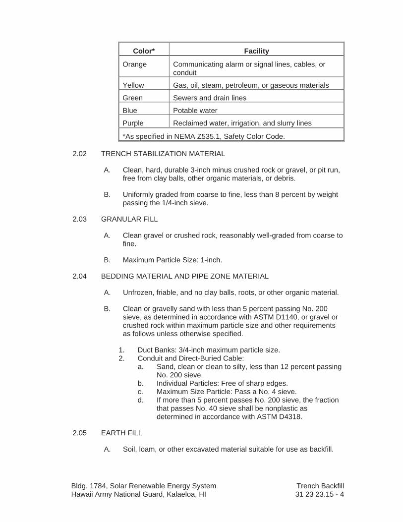
Bldg. 1784, Solar Renewable Energy System Trench Backfill Hawaii Army National Guard, Kalaeloa, HI 31 23 23.15 - 4
Color* Facility
Orange Communicating alarm or signal lines, cables, or conduit
Yellow Gas, oil, steam, petroleum, or gaseous materials
Green Sewers and drain lines
Blue Potable water
Purple Reclaimed water, irrigation, and slurry lines
*As specified in NEMA Z535.1, Safety Color Code.
2.02 TRENCH STABILIZATION MATERIAL
A. Clean, hard, durable 3-inch minus crushed rock or gravel, or pit run, free from clay balls, other organic materials, or debris.
B. Uniformly graded from coarse to fine, less than 8 percent by weight passing the 1/4-inch sieve.
2.03 GRANULAR FILL
A. Clean gravel or crushed rock, reasonably well-graded from coarse to fine.
B. Maximum Particle Size: 1-inch.
2.04 BEDDING MATERIAL AND PIPE ZONE MATERIAL
A. Unfrozen, friable, and no clay balls, roots, or other organic material.
B. Clean or gravelly sand with less than 5 percent passing No. 200 sieve, as determined in accordance with ASTM D1140, or gravel or crushed rock within maximum particle size and other requirements as follows unless otherwise specified.
1. Duct Banks: 3/4-inch maximum particle size. 2. Conduit and Direct-Buried Cable:
a. Sand, clean or clean to silty, less than 12 percent passing No. 200 sieve.
b. Individual Particles: Free of sharp edges. c. Maximum Size Particle: Pass a No. 4 sieve. d. If more than 5 percent passes No. 200 sieve, the fraction
that passes No. 40 sieve shall be nonplastic as determined in accordance with ASTM D4318.
2.05 EARTH FILL
A. Soil, loam, or other excavated material suitable for use as backfill.
Bldg. 1784, Solar Renewable Energy System Trench Backfill Hawaii Army National Guard, Kalaeloa, HI 31 23 23.15 - 5
B. Free from roots or organic matter, refuse, boulders and material larger than 1/2 cubic foot, or other deleterious materials.
2.06 CLSM
A. Select and proportion ingredients to obtain compressive strength between 50 and 150 psi at 28 days in accordance with ASTM D4832.
B. Materials:
1. Cement: ASTM C150/C150M, Type I or Type II. 2. Aggregate: ASTM C33/C33M, Size 7. 3. Fly Ash (Pozzolan): Class F or Class C fly ash in accordance
with ASTM C618, except as modified herein. a. ASTM C618, Table 1, Loss on Ignition: Unless permitted
otherwise, maximum 3 percent. 4. Water: Clean, potable, containing less than 500 ppm of
chlorides.
2.07 GRAVEL SURFACING ROCK
A. As specified in Section 32 11 23, Aggregate Base Courses.
2.08 TOPSOIL
A. As specified in Section 32 91 13, Soil Preparation.
2.09 SOURCE QUALITY CONTROL
A. Perform gradation analysis in accordance with ASTM C136 for:
1. Earth backfill, including specified class. 2. Trench stabilization material. 3. Bedding and pipe zone material.
B. Certify Laboratory Performance of Mix Designs: CLSM.
PART 3 EXECUTION
3.01 TRENCH PREPARATION
A. Water Control:
1. Promptly remove and dispose of water entering trench as necessary to grade trench bottom and to compact backfill and install manholes, pipe, conduit, direct-buried cable, or duct bank. Do not place concrete, lay pipe, conduit, direct-buried cable, or duct bank in water.
2. Remove water in a manner that minimizes soil erosion from trench sides and bottom.
3. Provide continuous water control until trench backfill is complete.

Bldg. 1784, Solar Renewable Energy System Trench Backfill Hawaii Army National Guard, Kalaeloa, HI 31 23 23.15 - 6
B. Remove foreign material and backfill contaminated with foreign material that falls into trench.
3.02 TRENCH BOTTOM
A. Firm Subgrade: Grade with hand tools, remove loose and disturbed material, and trim off high areas and ridges left by excavating bucket teeth. Allow space for bedding material if shown or specified.
B. Soft Subgrade: If subgrade is encountered that may require removal to prevent pipe settlement, notify Contracting Officer. Contracting Officer will determine depth of overexcavation, if any required.
3.03 TRENCH STABILIZATION MATERIAL INSTALLATION
A. Rebuild trench bottom with trench stabilization material.
B. Place material over full width of trench in 6-inch lifts to required grade, providing allowance for bedding thickness.
C. Compact each lift so as to provide a firm, unyielding support for the bedding material prior to placing succeeding lifts.
3.04 BEDDING
A. Furnish imported bedding material where, in the opinion of Contracting Officer, excavated material is unsuitable for bedding or insufficient in quantity.
B. Place over full width of prepared trench bottom in two equal lifts when required depth exceeds 8 inches.
C. Hand grade and compact each lift to provide a firm, unyielding surface.
D. Minimum Thickness: As follows.
1. Pipe 15 Inches and Smaller: 4 inches. 2. Conduit: 3 inches. 3. Direct-Buried Cable: 3 inches. 4. Duct Banks: 3 inches.
E. Check grade and correct irregularities in bedding material. Loosen top 1 inch to 2 inches of compacted bedding material with a rake or by other means to provide a cushion before laying each section of pipe, conduit, direct-buried cable, or duct bank.
F. Install to form continuous and uniform support except at bell holes, if applicable, or minor disturbances resulting from removal of lifting tackle.

Bldg. 1784, Solar Renewable Energy System Trench Backfill Hawaii Army National Guard, Kalaeloa, HI 31 23 23.15 - 7
G. Bell or Coupling Holes: Excavate in bedding at each joint to permit proper assembly and inspection of joint and to provide uniform bearing along barrel of pipe or conduit.
3.05 BACKFILL PIPE ZONE
A. Upper limit of pipe zone shall not be less than following:
1. Pipe: 12 inches, unless shown otherwise. 2. Conduit: 3 inches, unless shown otherwise. 3. Direct-Buried Cable: 3 inches, unless shown otherwise. 4. Duct Bank: 3 inches, unless shown otherwise.
B. Restrain pipe, conduit, cables, and duct banks as necessary to prevent their movement during backfill operations.
C. Place material simultaneously in lifts on both sides of pipe and, if applicable, between pipes, conduit, cables, and duct banks installed in same trench.
1. Pipe 10-Inch and Smaller Diameter: First lift less than or equal to 1/2 pipe diameter.
D. Thoroughly tamp each lift, including area under haunches, with handheld tamping bars supplemented by “walking in” and slicing material under haunches with a shovel to ensure voids are completely filled before placing each succeeding lift.
E. Do not use power-driven impact compactors to compact pipe zone material. After full depth of pipe zone material has been placed as specified, compact material by a minimum of three passes with a vibratory plate compactor only over area between sides of pipe and trench walls.
3.06 MARKING TAPE INSTALLATION
A. Continuously install marking tape along centerline of buried piping, on top of last lift of pipe zone material. Coordinate with piping installation drawings.
1. Detectable Marking Tape: Install with nonmetallic piping and waterlines.
3.07 BACKFILL ABOVE PIPE ZONE
A. General:
1. Process excavated material to meet specified gradation requirements.
2. Adjust moisture content as necessary to obtain specified compaction.

Bldg. 1784, Solar Renewable Energy System Trench Backfill Hawaii Army National Guard, Kalaeloa, HI 31 23 23.15 - 8
3. Do not allow backfill to free fall into trench or allow heavy, sharp pieces of material to be placed as backfill until after at least 2 feet of backfill has been provided over top of pipe.
4. Do not use power-driven impact type compactors for compaction until at least 4 feet of backfill is placed over top of pipe.
5. Backfill to grade with proper allowances for topsoil, crushed rock surfacing, and pavement thicknesses, wherever applicable.
B. CLSM:
1. Discharge from truck-mounted drum type mixer into trench. 2. Place in lifts as necessary to prevent uplift (flotation) of new and
existing facilities. 3. In traveled areas fill entire trench section to pavement finish
grade for a temporary driving surface, and screed off excess and finish with a float.
4. In other areas fill trench section as shown.
3.08 REPLACEMENT OF TOPSOIL
A. Replace topsoil in top 12 inches of backfilled trench.
B. Maintain finished grade of topsoil even with adjacent area and grade as necessary to restore drainage.
3.09 MAINTENANCE OF TRENCH BACKFILL
A. After each section of trench is backfilled, maintain surface of backfilled trench even with adjacent ground surface until final surface restoration is completed.
B. Gravel Surfacing Rock: Add gravel surfacing rock where applicable and as necessary to keep surface of backfilled trench even with adjacent ground surface, and grade and compact as necessary to keep surface of backfilled trenches smooth, free from ruts and potholes, and suitable for normal traffic flow.
C. Topsoil: Add topsoil where applicable and as necessary to maintain surface of backfilled trench level with adjacent ground surface.
D. Asphaltic Pavement: Replace settled areas or fill with asphalt as specified in Section 32 12 16, Asphalt Concrete Pavement.
E. Other Areas: Add excavated material where applicable and keep surface of backfilled trench level with adjacent ground surface.

Bldg. 1784, Solar Renewable Energy System Trench Backfill Hawaii Army National Guard, Kalaeloa, HI 31 23 23.15 - 9
3.10 SETTLEMENT OF BACKFILL
A. Settlement of trench backfill, or of fill, or facilities constructed over trench backfill will be considered a result of defective compaction of trench backfill.
END OF SECTION

Bldg. 1784, Solar Renewable Energy System Aggregate Base Courses Hawaii Army National Guard, Kalaeloa, HI 32 11 23 - 1
SECTION 32 11 23 – AGGREGATE BASE COURSES
PART 1 GENERAL
1.01 REFERENCES
A. The following is a list of standards that may be referenced in this section:
1. American Association of State Highway and Transportation Officials (AASHTO): a. T11, Standard Method of Test for Materials Finer Than
75 m (No. 200) Sieve in Mineral Aggregates by Washing. b. T27, Standard Method of Test for Sieve Analysis of Fine
and Coarse Aggregates. c. T89, Standard Specification for Determining the Liquid
Limit of Soils. d. T90, Standard Specification for Determining the Plastic
Limit and Plasticity Index of Soils. e. T96, Standard Specification for Resistance to Degradation
of Small-Size Coarse Aggregate by Abrasion and Impact in the Los Angeles Machine.
f. T99, Standard Specification for the Moisture-Density Relations of Soils Using a 2.5 kg (5.5 pound) Rammer and a 305 mm (12 in) Drop.
g. T180, Standard Specification for Moisture-Density Relations of Soils Using a 4.54 kg (10-lb) Rammer and a 457 mm (18-in) Drop.
h. T190, Standard Specification for Resistance R-Value and Expansion Pressure of Compacted Soils.
i. T265, Standard Method of Test for Laboratory Determination of Moisture Content of Soils.
j. T310, Standard Specification for In-Place Density and Moisture Content of Soil and Soil-Aggregate by Nuclear Methods (Shallow Depth).
2. ASTM International (ASTM): a. C88, Test Method for Soundness of Aggregates by Use of
Sodium Sulfate or Magnesium Sulfate. b. D1883, Test Method for CBR (California Bearing Ratio) of
Laboratory Compacted Soils. c. D2419, Test Method for Sand Equivalent Value of Soils
and Fine Aggregate. d. D4791, Test Method for Flat Particles, Elongated
Particles, or Flat and Elongated Particles in Coarse Aggregate.

Bldg. 1784, Solar Renewable Energy System Aggregate Base Courses Hawaii Army National Guard, Kalaeloa, HI 32 11 23 - 2
1.02 DEFINITIONS
A. Completed Course: Compacted, unyielding, free from irregularities, with smooth, tight, even surface, true to grade, line, and cross-section.
B. Completed Lift: Compacted with uniform cross-section thickness.
C. Standard Specifications: Standard Specifications for Public Works Construction, September 1986, Departments of Public Works County of Kauai, City and County of Honolulu, County of Maui, County of Hawaii of the State of Hawaii.
1.03 SUBMITTALS
A. Informational Submittals:
1. Certified Test Results on Source Materials: Submit copies from commercial testing laboratory 20 days prior to delivery of materials to Project showing materials meeting the physical qualities specified.
2. Certified results of in-place density tests from independent testing agency.
PART 2 PRODUCTS
2.01 BASE COURSE
A. As specified for 3/4-inch maximum in Section 31 of the Standard Specifications.
2.02 SOURCE QUALITY CONTROL
A. Perform tests necessary to locate acceptable source of materials meeting specified requirements.
B. Final approval of aggregate material will be based on test results of installed materials.
C. Should separation of coarse from fine materials occur during processing or stockpiling, immediately change methods of handling materials to correct uniformity in grading.
PART 3 EXECUTION
3.01 SUBGRADE PREPARATION
A. As specified in Section 31 23 13, Subgrade Preparation.
B. Obtain Contracting Officer’s acceptance of subgrade before placing base course or surfacing material.
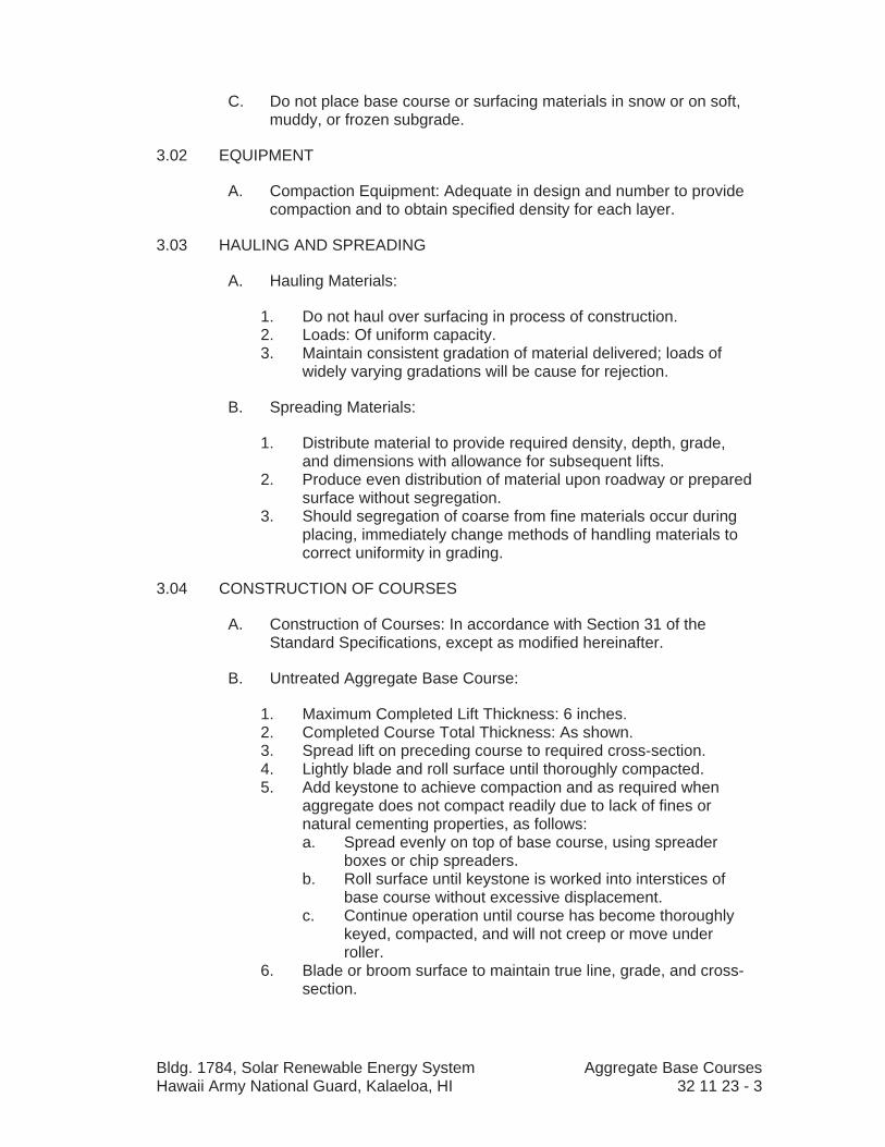
Bldg. 1784, Solar Renewable Energy System Aggregate Base Courses Hawaii Army National Guard, Kalaeloa, HI 32 11 23 - 3
C. Do not place base course or surfacing materials in snow or on soft, muddy, or frozen subgrade.
3.02 EQUIPMENT
A. Compaction Equipment: Adequate in design and number to provide compaction and to obtain specified density for each layer.
3.03 HAULING AND SPREADING
A. Hauling Materials:
1. Do not haul over surfacing in process of construction. 2. Loads: Of uniform capacity. 3. Maintain consistent gradation of material delivered; loads of
widely varying gradations will be cause for rejection.
B. Spreading Materials:
1. Distribute material to provide required density, depth, grade, and dimensions with allowance for subsequent lifts.
2. Produce even distribution of material upon roadway or prepared surface without segregation.
3. Should segregation of coarse from fine materials occur during placing, immediately change methods of handling materials to correct uniformity in grading.
3.04 CONSTRUCTION OF COURSES
A. Construction of Courses: In accordance with Section 31 of the Standard Specifications, except as modified hereinafter.
B. Untreated Aggregate Base Course:
1. Maximum Completed Lift Thickness: 6 inches. 2. Completed Course Total Thickness: As shown. 3. Spread lift on preceding course to required cross-section. 4. Lightly blade and roll surface until thoroughly compacted. 5. Add keystone to achieve compaction and as required when
aggregate does not compact readily due to lack of fines or natural cementing properties, as follows: a. Spread evenly on top of base course, using spreader
boxes or chip spreaders. b. Roll surface until keystone is worked into interstices of
base course without excessive displacement. c. Continue operation until course has become thoroughly
keyed, compacted, and will not creep or move under roller.
6. Blade or broom surface to maintain true line, grade, and cross-section.

Bldg. 1784, Solar Renewable Energy System Aggregate Base Courses Hawaii Army National Guard, Kalaeloa, HI 32 11 23 - 4
3.05 ROLLING AND COMPACTION
A. In accordance with Section 31 of the Standard Specifications, exceptas modified hereinafter.
B. Roll each layer of material until material does not creep under roller before succeeding layer is applied.
C. Commence rolling at outer edges and continue toward center; do not roll center of road first.
D. Apply water as needed to obtain specified densities.
E. Place and compact each lift to required density before succeeding lift is placed.
F. Surface Defects: Remedy by loosening and rerolling. Reroll entire area, including surrounding surface, until thoroughly compacted.
G. Finished surface shall be true to grade and crown before proceeding with surfacing.
3.06 SURFACE TOLERANCES
A. Blade or otherwise work surfacing as necessary to maintain grade and cross-section at all times, and to keep surface smooth and thoroughly compacted.
B. Finished Surface of Untreated Aggregate Base Course: Within plus or minus 0.04 foot of grade shown at any individual point.
C. Overall Average: Within plus or minus 0.01 foot from crown and grade specified.
3.07 FIELD QUALITY CONTROL
A. In-Place Density Tests:
1. Provide testing laboratory at least 2 days advance notification prior to testing.
2. Show proof that areas meet specified requirements before identifying density test locations.
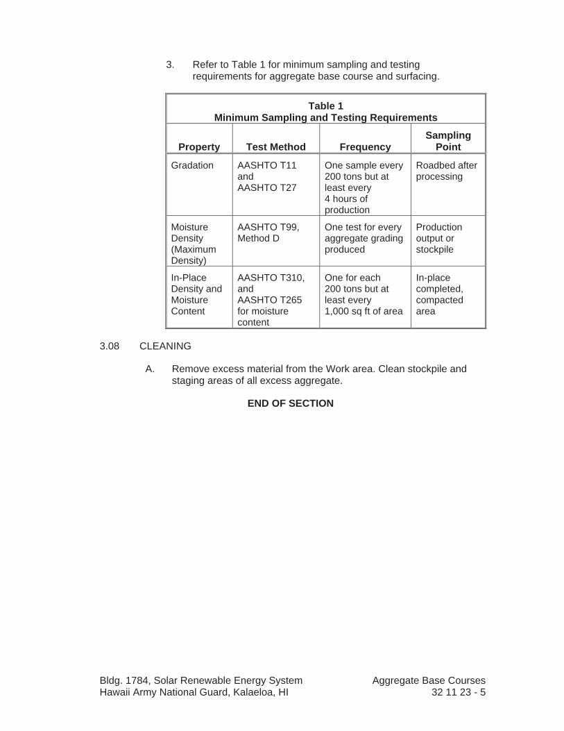
Bldg. 1784, Solar Renewable Energy System Aggregate Base Courses Hawaii Army National Guard, Kalaeloa, HI 32 11 23 - 5
3. Refer to Table 1 for minimum sampling and testing requirements for aggregate base course and surfacing.
Table 1 Minimum Sampling and Testing Requirements
Property Test Method FrequencySampling
Point
Gradation AASHTO T11 andAASHTO T27
One sample every 200 tons but at least every 4 hours of production
Roadbed after processing
MoistureDensity(MaximumDensity)
AASHTO T99, Method D
One test for every aggregate grading produced
Productionoutput or stockpile
In-PlaceDensity and MoistureContent
AASHTO T310, andAASHTO T265 for moisture content
One for each 200 tons but at least every 1,000 sq ft of area
In-placecompleted,compactedarea
3.08 CLEANING
A. Remove excess material from the Work area. Clean stockpile and staging areas of all excess aggregate.
END OF SECTION

Bldg. 1784, Solar Renewable Energy System Asphalt Concrete Pavement Hawaii Army National Guard, Kalaeloa, HI 32 12 16 - 1
SECTION 32 12 16 – ASPHALT CONCRETE PAVEMENT
PART 1 GENERAL
1.01 REFERENCES
A. The following is a list of standards that may be referenced in this section:
1. American Association of State Highway and Transportation Officials (AASHTO): a. M17, Standard Specification for Mineral Filler for
Bituminous Paving Mixtures. b. M81, Standard Specification for Cut-Back Asphalt (Rapid
Curing Type). c. M82, Standard Specification for Cut-Back Asphalt
(Medium Curing Type). d. M140, Standard Specification for Emulsified Asphalt. e. M208, Standard Specification for Cationic Emulsified
Asphalt.f. T166, Standard Method of Test for Bulk Specific Gravity of
Compacted Asphalt Mixtures Using Saturated Surface-Dry Specimens.
g. T176 Standard Method of Test for Plastic Fines in Graded Aggregates and Soils by Use of the Sand Equivalent Test.
h. T230, Standard Method of Test for Determining Degree of Pavement Compaction of Bituminous Aggregate Mixtures.
i. T245, Standard Method of Test for Resistance to Plastic Flow of Bituminous Mixtures Using Marshall Apparatus.
j. T246, Standard Method of Test for Resistance to Deformation and Cohesion of Bituminous Mixtures by Means of Hveem Apparatus.
k. T247, Standard Method of Test for Preparation of Test Specimens of Bituminous Mixtures by Means of California Kneading Compactor.
l. T283, Standard Method of Test for Resistance of Compacted Bituminous Mixture to Moisture Induced Damage.
m. T304, Standard Method of Test for Uncompacted Void Content of Fine Aggregate (Method A).
2. Asphalt Institute (AI): a. Manual Series No. 2 (MS-2), Mix Design Methods for
Asphalt Concrete. b. Superpave Series No. 2 (SP-2), Superpave Mix Design.
3. ASTM International (ASTM): a. D2041, Test Method for Theoretical Maximum Specific
Gravity and Density of Bituminous Paving Mixtures. b. D4318, Test Methods for Liquid Limit, Plastic Limit, and
Plasticity Index of Soils.

Bldg. 1784, Solar Renewable Energy System Asphalt Concrete Pavement Hawaii Army National Guard, Kalaeloa, HI 32 12 16 - 2
c. D4791, Test Method for Flat Particles, Elongated Particles, or Flat and Elongated Particles in Coarse Aggregate.
d. D5821, Test Method for Determining the Percentage of Fractured Particles in Coarse Aggregate.
e. E329, Specification for Agencies Engaged in the Testing and/or Inspection of Materials Used in Construction.
4. Standard Specifications: Standard Specifications for Public Works Construction, September 1986, Departments of Public Works County of Kauai, City and County of Honolulu, County of Maui, County of Hawaii of the State of Hawaii.
1.02 DEFINITIONS
A. Combined Aggregate: All mineral constituents of asphalt concrete mix, including mineral filler and separately sized aggregates.
B. RAP: Reclaimed asphalt pavement.
C. Standard Specifications: Standard Specifications for Public Works Construction, September 1986, Departments of Public Works County of Kauai, City and County of Honolulu, County of Maui, County of Hawaii of the State of Hawaii.
1.03 DESIGN REQUIREMENTS
A. Prepare asphalt concrete mix design, meeting the following design criteria, tolerances, and other requirements of this Specification and the Standard Specifications.
1.04 SUBMITTALS
A. Informational Submittals:
1. Asphalt Concrete Mix Formula: a. Submit minimum of 15 days prior to start of production. b. Submittal to include the following information:
1) Gradation and portion for each aggregate constituent used in mixture to produce a single gradation of aggregate within specified limits.
2) Bulk specific gravity for each aggregate constituent. 3) Measured maximum specific gravity of mix at
optimum asphalt content determined in accordance with ASTM D2041.
4) Properties as stated in Section 34 of the Standard Specifications, for at least four different asphalt contents other than optimum, two below optimum, and two above optimum.
5) Percent of asphalt lost due to absorption by aggregate.
6) Index of retained strength (TSR) at optimum asphalt content as determined by AASHTO T283.

Bldg. 1784, Solar Renewable Energy System Asphalt Concrete Pavement Hawaii Army National Guard, Kalaeloa, HI 32 12 16 - 3
7) Percentage of asphalt cement, to nearest 0.1 percent, to be added to mixture.
8) Optimum mixing temperature. 9) Optimum compaction temperature. 10) Temperature-viscosity curve of asphalt cement to be
used.11) Brand name of any additive to be used and
percentage added to mixture. 2. Test Report for Asphalt Cement:
a. Submit minimum 10 days prior to start of production. b. Show appropriate test method(s) for each material and the
test results. 3. Manufacturer’s Certificate of Compliance for the following
materials: a. Aggregate: Gradation, source test results as defined in
Section 34 of the Standard Specifications. b. Asphalt for Binder: Type, grade, and viscosity-temperature
curve. c. Tack Coat: Type and grade of asphalt. d. Additives. e. Mix: Conforms to job-mix formula.
4. Statement of qualification for independent testing laboratory. 5. Test Results:
a. Mix design. b. Asphalt concrete core. c. Gradation and asphalt content of uncompacted mix.
1.05 QUALITY ASSURANCE
A. Qualifications:
1. Independent Testing Laboratory: In accordance with ASTM E329. 2. Asphalt concrete mix formula shall be prepared by approved
certified independent laboratory under the supervision of a certified asphalt technician.
1.06 ENVIRONMENTAL REQUIREMENTS
A. Temperature: Do not apply asphalt materials or place asphalt mixes when ground temperature is lower than 10 degrees C (50 degrees F) or air temperature is lower than 4 degrees C (40 degrees F). Measure ground and air temperature in shaded areas away from heat sources or wet surfaces.
B. Moisture: Do not apply asphalt materials or place asphalt mixes when application surface is wet.

Bldg. 1784, Solar Renewable Energy System Asphalt Concrete Pavement Hawaii Army National Guard, Kalaeloa, HI 32 12 16 - 4
PART 2 PRODUCTS
2.01 MATERIALS
A. Tack Coat: Emulsified asphalt, conform to Section 34 of the Standard Specifications.
B. Sand (Blotter Material): As specified in Section 34 of the Standard Specifications.
2.02 ASPHALT CONCRETE MIX
A. General:
1. Mix formula shall not be modified except with written approval of Contracting Officer.
2. Source Changes: a. Should material source(s) change, establish new asphalt
concrete mix formula before new material(s) is used. b. Perform check tests of properties of plant-mix bituminous
materials on first day of production and as requested by Contracting Officer to confirm that properties are in compliance with design criteria.
c. Make adjustments in gradation or asphalt content as necessary to meet design criteria.
B. Asphalt: Grade AR-4000 or AR-800, as specified in Section 34 of the Standard Specifications.
C. Composition: Hot-plant mix of aggregate, mineral filler if required, and paving grade asphalt cement. The several aggregate fractions shall be sized, uniformly graded, and combined in such proportions that resulting mixture meets grading requirements of mix formula.
D. Aggregate:
1. General: As specified in Section 34 of the Standard Specifications.
E. Mineral Filler: In accordance with Section 34 of the Standard Specifications.
PART 3 EXECUTION
3.01 GENERAL
A. Traffic Control: Minimize inconvenience to traffic, but keep vehicles off freshly treated or paved surfaces to avoid pickup and tracking of asphalt.
Bldg. 1784, Solar Renewable Energy System Asphalt Concrete Pavement Hawaii Army National Guard, Kalaeloa, HI 32 12 16 - 5
3.02 LINE AND GRADE
A. Provide and maintain intermediate control of line and grade, independent of underlying base, to meet finish surface grades and minimum thickness.
B. Shoulders: Construct to line, grade, and cross-section shown.
3.03 APPLICATION EQUIPMENT
A. In accordance with Section 34 of the Standard Specifications.
3.04 PREPARATION
A. Prepare subgrade as specified in Section 31 23 13, Subgrade Preparation.
B. Thoroughly coat edges of contact surfaces (curbs, manhole frames) with emulsified asphalt or asphalt cement prior to laying new pavement. Prevent staining of adjacent surfaces.
3.05 PAVEMENT APPLICATION
A. General: Place asphalt concrete mixture on approved, prepared base in conformance with Section 34 of the Standard Specifications.
B. Tack Coat:
1. Prepare material, as specified in Section 34 of the Standard Specifications, prior to application.
2. Apply uniformly to clean, dry surfaces avoiding overlapping of applications.
3. Do not apply more tack coat than necessary for the day’s paving operation.
4. Touch up missed or lightly coated surfaces and remove excess material.
5. Application Rate: Minimum 0.25 liter to maximum 0.70 liter of asphalt (residual if diluted emulsified asphalt) per square meter (0.05 to 0.15 gallon per square yard) of surface area.
C. Pavement Mix:
1. Prior to Paving: a. Sweep surface free of dirt, dust, or other foreign matter. b. Patch holes in surface with asphalt concrete pavement
mix. 2. Place asphalt concrete pavement mix in two equal lifts. 3. Compacted Lift Thickness:
a. Minimum: Twice maximum aggregate size, but in no case less than 25 millimeters (1 inch).
b. Maximum: 62.5 millimeters (2-1/2 inches). 4. Total Compacted Thickness: As shown.

Bldg. 1784, Solar Renewable Energy System Asphalt Concrete Pavement Hawaii Army National Guard, Kalaeloa, HI 32 12 16 - 6
5. Apply such that meet lines are straight and edges are vertical. 6. Collect and dispose of segregated aggregate from raking
process. Do not scatter material over finished surface. 7. Joints:
a. Offset edge of each layer a minimum of 150 millimeters (6 inches) so joints are not directly over those in underlying layer.
b. Offset longitudinal joints in roadway pavements so longitudinal joints in wearing layer coincide with pavement centerlines and lane divider lines.
c. Form transverse joints by cutting back on previous day’s run to expose full vertical depth of layer.
8. Succeeding Lifts: Apply tack coat to pavement surface between each lift.
9. After placement of pavement, seal meet line by painting a minimum of 150 millimeters (6 inches) on each side of joint with cut-back or emulsified asphalt. Cover immediately with sand.
D. Compaction:
1. Uniformly compact each course to target density arrived at in compaction control strip.
2. Uniformly compact each course until there is no further evidence of consolidation and roller marks are eliminated. When placement rate exceeds 90 Mg (100 tons) per hour, operate minimum of two rollers for compaction.
3. Roll until roller marks are eliminated and minimum percent compaction as stated in the Standard Specifications.
4. Joint Compaction: a. Place top or wearing layer as continuously as possible. b. Cut back previously compacted mixture when Work is
resumed to produce slightly beveled edge for full thickness of layer.
c. Cut away waste material and lay new mix against fresh cut.
E. Tolerances:
1. General: Conduct measurements for conformity with crown and grade immediately after initial compression. Correct variations immediately by removal or addition of materials and by continuous rolling.
2. Completed Surface or Wearing Layer Smoothness: a. Uniform texture, smooth, and uniform to crown and grade. b. Maximum Deviation: 3 millimeters (1/8 inch) from lower
edge of a 3.6-meter (12-foot) straightedge, measured continuously parallel and at right angle to centerline.
c. If surface of completed pavement deviates by more than twice specified tolerances, remove and replace wearing surface.

Bldg. 1784, Solar Renewable Energy System Asphalt Concrete Pavement Hawaii Army National Guard, Kalaeloa, HI 32 12 16 - 7
3. Transverse Slope Maximum Deviation: 6 millimeters (1/4 inch) in 3.6 meters (12 feet) from rate of slope shown.
4. Finished Grade: a. Perform field differential level survey on maximum
15-meter (50-foot) meter grid and along grade breaks. b. Maximum Deviation: 6 millimeters (0.02 foot) from grade
shown.
3.06 PATCHING
A. Preparation:
1. Remove damaged, broken, or unsound asphalt concrete adjacent to patches. Trim to straight lines exposing smooth, sound, vertical edges.
2. Prepare patch subgrade as specified in Section 31 23 13, Subgrade Preparation.
B. Application:
1. Patch Thickness: 75 millimeters (3 inches) or thickness of adjacent asphalt concrete, whichever is greater.
2. Place asphalt concrete mix across full width of patch in layers of equal thickness.
3. Spread and grade asphalt concrete with hand tools or mechanical spreader, depending on size of area to be patched.
C. Compaction:
1. Roll patches with power rollers capable of providing compression of 350 to 525 Newtons per linear centimeter (200 to 300 pounds per linear inch). Use hand tampers where rolling is impractical.
2. Begin rolling top course at edges of patches, lapping adjacent asphalt surface at least 1/2 the roller width. Progress toward center of patch overlapping each preceding track by at least 1/2 width of roller.
3. Make sufficient passes over entire area to remove roller marks and to produce desired finished surface.
D. Tolerances:
1. Finished surface shall be flush with and match grade, slope, and crown of adjacent surface.
2. Tolerance: Surface smoothness shall not deviate more than plus 6 millimeters (1/4 inch) or minus 0 millimeter when straightedge is laid across patched area between edges of new pavement and surface of old surfacing.

Bldg. 1784, Solar Renewable Energy System Asphalt Concrete Pavement Hawaii Army National Guard, Kalaeloa, HI 32 12 16 - 8
3.07 FIELD QUALITY CONTROL
A. General: Provide services of approved certified independent testing laboratory to conduct tests.
B. Field Density Tests:
1. Perform tests from cores or sawed samples in accordance with AASHTO T230 and AASHTO T166.
2. Measure with properly operating and calibrated nuclear density gauge in accordance with ASTM D2950.
3. Maximum Density: In accordance with ASTM D2041, using sample of mix taken prior to compaction from same location as density test sample.
C. Testing Frequency:
1. Quality Control Tests: a. Asphalt Content, Aggregate Gradation: Once per every
200 tons of mix or once every 4 hours, whichever is greater.
b. Mix Design Properties, Measured Maximum (Rice’s) Specific Gravity: Once every 200 tons or once every 8 hours, whichever is greater.
2. Density Tests: Once every 200 tons of mix or once every 4 hours, whichever is greater.
END OF SECTION

Bldg. 1784, Solar Renewable Energy System Soil Preparation Hawaii Army National Guard, Kalaeloa, HI 32 91 13 - 1
SECTION 32 91 13 – SOIL PREPARATION
PART 1 GENERAL
1.01 REFERENCES
A. The following is a list of standards that may be referenced in this section:
1. ASTM International (ASTM): a. C33/C33M, Standard Specification for Concrete
Aggregates.b. C602, Standard Specification for Agricultural Liming
Materials. c. D2974, Standard Test Methods for Moisture, Ash, and
Organic Matter of Peat and Other Organic Soils. d. D5268, Standard Specification for Topsoil Used for
Landscaping Purposes.
1.02 SEQUENCING AND SCHEDULING
A. Perform Work specified in Section 31 10 00, Site Clearing, prior to performing Work specified under this section.
PART 2 PRODUCTS
2.01 TOPSOIL
A. General: Natural, friable, sandy loam, obtained from well-drained areas, free from objects larger than 1-1/2 inches maximum dimension, and free of subsoil, roots, grass, other foreign matter, hazardous or toxic substances, and deleterious material that may be harmful to plant growth or may hinder grading, planting, or maintenance.
B. Composition: In general accordance with ASTM D5268:
1. Gravel-Sized Fraction: Maximum 5 percent by weight retained on a No. 10 sieve.
2. Sand-Sized Fraction: Minimum 20 to 60 percent passing No. 10 sieve.
3. Silt and Clay-Sized Fraction: Minimum 35 to 70 percent.
C. Organic Matter: Minimum 1.5 percent by dry weight as determined in accordance with ASTM D2974.
D. pH: Range 5.0 to 7.0.
E. Textural Amendments: Amend as necessary to conform to required composition by incorporating sand, peat, manure, or sawdust.

Bldg. 1784, Solar Renewable Energy System Soil Preparation Hawaii Army National Guard, Kalaeloa, HI 32 91 13 - 2
F. Source: Stockpile material onsite, in accordance with Section 31 10 00, Site Clearing. Import topsoil if onsite material is insufficient in quantity.
2.02 LIME
A. Composition: Ground limestone with not less than 85 percent total carbonates, ASTM C602.
B. Gradation:
1. Minimum 50 percent passing No. 100 sieve. 2. Minimum 90 percent passing No. 20 sieve. 3. Coarser material acceptable provided rates of application are
increased proportionately on basis of quantities passing No. 100 sieve.
2.03 ORGANIC SOIL CONDITIONERS
A. As specified in Section 32 92 00, Lawns and Grasses.
2.04 FERTILIZER
A. As specified in Section 32 92 00, Lawns and Grasses.
2.05 SAND
A. Fine Aggregate: Clean, coarse, well-graded, ASTM C33/C33M.
PART 3 EXECUTION
3.01 SUBGRADE PREPARATION
A. Apply lime at the rate of 50 pounds per 1,000 square feet to subgrade before tilling.
B. Scarify subgrade to minimum depth of 6 inches where topsoil is to be placed.
C. Remove stones over 2-1/2 inches in any dimension, sticks, roots, rubbish, and other extraneous material.
D. Limit preparation to areas that will receive topsoil within 2 days after preparation.
3.02 TOPSOIL PLACEMENT
A. Do not place topsoil when subsoil or topsoil is frozen, excessively wet, or otherwise detrimental to the Work.

Bldg. 1784, Solar Renewable Energy System Soil Preparation Hawaii Army National Guard, Kalaeloa, HI 32 91 13 - 3
B. Place one-half of the total depth of topsoil and work into top 3 inches of subgrade soil to create a transition layer. Place remainder of topsoil minimum depth of 6 inches where seeding and planting are scheduled.
C. Uniformly distribute to within 1/2 inch of final grades. Fine grade topsoil eliminating rough or low areas and maintaining levels, profiles, and contours of subgrade.
D. Remove stones exceeding 1-1/2-inch diameter, roots, sticks, debris, and foreign matter during and after topsoil placement.
E. Remove surplus subsoil and topsoil from Site. Grade stockpile area as necessary and place in condition acceptable for planting or seeding.
END OF SECTION

Bldg. 1784, Solar Renewable Energy System Lawns and Grasses Hawaii Army National Guard, Kalaeloa, HI 32 92 00 - 1
SECTION 32 92 00 – LAWNS AND GRASSES
PART 1 GENERAL
1.01 REFERENCES
A. Standard Specifications for Public Works Construction, September 1986, Departments of Public Works, County of Kauai, City and County of Honolulu, County of Maui, County of Hawaii of the State of Hawaii.
1.02 GENERAL REQUIREMENTS
A. Furnish all labor, materials, equipment and tools for grass planting as specified herein. Grass shall be planted in areas indicated on the drawings and as listed below.
1. All existing grassed areas that are damaged by construction operations.
2. Areas that are dug up for utility trenches. 3. Areas from which existing structures are to be removed. 4. Areas that are graded and areas used for temporary stockpile.
1.03 SUBMITTALS
A. Action Submittals: Product labels/data sheets.
B. Informational Submittals:
1. Seed; Certification of Seed Analysis, Germination Rate, and Inoculation: a. Certify that each lot of seed has been tested by a testing
laboratory certified in seed testing, within 6 months of date of delivery. Include with certification: 1) Name and address of laboratory. 2) Date of test. 3) Lot number for each seed specified. 4) Test Results: i) name, ii) percentages of purity and
of germination, and iii) weed content for each kind of seed furnished.
b. Mixtures: Proportions of each kind of seed.
1.04 DELIVERY, STORAGE AND PROTECTION
A. Seed:
1. Furnish in standard containers with seed name, lot number, net weight, percentages of purity, germination, and hard seed and maximum weed seed content, clearly marked for each container of seed.
2. Keep dry during storage.

Bldg. 1784, Solar Renewable Energy System Lawns and Grasses Hawaii Army National Guard, Kalaeloa, HI 32 92 00 - 2
B. Hydroseeding Mulch: Mark package of wood fiber mulch to show air-dry weight.
1.05 WEATHER RESTRICTIONS
A. Perform Work under favorable weather and soil moisture conditions as determined by accepted local practice.
PART 2 PRODUCTS
2.01 FERTILIZER
A. Commercial, pelletized, 6-6-6 or equal, uniform in composition, free-flowing, suitable for application with equipment designed for that purpose. Minimum percentage of plant food by weight.
B. Application Rates: As recommended by manufacturer.
2.02 SEED
A. Grass shall be “Manienie”, on flat areas less than 3:1 slope, or fine Bermuda grass (Cynodon Dactylon). At the option of the Contractor, grass planting may be by seeds (plain seeding or by hydro-mulching) or by sprigs.
1. Grass seeds shall be fresh, hulled, and meet the following requirements:a. Pure Seed: 95.0 percent minimum. b. Crop Seed: 1.0 percent maximum. c. Weed: 0.5 percent maximum. d. Inert Material: 5.0 percent maximum. e. Germination: 85.0 percent minimum.
2. Grass seeds shall be delivered to the site in unopened, sealed containers, labeled with the brand name and percent purity. Labeling shall indicate that the seeds passed a certified germination test no more than 12 months prior to use.
3. Grass sprigs shall be healthy, living runners and stolons, a minimum of 6 inches long with at least 3 nodes. After they are dug, the sprigs shall be covered and kept moist until planted.
2.03 HYDROSEEDING MULCH
A. Wood Cellulose Fiber Mulch:
1. Specially processed wood fiber containing no growth or germination-inhibiting factors.
2. Manufactured such that after addition and agitation in slurry tanks with water, the material fibers will become uniformly suspended to form homogenous slurry.
3. When hydraulically sprayed on ground, material will allow absorption and percolation of moisture.

Bldg. 1784, Solar Renewable Energy System Lawns and Grasses Hawaii Army National Guard, Kalaeloa, HI 32 92 00 - 3
4. Stabilizing and water retaining agent for hydro-mulching option only shall be “Verdyol Super,” “Ecology Control M-Binder” or approved equal. Rate of application of “Verdyol Super” shall be 50 pounds per acre and that for “Ecology Control M-Binder” shall be 60 pounds per acre.
2.04 TACKIFIER
A. Derived from natural organic plant sources containing no growth or germination-inhibiting materials.
1. Capable of hydrating in water, and to readily blend with other slurry materials.
2. Wood Cellulose Fiber: Add as tracer, at rate of 150 pounds per acre.
3. Manufacturers and Products: a. Chevron Asphalt Co.; CSS 1. b. Terra; Tack AR. c. J Tack; Reclamare.
2.05 FENCE
A. 2-inch by 2-inch posts 4 feet high, spaced 10 feet on center, and strung with single strand of No. 12 gauge wire marked with cloth strips at 3-foot intervals.
PART 3 EXECUTION
3.01 PREPARATION
A. Grade areas to smooth, even surface with loose, uniformly fine texture.
1. Roll and rake, remove ridges, fill depressions to meet finish grades.
2. Limit such Work to areas to be planted within immediate future. 3. Remove debris, and stones larger than 1-1/2-inch diameter, and
other objects that may interfere with planting and maintenance operations.
B. Moisten prepared areas before planting if soil is dry. Water thoroughly and allow surface to dry off before seeding. Do not create muddy soil.
C. Restore prepared areas to specified condition if eroded or otherwise disturbed after preparation and before planting.

Bldg. 1784, Solar Renewable Energy System Lawns and Grasses Hawaii Army National Guard, Kalaeloa, HI 32 92 00 - 4
3.02 PLANTING
A. The Contractor shall notify the Contracting Officer 1 day before planting of grass.
1. Immediately prior to planting operations, all planting areas shall be cleared of weeds, debris, rocks over 1 inch in diameter and clumps of earth that will not break up.
2. Option by Grass Seeding: If grass seeds are used, the following procedure shall be used (Note: Contractor should exercise caution in seeding slopes where seeds may be washed away): a. The grass seeds shall be broadcast uniformly by hand or
by sowing equipment at the rate of 100 pounds per acre. Half the seeds shall be sown with the sower moving in one direction and the remainder shall be sown at right angles to the first direction.
b. The surface shall then be raked to a smooth even plane while the seeds are simultaneously worked into the soil to a depth of about 1/2 inch.
c. The surface shall then be smoothed and compacted by means of a culti-packer, roller or other similar equipment weighing 60 to 90 pounds per lineal foot of roller.
d. The planted area shall then be watered sufficiently to provide water penetration to a depth of at least 2 inches and shall then be kept moist until roots are established.
3. Option by Grass Sprigging: a. Furrows shall be placed perpendicular to drainage aisles
and parallel to contours on slopes and shall be spaced no more than 4 inches apart.
b. Fresh sprigs shall be planted in each furrow a maximum of 6 inches apart and covered with soil to a minimum depth of 2 inches.
c. The surface shall then be smoothed and compacted by means of a culti-packer, roller or other similar equipment weighing 60 to 90 pounds per lineal foot of roller.
d. The planted areas shall be watered immediately after rolling in sufficient quantity to provide water penetration to a depth of at least 2 inches and shall then be kept moist until roots are established.
e. The area shall then be overseeded with annual rye grass seeds at the rate of 25 pounds per acre.
4. Option by Hydro-Mulching of Grass Seed: This work shall consist of furnishing and applying hulled Bermuda seed, fertilizer, mulch, and stabilizing and water-retaining agent by hydro-mulching. a. The seeds shall be applied at the rate of 100 pounds per
acre minimum. Mulch shall be applied at a rate of 1,500 pounds per acre minimum (31 pounds per 900 square feet). In every application, complete and uniform coverage of the soil shall be attained.

Bldg. 1784, Solar Renewable Energy System Lawns and Grasses Hawaii Army National Guard, Kalaeloa, HI 32 92 00 - 5
b. Application of fertilizer shall be included with mulch and seed.
c. The hydro-mulch equipment shall be capable of mixing all necessary ingredients to a uniform mixture and to apply the slurry to provide uniform coverage. Seed, fertilizer, mulch mix, and stabilizing water-retaining agent shall be applied in one operation by hydraulic equipment made specifically for this use. The equipment shall have a built-in agitation system with an operating capacity sufficient to keep the mix in uniform distribution until pumped from the tank. Distribution and discharge lines shall be large enough to prevent stoppage and shall be equipped with hydraulic discharge spray nozzles, which provide a uniform distribution of the slurry.
d. Areas inaccessible to hydro-mulching application shall be seeded or hand sprigged and fertilized by approved hand methods.
e. Water shall be applied immediately following mulching and the planted area shall then be kept moist until roots are established.
3.03 FERTILIZER
A. The Contractor shall notify the Contracting Officer 1 day before application of fertilizer.
1. Fertilizer shall be distributed uniformly over the planted area. 2. The fertilizer shall be applied about 1 week before the end of the
maintenance period and shall be followed by watering.
3.04 FIELD QUALITY CONTROL
A. 8 weeks after seeding is complete and on written notice from Contractor, Contracting Officer will, within 15 days of receipt, determine if a satisfactory stand has been established. A satisfactory stand is defined as:
1. No bare spots larger than 3 square feet. 2. Not more than 10 percent of total area with bare spots larger
than 1 square foot. 3. Not more than 15 percent of total area with bare spots larger
than 6 square inches.
B. If a satisfactory stand has not been established, Contracting Officer will make another determination after written notice from Contractor following the next growing season.

Bldg. 1784, Solar Renewable Energy System Lawns and Grasses Hawaii Army National Guard, Kalaeloa, HI 32 92 00 - 6
3.05 PROTECTION
A. Protect from pedestrian traffic by erecting temporary fence around each newly-seeded area.
END OF SECTION