Embed Size (px)
Citation preview
Prepared by: Mithun PalCivil/Structural Engineer
March 05, 2013
Prepared by: Mithun PalCivil/Structural Engineer
March 05, 2013
BP-WND Project – Blast Resistant DesignSingle Degree of Freedom System (SDOF) BP-WND Project – Blast Resistant DesignSingle Degree of Freedom System (SDOF)
Blast Resistant Design2
CONTENTSCONTENTSo Introductiono Objective of Blast Resistance Designo Types of Blast Resistance Structureso Design Process Diagramo Basic Design Informationo Design Processo References

Blast Resistant Design3
INTRODUCTIONINTRODUCTION
• Explosion is a phenomenon associate with sudden release of energy causing shock wave or pressure wave.
TYPES OF EXPLOSIONTYPES OF EXPLOSION• Nuclear Explosion• Chemical High Explosive• Accidental Explosions
TYPES OF EXPLOSION IN PETROCHEMICAL FACILITIESTYPES OF EXPLOSION IN PETROCHEMICAL FACILITIES• Vapor Cloud Explosion (VCE)• Pressure Vessel Explosion• Condensate Phase Explosion• Dust Explosion

Blast Resistant Design4
OBJECTIVE OF BLAST RESISTANT DESIGNOBJECTIVE OF BLAST RESISTANT DESIGN• Personal safety• Controlled shutdown• Financial consideration TYPE OF STRUCTURESTYPE OF STRUCTURES
Types of Construction Side-on Overpressure (Pso) Remarks
Conventional ConstructionBuildings designed for
D+L+W/EPso < 1.0psi With minor enhancement on windows,
connections
Enhanced Pre-engineering Metal Buildings 1.0< Pso < 3 psi Steel frame with cold-formed steel panels on
girts & purlins
Reinforced Masonry Clad Buildings Pso order of 3 psi Steel/RC frame w/ reinforced masonry exterior
walls
Metal Clad Buildings Pso order of 3 psi Conventional "stick-built" design.
Precast Concrete Buildings Pso order of 7 to 10 psi Ductile connections are an important consideration.
Cast-in-place Concrete Buildings Pso > 7psi Shear walls with steel/concrete frames.
Blast Resistant Design5
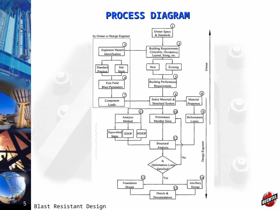
PROCESS DIAGRAMPROCESS DIAGRAM

Blast Resistant Design6
BASIC INFORMATIONBASIC INFORMATION• Client Specification• Plot Plan and ELP• Architectural Drawings• System Vulnerability and Safety Requirements
DESIGN PROCESSDESIGN PROCESS• Step 1: Load Calculation• Step 2: Determination of Member Properties• Step 3: Model Representation• Step 4: Trial Member Section• Step 5: Dynamic Analysis• Step 6: Deformation Criteria Check• Step 7: Connection Design• Step 8: Foundation Design
Note: Damage level determined by Owners.
Blast Resistant Design7
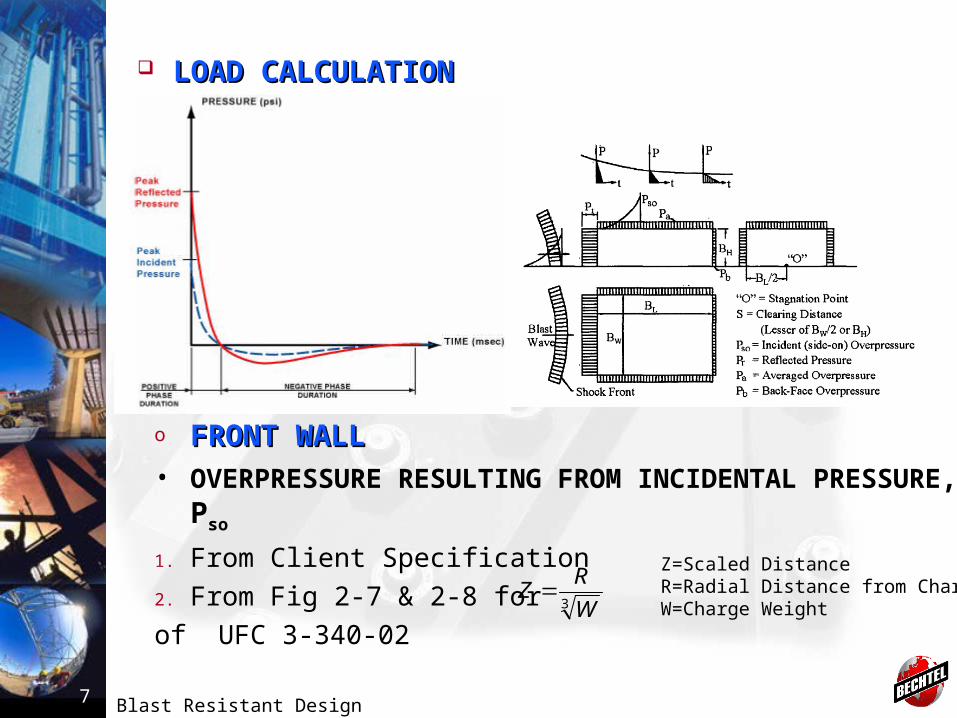
o FRONT WALLFRONT WALL• OVERPRESSURE RESULTING FROM INCIDENTAL
PRESSURE, Pso
1. From Client Specification
2. From Fig 2-7 & 2-8 for
of UFC 3-340-023 W
RZ
Z=Scaled DistanceR=Radial Distance from ChargeW=Charge Weight
LOAD CALCULATIONLOAD CALCULATION
Blast Resistant Design8
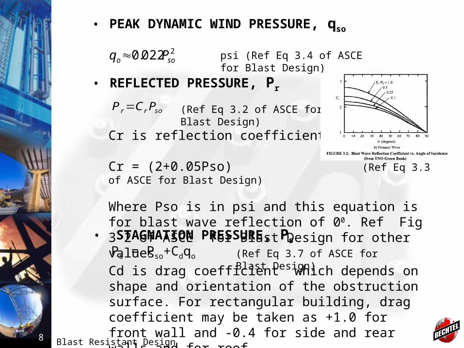
• PEAK DYNAMIC WIND PRESSURE, qso
2022.0 soo Pq psi (Ref Eq 3.4 of ASCE for Blast Design)
• REFLECTED PRESSURE, Pr
sorr PCP (Ref Eq 3.2 of ASCE for Blast Design)
Cr is reflection coefficient
Cr = (2+0.05Pso) (Ref Eq 3.3 of ASCE for Blast Design)
Where Pso is in psi and this equation is for blast wave reflection of 00. Ref Fig 3-2 of ASCE for Blast Design for other values
• STAGNATION PRESSURE, Ps
Ps = Pso+Cdqo (Ref Eq 3.7 of ASCE for Blast Design)
Cd is drag coefficient which depends on shape and orientation of the obstruction surface. For rectangular building, drag coefficient may be taken as +1.0 for front wall and -0.4 for side and rear walls and for roof
Blast Resistant Design9
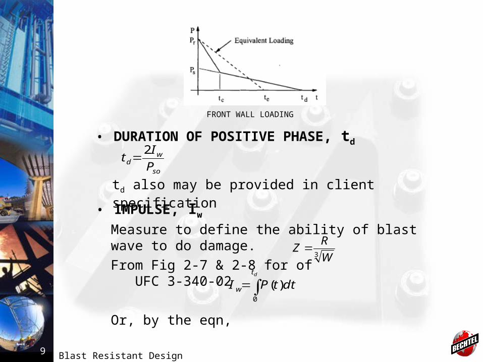
FRONT WALL LOADING
• DURATION OF POSITIVE PHASE, td
td also may be provided in client specificationso
wd P
It
2
• IMPULSE, Iw
Measure to define the ability of blast wave to do damage.From Fig 2-7 & 2-8 for of UFC 3-340-02
Or, by the eqn,
3 W
RZ
dt
w dttPI0
)(
Blast Resistant Design10
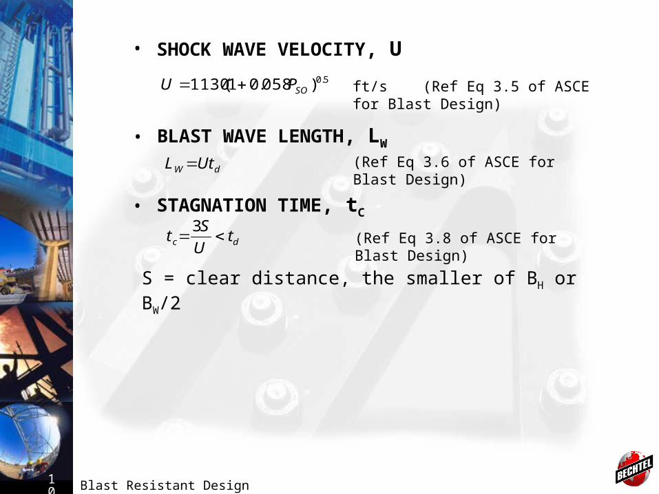
• SHOCK WAVE VELOCITY, U
ft/s (Ref Eq 3.5 of ASCE for Blast Design)5.0)058.01(1130 SOPU
• BLAST WAVE LENGTH, LW
(Ref Eq 3.6 of ASCE for Blast Design)dW UtL
• STAGNATION TIME, tC
(Ref Eq 3.8 of ASCE for Blast Design)dc tU
St
3
S = clear distance, the smaller of BH or BW/2
Blast Resistant Design11
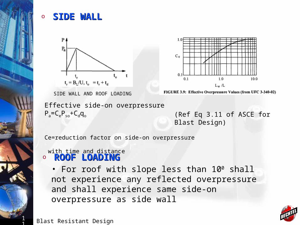
o ROOF LOADINGROOF LOADING• For roof with slope less than 100 shall not experience any reflected overpressure and shall experience same side-on overpressure as side wall
(Ref Eq 3.11 of ASCE for Blast Design)
o SIDE WALLSIDE WALL
SIDE WALL AND ROOF LOADING
Effective side-on overpressurePa=CePso+Cdqo
Ce=reduction factor on side-on overpressure
with time and distance
Blast Resistant Design12
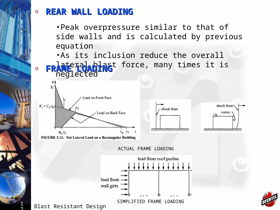
o REAR WALL LOADINGREAR WALL LOADING
•Peak overpressure similar to that of side walls and is calculated by previous equation•As its inclusion reduce the overall lateral blast force, many times it is neglected
o FRAME LOADINGFRAME LOADING
ACTUAL FRAME LOADING
SIMPLIFIED FRAME LOADING
Blast Resistant Design13
o SUCTION DUE TO NEGATIVE PHASE PULSESUCTION DUE TO NEGATIVE PHASE PULSE• Peak value of negative phase pressures are generally small compared with peak positive overpressure, however durations is longer.
DETERMINATION OF MEMBER PROPERTIESDETERMINATION OF MEMBER PROPERTIES
Dynamic yield strengthFdy=(Fy)(SIF) (DIF)
o STRENGTH INCRESE FACTOR, SIFSTRENGTH INCRESE FACTOR, SIF
• Actual yield strength is higher than the values mentioned in codes and specification. SIF used to account this condition.
• Refer Appendix 5.A of ASCE for Blast Design for SIF values.
o LOAD COMBINATIONLOAD COMBINATIONU(T) = D+aL+B(t)U(t) = total applied time dependant loadD=static dead loadL=live load, a=reduction factor to live loadB(t)=time dependant blast load
Blast Resistant Design14
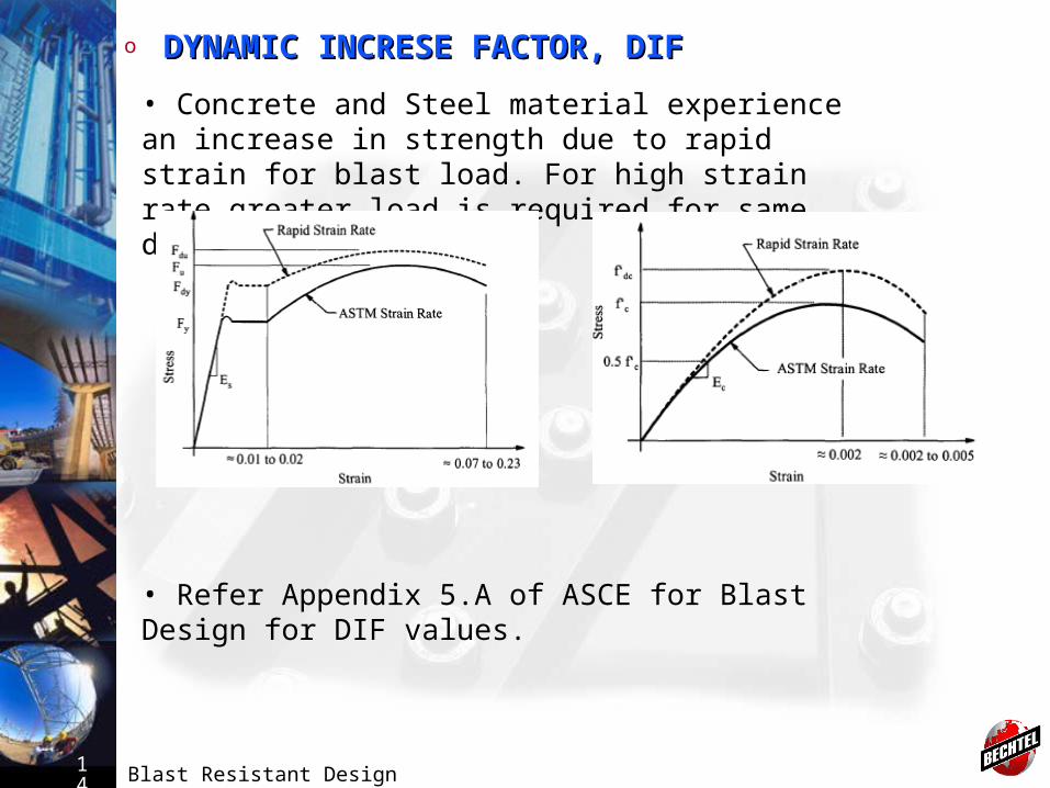
o DYNAMIC INCRESE FACTOR, DIFDYNAMIC INCRESE FACTOR, DIF
• Concrete and Steel material experience an increase in strength due to rapid strain for blast load. For high strain rate greater load is required for same deformation.
• Refer Appendix 5.A of ASCE for Blast Design for DIF values.

Blast Resistant Design15
MODEL REPRESENTATIONMODEL REPRESENTATION• Structural member representation• One-way or two-way action• Loading distribution for each member• Connection philosophy
TRIAL MEMBER SELECTIONTRIAL MEMBER SELECTION• Dynamic analysis requires trial member sizes• Nonlinear response properties are calculated from the trial sections
DYNAMIC ANALYSISDYNAMIC ANALYSIS• Equivalent Static Method• Single Degree of Freedom Systems (SDOF)• Multi-Degree of Freedom System (MDOF)
Blast Resistant Design16
o EQUIVALENT STATIC METHODEQUIVALENT STATIC METHOD
• Approximate load, called “equivalent wind” is applied to simulate dynamic response. • This is not recommended in ASCE for Blast Loading (Cl: 6.3) and can only be used when structure is far away from blast source and blast loading acts like wind gust
o SINGLE DEGREE OF FREEDOM SYSEMS (SDOF)SINGLE DEGREE OF FREEDOM SYSEMS (SDOF)
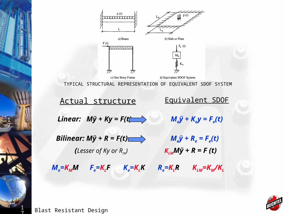
• For common types of structures like single story frames, cantilever wall, box like building. • All structures posses more than one degree of freedom which can be represented as series of SDOF.• Approximation of equivalent SDOF for structural components requires deflected shape and strain energy equivalence between actual structure and SDOF approximation.
Blast Resistant Design17
17 Linear: Mÿ + Ky = F(t) Meÿ + Key = Fe(t)
Bilinear: Mÿ + R = F(t) Meÿ + Re = Fe(t)
(Lesser of Ky or Rm) KLMMÿ + R = F (t)
Me=KMM Fe=KLF Ke=KLK Re=KLR KLM=KM/KL
Actual structure Equivalent SDOF
TYPICAL STRUCTURAL REPRESENTATION OF EQUIVALENT SDOF SYSTEM
Blast Resistant Design18
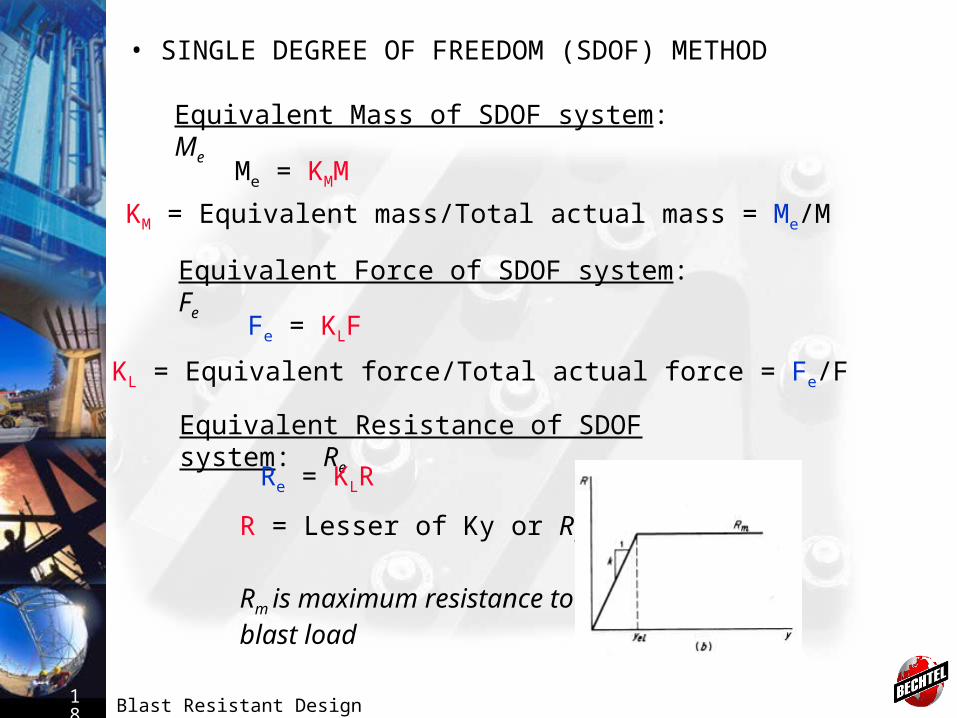
• SINGLE DEGREE OF FREEDOM (SDOF) METHOD
Equivalent Mass of SDOF system: Me
Me = KMM
KM = Equivalent mass/Total actual mass = Me/M
Equivalent Force of SDOF system: Fe
Fe = KLF
KL = Equivalent force/Total actual force = Fe/F
Equivalent Resistance of SDOF system: Re
Re = KLR
R = Lesser of Ky or Rm
Rm is maximum resistance to blast load

Blast Resistant Design19
Blast Resistant Design20
o MULTI-DEGREE OF FREEDOM SYSEMS (MDOF)MULTI-DEGREE OF FREEDOM SYSEMS (MDOF)
• Shall be used when structural configuration is complex or significant dynamic interaction between interconnected member can not be avoided.• Will require computer analysis.• Finite element analysis shall be performed.• Software associated with nonlinear analysis should be used (e.g., ANSYS)• Due to association of nonlinearity with plasticity, there is possibility of large displacement. Hence direct time integration (time-pressure / load diagram) method should be used.• Available commercial computer programs for dynamic nonlinear finite element analysis suitable for use in blast resistant design are LS-DYNA, ABAQUS, ADINA, ANSYS, MSC/NASTRAN and FLEX.
Blast Resistant Design21
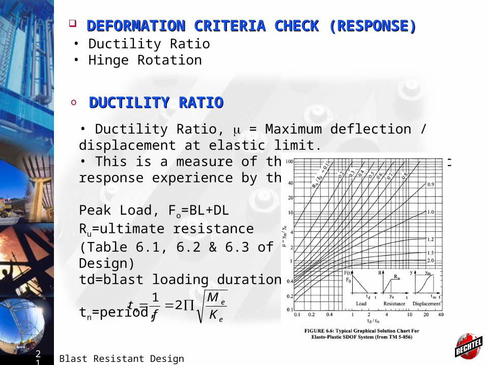
DEFORMATION CRITERIA CHECK (RESPONSE)DEFORMATION CRITERIA CHECK (RESPONSE)• Ductility Ratio• Hinge Rotation
o DUCTILITY RATIODUCTILITY RATIO
• Ductility Ratio, = Maximum deflection / displacement at elastic limit. • This is a measure of the degree of inelastic response experience by the member
Peak Load, Fo=BL+DLRu=ultimate resistance(Table 6.1, 6.2 & 6.3 of ASCE for Blast Design)td=blast loading duration
tn=period,
e
en K
M
ft 2
1

Blast Resistant Design22
o HINGE ROTATIONHINGE ROTATION
• It relates maximum deflection to span and indicates the degree of instability present in the critical areas of the member.
Refer Appendix 5.B of ASCE for Blast Design for allowable deformation limits
Ductility μ=ym/ye
Resistance – Deflection Curve
Blast Resistant Design23
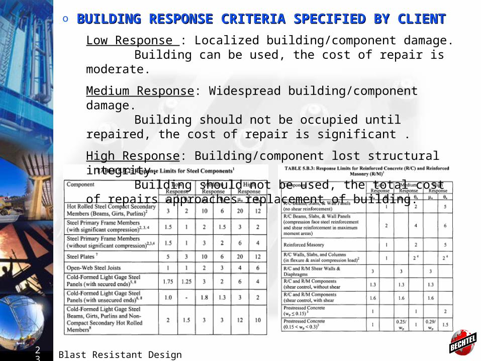
o BUILDING RESPONSE CRITERIA SPECIFIED BY CLIENTBUILDING RESPONSE CRITERIA SPECIFIED BY CLIENT
Low Response : Localized building/component damage.Building can be used, the cost of repair is moderate.
Medium Response: Widespread building/component damage.Building should not be occupied until repaired, the cost of repair is
significant .
High Response: Building/component lost structural integrity.Building should not be used, the total cost of repairs approaches
replacement of building.
Blast Resistant Design24
CONNECTION DESIGNCONNECTION DESIGN• Plastic hinge developed should be maintained.• For reinforce concrete design, splices and development lengths must be provided for the full yield capacities of reinforcement• For steel design, connections are designed for a capacity somewhat greater that that of its supported member.
FOUNDATION DESIGNFOUNDATION DESIGN• Should be more rigid than conventional structural foundation• Relative displacement between column and walls need to be minimized in order to maintain structural integrity. This is accomplished using grade beams to tie spread footings or pile cap or by using combined mat foundation.• Foundation can be analyzed by static analysis and dynamic analysis
Blast Resistant Design25
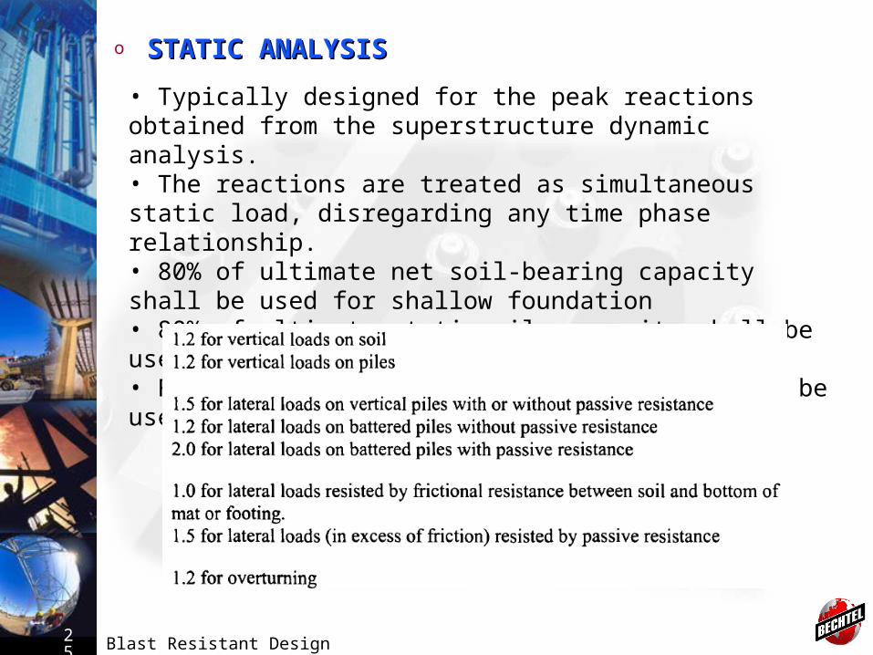
o STATIC ANALYSISSTATIC ANALYSIS
• Typically designed for the peak reactions obtained from the superstructure dynamic analysis.• The reactions are treated as simultaneous static load, disregarding any time phase relationship.• 80% of ultimate net soil-bearing capacity shall be used for shallow foundation• 80% of ultimate static pile capacity shall be used for deep foundation• Followings are factor of safety which shall be used for static analysis as per ASCE
Blast Resistant Design26
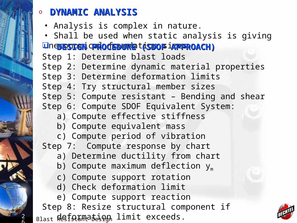
o DYNAMIC ANALYSISDYNAMIC ANALYSIS
• Analysis is complex in nature.• Shall be used when static analysis is giving uneconomical foundation sizes. DESIGN PROCEDURE (SDOF APPROACH)DESIGN PROCEDURE (SDOF APPROACH)Step 1: Determine blast loadsStep 2: Determine dynamic material propertiesStep 3: Determine deformation limitsStep 4: Try structural member sizesStep 5: Compute resistant – Bending and shearStep 6: Compute SDOF Equivalent System:
a) Compute effective stiffnessb) Compute equivalent massc) Compute period of vibration
Step 7: Compute response by charta) Determine ductility from chartb) Compute maximum deflection ym
c) Compute support rotationd) Check deformation limite) Compute support reaction
Step 8: Resize structural component if deformation limit exceeds.
Blast Resistant Design27
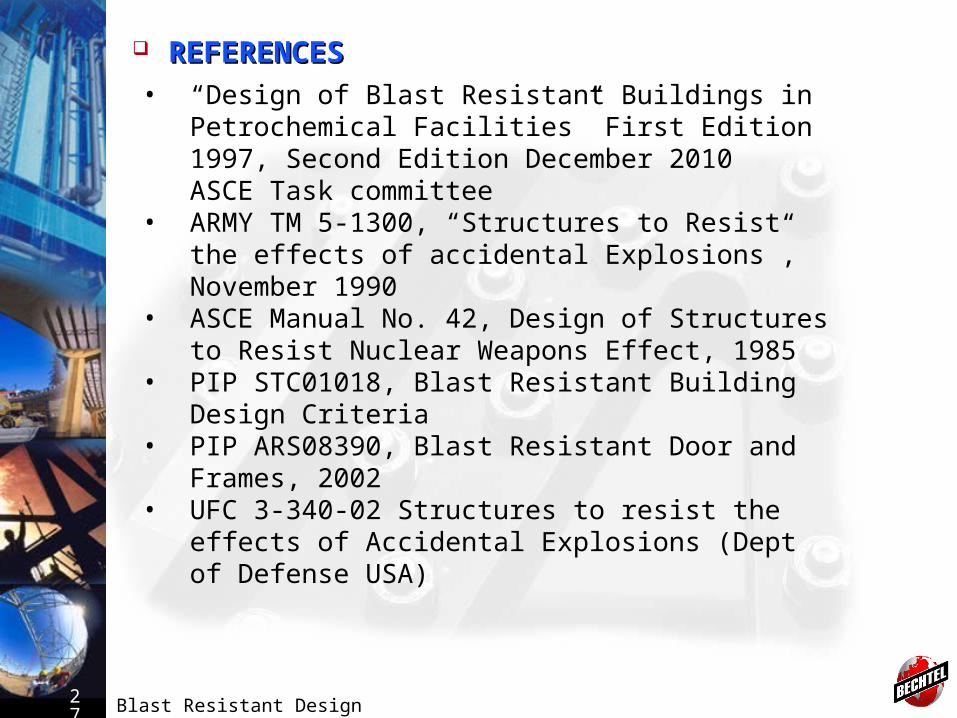
REFERENCESREFERENCES• “Design of Blast Resistant Buildings in Petrochemical
Facilities” First Edition 1997, Second Edition December 2010 ASCE Task committee
• ARMY TM 5-1300, “Structures to Resist the effects of accidental Explosions”, November 1990
• ASCE Manual No. 42, Design of Structures to Resist Nuclear Weapons Effect, 1985
• PIP STC01018, Blast Resistant Building Design Criteria
• PIP ARS08390, Blast Resistant Door and Frames, 2002
• UFC 3-340-02 Structures to resist the effects of Accidental Explosions (Dept of Defense USA)
Blast Resistant Design28
THANKS!
QUESTIONS ?


![[THESIS PROPOSAL] - Penn State College of Engineering. Design the blast resistant glass façade using “Blast‐Resistant Glazing Design” by H. Scott Norville & Edward Conrath in](https://img.dokumen.tips/doc/110x75/5ad8019b7f8b9a9d5c8cc819/thesis-proposal-penn-state-college-of-engineering-design-the-blast-resistant.jpg)