Embed Size (px)
Citation preview

Blades and Balancing
The easiest way to make blades for your autogyro is to purchase 3” x ¼” x 24” airfoil shaped balsa from SIG mfg. They are somewhat close to the desired shape. If you like, you can use aileron stock or even plain ¼” stock but with more sanding involved of course. Some even like to substitute hardwood leading edge in
place of the .093 music wire.

Now…. there is some basic knowledge that you need to make this happen.
You need to understand how the blades work. As you may know already, the autogyro blades spin from the wind hitting on the bottom side thus pushing the leading edge forward. This is achieved by
an upswept back area under the blade's trailing edge. So the wind gets the blades spinning, but there is something else that needs to happen to achieve flight. You
need a Clark Y profile on top of the blades to create lift once the blades get at a certain rpm. See my illustration on the next page. Also remember my blades spin counter clockwise.
Try to find blades that are close to the same wieght.

As you can see from my drawing, I cut 3/4” off the trailing edge of the 3” wide blade. I did this for an illustration. You will cut off ¾” so you will have extra to work with when it comes time to sand the
profiles in. Cutting the original trailing edge off the 3” SIG blades allows you to sand that upswepped bevel edge in and still be able to taper the top surface of the clark Y profile. That is the great thing about cutting off the trailing edge. It is thick, perfect thickness for sanding the bevel on the bottom
and Clark Y profile on the top of the blade. The Clark Y profile is simply a flat bottom wing that you have seen in so many RC plane wings and full size planes. Provides great lift. Perfect for the autogyro!

Cut off ¾ “ from the trailing edge. Make sure that is the correct edge has been chosen!
Once the trailing edge has been cut, measure from the new trailing edge, 1/2” toward the leading edge and mark that all the way down the balsa. You will sand the bevel in later.

Now cut your base and tip as per the plans.
Next thing to do is to cut out your 1/32” ply sheets for the base and glue them on. Epoxy works best.

Once they are dry, it will be time to start sanding the Clark Y profile in. You will see that a good 3/4” from the trailing edge will need to be tapered down. Leave 1/8” from the flat bottom. This will
give you the amount needed to sand in the bevel for the upswept trailing edge.
On the plans, I have a diagram of the cross section of the blades. You can trace over that on to a piece of thin plywood and use this as a gage for sanding in the negative pitch and also the Clark Y profile. This may aid you in keeping a consistent angle and Clark Y profile. I have made a lot of
blades in the past. I can feel if is good or not. You will get better with every set that you build. Just remember, this may be all new to you. Take your time.

The photo below shows what the trailing edge bevel and the Clark Y profile should look like. I added some color to show the defined lines and to what shapes you need to sand.
Let’s see! You have cut, glued, sanded and are almost finished! Time to strengthen your blades. You will need 3/32” or .093 diameter music wire and this will glued onto the leading edge. This will give
you the strength you need to keep your blades from breaking. As you will see from the plan, you need to bend a 90 degree bend x ¼” and make sure all three are the same length. That will aid in
your balancing if you keep all wires exactly the same length. I use flexible glue like Goo or Shoe Goo. It gives a strong bond and it flexes thus not cracking like CA or Epoxy.

Next step is to apply Balsa Lock onto the entire blade. You need to water it down first, other wise when you cover….it will wrinkle bad. Water it down like to a cream viscosity.
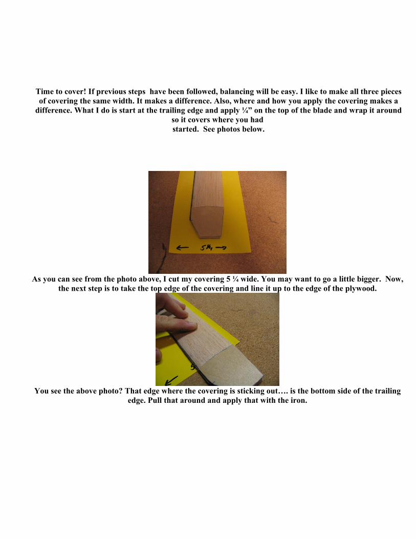
Time to cover! If previous steps have been followed, balancing will be easy. I like to make all three pieces of covering the same width. It makes a difference. Also, where and how you apply the covering makes a
difference. What I do is start at the trailing edge and apply ¼” on the top of the blade and wrap it around so it covers where you had started. See photos below.
As you can see from the photo above, I cut my covering 5 ¼ wide. You may want to go a little bigger. Now, the next step is to take the top edge of the covering and line it up to the edge of the plywood.
You see the above photo? That edge where the covering is sticking out…. is the bottom side of the trailing edge. Pull that around and apply that with the iron.

Now, pull the covering around to the top of the blade. You can even pin, tape or clamp the covering temporarily before applying heat. Take your time, this is not a race. Going slow will make for a
much better job. Pleat the end. Iron it flat on your building board all the way around the edge. Then just cut the excess with scissors. I use a heat gun on the edges to shrink the edges a little more.

The last part of the covering is the base of the blades (plywood portion). Just take a piece covering and wrap around the base. A small portion will overlap onto the already covered blade. Don’t let too much
overlap happen when pulling the covering around. If you are happy with it, start applying the heat. Cover the top and bottom first. Once that is done, pleat the sides flat and cut off the excess. Adhere the overlap
onto the already covered portion of the blades. Done!!!


The Balancing TrickNotice that we have NOT drilled the mounting hole on the blade? This is because you need the blade finished and covered to balance it. Balancing the lengthways and intersecting 23” from the tip of the blades to the lengthways CG will determine where the mounting hole will be. You really need to be patient in these next steps. Rushing thru this will make your gyro a real pain to fly. You want the
rotors to spin smoothly…. not choppy and unbalanced.
The aluminum angle is used to balance the blade. First step will be to find the static CG of the blades. Just simply lay the blades across the angle aluminum to find its center point. Then mark
each of the blades. Compare the marks. If they are within a 1/4” of each other....you should be good. The futher out whack they are with the centerline balance...the more difficult it will for the final
balance.

Balance the blade one at a time to find the cross center of gravity. Each time you balance a blade, mark the balancing point or CG. Once all three blades are balanced, check to see how off they are when the tips are in line. They should be within ¼” of each other. If not…we will balance them out
using weight on the tips. More on the tip weights later.
Next is the length ways balancing. This will find the center line to follow for the mounting hole. I like to stand on one side of the blade, (leading edge) as I find the balancing point by placing the
blade length ways on the angle edge.
I line up the leading edge to the base of the aluminum angle by eye as I am looking down on it….this is to keep the distance of balance to the edge of the blade square. You will see if it is square or not by
looking at the edge. The distance from leading edge to the balance points must even out.

Once the blade is balanced…..keep that spot! Press down on the blade so that it dents the wood a little so you can see it. Turn the blade over and draw a line length ways down the blade on the
indentations made from the angle edge.

From the edge of the round tip of the blade, measure 23”, which will intersect the balance line you had drawn before! This is where you will drill your 3/16 diameter mounting hole. Drill all the holes
now!
This is and old photo...the correct measurement is 23” from tip as the blade length is NOW 24”.
You are almost done! Now this next part is simple if the blades a balance well. If they are off…then we will have to add weights to the tips. Mount the blades using 10-32 screws….I like lock nuts. I
actually use lock wing nuts…easier to take on and off.

Once the blades are mounted, make sure that they can move with force. You need to adjust the blades square to each other to find perfect balance.
See the photo above? The top blade is square to the bottom side of the triangle. Adjust each blade just like that. Turn the rotor and adjust each blade, use a carpenter’s square if you like.
15

Mount your gear box onto a piece of wood that you can hold secure in a vise. Turn the blades so that they rotate vertically or the rotor axle is on a horizontal axis. Now you can find out which blade is
heaviest by letting go of the blades and the heavy blade will turn and find the bottom. You can simply add Duct tape to the other two blade tips to get the perfect balance.
Good luck guys.........


![BLADES [PPT]](https://img.dokumen.tips/doc/110x75/55cf9bc6550346d033a75508/blades-ppt.jpg)