Embed Size (px)
Citation preview

IFAC – Cigré Symposium onPower plants & power systems control
Brussels, April 26-29, 2000
Session onControl concepts for conventional and non-conventional power plants
Black-startup simulation of a repowered thermoelectric unit
A. Borghetti * G. Migliavacca ^ C.A. Nucci * S. Spelta ^
* Department of Electrical Engineering, University of Bologna, Italy
^ CESI S.p.A. (ENEL Group) Milan, Italy
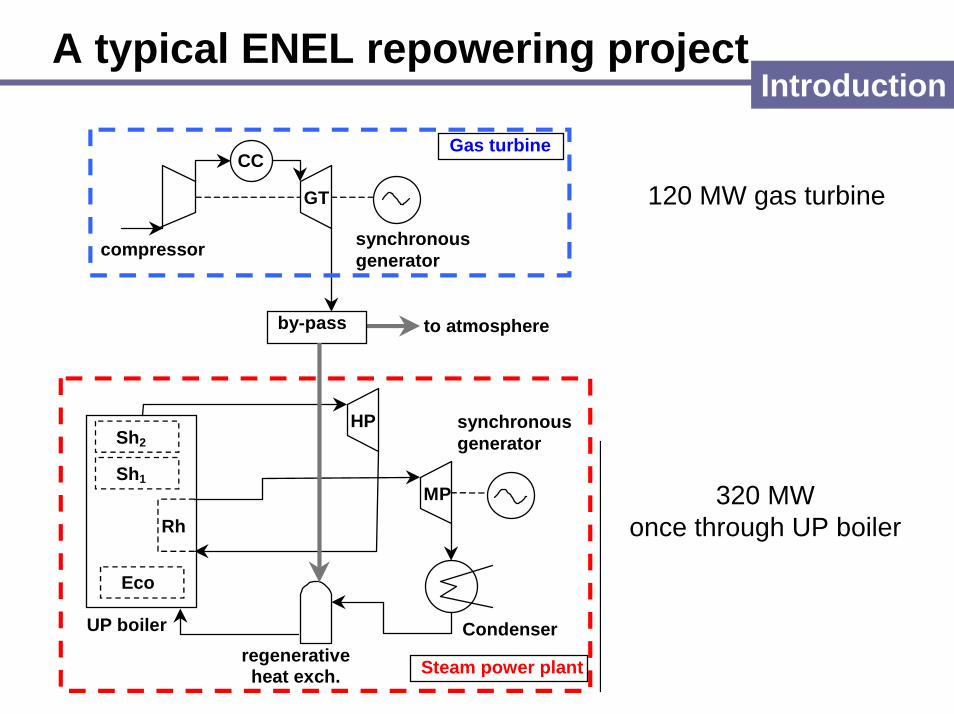
A typical ENEL repowering projectIntroduction
to atmosphereby-pass
Gas turbine
Steam power plant
compressor
GT
CC
synchronousgenerator
HP
MP
CondenserUP boiler
Rh
Sh1
Eco
regenerativeheat exch.
Sh2synchronousgenerator
120 MW gas turbine
320 MWonce through UP boiler

The problem to be studied
• Possibility to use a local repowering TG to perform a black start operation
on a UP-steam unit without feeding auxiliaries from the network. This could:
1. Spare precious time if load rejection on SPP fails
2. Avoid SPP auxiliaries feeding from network, complex operation involving
personnel on large geographical areas.
3. Allows to the group TG/SPP to feed at last other power stations, helping
to restore the network as fast as possible

The simulatorThe simulation environment
CESI has developed a real time simulation environment, named ALTERLEGO.
Its core consists of:• an efficient and reliable implicit solver of large sets of algebraic-differential
equations, • CAD-like user-friendly tools for building and managing models • a large library of mathematical models in the field of energy production processes.
A run-time executive enables to run together the various parts and the MMI.
ALTERLEGO man machine interface

Simulator structureThe simulator
Steam turbine
UP boiler with start-up circuit
Steam section control system
GTsynchronous
generator
Gasturbine
SPP load demandGT load demand
SPPsynchronous
generator
Electrical auxiliaries system and
external network
SPP
Load scheduler

• The temperature control is not represented and it is approximated by reducing the maximum fuel limit.
• The fuel valve positioner has two different actuation speed.
• Valve position 22% balance between gas turbine and compressor power
GT load
programmer
1
2
11+sT
sT1+sT
KsT1
1/droop
1+sT1
1+sT1
1+sT1
1sT
1
+
+
+
+
+
-
-
-
Frequency local integrator
Speedgovernor
GT loaddemand
Max acc.
P
cdfG
l l1
d1
d
d
f1
mech
Acceleration sensitive governor
ff n
0.1 0.3
1
d
Fuel valvepositioner
Fuel system Turbine
Compressordischarge
0,25 0,22 1
1
Gas turbine and its control
GT
Speed governor
FLI
The simulator
TG = 0.05 s speed governor time constantTVAL = 15 s valve time constant (opening)Tf = 0.1 s fuel system time constantTcd = 0.2 s compressor time constantKd = 10Td = 0.1 s accel. control transfer function ceff.Td1 = 1 sTl = 10 s FLI transfer function coeff.Tl1 = 4 s

GTmodelvalidation
The simulator
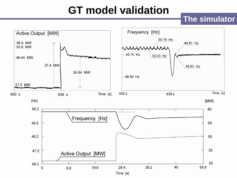
GT model validationThe simulator

• Thermal balance equations are not represented: loadconnections generate ∆Tmax=5-10 C
• Feedwater flow rate proportional to fuel flow rate at each load
• Steam production proportional to feedwater flow rate; time constant greater at diminishing loads
• Neglected F.T. drainings (but oil was increased byprogram at low load)
• Mass accumulation has been considered in: SH1, FT, SH2
UP Boiler: main assumptionsThe simulator

UP BoilerThe simulator
HP steam valve
From feedwater system
FLASH TANK
To deaerator
Boiler
V207
SH1
V205
V200 SH2
V240
Condenser
V270
HPRH
MP/BP

UP Boiler
1+sT1
sT
1sT
1sT
1+s1
1+0.5s1
k
k
k
k
205 noreturnvalve
k
boiler superheater 1
superheater 2
270 valve position
240 valve position
1
207 valveposition
Main steampressure
Fuel(steam
equivalent) b sh1
flash -tankpressure
200 valve steamflow rate
HP steam flowrate
SPP loaddemand
+ +
- -
-
+
+
++
-
+
- -
+
+
+
-
-+
ft
sh2
270
240
207
1+sTs
flash-tank
Relief valve
Relief valve
Steam flow rate toflash tank
1
195.5 204
1
182 190.4
Qft
Qsh1
x
sh2 presssurelosses
dd
sh1 outputpressure
flash into theboiler
Qsh2
Tb boiler time constantTsh1 = 7,5 s superheater 1 time constantTsh2 = 2,8 s superheater 2 time constantTft = 3 s flash tank time constant
Start-up circuit
SH2The simulator
SH1
boiler

Steam turbine and electrohydraulic controlThe simulator
ff n
1
21-y
11+sT
11-ysT
1sTΠ
+ +
+
+ +
+-Π+
--
-CH
HP steamchest
270 valve flowflow
RH
reheater
COFlp
HP control valvepositioner
intercept valvepositioner
y
crossover
Fhp
Impulse stagepressure regulator
Main steampressure
mechanicallosses function
Pmech
EHC loadreference
-
Tpr = 0,1 s pressure reg. time const.Tcv = 0,8 s control valve time const.TCH = 0,15 s HP chest time const.TRH = 11 s RH time const.TCO = 0,4 s crossover time const.y constant (prh,nom./pch,nom)Fhp = 0,4 fraction of total power generatedFlp = 0,6 by HP and LP sections
Qlp
Qhp
pCH
pRH
40%
60%
RH
Intercept
Admission
React. stages
Steam chest

Start-up control mode
fuel adjustment
SPP loaddemand
fuel programme
Fuel(steam equivalent)
+
-
+
+
+ + +
+-
1/droop
synchronisationadjustment
active power output
EHC loadreference
bias
0.1(1+1/10s)
80 MW
2.36
kg/s
kg/s
2.36
8.06
110 MW
-∆f
Control system

SPP model validation
The simulator

SPP smaller time contantbetween θamm and power
Great “inertia” betweenfuel and steam production
TG: greater time constantbetween fuel and power
The power is immediatelyavailable
Additional control system during
restoration Using TG to take load rapidly and bring to zero the frequencyerror (FLI)
When frequency and boiler pressure are correct, unload TG infavor of SPP so that TG preserves enough margin for subsequentload connections
Control system

Additional control system during
restoration
GTSPP
Control system

Auxiliaries’ electrical systemThe simulator

Models of the auxiliaries
4
4.5
5
5.5
6
6.5
0 10 20 30 40 50 60 70 80 90s
Bus
vol
tage
in
kV
4
4.5
5
5.5
6
6.5
0 10 20 30 40 50 60 70 80 90s
Bus
vol
tage
in
kV
The simulator
a)
b)
a) Start-up of 2 FW pumps
b) Residual voltage bus transfer
Motors: 3 order model
LV auxiliaries: static model
Time in s
0
1
2
3
4
5
6
7
2 4 6 8 10 12 14s]
Bus
vol
tage
kV
0
1
2
3
4
5
6
7
2 4 6 8 10 12 14s]
Bus
vol
tage
kV
Time in s

380/220 kV network near the power plant
Rossano Calabropower station
Laino
MontecorvinoTusciano
Rotonda
380 kV
380 kV
250 MVA 400 MVA
380 kV
220 kV
220 kV
100 MVA100 MVA
400 MVA
SPPGT
150 kVnetwork
121.2 km
126.5 km6.7 km
73.6 km 73.6 km
3 km
30MW
30MW
30MW
30MW
20MW
30MW
30MW
30MW
30MW
250 MVA
The simulator

150 kV network near the power plantThe simulator
RossanoCalabro
power station
5 MW
15 MW
15 MW
Scanzano
Nova Siri
Cirò
Crotone
15 MW
Acri
10 MW 30 MW 30 MW
Cosenza Cosenza Feroleto
5 MW
30 km 45 km 10 km 50 km
40 km
50 km
60 km
60 km

Ballast loadThe simulator
48 MW
13 MW
5 s
300 s
1,7 s

5.4
5.5
5.6
5.7
5.8
5.9
6
6.1
6.2
0 20 40 60 80 100 120 140 160 180 200 220Time s
Aux
iliar
ies’
bus
volta
ge k
V
with OLTCwithout OLTC
5.4
5.5
5.6
5.7
5.8
5.9
6
6.1
6.2
0 20 40 60 80 100 120 140 160 180 200 220Time s
Aux
iliar
ies’
bus
volta
ge k
V
with OLTCwithout OLTC
-45
-35
-25
-15
-5
5
15
25
35
45
55
1 21 41 61 81 101 121s
Mva
rTG reactive output with OLTC
SPP reactive output without OLTC
SPP reactive output with OLTC
TG reactive output without OLTC
-45
-35
-25
-15
-5
5
15
25
35
45
55
1 21 41 61 81 101 121s
Mva
rTG reactive output with OLTC
SPP reactive output without OLTC
SPP reactive output with OLTC
TG reactive output without OLTC
The simulator
OLTC model
Discrete
Inverse-time delay
a) OLTC of the start-up transformer(±16; 0.625%)
b) OLTC of Rotondatransformer(±8; 1.9%)
a)
b)
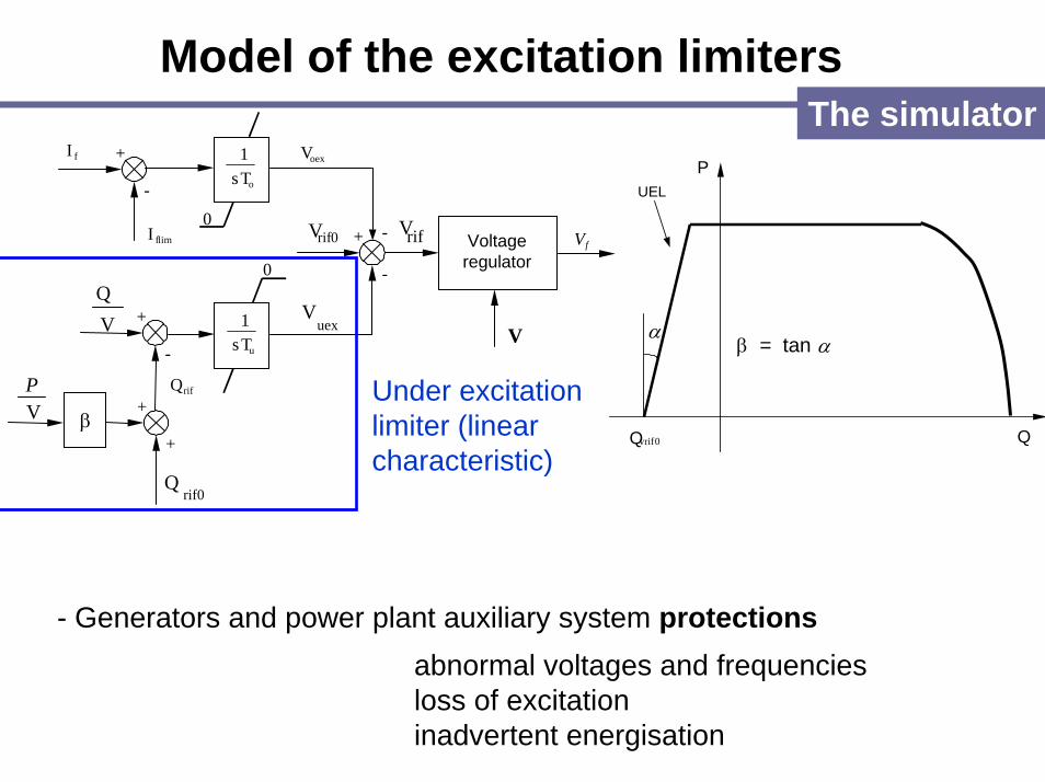
Model of the excitation limitersThe simulator
VP
0rifV Voltageregulator
oexV
+
-
oTs1+
-
uTs1+
-
limfI -
uexV
0
0
rifVfV
+
+
rif0Q
rifQ
β
VQ
fI
V
0vrifQ
P
α
UEL
β = tan α
Q
Under excitation limiter (linear characteristic)
- Generators and power plant auxiliary system protectionsabnormal voltages and frequenciesloss of excitationinadvertent energisation

Pick-up of a 30 MW loadsimulations
SPP alone

Pick-up of a 18 MW loadsimulations
SPP alone

0
10
20
30
40
50
60
70
0 100 200 300 400 500 600 700 800 900 1000 1100 1200
time in s
0
0.2
0.4
0.6
0.8
1
1.2
0
10
20
30
40
50
60
70
80
90
100
0 100 200 300 400 500 600 700 800 900 1000 1100 120046
47
48
49
50
51
FrequencyandSPP outputs
Pick-up of a 30 MW load(after other four loads) simulations
SPP alone
10 5
15
15
30
loads in MW
Control valve positionandFT pressure

simulations
Pick-up of a 30 MW load(after other four loads)
SPP alone
FrequencyandSPP outputs
Control valve positionandFT pressure

Pick-up of a 30 MW loadsimulations
SPP and GT synchronized

Power plant rampingsimulations
SPP and GT synchronized
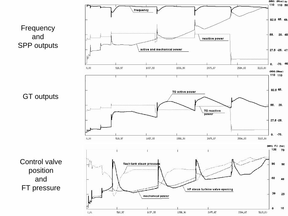
Frequencyand
SPP outputs
GT outputs
Control valve position
andFT pressure

Conclusions
The study carried out has shown that
• The GT section can effectively help the SPP section
under the start-up and ramping phases
• A load scheduler control system is crucial to coordinate
the load requests to the GT and the SPP generators
during the manoeuvre
• The repowered thermoelectric power unit can therefore
assume the role of "early-restoration plant“.