Embed Size (px)
Citation preview

BL20 – GATEWAY FORModbus RTU
Sense it! Connect it! Bus it! Solve it!

All brand and product names are trademarks or registered trade marks of the owner concerned.
Edition 05/2013
© Hans Turck GmbH, Muelheim an der Ruhr
All rights reserved, including those of the translation.
No part of this manual may be reproduced in any form (printed, photocopy, microfilm or any other process) or processed, duplicated or distributed by means of electronic systems without written permission of Hans Turck GmbH & Co. KG, Muelheim an der Ruhr.
Subject to alterations without notice

Table of Contents
1 About this manual
1.1 Documentation concept .................................................................................................................................1-2
1.2 Description of symbols used ..........................................................................................................................1-3
1.3 General ............................................................................................................................................................1-4
1.3.1 Prescribed use .........................................................................................................................................................................................1-41.3.2 Notes concerning planning/ installation of this product ........................................................................................................1-4
2 BL20-philosophy
2.1 The basic concept ............................................................................................................................................2-2
2.1.1 Flexibility ...................................................................................................................................................................................................2-22.1.2 Compactness ...........................................................................................................................................................................................2-22.1.3 Easy to handle .........................................................................................................................................................................................2-2
2.2 BL20 components ............................................................................................................................................2-3
2.2.1 Gateways ...................................................................................................................................................................................................2-32.2.2 Power distribution modules...............................................................................................................................................................2-42.2.3 Electronics modules (standard product line) ...............................................................................................................................2-52.2.4 ECO electronics modules.....................................................................................................................................................................2-62.2.5 Base modules...........................................................................................................................................................................................2-72.2.6 End plate....................................................................................................................................................................................................2-82.2.7 End bracket...............................................................................................................................................................................................2-82.2.8 Jumpers......................................................................................................................................................................................................2-92.2.9 Shield connection gateway ............................................................................................................................................................. 2-10
3 Technical features
3.1 Introduction .....................................................................................................................................................3-2
3.2 Function ...........................................................................................................................................................3-3
3.3 Technical data..................................................................................................................................................3-4
3.3.1 Block diagram..........................................................................................................................................................................................3-53.3.2 General technical data of a station .................................................................................................................................................3-53.3.3 Technical data for the push-in tension clamp terminals ........................................................................................................3-8
3.4 Connection options at the gateway...............................................................................................................3-9
3.4.1 Power supply ...........................................................................................................................................................................................3-93.4.2 Fieldbus connection........................................................................................................................................................................... 3-103.4.3 Service interface connection (mini USB female connector) ................................................................................................ 3-11
3.5 Configuration of the field bus parameters................................................................................................. 3-12
3.5.1 Standard mode (configuration via DIP-switches).................................................................................................................... 3-12
3.6 Synchronization of the station configuration............................................................................................ 3-16
3.6.1 DIP-switch CFG..................................................................................................................................................................................... 3-163.6.2 Extended mode (I/O-ASSISTANT 3 (FDT/DTM) ......................................................................................................................... 3-17
3.7 Status indicators/diagnostic messages gateway....................................................................................... 3-18
3.7.1 Diagnosis via LEDs .............................................................................................................................................................................. 3-18
D301295 0513 - BL20 - Modbus RTU i
4 Implementation of Modbus TCP
4.1 Common Modbus description ....................................................................................................................... 4-2
4.1.1 Protocol description ............................................................................................................................................................................. 4-34.1.2 Data model............................................................................................................................................................................................... 4-4
4.2 Implemented Modbus functions ................................................................................................................... 4-6
4.3 Modbus registers ............................................................................................................................................ 4-7
4.4 Structure of the packed in-/ output process data ...................................................................................... 4-12
4.4.1 Packed input process data ...............................................................................................................................................................4-134.4.2 Packed output process data ............................................................................................................................................................4-13
4.5 Data width of the I/O-modules in the modbus-register area .................................................................... 4-14
4.6 Register 0×100C: "Gateway status"............................................................................................................. 4-16
4.7 Register 0×113C und 0×113D: "Restore Modbus-Connection-Parameters" ........................................... 4-16
4.8 Register 0×113E und 0×113F: "Save Modbus-Connection-Parameters" ................................................. 4-17
4.9 The Service-Object........................................................................................................................................ 4-17
4.10 Bit areas: mapping of input-discrete- and coil-areas................................................................................. 4-20
4.11 Error behavior of outputs (watchdog) ........................................................................................................ 4-20
4.12 Parameters of the modules. ......................................................................................................................... 4-21
4.12.1 Digital input modules ........................................................................................................................................................................4-214.12.2 Analog input modules .......................................................................................................................................................................4-224.12.3 Analog output modules ....................................................................................................................................................................4-304.12.4 Technology modules..........................................................................................................................................................................4-35
4.13 Diagnostic messages of the modules.......................................................................................................... 4-45
4.13.1 Power distribution modules ............................................................................................................................................................4-454.13.2 Digital input modules ........................................................................................................................................................................4-464.13.3 Analog input modules .......................................................................................................................................................................4-464.13.4 Digital output modules .....................................................................................................................................................................4-494.13.5 Analog output modules ....................................................................................................................................................................4-514.13.6 Technology modules..........................................................................................................................................................................4-52
5 Application example: Modbus
5.1 Used hard-/ software ...................................................................................................................................... 5-2
5.1.1 Hardware .................................................................................................................................................................................................. 5-25.1.2 Software .................................................................................................................................................................................................... 5-2
5.2 Configuring the hardware.............................................................................................................................. 5-3
5.2.1 Connection of the BL20-gateway in the example ..................................................................................................................... 5-4
5.3 Operation with CoDeSys ................................................................................................................................ 5-5
5.3.1 Predefined feature sets........................................................................................................................................................................ 5-55.3.2 Creating a new project ........................................................................................................................................................................ 5-65.3.3 Defining the communication settings ........................................................................................................................................... 5-85.3.4 Adding the Modbus COM port ......................................................................................................................................................5-105.3.5 Adding the serial Modbus master .................................................................................................................................................5-125.3.6 Adding a Modbus-slave.....................................................................................................................................................................5-135.3.7 Programming (example program) ................................................................................................................................................5-16
D301295 0513 - BL20 - Modbus RTUii
5.3.8 CoDeSys: Global variables................................................................................................................................................................ 5-175.3.9 Modbus channels ................................................................................................................................................................................ 5-185.3.10 Building, login and start.................................................................................................................................................................... 5-305.3.11 Reading out the process data ......................................................................................................................................................... 5-315.3.12 Diagnosis evaluation.......................................................................................................................................................................... 5-32
6 Guidelines for station planning
6.1 Module arrangement ......................................................................................................................................6-2
6.1.1 Random module arrangement..........................................................................................................................................................6-26.1.2 Complete planning................................................................................................................................................................................6-36.1.3 Maximum system extension ..............................................................................................................................................................6-3
6.2 Power supply ...................................................................................................................................................6-6
6.2.1 Power supply to the gateway ............................................................................................................................................................6-66.2.2 Module bus refreshing .........................................................................................................................................................................6-66.2.3 Creating potential groups...................................................................................................................................................................6-66.2.4 C-rail (cross connection) ......................................................................................................................................................................6-76.2.5 Direct wiring of relay modules ..........................................................................................................................................................6-9
6.3 Protecting the service interface on the gateway ....................................................................................... 6-10
6.4 Plugging and pulling electronics modules................................................................................................. 6-10
6.5 Extending an existing station...................................................................................................................... 6-10
6.6 Firmware download ..................................................................................................................................... 6-11
7 Guidelines for electrical installation
7.1 General notes...................................................................................................................................................7-2
7.1.1 General .......................................................................................................................................................................................................7-27.1.2 Cable routing ...........................................................................................................................................................................................7-27.1.3 Lightning protection.............................................................................................................................................................................7-37.1.4 Transmission media...............................................................................................................................................................................7-3
7.2 Potential relationships....................................................................................................................................7-4
7.2.1 General .......................................................................................................................................................................................................7-4
7.3 Electromagnetic compatibility(EMC ..............................................................................................................7-5
7.3.1 Ensuring electromagnetic compatibility .......................................................................................................................................7-57.3.2 Grounding of inactive metal components....................................................................................................................................7-57.3.3 PE connection..........................................................................................................................................................................................7-57.3.4 Earth-free operation..............................................................................................................................................................................7-57.3.5 Mounting rails..........................................................................................................................................................................................7-6
7.4 Shielding of cables ..........................................................................................................................................7-7
7.5 Potential compensation..................................................................................................................................7-8
7.5.1 Switching inductive loads ...................................................................................................................................................................7-87.5.2 Protection against Electrostatic Discharge (ESD) .......................................................................................................................7-8
8 BL20-Approvals for Zone 2/ Division 2
D301295 0513 - BL20 - Modbus RTU iii

9 Appendix
9.1 Data image of the technology modules........................................................................................................ 9-2
9.1.1 1RS232/ 1RS485-module..................................................................................................................................................................... 9-29.1.2 SSI module................................................................................................................................................................................................ 9-69.1.3 SWIRE-module ......................................................................................................................................................................................9-139.1.4 Encoder/PWM-module: BL20-E-2CNT-2PWM............................................................................................................................9-159.1.5 RFID-module: BL20-2RFID-S.............................................................................................................................................................9-15
9.2 Ident codes the BL20-modules.................................................................................................................... 9-16
10 Index
D301295 0513 - BL20 - Modbus RTUiv

D3
1 About this manual
1.1 Documentation concept ............................................................................................................................... 2
1.2 Description of symbols used ....................................................................................................................... 3
1.3 General .......................................................................................................................................................... 4
1.3.1 Prescribed use .......................................................................................................................................................................................41.3.2 Notes concerning planning/ installation of this product ......................................................................................................4
01295 0513 - BL20 - Modbus RTU 1-1

About this manual
1.1 Documentation concept
This manual contains all information about the Modbus RTU-Gateway of the product line BL20 (BL20-E-GW-RS-MB-ET).
The following chapter contain a short BL20-description, a description of the used field bus system, exact information about function and structure of the field bus specific BL20-gateway as well as all bus specific information concerning the connection to automation devices, the maximum system extension etc.
The bus-independent I/O-modules of the BL20-system as well as all bus independent information as mounting, labeling etc. are described in a separate manual.
BL20 I/O-modules (TURCK-documentation no.: German D300716; English D300717)
In addition to that, the manual contains a short description of the I/O-ASSISTANT, the project planning and configuration software tool for TURCK I/O-systems-
D301295 0513 - BL20 - Modbus RTU1-2

Description of symbols used
1.2 Description of symbols used
WarningThis sign can be found next to all notes that indicate a source of hazards. This can refer to danger to personnel or damage to the system (hardware and software) and to the facility.
This sign means for the operator: work with extreme caution.
AttentionThis sign can be found next to all notes that indicate a potential hazard.
This can refer to possible danger to personnel and damages to the system (hardware and software) and to the facility.
NoteThis sign can be found next to all general notes that supply important information about one or more operating steps.
These specific notes are intended to make operation easier and avoid unnecessary work due to incorrect operation.
D301295 0513 - BL20 - Modbus RTU 1-3

About this manual
1.3 General
This manual includes all information necessary for the prescribed use of the BL20-E-GW-RS-MB/ET. It has been specially conceived for personnel with the necessary qualifications.
1.3.1 Prescribed use
Appropriate transport, storage, deployment and mounting as well as careful operating and thorough maintenance guarantee the trouble-free and safe operation of these devices.
1.3.2 Notes concerning planning/ installation of this product
AttentionPlease read this section carefully. Safety aspects cannot be left to chance when dealing with electrical equipment.
WarningThe devices described in this manual must be used only in applications prescribed in this manual or in the respective technical descriptions, and only with certified components and devices from third party manufacturers.
WarningAll respective safety measures and accident protection guidelines must be considered carefully and without exception.
D301295 0513 - BL20 - Modbus RTU1-4

D3
2 BL20-philosophy
2.1 The basic concept .......................................................................................................................................... 2
2.1.1 Flexibility .................................................................................................................................................................................................22.1.2 Compactness .........................................................................................................................................................................................22.1.3 Easy to handle .......................................................................................................................................................................................2
2.2 BL20 components.......................................................................................................................................... 3
2.2.1 Gateways .................................................................................................................................................................................................3– ECO-gateways ...................................................................................................................................................................................3– Gateways with integrated power supply ................................................................................................................................4– Gateways without integrated power supply .........................................................................................................................4
2.2.2 Power distribution modules.............................................................................................................................................................42.2.3 Electronics modules (standard product line) .............................................................................................................................52.2.4 ECO electronics modules...................................................................................................................................................................62.2.5 Base modules.........................................................................................................................................................................................72.2.6 End plate..................................................................................................................................................................................................82.2.7 End bracket.............................................................................................................................................................................................82.2.8 Jumpers ...................................................................................................................................................................................................92.2.9 Shield connection gateway........................................................................................................................................................... 10
01295 0513 - BL20 - Modbus RTU 2-1

BL20-philosophy
2.1 The basic concept
BL20 is a modular I/O system for use in industrial automation. It connects the sensors and actuators in the field with the higher-level master.
BL20 offers modules for practically all applications:
Digital input and output modules
Analog input and output modules
Technology modules (counters, RS232 interface...)
A complete BL20 station counts as one station on the bus and therefore occupies one fieldbus address in any given fieldbus structure.A BL20 station consists of a gateway, power distribution modules and I/O modules.
The connection to the relevant fieldbus is made via the bus-specific gateway, which is responsible for the communication between the BL20 station and the other fieldbus stations.
The communication within the BL20 station between the gateway and the individual BL20 modules is regulated via an internal module bus.
2.1.1 Flexibility
All BL20 stations can be planned to accommodate the exact number of channels to suit your needs, because the modules are available with different numbers of channels in block and slice design.
A BL20 station can contain modules in any combination, which means it is possible to adapt the system to practically all applications in automated industry.
2.1.2 Compactness
The slim design of the BL20 modules (standard gateway 50.4 mm / 1.98 inch, ECO gateway 34 mm/ 1.34 inch, standard slice 12.6 mm / 0.49 inch, ECO slice 13 mm / 0.51 inch and block 100.8 mm / 3.97 inch) and their low overall height favor the installation of this system in confined spaces.
2.1.3 Easy to handle
All BL20 modules of the standard line, with the exception of the gateway, consist of a base module and an electronics module.The gateway and the base modules are snapped onto a mounting rail. The electronics modules are plugged onto the appropriate base modules.
The base modules of the standard line are designed as terminal blocks. The wiring is secured by tension clamp or screw connection.
The electronics modules can be plugged or pulled when the station is being commissioned or for maintenance purposes, without having to disconnect the field wiring from the base modules.
The ECO electronics modules combine base module and electronics module in one housing. All BL20-ECO modules can be used with the standard products with tension clamp connection technology.
NoteThe gateway is the only fieldbus-dependent module on a BL20 station. All other BL20 modules are not dependent on the fieldbus used.
D301295 0513 - BL20 - Modbus RTU2-2

BL20 components
2.2 BL20 components
2.2.1 Gateways
The gateway connects the fieldbus to the I/O modules. It is responsible for handling the entire process data and generates diagnostic information for the higher-level master and the software tool PACTware with the respective TURCK-DTMs (I/O-ASSISTANT).
ECO-gateways
The BL20-ECO gateways enlarge the product portfolio of BL20. They offer an excellent cost/ performance ratio.
Further advantages of the gateways in the ECO-housing:
At the moment available for PROFIBUS-DP, DeviceNet™, CANopen, Modbus TCP, Modbus RTU/ASCII, EtherNet/IP™, EtherCAT® and PROFINET®.
Low required space: width 34 mm/ 1.34 inch minimal space requirements
Can be combined with all existing standard modules (with tension clamp connection technology) and ECO modules
Simple wiring with "Push-in" tension clamp terminals, via DeviceNet™-Open Style Connector or via Ethernet RJ45-connectors
Automatic bit rate detection for PROFIBUS-DP and DeviceNet™
Setting of fieldbus address and bus terminating resistor (PROFIBUS-DP, DeviceNet™, CANopen, Modbus RTU/ASCII) via DIP-switches
Service interface for commissioning with I/O-ASSISTANT 3 (FDT/DTM), without PLC.
Figure 2-1: Gateway BL20-E-GW-RS-MB/ET
D301295 0513 - BL20 - Modbus RTU 2-3
BL20-philosophy
Gateways with integrated power supply
All actual BL20-gateways provide an integrated power supply unit for supplying the gateway and the connected modules.
It is not necessary to supply the station using a special supply module with a separate voltage.
Gateways without integrated power supply
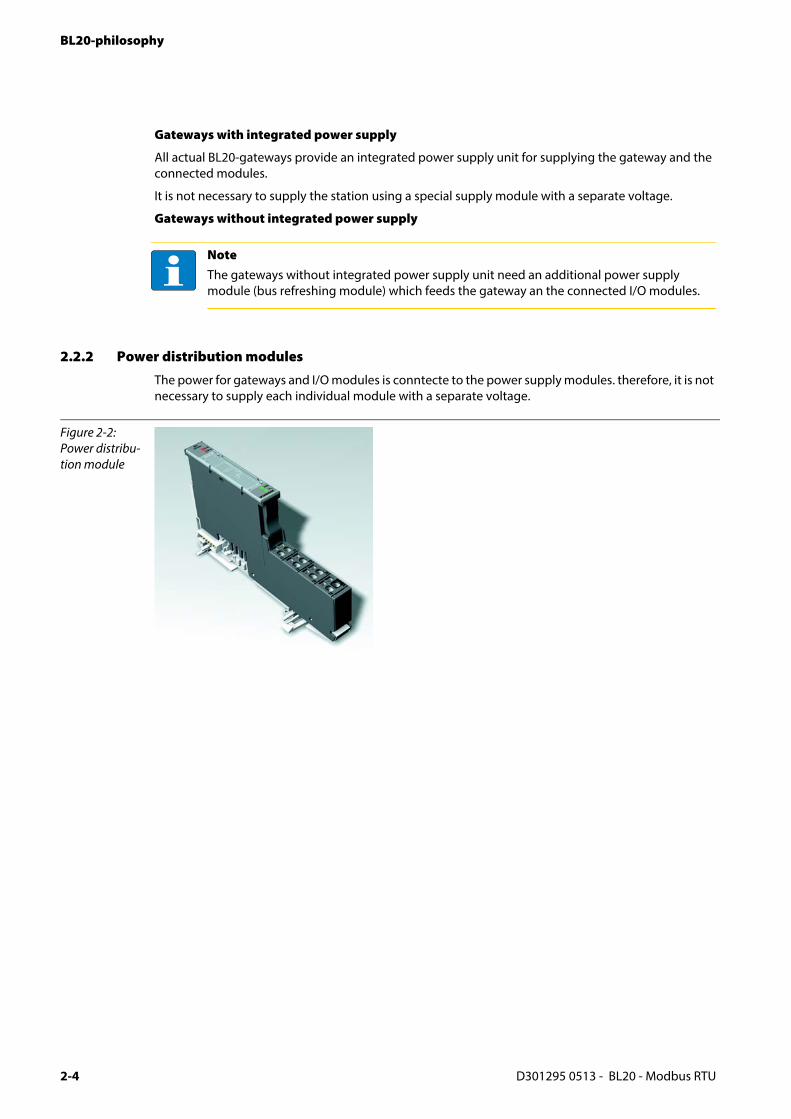
2.2.2 Power distribution modules
The power for gateways and I/O modules is conntecte to the power supply modules. therefore, it is not necessary to supply each individual module with a separate voltage.
NoteThe gateways without integrated power supply unit need an additional power supply module (bus refreshing module) which feeds the gateway an the connected I/O modules.
Figure 2-2: Power distribu-tion module
D301295 0513 - BL20 - Modbus RTU2-4

BL20 components
2.2.3 Electronics modules (standard product line)
The standard electronics modules contain the I/O-functions of the BL20 modules (power distribution modules, digital and analog input/output modules, and technology modules).
They are plugged onto the base modules and are not directly connected to the wiring
and can be plugged or pulled when the station is being commissioned or for maintenance purposes, without having to disconnect the field wiring from the base modules.
Figure 2-3: Electronics module in slice design (left) and in Block design (right)
D301295 0513 - BL20 - Modbus RTU 2-5

BL20-philosophy
2.2.4 ECO electronics modules
New ECONOMY modules with a high signal density and exceptionally low channel price expand the BL20 I/O bus terminal system.
Depending on type, up to 16 digital inputs and outputs can be connected on only 13 mm. This high connection density considerably reduces the mounting width required for typical applications.
All advantages at a glance:
Space saving thanks to 16 channels on 13 mm/ 0.51 inch width
Cost saving thanks to electronics with integrated connection level
High signal density
Tool-less connection via "push-in" spring-type terminal technology for simple and fast mounting
Flexibility in combining them with standard I/O-modules in tension clamp technology, the standard- and the ECO-gateways.
Simple assembly reduces error sources
Figure 2-4: ECO I/O-module
D301295 0513 - BL20 - Modbus RTU2-6

BL20 components
2.2.5 Base modules
The field wiring is connected to the base modules. These are constructed as terminals in block and slice designs and are available in the following variations with either tension clamp or screw connections: 2-/3-wire (2-channel), 4-wire (2-channel) and 4x2-/3-wire (4-channel).
Figure 2-5: Base module with tension clamp connec-tion
Figure 2-6: Base module with screw connection
Figure 2-7: Base module in block design
D301295 0513 - BL20 - Modbus RTU 2-7

BL20-philosophy
2.2.6 End plate
An end plate on the right-hand side physically completes the BL20 station. An end bracket mounted into the end plate ensures that the BL20 station remains secure on the mounting rail even when subjected to vibration.
2.2.7 End bracket
A second end bracket to the left of the gateway is necessary, as well as the one mounted into the end plate to secure the station.
Figure 2-8: End plate
Figure 2-9: End bracket
NoteThe end plate and two end brackets are delivered with the gateway.
D301295 0513 - BL20 - Modbus RTU2-8

BL20 components
2.2.8 Jumpers
Jumpers (QVRs) are used to bridge a connection level of a 4-wire base module. They can be used to connect potentials in relay modules (bridging the relay roots); thus considerably reducing the amount of wiring.
Labels: for labeling BL20 electronics modules.
Markers: for colored identification of connection levels of BL20 base modules.
Dekafix connector markers: for numbering the mounting slots on BL20 base modules.
Figure 2-10: Jumpers
Figure 2-11: Marking mate-rial
D301295 0513 - BL20 - Modbus RTU 2-9

BL20-philosophy
2.2.9 Shield connection gateway
If the gateway is wired directly to the fieldbus, it is possible to shield the connection using a special gateway-shielding connection attachment (BS3511/KLBUE4-31.5).
Figure 2-12: Shield connec-tion (gateway)
D301295 0513 - BL20 - Modbus RTU2-10
D3
3 Technical features
3.1 Introduction................................................................................................................................................... 2
3.2 Function ......................................................................................................................................................... 3
3.3 Technical data................................................................................................................................................ 4
3.3.1 Block diagram........................................................................................................................................................................................53.3.2 General technical data of a station ...............................................................................................................................................5
– Approvals and tests.........................................................................................................................................................................73.3.3 Technical data for the push-in tension clamp terminals ......................................................................................................8
3.4 Connection options at the gateway............................................................................................................. 9
3.4.1 Power supply .........................................................................................................................................................................................93.4.2 Fieldbus connection............................................................................................................................................................................93.4.3 Service interface connection (mini USB female connector) .............................................................................................. 10
3.5 Configuration of the field bus parameters ............................................................................................... 11
3.5.1 Standard mode (configuration via DIP-switches).................................................................................................................. 11– Address setting via DIP-switches (20 to 24) .......................................................................................................................... 12– Setting the bit rate........................................................................................................................................................................ 12– Activating the bus terminating resistor (RT) ........................................................................................................................ 14
3.6 Synchronization of the station configuration .......................................................................................... 15
3.6.1 DIP-switch CFG................................................................................................................................................................................... 153.6.2 Extended mode (I/O-ASSISTANT 3 (FDT/DTM)....................................................................................................................... 16
3.7 Status indicators/diagnostic messages gateway ..................................................................................... 17
3.7.1 Diagnosis via LEDs ............................................................................................................................................................................ 17
01295 0513 - BL20 - Modbus RTU 3-1

Technical features
3.1 Introduction
This chapter contains the technical description of the BL20-gateway for serial Modbus (RTU/ASCII).
The chapter contains: the technical data, the connection options, the description of address assignment etc..
D301295 0513 - BL20 - Modbus RTU3-2

Function
3.2 Function
BL20-gateways are used to connect BL20 I/O modules to the Modbus-network.
The gateway handles the entire process data exchange between the I/O-level and the fieldbus and generates diagnostic information for higher-level nodes and the software tool I/O-ASSISTANT.
D301295 0513 - BL20 - Modbus RTU 3-3

Technical features
3.3 Technical data
Figure 3-1: Front view
A LEDs for BL20 module bus
B service interfaceC DIP-switch for
node addressD DIP-switch for
bit rateE DIP-switch for
interface selec-tion
F DIP-switch for terminating resistor
G DIP-switch for the configura-tion acceptance
H LEDs for the serial communi-cation
I Field supplyJ System power
supplyK Fieldbus con-
nection
BA
D
C
F
H
I
E
K
G
J
GW
IOs
Rx
SERVICE
0 1
AD
DR
ES
S 20
21
22
23
24
RS232RT
CFG
Bps
OFF ON
Tx
Unl
ock
end-
brac
ket b
efor
e di
smou
ntin
g
Slid
e to
p co
ver
for
serv
ice
and
conf
igur
atio
n
UL
GNDL
USYS
GNDSYS
Tx / A
Rx / B
Tx / A
Rx / B
GND
SHLD
!BL20-E-GW-RS-MB/ET
12RS485
D301295 0513 - BL20 - Modbus RTU3-4

Technical data
3.3.1 Block diagram
3.3.2 General technical data of a station
Figure 3-2: Block diagram BL20-E-GW-RS-MB/ET
AttentionThe auxiliary power supply must comply with the stipulations of SELV (Safety Extra Low Voltage) according to IEC 364-4-41.
Table 3-1: General tech-nical data of a station
Supply voltage/auxiliary voltage
Usys (nominal value) provision for other modules
24 V DC
Isys (with maximul system extension, → see Maximum system extension (page 6-3)
approx. 600 mA
UL nominal value 24 V DC
ILmax (maximum current from field supply) 10 A
permissible range according to EN 61131-2 (18 to 30 V DC)
Residual ripple according to EN 61 131-2
Voltage anomalies according to EN 61 131-2
IMB (supply of module bus nodes) 400 mA
Connection technology push-in tension clamps, LSF from Weidmueller
Physical interfaces
Field bus serial Modbus (RS485/RS232)
Protocols ASCII and RTU
Transmission rate 9.6 to 115.2 kbps
CPU
5 V
24 V
Tx / A Usys
Service USB
UL
Module bus
RS232/RS485
Rx / B
D301295 0513 - BL20 - Modbus RTU 3-5
Technical features
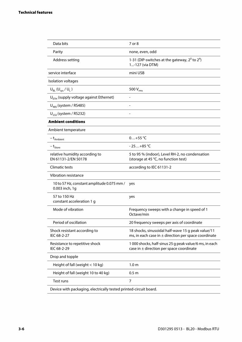
Data bits 7 or 8
Parity none, even, odd
Address setting 1-31 (DIP-switches at the gateway, 20 to 24)1...-127 (via DTM)
service interface mini USB
Isolation voltages
UBL (Usys / UL ) 500 Vrms
UETH (supply voltage against Ethernet) -
U485 (system / RS485) -
U232 (system / RS232) -
Ambient conditions
Ambient temperature
– tAmbient 0…+55 °C
– tStore - 25…+85 °C
relative humidity according to EN 61131-2/EN 50178
5 to 95 % (indoor), Level RH-2, no condensation (storage at 45 °C, no function test)
Climatic tests according to IEC 61131-2
Vibration resistance
10 to 57 Hz, constant amplitude 0.075 mm / 0.003 inch, 1g
yes
57 to 150 Hz constant acceleration 1 g
yes
Mode of vibration Frequency sweeps with a change in speed of 1 Octave/min
Period of oscillation 20 frequency sweeps per axis of coordinate
Shock resistant according to IEC 68-2-27
18 shocks, sinusoidal half-wave 15 g peak value/11 ms, in each case in ± direction per space coordinate
Resistance to repetitive shock IEC 68-2-29
1 000 shocks, half-sinus 25 g peak value/6 ms, in each case in ± direction per space coordinate
Drop and topple
Height of fall (weight < 10 kg) 1.0 m
Height of fall (weight 10 to 40 kg) 0.5 m
Test runs 7
Device with packaging, electrically tested printed-circuit board.
D301295 0513 - BL20 - Modbus RTU3-6

Technical data
Approvals and tests
Electromagnetic compatibility (EMC) according to EN 50 082-2 (Industry)
Static electricity according to EN 61 000-4-2
– Discharge through air (direct) 8 kV
– Relay discharge (indirect) 4 kV
Electromagnetic HF fields according to EN 61 000-4-3 and EN 50 204
10 V/m
A Using the device in residential areas can cause disturbances. In this case, addi-tional measures to suppress the disturbance are necessary.
Conducted interferences induced by HF fields according to EN 61 000-4-6
10 V
Fast transients (Burst) according to EN 61 000-4-4
Emitted interference according to EN 50 081-2 (industry)
according to EN 55 011 Class A A, group 1
Table 3-2: Approvals and tests for a BL20 station
Designation
Approvals
ULCSA
in preparation
Tests (EN 61131-2)
Cold DIN IEC 68-2-1, Temperature -25 °C / 185 °F, duration 96 h; device not in use
Dry heat DIN IEC 68-2-2, Temperature +85 °C / 185 °F, duration 96 h; device not in use
Damp heat, cyclic DIN IEC 68-2-30, temperature +55 °C / 131 °F, duration 2 cycles every 12 h; device in use
Operational life MTBF 120 000 h
Pollution severity according to IEC 664 (EN 61 131-2)
2
Protection class according to IEC 529 IP20
D301295 0513 - BL20 - Modbus RTU 3-7

Technical features
3.3.3 Technical data for the push-in tension clamp terminals
Table 3-3: Technical data Push-in tension clamp terminals
Designation
Protection class IP20
Insulation stripping length 8 mm + 1/ 0.32 inch + 0,039
Max. wire range 0.14 to 1.5 mm2 / 0.0002 to 0.0023 inch2/ 26 to 16 AWG
Crimpable wire
"e” solid core H 07V-U 0.14 to 1.5 mm2 / 0.0002 to 0.0023 inch2 / 26 to 16 AWG
"f” flexible core H 07V-K 0.5 to 1.5 mm2 / 0.0008 to 0.0023 inch2 / 25 to 16 AWG
"f” with ferrules according to DIN 46 228/1 (ferrules crimped gas-tight)
0.25 to 1.5 mm22 / 0.0004 to 0.0023 inch2 / 30 to 16 AWG
WarningThis device can cause radio disturbances in residential areas and in small industrial areas (residential, business and trading). In this case, the operator can be required to take appropriate measures to suppress the disturbance at his own cost.
D301295 0513 - BL20 - Modbus RTU3-8

Connection options at the gateway
3.4 Connection options at the gateway
The field bus as well as the power supply are connected to the gateway using push-in tension clamp terminals.
3.4.1 Power supply
The BL20-E-GW-GW-RS-MB/ET provides an integrated power supply unit and provides push-in tension clamps for:
field supply voltage (UL, GNDL)
and
system supply (USYS, GNDSYS)
Figure 3-3: Connection options at the gateway
Figure 3-4: Voltage supply connection
Unl
ock
end-
brac
ket b
efor
e di
smou
ntin
g
Slid
e to
p co
ver
for
serv
ice
and
conf
igur
atio
n
UL
GNDL
USYS
GNDSYS
Tx / A
Rx / B
Tx / A
Rx / B
GND
SHLD
!
=
=
+ –
+ –Field supply
System supply
D301295 0513 - BL20 - Modbus RTU 3-9

Technical features
3.4.2 Fieldbus connection
Table 3-4: Field bus connection - connection assignment
BL20-E-GW-RS-MB/ET
connection terminal
other adata end device
RS232-connection
GND GND
Rx / B RxD
Tx / A TxD
- RTS
- CTS
RS485-connection
Tx / A Rx/Tx+ (A)
Rx / B Rx/Tx- (B)120 120
D301295 0513 - BL20 - Modbus RTU3-10

Connection options at the gateway
3.4.3 Service interface connection (mini USB female connector)
The service interface is used to connect the gateway to the project planning and diagnostic software I/O-ASSISTANT (FDT/DTM).
The service interface is designed as a 5 pole mini-USB-connection.
In order to connect the gateway’s service-interface to the PC, a commercial cable with mini USB connector (commonly used for e.g. digital cameras) is necessary.
Figure 3-5: Mini-USD female connector at the gateway
GW
IOs
Rx
SERVICE
0 1
AD
DR
ES
S 20
21
22
23
24
RS232RT
CFG
Bps
OFF ON
Tx
BL20-E-GW-RS-MB/ET
12RS485
D301295 0513 - BL20 - Modbus RTU 3-11

Technical features
3.5 Configuration of the field bus parameters
The gateway can be configured in two different ways:
Standard mode (configuration via DIP-switches)In standard mode, some parameters can not be set ie DIP-switches and are thus fixed to these defaut settings:
– Data bits: 8
– Parity: even
– Stop bits: 1
– transmission: RTU
The other parameters can be set via DIP-switches.
Extended mode (I/O-ASSISTANT 3 (FDT/DTM) (state of delivery)
The extended mode allows the gateway's parameterization using the software tool I/O-ASSISTANT (FDT/DTM) and offers, besides the default parameters mentioned above, extended parameterization for the transmission rate and the address assignment.
3.5.1 Standard mode (configuration via DIP-switches)
The DIP-switches for the gateway-configuration are located under the upper label of the gateway.
They are used for:
assigning field bus address
setting certain bit rates
selecting the serial interface
activating the terminating resistor
storing the station configuration
NoteDetails concerning this issue are described in chapter 3.6.2.
D301295 0513 - BL20 - Modbus RTU3-12

Configuration of the field bus parameters
Address setting via DIP-switches (20 to 24)
Addresses from 1 bis 31 can be set.
Address 0 is reserved for the address assignment via I/O-ASSISTANT (FDT/DTM). The software tool provides an address assignment within the range of 1 to 247 (see also Extended mode (I/O-ASSISTANT 3 (FDT/DTM) (page 3-17)).
The gateway’s field bus address results from the addition of the valences (20 to 24) of the active DIP-switches (position = 1).
Example:
Bus address 27 = 0×1B = 11011
Figure 3-6: Address setting, address 27
NoteThe internal module bus does not require any addressing.
GW
IOs
SERVICE
Tx
0 1
AD
DR
ES
S
20
21
22
23
24
RT
CFG
off on
RS232 RS485
Bps
Tx
Rx
D301295 0513 - BL20 - Modbus RTU 3-13
Technical features
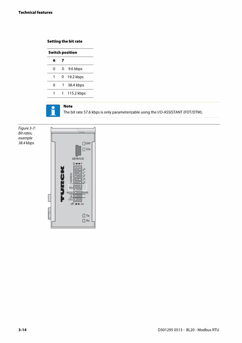
Setting the bit rate
Switch position
6 7
0 0 9.6 kbps
1 0 19.2 kbps
0 1 38.4 kbps
1 1 115.2 kbps
NoteThe bit rate 57.6 kbps is only parameterizable using the I/O-ASSISTANT (FDT/DTM).
Figure 3-7: Bit rates, example 38.4 kbps GW
IOs
SERVICE
Tx
0 1
AD
DR
ES
S
20
21
22
23
24
RT
CFG
off on
RS232 RS485
Bps
Tx
Rx
D301295 0513 - BL20 - Modbus RTU3-14

Configuration of the field bus parameters
Activating the bus terminating resistor (RT)
In RS485-operation mode, the termination of the filed bus line with terminating resistors is necessary.
If the device is used as first or last node in the RS485-line, the terminating resistor RT can be activated via the respective DIP-switch.
Figure 3-8: Bus terminating resistor RT
Bus termination resistor activated:
GW
IOs
SERVICE
Tx
0 1
AD
DR
ES
S
20
21
22
23
24
RT
CFG
off on
RS232 RS485
Bps
Tx
Rx
D301295 0513 - BL20 - Modbus RTU 3-15
Technical features
3.6 Synchronization of the station configuration
3.6.1 DIP-switch CFG
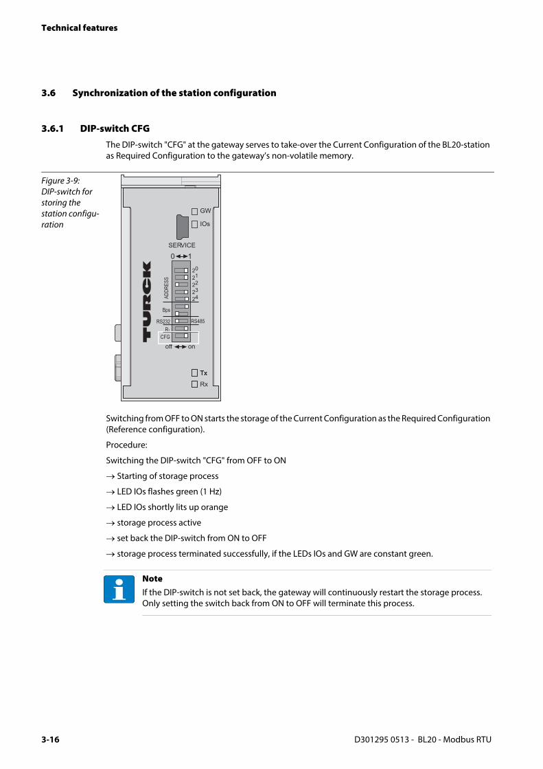
The DIP-switch "CFG" at the gateway serves to take-over the Current Configuration of the BL20-station as Required Configuration to the gateway’s non-volatile memory.
Switching from OFF to ON starts the storage of the Current Configuration as the Required Configuration (Reference configuration).
Procedure:
Switching the DIP-switch "CFG" from OFF to ON
→ Starting of storage process
→ LED IOs flashes green (1 Hz)
→ LED IOs shortly lits up orange
→ storage process active
→ set back the DIP-switch from ON to OFF
→ storage process terminated successfully, if the LEDs IOs and GW are constant green.
Figure 3-9: DIP-switch for storing the station configu-ration
NoteIf the DIP-switch is not set back, the gateway will continuously restart the storage process. Only setting the switch back from ON to OFF will terminate this process.
GW
IOs
SERVICE
Tx
0 1
AD
DR
ES
S
20
21
22
23
24
RT
CFG
off on
RS232 RS485
Bps
Tx
Rx
D301295 0513 - BL20 - Modbus RTU3-16

Synchronization of the station configuration
3.6.2 Extended mode (I/O-ASSISTANT 3 (FDT/DTM)
The parameterization via the software tool I/O-ASSISTANT (FDT/DTM) offers extended configuration posssibilities
extended address range
extended choice of bit rates
parameterization of parity, transmission mode, watchdog-times
NoteIn order to use parameterization in extended mode, the node's fieldbus address has to be set to "0". Only then, the parameters set via DTM are valid.
Figure 3-10: Extended configuration mode via software
D301295 0513 - BL20 - Modbus RTU 3-17

Technical features
3.7 Status indicators/diagnostic messages gateway
The gateway sends out the following diagnostic information:
undervoltage diagnosis for system and field supply
status of BL20-station
status of the internal communication via the module bus
status of the Ethernet communication
status of the gateway
Diagnostics messages are indicated in two different ways:
via the LEDs
via the configuration software (I/O-ASSISTANT) or the Modbus client
3.7.1 Diagnosis via LEDs
Every BL20-E-GW-RS-MB/ET displays the following statuses via LEDs:
2 LEDs for the module bus communication (module bus-LEDs): GW and IOs
2 LEDs for the serial communication: Rx and Tx
Table 3-5: LED-displays
LED Status Meaning Remedy
GW OFF No power supply of the CPU. Check the system power supply at the gateway.
green Firmware active, gateway ready -
green flashing,1 Hz
Firmware not active If LED "IOs" red, then firmware-download necessary
green flashing,4 Hz
Firmware active, gateway hardware error.
Replace the gateway.
red hardware failure Replace the gateway.
IOs OFF No power supply of the CPU. Check the system power supply at the gateway.
green The modules configured corre-spond to the modules in the station, communication running.
-
green flashing,1 Hz
Station is in the Force Mode of the I/O-ASSISTANT.
Deactivate the Force Mode of the I/O-ASSISTANT.
D301295 0513 - BL20 - Modbus RTU3-18

Status indicators/diagnostic messages gateway
IOs red Hardware failure, firmware not running.
– Replace the gateway, if necessary.
red flashing,1 Hz
Non adaptablechanges in the configuration of the module bus nodes.
– Compare the configured list of modules in your BL20-station to the current configuration.
– Check the physical station for defective or incorrectly plugged electronic modules.
red flashing, 4 Hz
No communicationvia the module bus.
– At least one module has to be plugged and has to be able to communicate with the gateway.
red / greenflashing, 1 Hz
The current and configured module list do not match but the data exchange proceeds as normal.
– Check the physical station for pulled or new but not planned modules.
Tx off idle
green Data are currently transferred.
Rx off idle
green Data are currently not received.
red Watchdog timeout concerning the watchdog, see also page 4-20
Table 3-5: LED-displays
LED Status Meaning Remedy
D301295 0513 - BL20 - Modbus RTU 3-19

Technical features
D301295 0513 - BL20 - Modbus RTU3-20

D3
4 Implementation of Modbus TCP
4.1 Common Modbus description...................................................................................................................... 2
4.1.1 Protocol description............................................................................................................................................................................34.1.2 Data model .............................................................................................................................................................................................4
4.2 Implemented Modbus functions.................................................................................................................. 6
4.3 Modbus registers........................................................................................................................................... 7
4.4 Structure of the packed in-/ output process data..................................................................................... 12
4.4.1 Packed input process data............................................................................................................................................................. 134.4.2 Packed output process data.......................................................................................................................................................... 13
4.5 Data width of the I/O-modules in the modbus-register area .................................................................. 14
4.6 Register 100Ch: "Gateway status" ............................................................................................................. 16
4.7 Register 0×113C und 0×113D: "Restore Modbus-Connection-Parameters".......................................... 16
4.8 Register 0×113E und 0×113F: "Save Modbus-Connection-Parameters"................................................ 17
4.9 The Service-Object ...................................................................................................................................... 17
– Indirect reading of registers ...................................................................................................................................................... 19– Indirect writing of registers ....................................................................................................................................................... 19
4.10 Bit areas: mapping of input-discrete- and coil-areas ............................................................................... 20
4.11 Error behavior of outputs (watchdog)....................................................................................................... 20
4.12 Parameters of the modules. ....................................................................................................................... 21
4.12.1 Digital input modules...................................................................................................................................................................... 214.12.2 Analog input modules..................................................................................................................................................................... 224.12.3 Analog output modules.................................................................................................................................................................. 304.12.4 Technology modules ....................................................................................................................................................................... 35
4.13 Diagnostic messages of the modules ........................................................................................................ 45
4.13.1 Power distribution modules.......................................................................................................................................................... 454.13.2 Digital input modules...................................................................................................................................................................... 464.13.3 Analog input modules..................................................................................................................................................................... 464.13.4 Digital output modules................................................................................................................................................................... 494.13.5 Analog output modules.................................................................................................................................................................. 514.13.6 Technology modules ....................................................................................................................................................................... 52
01295 0513 - BL20 - Modbus RTU 4-1

Implementation of Modbus TCP
4.1 Common Modbus description
Modbus is an application layer messaging protocol, positioned at level 7 of the OSI model, that provides client/server communication between devices connected on different types of buses or networks.
The industry’s serial de facto standard since 1979, Modbus continues to enable millions of automation devices to communicate. Today, support for the simple and elegant structure of Modbus continues to grow.
The Internet community can access Modbus at a reserved system port 502 on the TCP/IP stack.
Modbus is a request/reply protocol and offers services specified by function codes. Modbus function codes are elements of Modbus request/reply PDUs (Protocol Data Unit).
It is currently implemented using:
TCP/IP via Ethernet
Asynchronous serial transmission over a variety of media (wire: RS232, RS422, RS485, optical: fiber, radio, etc.)
Modbus PLUS, a high speed token passing network.
Schematic representation of the Modbus Communication Stack (according to Modbus Application Protocol Specification V1.1 of Modbus-IDA):
NoteThe following description of the Modbus protocol is taken from the Modbus Application Protocol Specification V1.1 of Modbus-IDA.
Figure 4-1: Schematic representation of the Modbus Communica-tion Stack
Modbus Application Layer
Modbus TCP
TCP
IP
andere Master/Slave Client/Server
Physical layer
Modbus plus
Physical layerRsxxx
Physical layerEthernet
Physical layer
D301295 0513 - BL20 - Modbus RTU4-2

Common Modbus description
4.1.1 Protocol description
The Modbus protocol defines a simple protocol data unit (PDU) independent of the underlying communication layers.
The mapping of Modbus protocol on specific buses or network can introduce some additional fields on the application data unit (ADU).
The Modbus application data unit is built by the client that initiates a Modbus transaction.
The function code indicates to the server what kind of action to perform.
The Modbus application protocol establishes the format of a request initiated by a client.
The field function code of a Modbus data unit is coded in one byte. Valid codes are in the range of 1... 255 decimal (128 – 255 reserved for exception responses).
When a message is sent from a Client to a Server device the function code field tells the server what kind of action to perform. Function code "0" is not valid.
Sub-function codes are added to some function codes to define multiple actions.
The data field of messages sent from a client to server devices contains additional information that the server uses to take the action defined by the function code. This can include items like discrete and register addresses, the quantity of items to be handled, and the count of actual data bytes in the data field.
The data field may be non-existent (= 0) in certain kinds of requests, in this case the server does not require any additional information. The function code alone specifies the action.
If no error occurs related to the Modbus function requested in a properly received Modbus ADU the data field of a response from a server to a client contains the data requested.
Figure 4-2: Modbus tele-gram acc. to Modbus-IDA
Figure 4-3: Modbus data transmission (acc. to Modbus-IDA)
D301295 0513 - BL20 - Modbus RTU 4-3

Implementation of Modbus TCP
If an error related to the Modbus function requested occurs, the field contains an exception code that the server application can use to determine the next action to be taken.
4.1.2 Data model
The data model distinguishes 4 basic data types:
For each of these basic data types, the protocol allows individual selection of 65536 data items, and the operations of read or write of those items are designed to span multiple consecutive data items up to a data size limit which is dependent on the transaction function code.
It’s obvious that all the data handled via Modbus (bits, registers) must be located in device application memory.
Access to these data is done via defined access-addresses (see „Modbus registers“, page 4-7).
Figure 4-4: Modbus data transmission (acc. to Modbus-IDA)
Table 4-1: Data types for Modbus
Data Type Object type Access Comment
Discrete Inputs Bit Read This type of data can be provided by an I/O system.
Coils Bit Read-Write This type of data can be alterable by an application program.
Input Registers
16-bit, (word)
Read This type of data can be provided by an I/O system.
Holding Registers
16-bit, (word)
Read-Write This type of data can be alterable by an application program.
D301295 0513 - BL20 - Modbus RTU4-4

Common Modbus description
The following example shows the data structure in a device with digital and analog in- and outputs.
BL20 devices have only one data block, whose data can be accessed via different Modbus functions. The access can be carried out either via registers (16-bit-access) or, for some of them, via single-bit-access.
Figure 4-5: Picture of the data memory of the BL20 modules
D301295 0513 - BL20 - Modbus RTU 4-5

Implementation of Modbus TCP
4.2 Implemented Modbus functions
The BL20-gateways for Modbus support the following functions for accessing process data, parameters, diagnostics and other services.
Table 4-2: Implemented functions
Function codes
No. Function
Description
1 Read Coils
Serves for reading multiple output bits.
2 Read Discrete Inputs
Serves for reading multiple input bits.
3 Read Holding Registers
Serves for reading multiple output registers.
4 Read Input Registers
Serves for reading multiple input registers.
5 Write Single Coil
Serves for writing a single output bit.
6 Write Single Register
Serves for writing a single output register.
15 Write Multiple Coils
Serves for writing multiple output bits.
16 Write Multiple Registers
Serves for writing multiple output registers.
23 Read/Write Multiple Registers
Reading and writing of multiple registers.
D301295 0513 - BL20 - Modbus RTU4-6

Modbus registers
4.3 Modbus registers
NoteThe Table 4-5:, page 4-14 shows the register mapping for the different Modbus addressing methods.
Table 4-3: Modbus regis-ters of the module
Address (hex.) Access A Description
A ro = read onlyrw = read/write
0x0000 to 0x01FF ro packed process data of inputs(process data length of the modules → see Table 4-5: Data width of the I/O-modules)
0x0800 to 0x09FF rw packed process data of outputs (process data length of the modules → see Table 4-5: Data width of the I/O-modules)
0x1000 to 0x1006 ro gateway identifier
0x100C ro Gateway status (see Table 4-6: Register 100Ch: Gateway status)
0x1010 ro process image length in bit for the intelligent output modules
0x1011 ro process image length in bit for the intelligent input modules
0x1012 ro process image length in bit for the intelligent output modules
0x1013 ro process image length in bit for the intelligent input modules
0x1017 ro Register-mapping-revision (always 1, if not, mapping is incompatible with this description)
0x1018 to 0x101A ro group diagnostics of I/O-modules 0 to 32 (1 bit per I/O module)
0x1020 ro watchdog, actual time [ms]
0x1120 rw watchdog predefined time [ms] (default: 0), see also Error behavior of outputs (watchdog) (page 4-20))
0x1121 rw Watchdog reset register
0x113C to 0x113D rw Modbus parameter restore, page 4-16(reset of parameters to default values)
0x113E to 0x113F rw Modbus parameter save, page 4-17(permanent storing of parameters)
0x2000 to 0x207F rw service-object, request-area, page 4-17
0x2080 to 0x20FF ro service-object, response-area, page 4-17
D301295 0513 - BL20 - Modbus RTU 4-7

Implementation of Modbus TCP
0x2400 ro System voltage USYS [mV]
0x27FE ro no. of entries in actual module list
0x27FF rw no. of entries in reference module list
0x2800 to 0x283F rw Reference module list (max. 32 modules per station × 2 registers for module-ID)
0x2A00 to 0x2A3F ro Actual module list (max. 32 modules per station × 2 registers for module-ID)
0x8000 to 0x8400 ro process data inputs (max. 32 modules per station × 32 registers for module-ID)
0x9000 to 0x9400 rw process data outputs (max. 32 modules per station × 32 registers for module-ID)
0xA000 to 0xA400 ro diagnostic data (max. 32 modules per station × 32 registers for module-ID)
0xB000 to 0xB400 rw parameters (max. 32 modules per station × 32 registers for module-ID)
Table 4-3: Modbus regis-ters of the module
Address (hex.) Access A Description
D301295 0513 - BL20 - Modbus RTU4-8

Modbus registers
The following table shows the register mapping for the different Modbus addressing methods
Table 4-4: Mapping of BL20-E-GW-RS-MB/ET Modbus registers (holding regis-ters)
Description Hex Decimal 5-digit Modicon
packed input data 0×0000 to0×01FF
0to 511
40001to 40512
400001to 400512
packed output data 0×0800 to0×09FF
2048to 2549
42049to 42560
402049to 402560
gateway identifier 0×1000to 0×1006
4096to4102
44097to 44103
404097to 404103
Gateway status 0×100C 4108 44109 404109
process image length in bit for the intelligent output modules
0x1010 4112 44113 404113
process image length in bit for the intelligent input modules
0x1011 4113 44114 404114
process image length in bit for the digital output modules
0x1012 4114 44115 404115
process image length in bit for the digital input modules
0x1013 4115 44116 404116
Register-mapping-revision 0x1017 4119 44120 404120
group diagnostics of I/O-modules 1 to 32 (1 bit per I/O module)
0x1018 to0x1019
4120 to 4121
44121 to 44122
404121 to 404122
watchdog, actual time 0x1020 4128 44129 404129
watchdog, predefined time 0x1120 4384 44385 404385
Watchdog reset register 0x1121 4385 44386 404386
Modbus parameter restore 0x113C to 0x113D
4412 to 4413
44413 to 44414
404413 to 404414
Modbus parameter save 0x113E to 0x113F
4414to 4415
44415 to44416
404415 to 404416
service-object, request-area, 0x2000 to0x207F
8192to 8319
48193to 48320
408193 to 408320
D301295 0513 - BL20 - Modbus RTU 4-9

Implementation of Modbus TCP
service-object, response-area, 0x2080 to 0x20FF
8320to 8447
48321to 48448
408321to408448
System voltage USYS [mV] 0x2400 9216 49217 409217
no. of entries in actual module list 0x27FE 10238 - 410239
no. of entries in reference module list 0x27FF 10239 - 410240
Reference module list (max. 32 modules per station × 2 registers for module-ID)
0x2800 to0x283F
10240to 10303
- 410241 to 410304
Actual module list (max. 32 modules per station × 2 registers for module-ID)
0x2A00 to0x2A3F
10752 to 10815
- 410753 to 410816
Slot-related address assignment
Process data inputs (max. 32 modules per station × 32 registers for module-ID)
0x8000 to 0x8400
slot 1 0×8000 32768 - 432769
slot 2 0×8020 32800 - 432801
slot 3 0×8040 32832 - 432833
... ... ... ... ...
slot 32 0×83E0 33760 433761
Process data outputs (max. 32 modules per station × 32 registers for module-ID)
0x9000 to0x9400
slot 1 0×9000 36864 - 436865
slot 2 0×9020 36896 - 436897
slot 3 0×9040 36928 - 436929
... ... ... ... ...
slot 32 0×93E0 37856 - 437857
Table 4-4: Mapping of BL20-E-GW-RS-MB/ET Modbus registers (holding regis-ters)
Description Hex Decimal 5-digit Modicon
D301295 0513 - BL20 - Modbus RTU4-10

Modbus registers
Diagnostics (max. 32 modules per station × 32 registers for module-ID)
0xA000 to0xA400
slot 1 0×A000 40960 - 440961
slot 2 0×A020 40991 - 440992
slot 3 0×A040 41023 - 441024
... ... ... ... ...
slot 32 0×A3E0 41983 - 441984
Parameters (max. 32 modules per station × 32 registers for module-ID)
0xB000 to0xB400
slot 1 0×B000 45056 - 445057
slot 2 0×B020 45088 - 445089
slot 3 0×B040 45120 - 445121
... ... ... ... ...
slot 32 0×B3E0 46048 - 446049
Table 4-4: Mapping of BL20-E-GW-RS-MB/ET Modbus registers (holding regis-ters)
Description Hex Decimal 5-digit Modicon
D301295 0513 - BL20 - Modbus RTU 4-11

Implementation of Modbus TCP
4.4 Structure of the packed in-/ output process data
In order to assure a largely efficient access to the process data of a station, the module data are consistently packed and mapped to a coherent register area.
The I/O-modules are divided into digital and intelligent modules (analog modules, serial interfaces, counters...).
Both module types are mapped in separate register ranges.
The data mapping always starts with the mapping of the intelligent modules. Each module occupies as many Modbus registers as necessary, depending on it’s data width. At least one register is occupied. A RS232-module, for example, occupies 4 consecutive registers (8 bytes) in the input and in the output area. The data byte arrangement is done according to the physical order in the station, from the left to the right.
The data of the intelligent modules are followed by the data of the digital modules, also structuredaccording to their physical appearance in the station. The Modbus registers for the digital data are filled up to 16 bit. This means on the one hand that one Modbus register can contain data of different digitalmodules and on the other hand that the data of one digital module can be distributed over multipleregisters. Bit 0 of a digital module is thus not necessarily located on a word limit.
NoteFor the data mapping, the BL20-1SWIRE-modules are not considered as intelligent modules. Their process data is mapped into the register area for the digital in- and output modules
NoteAn example in Modbus-Datenmapping (page 5-19) ff. describes the data mapping.
Additionally, the software I/O-ASSISTANT offers the possibility to create a mapping table for every station.
D301295 0513 - BL20 - Modbus RTU4-12
Structure of the packed in-/ output process data
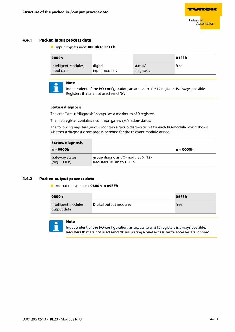
4.4.1 Packed input process data
input register area: 0000h to 01FFh
Status/ diagnosis
The area "status/diagnosis" comprises a maximum of 9 registers.
The first register contains a common gateway-/station-status.
The following registers (max. 8) contain a group diagnostic bit for each I/O-module which shows whether a diagnostic message is pending for the relevant module or not.
4.4.2 Packed output process data
output register area: 0800h to 09FFh
0000h 01FFh
intelligent modules, input data
digital input modules
status/diagnosis
free
NoteIndependent of the I/O-configuration, an access to all 512 registers is always possible. Registers that are not used send "0".
Status/ diagnosis
n + 0000h n + 0008h
Gateway status(reg. 100Ch)
group diagnosis I/O-modules 0...127(registers 1018h to 101Fh)
0800h 09FFh
intelligent modules, output data
Digital output modules free
NoteIndependent of the I/O-configuration, an access to all 512 registers is always possible. Registers that are not used send "0" answering a read access, write accesses are ignored.
D301295 0513 - BL20 - Modbus RTU 4-13

Implementation of Modbus TCP
4.5 Data width of the I/O-modules in the modbus-register area
The following table shows the data width of the BL20-I/O-modules within the modbus register area and the type of data alignment.
Table 4-5: Data width of the I/O-modules
Module Process input Process output Alignment
– Digital inputs
BL20-2DI-x 2 Bit - bit by bit
BL20-4DI-x 4 Bit - bit by bit
BL20-E-8DI-x 8 Bit - bit by bit
BL20-16DI-x 16 Bit - bit by bit
BL20-E-16DI-x 16 Bit - bit by bit
BL20-32DI-x 32 Bit - bit by bit
– Digital outputs
BL20-2DO-x - 2 Bit bit by bit
BL20-4DO-x - 4 Bit bit by bit
BL20-E-8DO-x - 8 Bit bit by bit
BL20-16DO-x - 16 Bit bit by bit
BL20-E-16DO-x - 16 Bit bit by bit
BL20-32DO-x - 32 Bit bit by bit
– Analog input modules
BL20-1AI-x 1 word word by word
BL20-2AI-x 2 words word by word
BL20-2AIH-I 12 words word by word
BL20-4AI-x 4 words word by word
BL20-E-8AI-U/I-4PT/NI 8 words word by word
– Analog outputs
BL20-1AO-x 1 word word by word
BL20-2AO-x 2 words word by word
BL20-2AOH-I 8 words 2 words word by word
BL20-E-4AO-U/I 4 words word by word
D301295 0513 - BL20 - Modbus RTU4-14

Data width of the I/O-modules in the modbus-register area
A The process data of the SWIRE-modules is mapped into the register area for the digital in- and output modules.
– Technology modules
BL20-1RS××× 4 words 4 words word by word
BL20-1SSI 4 words 4 words word by word
BL20-E-2CNT-2PWM 12 words 12 words word by word
BL20-E-SWIRE A 4 words 4 words word by word
BL20-2RFID-S 12 words 12 words word by word
– Power distribution modules
BL20-BR-× -
BL20-PF-× -
Table 4-5: Data width of the I/O-modules
Module Process input Process output Alignment
D301295 0513 - BL20 - Modbus RTU 4-15

Implementation of Modbus TCP
4.6 Register 0×100C: "Gateway status"
This register contains a general gateway/ station status.
4.7 Register 0×113C und 0×113D: "Restore Modbus-Connection-Parameters"
Registers 0×113C and 0×113D serve for resetting the parameter-register 0×1120 and 0×1130 to 0×113B to the default settings.
For this purpose, write "0×6C6F" in register 0×113C. To activate the reset of the registers, write "0×6164" ("load") within 30 seconds in register 0×113D.
Both registers can also be written with one single request using the function codes FC16 and FC23.
The service resets the parameters without saving them. This can be achieved by using a following "save" service.
Table 4-6: Register 100Ch: Gateway status
Bit Name Description
Gateway
15 I/O Controller Error The communication controller for the I/O-system is defective.
14 Force Mode Active Error The Force Mode is activated, which means, the actual output values may no match the ones defined and sent by the field bus.
13 reserved -
12 Modbus Wdog Error A timeout occurred in the modbus-communication.
Module bus
11 I/O Cfg Modified Error The I/O-configuration has be changed and is no longer compatible.
10 I/O Communication Lost Error
No Communication on the module bus.
Voltage errors
9 Usys too low System supply voltage too low (< 18 V DC).
8 Usys too high System supply voltage too high (> 30 V DC).
7 UL too low Load voltage too low (< 18 V DC).
Warnings
3 I/O Cfg Modified Warning The station configuration has changed.
0 I/O Diags Active Warning At least one I/O-module sends active diagnosis.
D301295 0513 - BL20 - Modbus RTU4-16

Register 0×113E und 0×113F: "Save Modbus-Connection-Parameters"
4.8 Register 0×113E und 0×113F: "Save Modbus-Connection-Parameters"
Registers 0×113E and 0×113F are used for the non-volatile saving of parameters in registers 0×1120 and 0×1130 to 0×113B.
or this purpose, write "0×7361" in register 0×113E. To activate the saving of the registers, write "0×7665" ("save") within 30 seconds in register 0×113F.
Both registers can also be written with one single request using the function codes FC16 and FC23.
4.9 The Service-Object
The service-object is used to execute one-time or acyclic services. It is an acknowledge service which may serve, for example, to parameterize an I/O-module.
The service request area allows write access, the service response area only read access.
service request area
The register service no. in the request area can contain a user defined value which is deleted after the execution of the service.
The register service code specifies which service is requested.
The register index/addr is optional and the meaning depends on the particular service.
The register data-reg-count contains, depending on the service, the number (0 to 122) of the transferred or of the requested data registers.
Depending on the service, the optional data area can contain additional parameters and/or other data to be written.
Service-response-area
After the execution of a request, the registers service-no., service code and index/addr in the response area contain a copy of the values in the request area.
The register result shows whether the execution was successful or not.
2000h 2080h 20FFh
service request area service response area
2000h 2001h 2002h 2003h 2004h 2005h 207Fh
Service-number
reserved Service code
Index/ addr Data-Reg-Count
optional data (0...122 registers)
2080h 2081h 2082h 2083h 2084h 2085h 20FFh
Service-number
result Service code
Index/ addr Data-Reg-Count
optional data (0...122 registers)
NoteThe service no. is thus used for a simple handshake on the application level. The application increases the service no. with every request. The service is blocked, until the service number in the request area matches the service number in the response area.
D301295 0513 - BL20 - Modbus RTU 4-17

Implementation of Modbus TCP
The register data-reg-count contains the number of data registers (0 to 122).
The optional data area can contain, depending on the service, the requested data.
Supported service numbers:
A service request may have the following results:
Table 4-7: Supported service numbers
Service code Meaning
0×0000 no function
0×0003 indirect reading of registers
0×0010 indirect writing of registers
Table 4-8: results of the service request
Service code Meaning
0×0000 error free execution of service
0×FFFE service parameters incorrect/ inconsistent
0×FFFF service code unknown
NoteThe services "indirect reading of registers" and "indirect writing of registers" offer an additional possibility to access any Modbus register.
Current Modbus-masters support only a limited number of register-areas that can be read or written during the communication with a Modbus-server. These areas can not be changed during operation.
In this case, the services mentioned above enables non-cyclic access to registers.
D301295 0513 - BL20 - Modbus RTU4-18

The Service-Object
Indirect reading of registers
1 to 122 (Param. Count) Modbus-registers are read, starting with address x (Addr).
service-request
service response
Indirect writing of registers
1 to 122 (Param. Count) Modbus-registers are read, starting with address Addr.)
service-request
service response
2000h 2001h 2002h 2003h 2004h 2005h 207Fh
Service-number
0×0000 0×0003 Addr Count no meaning
2080h 2081h 2082h 2083h 2084h 2085h 20FFh
Service-number
result 0×0003 Addr Count register contents
2000h 2001h 2002h 2003h 2004h 2005h 207Fh
Service-number
0×0000 0×0010 Addr Count register contents
2080h 2081h 2082h 2083h 2084h 2085h 20FFh
Service-number
result 0×0010 Addr Count no meaning
D301295 0513 - BL20 - Modbus RTU 4-19

Implementation of Modbus TCP
4.10 Bit areas: mapping of input-discrete- and coil-areas
The digital in- and outputs can be read and written (for outputs) as registers in the data area of the packed in- and output process data.
In order to set for example a single output (single coil), the following functions are available for reading and writing single bits:
FC1 ("Read Coils"),
FC2 ("Read Discrete Inputs"),
FC 5 ("Write Single Coil")
FC15 ("Write Multiple Coils")
Data mapping in the input-discrete- and coil-areas:
Mapping Mapping: input-discrete-areaAll digital inputs are stored in this area (offset "0").
Mapping Mapping: Coil-areaAll digital outputs are stored in this area (offset "0").
4.11 Error behavior of outputs (watchdog)
In case of a failure of the Modbus communication, the outputs’ behavior is as follows, depending on the defined time for the Watchdog (register 0x1120, page 4-7):
watchdog = 0 ms (default)→ outputs hold the momentary value
watchdog > 0 ms→ outputs switch to 0 after the watchdog time has expired (setting in register 0×1120).
NoteIn the packed process data, the digital I/O data are stored following the variable in- and output data area of the intelligent modules, which means they are stored with a variable offset, depending on the station’s I/O-configuration.
NotePlease observe that changes in the watchdog time have to be saved per save-command (see Register 0×113E und 0×113F: "Save Modbus-Connection-Parameters" (page 4-17)).
NoteSetting the outputs to predefined substitute values is not possible in Modbus. Eventually parameterized substitute values will not be used.
D301295 0513 - BL20 - Modbus RTU4-20

Parameters of the modules.
4.12 Parameters of the modules.
4.12.1 Digital input modules
BL20-4DI-NAMUR
Table 4-9: Module param-eters
A defaultsetting
Byte Bit Parameter name Value
– Meaning
0 to 3 0 input filter x 0 = deactivate – (input filter 0,25 ms) A
1 = activate – (input filter 2,5 ms)
1 digital input x 0 = normal A1 = inverted
2 Short circuit monitoring x 0 = deactivate A1 = activate
3 Short circuit diagnosis x 0 = deactivate A1 = activate
4 Open circuit monitoring x 0 = deactivate A1 = activate
5 Open circuit diagnosis x 0 = deactivate A1 = activate
6 Input on diagnostic x 0 = output substitute value A1 = keep last value
7 Substitute value on diag x 0 = off A 1 = on
D301295 0513 - BL20 - Modbus RTU 4-21
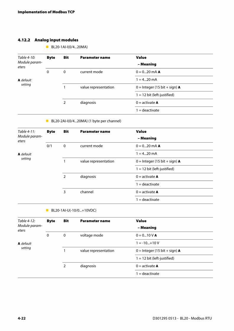
Implementation of Modbus TCP
4.12.2 Analog input modules
BL20-1AI-I(0/4...20MA)
BL20-2AI-I(0/4...20MA) (1 byte per channel)
BL20-1AI-U(-10/0...+10VDC)
Table 4-10: Module param-eters
A defaultsetting
Byte Bit Parameter name Value
– Meaning
0 0 current mode 0 = 0...20 mA A
1 = 4...20 mA
1 value representation 0 = Integer (15 bit + sign) A
1 = 12 bit (left-justified)
2 diagnosis 0 = activate A
1 = deactivate
Table 4-11: Module param-eters
A defaultsetting
Byte Bit Parameter name Value
– Meaning
0/1 0 current mode 0 = 0...20 mA A
1 = 4...20 mA
1 value representation 0 = Integer (15 bit + sign) A
1 = 12 bit (left-justified)
2 diagnosis 0 = activate A
1 = deactivate
3 channel 0 = activate A
1 = deactivate
Table 4-12: Module param-eters
A defaultsetting
Byte Bit Parameter name Value
– Meaning
0 0 voltage mode 0 = 0...10 V A
1 = -10...+10 V
1 value representation 0 = Integer (15 bit + sign) A
1 = 12 bit (left-justified)
2 diagnosis 0 = activate A
1 = deactivate
D301295 0513 - BL20 - Modbus RTU4-22

Parameters of the modules.
BL20-2AI-U(-10/0...+10VDC) (1 byte per channel)
Table 4-13: Module param-eters
A defaultsetting
Byte Bit Parameter name Value
– Meaning
0/1 0 voltage mode 0 = 0...10 V A
1 = -10...+10 V
1 value representation 0 = Integer (15 bit + sign) A
1 = 12 bit (left-justified)
2 diagnosis 0 = activate A
1 = deactivate
3 channel 0 = activate A
1 = deactivate
D301295 0513 - BL20 - Modbus RTU 4-23
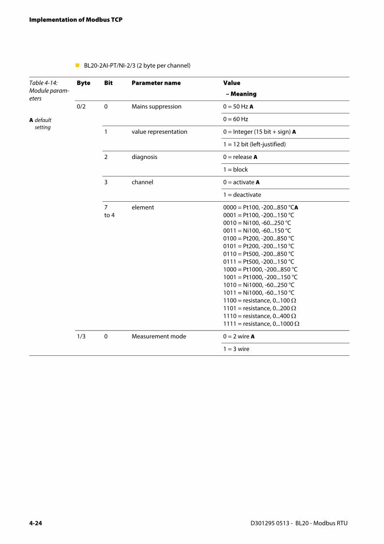
Implementation of Modbus TCP
BL20-2AI-PT/NI-2/3 (2 byte per channel)
Table 4-14: Module param-eters
A defaultsetting
Byte Bit Parameter name Value
– Meaning
0/2 0 Mains suppression 0 = 50 Hz A
0 = 60 Hz
1 value representation 0 = Integer (15 bit + sign) A
1 = 12 bit (left-justified)
2 diagnosis 0 = release A
1 = block
3 channel 0 = activate A
1 = deactivate
7 to 4
element 0000 = Pt100, -200...850 °CA0001 = Pt100, -200...150 °C0010 = Ni100, -60...250 °C0011 = Ni100, -60...150 °C0100 = Pt200, -200...850 °C0101 = Pt200, -200...150 °C0110 = Pt500, -200...850 °C0111 = Pt500, -200...150 °C1000 = Pt1000, -200...850 °C1001 = Pt1000, -200...150 °C1010 = Ni1000, -60...250 °C1011 = Ni1000, -60...150 °C1100 = resistance, 0...100 Ω1101 = resistance, 0...200 Ω1110 = resistance, 0...400 Ω1111 = resistance, 0...1000 Ω
1/3 0 Measurement mode 0 = 2 wire A
1 = 3 wire
D301295 0513 - BL20 - Modbus RTU4-24

Parameters of the modules.
BL20-2AI-THERMO-PI (2 byte parameters per channel)
BL20-4AI-U/I (1 byte parameters per channel)
Table 4-15: Module param-eters
A defaultsetting
Byte Bit Parameter name Value
– Meaning
0/1 0 Mains suppression 0 = 50 Hz A
0 = 60 Hz
1 value representation 0 = Integer (15 bit + sign) A
1 = 12 bit (left-justified)
2 diagnosis 0 = release A
1 = block
3 channel 0 = activate A
1 = deactivate
7 to 4
element 0000 = Type K, -270...1370 °CA0001 = Type B, +100....1820 °C0010 = Type E, -270...1000 °C0011 = Type J, -210...1200 °C0100 = Type N, -270...1300 °C0101 = Type R, -50...1760 °C0110 = Type S, -50...1540 °C0111 = Type T, -270...400 °C1000 = ±50 mV1001 = ±100 mV1010 = ±500 mV1011 = ±1000 mV... = reserved
Table 4-16: Module param-eters
A defaultsetting
Byte Bit Parameter name Value
– Meaning
0 to 3 0 range 0 = 0...10 V/ 0...20 mA A
1 = -10...+10 V/ 4...20 mA
1 value representation 0 = Integer (15 bit + sign) A
1 = 12 bit (left-justified)
2 diagnosis 0 = release A
1 = block
3 channel 0 = activate A
1 = deactivate
4 Operation mode 0 = voltage A
1 = current
D301295 0513 - BL20 - Modbus RTU 4-25

Implementation of Modbus TCP
BL20-2AIH-I
Table 4-17: Module param-eters
A defaultsetting
Byte Bit Parameter name Value
– Meaning
0(channel 1)
0 channel 0 = activate A
1 = deactivate
1 short circuit diagnostics 0 = block
1 = release A
2 open circuit diagnostics 0 = block
1 = release A
3 + 4 Operation mode 0 = 0...20 mA (polling of HART®-status not possible)
1 = 4...20 mA (polling of HART®-status not possible)
2 = 4…20 mA HART® active A Cyclic polling of HART®-status activated.
5 + 6 reserved
7 HART®-diagnostics 0 = release A
1 = block
1(channel 1)
0 + 1 value representation 0 = Integer (15 bit + sign) A
1 = NE 43
2 = Extended Range
2 + 3 (channel 2)
similar to byte 0 + 1
4 HART®-Variable VA Defines the channel of which the HART®-variable is read.
0 channel mapping 0 = channel 1
1 = channel 2
6 + 7 variable mapping Defines which HART-variable of the connected sensor is mapped into the module’s process data.
0= PV (primary variable)
1= SV (2nd variable)
2 = TV (3rd variable)
3 = QV (4th variable)
D301295 0513 - BL20 - Modbus RTU4-26

Parameters of the modules.
5 HART®-Variable B Defines the channel of which the HART®-variable is read.
0 channel mapping 0 = channel 1
1 = channel 2
6 + 7 variable mapping Defines which HART-variable of the connected sensor is mapped into the module’s process data.
0= PV (primary variable)
1= SV (2nd variable)
2 = TV (3rd variable)
3 = QV (4th variable)
6 HART®-variable C Defines the channel of which the HART®-variable is read.
0 channel mapping 0 = channel 1
1 = channel 2
6 + 7 variable mapping Defines which HART-variable of the connected sensor is mapped into the module’s process data.
0= PV (primary variable)
1= SV (2nd variable)
2 = TV (3rd variable)
3 = QV (4th variable)
7 HART®-variable D Defines the channel of which the HART®-variable is read.
0 channel mapping 0 = channel 1
1 = channel 2
6 + 7 variable mapping Defines which HART-variable of the connected sensor is mapped into the module’s process data.
0= PV (primary variable)
1= SV (2nd variable)
2 = TV (3rd variable)
3 = QV (4th variable)
Table 4-17: Module param-eters
A defaultsetting
Byte Bit Parameter name Value
– Meaning
D301295 0513 - BL20 - Modbus RTU 4-27

Implementation of Modbus TCP
BL20-E-8AI-U/I-4PT/Ni (1 byte per channel)
Table 4-18: Module param-eters
Byte Bit Parameter name
Value Meaning
A defaultsetting
B In 3-wire mea-surement, only the first of the used channel has too be parameterized. The parameter-ization of the second channel is ignored.
0 to 7 0 to 5 Operation mode
000000 voltage -10...10 V DC Standard A
000001 voltage 0...10 V DC Standard
000010 voltage -10...10 V DC NE 43
000011 voltage 0...10 V DC NE 43
000100 voltage -10...10 VDC, Extended Range
000101 voltage 0...10 VDC, Extended Range
000110 reserved
000111 reserved
001000 current 0...20 mA Standard
001001 current 4...20 mA Standard
001010 current 0...20 mA, NE 43
001011 current 4...20 mA, NE 43
001100 current 0...20 mA, Extended Range
001101 current 4...20 mA, Extended Range
001110 reserved
001111 reserved
010000 Pt 100, -200°C...850 °C, 2-wire
010001 Pt 100, -200°C...150 °C, 2-wire
010010 Pt 200, -200°C...850 °C, 2-wire
010011 Pt 200, -200°C...150 °C, 2-wire
010100 Pt 500, -200°C...850 °C, 2-wire
010101 Pt 500, -200°C...150 °C, 2-wire
010110 Pt 1000, -200°C...850 °C, 2-wire
010111 Pt 1000, -200°C...150 °C, 2-wire
011000 Pt 100, -200°C...850 °C, 3-wire B
011001 Pt 100, -200°C...150 °C, 3-wire B
011010 Pt 200, -200°C...850 °C, 3-wire B
011011 Pt 200, -200°C...150 °C, 3-wire B
011100 Pt 500, -200°C...850 °C, 3-wire B
011101 Pt 500, -200°C...150 °C, 3-wire B
D301295 0513 - BL20 - Modbus RTU4-28

Parameters of the modules.
0 to 7 0 to 5 Operation mode
011110 Pt 1000, -200°C...850 °C, 3-wire B
011111 Pt 1000, -200°C...150 °C, 3-wire B
100000 Ni 100, -60 °C...250 °C, 2-wire
100001 Ni 100, -60°C...150 °C, 2-wire
100010 Ni 1000, -60 °C...250 °C, 2-wire
100011 Ni 1000, -60°C...150 °C, 2-wire
100100 Ni 1000TK5000, -60 °C...250 °C, 2-wire
100101 reserved
100110 reserved
100111 reserved
101000 Ni 100, -60 °C...250 °C, 3-wire
101001 Ni 100, -60°C...150 °C, 3-wire
101010 Ni 1000, -60 °C...250 °C, 3-wire
101011 Ni 1000, -60°C...150 °C, 3-wire
101100 Ni 1000TK5000, -60 °C...250 °C, 3-wire
101101 reserved
101110 reserved
101111 reserved
110000 resistance, 0...250 Ω
110001 resistance, 0...400 Ω
110010 resistance, 0...800 Ω
110011 resistance, 0...2000 Ω
110100 resistance, 0...4000 Ω
110101to 111110
reserved
111111 deactivated
6 value representation Kx
0 Integer (15 bit + sign) A
1 12 bit (left-justified)
7 diagnostics Kx 0 release A
1 block
Table 4-18: Module param-eters
Byte Bit Parameter name
Value Meaning
D301295 0513 - BL20 - Modbus RTU 4-29
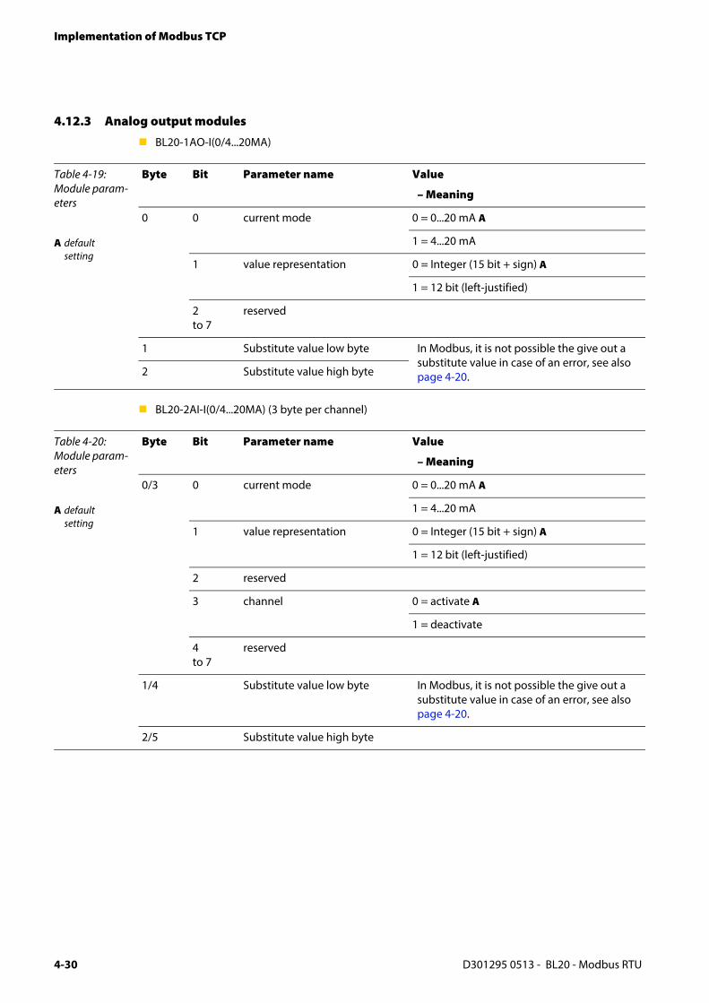
Implementation of Modbus TCP
4.12.3 Analog output modules
BL20-1AO-I(0/4...20MA)
BL20-2AI-I(0/4...20MA) (3 byte per channel)
Table 4-19: Module param-eters
A defaultsetting
Byte Bit Parameter name Value
– Meaning
0 0 current mode 0 = 0...20 mA A
1 = 4...20 mA
1 value representation 0 = Integer (15 bit + sign) A
1 = 12 bit (left-justified)
2 to 7
reserved
1 Substitute value low byte In Modbus, it is not possible the give out a substitute value in case of an error, see also page 4-20.2 Substitute value high byte
Table 4-20: Module param-eters
A defaultsetting
Byte Bit Parameter name Value
– Meaning
0/3 0 current mode 0 = 0...20 mA A
1 = 4...20 mA
1 value representation 0 = Integer (15 bit + sign) A
1 = 12 bit (left-justified)
2 reserved
3 channel 0 = activate A
1 = deactivate
4 to 7
reserved
1/4 Substitute value low byte In Modbus, it is not possible the give out a substitute value in case of an error, see also page 4-20.
2/5 Substitute value high byte
D301295 0513 - BL20 - Modbus RTU4-30

Parameters of the modules.
BL20-2AO-U(-10/0...+10VDC) (3 byte per channel)
Table 4-21: Module param-eters
A defaultsetting
Byte Bit Parameter name Value
– Meaning
0/3 0 voltage mode 0 = 0...10 V A
1 = -10...+10 V
1 value representation 0 = Integer (15 bit + sign) A
1 = 12 bit (left-justified)
2 reserved
3 channel 0 = activate A
1 = deactivate
4 to 7
reserved
1/4 Substitute value low byte In Modbus, it is not possible the give out a substitute value in case of an error, see also page 4-20.2/5 Substitute value high byte
D301295 0513 - BL20 - Modbus RTU 4-31

Implementation of Modbus TCP
BL20-2AOH-I
Table 4-22: Module param-eters
Byte Bit Parameter name Value
– Meaning
A defaultsetting
0(channel 1)
0 channel 0 = activate A
1 = deactivate
1 diagnosis 0 = block A
1 = release
3 + 4 Operation mode Kx 0 = 0...20 mA (polling of HART®-status not possible)
1 = 4...20 mA (polling of HART®-status not possible)
2 = 4…20 mA HART® active A(cyclic polling of HART-status activate)
7 HART®-diagnostics Kx 0 = release A
1 = block
1(channel 1)
0+1 value representation Kx 0 = Integer (15 bit + sign) A
1 = NE 43
2 = Extended Range
6 + 7 Behavior on module bus error Ax
In Modbus, it is not possible the give out a substitute value in case of an error, see also page 4-20.
2+3(channel 1)
substitute value Ax
4 to 7(channel 2)
similar to byte 0 to 3
8 HART®-Variable VA Defines the channel of which the HART®-variable is read.
0 channel mapping 0 = channel 1
1 = channel 2
6 + 7 variable mapping Defines which HART-variable of the connected sensor is mapped into the module’s process data.
0= PV (primary variable)
1= SV (2nd variable)
2 = TV (3rd variable)
3 = QV (4th variable)
D301295 0513 - BL20 - Modbus RTU4-32

Parameters of the modules.
A defaultsetting
9 HART®-Variable B Defines the channel of which the HART®-variable is read.
0 channel mapping 0 = channel 1
1 = channel 2
6 + 7 variable mapping Defines which HART-variable of the connected sensor is mapped into the module’s process data.
0= PV (primary variable)
1= SV (2nd variable)
2 = TV (3rd variable)
3 = QV (4th variable)
10 HART®-variable C Defines the channel of which the HART®-variable is read.
0 channel mapping 0 = channel 1
1 = channel 2
6 + 7 variable mapping Defines which HART-variable of the connected sensor is mapped into the module’s process data.
0= PV (primary variable)
1= SV (2nd variable)
2 = TV (3rd variable)
3 = QV (4th variable)
11 HART®-variable D Defines the channel of which the HART®-variable is read.
0 channel mapping 0 = channel 1
1 = channel 2
6 + 7 variable mapping Defines which HART-variable of the connected sensor is mapped into the module’s process data.
0= PV (primary variable)
1= SV (2nd variable)
2 = TV (3rd variable)
3 = QV (4th variable)
Table 4-22: Module param-eters
Byte Bit Parameter name Value
– Meaning
D301295 0513 - BL20 - Modbus RTU 4-33

Implementation of Modbus TCP
BL20-E-4AO-U/I (3 byte parameters per channel)
Table 4-23: Module param-eters
Byte Bit Parameter name Value Meaning
A defaultsetting
0/3/6/9 0 to 3 Operation mode Kx
000000 voltage -10...10 V DC Standard A
000001 voltage 0...10 V DC Standard
000010 voltage -10...10 V DC NE 43
000011 voltage 0...10 V DC NE 43
000100 voltage -10...10 VDC, Extended Range
000101 voltage 0...10 VDC, Extended Range
000110 reserved
000111 reserved
001000 current 0...20 mA Standard
001001 current 4...20 mA Standard
001010 current 0...20 mA, NE 43
001011 current 4...20 mA, NE 43
001100 current 0...20 mA, Extended Range
001101 current 4...20 mA, Extended Range
1110 reserved
1111 deactivated
4 value representation Kx
0 Integer (15 bit + sign) A
1 12 bit (left-justified)
5 diagnostics Kx 0 release A
1 block
6 + 7 substitute value options
00 output substitute value
01 hold current value
10 output min. value
11 output max. value
1/4/7/10
substitute value low byte Ax
In Modbus, it is not possible the give out a substitute value in case of an error, see also page 4-20.
2/5/8/11
substitute value Ax high byte
D301295 0513 - BL20 - Modbus RTU4-34

Parameters of the modules.
4.12.4 Technology modules
BL20-1RS232
Table 4-24: Module param-eters
Byte Bit Parameter name Value
– Meaning
A defaultsetting
0 3 to 0
Data rate 0000 = 300 bps0001 = 600 bps0010 = 1200 bps0100 = 2400 bps0101 = 4800 bps0110 = 9600 bps A0111 = 14400 bps1000 = 19200 bps1001 = 28800 bps1010 = 38400 bps1011 = 57600 bps1100 = 115200 bps... reserved
5, 4 reserved
6 DisableReducedCtrl Constant setting:The diagnostic messages are shown in Byte 6 of the process input data (independently from "Diagnosis"). Byte 6 of the process output data contains 2 bits, with which the receive or transmit buffer can be cleared.Byte 7 contains the status or control byte. User data are represented in Bytes 0 - 5.
0 7 diagnosis 0 = release A– Diagnostic activated:
This affects the separate fieldbus-specific diagnostic message – not the diagnosis embedded in the process input data.
1 = block
D301295 0513 - BL20 - Modbus RTU 4-35

Implementation of Modbus TCP
A defaultsetting
1 0 Stop bits 0 = 1 bit A
1 = 2 bit
2,1 Parity 00 = none
01 = odd A– The parity bit is set so that the total number
of bits (data bits plus parity bit) set to 1 is odd.
10 = even– The parity bit is set so that the total number
of bits (data bits plus parity bit) set to 1 is odd.
3 Data bits 0 = 7 A– The number of data bits is 7.
1 + 8– The number of data bits is 8.
1 4 to 5
Flow control 00 = none A– Data flow control is switched off.
01 = XON/XOFF – Software handshake (XON/XOFF) is
switched on.10 = RTS/CTS
– Hardware handshake (RTS/CTS) is switched on.
7.6 reserved
2 XON character 0 – 255 (17 A)XON characterThis character is used to start the transmission of data from the data terminal device if the software handshake is active.
3 XOFF character 0 – 255 (19 A)XOFF characterThis character is used to start the transmission of data from the data terminal device if the software handshake is active.
Table 4-24: Module param-eters
Byte Bit Parameter name Value
– Meaning
D301295 0513 - BL20 - Modbus RTU4-36

Parameters of the modules.
BL20-1RS485/422
Table 4-25: Module param-eters
Byte Bit Parameter name Value
– Meaning
A defaultsetting
0 3 to 0 Data rate 0000 = 300 bps0001 = 600 bps0010 = 1200 bps0100 = 2400 bps0101 = 4800 bps0110 = 9600 bps A0111 = 14400 bps1000 = 19200 bps1001 = 28800 bps1010 = 38400 bps1011 = 57600 bps1100 = 115200 bps... reserved
4 Select RS485 0 = parameterization of the module as RS422
1 = parameterization of the module as RS485
5 reserved
6 DisableReducedCtrl Constant setting:The diagnostic messages are shown in Byte 6 of the process input data (independently from "Diagnosis"). Byte 6 of the process output data contains 2 bits, with which the receive or transmit buffer can be cleared.Byte 7 contains the status or control byte. User data are represented in Bytes 0 - 5.
0 7 diagnosis 0 = release A
1 = block
D301295 0513 - BL20 - Modbus RTU 4-37
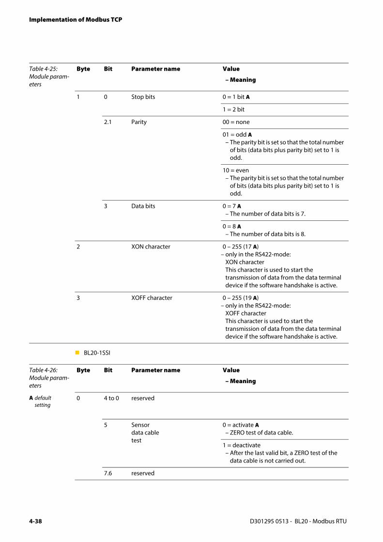
Implementation of Modbus TCP
BL20-1SSI
1 0 Stop bits 0 = 1 bit A
1 = 2 bit
2.1 Parity 00 = none
01 = odd A– The parity bit is set so that the total number
of bits (data bits plus parity bit) set to 1 is odd.
10 = even– The parity bit is set so that the total number
of bits (data bits plus parity bit) set to 1 is odd.
3 Data bits 0 = 7 A– The number of data bits is 7.
0 = 8 A– The number of data bits is 8.
2 XON character 0 – 255 (17 A)– only in the RS422-mode:
XON characterThis character is used to start the transmission of data from the data terminal device if the software handshake is active.
3 XOFF character 0 – 255 (19 A)– only in the RS422-mode:
XOFF characterThis character is used to start the transmission of data from the data terminal device if the software handshake is active.
Table 4-26: Module param-eters
Byte Bit Parameter name Value
– Meaning
A defaultsetting
0 4 to 0 reserved
5 Sensordata cabletest
0 = activate A– ZERO test of data cable.
1 = deactivate – After the last valid bit, a ZERO test of the
data cable is not carried out.
7.6 reserved
Table 4-25: Module param-eters
Byte Bit Parameter name Value
– Meaning
D301295 0513 - BL20 - Modbus RTU4-38

Parameters of the modules.
1 3 to 0 Number of invalid bits(LSB)
0000 to 1111Number of invalid bits on the LSB side of the position value supplied by the SSI encoder. The meaningful word width of the position value transferred to the module bus master is as follows: SSI_FRAME_LEN -INVALID_BITS_MSB- INVALID_BITS_LSB. The invalid bits on the LSB side are removed by shifting the position value to the right, starting with the LSB. (Default 0 bit = 0×0). INVALID_BITS_MSB +INVALID_BITS_LSB must always be less than SSI_FRAME_LEN.
1 6 to 4 Number of invalid bits (MSB) 000 to 111Number of invalid bits on the LSB side of the position value supplied by the SSI encoder. The meaningful word width of the position value transferred to the module bus master is as follows: SSI_FRAME_LEN - INVALID_BITS_MSB - INVALID_BITS_LSB. Number of invalid bits on the MSB side of the position value supplied by the SSI encoder. INVALID_BITS_MSB +INVALID_BITS_LSB must always be less than SSI_FRAME_LEN. Default: 0 = 0hex
7 reserved
A defaultsetting
2 3 to 0 Data rate 0000 = 1000000 bps0001 = 500000 bps A0010 = 250000 bps0011 = 125000 bps0100 = 100000 bps0101 = 83000 bps0110 = 71000 bps0111 = 62500 bps... reserved
7 to 4 reserved
Table 4-26: Module param-eters
Byte Bit Parameter name Value
– Meaning
D301295 0513 - BL20 - Modbus RTU 4-39

Implementation of Modbus TCP
3 5 to 0 Number of data frame bits
00000 to 100000Number of bits of the SSI data frame. SSI_FRAME_LEN must always be greater than INVALID_BITS.Default: 25 = 19hex
6 reserved
7 Data type binary coded A– SSI encoder sends data in binary code
GRAY coded– SSI encoder sends data in GRAY code
Table 4-26: Module param-eters
Byte Bit Parameter name Value
– Meaning
D301295 0513 - BL20 - Modbus RTU4-40

Parameters of the modules.
BL20-E-1SWIRE
The following table shows the meaning of the parameter bits:
Bit 7 Bit 6 Bit 5 Bit 4 Bit 3 Bit 2 Bit 1 Bit 0Byte 1 reserved free free MC MNA configura
tionDisable
Cfgfree
Byte 2 free UAUXERR TYPERR TYPINFO PKZERR PKZINFO SDERR SDINFO
Byte 3 reserved
Byte 4 reserved (life guarding time until version VN 01-03)
Byte 5 SCDIAGS8 SCDIAGS7 SCDIAGS6 SCDIAGS5 SCDIAGS4 SCDIAGS3 SCDIAGS2 SCDIAGS1
Byte 6 SCDIAGS16 SCDIAGS15 SCDIAGS14 SCDIAGS13 SCDIAGS12 SCDIAGS11 SCDIAGS10 SCDIAGS9
Byte 7 reserved
Byte 8 reserved
Byte 9 - 24
Type designation slave 1 - 16
Table 4-27: Module param-eters
Parameter name
Value
Byte 1
A defaultsetting
Disable Cfg If the physical structure of the SWIRE bus does not match the configuration stored in the BL20-E-1SWIRE on power up (SW LED flashing), the physical structure of the SWIRE bus must be stored in the BL20-E-1SWIRE.
0 = inactive A Manual SWIRE configuration:To store the physical structure of the SWIRE bus in the BL20-E-1SWIRE, the CFG button of the BL20-E-1SWIRE must be pressed manually (only functions if the SW LED is flashing).
1 = active Automatic SWIRE configuration:If the physical structure of the SWIRE bus does not match the configuration stored in the BL20-E-1SWIRE on power up, the physical structure is stored automatically in the BL20-E-1SWIRE.
configura-tion
PLC configuration check If the PLC configuration check is activated, the configuration stored in the BL20-E-1SWIRE is compared with the SET configuration stored in the PLC.
0 = active A The configuration stored in BL20-E-1SWIRE is compared with the SET configuration stored in the PLC. Only SWIRE slaves in the SWIRE bus are accepted that have a device ID completely matching the SET configuration..
1 = inactive All slaves are mapped in 4Bit INPUT/ 4Bit OUTPUT without checking the device ID.
D301295 0513 - BL20 - Modbus RTU 4-41

Implementation of Modbus TCP
Byte 1
MNAactive/ passive
Configuration checkBus or slave-oriented configuration check (without function if MC = 1)
0 = Bus based A
If the PLC configuration check is activated, data exchange is only started if the configuration stored in the BL20-E-1SWIRE fully matches the SET configuration stored in the PLC. Modifying the bus during operation causes the system to be aborted.
1 = Slave based
If the PLC configuration check is activated, data exchange is started with all SWIRE slaves that match the SET configuration stored in the PLC. The SWIRE slaves that do not match the SET configuration stored in the PLC do not perform any data exchange.
MC Moeller conformance (from version VN 01-04)Behavior of the BL20-E-1SWIRE in accordance with SWIRE Conformance criteria.
inactive A Default behavior
active The BL20-E-1SWIRE master responds according to the Moeller SWIRE Conformance criteria (see manual for the IO-modules D300717).
SDINFO Slave error fieldActivate slave diagnostics info field SDERRSx. As soon as a slave on the bus clears its PKZ bit, this is indicated as an individual error depending on the parameter setting.
active Single diagnostics is activated
inactive Single diagnostics is not activated
Byte 2
SDERR Group error - slave errorActivate slave diagnostics SDERRSx. Activate slave diagnostics SDERRSx. As soon as only one slave on the bus sets its error bit, this is indicated as a group error depending on the parameter setting.
0 = active A Group diagnostics is activated
1 = inactive Group diagnostics is not activated
PKZINFO PKZ error fieldActivate slave diagnostics info field PKZERRSx. As soon as a slave on the bus clears its PKZ bit, this is indicated as an individual error depending on the parameter setting.
0 = active A Single diagnostics is activated
1 = inactive Single diagnostics is not activated
Table 4-27: Module param-eters
Parameter name
Value
D301295 0513 - BL20 - Modbus RTU4-42

Parameters of the modules.
Byte 2
PKZERR Group PKZ error fieldActivate slave diagnostics PKZERR. As soon as a slave on the bus clears its PKZ bit, this is indicated as an individual error depending on the parameter setting.
0 = active A Group diagnostics is activated
1 = inactive Group diagnostics is not activated
TYPINFO Configuration error fieldAs soon as a slave on the bus does not match the set configuration and therefore cannot be started, this is indicated as an individual error depending on the parameter set.
0 = active A Single diagnostics is activated
1 = inactive Single diagnostics is not activated
TYPERR Group configuration error fieldActivate slave diagnostics TYPERRSx. As soon as only one slave on the bus is incorrectly configured, this is indicated as an error depending on the parameter setting.
0 = active A Group diagnostics is activated
1 = inactive Group diagnostics is not activated
Byte 2
UAUXERR Error message voltage UAUXActivate system diagnostics UAUXERR. UAUXERR will generate an error message as soon as the power supply goes below a level at which the function of the relays is not guaranteed.
0 = active A Error message UAUXERR activated
1 = inactive Error message UAUXERR not activated
Byte 3 reserved
Byte 4
reserved (Lifeguarding time only up to version VN01-03)
Was up to version VN 01-03: Lifeguarding time of the SWIRE slaves. Lifeguarding time of the SWIRE slaves
0x02-0xFF0x64 A
Lifeguarding time of the SWIRE slavesSetting of lifeguarding time of SWIRE slaves, timeout time up to automatic reset of the slaves in the event of communication failure. (n * 10ms) (Default 1s)0xFF: Lifeguarding off
Byte 5 - 6
Table 4-27: Module param-eters
Parameter name
Value
D301295 0513 - BL20 - Modbus RTU 4-43

Implementation of Modbus TCP
BL20-E-2CNT-2PWM (see separate manual for this module D301224)
BL20-2RFID-S (see RFID-documentation www.turck.de)
SDDIAGSx Input bit communication error, slave xSlave diagnostics message from Byte 1 / Bit 7 is accepted in the feedback interface as Bit 4
0 = active A SDDIAGSx is accepted
1 = inactive SDDIAGSx is not accepted
Byte 7 - 8 reserved
Byte 9 to 24
Device ID, slave x
TYPE setting for the LIN slave at position x on the SWIRE bus
0x20 SWIRE-DIL-MTB (: 0xFF)
0xFF Basic setting (no slave)
Table 4-27: Module param-eters
Parameter name
Value
D301295 0513 - BL20 - Modbus RTU4-44

Diagnostic messages of the modules
4.13 Diagnostic messages of the modules
4.13.1 Power distribution modules
BL20-BR-24VDC-D
BL20-PF-24VDC
BL20-PF-120/230VAC-D
Table 4-28: BL20-BR-24VDC-D
Diagnostic byte Bit diagnosis
n 0 Module bus voltage warning
1 reserved
2 Undervoltage field supply
3 reserved
Table 4-29: BL20-PF-24VDC
Diagnostic byte Bit diagnosis
n 0 reserved
1 reserved
2 Undervoltage field supply
reserved
Table 4-30: BL20-PF-120/230VAC-D
Diagnostic byte Bit diagnosis
n 0 reserved
1 reserved
2 Undervoltage field supply
reserved
D301295 0513 - BL20 - Modbus RTU 4-45
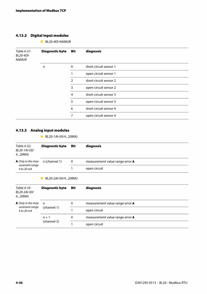
Implementation of Modbus TCP
4.13.2 Digital input modules
BL20-4DI-NAMUR
4.13.3 Analog input modules
BL20-1AI-I(0/4...20MA)
BL20-2AI-I(0/4...20MA)
Table 4-31: BL20-4DI-NAMUR
Diagnostic byte Bit diagnosis
n 0 short circuit sensor 1
1 open circuit sensor 1
2 short circuit sensor 2
3 open circuit sensor 2
4 short circuit sensor 3
5 open circuit sensor 3
6 short circuit sensor 4
7 open circuit sensor 4
Table 4-32: BL20-1AI-I(0/4...20MA)
Diagnostic byte Bit diagnosis
A Only in the mea-surement range 4 to 20 mA
n (channel 1) 0 measurement value range error A
1 open circuit
Table 4-33: BL20-2AI-I(0/4...20MA)
Diagnostic byte Bit diagnosis
A Only in the mea-surement range 4 to 20 mA
n (channel 1)
0 measurement value range error A
1 open circuit
n + 1 (channel 2)
0 measurement value range error A
1 open circuit
D301295 0513 - BL20 - Modbus RTU4-46

Diagnostic messages of the modules
BL20-1AI-U(-10/0...+10VDC)
BL20-2AI-U(-10/0...+10VDC)
BL20-2AI-PT/NI-2/3
BL20-2AI-THERMO-PI
Table 4-34: BL20-1AI-U(-10/0...+10VDC)
Diagnostic byte Bit diagnosis
n (channel 1) 0 Measurement value range error
Table 4-35: BL20-2AI-U(-10/0...+10VDC)
Diagnostic byte Bit diagnosis
n (channel 1) 0 Measurement value range error
n (channel 2) 0 Measurement value range error
Table 4-36: BL20-2AI-PT/NI-2/3
Diagnostic byte Bit diagnosis
A threshold: 1 % of the positive measurement range end value
B threshold:5 Ω (loop resis-tance)
n (channel 1) 0 measurement value range error A(Underflow diagnostics in temperature measurement ranges only)
1 open circuit
2 Short circuit B (in temperature measurement ranges only)
3 to 7
Table 4-37: BL20-2AI-THERMO-PI
Diagnostic byte Bit diagnosis
A threshold: 1 % of the posi-tive measure-ment range end value
n 0 measurement value range error A
1 open circuit(in temperature measurement ranges only)
2 to 7 reserved
D301295 0513 - BL20 - Modbus RTU 4-47

Implementation of Modbus TCP
BL20-2AIH-I
BL20-4AI-U/I
Table 4-38: BL20-2AIH-I
Diagnostic byte Bit diagnosis
n 0 overflowThe measurement value exceeds the value ranges and the device is not able to capture these values.
1 open circuitDisplays an open circuit in the signal line.
2 Short circuitDisplays a short circuit in the signal line.
3 undervoltageThe measurement value is below the value ranges and the device is not able to capture these values.
4 HART® status-error The connected HART®-device set a bit in the HART® status-information ("status - polling").
5 HART® communication error The channel does not allow communication with the HART®-device.
6 Invalid parameter
7 Hardware errorShows common errors of the module hardware. The return analog value in case of an error is "0".
Table 4-39: BL20-4AI-U/I
Diagnostic byte Bit diagnosis
A threshold: 1 % of the posi-tive measure-ment range end value, under-flow diagnostics only in value range 4...20 mA
B threshold: 3 mA (only in value range 4...20 mA)
n (channel 0) to n + 3 (channel 3)
0 measurement value range error A
1 open circuit B
2 to 7 reserved
D301295 0513 - BL20 - Modbus RTU4-48

Diagnostic messages of the modules
BL20-E-8AI-U/I-4AI-PT/NI
4.13.4 Digital output modules
BL20-2DO-24VDC-0.5A-P
BL20-2DO-24VDC-0.5A-N
BL20-2DO-24VDC-2A-P
Table 4-40: BL20-E-8AI-U/I-4AI-PT/NI
Diagnostic byte Bit diagnosis
A thresholds: value represen-tation of the module in man-ual D300716
n (channel 0) to n + 7 (channel 7)
0 Measurement value range error (OoR) A
1 Wire break (WB) A
2 Short circuit (SC) A
3 Overflow/ underflow (OUFL) A
4 to 6 reserved
7 Hardware error
Table 4-41: BL20-2DO-24VDC-0.5A-P
Diagnostic byte Bit diagnosis
n 0 overcurrent (short-circuit channel 1)
1 overcurrent (short-circuit channel 2)
Table 4-42: BL20-2DO-24VDC-0.5A-N
Diagnostic byte Bit diagnosis
n 0 overcurrent (short-circuit channel 1)
1 overcurrent (short-circuit channel 2)
Table 4-43: BL20-2DO-24VDC-2A-P
Diagnostic byte Bit diagnosis
n 0 overcurrent (short-circuit channel 1)
1 overcurrent (short-circuit channel 2)
D301295 0513 - BL20 - Modbus RTU 4-49

Implementation of Modbus TCP
BL20-4DO-24VDC-0.5A-P
BL20-16DO-24VDC-0.5A-P
BL20-32DO-24VDC-0.5A-P
Table 4-44: BL20-4DO-24VDC-0.5A-P
Diagnostic byte Bit diagnosis
n 0 Overcurrent /short-circuit (1 ch. min)
Table 4-45: BL20-16DO-24VDC-0.5A-P
Diagnostic byte Bit diagnosis
n 0 Overcurrent (short-circuit channel 1-4)
1 Overcurrent (short-circuit channel 5-8)
2 Overcurrent (short-circuit channel 9-12)
3 Overcurrent (short-circuit channel 13-16)
Table 4-46: BL20-32DO-24VDC-0.5A-P
Diagnostic byte Bit diagnosis
n 0 Overcurrent (short-circuit channel 1-4)
1 Overcurrent (short-circuit channel 5-8)
2 Overcurrent (short-circuit channel 9-12)
3 Overcurrent (short-circuit channel 13-16)
4 Overcurrent (short-circuit channel 17-20)
5 Overcurrent (short-circuit channel 21-24)
6 Overcurrent (short-circuit channel 25-28)
7 Overcurrent (short-circuit channel 29-32)
D301295 0513 - BL20 - Modbus RTU4-50

Diagnostic messages of the modules
4.13.5 Analog output modules
BL20-2AOH-I
BL20-E-4AO-U/I
Table 4-47: BL20-2AOH-I
Diagnostic byte Bit diagnosis
n 0 Value above upper limitDisplay of a measurement range exceeding→ limit values according to parameterization
1 open circuitShows a wire break in the signal line.
2 invalid valueThe output value exceeds the values which the module is able to interpret.
3 value below lower limitDisplay of a measurement range underflow → limit values according to parameterization
4 HART® status-error The connected HART®-device set a bit in the HART® status-information ("status - polling").
5 HART® communication error The channel does not allow communication with the HART®-device.
6 Invalid parameter
7 Hardware errorShows common errors of the module hardware. The return analog value in case of an error is "0".
Table 4-48: BL20-E-4AO-U/I
Diagnostic byte Bit diagnosis
A thresholds: value represen-tation of the module in man-ual D300716
n (channel 0) to n + 3 (channel 3)
0 Measurement value range error (OoR) A
1 reserved
2 reserved
3 Overflow/ underflow (OUFL) A
4 to 6 reserved
7 Hardware error
D301295 0513 - BL20 - Modbus RTU 4-51

Implementation of Modbus TCP
4.13.6 Technology modules
BL20-1RS232
BL20-1RS485/422
BL20-1SSI
Table 4-49: BL20-1RS232
Diagnostic byte Bit diagnosis
n 0 parameterization error
1 hardware failure
2 data flow control error
3 frame error
4 buffer overflow
Table 4-50: BL20-1RS485/422
Diagnostic byte Bit diagnosis
n 0 parameterization error
1 hardware failure
2 data flow control error (only in the RS422-mode)
3 frame error
4 buffer overflow
Table 4-51: BL20-1SSI
Diagnostic byte Bit diagnosis
n 0 SSI group diagnostics
1 open circuit
2 sensor value overflow
3 sensor value underflow
4 parameterization error
D301295 0513 - BL20 - Modbus RTU4-52

Diagnostic messages of the modules
BL20-E-1SWIRE
The following table shows the meaning of the diagnostic bits:
Bit 7 Bit 6 Bit 5 Bit 4 Bit 3 Bit 2 Bit 1 Bit 0
Byte n GENERALE
RR
USWERR free COMERR free RDYERR free SWERR
Byte n+1 free UAUXERR TYPERR free PKZERR free SDERR free
TYPERR field
Byte n+2 TYPERRS8 TYPERRS7 TYPERRS6 TYPERRS5 TYPERRS4 TYPERRS3 TYPERRS2 TYPERRS1
Byte n+3 TYPERRS16 TYPERRS15 TYPERRS14 TYPERRS13 TYPERRS12 TYPERRS11 TYPERRS10 TYPERRS9
Slave diagnosis
Byte n+4 SDERRS8 SDERRS7 SDERRS6 SDERRS5 SDERRS4 SDERRS3 SDERRS2 SDERRS1
Byte n+5 SDERRS16 SDERRS15 SDERRS14 SDERRS13 SDERRS12 SDERRS11 SDERRS10 SDERRS9
PKZ field
Byte n+6 PKZERRS8 PKZERRS7 PKZERRS6 PKZERRS5 PKZERRS4 PKZERRS3 PKZERRS2 PKZERRS1
Byte n+7 PKZERRS16 PKZERRS15 PKZERRS14 PKZERRS13 PKZERRS12 PKZERRS11 PKZERRS10 PKZERRS9
Table 4-52: Meaning of the diagnostic bits
Designation
Value
Meaning
Byte 1
SWERR SWIRE MASTER
If the physical structure of the SWIRE bus does not match the configuration stored in the BL20-E-1SWIRE, this bit indicates an error.
0 Data exchange The physical structure of the SWIRE bus was accepted and the SWIRE bus is in operation.
1 Offline The physical structure was not accepted, the SWIRE bus does not start operation (SW LED flashing).
RDYERR SPS SLAVE
This bit indicates an error if the configuration stored in the BL20-E-1SWIRE does not match the SET configuration stored in the PLC.
0 Data exchange No error present. The SWIRE bus is ready for data exchange.
1 Offline The configuration stored in the BL20-E-1SWIRE was not accepted. The data exchange is prevented (RDY LED flashing).
D301295 0513 - BL20 - Modbus RTU 4-53

Implementation of Modbus TCP
COMERR Communication SWIRE
A communication error is present, such as a slave is no longer reached, its internal timeout has elapsed or communication is faulty. The master cannot carry out data exchange with at least one slave.
0 OK No error present.
1 faulty An error is present.
USWERR Voltage USW
Voltage fault in USW, voltage (17 VDC) for supplying the SWIRE slaves
0 OK No error present.
1 Under voltage An error is present.
GENE-RALERR
Error message
The creation of a function block shows that systems/function blocks for the general checking of a slave for any diagnostics messages present only check the first byte.
0 none No diagnostics message present
1 present One/several diagnostics messages present
Byte 2
SDERR Communication SWIRE slave
If the parameter SDERRA is set for group diagnostics, this bit indicates an error as soon as only one slave on the bus sets its SDERR.
0 OK No error is present or diagnostics function has been deactivated via the parameter setting.
1 faulty An error is present.
PKZERR Overcurrent protective circuit-breaker
If the parameter PKZERRA is set for group diagnostics, this bit indicates an error as soon as only one PKZ of a slave has tripped.
0 OK No PKZ error is present or diagnostics function has been deactivated via the parameter setting.
1 Tripping At least one PKZ has tripped.
Table 4-52: Meaning of the diagnostic bits
Designation
Value
Meaning
D301295 0513 - BL20 - Modbus RTU4-54
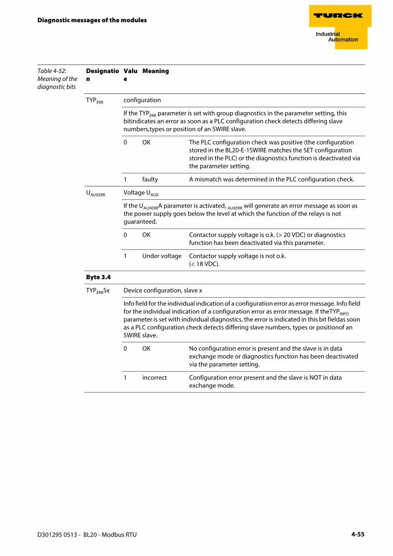
Diagnostic messages of the modules
TYPERR configuration
If the TYPERR parameter is set with group diagnostics in the parameter setting, this bitindicates an error as soon as a PLC configuration check detects differing slave numbers,types or position of an SWIRE slave.
0 OK The PLC configuration check was positive (the configuration stored in the BL20-E-1SWIRE matches the SET configuration stored in the PLC) or the diagnostics function is deactivated via the parameter setting.
1 faulty A mismatch was determined in the PLC configuration check.
UAUXERR Voltage UAUX
If the UAUXERRA parameter is activated, AUXERR will generate an error message as soon as the power supply goes below the level at which the function of the relays is not guaranteed.
0 OK Contactor supply voltage is o.k. (> 20 VDC) or diagnostics function has been deactivated via this parameter.
1 Under voltage Contactor supply voltage is not o.k. (< 18 VDC).
Byte 3.4
TYPERRSx Device configuration, slave x
Info field for the individual indication of a configuration error as error message. Info field for the individual indication of a configuration error as error message. If theTYPINFO parameter is set with individual diagnostics, the error is indicated in this bit fieldas soon as a PLC configuration check detects differing slave numbers, types or positionof an SWIRE slave.
0 OK No configuration error is present and the slave is in data exchange mode or diagnostics function has been deactivated via the parameter setting.
1 incorrect Configuration error present and the slave is NOT in data exchange mode.
Table 4-52: Meaning of the diagnostic bits
Designation
Value
Meaning
D301295 0513 - BL20 - Modbus RTU 4-55
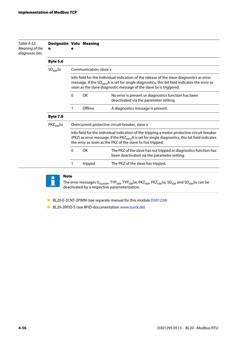
Implementation of Modbus TCP
BL20-E-2CNT-2PWM (see separate manual for this module D301224)
BL20-2RFID-S (see RFID-documentation www.turck.de)
Byte 5.6
SDERRSx Communication, slave x
Info field for the individual indication of the release of the slave diagnostics as error message. If the SDINFOA is set for single diagnostics, this bit field indicates the error as soon as the slave diagnostic message of the slave Sx is triggered.
0 OK No error is present or diagnostics function has been deactivated via the parameter setting.
1 Offline A diagnostics message is present.
Byte 7.8
PKZERRSx Overcurrent protective circuit-breaker, slave x
Info field for the individual indication of the tripping a motor-protective circuit-breaker (PKZ) as error message. If the PKZINFOA is set for single diagnostics, this bit field indicates the error as soon as the PKZ of the slave Sx has tripped.
0 OK The PKZ of the slave has not tripped or diagnostics function has been deactivated via the parameter setting.
1 tripped The PKZ of the slave has tripped.
NoteThe error messages UAUXERR, TYPERR, TYPERRSx, PKZERR, PKZERRSx, SDERR and SDERRSx can be deactivated by a respective parameterization.
Table 4-52: Meaning of the diagnostic bits
Designation
Value
Meaning
D301295 0513 - BL20 - Modbus RTU4-56

5 Application example: Modbus
5.1 Used hard-/ software..................................................................................................................................... 2
5.1.1 Hardware.................................................................................................................................................................................................25.1.2 Software...................................................................................................................................................................................................2
5.2 Configuring the hardware ............................................................................................................................ 3
5.2.1 Connection of the BL20-gateway in the example....................................................................................................................4
5.3 Operation with CoDeSys............................................................................................................................... 5
5.3.1 Predefined feature sets ......................................................................................................................................................................55.3.2 Creating a new project.......................................................................................................................................................................65.3.3 Defining the communication settings..........................................................................................................................................8
– Gateway definition ..........................................................................................................................................................................8– Setting the communication path...............................................................................................................................................9
5.3.4 Adding the Modbus COM port .................................................................................................................................................... 105.3.5 Adding the serial Modbus master............................................................................................................................................... 125.3.6 Adding a Modbus-slave .................................................................................................................................................................. 135.3.7 Programming (example program).............................................................................................................................................. 16
– Small example program ............................................................................................................................................................. 165.3.8 CoDeSys: Global variables.............................................................................................................................................................. 17
– Global variable list ........................................................................................................................................................................ 175.3.9 Modbus channels.............................................................................................................................................................................. 18
– Modbus data mapping ............................................................................................................................................................... 19– Setting the Modbus-channels (examples) and data mapping..................................................................................... 21
5.3.10 Building, login and start.................................................................................................................................................................. 305.3.11 Reading out the process data....................................................................................................................................................... 315.3.12 Diagnosis evaluation........................................................................................................................................................................ 32
– Evaluation of the Status word of the BL20-Station (%IW1) ........................................................................................... 32– Evaluation of the group diagnosis.......................................................................................................................................... 33– Evaluation of the module diagnosis information.............................................................................................................. 35
D301295 0513 - BL20 - Modbus RTU 5-1

Application example: Modbus
5.1 Used hard-/ software
5.1.1 Hardware
PLC TURCK VT250-57P-L7-DPM (V1.5.3.0)Protocol: RS485Bit rate: 9.6 kbpsData bits: 8Parity: evenStop bits: 1
SlaveBL20-E-GW-RS-MB/ET, node address 16parameterization: (default)Protocol: RS485Bit rate: 9.6 kbpsData bits: 8Parity: evenStop bits: 1
Structure of the example station:
– Slot 1: BL20-2DI-24VDC-P
– Slot 2: BL20-4DI-24VDC-P
– Slot 3: BL20-1AI-U(-10/0…+10VDC)
– Slot 4: BL20-2AI-THERMO-PI
– Slot 5: BL20-2DO-24VDC-0.5A-P
– Slot 6: BL20-E-8DO-24VDC-0.5A-P
5.1.2 Software
CoDeSys 3.5, Hotfix 1 incl:
– Modbus COM port
– Modbus-master, COM port (serial Modbus-master)
D301295 0513 - BL20 - Modbus RTU5-2

Configuring the hardware
5.2 Configuring the hardware
The BL20-gateways are delivered in "extended mode", which means with node address "0".
The electrical interface (DIP-switch "RSxxx") is pre-set to RS485.
In the "extended mode", the gateway parameters (node-address, bit rate, etc.) are set using the software tool I/O-ASSISTANT (FDT(DTM).
In the example, the gateway is set as follows using the I/O-ASSISTANT (FDT/DTM):The DIP-switches remain unaffected.
Figure 5-1: Parameteriza-tion in the DTM
D301295 0513 - BL20 - Modbus RTU 5-3

Application example: Modbus
5.2.1 Connection of the BL20-gateway in the example
The BL20-gateway is used in RS485-mode and thus connected to the VT250 as described in the following.
Figure 5-2: BL20-Gateway at VT250 inm RS485-mode 5
1
9
6
1 = RX/TX– (B) RS4852 = RxD RS2323 = TxD RS2324 = n.c.5 = GND RS2326 = RX/TX+ (A) RS4857 = RTS RS2328 = CTS RS2329 = 3,3 VDC
Unlo
ck
end
-bra
cke
tb
efo
red
ism
ountin
g
Pull
ba
rrie
rfo
rc
onfig
ura
tion
and
serv
ice
!
U L
GNDL
USYS
GNDSYS
Tx / A
Rx / B
Tx / A
Rx / B
GND
SHLD
Connector (male) at the VT250
D301295 0513 - BL20 - Modbus RTU5-4

Operation with CoDeSys
5.3 Operation with CoDeSys
Open CoDeSys via "Start → All programs → 3S CoDeSys → CoDeSys → CoDeSys V 3.5“.
5.3.1 Predefined feature sets
In this example, CoDeSys is run with the "Professional feature set" not with the "Standard feature set". This setting has influence on different CoDeSys functions and can be changed via "Tools → Options..." in the "Features" under "Predefined feature sets...". For further information concerning this topic, please read the CoDeSys online help.
Figure 5-3: Predefined fea-ture sets
D301295 0513 - BL20 - Modbus RTU 5-5

Application example: Modbus
5.3.2 Creating a new project
1 Create a new CoDeSys-project using the "File → New project" command.
2 Select "Standard project" and define a project name.
Figure 5-4: New project
Figure 5-5: Standard proj-ect
D301295 0513 - BL20 - Modbus RTU5-6
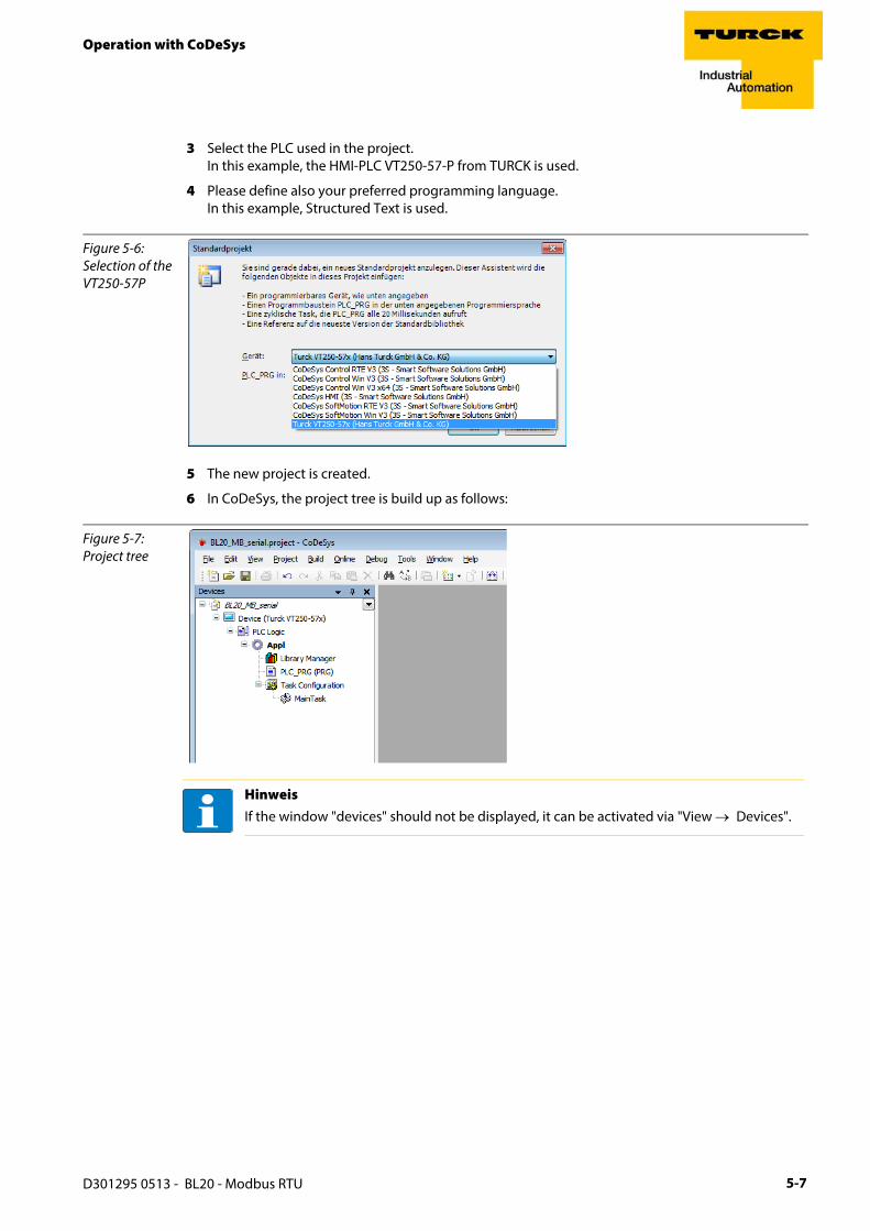
Operation with CoDeSys
3 Select the PLC used in the project. In this example, the HMI-PLC VT250-57-P from TURCK is used.
4 Please define also your preferred programming language.In this example, Structured Text is used.
5 The new project is created.
6 In CoDeSys, the project tree is build up as follows:
Figure 5-6: Selection of the VT250-57P
Figure 5-7: Project tree
HinweisIf the window "devices" should not be displayed, it can be activated via "View → Devices".
D301295 0513 - BL20 - Modbus RTU 5-7

Application example: Modbus
5.3.3 Defining the communication settings
Double-clicking the "Device Turck VT250-57x)" opens the corresponding editors.
The communication path (Gateway) to the HMI is defined in the "Communication Settings" tab.
Gateway definition
1 Use the "Add gateway"-button to open the dialog box "Gateway" and, where necessary, assign a new gateway name.
2 Keep the setting "localhost" or define an IP-address for the gateway instead.When using the setting "localhost“, the CoDeSys-communication-gateway of the PC, on which this CoDeSys-installation is running, is used as programming interface.
Figure 5-8: Communica-tion settings
D301295 0513 - BL20 - Modbus RTU5-8

Operation with CoDeSys
Setting the communication path
1 Mark the gateway and scan the network via the respective button.
2 The network card of your PC will be found and set as active path.
Figure 5-9: Setting the com-munication path
D301295 0513 - BL20 - Modbus RTU 5-9

Application example: Modbus
5.3.4 Adding the Modbus COM port
1 Open again the context menu by right-clicking the Device entry. In the dialog "Add Device" select the 3S Ethernet Adapter under "fieldbusses → Modbus → Modbus serial port" and add it to the project tree.
2 Double-clicking the Modbus COM port-entry in the project tree opens the corresponding editors.
Figure 5-10: Adding Modbus COM port as device
D301295 0513 - BL20 - Modbus RTU5-10

Operation with CoDeSys
3 In the register-tab "Modbus serial port, configuration“ set the COM-port, the bit rate and all other parameters of the communication interface.
4 Please assure, that the parameters set here correspond to the settings of the BL20-gateway.
HinweisIn our example the RS485-interface of the VT250 is used. For this reason, please select COM-port no. 2. COM-port no. 1 is the devices RS232-interface (see also D301191 "VT250-57x- Hardware description)
Figure 5-11: Modbus serial port, configura-tion
D301295 0513 - BL20 - Modbus RTU 5-11

Application example: Modbus
5.3.5 Adding the serial Modbus master
Now, click on the entry of the Modbus COM-port, select the „Modbus-Master, COM Port“ in the dialog box "Add device" and add it to the project.
Figure 5-12: Adding the serial Modbus-master
D301295 0513 - BL20 - Modbus RTU5-12

Operation with CoDeSys
5.3.6 Adding a Modbus-slave
1 Now, add a serial Modbus-slave to the project.
Figure 5-13: Selecting a slave
D301295 0513 - BL20 - Modbus RTU 5-13

Application example: Modbus
2 You can adapt the settings of the slave according to your application. Open the context menu by right-clicking the slave-entry and select the dialog-box "Properties".
Figure 5-14: Adapting the slave-properties
D301295 0513 - BL20 - Modbus RTU5-14

Operation with CoDeSys
3 Again, a double-click onto the slave in the project tree opens the respective editors.
4 In the "Modbus Slave configuration"-tab, set the node address (in this example: Address 16). All other settings can be kept.
Figure 5-15: Setting the node address at the slave
D301295 0513 - BL20 - Modbus RTU 5-15
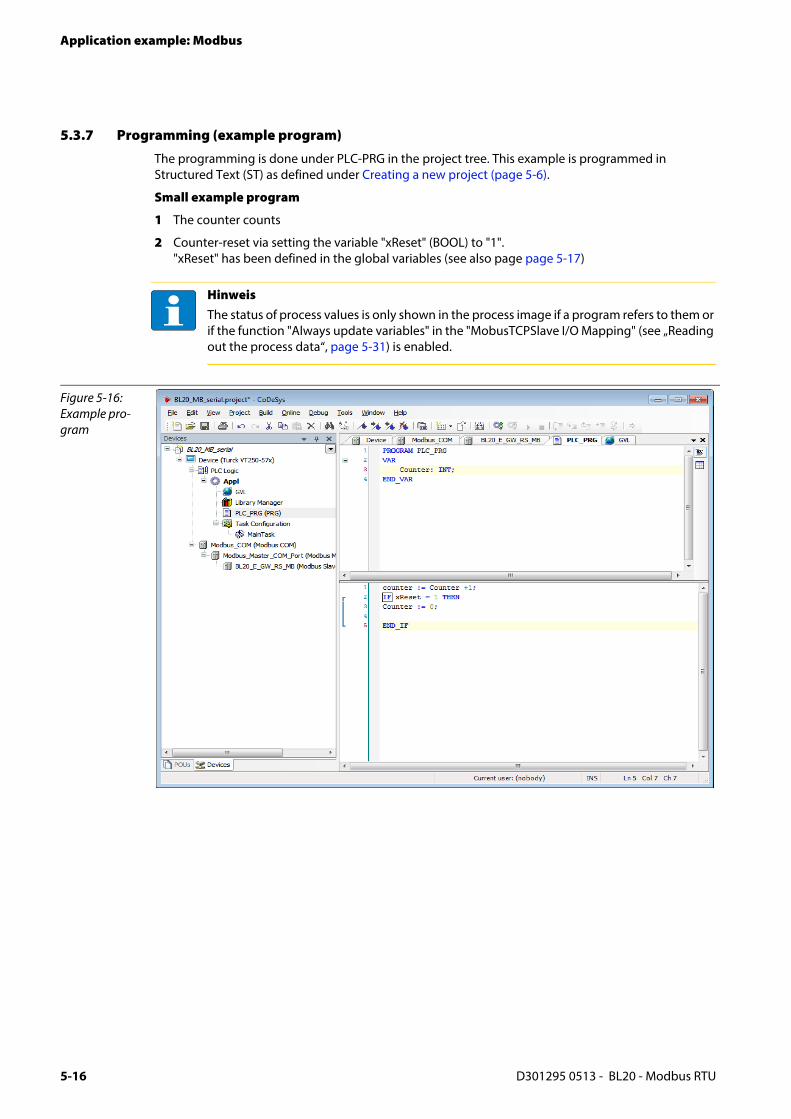
Application example: Modbus
5.3.7 Programming (example program)
The programming is done under PLC-PRG in the project tree. This example is programmed in Structured Text (ST) as defined under Creating a new project (page 5-6).
Small example program
1 The counter counts
2 Counter-reset via setting the variable "xReset" (BOOL) to "1". "xReset" has been defined in the global variables (see also page page 5-17)
HinweisThe status of process values is only shown in the process image if a program refers to them or if the function "Always update variables" in the "MobusTCPSlave I/O Mapping" (see „Reading out the process data“, page 5-31) is enabled.
Figure 5-16: Example pro-gram
D301295 0513 - BL20 - Modbus RTU5-16
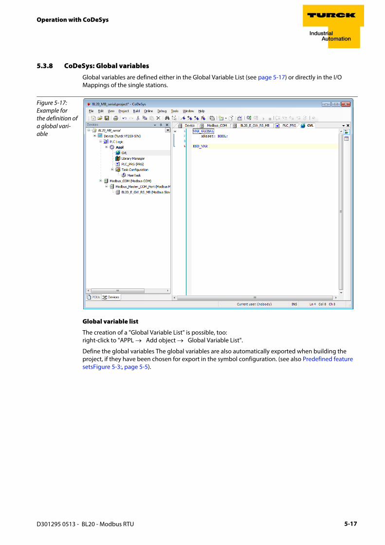
Operation with CoDeSys
5.3.8 CoDeSys: Global variables
Global variables are defined either in the Global Variable List (see page 5-17) or directly in the I/O Mappings of the single stations.
Global variable list
The creation of a "Global Variable List" is possible, too: right-click to "APPL → Add object → Global Variable List".
Define the global variables The global variables are also automatically exported when building the project, if they have been chosen for export in the symbol configuration. (see also Predefined feature setsFigure 5-3:, page 5-5).
Figure 5-17: Example for the definition of a global vari-able
D301295 0513 - BL20 - Modbus RTU 5-17

Application example: Modbus
5.3.9 Modbus channels
The communication between Modbus TCP master and Modbus slaves is realized through defined Modbus channels.
These channels are set in the register-tab "Modbus Slave Channel" using the "Add Channel..." button.
The process data of a slave can then be monitored under"ModbusTCPSlave I/O Mapping" (see 5.3.11, „Reading out the process data“, page 5-31)
The Modbus communication channels are defined by:
"Access Type": Modbus function code, which defines the access method (bit- or word wise, read or write).
"READ Register" or "WRITE Register" →"Offset": Specification of the start address for the Modbus Slave's register that has to be read or written. These specifications have to be taken from the slave's Modbus documentation!
Figure 5-18: Setting the Modbus chan-nels, examples
D301295 0513 - BL20 - Modbus RTU5-18

Operation with CoDeSys
Modbus data mapping
The mapping for the input and output data of a BL20-Modbus-station depends on it's configuration.
The TURCK-software "I/O-ASSISTANT (FDT/DTM" offer the possibility to create a Modbus-report for each Modbus-station, which shows the in-and output data mapping as well as the parameter- and diagnostic data mappings for the respective station.
Modbus mapping (I/O-ASSISTANT)
Figure 5-19: Modbus report - Mapping of in- and output data
MP
D301295 0513 - BL20 - Modbus RTU 5-19

Application example: Modbus
Figure 5-20: Modbus report - Mapping of parameter and diagnostic data
HinweisDetailed information about the modbus registers of the BL20-stations can be found in the descriptions in chapter 4.3.
D301295 0513 - BL20 - Modbus RTU5-20

Operation with CoDeSys
Setting the Modbus-channels (examples) and data mapping
1 Write:Writing of %QW0 and mapping of the counter value (VAR "Counter", see PLC_PRG, page 5-16) to the output byte of the station (%QW0).
1.1 Write: %QW0
– Access Type: Write Single Register (function code 06)
– Write Register, Offset:0x0800 (see below) The process output data of the station can be found in register 0×0800.
Figure 5-21: Mapping of out-put data acc. to Modbus-report
Figure 5-22: Modbus chan-nel, counter value, FC06
D301295 0513 - BL20 - Modbus RTU 5-21

Application example: Modbus
1.2 Mapping: counter value to %QW0
– The mapping of the counter value (VAR "Counter") to the station 's output register is done the the "ModbusTCPSlave I/O Mapping".Double click the field "variable" in the respective line. Use the "..."-button to open the dialog box "Input Assistant" .
– Select the variable to be mapped. As "Counter" been defined in PLC_PRG, see Programming (example program), it can be found there.
– Confirm with "OK". The counter value is now mirrored to %QW0 of the station and given out.
Figure 5-23: Mapping of the counter value to %QW0
D301295 0513 - BL20 - Modbus RTU5-22

Operation with CoDeSys
2 Read:
Bit 0 in register 0x0003 has to be read out(→ reset the counter (with „xReset“ = 1)
2.1 Read: %IW0
– Access Type: Read Holding Registers (function code 03)
– Read Register, Offset:0x0003 (see below)
Figure 5-24: Mapping of input data acc. to Modbus-report
D301295 0513 - BL20 - Modbus RTU 5-23
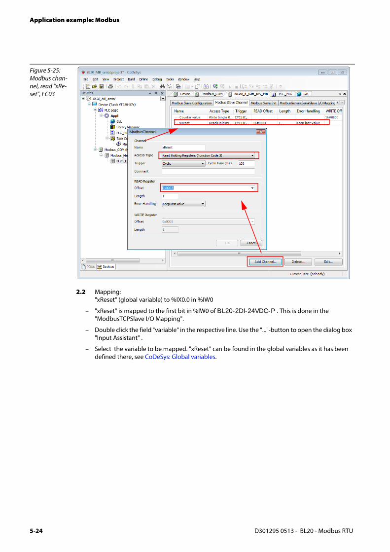
Application example: Modbus
2.2 Mapping: "xReset" (global variable) to %IX0.0 in %IW0
– "xReset" is mapped to the first bit in %IW0 of BL20-2DI-24VDC-P . This is done in the "ModbusTCPSlave I/O Mapping".
– Double click the field "variable" in the respective line. Use the "..."-button to open the dialog box "Input Assistant" .
– Select the variable to be mapped. "xReset" can be found in the global variables as it has been defined there, see CoDeSys: Global variables.
Figure 5-25: Modbus chan-nel, read "xRe-set", FC03
D301295 0513 - BL20 - Modbus RTU5-24

Operation with CoDeSys
– Confirm with "OK". A "1" at bit %IX0.0 will now reset the counter to zero.
Figure 5-26: Mapping of "xReset" to bit %IX0.0
D301295 0513 - BL20 - Modbus RTU 5-25
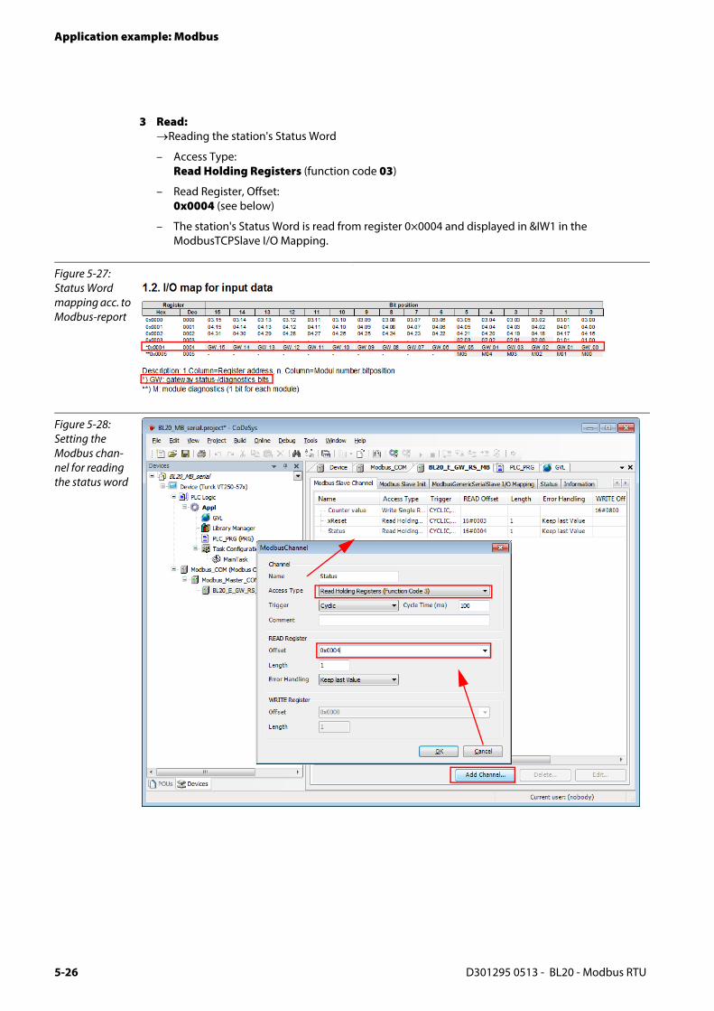
Application example: Modbus
3 Read: →Reading the station's Status Word
– Access Type: Read Holding Registers (function code 03)
– Read Register, Offset:0x0004 (see below)
– The station's Status Word is read from register 0×0004 and displayed in &IW1 in the ModbusTCPSlave I/O Mapping.
Figure 5-27: Status Word mapping acc. to Modbus-report
Figure 5-28: Setting the Modbus chan-nel for reading the status word
D301295 0513 - BL20 - Modbus RTU5-26

Operation with CoDeSys
Figure 5-29: Status Word in the process image
D301295 0513 - BL20 - Modbus RTU 5-27

Application example: Modbus
4 Write: Parameters of the station → Disable channel diagnosis at channel 1 at slot 3 of the station BL20-1AI-U(-10/0…+10VDC)
Writing parameters is normally done once during the program start and is thus not set as a "normal" Modbus channel under "ModbusSlave Channel", but as an Initialization channel under "Modbus Slave Init" (see Abbildung 6: Setting the initialization channel for the parameterization).
– Access Type: Write Single Register (function code 06)
– Write Register, Offset:0xB040 (see below)
The parameters of the station can be found in register 0xB040 to 0xB060.
Parameterization of the station
The example parameterization will be the disabling of the channel diagnosis at channel 1, slot 3 of the station (Register 0×B040, Bit 2).
The parameter register is build up as follows:
Figure 5-30: Assignment of parameter reg-isters
D301295 0513 - BL20 - Modbus RTU5-28

Operation with CoDeSys
A 22 = 4 will be written to register 0×B040, which results from the station's the parameter byte assignment.
Abbildung 6: Setting the ini-tialization chan-nel for the parameteriza-tion
D301295 0513 - BL20 - Modbus RTU 5-29

Application example: Modbus
5.3.10 Building, login and start
1 Building the program:
2 Login:
3 Start the program:
Figure 5-1: Building the program
Figure 5-2: Login
Figure 5-3: Starting the program
D301295 0513 - BL20 - Modbus RTU5-30

Operation with CoDeSys
5.3.11 Reading out the process data
The station's process data are shown in the register tab "ModbusGenericSerialSlaveSlave I/O Mapping".
HinweisIn order assure a regular updating of the process data, activate the function "Always update variables".
Figure 5-4: Modbus Slave I/O mapping with process data
D301295 0513 - BL20 - Modbus RTU 5-31

Application example: Modbus
5.3.12 Diagnosis evaluation
Evaluation of the Status word of the BL20-Station (%IW1)
Register 0x0004 contains the Status-word of the Station(see Modbus data mapping (page 5-19)).
According to the definition of the Modbus communication channel (see Setting the Modbus-channels (examples) and data mapping (page 5-21), it is read from %IW1 of the station image.
Figure 5-5: Status Word of the station
D301295 0513 - BL20 - Modbus RTU5-32

Operation with CoDeSys
the message is to be interpreted as follows:
Status-register → %IW 1, bit 0 = 1
→ status message: „DiagWarn“ = active diagnosis
at least one module at the gateway sends a diagnostic message (see also Register 0×100C: "Gateway status" (page 4-16)).
Evaluation of the group diagnosis
In order to identify the modules, which send diagnostic information, the group diagnosis register is read out. The group diagnosis register always follows the Status word of the gateway in the register mapping. Its position thus depends on the station configuration.
In this example, the group diagnosis register is register 0×0005. It contains on bit per module in the BL20-station, which displays whether the module sends diagnostic information or not.
The order of the bits in the registers corresponds to the order of the I/O-modules within the BL20-station.
Register Byte Bit 7 Bit 6 Bit 5 Bit 4 Bit 3 Bit 2 Bit 1 Bit 0
0x0004 0 UL low
- - - I/O CfgWarn.
- - DiagWarn
1 - FCE - MB Wdg
I/OCFG
I/OCOM
Usys low
Usys high
Abbildung 5-6: Group diagnosis register
D301295 0513 - BL20 - Modbus RTU 5-33

Application example: Modbus
According to the examples for setting the modbus channels (see Setting the Modbus-channels (examples) and data mapping (page 5-21)), the following channel is add to read out the group diagnosis register.
Read Holding Registers (FC3), register 0×0005, length 1
In the example, the group diagnosis is in %IW2:
→ bit 3 = 1
→ slot 4 sends diagnosis information
→ BL20-2AI-THERMO-PI (see also Used hard-/ software (page 5-2))
Abbildung 5-7: Channel for reading out the group diagnosis
Abbildung 5-8: group diagnosis
D301295 0513 - BL20 - Modbus RTU5-34

Operation with CoDeSys
Evaluation of the module diagnosis information
The diagnosis data of module BL20-2AI-THERMO-PI at slot 4 of the example station can be found in registers 0×A060 to 0×A07F (see also Modbus TCP-report (Figure 5-20: Modbus report - Mapping of parameter and diagnostic data (page 5-20)), whereby only register 0×A060 contains diagnosis information.
According to the examples for setting the modbus channels (see Setting the Modbus-channels (examples) and data mapping (page 5-21)), the following channel is add to read out the module diagnosis.
Read Holding Registers (FC3), register 0×A060, length 1:
%IW3 in the I/O image of the example station shows the diagnosis information available at slot4:
Abbildung 5-9: Diagnosis chan-nel
Abbildung 5-10: Diagnosis data at slot 4
D301295 0513 - BL20 - Modbus RTU 5-35

Application example: Modbus
Meaning:Bit 1: Open circuit at channel 1
(see also Diagnostic messages of the modules (page 4-45))
Abbildung 5-11: Mapping of diagnosis data according to Modbus report
D301295 0513 - BL20 - Modbus RTU5-36

D3
6 Guidelines for station planning
6.1 Module arrangement .................................................................................................................................... 2
6.1.1 Random module arrangement........................................................................................................................................................26.1.2 Complete planning..............................................................................................................................................................................36.1.3 Maximum system extension ............................................................................................................................................................3
6.2 Power supply ................................................................................................................................................. 6
6.2.1 Power supply to the gateway ..........................................................................................................................................................66.2.2 Module bus refreshing .......................................................................................................................................................................66.2.3 Creating potential groups.................................................................................................................................................................66.2.4 C-rail (cross connection) ....................................................................................................................................................................76.2.5 Direct wiring of relay modules ........................................................................................................................................................9
6.3 Protecting the service interface on the gateway...................................................................................... 10
6.4 Plugging and pulling electronics modules ............................................................................................... 10
6.5 Extending an existing station .................................................................................................................... 10
6.6 Firmware download .................................................................................................................................... 11
01295 0513 - BL20 - Modbus RTU 6-1
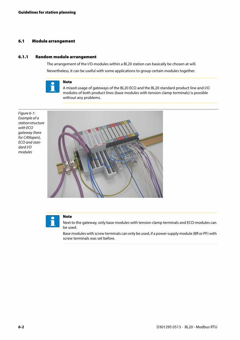
Guidelines for station planning
6.1 Module arrangement
6.1.1 Random module arrangement
The arrangement of the I/O-modules within a BL20 station can basically be chosen at will.
Nevertheless, it can be useful with some applications to group certain modules together.
NoteA mixed usage of gateways of the BL20 ECO and the BL20 standard product line and I/O modules of both product lines (base modules with tension clamp terminals) is possible without any problems.
Figure 6-1: Example of a station structure with ECO gateway (here for CANopen), ECO and stan-dard I/O modules
NoteNext to the gateway, only base modules with tension clamp terminals and ECO-modules can be used.
Base modules with screw terminals can only be used, if a power supply module (BR or PF) with screw terminals was set before.
D301295 0513 - BL20 - Modbus RTU6-2

Module arrangement
6.1.2 Complete planning
The planning of a BL20 station should be thorough to avoid faults and increase operating reliability.
The power to BL20 systems is supplied from a common external source. This avoids the occurrence of potential compensating currents within the BL20 station.
6.1.3 Maximum system extension
The maximum number of modules connected to the gateway BL20-E-GW-RS-MB/ET depends on the following:
The station extension may not exceed the maximum number of 32 modules.
Die maximum number of 192 communications bytes, which are transferred via the module bus from the gateway to the modules may not be exceeded (see below Table 6-1: Communication bytes and nominal current consumption of the BL20-modules).
If the maximum sum of the modules’ nominal current consumptions (see below Table 6-1: Communication bytes and nominal current consumption of the BL20-modules) right to the gateway (max. sum Σ IMB = 400 mA) is reached, a Bus Refreshing module has to be used in order to provide the module bus voltage. To the right of the Bus Refreshing module, the sum of the modules’ current consumptions can amount to 1,5 A.
For the calculation of the maximum system extension, the following table contains an overview about the modules’ nominal current consumptions.
AttentionIf there are more than two empty slots next to one another, the communication is interrupted to all following BL20 modules.
AttentionEnsure that a sufficient number of Bus Refreshing and Power Feeding modules are used if the system is extended to its maximum.
NoteIf the system limits are exceeded, the software I/O-ASSISTANT 3 (FDT/DTM) generates an error message when the user activates the command "Verify station".
Table 6-1: Communica-tion bytes and nominal current consumption of the BL20-modules
Module Communication bytes (on the module bus)
Nominal current consumption at the module bus
BL20-PF-24VDC-D 2 28 mA
BL20-PF-120/230VAC-D 2 25 mA
BL20-BR-24VDC-RED 1 -
D301295 0513 - BL20 - Modbus RTU 6-3

Guidelines for station planning
BL20-2DI-24VDC-P 1 28 mA
BL20-2DI-24VDC-N 1 28 mA
BL20-2DI-120/230VAC 1 28 mA
BL20-4DI-24VDC-P 1 29 mA
BL20-4DI-24VDC-N 1 28 mA
BL20-4DI-NAMUR 5 40 mA
BL20-E-8DI-24VDC-P 1 15 mA
BL20-E-16DI-24VDC-P 2 15 mA
BL20-16DI-24VDC-P 2 45 mA
BL20-32DI-24VDC-P 4 30 mA
BL20-1AI-I(0/4...20MA) 3 41 mA
BL20-2AI-I(0/4...20MA) 5 35 mA
BL20-1AI-U(-10/0...+10VDC) 3 41 mA
BL20-2AI-U(-10/0...+10VDC) 5 35 mA
BL20-2AI-PT/NI-2/3 5 45 mA
BL20-2AI-THERMO-PI 5 45 mA
BL20-4AI-U/I 9 30 mA
BL20-E-8AI-U/I-4AI-PT/NI 9 50 mA
BL20-2DO-24VDC-0.5A-P 2 32 mA
BL20-2DO-24VDC-0.5A-N 2 32 mA
BL20-2DO-24VDC-2A-P 2 33 mA
BL20-2DO-120/230VAC-0.5A 2 35 mA
BL20-4DO-24VDC-0.5A-P 2 30 mA
BL20-E-8DO-24VDC-0.5A-P 2 15 mA
BL20-E-16DO-24VDC-0.5A-P 2 25 mA
BL20-16DO-24VDC-0.5A-P 3 120 mA
BL20-32DO-24VDC-0.5A-P 5 30 mA
BL20-1AO-I(0/4...20MA) 4 39 mA
Table 6-1: Communica-tion bytes and nominal current consumption of the BL20-modules
Module Communication bytes (on the module bus)
Nominal current consumption at the module bus
D301295 0513 - BL20 - Modbus RTU6-4

Module arrangement
BL20-2AO-I(0/4...20MA) 7 40 mA
BL20-2AO-U(-10/0...+10VDC) 7 43 mA
BL20-E-4AO-U/I 9 50 mA
BL20-2DO-R-NC 1 28 mA
BL20-2DO-R-NO 1 28 mA
BL20-2DO-R-CO 1 28 mA
BL20-E-2CNT/2PWM 9 30 mA
BL20-1RS232 9 140 mA
BL20-1RS485/422 9 60 mA
BL20-1SSI 9 50 mA
BL20-2RFID-× 9 30 mA
BL20-E-1SWIRE 9 60 mA
Table 6-1: Communica-tion bytes and nominal current consumption of the BL20-modules
Module Communication bytes (on the module bus)
Nominal current consumption at the module bus
D301295 0513 - BL20 - Modbus RTU 6-5

Guidelines for station planning
6.2 Power supply
6.2.1 Power supply to the gateway
The gateway BL20-E-GW-RS-MB/ET offers an integrated power supply (see also Power supply, page 3-9).
6.2.2 Module bus refreshing
The number of BL20 modules, which can be supplied via the internal module bus by the gateway or a Bus Refreshing module depends on the modules’ nominal current consumptions at the module bus Table 6-1: Communication bytes and nominal current consumption of the BL20-modules, page 6-3).
With the system supply, it must be ensured that the same ground potential and ground connections are used. Compensating currents flow via the module bus if different ground potentials or ground connections are used, which can lead to the destruction of the Bus Refreshing module.
All Bus Refreshing modules are connected to one another via the same ground potential.
The power to the module bus is supplied via the connections 11 and 21 on the base module.
If the power supply from the module bus is not guaranteed, the software I/O-ASSISTANT 3 (FDT/DTM) generates an error message if the user activates the DTM "Additional functions → Verify station".
6.2.3 Creating potential groups
Power Feeding modules can be used to create potential groups. The potential isolation of potential groups to the left of the respective power distribution modules is provided by the base modules.
AttentionThe sum of the nominal current consumptions (seeTable 6-1: Communication bytes and nominal current consumption of the BL20-modules, page 6-3) of the used BL20 modules may not exceed 600 mA.If a Bus Refreshing module is mounted, the sum of the current consumptions which follow the Bus Refreshing module must not exceed 1,5 A.
NoteThe Bus Refreshing modules which are used in a station with BL20-E-GW-RS-MB/ET have to be combined with the base modules BL20-P3T-SBB-B or BL20-P4T-SBBC-B (tension clamp) or with the base modules BL20-P3S-SBB-B or BL20-P4S-SBBC-B (screw terminals).
NoteThe system can be supplied with power independent of the potential group formation.
D301295 0513 - BL20 - Modbus RTU6-6

Power supply
When using a digital input module for 120/230 V AC, it should be ensured that a potential group is created in conjunction with the Power Feeding module BL20-PF-120/230VAC-D.
6.2.4 C-rail (cross connection)
The C-rail runs through all base modules. The C-rail of the base modules for power distribution modules is mechanically separated; thus potentially isolating the adjoining supply groups.
Access to the C-rail is possible with the help of base modules with a C in their designation (for example, BL20-S4T-SBCS). The corresponding connection level is indicated on these modules by a thick black line. The black line is continuous on all I/O modules.
On power distribution modules, the black line is only above the connection 24. This makes clear that the C-rail is separated from the adjoining potential group to its left.
The C-rail can be used as required by the application, for example, as a protective earth (PE). In this case, the PE connection of each power distribution module must be connected to the mounting rail via an additional PE terminal, which is available as an accessory.
AttentionIt is not permitted to use modules with 24 V DC and 120/230 V AC field supply in a joint potential group.
Figure 6-2: C-rail (front view)
Figure 6-3: C-rail (side view)
WarningIt is permitted to load the C-rail with a maximum of 24 V. Not 230 V!
D301295 0513 - BL20 - Modbus RTU 6-7

Guidelines for station planning
The C-rail is not interrupted by the modules of the BL20-ECO-products. It is connected through the modules’ connection level. But, an access to the C-rail is not possible.
C-rails can be used for a common voltage supply (24 V DC) when relay modules are planned. To accomplish this, the load voltage is connected to a Power Feeding module with the BL20-P4x-SBBC base module. All the following relay modules are then supplied with power via the C-rail.
NoteFor information about introducing a BL20 station into a ground reference system, please read chapter 6.
Figure 6-4: Using the C-rail as a protective earth
AttentionWhen relay modules are planned and the C-rail is used for a common voltage supply, a further power distribution module must be used for the potential isolation to the following modules. The C-rail can only again be used as a PE following potential isolation.
23
22
21
13
12
11
23 23
22 22
21 21
13 13
12 12
11 11
23 2323
22 2222
21 2121
13 1313
12 1212
11 1111
24 24
23 23
22 22
21 21
14 14
13 13
12 12
11 11
24
23
22
21
14
13
12
11
2 DO
SBC
8 DI
ECO 2 DO
SBC
2 DI
SBB
PF
SBBC
2 DI2 DO
SBBCSBC
2 DO
SBC
2 DI
SBB
C-rail (PE)
PE
PF
12345678910111213141516
Unl
ock
end-
brac
ket b
efor
edis
mounting
Slid
eto
pco
ver
for
conf
igur
atio
nan
dse
rvic
e
Tx / A
Rx / B
GND
SHLD
!
GW
IOs
SERVICE
Tx
0 1
AD
DR
ES
S
20
21
22
23
24
RT
CFG
off on
RS232 RS485
Bps
Tx
Rx
UL
GNDL
USYS
GNDSYS
Tx / A
Rx / B
SBBC
C-rai (PE)
D301295 0513 - BL20 - Modbus RTU6-8

Power supply
Cross-connecting relay module roots is achieved by the use of jumpers. The corresponding wiring diagram including the jumpers can be found the manuals for BL20 I/O modules (German: D300716, English: D300717).
6.2.5 Direct wiring of relay modules
As well as the options mentioned above, relay modules can be wired directly. In this case, base modules without C-rail connections should be chosen to guarantee the potential isolation to the adjoining modules.
Figure 6-5: Using the C-rail as protective earth and for the power supply with relay modules
23
22
21
13
12
11
23 23
22 22
21 21
13 13
12 12
11 11
24
23
22
21
14
13
12
11
SBBC
2 DO
SBC
8 DI
ECO 2 DO
SBC
2 DI
SBB
C-rail (PE)
PE
PF
12345678910111213141516
24
23
22
21
14
13
12
11
24
23
22
21
14
13
12
11
24
23
22
21
14
13
12
11
24
23
22
21
14
13
12
11
24
23
22
21
14
13
12
11
PF NCNO
SBCSSBCS
NO
SBCS
NC
SBCS
C-rail (24 V DC)
SBBC
Unl
ock
end-
brac
ket b
efor
edis
mounting
Slid
eto
pco
ver
for
conf
igur
atio
nan
dse
rvic
e
Tx / A
Rx / B
GND
SHLD
!
GW
IOs
SERVICE
Tx
0 1
AD
DR
ES
S
20
21
22
23
24
RT
CFG
off on
RS232 RS485
Bps
Tx
Rx
UL
GNDL
USYS
GNDSYS
Tx / A
Rx / B
D301295 0513 - BL20 - Modbus RTU 6-9

Guidelines for station planning
6.3 Protecting the service interface on the gateway
During operation, the label protecting the service interface and the DIP-switches must remain in place due to EMC and ESD requirements.
6.4 Plugging and pulling electronics modules
BL20 enables the pulling and plugging of electronics modules without having to disconnect the field wiring. The BL20 station remains in operation if an electronics module is pulled. The voltage and current supplies as well as the protective earth connections are not interrupted
6.5 Extending an existing station
AttentionIf the field and system supplies remain connected when electronics modules are plugged or pulled, short interruptions to the module bus communications can occur in the BL20 station. This can lead to undefined statuses of individual inputs and outputs of different modules.
AttentionPlease note that extensions to the station (mounting further modules) should be carried out only when the station is in a voltage-free state.
D301295 0513 - BL20 - Modbus RTU6-10

Firmware download
6.6 Firmware download
Firmware can only be downloaded via the service interface on the gateway using the software toolI/O-ASSISTANT 3 (FDT/DTM).
More information is available in the program’s online help.
Attention- The station should be disconnected from the fieldbus when downloading.
- Firmware must be downloaded by authorized personnel only.
- The field level must be isolated.
D301295 0513 - BL20 - Modbus RTU 6-11

Guidelines for station planning
D301295 0513 - BL20 - Modbus RTU6-12

D3
7 Guidelines for electrical installation
7.1 General notes ................................................................................................................................................ 2
7.1.1 General.....................................................................................................................................................................................................27.1.2 Cable routing .........................................................................................................................................................................................2
– Cable routing inside and outside of cabinets ........................................................................................................................2– Cable routing outside buildings.................................................................................................................................................3
7.1.3 Lightning protection...........................................................................................................................................................................37.1.4 Transmission media.............................................................................................................................................................................3
7.2 Potential relationships ................................................................................................................................. 4
7.2.1 General.....................................................................................................................................................................................................4
7.3 Electromagnetic compatibility(EMC............................................................................................................ 5
7.3.1 Ensuring electromagnetic compatibility .....................................................................................................................................57.3.2 Grounding of inactive metal components..................................................................................................................................57.3.3 PE connection........................................................................................................................................................................................57.3.4 Earth-free operation............................................................................................................................................................................57.3.5 Mounting rails .......................................................................................................................................................................................6
7.4 Shielding of cables ........................................................................................................................................ 7
7.5 Potential compensation ............................................................................................................................... 8
7.5.1 Switching inductive loads.................................................................................................................................................................87.5.2 Protection against Electrostatic Discharge (ESD) .....................................................................................................................8
01295 0513 - BL20 - Modbus RTU 7-1

Guidelines for electrical installation
7.1 General notes
7.1.1 General
Cables should be grouped together, for example: signal cables, data cables, heavy current cables, power supply cables.
Heavy current cables and signal or data cables should always be routed in separate cable ducts or bundles. Signal and data cables must always be routed as close as possible to ground potential surfaces (for example support bars, cabinet sides etc.).
7.1.2 Cable routing
Correct cable routing prevents or suppresses the reciprocal influencing of parallel routed cables.
Cable routing inside and outside of cabinets
To ensure EMC-compatible cable routing, the cables should be grouped as follows:
Various types of cables within the groups can be routed together in bundles or in cable ducts.
Group 1:
shielded bus and data cables
shielded analog cables
unshielded cables for DC voltage ≤ 60 V
unshielded cables for AC voltage ≤ 25 V
Group 2:
unshielded cables for DC voltage > 60 V and ≤ 400 V
unshielded cables for AC voltage> 25 V and ≤ 400 V
Group 3:
unshielded cables for DC and AC voltages > 400 V
The following group combination can be routed only in separate bundles or separate cable ducts (no minimum distance apart):
Group 1/Group 2
The group combinations:
Group 1/Group 3 and Group 2/Group 3
must be routed in separate cable ducts with a minimum distance of 10 cm apart. This is equally valid for inside buildings as well as for inside and outside of switchgear cabinets.
D301295 0513 - BL20 - Modbus RTU7-2
General notes
Cable routing outside buildings
Outside of buildings, cables should be routed in closed (where possible), cage-type cable ducts made of metal. The cable duct joints must be electrically connected and the cable ducts must be earthed.
7.1.3 Lightning protection
The cables must be routed in double-grounded metal piping or in reinforced concrete cable ducts.
Signal cables must be protected against overvoltage by varistors or inert-gas filled overvoltage arrestors. Varistors and overvoltage arrestors must be installed at the point where the cables enter the building.
7.1.4 Transmission media
For a communication via Ethernet, different transmission media can be used:
coaxial cable 10Base2 (thin coax), 10Base5 (thick coax, yellow cable)
optical fiber (10BaseF)
twisted two-wire cable (10BaseT) with shielding (STP) or without shielding (UTP)
WarningObserve all valid guidelines concerning internal and external lightning protection and grounding specifications when routing cables outside of buildings.
NoteTURCK offers a variety of cable types for fieldbus lines as premoulded or bulk cables with different connectors.
The ordering information on the available cable types can be taken from the BL20-catalog.
D301295 0513 - BL20 - Modbus RTU 7-3

Guidelines for electrical installation
7.2 Potential relationships
7.2.1 General
The potential relationship of a Ethernet system realized with BL20 modules is characterized by the following:
The system supply of gateway and I/O-modules as well as the field supply are realized via one power feed at the gateway.
All BL20 modules (gateway, Power Feeding and I/O-modules), are connected capacitively via base modules to the mounting rails.
The block diagram shows the arrangement of a typical BL20 station with Ethernet gateway.
Figure 7-1: Block diagram of a BL20 station with Modbus- gateway
Module bus
Logik
Output
Logik
Input
5
24
UsysUL
Logik
Output
...
Bus
Refreshing
Gateway
...
UL
Logik
Output
...
Power
Feeding
CPU
5 V
24 V
Tx / A Usys
Service USB
UL
RS232/RS485
Rx / B
D301295 0513 - BL20 - Modbus RTU7-4

Electromagnetic compatibility(EMC
7.3 Electromagnetic compatibility(EMC
BL20 products comply in full with the requirements pertaining to EMC regulations. Nevertheless, an EMC plan should be made before installation.
Hereby, all potential electromechanical sources of interference should be considered such as galvanic, inductive and capacitive couplings as well as radiation couplings.
7.3.1 Ensuring electromagnetic compatibility
The EMC of BL20 modules is guaranteed when the following basic rules are adhered to:
Correct and large surface grounding of inactive metal components.
Correct shielding of cables and devices.
Proper cable routing – correct wiring.
Creation of a standard reference potential and grounding of all electrically operated devices.
Special EMC measures for special applications.
7.3.2 Grounding of inactive metal components
All inactive metal components (for example: switchgear cabinets, switchgear cabinet doors, supporting bars, mounting plates, tophat rails, etc.) must be connected to one another over a large surface area and with a low impedance (grounding). This guarantees a standardized reference potential area for all control elements and reduces the influence of coupled disturbances.
In the areas of screw connections, the painted, anodized or isolated metal components must be freed of the isolating layer. Protect the points of contact against rust.
Connect all free moving groundable components (cabinet doors, separate mounting plates, etc.) by using short bonding straps to large surface areas.
Avoid the use of aluminum components, as its quick oxidizing properties make it unsuitable for grounding.
7.3.3 PE connection
A central connection must be established between ground and PE connection (protective earth).
7.3.4 Earth-free operation
Observe all relevant safety regulations when operating an earthfree system.PE connection
WarningThe grounding must never – including cases of error – take on a dangerous touch potential. For this reason, always protect the ground potential with a protective cable.
D301295 0513 - BL20 - Modbus RTU 7-5

Guidelines for electrical installation
7.3.5 Mounting rails
All mounting rails must be mounted onto the mounting plate with a low impedance, over a large surface area, and must be correctly earthed. Use corrosion-resistant mounting rails
Mount the mounting rails over a large surface area and with a low impedance to the support system using screws or rivets.
Remove the isolating layer from all painted, anodized or isolated metal components at the connection point. Protect the connection point against corrosion (for example with grease; caution: use only suitable grease).
Figure 7-2: Mounting options
A TS 35B mounting railC mounting plate
D301295 0513 - BL20 - Modbus RTU7-6

Shielding of cables
7.4 Shielding of cables
Shielding is used to prevent interference from voltages and the radiation of interference fields by cables. Therefore, use only shielded cables with shielding braids made from good conducting materials (copper or aluminum) with a minimum degree of coverage of 80 %.
The cable shield should always be connected to both sides of the respective reference potential (if no exception is made, for example, such as high-resistant, symmetrical, analog signal cables). Only then can the cable shield attain the best results possible against electrical and magnetic fields.
A one-sided shield connection merely achieves an isolation against electrical fields.
The insulation of the shielded data-cable should be stripped and connected to the shield rail when the system is used in stationary operation The connection and securing of the shield should be made using metal shield clamps. The shield clamps must enclose the shielding braid and in so doing create a large surface contact area. The shield rail must have a low impedance (for example, fixing points of 10 to 20 cm apart) and be connected to a reference potential area.
The cable shield should not be severed, but routed further within the system (for example, to the switchgear cabinet), right up to the interface connection.
AttentionWhen installing, please pay attention to the following...
- the shield should be connected immediately when entering the system,
- the shield connection to the shield rail should be of low impedance,
- the stripped cable-ends are to be kept as short as possible,
- the cable shield is not to be used as a bonding conductor.
NoteShould it not be possible to ground the shield on both sides due to switching arrangements or device specific reasons, then it is possible to route the second cable shield side to the local reference potential via a capacitor (short connection distances). If necessary, a varistor or resistor can be connected parallel to the capacitor, to prevent disruptive discharges when interference pulses occur.
NoteA further possibility is a double-shielded cable (galvanically separated), whereby the innermost shield is connected on one side and the outermost shield is connected on both sides.
D301295 0513 - BL20 - Modbus RTU 7-7

Guidelines for electrical installation
7.5 Potential compensation
Potential differences can occur between installation components that are in separate areas if these
are fed by different supplies,
have double-sided conductor shields which are grounded on different installation components.
A potential-compensation cable must be routed to the potential compensation.
A potential compensation cable must have the following characteristics:
Low impedance. In the case of compensation cables that are routed on both sides, the compensation line impedance must be considerably smaller than that of the shield connection (max. 10 % of shield connection impedance).
Should the length of the compensation cable be less than 200 m, then its cross-section must be at least 16 mm2 /0.025 inch2. If the cable length is greater than 200 m, then a cross-section of at least 25 mm2 / 0.039 inch2 is required.
The compensation cable must be made of copper or zinc coated steel.
The compensation cable must be connected to the protective conductor over a large surface area and must be protected against corrosion.
Compensation cables and data cables should be routed as close together as possible, meaning the enclosed area should be kept as small as possible.
7.5.1 Switching inductive loads
In the case of inductive loads, a protective circuit on the load is recommended.
7.5.2 Protection against Electrostatic Discharge (ESD)
WarningNever use the shield as a potential compensation.
AttentionElectronic modules and base modules are at risk from electrostatic discharge when disassembled. Avoid touching the bus connections with bare fingers as this can lead to ESD damage.
D301295 0513 - BL20 - Modbus RTU7-8

D3
8 BL20-Approvals for Zone 2/ Division 2
NoteThe Zone 2 - approval certificates for BL20 can be found in a separate manual for approvals D301255 atwww.turck.de.
01295 0513 - BL20 - Modbus RTU 8-1

BL20-Approvals for Zone 2/ Division 2
D301295 0513 - BL20 - Modbus RTU8-2

D3
9 Appendix
9.1 Data image of the technology modules ...................................................................................................... 2
9.1.1 1RS232/ 1RS485-module...................................................................................................................................................................2– Process input data ...........................................................................................................................................................................2– Process output data ........................................................................................................................................................................4
9.1.2 SSI module..............................................................................................................................................................................................6– Process input data ...........................................................................................................................................................................6– Process output data ..................................................................................................................................................................... 11
9.1.3 SWIRE-module.................................................................................................................................................................................... 13– SWIRE in Modbus .......................................................................................................................................................................... 13– Process input data ....................................................................................................................................................................... 13– Process output data .................................................................................................................................................................... 14
9.1.4 Encoder/PWM-moduleBL20-E-2CNT-2PWM ........................................................................................................................... 159.1.5 RFID-module BL20-2RFID-S/ -A.................................................................................................................................................... 15
9.2 Ident codes the BL20-modules.................................................................................................................. 16
01295 0513 - BL20 - Modbus RTU 9-1

Appendix
9.1 Data image of the technology modules
9.1.1 1RS232/ 1RS485-module
Process input data
Process input data is data from the connected field device that is transmitted via the BL××-1RS×××-module to the PLC. The BL××-1RS×××-module sends the data, received by the device, into a 128-byte receive-buffer. The module then transmits the data segmented via the module bus and the gateway to the PLC.
The transmission is realized in a 8-byte format which is structured as follows:
1 status byte is required to ensure trouble-free transmission of the data.
1 byte contains the diagnostics data.
6 bytes are used to contain the user data.
Figure 9-1: Process input data of RS××× modules
D301295 0513 - BL20 - Modbus RTU9-2
Data image of the technology modules
Table 9-1: Meaning of the data bits (process input)
Designation Value
Description
BufOvfl; FrameErr; HndShErr; HwFailure; PrmErr
0 - 255
Diagnostic information (correspond to the diagnostic information in the diagnosis telegram). These diagnostics are always displayed and independent to the setting of the parameter "Diagnostics".
STAT 0-1 1: The communication with the data terminal equipment (DTE) is not disturbed.0: The communication with the data terminal equipment (DTE) is disturbed. A diagnosis message is generated if the parameter "Diagnostics" is set to "0" = release. The diagnostic data show the cause of the communication disturbance. The user has to set back this bit in the process output data by using STATRES.
TX_CNT_ACK 0-3 The value TX_CNT_ACK is a copy of the value TX_CNT. The value TX_CNT was transferred together with the last data segment of the process output data.The value TX_CNT_ACK is a confirmation of successful acceptance of the data segment using TX_CNT.
RX_CNT 0-3 This value is transferred together with every data segment. The RX_CNT values are sequential: The RX_CNT values are sequential: 00->01->10->11->00… (decimal: 0->1->2->3->0…)Errors in this sequence show the loss of data segments.
RX_BYTE_CNT 0-7 Number of the valid bytes in this data segment.
D301295 0513 - BL20 - Modbus RTU 9-3

Appendix
Process output data
Process output data are data which are sent from the PLC via the gateway and the BL××-1RS×××-module to a connected field device.
The data received from the PLC are loaded into the 64-bit transmit-buffer in the BL××-1RS×××-module.
The transmission is realized in a 8-byte format which is structured as follows:
1 control byte is required to ensure trouble-free transmission of the data.
1 byte contains, signals to start the flushing of transmit- and receive buffer.
6 bytes are used to contain the user data.
Figure 9-2: Process output data of RS×××-modules
Table 9-2: Meaning of the data bits (process output)
Designation Value
Description
STATRES 0-1 This bit is set to reset the STAT bit in the process input data.With the change from 1 to 0 the STAT bit is reset (from 0 to 1). If this bit is 0, all changes in TX_BYTE_CNT, TX_CNT and RX_CNT_ACK are ignored. The clearing of the receive and transmit buffer by RXBUF FLUSH/TXBUF FLUSH is possible.The value 1 or the transition from 0 to 1 disables the clearing of the receive and transmit buffer by the RXBUF FLUSH/TXBUF FLUSH.
D301295 0513 - BL20 - Modbus RTU9-4

Data image of the technology modules
RXBUF FLUSH 0 - 1 The RXBUF FLUSH bit is used for clearing the receive buffer.If STATRES = 1:A request with RXBUF FLUSH = 1 will be ignored.If STATRES = 0:RXBUF FLUSH = 1 will clear the receive buffer.
TXBUF FLUSH 0-1 The TXBUF FLUSH bit is used for clearing the transmit buffer.If STATRES = 1:A request with TXBUF FLUSH = 1 will be ignored.If STATRES = 0:TXBUF FLUSH = 1 will clear the receive buffer.
RX_CNT_ACK 0-3 The value RX_CNT_ACK is a copy of the value RX_CNT. The value TX_CNT was transferred together with the last data segment of the process output data.RX_CNT_ACK has to be set analog to RX_CNT (in the status byte). RX_CNT_ACK is an acknowledge for the successful transmission of the data segment with RX_CNT. New data can now be received.
TX_CNT 0-3 This value is transferred together with every data segment. The TX_CNT values are sequential: The TX_CNT values are sequential: 00->01->10->11->00… (decimal: 0->1->2->3->0…)Errors in this sequence show the loss of data segments.
TX_BYTE_CNT 0 - 7 Number of the valid bytes in this data segment.
Table 9-2: Meaning of the data bits (process output)
Designation Value
Description
D301295 0513 - BL20 - Modbus RTU 9-5
Appendix
9.1.2 SSI module
Process input data
The field input data is transferred from the connected field device to BL20-1SSI-module.
The process input data is the data that is transferred by the BL20-1SSI-module via a gateway to the PLC.
The transmission is realized in a 8-byte format which is structured as follows:
4 bytes are used for representing the data that was read from the register with the address stated at REG_RD_ADR.
When necessary, 1 byte represents the register address of the read data and an acknowledgement that the read operation was successful.
1 byte can be used to transfer status messages of the SSI encoder. This byte also contains an acknowledgement that the write operation to the register was successful and indication of an active write operation.
1 byte contains the results of comparison operations with the SSI encoder value.
1 byte contains messages concerning the communication status between the BL20-1SSI module and the SSI encoder, as well as other results of comparison operations.
The following table describes the structure of the 8 x 8 bits of the process input data.
STS (or ERR) contains non-retentive status information, i.e. the bit concerned indicates the actual status.
FLAG describes a retentive flag that is set in the event of a particular event. The bit concerned retains the value until it is reset.
D301295 0513 - BL20 - Modbus RTU9-6
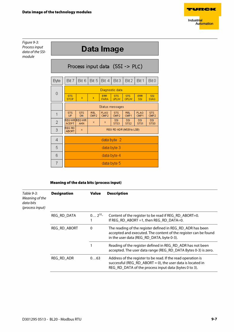
Data image of the technology modules
Meaning of the data bits (process input)
Figure 9-3: Process input data of the SSI-module
Table 9-3: Meaning of the data bits (process input)
Designation Value Description
REG_RD_DATA 0… 232-1
Content of the register to be read if REG_RD_ABORT=0. If REG_RD_ABORT =1, then REG_RD_DATA=0.
REG_RD_ABORT 0 The reading of the register defined in REG_RD_ADR has been accepted and executed. The content of the register can be found in the user data (REG_RD_DATA, byte 0-3).
1 Reading of the register defined in REG_RD_ADR has not been accepted. The user data range (REG_RD_DATA Bytes 0-3) is zero.
REG_RD_ADR 0…63 Address of the register to be read. If the read operation is successful (REG_RD_ABORT = 0), the user data is located in REG_RD_DATA of the process input data (bytes 0 to 3).
D301295 0513 - BL20 - Modbus RTU 9-7

Appendix
REG_WR_ACEPT 0 Writing the user data from the process output to the register addressed with REG_WR_ADR in the process output could not be done.
1 Writing the user data from the process output to the register addressed with REG_WR_ADR in the process output was successful.
REG_WR_AKN 0 No modification of the data in the register bank by process output, i.e. REG_WR = 0. A write job would be accepted with the next telegram of process output data.(handshake for data transmission to the register.)
1 A modification of the register contents by a process output was initiated, which means REG_WR = 1.A write job would not be accepted with the next telegram of process output data.
SSI_STS3 0 These four bits transfer the status bits of the SSI encoder with the status messages of the SSI module. With some SSI encoders, the status bits are transferred together with the position value.1
SSI_STS2 0
1
SSI_STS1 0
1
SSI_STS0 0
1
STS_UP (LED UP) 0 The SSI encoder values are decremented or the values are constant.
1 The SSI encoder values are incremented.
STS_DN(LED DN)
0 The SSI encoder values are incremented or the values are constant.
1 The SSI encoder values are decremented.
REL_CMP2 0 A comparison of the register contents has produced the following result:(REG_SSI_POS) < (REG_CMP2)
1 A comparison of the register contents has produced the following result:(REG_SSI_POS) ≥ (REG_CMP2)
Table 9-3: Meaning of the data bits (process input)
Designation Value Description
D301295 0513 - BL20 - Modbus RTU9-8
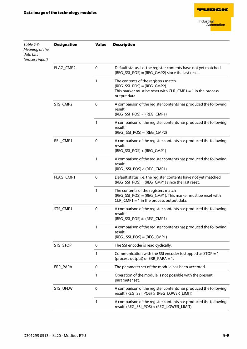
Data image of the technology modules
FLAG_CMP2 0 Default status, i.e. the register contents have not yet matched (REG_SSI_POS) = (REG_CMP2) since the last reset.
1 The contents of the registers match(REG_SSI_POS) = (REG_CMP2).This marker must be reset with CLR_CMP1 = 1 in the process output data.
STS_CMP2 0 A comparison of the register contents has produced the following result: (REG_SSI_POS) ≠ (REG_CMP1)
1 A comparison of the register contents has produced the following result: (REG_ SSI_POS) = (REG_CMP2)
REL_CMP1 0 A comparison of the register contents has produced the following result:(REG_SSI_POS) < (REG_CMP1)
1 A comparison of the register contents has produced the following result:(REG_ SSI_POS) ≥ (REG_CMP1)
FLAG_CMP1 0 Default status, i.e. the register contents have not yet matched (REG_SSI_POS) = (REG_CMP1) since the last reset.
1 The contents of the registers match (REG_SSI_POS) = (REG_CMP1). This marker must be reset with CLR_CMP1 = 1 in the process output data.
STS_CMP1 0 A comparison of the register contents has produced the following result: (REG_SSI_POS) ≠ (REG_CMP1)
1 A comparison of the register contents has produced the following result:(REG_ SSI_POS) = (REG_CMP1)
STS_STOP 0 The SSI encoder is read cyclically.
1 Communication with the SSI encoder is stopped as STOP = 1 (process output) or ERR_PARA = 1.
ERR_PARA 0 The parameter set of the module has been accepted.
1 Operation of the module is not possible with the present parameter set.
STS_UFLW 0 A comparison of the register contents has produced the following result: (REG_SSI_POS) ≥ (REG_LOWER_LIMIT)
1 A comparison of the register contents has produced the following result: (REG_SSI_POS) < (REG_LOWER_LIMIT)
Table 9-3: Meaning of the data bits (process input)
Designation Value Description
D301295 0513 - BL20 - Modbus RTU 9-9

Appendix
STS_OFLW 0 A comparison of the register contents has produced the following result: (REG_SSI_POS) ≤ (REG_UPPER_LIMIT)
1 A comparison of the register contents has produced the following result: (REG_SSI_POS) > (REG_UPPER_LIMIT)
ERR_SSI 0 SSI encoder signal present.
1 SSI encoder signal faulty. (e.g. due to a cable break).
SSI_DIAG 0 No enabled status signal is active (SSI_STSx = 0).
1 At least one enabled status signal is active (SSI_STSx = 1)
Table 9-3: Meaning of the data bits (process input)
Designation Value Description
D301295 0513 - BL20 - Modbus RTU9-10

Data image of the technology modules
Process output data
Field output data is output from an BL20-1SSI-module to a field device.
The process output data is the data that is transferred by the PLC via a gateway to the BL20-1SSI module.
The transmission is realized in a 8-byte format which is structured as follows:
1 byte contains a Stop bit for interrupting communication with the encoder.
1 byte is used for controlling the comparison operations.
1 byte contains the register address of the data to be written to bytes 0 to 3 of this telegram and a write request.
1 byte contains the register address for the data that is to be read with the next response telegram.
4 bytes are used for representing the data that is to be written to the register with the address specified at REG_WR_DATA.
Figure 9-4: Process output data of the SSI-module
D301295 0513 - BL20 - Modbus RTU 9-11

Appendix
Meaning of the data bits (process output)
Table 9-4: Meaning of the data bits (process output)
Designation Value Description
REG_WR_DATA 0… 232-1 Value which has to be written to the register with the address REG_WR_ADR.
REG_RD_ADR 0…63 Address of the register which has to be read. If the reading was successful (REG_RD_ABORT = 0), the user data can be found in REG_RD_DATA in the status interface (bytes 4-7).
REG_WR 0 Default status, i.e. there is no request to overwrite the content of the register with the address stated at REG_WR_ADR with REG_WR_DATA. Bit REG_WR_AKN is reset (0) if necessary.
1 Request to overwrite the content of the register with address REG_WR_ADR with REG_WR_DATA.
REG_WR_ADR 0…63 Address of the register, which has to be written with REG_WR_DATA.
CLR_CMP2 0 Default status, i.e. no reset of FLAG_CMP2 active.
1 Reset of FLAG_CMP2 active.
EN_CMP2 0 Default status, i.e. the data bits REL_CMP2, STS_CMP2 and FLAG_CMP2 always have the value 0, irrespective of the actual SSI encoder value.
1 Comparison active, i.e. the data bits REL_CMP2, STS_CMP2 and FLAG_CMP2 always have a value based on the result of the comparison with the SSI encoder value.
CLR_CMP1 0 Default status, i.e. reset of FLAG_CMP1 not active.
1 Reset of FLAG_CMP1 active.
EN_CMP1 0 Default status, i.e. the data bits REL_CMP1, STS_CMP1 and FLAG_CMP1 always have the value 0, irrespective of the actual SSI encoder value.
1 Comparison active, i.e. the data bits REL_CMP1, STS_CMP1 and FLAG_CMP1 always have a value based on the result of the comparison with the SSI encoder value.
STOP 0 Request to read the SSI encoder cyclically
1 Request to interrupt communication with the encoder
D301295 0513 - BL20 - Modbus RTU9-12
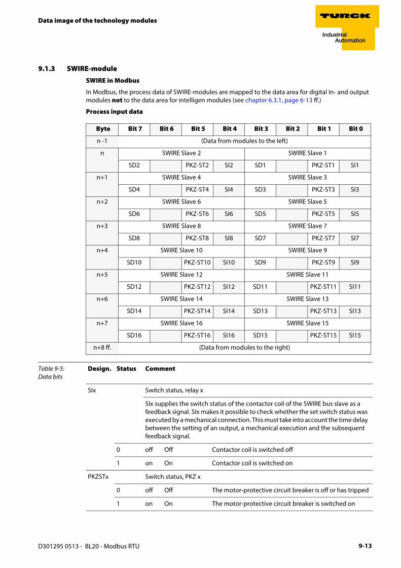
Data image of the technology modules
9.1.3 SWIRE-module
SWIRE in Modbus
In Modbus, the process data of SWIRE-modules are mapped to the data area for digital In- and output modules not to the data area for intelligen modules (see chapter 6.3.1, page 6-13 ff.)
Process input data
Byte Bit 7 Bit 6 Bit 5 Bit 4 Bit 3 Bit 2 Bit 1 Bit 0
n -1 (Data from modules to the left)
n SWIRE Slave 2 SWIRE Slave 1
SD2 PKZ-ST2 SI2 SD1 PKZ-ST1 SI1
n+1 SWIRE Slave 4 SWIRE Slave 3
SD4 PKZ-ST4 SI4 SD3 PKZ-ST3 SI3
n+2 SWIRE Slave 6 SWIRE Slave 5
SD6 PKZ-ST6 SI6 SD5 PKZ-ST5 SI5
n+3 SWIRE Slave 8 SWIRE Slave 7
SD8 PKZ-ST8 SI8 SD7 PKZ-ST7 SI7
n+4 SWIRE Slave 10 SWIRE Slave 9
SD10 PKZ-ST10 SI10 SD9 PKZ-ST9 SI9
n+5 SWIRE Slave 12 SWIRE Slave 11
SD12 PKZ-ST12 SI12 SD11 PKZ-ST11 SI11
n+6 SWIRE Slave 14 SWIRE Slave 13
SD14 PKZ-ST14 SI14 SD13 PKZ-ST13 SI13
n+7 SWIRE Slave 16 SWIRE Slave 15
SD16 PKZ-ST16 SI16 SD15 PKZ-ST15 SI15
n+8 ff. (Data from modules to the right)
Table 9-5: Data bits
Design. Status Comment
SIx Switch status, relay x
SIx supplies the switch status of the contactor coil of the SWIRE bus slave as a feedback signal. SIx makes it possible to check whether the set switch status was executed by a mechanical connection. This must take into account the time delay between the setting of an output, a mechanical execution and the subsequent feedback signal.
0 off Off Contactor coil is switched off
1 on On Contactor coil is switched on
PKZSTx Switch status, PKZ x
0 off Off The motor-protective circuit breaker is off or has tripped
1 on On The motor-protective circuit breaker is switched on
D301295 0513 - BL20 - Modbus RTU 9-13

Appendix
Process output data
SCx Communication error, slave x
Setting the parameter SCDIAGSx sets the SCx-bit in the process input data. The information is provided as status information in the PLC for the user.
0 ON LINE
ON LINE Status of slave x:
1 OFF LINE
OFF LINE Status of slave x: diagnostics available
Byte Bit 7 Bit 6 Bit 5 Bit 4 Bit 3 Bit 2 Bit 1 Bit 0
n -1 (Data from modules to the left)
n SWIRE Slave 2 SWIRE Slave 1
SO2 SO1
n+1 SWIRE Slave 4 SWIRE Slave 3
SO4 SO3
n+2 SWIRE Slave 6 SWIRE Slave 5
SO6 SO5
n+3 SWIRE Slave 8 SWIRE Slave 7
SO8 SO7
n+4 SWIRE Slave 10 SWIRE Slave 9
SO10 SO9
n+5 SWIRE Slave 12 SWIRE Slave 11
SO12 SO11
n+6 SWIRE Slave 14 SWIRE Slave 13
SO14 SO13
n+7 SWIRE Slave 16 SWIRE Slave 15
SO16 SO15
n+8 ff. (Data from modules to the right)
Table 9-6: Data bits
Design. Status Comment
SOx relay x
SOx is transferred as the switch status of the contactor coil from the SWIRE bus master to the appropriate SWIRE bus slave.
0 off Off Contactor not switched on
1 on On Contactor switched on
Table 9-5: Data bits
Design. Status Comment
D301295 0513 - BL20 - Modbus RTU9-14

Data image of the technology modules
9.1.4 Encoder/PWM-module: BL20-E-2CNT-2PWM
Detailed information about the process image of the module can be found in separate manual, D301224, "BL20 – I/O-MODULES BL20-E-2CNT-2PWM", chapter 2)
9.1.5 RFID-module: BL20-2RFID-S
BL20-2RFID-S (see RFID-documentation under www.turck.de)
D301295 0513 - BL20 - Modbus RTU 9-15

Appendix
9.2 Ident codes the BL20-modules
Each module is identified by the gateway using a unique identifier.
Table 9-7: Moduleident codes
Module ident code
Digital input modules
BL20-2DI-24VDC-P 0x210020xx
BL20-2DI-24VDC-N 0x220020xx
BL20-2DI-120/230VAC 0x230020xx
BL20-4DI-24VDC-P 0x410030xx
BL20-4DI-24VDC-N 0x420030xx
BL20-4DI-NAMUR 0x015640xx
BL20-E-8DI-24VDC-P 0x610040xx
BL20-16DI-24VDC-P 0x810050xx
BL20-E-16DI-24VDC-P 0x820050xx
BL20-32DI-24VDC-P 0xA10070xx
Analog input modules
BL20-1AI-I(0/4…20MA) 0x012350xx
BL20-2AI-I(0/4…20MA) 0x225570xx
BL20-1AI-U(-10/0…+10VDC) 0x011350xx
BL20-2AI-U(-10/0…+10VDC) 0x235570xx
BL20-2AI-PT/NI-2/3 0x215770xx
BL20-2AI-THERMO-PI 0x215570xx
BL20-2AIH-I 0x2179C0xx
BL20-4AI-U/I 0x417790xx
BL20-E-4AI-TC 0x427790xx
BL20-E-8AI-U/I-4AI-PT/NI 0x6199B0xx
Digital output modules
BL20-2DO-24VDC-0,5A-P 0x212002××
BL20-2DO-24VDC-0,5A-N 0x222002××
BL20-2DO-24VDC-2A-P 0x232002××
BL20-2DO-120/230VAC-0.5A 0x250002××
BL20-4DO-24VDC-0,5A-P 0x013003××
BL20-E-8DO-24VDC-0.5A-P 0x610004××
D301295 0513 - BL20 - Modbus RTU9-16

Ident codes the BL20-modules
BL20-16DO-24VDC-0,5A-P 0x413005××
BL20-E-16DO-24VDC-0.5A-P 0x820005××
BL20-32DO-24VDC-0,5A-P 0x614007××
Analog output modules
BL20-1AO-I(0/4…20MA) 0x010605××
BL20-2AO-I(0/4…20MA) 0x220807××
BL20-2AO-U(-10/0…+10VDC) 0x210807××
BL20-2AO-H 0x217AB7××
BL20-E-4AO-U/I 0x417A09××
Relay modules
BL20-2DO-R-NC 0x230002××
BL20-2DO-R-NO 0x220002××
BL20-2DO-R-CO 0x210002××
technology modules
BL20-1RS232 0x014799××
BL20-1RS485/422 0x024799××
BL20-1SSI 0x044799××
BL20-E-1SWIRE 0x169C99××
BL20-E-2CNT-2PWM 0x017BCCxx
BL20-2RFID-S 0x2179CC××
Power distribution modules
BL20-BR-24VDC-D 0x013000xx
BL20-BR-24VDC-RED 0x440030xx
BL20-PF-24VDC-D 0x023000xx
BL20-PF-120/230VAC-D 0x053000xx
Table 9-7: Moduleident codes
Module ident code
D301295 0513 - BL20 - Modbus RTU 9-17

Appendix
D301295 0513 - BL20 - Modbus RTU9-18

10 Index
Aaddress assignment ..................................................... 3-12auxiliary power supply ................................................... 3-5
Bbase modules ................................................................. 2-7basic concept ................................................................. 2-2BL20 components .......................................................... 2-3block diagram, station ................................................... 7-4bus terminating resistor ............................................... 3-15
Ccable routing .................................................................. 7-2cable shield ..................................................................... 7-7CoDeSys .......................................................................... 5-2–communication path ................................................... 5-9–communication settings .............................................. 5-8–Ethernet-adapter ....................................................... 5-10–Ethernet-master ......................................................... 5-10–feature sets ................................................................... 5-5–Global variable list ..................................................... 5-17–localhost ....................................................................... 5-8–Modbus master .......................................................... 5-12–PLC_PRG ..................................................................... 5-16C-rail (cross connection) ................................................ 6-7
Ddiagnostic messages, modules .................................... 4-45Division 2 ........................................................................ 8-1
Eearth-free operation ....................................................... 7-5electrical installation ...................................................... 7-2electrostatic discharge ................................................... 7-8EMC ................................................................................. 7-5end bracket .................................................................... 2-8end plate ........................................................................ 2-8
Ffirmware download ...................................................... 6-11flexibility ......................................................................... 2-2
Ggateway–address assignment ................................................... 3-12–block diagram .............................................................. 3-4–configuration via DIP-switches ................................. 3-12–diagnostic messages ................................................. 3-18–function ........................................................................ 3-3–LEDs ............................................................................ 3-18–service-interface ......................................................... 3-11–status indicators ......................................................... 3-18–technical data ............................................................... 3-4
Hhandling ......................................................................... 2-2
Hardware ........................................................................ 5-2
Iinductive loads, protective circuit ................................. 7-8
Llightning protection ....................................................... 7-3
Mmaintenance ................................................................... 1-4Modbus–registers ........................................................................ 4-4module arrangement ..................................................... 6-2module order .................................................................. 6-2mounting rail .................................................................. 7-6
Ooperation, safe ................................................................ 1-4operation, trouble-free ................................................... 1-4outputs, error behavior ................................................ 4-20
Pparameters, modules .................................................... 4-21PE connection ................................................................. 7-5potential compensation ................................................. 7-8potential compensation cable ....................................... 7-8potential groups ............................................................. 6-6potential relationships ................................................... 7-4prescribed use ................................................................ 1-4process input–RS××× ........................................................................... 9-2–SSI .................................................................................. 9-6–SWIRE .......................................................................... 9-13process output–RS××× ........................................................................... 9-4–SSI ................................................................................ 9-11–SWIRE .......................................................................... 9-14product overview ........................................................... 2-1
Sshield ............................................................................... 7-7shield connection–(gateway) .................................................................... 2-10Software .......................................................................... 5-2storage ............................................................................ 1-4supply voltage ................................................................ 3-5symbols ........................................................................... 1-3
Ttransmission media ........................................................ 7-3transport ......................................................................... 1-4transport, appropriate .................................................... 1-4
Uuse, prescribed ................................................................ 1-4
D301295 0513 - BL20 - Modbus RTU 10-1

Index
ZZone 2 ............................................................................. 8-1
D301295 0513 - BL20 - Modbus RTU10-2

D30
1295
051
3
Hans Turck GmbH & Co. KG45472 Mülheim an der Ruhr GermanyWitzlebenstraße 7Tel. +49 (0) 208 4952-0Fax +49 (0) 208 4952-264E-Mail [email protected] www.turck.com
www.turck.com