Embed Size (px)
Citation preview

Technical Manual NAM-BL4x-MT-EN-C The information in this document is the property of Automatic Systems and is confidential. The consignee withholds from using it for anything other than the use of the products or the execution of the project to which they belong and withholds from communicating it to third parties without prior written agreement from Automatic Systems. Document subject to change without prior notice.
BL 4x
Technical manual
BL40 BL41
BL43 BL46

p 2/58
Technical Manual NAM-BL4x-MT-EN-C The information in this document is the property of Automatic Systems and is confidential. The consignee withholds from using it for anything other than the use of the products or the execution of the project to which they belong and withholds from communicating it to third parties without prior written agreement from Automatic Systems. Document subject to change without prior notice.
Document revisions
Revision no.
Date Written by
Checked by Subject
A 2011-09-22 SSA First edition
B 2012-05-09 SSA - SR barrier type added (all through manual)
- Speed controller adjustment procedure updated (CH 5.1)
- Spring adjustment table updated (CH 5.2)
- Wiring diagram updated (CH 9)
C 2013-02-08 JPS SSA - Component list (CH 2.1)
- Operating Principle (CH 2.2)
- Mechanical locking of the arm (CH 2.3)
- Positionning of the equipment (CH 4.2)
- Wiring diagram updated (CH 9)

p 3/58
Technical Manual NAM-BL4x-MT-EN-C The information in this document is the property of Automatic Systems and is confidential. The consignee withholds from using it for anything other than the use of the products or the execution of the project to which they belong and withholds from communicating it to third parties without prior written agreement from Automatic Systems. Document subject to change without prior notice.
TABLE OF CONTENTS
1. SAFETY WARNINGS 4
2. DESCRIPTION 6
2.1. Location of the components 6 2.2. Operating principle 7 2.3. Mechanical locking of the arm 8
3. AS1320 CONTROL BOARD 10
3.1. PRDSTD – BL_xxx menu: Troubleshooting and monitoring 12 3.2. QUICK START menu: Quick configuration 19
4. INSTALLATION 27
4.1. Storing the equipment before installation 27 4.2. Positioning the equipment 27 4.3. Assembly of the round arm for BL40 28 4.4. Assembly of the central round arm for BL41 30 4.5. Assembly of the oval arm for BL43 & BL44 32 4.6. Assembly of the arm with folding fence for BL46 34 4.7. Electrical connections 40
5. ADJUSTMENTS 41
5.1. Setting the parameters for the variable speed controller 41 5.2. Adjusting the balancing springs 42 5.3. Adjusting the position sensors 45
6. USE 46
6.1. First startup 46 6.2. Daily startup 46 6.3. Turning off the power 46 6.4. Manual opening of the arm 47 6.5. Maintenance 48 6.6. Troubleshooting 49
7. TECHNICAL SPECIFICATIONS 51
8. DIMENSIONS 52
9. WIRING DIAGRAMS 54
9.1. Control blocks assignment 55

p 4/58
Technical Manual NAM-BL4x-MT-EN-C The information in this document is the property of Automatic Systems and is confidential. The consignee withholds from using it for anything other than the use of the products or the execution of the project to which they belong and withholds from communicating it to third parties without prior written agreement from Automatic Systems. Document subject to change without prior notice.
1. SAFETY WARNINGS
IMPORTANT: SAFETY INSTRUCTIONS
WARNING – TO REDUCE THE RISK OF INJURY OR DEATH, READ AND FOLLOW ALL SAFETY INSTRUCTIONS BEFORE INSTALLING, OPERATING, OR SERVICING THE BARRIER. SAVE THESE INSTRUCTIONS!
ALL OPERATIONS OF THE GATE MUST BE DONE BY QUALIFIED PERSONNEL. ALL NON-AUTHORIZED REPAIRS OR REPAIRS DONE BY A NON-QUALIFIED TECHNICIAN VOID THE WARRANTY OF THE MANUFACTURER.
ALWAYS INSTALL THE ARM BEFORE OPERATING OR LOWERING THE GATE.
UNPIN THE SPRINGS BEFORE PROCEEDING TO ANY ARM INSTALLATION.
Installing a barrier exposes the user to responsibilities with regards to the safety of people:
Circulation of pedestrians, cyclist and motorcyclist in the area where the barrier is moving must be banned (risk of being hit and pinching). Two pictograms for the prohibition of pedestrian,cyclist and motorcyclist access are provided with the equipment;
To allow the passage of motorcycles, a special loop configuration along with photo cells must be used as specified in the drawing BL229-IN-07-EN. The systems must be tested prior to use.
All operations performed on the equipment must be undertaken by qualified personnel. All operations that are not authorised or that are carried out on this product by an unqualified technician shall
automatically and ipso jure lead to the denial of the manufacturer’s warrantee.
The access keys to the mechanism must only be used by personnel informed about the electrical and mechanical risks incurred by negligent handling. This person is required to lock the mechanism’s access door after completing the work.
As soon as the access door to the mechanism is opened, cut the power supply on the circuit breaker (20, Ch. 2.1. ).
Raise the arm before any work inside the housing, in order to release the tension in the balancing springs and avoid the untimely movement of the driving mechanism (Ch. 0).
All internal elements that could receive power or move must be handled with care.
KEEP GATES PROPERLY MAINTAINED. When servicing, keep the place around the gate secured to avoid risk of injuries if the gate were to move without warning.
Test the gate operator monthly. It is important to test the gate to ensure that the force of the arm is not excessive. If the gate is equipped with the safety contact sensor, the gate MUST reverse on contact with a rigid object or stop dependent on the programming of the sensor. After adjusting the force or the

p 5/58
Technical Manual NAM-BL4x-MT-EN-C The information in this document is the property of Automatic Systems and is confidential. The consignee withholds from using it for anything other than the use of the products or the execution of the project to which they belong and withholds from communicating it to third parties without prior written agreement from Automatic Systems. Document subject to change without prior notice.
limit of travel, retest the gate operator. Failure to adjust and retest the gate operator properly can increase the risk of injury or death.
The equipment is configured in a minimal risk mode for its users. All modifications to the parameters must be undertaken by experienced and qualified personnel and in no way entails the responsibility of Automatic Systems.
The end of the arm must always be kept at a distance of at least 0.5 m from any object.
Never let children operate or play with gate controllers or remote control devices.
The barrier must be fully visible by the user before being actuated. After a collision, even without apparent damages, the equipment must be carefully checked by an
approved technician. Install the arm and any accessories before any electrical tests (Ch.4. ). Never operate the barrier without the bumpers (10, Ch. 2.1. ).
The installation of detection loops must be validated by qualified personnel who will determine their optimal configuration (adapted to vehicle type and passageway). WARNING: The risk of injury exists for people when using standard detection loops: they can incorrectly detect trucks and (motorcycles) bikes and close the gate on them!

p 6/58
Technical Manual NAM-BL4x-MT-EN-C The information in this document is the property of Automatic Systems and is confidential. The consignee withholds from using it for anything other than the use of the products or the execution of the project to which they belong and withholds from communicating it to third parties without prior written agreement from Automatic Systems. Document subject to change without prior notice.
2. DESCRIPTION
2.1. Location of the components
1 Cover, locked with two locks and keys2 Housing 3 Front door, locked by lock and key4 Bearing for main shaft (x2 per barrier)5 Detection cam (x2 per barrier)6 Bracket for inductive sensors7 Inductive position sensor (x2 per barrier)8 Protective cover 9 Gear motor 10 Bumper (x2 per barrier) 11 Sector gear 12 Spring assembly (x1 or x2 per barrier) (see Ch. 0)13 Hub 14 Plummer block 15 Pinion 16 Control board 17 Variable speed controller 18 Arm 19 Reinforcing V-block, optional arm locking support 20 Circuit breaker
19
p 7/58
Technical Manual NAM-BL4x-MT-EN-C The information in this document is the property of Automatic Systems and is confidential. The consignee withholds from using it for anything other than the use of the products or the execution of the project to which they belong and withholds from communicating it to third parties without prior written agreement from Automatic Systems. Document subject to change without prior notice.
2.2. Operating principle
The indicators in this chapter refer to the illustrations in Ch. 2.1.
The opening of the arm (18) is controlled by the user (through a lockable switch, a push-button, a radio transmitter), presence detector loops buried under the road, or through an outside unit. Closing is controlled in the same way, or automatically after a time delay.
The motion generated by the gear motor (9) is transmitted to the arm by means of pinion and sector gears (15 + 11).
The speed of the arm movement, controlled by the variable speed controller (17), can be adjusted for both opening and closing. The movement parameters are adjusted in the factory in order to offer brisk acceleration and gentle deceleration at the end of the movement. The 2 inductive position sensors (7) indicate the extreme arm positions (open and closed) to the control board (16). The latter coordinates the barrier’s activity: Management of movements, options, processing of incoming and outgoing information, etc (see Ch. 3. ). This information can, however, be transferred and processed by an external terminal (not supplied by Automatic Systems).
There are one to six preloaded balancing springs (12) to help the motor open and close the barrier. For barrier models with the automatic lifting option during power cuts, the preloading of springs is increased in order for the latter to ensure the lifting of the arm in the event of power outages.
In normal operation condition a mechanical locking system holds the arm in its closed positions. Also, the variable speed controller compensate for any effort made to move the barrier manually when the arm is in the open, closed or stopped position.
In order to increase protection against vandalism (forcing the arm), the mechanical locking system can be modified to act in power outage situation and also to lock the open position (see Ch 2.3. ).
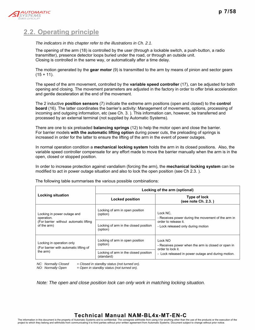
The following table summarises the various possible combinations:
Locking situation Locking of the arm (optional)
Locked position Type of lock (see note Ch. 2.3. )
Locking in power outage and operation. (For barrier without automatic lifting of the arm)
Locking of arm in open position (option) Lock NC,
- Receives power during the movement of the arm in order to release it.
- Lock released only during motion Locking of arm in the closed position (option)
Locking in operation only
(For barrier with automatic lifting of the arm)
Locking of arm in open position (option)
Lock NO
- Receives power when the arm is closed or open in order to lock it.
- Lock released in power outage and during motion. Locking of arm in the closed position (standard)
NC: Normally Closed = Closed in standby status (not turned on). NO: Normally Open = Open in standby status (not turned on).
Note: The open and close position lock can only work in matching locking situation.

p 8/58
Technical Manual NAM-BL4x-MT-EN-C The information in this document is the property of Automatic Systems and is confidential. The consignee withholds from using it for anything other than the use of the products or the execution of the project to which they belong and withholds from communicating it to third parties without prior written agreement from Automatic Systems. Document subject to change without prior notice.
2.3. Mechanical locking of the arm
The lock type NO in closed position is standard on the equipment. However locks are available as an option for the open position or in the NC type (locking in power outage).
These locks are placed on the reinforcing V-blocks (19), under the cover. Note: Depending on the desired operating mode (specified when the order is placed), the installed locks will be of NO (standard) or NC (option) type (see table in Ch. 2.2). However, for locking in both positions, the 2 locks will be systematically of the same type (NO or NC), as they are controlled by the same electromagnet.
The above illustration represents the locking of the arm in the open position by means of an NC lock. The operation described below corresponds to this configuration, but can be applied in principle to other configurations.
The lock is of the Normally Closed type: In standby mode (turned off), the spring (81) pushes the shank (82) out of the electromagnet (80), which closes the clips (83) around the locking pin (84). The locking pin being fastened to the hub (13), which in turn is attached to the arm’s driving shaft, which is therefore locked.
When a close command is sent to the barrier, the electromagnet is turned on. The shank (82) is pulled towards the electromagnet, which results in the clips (83) opening.
At the same time, a pulse is given to the arm in the other direction (opening), to unlock the mechanism (the clips could be stuck by the locking pin if the arm has been subjected to major stress in a locked position).
The closing of the arm is only started when the inductive sensor (86) detects the shank’s end washer, which corresponds to the opening of the clips and the unlocking of the arm.
If the arm is not unlocked within 3 seconds, the barrier is put out of service. Once the arm is closed (detection by the limit switch sensor (7, Ch. 2.1. ), the electromagnet is switched off.
LOCK NC DURING STANDBY (POWER OFF)
80
LOCK NC WHEN POWERED (POWER ON)
OPTION LOCKING OF THE ARM IN
OPEN POSITION
81 82
83
84
84
21
86
19. Reinforcing V-block (see Ch. 2.1. )
80. Electromagnet
81. Call back spring
82. Clip driving rod
83. Locking clips
84. Locking pin
86. Inductive sensor
19

p 9/58
Technical Manual NAM-BL4x-MT-EN-C The information in this document is the property of Automatic Systems and is confidential. The consignee withholds from using it for anything other than the use of the products or the execution of the project to which they belong and withholds from communicating it to third parties without prior written agreement from Automatic Systems. Document subject to change without prior notice.

p 10/58
Technical Manual NAM-BL4x-MT-EN-C The information in this document is the property of Automatic Systems and is confidential. The consignee withholds from using it for anything other than the use of the products or the execution of the project to which they belong and withholds from communicating it to third parties without prior written agreement from Automatic Systems. Document subject to change without prior notice.
3. AS1320 CONTROL BOARD
(Excract from AS1320 techniciean manual)
Legend
6:1. Fuses 6:2. Light indicating that the stabilised power supply is switched on 6:3. Menu display screen 6:4. Keys for navigating through the menu 6:5. Connector for the RJ45 communication cable 6:6. Terminal blocks for external communication (Input/Output connections) 6:7. Green LEDs (lights indicating that the control board has been turned on) 6:8. Connectors for presence detectors (for inductive loops)
6:1
6:2
6:3
6:7
6:4 6:5 6:8
6:6

p 11/58
Technical Manual NAM-BL4x-MT-EN-C The information in this document is the property of Automatic Systems and is confidential. The consignee withholds from using it for anything other than the use of the products or the execution of the project to which they belong and withholds from communicating it to third parties without prior written agreement from Automatic Systems. Document subject to change without prior notice.
The control board is the interface between the user and the barrier. It manages all of the latter’s actions, including any potential options. The navigation of the display menus is based on an architecture using drop-down menus with three levels: MENUS PARAMETERS VALUES. Use the ◄►keys to move from one level to another (hold down for a few seconds to move from the standby screen to another menu). Use the ▲▼ keys to navigate within the levels themselves. Press the OK key to validate a value modification.
Note: The second column in the tables below provides the factory settings of the parameter values as they are entered during manufacturing of the control board. Nevertheless, as each piece of equipment has been specifically adjusted in our workshops, the values actually present on the board may differ slightly.
Note: Below only the simplified menus are presented, which are sufficient for everyday use of the barrier. Please refer to the control board manual (available upon request) for a detailed description of all of the functions, adjusting their parameters, etc.
The menus are displayed on the first line, in capital letters and from the first character of the LCD.
Press ▲ or ▼ for a few seconds to leave the PRDSTD screen and access other menus.
Only the first letter of each word in the parameters is a capital. Parameters are displayed on the top line starting with the second character of the LCD (i.e., there is a space in front). At the end of the first line the parameter unit appears, if there is one.
The question mark (?) preceding the parameter indicates that the latter is ready to be modified. The current value of the parameter appears on the second line. The asterisk (*) under a parameter indicates that it is the factory setting.
The modification is validated by pressing the OK key.
Save the modifications in order to avoid losing them
during power outages (QUICK START ► Memory ► Save.
Menus Parameters
Arm Length
Barrier Type
Arm Type
? Arm Length * 3m00
? Arm Length 2m50
? Arm Length 2m00
? Arm Length 6m00
? Arm Length 3m50
? Arm Length 4m00
? Arm Length 4m50
? Arm Length 5m50
? Arm Length 5m00
CANCEL
VALIDATE OK
or
Values
QUICK START
PRDSTD - BL_xxx
DATE & TIME
CL REGULATION
TIMING
OUTPUT FUNCTION
SENSOR FUNCTION

p 12/58
Technical Manual NAM-BL4x-MT-EN-C The information in this document is the property of Automatic Systems and is confidential. The consignee withholds from using it for anything other than the use of the products or the execution of the project to which they belong and withholds from communicating it to third parties without prior written agreement from Automatic Systems. Document subject to change without prior notice.
3.1. PRDSTD – BL_xxx menu: Troubleshooting and monitoring
This screen appears when the unit is turned on and after there has not been any navigation through the menus in simplified mode for 100 seconds.
Parameter Values Description
OK key: (only within this menu (*) and when no other parameter is selected): command for opening and closing the obstacle. OK during opening: without effect. OK during closing: inversion (= opening). OK maintained: oscillating movement around the opening limit switch: the obstacle opens, starts closing, opens again, etc.
(*) Warning: in QUICKSTART menu, validating passage from Extended to Simplified menus through the OK key causes also an opening or closing movement of the arm, even if a presence is detected by the Presence sensors. Note: When the operating mode is configured as 1 contact (see the Exploitation parameter in the QUICK START menu), the obstacle closes automatically when the opening limit switch is detected.
Left key (◄): Change the menu display language with each touch. EN = English FR = Français NL = Nederlands DE = Deutsch ES = Español IT = Italiano SV = Svenska Select the language using the OK key or allow it to change automatically after a few seconds, following which all of the preceding parameter modifications (including the language) will be saved in MEM1.
Name of the program
Date (DD/MM) Time (hh:mm)
Choice of languageby means of the ◄
button

p 13/58
Technical Manual NAM-BL4x-MT-EN-C The information in this document is the property of Automatic Systems and is confidential. The consignee withholds from using it for anything other than the use of the products or the execution of the project to which they belong and withholds from communicating it to third parties without prior written agreement from Automatic Systems. Document subject to change without prior notice.
Soft. Version Display the software version used by the control unit, following format type – evolution – version – revision – minor index of the application.
The descriptions included in this chapter correspond to versions 00-00-06-rr-00.
Log Display of the last 100 events (use ► the ▲ and keys to view preceding events). For the first two seconds, the event number (00 for the last event recorded (= most recent), 01 for the preceding event, and so on), as well as the date (year-month-day) and time (hours-minutes-seconds) of creation are displayed. In the next two seconds, the event description is displayed. For example:
2 s Log 00 060324 235034
On 24 March 2006 at 23 hours (11 p.m.) 50 minutes and 34 seconds…
2 s Log Out Of Service
…the apparatus was put out of service.
2 s Log 01 060324 235034
View the preceding message (01) using the ►▲ keys…
2 s Log Open Time Out
…we observe that it was put out of service due to a time out while opening.
Note: If no error message is displayed when the machine fails, refer to the Troubleshooting chapter.
Power Up Power was turned on.
Power Down Power was turned off.
Short Circuit Short circuit of the control board outputs (connector blocks). The short circuit is declared and the equipment put Out of Service only after 3 unsuccessful reactivation tries within the 2.5 seconds following a voltage drop in the 24V power supply (this is to avoid putting it out of service at inopportune moments, as for example during a network changeover to an emergency generator).
If one of the outputs short circuits, all of them become inactive and the control board must be powered up again for the outputs to be reactivated.
Open Time Out Time out during opening: the time allocated for opening was exceeded (TIMING menu, OpenTimeOut parameter).
Close Time Out Time out during closing: the time allocated for closing was exceeded (TIMING menu, CloseTimeOut parameter).
Close Retries Allotted number of trials to close have been executed (as defined in the TIMING menu).

p 14/58
Technical Manual NAM-BL4x-MT-EN-C The information in this document is the property of Automatic Systems and is confidential. The consignee withholds from using it for anything other than the use of the products or the execution of the project to which they belong and withholds from communicating it to third parties without prior written agreement from Automatic Systems. Document subject to change without prior notice.
Arm Swing Off Arm detected out of its support jaw (see the Arm Swing Off parameter in the OPTIONS menu).
If the message continues to be displayed after the arm is rehinged, check the status of the SW arm presence sensor and its fastening
Out Of Service Apparatus out of service. This may be caused by the following events:
1) Time out during opening (see Open Time Out message).
2) Time out during closing (see Close Time Out error) + allotted number of tries to close have been executed (see Close Retries message).
3) Arm is unhinged (see Arm Swing Off message).
4) Locking or unlocking failure of the BL4x (see Unlock BL4x Er message).
5) Defect of the frequency inverter.
Time Adjust Modification of the date and time.
Access Level Chg Change to the access level.
OOS Restore Apparatus put back in service (after it has been out of service) => see the RestartMode parameter under the OPTIONS menu.
Test Intensive Activation of the intensive test.
Lock Open The Lock Open command of the test mode has been activated.
Lock Close The Lock Close command of the test mode has been activated.
Safety Arm Safety arm (only with the rubber protection profile option: Rubber strip that detects when the arm makes contact with a vehicle).
Sw Manual Frequency converter power cut-off in order to prevent any movement of the obstacle in case of:
Crank presence sensor activation (available on some equipment for manual handling of the obstacle),
Door/hood opening sensors activation (option on some equipment).
Reset Sensor Init Change of the positioning sensor type (cf. Positioning parameter of QUICKSTART menu).
LS Fault Both opening and closing limit switches are activated simultaneously or badly connected during 100 ms, while Positioning parameter of the QUICKSTART menu is set to Limit Switches.
Reset LS Fault Limit switch problem resolved (see LS Fault error).

p 15/58
Technical Manual NAM-BL4x-MT-EN-C The information in this document is the property of Automatic Systems and is confidential. The consignee withholds from using it for anything other than the use of the products or the execution of the project to which they belong and withholds from communicating it to third parties without prior written agreement from Automatic Systems. Document subject to change without prior notice.
Analog. Fault The analogue sensor gives 0 or 1023 during minimum 100 ms. This may result from a defective wiring, a wrong positioning of the sensor in front of its cam, a defective sensor, etc.
OP Power Cut Unlocking of the obstacle following an outage of the supply voltage (if QUICK START ► Power Fail OP ► ON).
OP Power Blip Unlocking of the obstacle following a micro-outage of the supply voltage (the voltage drops to 0 V during a few milliseconds) (if QUICK START ► Power Fail OP ► ON). In this state, the obstacle is STOPPED but still operational, because the supply voltage has returned. The apparatus waits for the next command to execute a movement.
CoolingMotor ON Start-up of the motor cooling fan.
Note: This message is only displayed if the Cooling – Log (below) is ON.
CoolingMotor OFF Stopping of the fan that cools the motor.
Note: This message is only displayed if the Cooling – Log (below) is ON.
Stop Time Out Elapse of the delay defined under the Max Stop parameter of the TIMING menu for the regulation of the obstacle position with regard to the Stop.
Download Chg Lv1 Downloading a version of the control board program that differs from the one previously installed. As the difference is of level 1 (minor index modification or revision), the parameters continue operate with their value saved in MEM1.
Download Chg Lv2 Downloading a version of the control board program that differs from the one previously installed. As the difference is of level 2 (modification of the version or the evolution), all of the parameters are returned to their default values.
WARNING: it is then necessary to set the parameters to the actual configuration of the equipment and to save them in MEM1.
Note: it would be wise to keep the parameters values before changing the program version: Communication parameter Extract Param (Technician level access).
Download Chg Lv3 Downloading a version of the control board program that differs from the one previously installed. As the difference is of level 3 (modification of the type), all of the parameters are returned to their default values and the counters are reset to 0.
WARNING: it is then necessary to set the parameters to the actual configuration of the equipment and to save them in MEM1.
Note: it would be wise to keep the parameters values before changing the program version: Communication parameter Extract Param (Technician level access).

p 16/58
Technical Manual NAM-BL4x-MT-EN-C The information in this document is the property of Automatic Systems and is confidential. The consignee withholds from using it for anything other than the use of the products or the execution of the project to which they belong and withholds from communicating it to third parties without prior written agreement from Automatic Systems. Document subject to change without prior notice.
Reset Counters Counters reset to zero following the download of a different program version of level 3 (see Download Chg Lv3).
Curve 229Std Change in the type of barrier: selection of curve 229 standard (Barrier Type parameter under the QUICK START menu).
Curve 229Highway Change in the type of barrier: selection of curve 229 highway (Barrier Type parameter under the QUICK START menu).
Curve 1x-2x-3x-5x Change in the type of barrier: selection of curve for BL16, BL32, BL33, BL52, BL53 (Barrier Type parameter under the QUICK START menu).
Curve BLG77 Change in the type of barrier: Selection of curve BLG77 (Barrier Type parameter under the QUICK START menu).
Curve Special Change in the type of barrier: selection of the Special curve (OPTIONS menu) for operation according to the OP REGULATION and CL REGULATION menus.
Curve BL223 Change in the type of barrier: Selection of curve BL223 (Barrier Type parameter under the QUICK START menu).
Curve BL40 AVR Change in the type of barrier: Selection of curve BL40 AVR (Barrier Type parameter under the QUICK START menu).
Curve BL40 SR Change in the type of barrier: Selection of curve BL40SR (Barrier Type parameter under the QUICK START menu).
Curve BL41 AVR Change in the type of barrier: Selection of curve BL41AVR (Barrier Type parameter under the QUICK START menu).
Curve BL41 SR Change in the type of barrier: Selection of curve BL41SR (Barrier Type parameter under the QUICK START menu).
Curve BL43 AVR Change in the type of barrier: Selection of curve BL43AVR (Barrier Type parameter under the QUICK START menu).
Curve BL43 SR Change in the type of barrier: Selection of curve BL43SR (Barrier Type parameter under the QUICK START menu).
Curve BL44 AVR Change in the type of barrier: Selection of curve BL44AVR (Barrier Type parameter under the QUICK START menu).
Curve BL44 SR Change in the type of barrier: Selection of curve BL44SR (Barrier Type parameter under the QUICK START menu).
Curve BL46 AVR Change in the type of barrier: Selection of curve BL46AVR (Barrier Type parameter under the QUICK START menu).
Curve BL46 SR Change in the type of barrier: Selection of curve BL46SR (Barrier Type parameter under the QUICK START menu).
Curve RSB 70&71 Change in the type of equipment: Selection of curve RSB 70&71 (Barrier Type parameter under the QUICK START menu).

p 17/58
Technical Manual NAM-BL4x-MT-EN-C The information in this document is the property of Automatic Systems and is confidential. The consignee withholds from using it for anything other than the use of the products or the execution of the project to which they belong and withholds from communicating it to third parties without prior written agreement from Automatic Systems. Document subject to change without prior notice.
Unlock BL4x Er Only with locking of the arm option for BL4x. The inductive sensor has not detected the release of the lock within the 3 seconds following the open or close request: check whether the locking pin is pressing on the locking clips, preventing them form opening, or whether the sensor is defective.
Close Status Cases when the obstacle is prevented from closing during a close request:
OK Normal closure.
PS1 Activated A sensor (loop/cell) detects a presence or a fault in the
circuit. In the latter case:
Check whether the sensor is plugged into the corresponding connector and whether it is functioning properly.
Check whether the sensor is properly connected.
Check whether the sensors are programmed correctly (SENSOR FUNCTION menu).
PS2 Activated
PS3 Activated
PS4 Activated
Lock OP Hold Check why the Lock Open command is being maintained on the control board connector block.
Safe Arm Activ Activation of the Safety Arm sensor (only with the rubber protection profile option: rubber strip that detects when the arm makes contact with a vehicle):
Check whether the arm safety sensor is functioning properly.
Check whether the Safety Arm parameter is programmed correctly (Options menu).
PWF Open Activ Setting of the PWF Open Activ parameter of the OPTIONS menu to ON, that is to say that during activation the obstacle opens and waits for the activation of a close or lock-close command.
Note: the closure loops are not taken into account for closing in this case.
Lock Open LCD The Test Mode parameter of the TEST menu is not set to Deactivated.
Delay Befor CL Wait for the delay programmed under the Delay Befor. CL parameter under the TIMING menu to elapse.
Open Cmd Hold Check why the open command is being maintained on the control board connector block.
Stop Cmd Hold Check why the stop command is being maintained on the control board connector block.
Check whether the Stop Cmd parameter is programmed correctly (Options menu).
Reader A Hold Check why the Reader A command is being maintained on the control board connector block.
Reader B Hold Check why the Reader B command is being maintained on the control board connector block
p 18/58
Technical Manual NAM-BL4x-MT-EN-C The information in this document is the property of Automatic Systems and is confidential. The consignee withholds from using it for anything other than the use of the products or the execution of the project to which they belong and withholds from communicating it to third parties without prior written agreement from Automatic Systems. Document subject to change without prior notice.
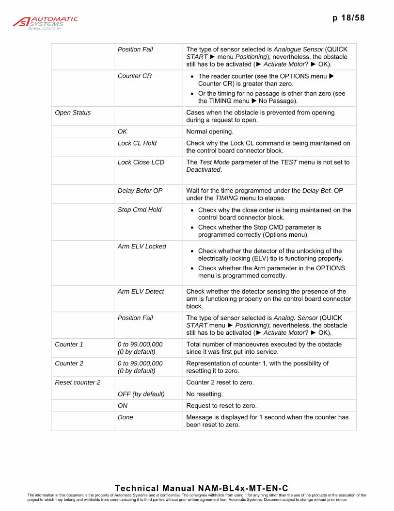
Position Fail The type of sensor selected is Analogue Sensor (QUICK START ► menu Positioning); nevertheless, the obstacle still has to be activated (► Activate Motor? ► OK).
Counter CR The reader counter (see the OPTIONS menu Counter CR) is greater than zero.
Or the timing for no passage is other than zero (see the TIMING menu No Passage).
Open Status Cases when the obstacle is prevented from opening during a request to open.
OK Normal opening.
Lock CL Hold Check why the Lock CL command is being maintained on the control board connector block.
Lock Close LCD The Test Mode parameter of the TEST menu is not set to Deactivated.
Delay Befor OP Wait for the time programmed under the Delay Bef. OP under the TIMING menu to elapse.
Stop Cmd Hold Check why the close order is being maintained on the control board connector block.
Check whether the Stop CMD parameter is programmed correctly (Options menu).
Arm ELV Locked Check whether the detector of the unlocking of the
electrically locking (ELV) tip is functioning properly.
Check whether the Arm parameter in the OPTIONS menu is programmed correctly.
Arm ELV Detect Check whether the detector sensing the presence of the arm is functioning properly on the control board connector block.
Position Fail The type of sensor selected is Analog. Sensor (QUICK START menu ► Positioning); nevertheless, the obstacle still has to be activated (► Activate Motor? ► OK).
Counter 1 0 to 99,000,000 (0 by default)
Total number of manoeuvres executed by the obstacle since it was first put into service.
Counter 2 0 to 99,000,000 (0 by default)
Representation of counter 1, with the possibility of resetting it to zero.
Reset counter 2 Counter 2 reset to zero.
OFF (by default) No resetting.
ON Request to reset to zero.
Done Message is displayed for 1 second when the counter has been reset to zero.
p 19/58
Technical Manual NAM-BL4x-MT-EN-C The information in this document is the property of Automatic Systems and is confidential. The consignee withholds from using it for anything other than the use of the products or the execution of the project to which they belong and withholds from communicating it to third parties without prior written agreement from Automatic Systems. Document subject to change without prior notice.
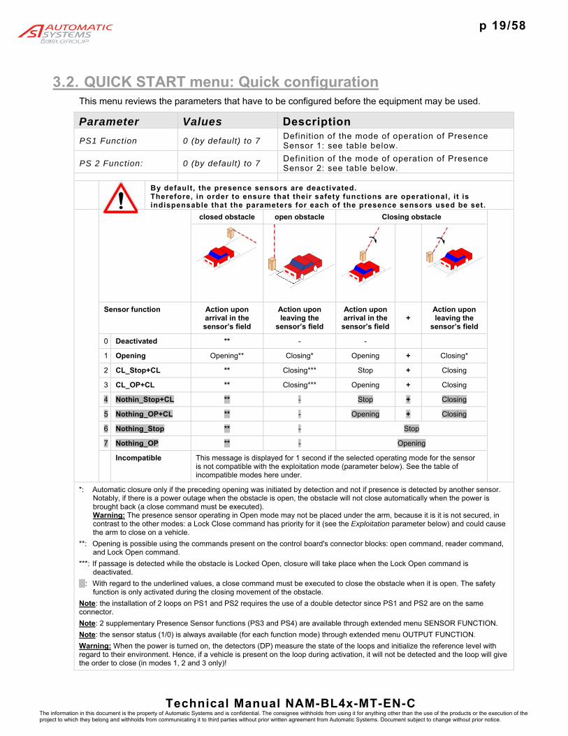
3.2. QUICK START menu: Quick configuration This menu reviews the parameters that have to be configured before the equipment may be used.
Parameter Values Description
PS1 Function 0 (by default) to 7 Definition of the mode of operation of Presence Sensor 1: see table below.
PS 2 Function: 0 (by default) to 7 Definition of the mode of operation of Presence Sensor 2: see table below.
By default, the presence sensors are deactivated.
Therefore, in order to ensure that their safety functions are operational, it is indispensable that the parameters for each of the presence sensors used be set.
closed obstacle open obstacle Closing obstacle
Sensor function Action upon arrival in the sensor’s field
Action upon leaving the
sensor’s field
Action upon arrival in the sensor’s field
+ Action upon leaving the
sensor’s field
0 Deactivated ** - -
1 Opening Opening** Closing* Opening + Closing*
2 CL_Stop+CL ** Closing*** Stop + Closing
3 CL_OP+CL ** Closing*** Opening + Closing
4 Nothin_Stop+CL ** - Stop + Closing
5 Nothing_OP+CL ** - Opening + Closing
6 Nothing_Stop ** - Stop
7 Nothing_OP ** - Opening
Incompatible This message is displayed for 1 second if the selected operating mode for the sensor is not compatible with the exploitation mode (parameter below). See the table of incompatible modes here under.
*: Automatic closure only if the preceding opening was initiated by detection and not if presence is detected by another sensor. Notably, if there is a power outage when the obstacle is open, the obstacle will not close automatically when the power is brought back (a close command must be executed). Warning: The presence sensor operating in Open mode may not be placed under the arm, because it is it is not secured, in contrast to the other modes: a Lock Close command has priority for it (see the Exploitation parameter below) and could cause the arm to close on a vehicle.
**: Opening is possible using the commands present on the control board's connector blocks: open command, reader command, and Lock Open command.
***: If passage is detected while the obstacle is Locked Open, closure will take place when the Lock Open command is deactivated.
: With regard to the underlined values, a close command must be executed to close the obstacle when it is open. The safety function is only activated during the closing movement of the obstacle.
Note: the installation of 2 loops on PS1 and PS2 requires the use of a double detector since PS1 and PS2 are on the same connector.
Note: 2 supplementary Presence Sensor functions (PS3 and PS4) are available through extended menu SENSOR FUNCTION.
Note: the sensor status (1/0) is always available (for each function mode) through extended menu OUTPUT FUNCTION.
Warning: When the power is turned on, the detectors (DP) measure the state of the loops and initialize the reference level with regard to their environment. Hence, if a vehicle is present on the loop during activation, it will not be detected and the loop will give the order to close (in modes 1, 2 and 3 only)!

p 20/58
Technical Manual NAM-BL4x-MT-EN-C The information in this document is the property of Automatic Systems and is confidential. The consignee withholds from using it for anything other than the use of the products or the execution of the project to which they belong and withholds from communicating it to third parties without prior written agreement from Automatic Systems. Document subject to change without prior notice.
Positioning Definition of the type of sensor used to position the obstacle.
Limit Switches (by default)
To be selected if the open/close position is determined by limit switches (standard for BL4x).
Analog. Sensor To be selected if the position of the obstacle is determined by an analogue sensor.
The analogue position sensor measures the distance separating it from a spiral cam located on the shaft that transmits the movement of the obstacle’s motor, which means that the angular position of the obstacle is known at all times. Also, see the Min Sensor Max parameter below.
Manual Switch This message is displayed if it is not possible to activate the analogue sensor, as per one of these cases:
The crank presence detector (only present on some equipments) is engaged. => Remove the crank so that the motor may be engaged.
If the equipment does not have a crank presence detector, the circuit may have been cut. => link the corresponding connections.
Activate Motor? Pushing the OK key within 5 seconds launches the analogue sensor activation procedure (see below) and the movement of the obstacle!
The Barrier Type and Arm characteristics must be selected BEFORE initializing the analogue sensor. Otherwise, rough movements of
the arm can occur with risk of injury for the personnel and the equipment.
=> Navigate through the menus by means of the upper key ().
Search LSO… The obstacle opens to look for its open limit position.
The obstacle is moving during this phase!
Search LSC… The obstacle closes to look for its closed limit position.
Init. Passed This is displayed if the open and closed limit values have been recorded. The analogue sensor is then operational.
The message disappears after 5 seconds or if the OK key is pushed.
IMPORTANT: Save the values in MEM1 or MEM2 (MEMORY menu).

p 21/58
Technical Manual NAM-BL4x-MT-EN-C The information in this document is the property of Automatic Systems and is confidential. The consignee withholds from using it for anything other than the use of the products or the execution of the project to which they belong and withholds from communicating it to third parties without prior written agreement from Automatic Systems. Document subject to change without prior notice.
Adjust Sensor Activation failed because the analogue sensor was not properly positioned => adjust it (closer or further away from the cam) so the measurement is included in the working range (= between the min. and the max. set in the Min Sensor Max parameter below).
Value 0 Detect Activation failed because the analogue sensor returned a measurement of zero. As this value is invalid, check:
the sensor’s wiring (in the sensor as well as on the control board's connector blocks);
whether is sensor is too close to the cam;
whether the sensor is functioning: LED on the sensor is illuminated and the value measured is displayed in the Min Sensor Max parameter below.
Barrier Type Definition of the equipment type; this allows the program to automatically modify the opening and closing motor power curves.
Note 1: The equipment type is stated on the reference plate, inside the housing.
Note 2: to change from barrier solution 1 or 2 to solution 3 or 4 (illustration below), 2 phases of the motor have to be inverted.
229 Standard (by default)
Parameter to select for a BL229 Standard.
229 Highway Parameter to select for a BL229 Highway.
1x – 2x – 3x – 5x Parameter to select for a BL16, BL32, BL33, BL52, BL53, BP56, RSB70, or RSB71.
BLG77 Parameter to select for a BLG77.
BL 223 Parameter to select for a BL223.
RSB 70 & 71 Parameter to select for a RSB 70 or RSB 71.
BL 40 SR Parameter to select for a BL40 without automatic opening of the arm in case of power cut.
BL40 AVR Parameter to select for a BL40 with automatic opening of the arm in case of power cut.
BL 41 SR Parameter to select for a BL41 without automatic opening of the arm in case of power cut.
BL 41 AVR Parameter to select for a BL41 with automatic opening of the arm in case of power cut.
BL 43 SR Parameter to select for a BL43 without automatic opening of the arm in case of power cut.
door door
door door
door
door
door
door
road
Solution 1 Solution 2 Solution 3 (standard)
Solution 4

p 22/58
Technical Manual NAM-BL4x-MT-EN-C The information in this document is the property of Automatic Systems and is confidential. The consignee withholds from using it for anything other than the use of the products or the execution of the project to which they belong and withholds from communicating it to third parties without prior written agreement from Automatic Systems. Document subject to change without prior notice.
BL 43 AVR Parameter to select for a BL43 with automatic opening of the arm in case of power cut.
BL 44 SR Parameter to select for a BL44 without automatic opening of the arm in case of power cut.
BL44 AVR Parameter to select for a BL44 with automatic opening of the arm in case of power cut.
BL 46 SR Parameter to select for a BL46 without automatic opening of the arm in case of power cut.
BL 46 AVR Parameter to select for a BL46 with automatic opening of the arm in case of power cut.
Arm Length Specification of the arm mounted on the barrier; this allows the program to automatically modify the opening and closing curves.
If the selected length does not correspond to a standard for the barrier selected in the Barrier Type parameter, the message “Doesn't Exist” appears briefly.
Note: arm length = free passage = distance between the arm tip and the barrier housing.
2m00 Select this for a BL4x or BL229 with an arm of 2 m.
2m50 Select this for a BL4x or BL229 with an arm of 2.5 m.
3m00 Select this for a BL4x or BL229 with an arm of 3 m.
3m50 Select this for a BL4x or BL229 with an arm of 3.5 m.
4m00 Select this for a BL4x or BL229 with an arm of 4 m.
4m50 Select this for a BL4x or BL229 with an arm of 4.5 m.
5m00 (by default) Select this for a BL4x or BL229 with an arm of 5 m.
5m50 Select this for a BL4x or BL229 with an arm of 5.5 m.
6m00 Select this for a BL4x or BL229 with an arm of 6 m.
7m00 Select this for a BL4x with an arm of 6,5 or 7 m.
8m00 Select this for a BL4x with an arm of 7,5 or 8 m.
9m00 Select this for a BL4x with an arm of 8,5 or 9 m.
10m00 Select this for a BL4x with an arm of 9,5 or 10 m.
11m00 Select this for a BL4x with an arm of 10,5 or 11 m.
12m00 Select this for a BL4x with an arm of 11,5 or 12 m.
Arm length

p 23/58
Technical Manual NAM-BL4x-MT-EN-C The information in this document is the property of Automatic Systems and is confidential. The consignee withholds from using it for anything other than the use of the products or the execution of the project to which they belong and withholds from communicating it to third parties without prior written agreement from Automatic Systems. Document subject to change without prior notice.
Non-modifiable This message is displayed when the Barrier Type parameter does not allow any modification of the arm length.
Incompatible Message displayed when the selected Arm Length is not compatible with the selected Barrier Type.
Arm Type Specification of the type of arm assembled on the barrier. This parameter only applies to the BL Highway and is not taken into account for other types of equipment.
Aluminium (default) Aluminium arm.
Carbon Carbon arm.
Non-modifiable Message displayed for the equipments different than BL229 Highway.
Power Fail OP Choice(*) of mode for unlocking the obstacle during a loss of supply voltage.
(*) Except for BL4x, where this parameter is automatically set to ON and not adjustable.
OFF (by default, except for BL4x)
The obstacle remains mechanically locked, thanks to the position of the transmission elements between them. Nevertheless, it is possible to unlock it manually using a lever or a crank.
ON (by default for BL4x only, not adjustable)
The obstacle is unlocked: a pulse is given to take the transmission elements out of alignment; opening may have to be effected by hand.
This electrical opening is only available for equipment that has a reversible motor reduction drive and a frequency inverter (thanks to the capacitors integrated into the control board and the frequency inverter).
Note: for BL4x AVR (with automatic opening of the arm in case of power failure) subjected to great forces (strong winds or fraud attempts to manually open the arm), the locking pin might press against the locking clips and prevent the automatic opening of the lock in case of power failure. This parameter gives the necessary reversed impulse to release the lock. For the BL4x SR (without automatic opening), this parameter has no effect because the electromagnetic brake will lock the arm in position in any case.
Warning: this adjustment is incompatible with the Lock Closed command which has priority and will maintain the obstacle closed.

p 24/58
Technical Manual NAM-BL4x-MT-EN-C The information in this document is the property of Automatic Systems and is confidential. The consignee withholds from using it for anything other than the use of the products or the execution of the project to which they belong and withholds from communicating it to third parties without prior written agreement from Automatic Systems. Document subject to change without prior notice.
Exploitation Operating modes for the opening, closing and STOP commands.
The commands follow this decreasing order of priority:
STOP (stop) Lock OP (lock open) Lock CL (lock close) OP (open) CL (close)
The presence sensors and reader inputs are at the same hierarchical level as OP/STOP/CL => Lock Close has priority in an opening loop and will work even if something is detected.
Warning: The OP command is never interrupted (the arm always goes to the LSO before accepting the next command) => Lock Close will take affect after the obstacle has reached its LSO.
Note: Some use modes are incompatible with the operating mode of the presence sensors (see the table of incompatible modes, here after).
2 Contacts (by default)
2 contacts used for opening and closing, on the control board's connector block. Open Cmd: open the obstacle Close Cmd: close the obstacle on the rising edge of the command. STOP Cmd: stop.
Note: A Lock Open command is given if the No Passage timing has been activated, it will close when the following two conditions have been met:
the Lock Open command is off,
the set time has elapsed (or, immediately if there is a detection on a closing sensor).
1 Contact Open Cmd: if active, the obstacle opens. Open Cmd: if inactive, the obstacle closes. STOP Cmd: stop. When the stop is released, the obstacle will continue to open if an OP/Lock Open command is still present, if not the obstacle will close.
Note: there is no CL contact in this mode.
Note: if this mode is used for a reader, it must be ensured that the latter sends a continuous signal in order for the obstacle to be kept open for a given time.
Note: this mode is highly recommended for barriers which arm is Normally Open (tunnel entry, etc.). In this case effectively, it is mandatory to maintain a continuous opening command in order to prevent an untimely closing (by maintenance personnel for example).
Warning: if there is a voltage loss while the obstacle is open, the obstacle will close when the power comes back if the OP command is not activated, because – in this mode – an inactive open command equals a close command.

p 25/58
Technical Manual NAM-BL4x-MT-EN-C The information in this document is the property of Automatic Systems and is confidential. The consignee withholds from using it for anything other than the use of the products or the execution of the project to which they belong and withholds from communicating it to third parties without prior written agreement from Automatic Systems. Document subject to change without prior notice.
Step by Step Open Cmd: inversion at each rising edge (i.e., at each pulse). STOP Cmd: stop.
Note: neither CL nor reader commands are available in this mode.
Dead Man Open Cmd: if active, the obstacle opens. Open Cmd: if inactive (i.e., when the command is released), stop. Close Cmd: If active, the obstacle closes. Close Cmd: if inactive, stop. STOP Cmd: stop.
Note: the reader commands do not work in this mode.
Note: this mode is only compatible with presence sensors operating under the Nothing_Stop or Deactivated modes (otherwise the Incompatible message appears briefly).
2 Contacts CFE Same as 2 Contacts operation, except: Close Cmd: Closure of the obstacle on the Falling Edge of the command (i.e., when the button is released).
Incompatible This message is displayed for one second if the operating mode selected is not compatible with the parameters set for the presence sensors.
Memory Save the parameter values (see MEMORY menu).
Ignored (by default) No action.
Save Save the modified parameters in MEM1.
Note: this saving action is necessary so that the modifications made are not lost during a power cut!
Load Default Recall the default values (factory settings) of the parameters accessible in the level from which this command is executed. E.g.: If you are in the Simplified menus, this function will only load the default values of the parameters accessible in Simplified menu, and will not modify the values of the parameters accessible in Extended or Manufacturer menus.
Warning: the loading of the default parameters entails the loss of the parameters specific to the installation’s real situation and may put the equipment out of service.
Done This message is displayed when the save or the load is finished and disappears automatically after 1 second.
Min Sensor Max 0 to 1024 This parameter applies to the analogue sensor (see the Positioning parameter above) and allows viewing the current value of the sensor (Sensor) (reflection of the angular position of the obstacle) in its measurement range (Min and Max being the sensor values at the extreme positions of the obstacle: completely open and closed).

p 26/58
Technical Manual NAM-BL4x-MT-EN-C The information in this document is the property of Automatic Systems and is confidential. The consignee withholds from using it for anything other than the use of the products or the execution of the project to which they belong and withholds from communicating it to third parties without prior written agreement from Automatic Systems. Document subject to change without prior notice.
Menu Access Choice of the display mode for the menus.
Simplified (default) Access to the menus included in the Simplified mode.
Warning: pressing the OK key to validate the passage from the Extended to the Simplified mode causes a movement of the arm (opening or closing), even if a presence is detected by the Presence sensors.
Extended Access to supplementary parameters.
Incompatibility table of presence sensor (PS) use and operating modes: compatible incompatible
Use mode
2 Contacts 1 Contact
Step by Step
Dead Man 2 Contacts CFE
Sen
sor
func
tion
Desactivated
Opening
CL_Stop+CL
CL_OP+CL
Nothing_Stop+CL
Nothing_OP+CL
Nothing_Stop
Nothing_OP

p 27/58
Technical Manual NAM-BL4x-MT-EN-C The information in this document is the property of Automatic Systems and is confidential. The consignee withholds from using it for anything other than the use of the products or the execution of the project to which they belong and withholds from communicating it to third parties without prior written agreement from Automatic Systems. Document subject to change without prior notice.
4. INSTALLATION Installation must be undertaken in compliance with the safety warnings (Ch. 1. ).
4.1. Storing the equipment before installation
Before installation, ensure that the equipment does not get damaged, leave it in its original packaging, and place it in a dry area protected from dust, heat and weather. Store between -30 and +80°C [-22°F and 176°F].
4.2. Positioning the equipment
Since the barrier cannot be laid flush with the road surface, a perfectly horizontal raised concrete base must be prepared, according to the installation drawing provided with the equipment.
1. Assemble the fixing frame: Pass the four anchoring bolts (2) into the holes of the fixing frame (1) using a nut (7a) and a flat washer (6a) each time. The threaded must be installed as illustrated in Fig. a. Secure the anchoring bolts on the fixing frame by putting a flat washer (6b) and a nut (7b) on each threaded rod with a 40 mm [1,57 in] tail. Tighten the nuts. It is advisable to protect the threads sticking out of the fixing frame from concrete projections by means of adhesive tape.
2. Provide 2 PVC tube (3 & 4) of minimum diameter 25.4mm [1 in]. One conduit for the power supply and one for the remote control wires (Fig. b). When appropriate, pass a PVC tube (5) of diameter 25 mm [1 in] to pass the optional detection loops wires. Ensure that the cables have a minimum of 1 metre [3.3 ft] out of the concrete base.
3. Construct a concrete base (8) in which the fixing frame is to be buried. The fixing frame must be flush with the finished level of the concrete base and perfectly horizontal (Fig. b).
4. When the concrete is dry, remove the adhesive protection tape from the threads, remove the nuts (7b), the flat washers (6b), put the barrier housing onto the concrete base and maintain it by means of the washers (6b) and the nuts (7b) (Fig. c). The concrete base is designed smaller than the barrier housing in order to prevent water stagnating at the bottom of the housing.
Fig. c
Fig. dFig. b
40 mm
35
8
4

p 28/58
Technical Manual NAM-BL4x-MT-EN-C The information in this document is the property of Automatic Systems and is confidential. The consignee withholds from using it for anything other than the use of the products or the execution of the project to which they belong and withholds from communicating it to third parties without prior written agreement from Automatic Systems. Document subject to change without prior notice.
4.3. Assembly of the round arm for BL40
10 Upper bumper 13 Hub30 Balancing spring 54 Nut 57 Pin70 CBLH M8x25 stainless steel screw (tighten to 20
Nm)71 Round aluminium arm, Ø10072 Round aluminium arm, Ø89.5 or Ø83.573 Assembly fixing bracket for round arm74 H M C12x120 stainless steel screw (tighten to 80
Nm)75 M 12 stainless steel flat washer 76 Nylstop M12 stainless steel nut 77 Main shaft
77
10
54
19
57
13
30

p 29/58
Technical Manual NAM-BL4x-MT-EN-C The information in this document is the property of Automatic Systems and is confidential. The consignee withholds from using it for anything other than the use of the products or the execution of the project to which they belong and withholds from communicating it to third parties without prior written agreement from Automatic Systems. Document subject to change without prior notice.
Note: All screws must be lubricated before assembly.
Note: Minimum tightening torques are provided in the illustration’s legend.
Warning: In the event of removing the arm assembly, the spring assemblies’ lower fastening pin (57) must be removed beforehand, in order to release the tension in the springs.
1. Turn off the power to the barrier by turning off the circuit breaker (20, Ch. 2.1. ).
2. Unlock the nut (54) and screw the upper bumper (10) as far as possible into the hub (13), in order to remove the compression constraint on the springs (30), then lift the shaft (77).
3. Remove the spring assembly’s lower hinge pin (57).
4. Slowly lower the arm stirrup. If the barrier is equipped with the mechanical locking unlock the system first by pulling on the electromagnet shank.
5. Place the first arm coupler (71) on the arm rotating shaft (77). Tighten the screws (74), washers (75) and nuts (76). Place the second arm coupler (72), if any, in the first one and tighten the screws (70). Place the third arm coupler (72), if any, in the second one and tighten the screws (70).
6. Lift the arm, if needed, unlock the system.
7. Replace the spring assembly’s lower fastening axle and lock it using its pin (57).
8. Adjust the verticality of the arm by tightening or loosening the upper bumper (10), then tighten the lock nut (54).
9. Fasten and, where necessary, tighten the bracing wire (see illustration on the folding fence, below).

p 30/58
Technical Manual NAM-BL4x-MT-EN-C The information in this document is the property of Automatic Systems and is confidential. The consignee withholds from using it for anything other than the use of the products or the execution of the project to which they belong and withholds from communicating it to third parties without prior written agreement from Automatic Systems. Document subject to change without prior notice.
4.4. Assembly of the central round arm for BL41
10 Upper bumper13 Hub30 Balancing spring54 Nut 57 Pin70 Round aluminium arm, Ø100 71 Fixing bracket for central arm 72 Central stirrup for round arm (in 2 parts)73 M 12 stainless steel flat washer 74 H M12x40 stainless steel screw (tighten to
80 Nm)75 M 16 stainless steel flat washer 76 H M16x40 stainless steel screw (tighten to
190 Nm)77 H M16x40 stainless steel screw (standard);
H M16x50 screw if bracings (tighten to 190 Nm).
78 H M14x100 stainless steel screw (tighten to 130 Nm)
79 M 14 stainless steel flat washer 80 Fixing jaw81 Clavette82 Nylstop M14 stainless steel nut 83 Shaft for stirrup
72
10
54
19
57
13
30

p 31/58
Technical Manual NAM-BL4x-MT-EN-C The information in this document is the property of Automatic Systems and is confidential. The consignee withholds from using it for anything other than the use of the products or the execution of the project to which they belong and withholds from communicating it to third parties without prior written agreement from Automatic Systems. Document subject to change without prior notice.
Note: All screws must be lubricated before assembly.
Note: Minimum tightening torques are provided in the illustration’s legend.
Warning: In the event of removal of the arm assembly, the spring assemblies’ lower fastening axle must be removed beforehand by removing the pin (57), in order to release the tension in the springs.
1. Turn off the power to the barrier by turning off the circuit breaker (20, Ch. 2.1. ).
2. Unlock the nut (54) and screw the upper bumper (10) as far as possible into the hub (13), in order to remove the compression constraint on the springs (30), then lift the stirrup (72).
3. Remove the spring assembly’s lower hinge pin (57).
4. Slowly lower the arm stirrup. If the barrier is equipped with the mechanical locking unlock the system first by pulling on the electromagnet shank.
5. Place the first arm coupler (70) on the stirrup (72). Tighten the screws (74), washers (73) and fixing brackets (71). Place the second arm coupler, if any, into the first (see Arm assembly for BL40).
6. Lift the arm, if needed, unlock the system.
7. Replace the spring assembly’s lower fastening axle and lock it using its pin (57).
8. Adjust the verticality of the arm by tightening or loosening the upper bumper (10), then tighten the lock nut (54).
9. Fasten and, where necessary, tighten the bracing wire (see illustration on the folding fence, below).

p 32/58
Technical Manual NAM-BL4x-MT-EN-C The information in this document is the property of Automatic Systems and is confidential. The consignee withholds from using it for anything other than the use of the products or the execution of the project to which they belong and withholds from communicating it to third parties without prior written agreement from Automatic Systems. Document subject to change without prior notice.
4.5. Assembly of the oval arm for BL43 & BL44
10 Upper bumper 13 Hub30 Balancing spring 54 Nut 57 Pin70 Aluminium 175x100 arm 71 Fixing bracket for 175x100 arm 72 Central stirrup 73 M 16 stainless steel flat washer74 H M16x40 stainless steel screw (tighten to
190 Nm)75 H M14x100 stainless steel screw (tighten to
130 Nm)76 M 14 stainless steel flat washer77 Nylstop M14 stainless steel nut78 Stirrup fixing jaw 79 Calvette80 Main shaft
72
10
54
19
57
13
30

p 33/58
Technical Manual NAM-BL4x-MT-EN-C The information in this document is the property of Automatic Systems and is confidential. The consignee withholds from using it for anything other than the use of the products or the execution of the project to which they belong and withholds from communicating it to third parties without prior written agreement from Automatic Systems. Document subject to change without prior notice.
Note: All screws must be lubricated before assembly.
Note: Minimum tightening torques are provided in the illustration’s legend.
Warning: In the event of removal of the arm assembly, the spring assemblies’ lower fastening axle must be removed beforehand by removing the pin (57), in order to release the tension in the springs.
1. Turn off the power to the barrier by turning off the circuit breaker (20, Ch. 2.1. ).
2. Unlock the nut (54) and screw the upper bumper (10) as far as possible into the hub (13), in order to remove the compression constraint on the springs (30), then lift the stirrup (72).
3. Remove the spring assembly’s lower hinge pin (57).
4. Slowly lower the arm stirrup. If the barrier is equipped with the mechanical locking unlock the system first by pulling on the electromagnet shank.
5. Place the first arm coupler (70) on the stirrup (72). Tighten the screws (74), washers (73) and fixing brackets (71).
6. Lift the arm, if needed, unlock the system.
7. Replace the spring assembly’s lower fastening axle and lock it using its pin (57).
8. Adjust the verticality of the arm by tightening or loosening the upper bumper (10), then tighten the lock nut (54).

p 34/58
Technical Manual NAM-BL4x-MT-EN-C The information in this document is the property of Automatic Systems and is confidential. The consignee withholds from using it for anything other than the use of the products or the execution of the project to which they belong and withholds from communicating it to third parties without prior written agreement from Automatic Systems. Document subject to change without prior notice.
4.6. Assembly of the arm with folding fence for BL46
10 Upper bumper13 Hub30 Balancing spring 54 Nut 57 Pin70 Round aluminium arm, Ø100 71 H M C12x120 stainless steel screw (tighten to
80 Nm)72 M 12 stainless steel flat washer73 Nylstop M12 stainless steel nut74 DAKOTA arm stirrup 75 M 16 stainless steel flat washer76 H M16x40 stainless steel screw (tighten to 190
Nm)77 H M16x40 stainless steel screw (standard);
H M16x50 screw if bracing (tightened to 190 Nm).
78 H M14x100 stainless steel screw (tighten to 130 Nm)
79 M 14 stainless steel flat washer80 Stirrup fixing jaw 81 Clavette 82 Nylstop M14 stainless steel nut83 Main shaft
74
10
54
57
13
30

p 35/58
Technical Manual NAM-BL4x-MT-EN-C The information in this document is the property of Automatic Systems and is confidential. The consignee withholds from using it for anything other than the use of the products or the execution of the project to which they belong and withholds from communicating it to third parties without prior written agreement from Automatic Systems. Document subject to change without prior notice.
Note: All screws must be lubricated before assembly.
Note: Minimum tightening torques are provided in the illustration’s legend.
Warning: In the event of removal of the arm assembly, the spring assemblies’ lower fastening axle must be removed beforehand by removing the pin (57), in order to release the tension in the springs.
1. Turn off the power to the barrier by turning off the circuit breaker (20, Ch. 2.1. ).
2. Unlock the nut (54) and screw the upper bumper (10) as far as possible into the hub (13), in order to remove the compression constraint on the springs (30), then lift the stirrup (74).
3. Remove the spring assemblies’ lower hinge pin (57).
4. Slowly lower the arm stirrup. If the barrier is equipped with the mechanical locking unlock the system first by pulling on the electromagnet shank.
5. Place the first arm coupler (70) on the stirrup (74). Tighten the screws (71), washers (72) and nuts (73). Place the second arm coupler, if any, into the first (see Arm assembly for BL40).
6. Lift the arm, if needed, unlock the system.
7. Put the lower fastening axle of a single spring assembly back in place.
8. Lower the arm, if needed, unlock the system.
9. Proceed to the mounting of the folding fence assembly, in one of the following ways (see illustrations on the following pages):
If the folding fence is delivered completely unassembled, or after a repair: Starting with placing the bracing collar, the first bar kit (9), then alternating white and red bars (11), as well as connecting bars (1).
If the folding fence is delivered mounted on the various segments of the arm: By assembling the connecting bars (1) for the various components.
10. Lift the arm, if needed, unlock the system.
11. Replace the second spring assembly’s lower fastening axle and lock it using its hinge pin (57).
12. Adjust the verticality of the arm by tightening loosening the upper bumper (10), then tighten the lock nut (54).
13. Lower the arm and mount the folding fence’s articulation bar (12).
14. Fasten and, where necessary, tighten the bracing wire (14).

p 36/58
Technical Manual NAM-BL4x-MT-EN-C The information in this document is the property of Automatic Systems and is confidential. The consignee withholds from using it for anything other than the use of the products or the execution of the project to which they belong and withholds from communicating it to third parties without prior written agreement from Automatic Systems. Document subject to change without prior notice.
FOLDING FENCE ASSEMBLY
1.
Fla
t con
nect
ion
bar
9.
Firs
t bar
kit
11.
Cur
ved
bar
12.
Art
icul
atio
n ba
r
14.
Bra
cing
wire
15.
Bra
cing
col
lar
16.
HM
6 x
35 s
tain
less
ste
el s
crew
17.
Cab
le a
djus
ter
18.
Bra
cing
mas
t
20.
HM
16 x
50
stai
nles
s st
eel s
crew
21.
HM
8 x
30 s
tain
less
ste
el s
crew

p 37/58
Technical Manual NAM-BL4x-MT-EN-C The information in this document is the property of Automatic Systems and is confidential. The consignee withholds from using it for anything other than the use of the products or the execution of the project to which they belong and withholds from communicating it to third parties without prior written agreement from Automatic Systems. Document subject to change without prior notice.
ASSEMBLY OF THE FIRST BAR
(arm fastening side)
1. Flat connection bar 2. Shoulder washer 3-A HM5 x 30 stainless steel screw 4. MU5 stainless steel washer 5. HFR5 brake nut HFR5 6. HM5 x 20 stainless steel screw 7. HM5 x 125, stainless steel screw 8-A. Shoulder spacer for arm, Ø100 9. First bar kit
Note: Do not over-tighten screws 3-A and 7 in order to allow the folding fence to fold without constraints.

p 38/58
Technical Manual NAM-BL4x-MT-EN-C The information in this document is the property of Automatic Systems and is confidential. The consignee withholds from using it for anything other than the use of the products or the execution of the project to which they belong and withholds from communicating it to third parties without prior written agreement from Automatic Systems. Document subject to change without prior notice.
BAR ASSEMBLY ON ARM, Ø100 – 89.5 – 83.5
1. Flat connection bar 2. Shoulder washer 3-A. HM5 x 30 stainless steel screw 4. MU5 stainless steel washer 5. HFR5 brake nut 6. – 7. HM5 x 125 stainless steel screw 8-A. Shoulder spacer for arm, Ø100 8-B. Shoulder spacer for arm, Ø89.5 8-C. Shoulder spacer for arm, Ø83.5 9. – 10. – 11. Curved bar
Note: Do not over-tighten screws 3-A and 7 in order to allow the folding fence to fold without constraints.

p 39/58
Technical Manual NAM-BL4x-MT-EN-C The information in this document is the property of Automatic Systems and is confidential. The consignee withholds from using it for anything other than the use of the products or the execution of the project to which they belong and withholds from communicating it to third parties without prior written agreement from Automatic Systems. Document subject to change without prior notice.
ASSEMBLY OF THE TOP AND BOTTOM CONNECTION BARS
(where they overlap)
1. Flat connection bars 2. Shoulder washer 3-B. HM5 x 35 stainless steel screw 4. MU5 stainless steel washer 5. HFR5 brake nut
Note: Do not over-tighten screws 3-A and 7 in order to allow the folding fence to fold without constraints.

p 40/58
Technical Manual NAM-BL4x-MT-EN-C The information in this document is the property of Automatic Systems and is confidential. The consignee withholds from using it for anything other than the use of the products or the execution of the project to which they belong and withholds from communicating it to third parties without prior written agreement from Automatic Systems. Document subject to change without prior notice.
4.7. Electrical connections
WARNING: do not connect to a floating network or to high impedance earthed industrial distribution network.
WARNING: high leakage current. Imperatively connect terminal block (21) to the ground before connecting the mains. Do not connect several equipments to the same differential breaker.
The operations must be undertaken in accordance with the safety warnings, Ch. 1.
Connections must be executed in accordance with the wiring diagrams provided inside the equipment, which remain the reference.
In order to avoid interference, power and control cables must be placed in two different conduits separated by at least 10 cm.
The arm must be mounted before proceeding to electrical connections!
Turn off the circuit breaker (20) (► OFF). If there is a heater also turn off the heater breaker (24).
Connect the power supply neutral wire to the terminal block (23) and the live wire to the main breaker (20), making sure their properties comply with required specifications (Ch. 7. ).
Upstream of the power supply provide: - Either a 15A/300mA leakage breaker (max. 5 barriers). - Or a 15A/30mA leakage breaker of the selective Super Immunised type (max. 1 barrier).
Connect the various control units and possible options in compliance with the diagram supplied, avoiding the power cable (22).
Connect the ground wires to their terminals: - Cable between the housing and the cover
(check this connection each time the cover is closed) - Cable between the housing and the doors
(check this connection each time the door is closed) - Ground cable from power supply (21). - Tranfo ground - Logic ground
Test the proper operation of the equipment: see Ch. 6.1.
22
20 2321 24

p 41/58
Technical Manual NAM-BL4x-MT-EN-C The information in this document is the property of Automatic Systems and is confidential. The consignee withholds from using it for anything other than the use of the products or the execution of the project to which they belong and withholds from communicating it to third parties without prior written agreement from Automatic Systems. Document subject to change without prior notice.
5. ADJUSTMENTS The equipment was assembled, adjusted and tested at the factory in accordance with the configuration required when the order was placed. Nevertheless, it must be checked before it is put in service the first time and when there is a problem with the equipment's operation.
Any repairs to the equipment must be carried out in compliance with safety instructions listed in Ch. 1. Notably, the arm must be in the upright position (open) before working inside the housing, in order to decrease the spring compression and avoid untimely movements of the driving mechanism.
Ground cables connect all the metal parts to each other (Ch. 4.7.). They must not be damaged at the time of disassembly and must be reconnected during reassembly.
5.1. Setting the parameters for the variable speed controller
ABB ACS50 V1.35d Parameters
Potentiometers Motor I Name 150
ACC/DEC 0 HI Freq Name
Selectors Hz 50 60
Silent OFF ON
Load P&F CT
Jog Hz* 5 10
Relay FLT RUN
AI Offset OFF ON
Autoreset OFF ON
HI Freq OFF ON
Analogue AI U
*NOTE: For barrier longer than 4m ASA recommend to set the Jog at 10. See electrical diagram.
Note that the speed drive will only acknowledge the new parameter if a jumper is placed between the inputs “JOG” and “+12V”. The jumper must be set in place prior to a power up. Once the procedure is done the jumper must be removed for the speed drive to resume normal operation.
Potentiometers Selectors
Inputs
Analogue

p 42/58
Technical Manual NAM-BL4x-MT-EN-C The information in this document is the property of Automatic Systems and is confidential. The consignee withholds from using it for anything other than the use of the products or the execution of the project to which they belong and withholds from communicating it to third parties without prior written agreement from Automatic Systems. Document subject to change without prior notice.
5.2. Adjusting the balancing springs
Detail of spring assembly
Mounting of a spring assembly (1 to 3 springs) Mounting of 2 spring asemblies (4 to 6 springs)
25 Central rod 26 Guide bushing 27 Nylstop M16 nut (steel) 28 M 16 flat washer (steel) 29 Upper flange plate 30 Compression spring 31 Guiding tube 32 Lower flange plate 33 Double rod 34 Nylstop M16 nut (steel)
40-A H M20x140 NF EN 24014 screw (steel) 40-B H M20x180 NF EN 24014 screw (steel) 41 Bearing stop 42 3304B bearing with 2 rows of balls 43 Steel spacer 44 H M16x100 screw (steel) 45 Nylon washer 46 M 16 flat washer (steel) 47 Eccentric for adjustment of spring (x2 per barrier) 48 M 20 flat washer (steel) 49 H M20x80 NF EN 24014 screw (steel)
(tighten to 190Nm) 50 Nylstop M20 nut (steel)
51 = 10 Rubber bumper (x2 per barrier) 52 M20 stop (x2 if no locking of arm option) 53 Nylstop M16 nut (steel) 54 Hm M20 nut (steel) (x2 per barrier) 55 Hub 56 Sector gear 57 Locking pin, Ø 4.5 58 Spring pin

p 43/58
Technical Manual NAM-BL4x-MT-EN-C The information in this document is the property of Automatic Systems and is confidential. The consignee withholds from using it for anything other than the use of the products or the execution of the project to which they belong and withholds from communicating it to third parties without prior written agreement from Automatic Systems. Document subject to change without prior notice.
For operation without automatic lifting the arm in the event of power outages, the tension in the spring must be adjusted so as to ensure minimum stress on the motor when opening and closing the barrier: Slightly lift the arm then release it: it must stay balanced. Repeat the operation for the arm’s various angular positions. If the arm falls down, the spring compression must be increased. If the arm rises, the spring compression must be decreased.
For operation with automatic lifting of the arm in the event of power outages, the springs must slowly and fully lift the arm, up to its vertical position. Contact between the rubber bumper (51) and the frame should not be too violent, as this may lead to rapid deterioration. If the arm does not open completely, the spring compression must be increased. If the arm rises too quickly, the spring compression must be decreased.
Adjusting the spring compression:
1. Tighten or loosen the screws (27) to increase or decrease, respectively, spring compression. Warning: Plates (29) and (32) must remain parallel and the distance between them (rating A) may not be smaller than 444 mm in order for the springs not to deteriorate.
2. If this adjustment proves to be insufficient, change the assembly of the eccentrics (47):
a. Bring the arm to the vertical position.
b. Switch the equipment off by turning off the circuit breaker (20).
c. Release the central spring rods (40) by loosening the screw a few turns (50).
d. Completely remove the screw (44) making sure not to drop the washer plates (46) as well as the nut (53).
e. Place the eccentrics (47) in the hub (55) in accordance with the desired configuration:
f. Put the screw (44), washers (46) and the nut (53) back.
g. Retighten the screw (50).
3. If the adjustment is still insufficient, increase or decrease the number of springs.
The following table provides an indication of spring adjustments for the various arm lengths.
A Min. lever arm => Min. compression
B C Max. Lever arm => Max. compression

p 44/58
Technical Manual NAM-BL4x-MT-EN-C The information in this document is the property of Automatic Systems and is confidential. The consignee withholds from using it for anything other than the use of the products or the execution of the project to which they belong and withholds from communicating it to third parties without prior written agreement from Automatic Systems. Document subject to change without prior notice.
TABLE OF THE PRINCIPAL SPRING ADJUSTMENTS
BL 40 BL 41 BL 43 BL 46
Op
tio
ns W
ithou
t lif
ting
of th
e ar
m
With
lift
ing
of th
e ar
m
With
out
liftin
g of
the
arm
With
lift
ing
of th
e ar
m
With
out
liftin
g of
the
arm
With
lift
ing
of th
e ar
m
With
out
liftin
g of
the
arm
With
lift
ing
of th
e ar
m
Bar
e ar
m
Alu
min
ium
ne
tting
Bar
e ar
m
Alu
min
ium
ne
tting
Bar
e ar
m
Bar
e ar
m
Bar
e ar
m
Bar
e ar
m
Bar
e ar
m
Bar
e ar
m
Use
ful l
eng
th (
m)
2 1-B-
586 2-A-606
1-B-590
2-A-608
2,5 2-A-
610 2-A-584
2-A-602
2-A-574
3 2-A-
586 2-B-606
2-B-606
3-A-598
3,5 2-B-
604 3-A-596
3-A-586
3-B-610
4 1-B-604
2-A-598
2-A-610
2-B-610
2-A-610
2-A-582
3-A-592
3-B-610
3-B-608
3-B-592
4,5 1-B-586
2-A-572
2-A-604
2-B-594
2-A-596
2-B-610
3-B-610
3-B-596
4-A-580
4-B-610
5 1-C-606
2-B-594
2-A-588
3-A-588
2-A-582
2-B-602
4-A-586
3-C-610
4-B-594
5-A-572
5,5 2-A-600
3-A-586
2-B-610
3-B-610
2-B-610
3-A-602
4-B-610
4-B-598
5-B-606
5-B-596
6 2-A-582
3-B-610
2-B-602
3-B-592
2-B-592
3-A-586
5-A-576
5-B-610
6-B-610
6-B-602
6,5 2-A-570
3-B-592
3-A-606
3-C-610
3-A-598
3-A-578
6-B-592
6-B-586
7 2-B-594
4-B-568
3-A-588
4-B-602
3-A-570
3-B-600
6-C-610
6-C-610
7,5 3-A-598
4-B-598
3-A-580
5-B-610
3-B-608
3-B-592
8 3-A-588
4-B-586
3-B-610
5-B-600
3-B-600
3-C-610
8,5 3-B-590
3-C-610
9 4-A-580
4-B-610
9,5 4-A-570
4-B-604
10 4-B-608
4-B-596
10,5 4-B-598
5-A-576
11 5-A-572
5-B-606
11,5 5-B-610
5-B-600
12 5-B-602
6-B-610
Reading the table
Column: barrier model with options. Line: useful length of the arm (distance from the tip of the arm to the housing, see Ch. 8. ). Intersection: "X-Y-Z", where
X = number of useful springs Y = position of the eccentric (n°47, see above) Z = compression of the springs, in mm
= distance between plates (29) and (32) = rating A. WARNING: when the barrier is closed (arm lowered), the compressed springs length must not be under 444 mm!
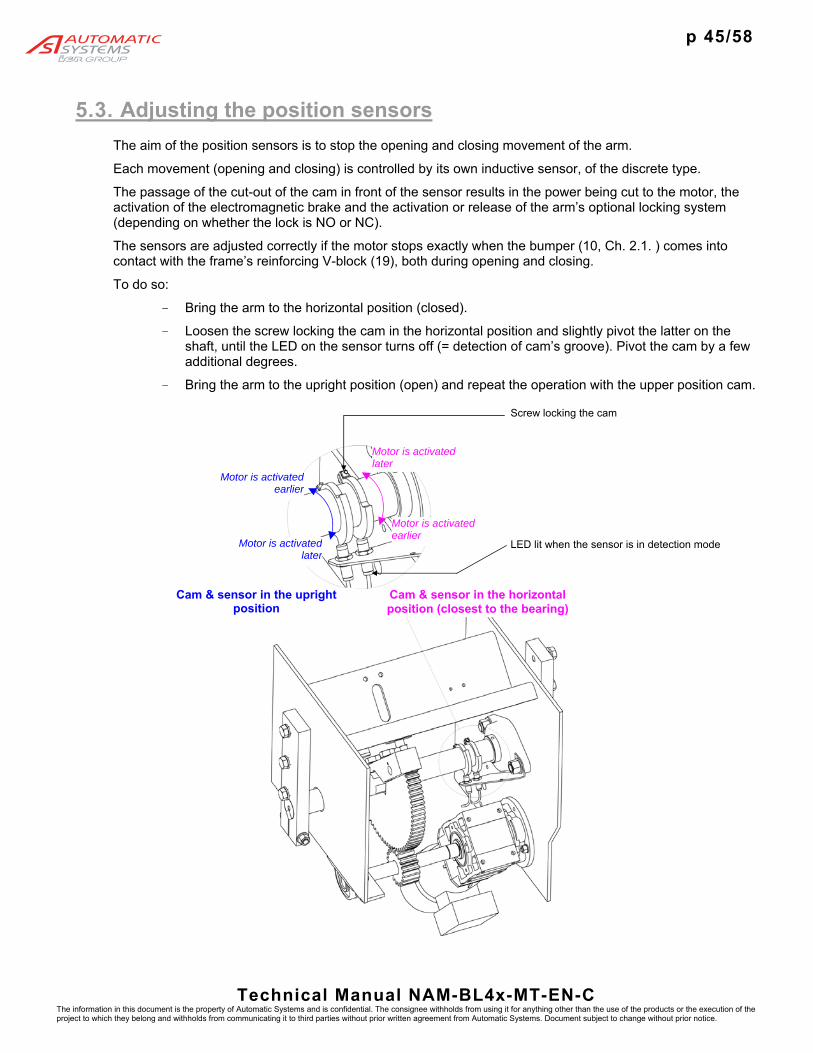
p 45/58
Technical Manual NAM-BL4x-MT-EN-C The information in this document is the property of Automatic Systems and is confidential. The consignee withholds from using it for anything other than the use of the products or the execution of the project to which they belong and withholds from communicating it to third parties without prior written agreement from Automatic Systems. Document subject to change without prior notice.
5.3. Adjusting the position sensors
The aim of the position sensors is to stop the opening and closing movement of the arm.
Each movement (opening and closing) is controlled by its own inductive sensor, of the discrete type.
The passage of the cut-out of the cam in front of the sensor results in the power being cut to the motor, the activation of the electromagnetic brake and the activation or release of the arm’s optional locking system (depending on whether the lock is NO or NC).
The sensors are adjusted correctly if the motor stops exactly when the bumper (10, Ch. 2.1. ) comes into contact with the frame’s reinforcing V-block (19), both during opening and closing.
To do so:
- Bring the arm to the horizontal position (closed).
- Loosen the screw locking the cam in the horizontal position and slightly pivot the latter on the shaft, until the LED on the sensor turns off (= detection of cam’s groove). Pivot the cam by a few additional degrees.
- Bring the arm to the upright position (open) and repeat the operation with the upper position cam.
Motor is activatedearlier
Motor is activatedlater
Motor is activated earlier
Motor is activated later
Cam & sensor in the horizontal position (closest to the bearing)
Cam & sensor in the upright position
Screw locking the cam
LED lit when the sensor is in detection mode

p 46/58
Technical Manual NAM-BL4x-MT-EN-C The information in this document is the property of Automatic Systems and is confidential. The consignee withholds from using it for anything other than the use of the products or the execution of the project to which they belong and withholds from communicating it to third parties without prior written agreement from Automatic Systems. Document subject to change without prior notice.
6. USE The barrier must be used in compliance with safety instructions (Ch. 1. ). Never operate the barrier without bumpers (10, Ch. 2.1. ), or without an arm.
6.1. First startup
1. Before startup, review the procedures described in Chapters 4. and 5.
2. Engage the circuit breaker (20).
3. If the barrier is equipped with heater turn on the heater circuit breaker (24).
4. On the control board:
- Select the menus language (left key ◄).
- Set all the parameters of the QUICK START menu.
- Make sure to save these modifications (QUICK START ► MEMORY ► Save).
5. Switch off the power supply network, wait 10 s and turn it on again.
6. Proceed to run a few electrical opening and closing tests by pressing the control board’s OK button or by means of the available command mode (push-button box, transmitter/receiver, etc.). Check that the arm is correctly positioned in the open (vertical) and closed (horizontal) positions. Refer to the corresponding adjustment where necessary (Ch. 4. and 5. ).
7. Check that the variable speed controller (17, Ch. 2.1.) shows a range of positive values when the obstacle opens and the negative values when it closes. If this is not the case, the motor is running in reverse and you must reverse 2 phases of the motor, after having turned off the circuit breaker (20).
8. Check that all the possible safeties and options are operating properly.
9. Proceed to maintenance (Ch. 6.5. ).
6.2. Daily startup Follow steps 1, 3, 5, 7 in Chapter 6.1.
6.3. Turning off the power Trip the circuit breaker (20). If the barrier is equipped with heater also turn off the heater circuit breaker (24).

p 47/58
Technical Manual NAM-BL4x-MT-EN-C The information in this document is the property of Automatic Systems and is confidential. The consignee withholds from using it for anything other than the use of the products or the execution of the project to which they belong and withholds from communicating it to third parties without prior written agreement from Automatic Systems. Document subject to change without prior notice.
6.4. Manual opening of the arm The procedure to be followed to lift the arm manually differs depending on the installed options, as summarised in the following table:
BL CONFIGURATION PROCEDURE
Without lifting of the arm
Without lock Cut the power (circuit breaker (20, Ch. 2.1. ) on OFF) Lift the arm manually.
With lock NO Cut the power (circuit breaker (20, Ch. 2.1. ) on OFF) Lift the arm manually.
With lock NC Cut the power (circuit breaker (20, Ch. 2.1. ) on OFF) Open the cover.
Spread the clips (83) to manually unlock the locking pin
(84) (see Ch. 2.3. ).
Lift the arm manually.
With automatic lifting of the arm
Without lock Cut the power (circuit breaker (20, Ch. 2.1. ) on OFF)
With lock NO Cut the power (circuit breaker (20, Ch. 2.1. ) on OFF)
With lock NC Cut the power (circuit breaker (20, Ch. 2.1. ) on OFF) Open the cover.
Spread the clips (83) to manually unlock the locking pin
(84) (see Ch. 2.3. ).
Lower the arm manually if in the up position. If the arm is in the down position it should lift by itself in the open position.

p 48/58
Technical Manual NAM-BL4x-MT-EN-C The information in this document is the property of Automatic Systems and is confidential. The consignee withholds from using it for anything other than the use of the products or the execution of the project to which they belong and withholds from communicating it to third parties without prior written agreement from Automatic Systems. Document subject to change without prior notice.
6.5. Maintenance
The indicators in this chapter refer to the illustrations in Ch. 2.1.
Never operate the barrier without bumpers (10, Ch. 2.1. ), even manually!
Maintenance activities must be carried out in compliance with the safety warnings listed in Chapter 1.
Unlock and remove the lateral and front doors (3) without damaging the ground wire that connects them to the housing. Cut the circuit breaker (20 & 24).
Remove the cover (1) without damaging the ground wire that links it to the housing.
After the first 1,000 operations
· Check the adjustment of the limit switches (Ch. 5.3. ).
Every 6 months
· Visually check the position of the arm: Check whether the arm is properly vertical and horizontal
and that it does not bounce. If not, check whether the position sensors (7) are properly adjusted and whether the rubber bumpers (10) are damaged.
· Check the adjustments described in Chapter 5. · Clean the exterior of the housing and the arm using a soft rag impregnated with a mild detergent.
For countries with a lot of sun, we recommend treating the exterior of the housing with polish. · Perform an audio check of the rotation of the bearings. · Unlock the arm if the barrier is equipped with mechanical locking system by spreading the clip (83) · Open the arm manually. It should be easy to lift and lower the arm. · Test the automatic lifting of the arm, by cutting the power (models with automatic lifting).
Every year · Check that the fastenings are tightened properly (torque): bearings, gear motor, hub, sensors,
spring assembly(ies), fastening of the arm, fastening to the ground, etc. · Inspection of the condition of the electrical connections. · Lubrication, using an anticorrosive multipurpose grease:
· Gears (11 + 15) · Upper bearing(s) of the spring assembly (42) · Spring guide rods (25 + 33)
· Lubricate using a liquid lubricant · Lower part (in contact with the plate) of the clips (83) of the arm’s locking system (Ch 2.3. ).
Note: The bearings (4) and gear motor (9) are lubricated for their entire service life. Simply check their tightness (absence of leaks).
Every 2 years
· Check tightness of the barrier’s base plate. · Check the state of cleanliness inside the barrier.

p 49/58
Technical Manual NAM-BL4x-MT-EN-C The information in this document is the property of Automatic Systems and is confidential. The consignee withholds from using it for anything other than the use of the products or the execution of the project to which they belong and withholds from communicating it to third parties without prior written agreement from Automatic Systems. Document subject to change without prior notice.
6.6. Troubleshooting
SYMPTOM CAUSE APPROPRIATE SOLUTIONS
The barrier stays open
Open command is given continually
Check that the open command is a pulse and not a continual command.
The loop sensor (optional) remains engaged
Review the sensor’s sensitivity adjustment and reset the loop sensor to zero. Adjusting the sensitivity adjustment to a setting that is too high may lead to locking in the open position.
Check the condition of the LEDs on the detector to see whether it and/or the loop are in good condition.
The cell (optional) sends information that something is present
Check the alignment of the cells.
Check that the cells are not dirty.
The barrier stays locked, or locks during movement
The variable speed controller is defective
See the list of defects regarding the variable speed controller.
The limit switch sensor provides incorrect information (see Ch.5.3. )
In the horizontal position: ensure that the horizontal position sensor is the only one to be in the cam’s cut-out and that it is operational and connected correctly.
In the upright position: ensure that the upright position sensor is the only one to be in the cam’s cut-out and that it is operational and connected correctly.
The barrier stays locked and the display on the control board is off
Power supply
Check the power supply at the general power supply box.
Check the current voltage at the entry of the cable to the general circuit breaker (20, Ch. 2.1. ), and ensure that the latter is engaged (circuit breaker at ON).
Check the command connections in accordance with the wiring diagram as well as the correct tightening of all electrical cables and tighten, where necessary.
Check the condition of the two fuses on the control board.
If the 5 green LEDs near the LCD are lit, check whether the control board is in programming mode (cable RJ45 is connected).
The barrier stays locked, but the control board display is lit
Short circuit on the external communication terminal block
Check whether the red LEDs near the LCD (other than analogue output) are lit.
- If not, switch off the mains supply and remove the terminal blocks (on the AS1320 and AS1321 if present). Switch the power back on and check again whether the red LEDs are lit. If this is the case, a short circuit is present in the terminal blocks. In order to reactivate the outputs, the control board has to be turned on again.
- If so, see the defects displayed (PRDSTD – BL_xxx menu Log/ Close status/Open status).

p 50/58
Technical Manual NAM-BL4x-MT-EN-C The information in this document is the property of Automatic Systems and is confidential. The consignee withholds from using it for anything other than the use of the products or the execution of the project to which they belong and withholds from communicating it to third parties without prior written agreement from Automatic Systems. Document subject to change without prior notice.
The barrier closes a long time after the vehicle has passed
Closing time delay after passage is too long
Check the values of the time delays (extended menus).
The barrier opens by itself.
The opening loop (optional) is too sensitive.
Adjust the sensitivity and/or frequency of the opening sensor. Adjusting the sensitivity adjustment to a setting that is too high or incorrect frequency can lead to untimely openings.
The access control system gives untimely orders.
Inspect it.
The barrier opens and closes immediately afterwards.
The barrier is not stable and during opening the signal from the cell (optional) is no longer aligned.
Properly secure the barrier to the ground.
The barrier bounces in upright and in horizontal position
Too much stress on the rubber bumpers inside the barrier.
Adjust the position sensors (Ch. 5.3. ).
The mains power turns off when the barrier is switched on.
The leakage breaker is not adapted.
Use a 300 mA leakage breaker for up to three barriers and for cases requiring a 30 mA system, use a SI type circuit breaker (Super-Immunised) for each barrier.

p 51/58
Technical Manual NAM-BL4x-MT-EN-C The information in this document is the property of Automatic Systems and is confidential. The consignee withholds from using it for anything other than the use of the products or the execution of the project to which they belong and withholds from communicating it to third parties without prior written agreement from Automatic Systems. Document subject to change without prior notice.
7. TECHNICAL SPECIFICATIONS
Electrical power supply: 120V~ (± 10%)/60Hz
Nominal Power consumed: 450 W
Ambient operating temperature: -20°C to +50°C [-4°F to 122°F]
(-25°C [-13°F] with optional 250W heater
(-45°C [-49°F] with optional 500W heater)
Average relative humidity: 95% without condensation
Maximum wind speed (without disrupting the operation): 120km/h [74.6 mi/h]
Protection index: IP44
Net weight (without arm): 220 kg (BL40) 230 kg (BL41) 250 kg (BL43) 250 kg (BL46)
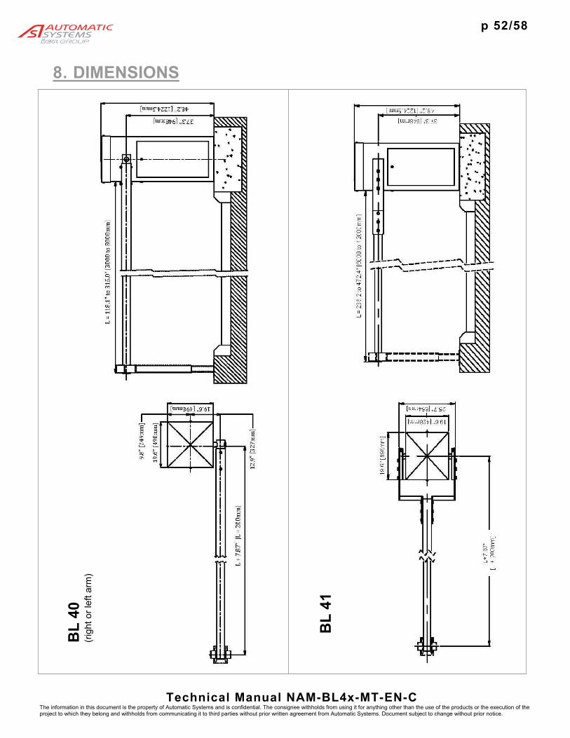
p 52/58
Technical Manual NAM-BL4x-MT-EN-C The information in this document is the property of Automatic Systems and is confidential. The consignee withholds from using it for anything other than the use of the products or the execution of the project to which they belong and withholds from communicating it to third parties without prior written agreement from Automatic Systems. Document subject to change without prior notice.
8. DIMENSIONS
BL
40
(rig
ht o
r le
ft ar
m)
BL
41

p 53/58
Technical Manual NAM-BL4x-MT-EN-C The information in this document is the property of Automatic Systems and is confidential. The consignee withholds from using it for anything other than the use of the products or the execution of the project to which they belong and withholds from communicating it to third parties without prior written agreement from Automatic Systems. Document subject to change without prior notice.
BL
43
BL
46
(rig
ht o
r le
ft ar
m)
No
te: i
n op
en p
ositi
on, t
he fo
ldin
g fe
nce
is 1
0 m
m w
ider
than
the
hous
ing
(fre
e pa
ssag
e (L
) re
duce
d by
10
mm
)

p 54/58
Technical Manual NAM-BL4x-MT-EN-C The information in this document is the property of Automatic Systems and is confidential. The consignee withholds from using it for anything other than the use of the products or the execution of the project to which they belong and withholds from communicating it to third parties without prior written agreement from Automatic Systems. Document subject to change without prior notice.
9. WIRING DIAGRAMS Note: for information only. The reference diagram is inside the equipment
.

p 55/58
Technical Manual NAM-BL4x-MT-EN-C The information in this document is the property of Automatic Systems and is confidential. The consignee withholds from using it for anything other than the use of the products or the execution of the project to which they belong and withholds from communicating it to third parties without prior written agreement from Automatic Systems. Document subject to change without prior notice.
9.1. Control blocks assignment
Connector block number 1 2 3 4 5 6 7 8 9 10 11 12 13 14 15 16
Co
nn
ecto
rs
A
GN
D
GN
D
GN
D
GN
D
24V
24V
24V
GN
D
GN
D
GN
D
RE
L3
- O
utpu
t re
lay
3
RE
L3
+
Out
put
rela
y 3
GN
D
GN
D
GN
D
GN
D
B
AO
1
FI s
ettin
g
DO
11 P
WM
O
utpu
t 11
DO
8
Des
cend
ing
mot
or
24V
DI1
3
Clo
sing
LS
DI1
1
Lock
Clo
se C
MD
DI9
C
lose
com
man
d
24V
24 V
24V
RE
L2
- O
utpu
t re
lay
2
RE
L2
+
Out
put
rela
y 2
24V
24V
24V
24V
C
AI1
A
nalo
g. S
enso
r
DO
10sP
WM
O
utpu
t 10
DO
7
Ris
ing
mot
or
DI1
4
cra
nk
limit
switc
h
DI1
2
Ope
ning
LS
DI1
0
Lock
Ope
n C
MD
DI8
O
pen
com
man
d
DI7
S
top
com
man
d
DI6
R
eade
r A
com
man
d
DI5
S
win
g of
f sen
s./L
ock
RE
L1
- O
utpu
t re
lay
1
RE
L1
+
Out
put
rela
y 1
DI4
C
ell 4
DI3
C
ell 3
DI2
C
ell 2
DI1
C
ell 1
A In/Out B connector blocks. C
X13 Inductive loops X14 connectors.
X9 Connectors for X11 inductive loops
presence detectors.
Y Inductive loops presence detector.
A
B
C
1 2 3 4 5 6 ............................
X14
X11
DP1DP2
DP3DP4
Y
DP1
DP2
DP3
DP4
X13
X9

p 56/58
Technical Manual NAM-BL4x-MT-EN-C The information in this document is the property of Automatic Systems and is confidential. The consignee withholds from using it for anything other than the use of the products or the execution of the project to which they belong and withholds from communicating it to third parties without prior written agreement from Automatic Systems. Document subject to change without prior notice.
INPUTS
Signals from outside that are received by the control board. There is a green LED under every input connection, which indicates its status (ON/OFF).
DI1, DI2, DI3, DI4 (cell): signal from the optional safety cells (see “connecting the presence sensors” below).
DI5 (Swing off sens./Lock):
1. Swing off sensor: for all machines except BL4x, signal emitted by the optional arm swing off detector when it no longer detects the arm on the jaw. Also, configure the Arm Swing Off parameter in the OPTIONS menu.
2. Lock: for BL4x, signal emitted by the arm locking device sensor, indicating the status of the lock (locked or unlocked).
DI6 (reader A command): order to open from the optional badge reader.
DI7 (stop command): order to stop the movement of the obstacle immediately, from a push-button box, remote control, etc. Also, see the Stop CMD parameter in the OPTIONS menu.
DI8 (open CMD): order to open the obstacle, from a push-button box, remote control, reader, etc. Also, configure the Exploitation parameter in the QUICK START menu.
DI9 (close CMD): order to close the obstacle, from a push-button box, remote control, etc. Also, see the Exploitation parameter in the QUICK START menu.
DI10 (lock open CMD): order to keep the obstacle in the open position, from an external switch.
DI11 (lock close CMD): order to keep the obstacle in the closed position, from an external switch.
DI12 (Sw open): signal from the opening limit-switch detector.
DI13 (Sw close): signal from the closing limit-switch detector.
DI14 (crank limit switch): signal from the presence detector switch of the crank used for manual operation of the obstacle (only on some types of equipment). This turns off the motor command outputs (DO7 and DO8) to prevent the obstacle from moving while the crank is engaged (safety). If there is no crank limit switch on the equipment, connections B4 and C4 must be linked.
AI1 (analogue sensor): analogue signal from the analogue position sensor, which must be activated (Positioning parameter under the QUICK START menu).
OUTPUTS
Signals sent by the control board to external elements. There is a red LED under every output connection, which indicates its status (ON/OFF).
REL1- and REL1+: connectors of the relay (assignment is adjustable via the OUTPUT FUNCTION menu).
REL2- and REL2+: connectors of the relay (assignment is adjustable via the OUTPUT FUNCTION menu).
REL3- and REL3+: connectors of the relay (assignment is adjustable via the OUTPUT FUNCTION menu).
DO7 (rising motor): status 1 (ON) if the obstacle is opening or completely open.
DO8 (descending motor): status 1(ON) if the obstacle is closing or completely closed.
(DO9 = Power relay 1 (cf. OUTPUT FUNCTION menu) on X8 connector)
DO10 PWM and DO11 PWM (Pulse Width Modulation): power element outputs (for arm lighting, flashing light, frequency inverter fan) adjustable via the OUTPUT FUNCTION menu: outputs 10 and 11.
AO1 (FI setting): analogue signal sent to the frequency inverter controlling the speed of the motor.
CONNECTORS FOR EXTERNAL ELEMENTS
24V: 24 Volt DC connector.
GND: 0 Volt connector.

p 57/58
Technical Manual NAM-BL4x-MT-EN-C The information in this document is the property of Automatic Systems and is confidential. The consignee withholds from using it for anything other than the use of the products or the execution of the project to which they belong and withholds from communicating it to third parties without prior written agreement from Automatic Systems. Document subject to change without prior notice.
Connecting the presence sensors
The board accepts up to four Presence Sensors (cells and/or loops, the generic term used in the rest of the manual and on the plans, diagrams and display is PS).
The cells are directly connected to connectors A, B and C (positions 13 to 16).
The loops are connected to the X13 connectors (loop x on connector DPx) (cable sections 2.5 mm²) and the associated detector (Y) is connected to the corresponding pin (Z). Note 1: a double detector allows the handling of 2 loops simultaneously, but only following 2 combinations: either DP1 & DP2, either DP3 & DP4.
Note 2: circuits DP1, DP2, DP3, DP4 of connector X13 are respectively linked to circuits DP1, DP2, DP3, DP4 of connectors A, B and C. A loop and a cell may not be put on the same circuit (in other words, if a cell is connected to DI1 (connector 16), a loop may not be at DP1 but may be at DP2, 3 or 4).
Note 3: it is also necessary to configure the Exploitation parameter in the QUICK START menu.
Warning: when the presence sensors are put in place, the obstacle may move. Hence, the presence sensors should not be placed before power to the equipment has been cut (circuit breaker off).
Connecting the heating resistance (option)
The optional heating resistance is feed by the circuit breaker 24, It is directly controlled by thermostat E.
24
E

p 58/58
Technical Manual NAM-BL4x-MT-EN-C The information in this document is the property of Automatic Systems and is confidential. The consignee withholds from using it for anything other than the use of the products or the execution of the project to which they belong and withholds from communicating it to third parties without prior written agreement from Automatic Systems. Document subject to change without prior notice.
Technical Support for North America Automatic Systems
T: 1 800 263.6548 ext 233 - F: 450.659.0966
www.automatic-systems.com


![QUICK MENU [4] DISABLE CANCEL QUICK MENU [1] THU CH5 …konics.co.kr/upload/data/KRN100_KEP-K-0121_20150416_W.pdf · quick menu [3] quick menu [1] quick menu [4] disable cancel quick](https://img.dokumen.tips/doc/110x75/5a9da0aa7f8b9a21688d17b5/quick-menu-4-disable-cancel-quick-menu-1-thu-ch5-menu-3-quick-menu-1.jpg)