Embed Size (px)
Citation preview

http://syaifulsipil96.blogspot.com/ [email protected]
14 - 1
14.1 INTRODUCTION Composite structure is a structural member composed of two materials, steel and reinforced concrete structure. Because it is composed of two materials the strength of composite structure is
provided by strength of the steel and strength of reinforced concrete. In steel construction the
composite structure is a composite beam and composite column. Composite beam consist of
reinforced concrete slab with steel beam and connected with shear connector. Composite column
is steel column cased in reinforced concrete column or steel column encase reinforced concrete
column.
This chapter describes the analysis and design procedure of composite structure such as composite
beam, composite column and composite beam-column. The design of composite beam with formed
steel deck and design shear connector also described.
14.2 BEHAVIOR OF COMPOSITE STRUCTURE 14.2.1 GENERAL The classically design method of steel structure is assume that steel beam is carry the load
independently. But with the advent of welding method we can provide the mechanical shear connector
to ensure that the steel beam can act together with the reinforced concrete slab to carry the load.
14.2.2 ADVANTAGES & DISADVANTAGES
The use of composite structure has both advantages and disadvantages. The advantages and
disadvantages of composite structure is involve the structural aspect and also the economical aspect.
The advantages of the composite structure are :
Shallower steel beam so the weight of steel is reduced (20% - 30%).
Increased on floor stiffness.
Increased of span length.
The disadvantages of the composite structure are :
Increased of the long term deflection.
Use of temporary shoring.
14.2.3 COMPOSITE ACTION
The composite action is developed when the load is carried by two structural materials act as one unit. In the case of composite beam the load is carry by reinforced concrete slab together with steel
CHAPTER
14 ANALYSIS AND DESIGN OF COMPOSITE STRUCTURE

http://syaifulsipil96.blogspot.com/ [email protected]
14 - 2
beam. To ensure the two structural materials can acts compositely we must ensure that there is no slip
between the materials. To prevent the slip between two materials the mechanical shear connector usually used. When the composite action is can be developed the strength of composite structure is
provided by strength of reinforced concrete and strength of steel.
14.2.4 SHORED & UN-SHORED CONSTRUCTION
Until the concrete has cured there is no composite action can be developed so the weight of the slab
must be resisted by other temporary structure. After the concrete has cured the composite action is
possible.
There are two general method of construction of composite structure, as follows :
Shored Construction, in shored construction the temporary shoring is used to support the wet
concrete so no steel beam is carries the wet concrete load. After the concrete is cured the
temporary shoring will removed and the load is carry by the composite of steel beam and
reinforced concrete slab.
Un-Shored Construction, in un-shored construction the wet concrete is carried by the steel beam.
After the concrete is cured the load is carried by the composite of steel beam and reinforced
concrete slab. The steel beam must be designed during the construction and during the
services.
Although the use of temporary shoring will be reduced the steel beam section but it will cause
additional cost for the temporary shoring. The effect steel beam reduction is not so economic compared
with the temporary shoring cost.
14.3 PROPERTIES OF COMPOSITE STRUCTURE 14.3.1 GENERAL Because the composite structure is composed of two materials we need to find the properties of
combined materials that can be analyzed as one unit of structure. The major properties we need to
calculate are the effective width of the reinforced concrete slab and elastic stress distribution of composite structure.
14.3.2 EFFECTIVE WIDTH
The concept of effective width of reinforced concrete slab is similar as in the ACI code but with some
simplification by AISC – LRFD code. As already know that the effective width of reinforced concrete
slab is used only in positive flexure moment and for negative moment is neglected because the
slab is in tension. Actually the stress distribution at the slab is not uniform and converted becomes
uniform stress over the effective width.
The effective width of reinforced concrete slab is taken as the smallest of :
TABLE 14.1 EFFECTIVE WIDTH INTERIOR GIRDER EXTERIOR GIRDER
4LbE ≤ edgeE b
8Lb +≤

http://syaifulsipil96.blogspot.com/ [email protected]
14 - 3
0E bb ≤ edge0E bb
21b +≤
where :
bE = effective width
L = beam span length
b0 = center to center bema spacing
bedge = distance of edge beam center to edge of slab
For non-uniform beam spacing the half of effective width (left or right side from the beam center)can be taken as :
TABLE 14.2 EFFECTIVE WIDTH – NON-UNIFORM BEAM SPACING INTERIOR GIRDER EXTERIOR GIRDER
8Lb 1E ≤
01E b21b ≤
edgeE b8Lb +≤
edge0E bb21b +≤
FIGURE 14.1 EFFECTIVE WIDTH
14.3.3 ELASTIC STRESS DISTRIBUTION
Before the ultimate strength design is explained it is very important to know the elastic stress
distribution of the non-homogen materials that is the composite material. The elastic stress distribution
is needed if the composite action is cannot be developed because of the limitation of width
thickness ratio is exceeded.
Based on the basic engineering mechanics the stress distribution formula is only can be used for the
homogen material, as follows :
IMcfb =
ItQSfv =
[14.1]
where :
fb = elastic bending stress
fv = elastic shear stress

http://syaifulsipil96.blogspot.com/ [email protected]
14 - 4
For the composite material the equation above cannot used anymore, we must modified the composite
section becomes transformed section. The transformed section method transforms the concrete material into an amount of steel that has the same effect as the concrete.
The method of transformed section requires the strain in the steel is the same as the concrete strain already replaced.
The strain of the steel and the replacement concrete is :
s
s
c
csc E
fEf
=⇒ε=ε
ccc
ss nff
EEf ==
[14.2]
where :
n = modular ratio
The equation above means the steel stress fs is similar as n times of the concrete stress fc.
If the equation is written in area of steel and concrete becomes :
⎟⎟⎠
⎞⎜⎜⎝
⎛=
cs APn
AP
nAA c
s = [14.3]
So the required steel area that replaces the concrete is area of concrete divide by the modular ratio
n. in composite structure usually done by divide the effective width of reinforced concrete slab by
the modular ratio n and the slab thickness is still the same.
The figure below shows the transformed area of the composite structure using a transformed
section method.
FIGURE 14.2 TRANSFORMED SECTION

http://syaifulsipil96.blogspot.com/ [email protected]
14 - 5
The elastic stress distribution at the steel is calculated as follows :
tr
stst I
Myf =
tr
sbsb I
Myf = [14.4]
where :
fst = steel stress at top fiber
fsb = steel stress at bottom fiber
M = elastic flexure moment
yst = distance of top fiber of steel from the neutral axis
ysb = distance of bottom fiber of steel from the neutral axis
Itr = moment of inertia of the transformed section about the neutral axis
The elastic stress distribution at concrete is :
tr
ctc nI
Myf = [14.5]
where :
fc = concrete stress
yct = distance of top fiber of concrete from the neutral axis
n = modular ratio
Itr = moment of inertia of the transformed section about the neutral axis
The location of neutral axis is calculated based on the transformed section, as follows :
The area of transformed concrete is tn
bE ⎟⎠
⎞⎜⎝
⎛
The area of steel section is still the same as original.
The moment of inertia is calculated also for the transformed section about the neutral axis of
the transformed section.
The figure below shows the comparison of the elastic stress distribution of actual composite section
and the transformed section.
FIGURE 14.3 ELASTIC STRESS DISTRIBUTION

http://syaifulsipil96.blogspot.com/ [email protected]
14 - 6
14.4 ANALYSIS OF COMPOSITE BEAM – ELASTIC STRESS 14.4.1 GENERAL
The flexural strength of composite beam is depended to the width thickness ratio of the beam web.
It is depend on the compact section or non-compact section category. The limitation of width
thickness ratio of beam web is similar as in rolled beam limitation.
The flexural strength of the composite beam is determined based on the elastic stress distribution at
the first yield of the steel if the beam web is non-compact, as follows :
TABLE 14.3 NON-COMPACT COMPOSITE BEAM ksi MPa
yw F640
th
> yw F
E76.3th
>
where :
h = height of web
tw = thickness of web
E = modulus of elasticity
Fy = yield strength
14.4.2 FLEXURAL STRENGTH The flexural strength of non-compact composite beam is determined based on elastic stress
distribution at the first yield of the steel. The reason is if the web is slender the steel beam
cannot provide full plastic strength due to the ultimate load. As previously explained the elastic
stress distribution is using the transformed section method.
The elastic section modulus of the transformed section for the extreme compression fiber and
extreme tension fiber is :
ct
trct y
IS =
sb
trsb y
IS = [14.6]
where :
Sct = elastic section modulus of extreme concrete compression fiber
Ssb = elastic section modulus of extreme steel tension fiber
Itr = moment of inertia of transformed section
yct = distance of top fiber of concrete from the neutral axis
ysb = distance of bottom fiber of steel from the neutral axis
The nominal flexural strength of non-compact steel beam is :
sbyn SFM =
( )nnB M90.0M =φ [14.7]

http://syaifulsipil96.blogspot.com/ [email protected]
14 - 7
14.5 ANALYSIS OF COMPOSITE BEAM – PLASTIC STRESS 14.5.1 GENERAL
As previously explained that the flexural strength of composite beam depend to the width thickness
ratio of the beam web.
The flexural strength of the composite beam is determined based on the plastic stress distribution if
the beam web is compact, as follows :
TABLE 14.4 COMPACT COMPOSITE BEAM ksi MPa
yw F640
th
≤ yw F
E76.3th
≤
where :
h = height of web
tw = thickness of web
E = modulus of elasticity
Fy = yield strength
To calculate the flexural strength based on the plastic stress distribution we must compute first the
location of plastic neutral axis (PNA). The location of PNA may be in the reinforced concrete slab or
in the steel. The analysis is using the Whitney rectangular stress distribution (ACI code) of the
concrete and yield strength of the steel.
14.5.2 PLASTIC NEUTRAL AXIS IN RC SLAB
When the PNA lies in the slab the analysis is similar as in reinforced concrete with singly reinforced
beam.
FIGURE 14.4 PNA IN RC SLAB
The resultant of compressive force of the concrete slab is :
Ec ab'f85.0C = [14.8]

http://syaifulsipil96.blogspot.com/ [email protected]
14 - 8
The resultant of tensile force of the steel beam is :
ysFAT = [14.9]
where :
C = resultant of compressive force of concrete
f’c = cylinder concrete compressive strength
a = depth of concrete compressive block
bE = effective flange width
T = resultant of tensile force of steel beam
As = area of steel beam
Fy = yield strength of steel beam
And the static horizontal equilibrium of the resultant force is :
∑ =⇒= TC0H
ysEc FAab'f85.0 =
Ec
ys
b'f85.0FA
a = [14.10]
The nominal flexural strength of the composite beam is :
⎟⎠
⎞⎜⎝
⎛ −+==2at
2dab'f85.0CdM sEc1n
⎟⎠
⎞⎜⎝
⎛−+==
2at
2dFATdM sys1n
[14.11]
The design flexural strength is :
( )nnB M85.0M =φ [14.12]
This condition which is the PNA is on the RC slab means that the concrete slab is capable to
developing in compression the full nominal strength of the steel beam in tension. It called as slab
adequate condition.
The PNA is in the RC slab if follows the condition below, as follows :
ysEsc FAbt'f85.0 ≥ [14.13]
14.5.3 PLASTIC NEUTRAL AXIS IN STEEL BEAM
If the depth of compressive concrete block a is exceed the slab thickness then the location of PNA is in
the steel beam.

http://syaifulsipil96.blogspot.com/ [email protected]
14 - 9
FIGURE 14.5 PNA IN STEEL BEAM
The resultant of compressive force of concrete is :
Escc bt'f85.0C = [14.14]
The static horizontal equilibrium of the resultant force is :
sc CCT +=
sys CFAT −= [14.15]
where :
T = resultant of tensile force of steel beam
Cc = resultant of compressive force of concrete
Cs = resultant of tensile force of steel beam
So the resultant of tensile force of steel beam is :
syssc CFACC −=+
2CFA
C cyss
−=
2bt'f85.0FA
C Escyss
−=
[14.16]
The nominal flexural strength of the composite beam is :
2s1cn dCdCM += [14.17]
The design flexural strength is :
( )nnB M85.0M =φ [14.18]
This condition which is the PNA is on the RC slab means that the concrete slab is not capable to
developing in compression the full nominal strength of the steel beam in tension.
The PNA is in the steel beam if follows the condition below, as follows :
ysEsc FAbt'f85.0 < [14.19]
http://syaifulsipil96.blogspot.com/ [email protected]
14 - 10
14.6 SHEAR STRENGTH 14.6.1 GENERAL
The shear strength of the composite beam is provided by the beam web without any contribution of
the reinforced concrete slab. So the analysis of shear strength is similar as in the rolled beam section.
14.7 SHEAR CONNECTOR 14.7.1 GENERAL Due to the flexure there will be horizontal shear force between the reinforced concrete slab and the
steel beam. The horizontal force is equal to the compressive force in the concrete C. To ensure the
fully composite action this force must be resisted so there is no slip between the concrete and the
steel beam. Usually a mechanical shear connector is used to ensure there is no sip between the
concrete and the steel beam.
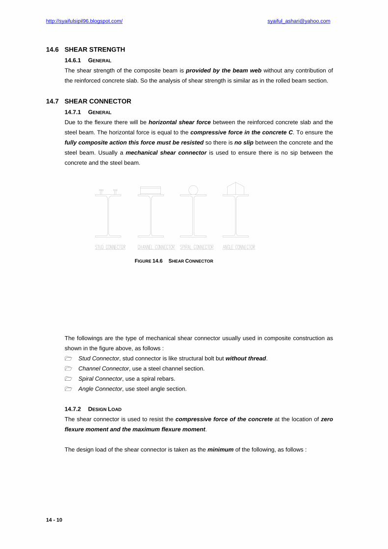
FIGURE 14.6 SHEAR CONNECTOR
The followings are the type of mechanical shear connector usually used in composite construction as
shown in the figure above, as follows :
Stud Connector, stud connector is like structural bolt but without thread.
Channel Connector, use a steel channel section.
Spiral Connector, use a spiral rebars.
Angle Connector, use steel angle section.
14.7.2 DESIGN LOAD
The shear connector is used to resist the compressive force of the concrete at the location of zero
flexure moment and the maximum flexure moment.
The design load of the shear connector is taken as the minimum of the following, as follows :

http://syaifulsipil96.blogspot.com/ [email protected]
14 - 11
TABLE 14.5 DESIGN LOAD OF SHEAR CONNECTOR POSITIVE MOMENT
REGION NEGATIVE MOMENT
REGION ACTION CONDITION
sEch tb'f85.0V = – FULLY COMPOSITE REQUIRED
ysh FAV = y1sh FAV = FULLY COMPOSITE REQUIRED
∑ nQ ∑ nQ PARTIAL COMPOSITE PROVIDED
where :
Vh = horizontal shear force between the concrete and steel beam
Qn = nominal strength of one shear connector
As1 = area of compression reinforcement
The fully composite action assume there is no slip between the concrete and steel beam, partial
composite action assume there is slip between the concrete and steel beam.
14.7.3 STUD SHEAR CONNECTOR
The nominal strength of one stud shear connector embedded in solid concrete slab is :
uscccscn FAE'fA5.0Q ≤= [14.20]
where :
Qn = nominal strength of one stud shear connector
Asc = section area of stud connector
f’c = cylinder compressive strength of concrete
Ec = modulus of elasticity of concrete
Fu = tensile strength of stud connector
There is no resistance factor used in calculation of shear connector strength.
14.7.4 CHANNEL SHEAR CONNECTOR
The nominal strength of channel shear connector embedded in solid concrete slab is :
( ) cccwfn E'fLt5.0t3.0Q += [14.21]
where :
Qn = nominal strength of channel shear connector
tf = flange thickness of channel shear connector
tw = web thickness of channel shear connector
f’c = cylinder compressive strength of concrete
Ec = modulus of elasticity of concrete
There is no resistance factor used in calculation of shear connector strength.

http://syaifulsipil96.blogspot.com/ [email protected]
14 - 12
14.7.5 NUMBER The number of shear connector required between the zero moment to maximum moment is :
n
h1 Q
VN = [14.22]
where :
N1 = number of shear connector
Vh = horizontal shear force
Qn = nominal strength of one shear connector
The number of shear connector must be distributed uniformly within the length they are
required. 14.7.6 PLACEMENT The shear connector is placed between adjacent zero moment and maximum moment and
distributed uniformly.
FIGURE 14.7 SHEAR CONNECTOR FOR SIMPLE BEAM
For simple beam structure the number of shear connector N1 is distributed uniformly at the L/2
length. So for full span we need 2N1 shear connector.
FIGURE 14.8 SHEAR CONNECTOR FOR SIMPLE BEAM WITH P LOAD
For simple beam structure with concentrated load the number of shear connector N1 is distributed
uniformly between the zero moment and maximum moment. The additional shear connector N2
is required between zero moment and moment due to concentrated load.

http://syaifulsipil96.blogspot.com/ [email protected]
14 - 13
FIGURE 14.9 SHEAR CONNECTOR FOR CONTINUOUS BEAM
For continuous beam structure the number of shear connector N1 is distributed uniformly between the zero moment and maximum moment and also between maximum moment and inflection
point.
At the negative moment region there is no composite action so theoretically it is not efficient to use shear connector in this region. The composite action is only provided by the longitudinal
reinforcement and the steel beam.
14.7.7 SIZE & LIMITATION The followings are the limitation of stud shear connector, as follows :
Maximum stud diameter is 2.5 x flange thickness of the steel section.
Minimum length is 4 x stud diameter.
Minimum longitudinal spacing is 6 x stud diameter.
Maximum longitudinal spacing is 8 x slab thickness.
Minimum transverse spacing is 4 x stud diameter.
Minimum concrete cover is 1 inch.
The following is the standard size of stud connector from the AWS Structural Code (1996) and
minimum length limits from AISC, as follows :
TABLE 14.6 STUD SHEAR CONNECTOR
φ
(inch)
L (inch)
½ 2 5/8 2 ½
¾ 3 7/8 3 ½
1 4
14.8 COMPOSITE BEAM WITH FORM STEEL DECK 14.7.8 GENERAL Usually the form steel deck is used in many of floor slab and left in place as integral of the structure.
The form steel deck consists of ribs that can be perpendicular or parallel to the supporting beam.
The major function of the form steel deck is to provide lateral support before the concrete is cured.

http://syaifulsipil96.blogspot.com/ [email protected]
14 - 14
The following is the basic assumption of the analysis of composite beam with form steel deck, as
follows :
If the rib is perpendicular to supporting beam the concrete below the top of deck is neglected
in the calculation of section properties and Ac.
If the rib is parallel to supporting beam the concrete below the top of deck may be included in the calculation of section properties and Ac.
The capacity of the shear connector is reduced.
Fully composite action usually cannot be developed because the limitation of the number of
shear connector required. The partial composite action will govern for the composite bema
with form steel deck.
FIGURE 14.10 FORM STEEL DECK
14.7.9 REDUCED CAPACITY OF SHEAR CONNECTOR Based on the test the strength of shear connector must be reduced when the rib is perpendicular to
the supporting beam.
The reduction factor for shear connector for rib perpendicular with beam is :
0.10.1hH
hw
N85.0
r
s
r
r
r≤
⎥⎥⎦
⎤
⎢⎢⎣
⎡−⎟⎟
⎠
⎞⎜⎜⎝
⎛⎟⎟⎠
⎞⎜⎜⎝
⎛ [14.23]
where :
Nr = number of stud per rib (maximum 3)
wr = average width of rib
hr = height of rib
Hs = length of stud
The length of stud must not exceed the following value (although the actual length is greater), as
follows :
mm75hH rs += [14.24]

http://syaifulsipil96.blogspot.com/ [email protected]
14 - 15
FIGURE 14.11 DETERMINATION OF NR
FIGURE 14.12 RIB DIMENSION
The reduction factor for shear connector for rib parallel with beam is :
0.10.1hH
hw60.0
r
s
r
r ≤⎥⎥⎦
⎤
⎢⎢⎣
⎡−⎟⎟
⎠
⎞⎜⎜⎝
⎛⎟⎟⎠
⎞⎜⎜⎝
⎛ [14.25]
14.7.10 PARTIAL COMPOSITE ACTION
Partial composite action is a composite action when there are not enough shear connector to
prevent slip between the concrete and the steel beam. The reason is the limitation of maximum
number of shear connector cannot be achieved because limited by rib spacing. In partial composite
action the full strength of the concrete and steel beam cannot fully develop. If the required number of
the shear connector cannot be provided to produce full composite action then we must provide the
shear connector less than the actual number. The total of shear connector strength ΣQn then
used as resultant of compressive force when calculate the composite beam strength. In partial
composite action the plastic neutral axis (PNA) will usually fall within the steel cross section.
The moment of inertia of the partial composite section is :
( )strf
nseff II
CQII −∑+= [14.26]
where :
Ieff = effective moment of inertia
Is = moment of inertia of steel section
Cf = resultant of compressive force for fully composite action
Itr = moment of inertia for fully composite action

http://syaifulsipil96.blogspot.com/ [email protected]
14 - 16
The resultant of compressive force must be taken as the minimum of :
ysFA
sEc tb'f85.0
∑ nQ [14.27]
Partial composite action occurs when the ∑ nQ is governs.
FIGURE 14.13 PARTIAL COMPOSITE ACTION
The figure above shows the internal force diagram for partial composite action.
The horizontal shear force between the concrete and steel beam is Vh which is equal to :
∑= nh QV [14.28]
Then the horizontal shear force Vh must equal to concrete compressive force Cc, form this
relationship we can find the depth of compressive block, as follows :
hc VC =
hEc Vab'f85.0 =
Ec
hb'f85.0
Va = [14.29]
The location of PNA can be find by maintain the following static horizontal equilibrium, as follows :
0VCT hs =−− [14.30]
The nominal flexure moment can be compute by take sum of moment at the tensile force resultant,
as follows :
( ) ( )2s1cn dCdCM += [14.31]
To find the location of PNA is in the flange or below the flange the following equation can be used to
check, as follows :
The resultant of compressive force at the flange is :
yffyf FtbP = [14.32]

http://syaifulsipil96.blogspot.com/ [email protected]
14 - 17
The net force transmitted at the interface between the concrete and steel beam is :
yfh PT'V −=
( ) yfyfysh PPFA'V −−= [14.33]
The PNA is in the flange if follows the condition below :
hh V'V < [14.34]
To find the location of PNA in the flange the following relationship is used, as follows :
( ) yfyfysh F'tbF'tbFAV −−= [14.35]
14.7.11 LIMITATION
The following are the limitation of composite beam structure with form steel deck, as follows :
Maximum rib height is 3 inch.
Minimum average width of rib is 2 inch.
Minimum slab thickness above top of deck is 2 inch.
Maximum stud diameter is ¾ inch.
Minimum height of stud above the top of deck is 1 ½ inch.
Maximum longitudinal spacing is 36 inch.
14.9 COMPOSITE COLUMN 14.7.12 GENERAL The analysis of composite column is similar as in ordinary steel column but there is some modification
of parameters. The parameters to be modified are Fy, E and r to match the experimental result with
theoretical result.
14.7.13 BASIC AXIAL STRENGTH
The axial strength of composite column if the stability is ensured is :
ccyrrysn A'f85.0FAFAP ++= [14.36]
where :
Pn = nominal axial strength
As = area of steel section
Ar = total area of longitudinal reinforcement
Ac = area of the concrete
Fy = yield strength of steel section
Fyr = yield strength of longitudinal reinforcement
If the equation above is divide with the area of steel section becomes :
⎟⎟⎠
⎞⎜⎜⎝
⎛+⎟⎟
⎠
⎞⎜⎜⎝
⎛+==
s
cc
s
ryrymy
s
nAA'f85.0
AAFFF
AP [14.37]

http://syaifulsipil96.blogspot.com/ [email protected]
14 - 18
14.7.14 MODIFY FMY – LRFD REQUIREMENT
The modify Fmy according to LRFD code is :
⎟⎟⎠
⎞⎜⎜⎝
⎛+⎟⎟
⎠
⎞⎜⎜⎝
⎛+=
s
cc2
s
ryr1ymy A
A'fcAAFcFF [14.38]
where :
Fmy = modify Fy
Fy = yield strength of steel section
Fyr = yield strength of longitudinal reinforcement
As = area of steel section
Ar = total area of longitudinal reinforcement
Ac = area of the concrete
The constant of c1 and c2 is depend to the type of composite column, as follows :
TABLE 14.7 CONSTANT C1 AND C2 TYPE C1 C2
PIPE & TUBE 1.0 0.85
ENCASED SHAPE 0.7 0.60
14.7.15 MODIFY EM – LRFD REQUIREMENT
The modify Em according to LRFD code is :
⎟⎟⎠
⎞⎜⎜⎝
⎛+=
s
cc3sm A
AEcEE [14.39]
where :
Em = modify E
Es = modulus of elasticity of steel section
Ec = modulus of elasticity of concrete
As = area of steel section
Ar = total area of longitudinal reinforcement
Ac = area of the concrete
The constant of c3 is depend to the type of composite column, as follows :
TABLE 14.8 CONSTANT C3 TYPE C3
PIPE & TUBE 0.40
ENCASED SHAPE 0.20

http://syaifulsipil96.blogspot.com/ [email protected]
14 - 19
14.7.16 MODIFY RM – LRFD REQUIREMENT
The modify rm according to LRFD code is :
b3.0rr sm ≥= [14.40]
where :
rm = modify r
rs = radius of gyration of steel section
b = dimension of concrete in plane of buckling
Conservative approach of modify rm is use the larger of the radius of gyration of steel section and the
radius of gyration of concrete.
14.7.17 AXIAL STRENGTH The axial strength of composite column is similar as in the axial strength of steel column but the
calculation is using the modification parameters.
14.7.18 LIMITATION
The following are the limitation of composite column, as follows :
The structural steel at least 4% of the total area or the behavior is as reinforced concrete column.
For enchased section
Longitudinal reinforcements must be used. Load carrying bars must be continuous at framed
levels.
Lateral reinforcement must be used. Spacing of ties must not exceed 2/3 of least lateral column
dimension.
Area of longitudinal and lateral reinforcement at least 0.18 mm2 per m of bar spacing.
Minimum of cover is 38 mm.
Concrete class
For normal concrete the concrete class is MPa55'fMPa21 c ≤≤
For light weight concrete the concrete class is MPa28'f c ≥
Structural steel and reinforcement bars grade
The yield strength is MPa380Fy ≤
Minimum wall thickness of concrete fill pipe or tube
For rectangular section s
y
E3F
bt ≥
For circular section s
y
E8F
Dt ≥
http://syaifulsipil96.blogspot.com/ [email protected]
14 - 20
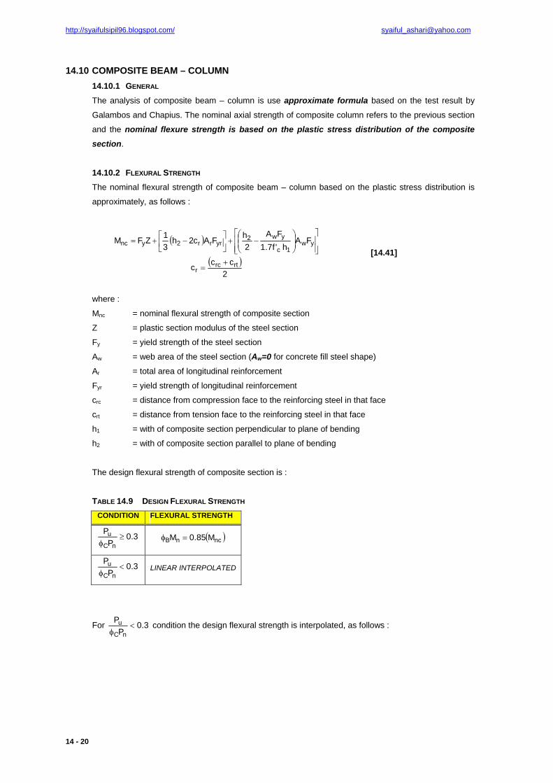
14.10 COMPOSITE BEAM – COLUMN 14.10.1 GENERAL
The analysis of composite beam – column is use approximate formula based on the test result by
Galambos and Chapius. The nominal axial strength of composite column refers to the previous section
and the nominal flexure strength is based on the plastic stress distribution of the composite
section.
14.10.2 FLEXURAL STRENGTH The nominal flexural strength of composite beam – column based on the plastic stress distribution is
approximately, as follows :
( )⎥⎥⎦
⎤
⎢⎢⎣
⎡⎟⎟⎠
⎞⎜⎜⎝
⎛−+⎥
⎦
⎤⎢⎣
⎡ −+= yw1c
yw2yrrr2ync FA
h'f7.1FA
2hFAc2h
31ZFM
( )2
ccc rtrcr
+=
[14.41]
where :
Mnc = nominal flexural strength of composite section
Z = plastic section modulus of the steel section
Fy = yield strength of the steel section
Aw = web area of the steel section (Aw=0 for concrete fill steel shape)
Ar = total area of longitudinal reinforcement
Fyr = yield strength of longitudinal reinforcement
crc = distance from compression face to the reinforcing steel in that face
crt = distance from tension face to the reinforcing steel in that face
h1 = with of composite section perpendicular to plane of bending
h2 = with of composite section parallel to plane of bending
The design flexural strength of composite section is :
TABLE 14.9 DESIGN FLEXURAL STRENGTH CONDITION FLEXURAL STRENGTH
3.0P
P
nC
u ≥φ
( )ncnB M85.0M =φ
3.0P
P
nC
u <φ
LINEAR INTERPOLATED
For 3.0P
P
nC
u <φ
condition the design flexural strength is interpolated, as follows :

http://syaifulsipil96.blogspot.com/ [email protected]
14 - 21
FIGURE 14.14 FLEXURAL STRENGTH OF COMPOSITE SECTION
ZF9.0M ynBB =φ [14.42]
where :
Z = plastic section modulus of the steel section
Fy = yield strength of the steel section