Embed Size (px)
Citation preview
8/13/2019 BITS WASE ComputerGraphics Session 2 & 3
http://slidepdf.com/reader/full/bits-wase-computergraphics-session-2-3 1/72
Sessions – 2 and 3
Raster Graphics Algorithms forDrawing 2D objects: Lines, Circle,
Ellipse, Polygon & Filled Closed
Objects (Chap. 3.1 - 3.9)
Course Delivered by
Dr. K. Satyanarayan ReddyText Book
“Computer Graphics: Principles and Practice in C” by James D. Foley, A.Van Dam, S.K. Feiner, and J.F. Hughes,, 2nd edition Pearson Education.

8/13/2019 BITS WASE ComputerGraphics Session 2 & 3
http://slidepdf.com/reader/full/bits-wase-computergraphics-session-2-3 2/72
Basic Raster Graphics Algorithms for drawing 2D Primitives
A Raster Graphics package approximates
mathematical primitives, described in
terms of vertices on a Cartesian grid, by
sets of pixels of the appropriateintensity of gray or color.
These pixels are stored as a bitmap or
pixmap in CPU memory or in a frame
buffer.
26 October 2013 BITS-WASE: Computer Graphics by Dr. K. Satyanrayan Reddy 2

8/13/2019 BITS WASE ComputerGraphics Session 2 & 3
http://slidepdf.com/reader/full/bits-wase-computergraphics-session-2-3 3/72
Implications of Display System Architecture
The fundamental conceptual model presents a graphics package as the system that
mediates between the application program (and its application data
structure/model) and the display hardware.
The package gives the application program a device independent interface to the
hardware, as shown in Fig. below, where SRGP’s procedures are partitioned into
those forming an output pipeline and those forming an input pipeline.
26 October 2013 BITS-WASE: Computer Graphics by Dr. K. Satyanrayan Reddy 3
Clipping SRGP primitives to a rectangular clip region. (a) Primitives and clipping rectangle. (b) Clipped
results.

8/13/2019 BITS WASE ComputerGraphics Session 2 & 3
http://slidepdf.com/reader/full/bits-wase-computergraphics-session-2-3 4/72
In the Output Pipeline, the application program takes descriptions of
objects in terms of primitives (points, lines….) and attributesstored in or derived from an application model or data structure
and specifies them to the graphics package, which in turn clips and
scan converts them to the pixels to be seen on the screen.
The packages primitives generation procedures specify what
is to be generated,
the attribute procedures specify how primitives are to be
generated,
the SRGP_copy·Pixel procedure specifies how images are to
be modified, and
the canvas-control procedures specify where the images are
to be generated.
26 October 2013 BITS-WASE: Computer Graphics by Dr. K. Satyanrayan Reddy 4
Implications of Display System Architecture cont’d….

8/13/2019 BITS WASE ComputerGraphics Session 2 & 3
http://slidepdf.com/reader/full/bits-wase-computergraphics-session-2-3 5/72
In the Input Pipeline, a user interaction at the display end is converted to measure
values returned by the packages sampling or event driven input procedures to
the application program; it typically uses those values to modify the model or
the image on the screen.
Procedures relating to input include those to initialize and control input devices and
those to obtain the latter's measures during interaction.
26 October 2013 BITS-WASE: Computer Graphics by Dr. K. Satyanrayan Reddy 5
SRGP as intermediary between the Application Program and the Graphics System providing
output and input pipelines.
Implications of Display System Architecture cont’d….
8/13/2019 BITS WASE ComputerGraphics Session 2 & 3
http://slidepdf.com/reader/full/bits-wase-computergraphics-session-2-3 6/72
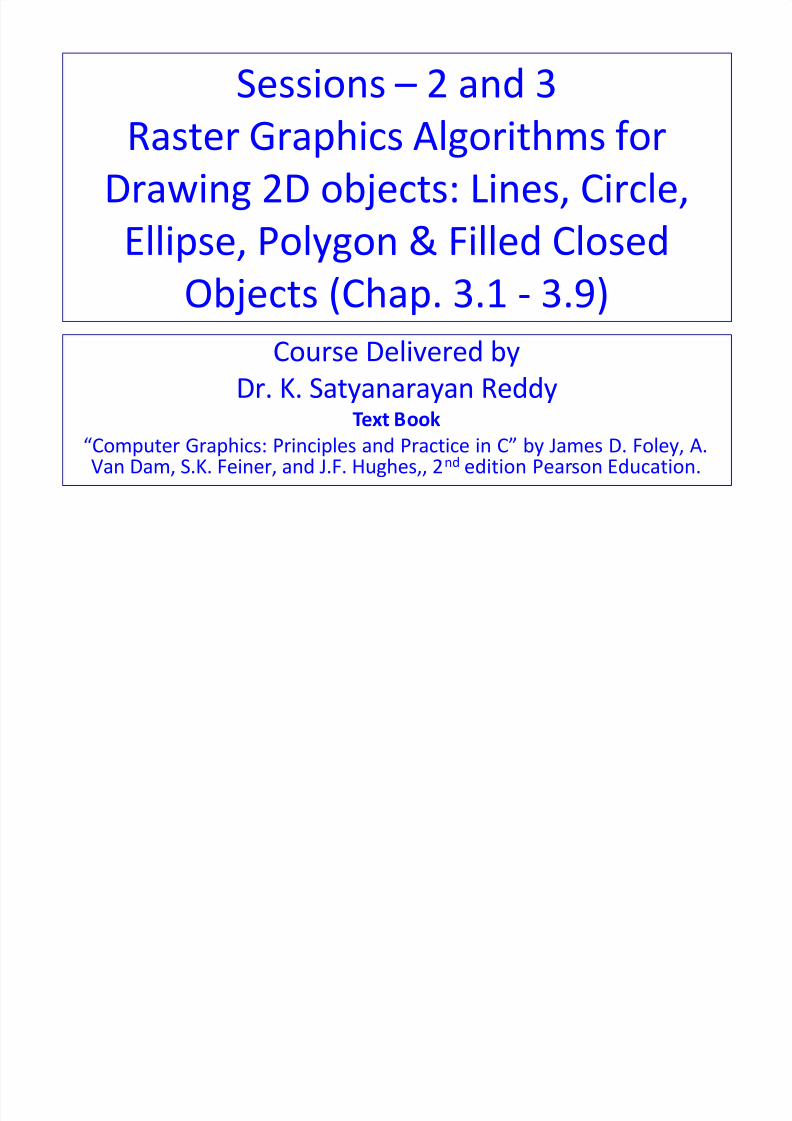
An SRGP implementation must communicate with a
wide variety of display devices.
These display controllers are processors specialized
to interpret and execute drawing commands that
generate pixels into the frame buffer.
Other, simpler systems are refreshed directly from
the memory used by the CPU.
Output-only subsets of the package may drive rasterhardcopy devices.
26 October 2013 BITS-WASE: Computer Graphics by Dr. K. Satyanrayan Reddy 6
Implications of Display System Architecture cont’d….
8/13/2019 BITS WASE ComputerGraphics Session 2 & 3
http://slidepdf.com/reader/full/bits-wase-computergraphics-session-2-3 7/72
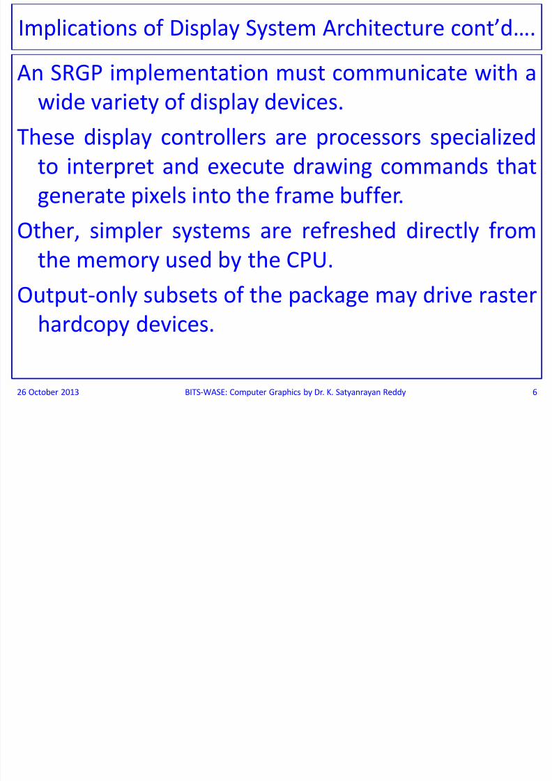
Displays with Frame Buffers and Display Controllers
SRGP has the least amount of work to do if it drives
a display controller that does its own scanconversion and handles all of SRGP’s primitives
and attributes directly.
The SRGP needs only to convert its internalrepresentation of primitives, attributes, and write
modes to the formats accepted by the display
peripheral that actually draws the primitives.
26 October 2013 BITS-WASE: Computer Graphics by Dr. K. Satyanrayan Reddy 7

8/13/2019 BITS WASE ComputerGraphics Session 2 & 3
http://slidepdf.com/reader/full/bits-wase-computergraphics-session-2-3 8/72
The Display Controller architecture allowing memory mapping tothe CPU to access the frame buffer directly and the displaycontroller to access the CPU’s memory.
The CPU can then read and write individual pixels and copyPixelblocks of pixels with normal CPU instructions, and the DisplayController can scan convert into offscreen canvases and also use
its copyPixel instruction to move pixels between the twomemories or within its own frame buffer.
When the CPU and the Display Controller can run asynchronously,there must be synchronization to avoid memory conflicts.
The package then uses the Display Controller for scan conversioninto the screen canvas but must do its own software scanconversion for offscreen canvases.
The package can copyPixel images scan converted by thehardware from the frame buffer to offscreen canvases.
26 October 2013 BITS-WASE: Computer Graphics by Dr. K. Satyanrayan Reddy 8
Displays with Frame Buffers and Display Controllers
cont’d….
8/13/2019 BITS WASE ComputerGraphics Session 2 & 3
http://slidepdf.com/reader/full/bits-wase-computergraphics-session-2-3 9/72
26 October 2013 BITS-WASE: Computer Graphics by Dr. K. Satyanrayan Reddy 9
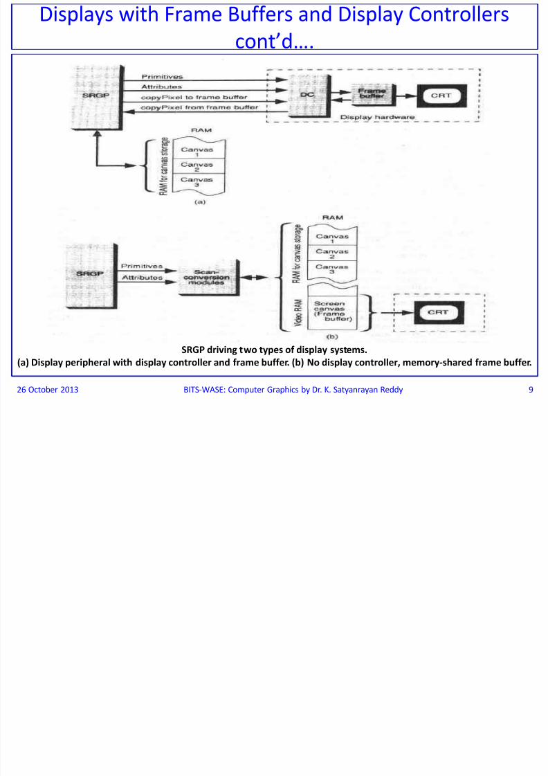
SRGP driving two types of display systems.
(a) Display peripheral with display controller and frame buffer. (b) No display controller, memory-shared frame buffer.
Displays with Frame Buffers and Display Controllers
cont’d….

8/13/2019 BITS WASE ComputerGraphics Session 2 & 3
http://slidepdf.com/reader/full/bits-wase-computergraphics-session-2-3 10/72
Displays with Frame Buffers only
For displays without a Display Controller, SRGP does
its own scan conversion into both offscreen
canvases and the frame buffer.
A typical organization for such an SRGP
implementation that drives a shared-memory
frame buffer is shown in above Fig. part (b).
Note: Only the parts of memory that constitute the
frame buffer and store the canvases managed bySRGP; the rest of the memory is occupied by all
the usual software and data, including SRGP itself.
26 October 2013 BITS-WASE: Computer Graphics by Dr. K. Satyanrayan Reddy 10

8/13/2019 BITS WASE ComputerGraphics Session 2 & 3
http://slidepdf.com/reader/full/bits-wase-computergraphics-session-2-3 11/72
Hardcopy DevicesThe simplest Hardcopy devices accept only one scan line at a
time and rely on the software to provide that scan line exactlywhen it is to be imaged on film or on paper.
The SRGP must generate a complete bitmap or pixmap and scan
it out one line at a time to the output device, Slightly smarter
devices can accept an entire frame (page) at a time.The more powerful equipment has built-in scan-conversion
hardware, often called Raster Image Processors (RIPs).
At the high end of the scale, PostScript printers have internal
"engines" that read PostScript programs describing pages in a
device-independent fashion; they interpret such programs to
produce the primitives and attributes that are then scan
converted.26 October 2013 BITS-WASE: Computer Graphics by Dr. K. Satyanrayan Reddy 11

8/13/2019 BITS WASE ComputerGraphics Session 2 & 3
http://slidepdf.com/reader/full/bits-wase-computergraphics-session-2-3 12/72
The Output Pipeline in SoftwareAs each output primitive is encountered by SRGP, the Package Scan converts
the primitive, Pixels are written in the current canvas according to their
applicable attributes and current write mode.
The primitive is also clipped to the clip rectangle i.e. Pixels belonging to the
primitive that are outside the clip region are not displayed. There are
several ways of clipping.
Clip a primitive prior to scan conversion by computing its analyticalintersections with the clip-rectangle boundaries; these intersection
points are then used to define new vertices for the clipped version of the
primitive.
The advantage of clipping before scan converting is that the Scan Converter
must deal with only the clipped version of the primitive, not with the
original one.
This technique is used most often for clipping lines, rectangles, and
polygons, for which clipping algorithms are fairly simple and efficient.
26 October 2013 BITS-WASE: Computer Graphics by Dr. K. Satyanrayan Reddy 12

8/13/2019 BITS WASE ComputerGraphics Session 2 & 3
http://slidepdf.com/reader/full/bits-wase-computergraphics-session-2-3 13/72
The simplest, brute-force clipping technique, called SCISSORING, isto scan convert the entire primitive but to write only the visible
pixels in the clip rectangle region of the canvas. This is done bychecking each pixel’s coordinates against the (x, y) bounds ofthe rectangle before writing that pixel.
In the second type there is no need to check adjacent pixels on ascan line and clipping is achieved; if the bounds check can be
done quickly; this approach may actually be faster than firstclipping the primitive and then scan converting the resulting,clipped portions.
A third technique is to generate the entire collection of primitivesinto a temporary canvas and then to copyPixel only the contents
of the clip rectangle to the destination canvas.This approach wastes of both space and time, but is easy to
implement and is often used for text Data structures forminimizing this overhead.
26 October 2013 BITS-WASE: Computer Graphics by Dr. K. Satyanrayan Reddy 13
The Output Pipeline in Software cont’d….

8/13/2019 BITS WASE ComputerGraphics Session 2 & 3
http://slidepdf.com/reader/full/bits-wase-computergraphics-session-2-3 14/72
SCAN CONVERTING LINESA scan-conversion algorithm for lines computes the coordinates
of the pixels that lie on or near an ideal, infinitely thin straight
line imposed on a 2D raster grid.
Consider a 1-pixel-thick approximation to an ideal line for lines
with slopes between -1 and 1 inclusive, exactly 1 pixel should
be illuminated in each column; for lines with slopes outsidethis range, exactly 1 pixel should be illuminated in each row.
All lines should be drawn with constant brightness, independent
of length and orientation, and as rapidly as possible.
e.g.: The shape of the endpoint regions should be underprogrammer control to allow slanted, rounded, and
orthogonal corners.
26 October 2013 BITS-WASE: Computer Graphics by Dr. K. Satyanrayan Reddy 14

8/13/2019 BITS WASE ComputerGraphics Session 2 & 3
http://slidepdf.com/reader/full/bits-wase-computergraphics-session-2-3 15/72
Figure below shows a highly magnified view of a 1-pixel thick
line and of the ideal line that it approximates.The intensified pixels are shown as filled circles and the non-
intensified pixels arc shown as unfilled circles.
On an actual screen, the diameter of the roughly Circular pixel is
larger than the inter-pixel spacing, so the symbolicrepresentation exaggerates the discreteness of the pixels.
26 October 2013 BITS-WASE: Computer Graphics by Dr. K. Satyanrayan Reddy 15
A scan converted line
showing intensified pixels
as black circles
SCAN CONVERTING LINES Cont’d….

8/13/2019 BITS WASE ComputerGraphics Session 2 & 3
http://slidepdf.com/reader/full/bits-wase-computergraphics-session-2-3 16/72
The Basic Incremental AlgorithmThe method for scan conversion of lines is to compute the slope m = Δy/Δ x,
to increment x by 1 starting with the leftmost point, to calculate
yi = m . xi + B for each xi, and to intensify the pixel at (xi, Round(yi)), whereRound(yi) = Floor(0.5 + yi).
This computation selects the closest pixel i.e. the pixel whose distance tothe true line is smallest.
This brute force strategy is inefficient, however, because each iterationrequires a floating point (or binary fraction) multiplication, addition, and
invocation of Floor.The multiplication can be eliminated by noting that
yi+1 = m.xi+1+ B = m(xi + Δx) + B = yi + m. Δx and, if Δx = 1, then yi+1 = yi + m,
Thus, a unit change in x changes y by m, which is the slope of the line.
For all points (xi, yi) on the line, if xi+1 = xi + 1, then yi+1 = yi + m; i.e. thevalues of x and y are defined in terms of their previous values.
This is an incremental algorithm, at each step incremental calculations aremade based on the preceding step starting from (x0, y0) as initial point.
26 October 2013 BITS-WASE: Computer Graphics by Dr. K. Satyanrayan Reddy 16
= m. xi + B + m. Δx since m . xi + B = yi where -1 ≤ m ≤ 1

8/13/2019 BITS WASE ComputerGraphics Session 2 & 3
http://slidepdf.com/reader/full/bits-wase-computergraphics-session-2-3 17/72
26 October 2013 BITS-WASE: Computer Graphics by Dr. K. Satyanrayan Reddy 17
Incremental calculation of (xi, yi)
The Basic Incremental Algorithm cont’d….

8/13/2019 BITS WASE ComputerGraphics Session 2 & 3
http://slidepdf.com/reader/full/bits-wase-computergraphics-session-2-3 18/72
Bresenham’s Midpoint Line Algorithm
The drawbacks of procedure Line are that rounding y to
an integer takes time, and that the variables y and m
must be real or fractional binary because the slope is
a fraction.
26 October 2013 BITS-WASE: Computer Graphics by Dr. K. Satyanrayan Reddy
18
Bresenham developed a classic
algorithm & it is better as it uses
only integer arithmetic, thus
avoiding the Round function and
allows the calculation for (xi+1, yi+1)to be performed incrementally i.e.
by using the calculation already
done at (xi, yi).
A floating point version of this
algorithm can be applied to lines
with arbitrary algorithm Real
valued endpoint coordinates.
8/13/2019 BITS WASE ComputerGraphics Session 2 & 3
http://slidepdf.com/reader/full/bits-wase-computergraphics-session-2-3 19/72
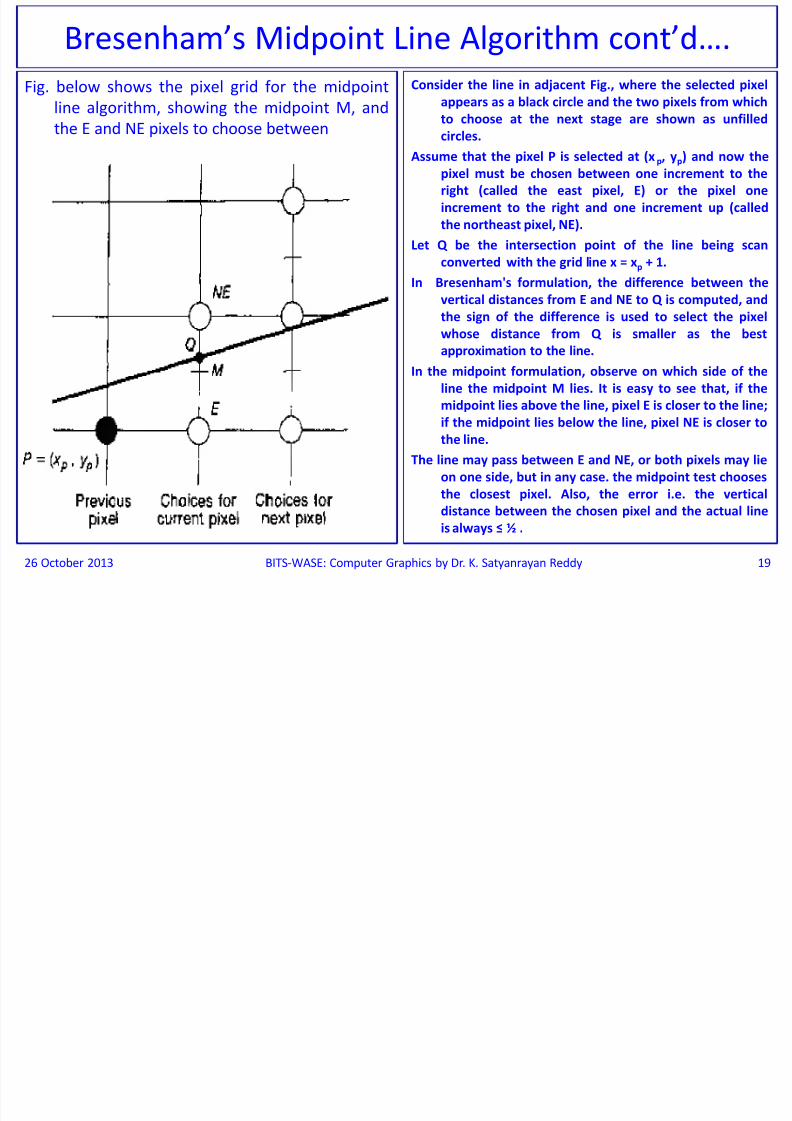
Fig. below shows the pixel grid for the midpoint
line algorithm, showing the midpoint M, and
the E and NE pixels to choose between
Consider the line in adjacent Fig., where the selected pixel
appears as a black circle and the two pixels from which
to choose at the next stage are shown as unfilled
circles.Assume that the pixel P is selected at (xp, yp) and now the
pixel must be chosen between one increment to the
right (called the east pixel, E) or the pixel one
increment to the right and one increment up (called
the northeast pixel, NE).
Let Q be the intersection point of the line being scan
converted with the grid line x = xp + 1.
In Bresenham's formulation, the difference between thevertical distances from E and NE to Q is computed, and
the sign of the difference is used to select the pixel
whose distance from Q is smaller as the best
approximation to the line.
In the midpoint formulation, observe on which side of the
line the midpoint M lies. It is easy to see that, if the
midpoint lies above the line, pixel E is closer to the line;
if the midpoint lies below the line, pixel NE is closer to
the line.
The line may pass between E and NE, or both pixels may lie
on one side, but in any case. the midpoint test chooses
the closest pixel. Also, the error i.e. the vertical
distance between the chosen pixel and the actual line
is always ≤ ½ .
26 October 2013 BITS-WASE: Computer Graphics by Dr. K. Satyanrayan Reddy 19
Bresenham’s Midpoint Line Algorithm cont’d….

8/13/2019 BITS WASE ComputerGraphics Session 2 & 3
http://slidepdf.com/reader/full/bits-wase-computergraphics-session-2-3 20/72
Midpoint (Bresenham) Line Drawing
26 October 2013 BITS-WASE: Computer Graphics by Dr. K. Satyanrayan Reddy 20
yP
xP
8/13/2019 BITS WASE ComputerGraphics Session 2 & 3
http://slidepdf.com/reader/full/bits-wase-computergraphics-session-2-3 21/72
Midpoint (Bresenham) Line Drawing cont’d….
26 October 2013 BITS-WASE: Computer Graphics by Dr. K. Satyanrayan Reddy 21
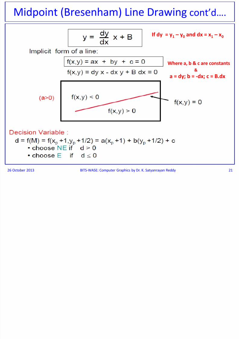
If dy = y1 – y0 and dx = x1 – x0
Where a, b & c are constants
a = dy; b = -dx; c = B.dx&

8/13/2019 BITS WASE ComputerGraphics Session 2 & 3
http://slidepdf.com/reader/full/bits-wase-computergraphics-session-2-3 22/72
26 October 2013 BITS-WASE: Computer Graphics by Dr. K. Satyanrayan Reddy 22
Midpoint (Bresenham) Line Drawing cont’d….
Where ΔE = dy
Where ΔNE = dy - dx

8/13/2019 BITS WASE ComputerGraphics Session 2 & 3
http://slidepdf.com/reader/full/bits-wase-computergraphics-session-2-3 23/72
26 October 2013 BITS-WASE: Computer Graphics by Dr. K. Satyanrayan Reddy 23
Midpoint (Bresenham) Line Drawing cont’d….

8/13/2019 BITS WASE ComputerGraphics Session 2 & 3
http://slidepdf.com/reader/full/bits-wase-computergraphics-session-2-3 24/72
26 October 2013 BITS-WASE: Computer Graphics by Dr. K. Satyanrayan Reddy 24
Midpoint (Bresenham) Line Drawing cont’d….

8/13/2019 BITS WASE ComputerGraphics Session 2 & 3
http://slidepdf.com/reader/full/bits-wase-computergraphics-session-2-3 25/72
Pseudo Code for Midpoint Line Drawing
26 October 2013 BITS-WASE: Computer Graphics by Dr. K. Satyanrayan Reddy 25
Use algorithm for the midpoint line from point
{5, 8} to point {9, 11} and draw the Line.

8/13/2019 BITS WASE ComputerGraphics Session 2 & 3
http://slidepdf.com/reader/full/bits-wase-computergraphics-session-2-3 26/72
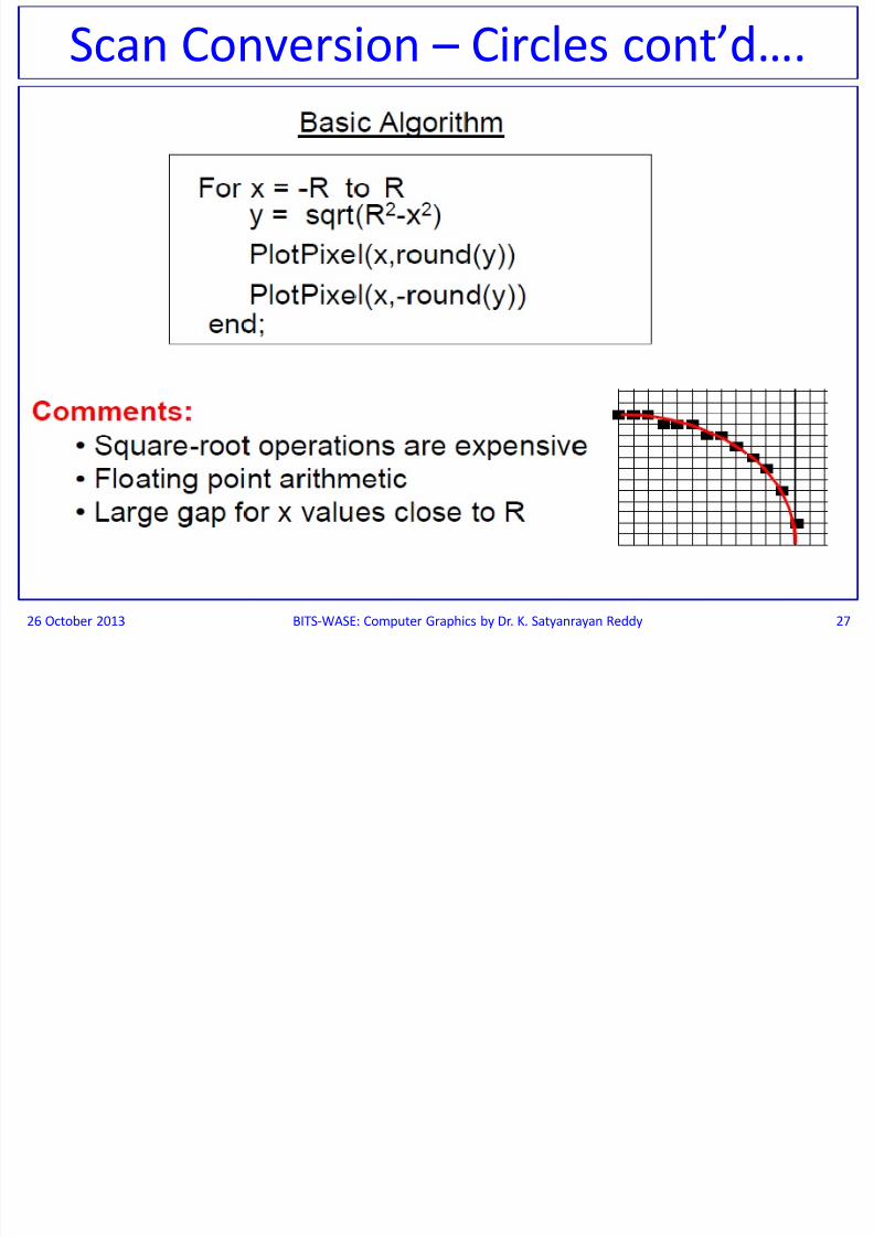
Scan Conversion - Circles
26 October 2013 BITS-WASE: Computer Graphics by Dr. K. Satyanrayan Reddy 26
8/13/2019 BITS WASE ComputerGraphics Session 2 & 3
http://slidepdf.com/reader/full/bits-wase-computergraphics-session-2-3 27/72
26 October 2013 BITS-WASE: Computer Graphics by Dr. K. Satyanrayan Reddy 27
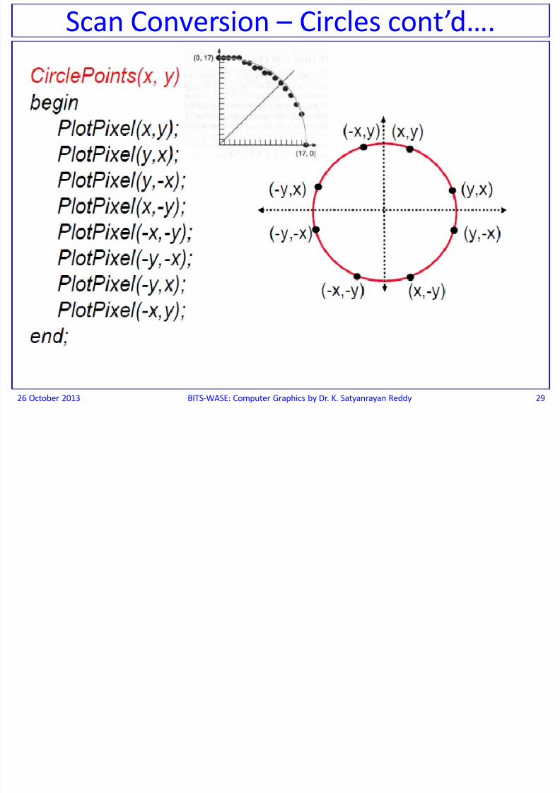
Scan Conversion – Circles cont’d….
S C i Ci l t’d

8/13/2019 BITS WASE ComputerGraphics Session 2 & 3
http://slidepdf.com/reader/full/bits-wase-computergraphics-session-2-3 28/72
26 October 2013 BITS-WASE: Computer Graphics by Dr. K. Satyanrayan Reddy 28
Scan Conversion – Circles cont’d….
S C i Ci l t’d
8/13/2019 BITS WASE ComputerGraphics Session 2 & 3
http://slidepdf.com/reader/full/bits-wase-computergraphics-session-2-3 29/72
26 October 2013 BITS-WASE: Computer Graphics by Dr. K. Satyanrayan Reddy 29
Scan Conversion – Circles cont’d….

8/13/2019 BITS WASE ComputerGraphics Session 2 & 3
http://slidepdf.com/reader/full/bits-wase-computergraphics-session-2-3 30/72
Midpoint Circle Algorithm
26 October 2013 BITS-WASE: Computer Graphics by Dr. K. Satyanrayan Reddy 30
8/13/2019 BITS WASE ComputerGraphics Session 2 & 3
http://slidepdf.com/reader/full/bits-wase-computergraphics-session-2-3 31/72
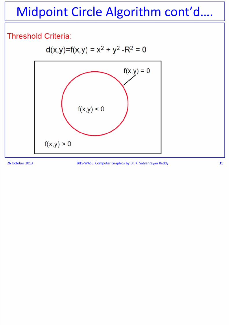
26 October 2013 BITS-WASE: Computer Graphics by Dr. K. Satyanrayan Reddy 31
Midpoint Circle Algorithm cont’d….

8/13/2019 BITS WASE ComputerGraphics Session 2 & 3
http://slidepdf.com/reader/full/bits-wase-computergraphics-session-2-3 32/72
26 October 2013 BITS-WASE: Computer Graphics by Dr. K. Satyanrayan Reddy 32
Midpoint Circle Algorithm cont’d….
8/13/2019 BITS WASE ComputerGraphics Session 2 & 3
http://slidepdf.com/reader/full/bits-wase-computergraphics-session-2-3 33/72
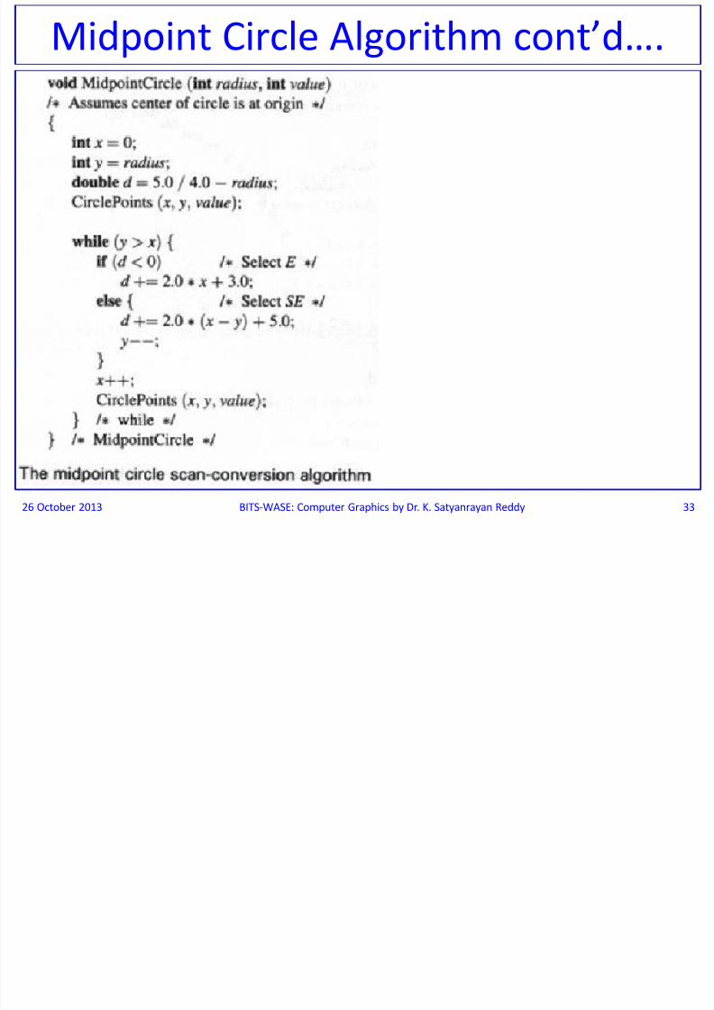
26 October 2013 BITS-WASE: Computer Graphics by Dr. K. Satyanrayan Reddy 33
Midpoint Circle Algorithm cont’d….
d d ff
8/13/2019 BITS WASE ComputerGraphics Session 2 & 3
http://slidepdf.com/reader/full/bits-wase-computergraphics-session-2-3 34/72
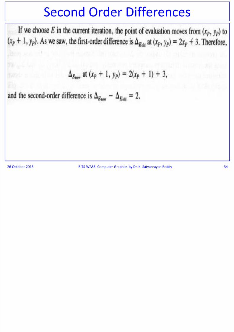
Second Order Differences
26 October 2013 BITS-WASE: Computer Graphics by Dr. K. Satyanrayan Reddy 34
d d ff ’d

8/13/2019 BITS WASE ComputerGraphics Session 2 & 3
http://slidepdf.com/reader/full/bits-wase-computergraphics-session-2-3 35/72
26 October 2013 BITS-WASE: Computer Graphics by Dr. K. Satyanrayan Reddy 35
Second Order Differences cont’d….
d d iff ’d

8/13/2019 BITS WASE ComputerGraphics Session 2 & 3
http://slidepdf.com/reader/full/bits-wase-computergraphics-session-2-3 36/72
26 October 2013 BITS-WASE: Computer Graphics by Dr. K. Satyanrayan Reddy 36
Second Order Differences cont’d….
S d O d Diff ’d
8/13/2019 BITS WASE ComputerGraphics Session 2 & 3
http://slidepdf.com/reader/full/bits-wase-computergraphics-session-2-3 37/72
26 October 2013 BITS-WASE: Computer Graphics by Dr. K. Satyanrayan Reddy 37
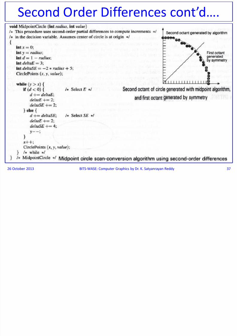
Second Order Differences cont’d….
S C i Elli

8/13/2019 BITS WASE ComputerGraphics Session 2 & 3
http://slidepdf.com/reader/full/bits-wase-computergraphics-session-2-3 38/72
Scan Converting Ellipses
26 October 2013 BITS-WASE: Computer Graphics by Dr. K. Satyanrayan Reddy 38
Equation of the Ellipse
S C i Elli ’d
8/13/2019 BITS WASE ComputerGraphics Session 2 & 3
http://slidepdf.com/reader/full/bits-wase-computergraphics-session-2-3 39/72
26 October 2013 BITS-WASE: Computer Graphics by Dr. K. Satyanrayan Reddy 39
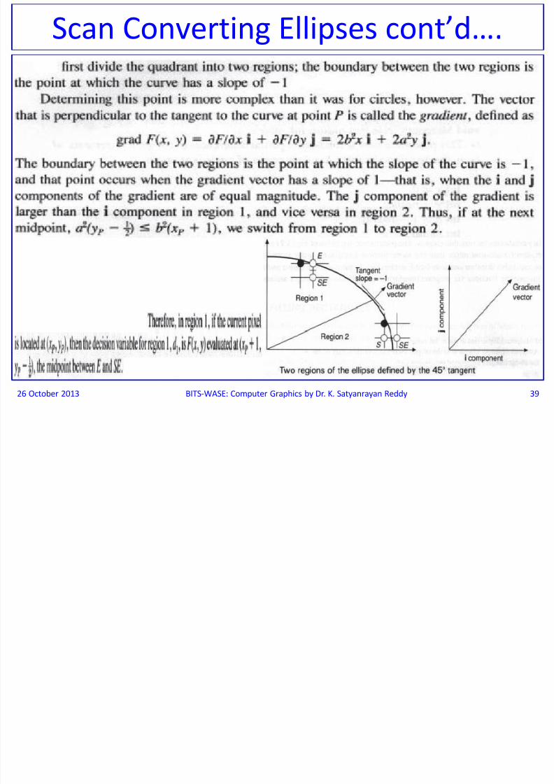
Scan Converting Ellipses cont’d….
S C ti Elli t’d
8/13/2019 BITS WASE ComputerGraphics Session 2 & 3
http://slidepdf.com/reader/full/bits-wase-computergraphics-session-2-3 40/72
26 October 2013 BITS-WASE: Computer Graphics by Dr. K. Satyanrayan Reddy 40
Scan Converting Ellipses cont’d….

8/13/2019 BITS WASE ComputerGraphics Session 2 & 3
http://slidepdf.com/reader/full/bits-wase-computergraphics-session-2-3 41/72
26 October 2013 Computer Graphics by Dr. K. Satyanrayan Reddy 41
FILLING RECTANGLES

8/13/2019 BITS WASE ComputerGraphics Session 2 & 3
http://slidepdf.com/reader/full/bits-wase-computergraphics-session-2-3 42/72
FILLING RECTANGLES
The task of filling primitives can be broken into two parts:
The decision of which pixels to fill (this depends onthe shape of the primitive, as modified by clipping), and
the easier decision of with what value to fill them.
To fill a rectangle with a solid color, each pixel is set to belying on a scan line running from the left edge to the right
edge to the same pixel value i.e. fill each span from xmin
to xmax.
26 October 2013 BITS-WASE: Computer Graphics by Dr. K. Satyanrayan Reddy 42
FILLING POLYGONS
8/13/2019 BITS WASE ComputerGraphics Session 2 & 3
http://slidepdf.com/reader/full/bits-wase-computergraphics-session-2-3 43/72
FILLING POLYGONS
26 October 2013 BITS-WASE: Computer Graphics by Dr. K. Satyanrayan Reddy 43
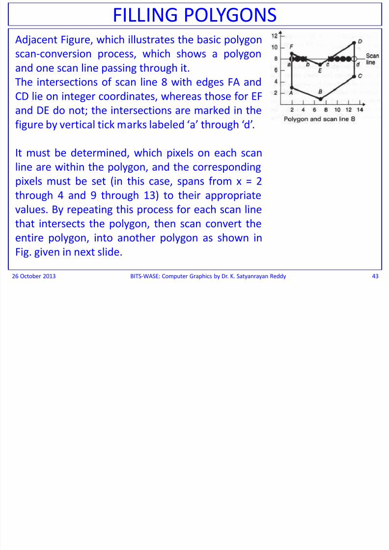
Adjacent Figure, which illustrates the basic polygon
scan-conversion process, which shows a polygon
and one scan line passing through it.The intersections of scan line 8 with edges FA and
CD lie on integer coordinates, whereas those for EF
and DE do not; the intersections are marked in the
figure by vertical tick marks labeled ‘a’ through ‘d’.
It must be determined, which pixels on each scan
line are within the polygon, and the corresponding
pixels must be set (in this case, spans from x = 2
through 4 and 9 through 13) to their appropriate
values. By repeating this process for each scan linethat intersects the polygon, then scan convert the
entire polygon, into another polygon as shown in
Fig. given in next slide.
FILLING POLYGONS cont’d

8/13/2019 BITS WASE ComputerGraphics Session 2 & 3
http://slidepdf.com/reader/full/bits-wase-computergraphics-session-2-3 44/72
26 October 2013 BITS-WASE: Computer Graphics by Dr. K. Satyanrayan Reddy 44
FILLING POLYGONS cont d…. In Fig. shown below; the Polygon, which was scan converted for another polygon.
Figure 3.23(a) shows the pixels defining the extrema of spans in black and the
interior pixels on the span in gray. A simple way of deriving the extrema is to usethe midpoint line scan-conversion algorithm on each edge and to keep a table of
span extrema for each scan line, updating an entry if a new pixel is produced for an
edge that extends the span.
FILLING POLYGONS cont’d

8/13/2019 BITS WASE ComputerGraphics Session 2 & 3
http://slidepdf.com/reader/full/bits-wase-computergraphics-session-2-3 45/72
The spans can be filled in by a 3 step process:
1. Find the intersections of the scan line with alledges of the polygon.
2. Sort the intersections by increasing ‘x’ coordinate.
3. Fill in all pixels between pairs of intersections thatlie interior to the polygon, using the odd parity
rule to determine that a point is inside a region:
Parity is initially even, and each intersection
encountered thus inverts the parity bit draw when
parity is odd, do not draw when it is even.
26 October 2013 BITS-WASE: Computer Graphics by Dr. K. Satyanrayan Reddy 45
FILLING POLYGONS cont d….
Horizontal Edges (To Draw)
8/13/2019 BITS WASE ComputerGraphics Session 2 & 3
http://slidepdf.com/reader/full/bits-wase-computergraphics-session-2-3 46/72
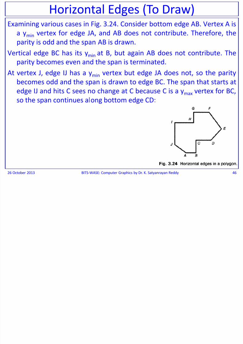
Horizontal Edges (To Draw)Examining various cases in Fig. 3.24. Consider bottom edge AB. Vertex A is
a ymin vertex for edge JA, and AB does not contribute. Therefore, the
parity is odd and the span AB is drawn.Vertical edge BC has its ymin at B, but again AB does not contribute. The
parity becomes even and the span is terminated.
At vertex J, edge IJ has a ymin vertex but edge JA does not, so the parity
becomes odd and the span is drawn to edge BC. The span that starts at
edge IJ and hits C sees no change at C because C is a ymax vertex for BC,
so the span continues along bottom edge CD;
26 October 2013 BITS-WASE: Computer Graphics by Dr. K. Satyanrayan Reddy 46
Horizontal Edges(To Draw) cont’d
8/13/2019 BITS WASE ComputerGraphics Session 2 & 3
http://slidepdf.com/reader/full/bits-wase-computergraphics-session-2-3 47/72
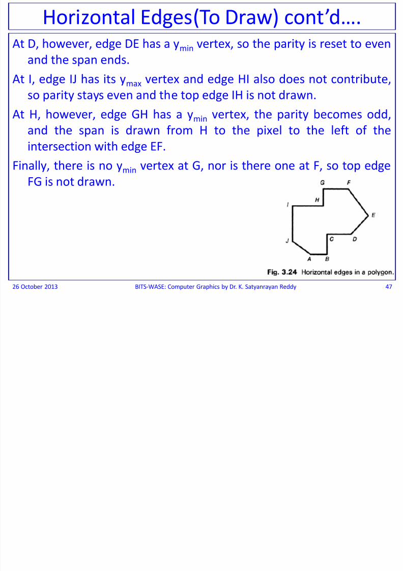
At D, however, edge DE has a ymin vertex, so the parity is reset to even
and the span ends.
At I, edge IJ has its ymax vertex and edge HI also does not contribute,
so parity stays even and the top edge IH is not drawn.
At H, however, edge GH has a ymin vertex, the parity becomes odd,
and the span is drawn from H to the pixel to the left of the
intersection with edge EF.
Finally, there is no ymin vertex at G, nor is there one at F, so top edge
FG is not drawn.
26 October 2013 BITS-WASE: Computer Graphics by Dr. K. Satyanrayan Reddy 47
Horizontal Edges(To Draw) cont d….
Slivers (To draw)

8/13/2019 BITS WASE ComputerGraphics Session 2 & 3
http://slidepdf.com/reader/full/bits-wase-computergraphics-session-2-3 48/72
Slivers (To draw)There is another problem with our Scan Conversion Algorithm that is not resolved
as satisfactorily as that of horizontal edges:
Consider, for example, the Triangle from (0, 0) to (3, 12) to (5, I2) to (0, O), shown in
Fig. below. Because of the rule that only pixels that lie interior or on a left or
bottom edge are drawn, there will be many scan lines with only a single pixel or
no pixels. The problem of having "missing" pixels is yet another example of the
aliasing problem; that is, of representing a continuous signal with a discrete
approximation.
26 October 2013 BITS-WASE: Computer Graphics by Dr. K. Satyanrayan Reddy 48
Slivers: Polygons with edges
that lie sufficiently close
together creating a Sliver
which is “a polygonal area so
thin that its interior does notcontain a distinct span for
each scan line”.
Edge Coherence and the Scan Line Algorithm

8/13/2019 BITS WASE ComputerGraphics Session 2 & 3
http://slidepdf.com/reader/full/bits-wase-computergraphics-session-2-3 49/72
Edge Coherence and the Scan Line Algorithm
Step 1: This procedure for calculating intersections; the bruteforce technique of testing each polygon edge forintersection with each new scan line must be avoided.
Very often, only a few of the edges are of interest for a givenscan line.
Also many edges intersected by scan line “i” are alsointersected by scan line “i + 1”.
This edge coherence occurs along an edge for as many scanlines as they intersect with the edge.
While moving from one scan line to the next, new ‘x’ intersection of the edge can be computed the on the basis
of the old ‘x’ intersection, by usingxi+1 = xi + 1/m,
where ‘m’ is the slope of the edge.
26 October 2013 BITS-WASE: Computer Graphics by Dr. K. Satyanrayan Reddy 49
Edge Coherence and the Scan Line Algorithm cont’d

8/13/2019 BITS WASE ComputerGraphics Session 2 & 3
http://slidepdf.com/reader/full/bits-wase-computergraphics-session-2-3 50/72
Consider lines with a slope greater than ‘+1’ that are
left edges; right edges and other slopes are handledby similar, and vertical edges are the special cases.
At the (xmin, ymin) endpoint, a pixel needs to be drawn.
As ‘y’ is incremented, the ‘x’ coordinate of the point on
the ideal line will increase by 1/m, where
m = (ymax — ymin)/(xmax — xmin) is the slope of the line.
This increase will result in x having an integer and afractional part, which can be expressed as a fractionwith a denominator of (ymax – ymin).
26 October 2013 BITS-WASE: Computer Graphics by Dr. K. Satyanrayan Reddy 50
Edge Coherence and the Scan Line Algorithm cont d….
Edge Coherence and the Scan Line Algorithm cont’d….

8/13/2019 BITS WASE ComputerGraphics Session 2 & 3
http://slidepdf.com/reader/full/bits-wase-computergraphics-session-2-3 51/72
Now a scan-line algorithm is developed which takes advantage ofthis edge coherence and, for each scan line, keeps track of theset of edges it intersects and the intersection points in a data
structure called the Active Edge Table (AET).The edges in the AET are sorted on their ‘x’ intersection values so
that we can fill the spans defined by pairs of (suitably rounded)intersection values-that is, the span extrema.
As we move to the next scan line at y + 1, the AET is updated.
First, edges currently in the AET but not intersected by this nextscan line (i.e. , those whose ymax = y) are deleted.
Second, any new edges intersected by this next scan line (i.e. those
edges whose ymin = y + 1) are added to the AET.Finally, new “x” intersections are calculated, using the preceding
incremental edge algorithm, for edges that were in the AET butare not yet completed.
26 October 2013 BITS-WASE: Computer Graphics by Dr. K. Satyanrayan Reddy 51
g g
Edge Coherence and the Scan Line Algorithm cont’d….

8/13/2019 BITS WASE ComputerGraphics Session 2 & 3
http://slidepdf.com/reader/full/bits-wase-computergraphics-session-2-3 52/72
void Leftedgescan ( int xmin, int ymin, int xmax, int ymctx, int value)
{
int y;int x = xmin:
int numerator = xmax — xmin;
int denominator = ymax — ymin;
int increment = denominator;
for(y = ymin; y <= ymax; y++)
{WritePixel (x. y, value);
increment += numerator;
if (increment > denominator)
{
/* Overflow, so round up to next pixel and decrement the increment.*/
x++;increment - = denominator;
}
}
}/*LeftEdgeScan*/
26 October 2013 BITS-WASE: Computer Graphics by Dr. K. Satyanrayan Reddy 52
Edge Coherence and the Scan Line Algorithm cont d….
SCAN CONVERTING LEFT EDGE OF A POLYGON
Basic Raster Graphics Algorithms for Drawing 2D Primitives
8/13/2019 BITS WASE ComputerGraphics Session 2 & 3
http://slidepdf.com/reader/full/bits-wase-computergraphics-session-2-3 53/72
p g g
To make the addition of edges to the AET efficient, a Global EdgeTable (ET) initially is created which contains all edges sorted bytheir smaller y coordinate.
The ET is typically built by using a bucket sort with as many bucketsas there are scan lines. Within each bucket, edges are kept inorder of increasing ‘x’ coordinate of the lower endpoint.
Each entry in the ET contains the ymax coordinate of the edge, the xcoordinate of the bottom endpoint (xmin), and the x increment
used in stepping from one scan line to the next, 1/m.Figure 3.27 shows how the six edges from the polygon of Fig. 3.22
would be sorted, and Fig. 3.28 shows the AET at scan lines 9 and10 for that polygon. (In an actual implementation, we wouldprobably add a flag indicating left or right edge.)
Once the ET has been formed, the processing steps for the scan-line algorithm are as follows:
26 October 2013 BITS-WASE: Computer Graphics by Dr. K. Satyanrayan Reddy 53
Basic Raster Graphics Algorithms for Drawing 2D Primitives cont’d….

8/13/2019 BITS WASE ComputerGraphics Session 2 & 3
http://slidepdf.com/reader/full/bits-wase-computergraphics-session-2-3 54/72
1. Set ‘y’ to the smallest ‘y’ coordinate that has an entry in the ET; i.e., y for the
first nonempty bucket.
2. Initialize the AET to be empty.3. Repeat until the AET and ET are empty:
3.1 Move from ET bucket y to the AET those edges whose ymin = y (entering
edges).
3.2 Remove those entries from the AET for which y = ymax (edges not
involved in the next scan line), then sort the AET on x (made easierbecause ET is presorted).
3.3 Fill in desired pixel values on scan line y by using
pairs of x coordinates from the AET.
3.4 Increment y by 1 (to the coordinate of the next
scan line).
3.5 For each non vertical edge remaining in the AET,
update x for the new y.
26 October 2013 BITS-WASE: Computer Graphics by Dr. K. Satyanrayan Reddy 54
Basic Raster Graphics Algorithms for Drawing 2D Primitives cont d….
Basic Raster Graphics Algorithms for Drawing 2D Primitives cont’d….

8/13/2019 BITS WASE ComputerGraphics Session 2 & 3
http://slidepdf.com/reader/full/bits-wase-computergraphics-session-2-3 55/72
26 October 2013 BITS-WASE: Computer Graphics by Dr. K. Satyanrayan Reddy 55
p g g
Slope m = (y2 – y1) / (x2 – x1)

8/13/2019 BITS WASE ComputerGraphics Session 2 & 3
http://slidepdf.com/reader/full/bits-wase-computergraphics-session-2-3 56/72
FILLING ELLIPSE ARCS

8/13/2019 BITS WASE ComputerGraphics Session 2 & 3
http://slidepdf.com/reader/full/bits-wase-computergraphics-session-2-3 57/72
FILLING ELLIPSE ARCSThe same general strategy of calculating spans for
each scan line can be used for circles and ellipses
as well.
26 October 2013 BITS-WASE: Computer Graphics by Dr. K. Satyanrayan Reddy 57
PATTERN FILLING

8/13/2019 BITS WASE ComputerGraphics Session 2 & 3
http://slidepdf.com/reader/full/bits-wase-computergraphics-session-2-3 58/72
PATTERN FILLINGConsider filling polygon with a pattern, which is done by
adding extra control to the part of the scan
conversion algorithm which actually writes each pixel.For pixmap patterns, this control causes the color value
to be picked up from the appropriate position in thepixmap pattern.
To write bitmap patterns transparently, we do aWritePixel with foreground color at a pixel for a ‘1’ inthe pattern, and we inhibit the WritePixeI for a ‘0’, aswith line style.
If, on the other hand, the bitmap pattern is applied inopaque mode, the 1’s and 0’s select foreground andbackground color, respectively.
26 October 2013 BITS-WASE: Computer Graphics by Dr. K. Satyanrayan Reddy 58
PATTERN FILLING cont’d….

8/13/2019 BITS WASE ComputerGraphics Session 2 & 3
http://slidepdf.com/reader/full/bits-wase-computergraphics-session-2-3 59/72
The FIRST TECHNIQUE is to anchor the pattern at a vertex of a polygon byplacing the leftmost pixel in the pattern’s first row there. This choiceallows the pattern to move when the primitive is moved, a visual effectthat would be expected for patterns with a strong geometric
organization, such as the cross-hatches often used in draftingapplications.
The programmer must specify the anchor point as a point on or within theprimitive. In some systems, the anchor point may even be applied to agroup of primitives.
The SECOND TECHNIQUE, used in SRGP, is to consider the entire screen asbeing tiled with the pattern and to think of the primitive as consisting ofan outline or filled area of transparent bits that let the pattern showthrough. The standard position for such an absolute anchor is the screenorigin.
The pixels of the primitive are then treated as 1’s that are ANDED with thepattern. A side effect of this technique is that the pattern does not "stickto" the primitive if the primitive is moved slightly.
In addition to being computationally efficient, absolute anchoring allowsprimitives to overlap and abut seamlessly.
26 October 2013 BITS-WASE: Computer Graphics by Dr. K. Satyanrayan Reddy 59
PATTERN FILLING cont’d….

8/13/2019 BITS WASE ComputerGraphics Session 2 & 3
http://slidepdf.com/reader/full/bits-wase-computergraphics-session-2-3 60/72
To apply the pattern to the primitive, the pattern is indexed it with thecurrent pixel’s (x, y) coordinates. Since patterns are defined as small M xN bitmaps or pixmaps, modular arithmetic is used to make the pattern
repeat.The pattern [0, 0] pixel is considered coincident with the screen origin
e.g. A bitmap pattern in transparent mode can be written with thestatement
if (pattern[x % M] [y % N])
WritePixel (x, y, value):If an entire span is being filled in replace write mode, a whole row of thepattern can be copied at once.
e.g. The pattern is an 8 x 8 matrix, It thus repeats for every span of 8 pixels.
If the leftmost point of a span is byte-aligned i.e. if the ‘x’ value of theFirst pixel mod 8 = 0, then the entire first row of the pattern can bewritten out with a copyPixel of a 1 x 8 array; this procedure is repeated asmany times as is necessary to fill the span.
26 October 2013 BITS-WASE: Computer Graphics by Dr. K. Satyanrayan Reddy 60
PATTERN FILLING cont d….
Pattern Filling Without Repeated Scan Conversion
8/13/2019 BITS WASE ComputerGraphics Session 2 & 3
http://slidepdf.com/reader/full/bits-wase-computergraphics-session-2-3 61/72
Another technique is to scan convert a primitive
into a rectangular work area, and then to write
each pixel from that bitmap to the appropriateplace in the canvas.
This so called Rectangle Write to the canvas issimply a nested for loop in which a ‘1’ writes the
current color and a ‘0’ writes nothing (for
transparency) or writes the background color (foropacity).
26 October 2013 BITS-WASE: Computer Graphics by Dr. K. Satyanrayan Reddy 61
Pattern Filling Without Repeated Scan Conversion cont’d….
8/13/2019 BITS WASE ComputerGraphics Session 2 & 3
http://slidepdf.com/reader/full/bits-wase-computergraphics-session-2-3 62/72
A four-step process is used to avoid repeated scanconversion, as shown in the mountain scene of Fig.
below.Using the outline of house icon (b), the First Step is to
create a "solid“ bitmap to be used as a writemask/clipping region, with pixels interior to the
object set to 1’s, and those exterior set to 0’s; this isdepicted in (c), where white represents backgroundpixels (0’s) and black represents 1’s. This scanconversion is done only once.
As the Second Step, any time a patterned copy of theobject is needed, the solid bitmap is writtentransparently in background color to the canvas.
26 October 2013 BITS-WASE: Computer Graphics by Dr. K. Satyanrayan Reddy 62
Pattern Filling Without Repeated Scan Conversion cont’d….

8/13/2019 BITS WASE ComputerGraphics Session 2 & 3
http://slidepdf.com/reader/full/bits-wase-computergraphics-session-2-3 63/72
This clears the background color a region of the shapeof the object, as shown in (d), where the house-shaped region is set to white background within the
existing mountain image.The Third Step is to create a patterned version of the
object’s solid bitmap by doing a copyPixel of apattern rectangle (e) to the solid bitmap, using and
mode.This turns some pixels internal to the object’s shape
from 1’s to 0’s (f), and can be seen as clipping out apiece of the arbitrarily large pattern in the shape of
the object.In Fourth Step, this new bitmap transparently is written
again to the same place in the canvas, but this time inthe current, foreground color, as shown in (g).
26 October 2013 BITS-WASE: Computer Graphics by Dr. K. Satyanrayan Reddy 63
Pattern Filling Without Repeated Scan Conversion cont’d….

8/13/2019 BITS WASE ComputerGraphics Session 2 & 3
http://slidepdf.com/reader/full/bits-wase-computergraphics-session-2-3 64/72
26 October 2013 BITS-WASE: Computer Graphics by Dr. K. Satyanrayan Reddy 64
Writing a patterned object in opaque mode with two transparent writes. (a) Mountain scene. (b) Outline of
house icon. (c) Bitmap for solid version of house icon. (d) Clearing the scene by writing background. (e) Brick
pattern. (f) Brick pattern applied to house icon. (g) Writing the screen transparently with patterned house
icon.
THICK PRIMITIVES

8/13/2019 BITS WASE ComputerGraphics Session 2 & 3
http://slidepdf.com/reader/full/bits-wase-computergraphics-session-2-3 65/72
There arc four basic methods for drawing thick primitives,illustrated in Figs. 3.31 through 3.36.
The ideal primitives for these lines are shown in black-on-
white outline; the pixels generated to define the 1-pixel-thick scan-converted primitive in black; and the pixelsadded to form the thick primitive in gray.
The First Method is a crude approximation which uses morethan 1 pixel for each column (or row) during scanconversion.
The Second traces the pen‘s cross-section along the singlepixel outline of the primitive.
The Third draws two copies of a primitive a thickness ‘t’ apart
and fills in the spans between these inner and outerboundaries.
The Fourth approximates all primitives by polylines and thenuses a thick line for each polyline segment.
26 October 2013 BITS-WASE: Computer Graphics by Dr. K. Satyanrayan Reddy 65

8/13/2019 BITS WASE ComputerGraphics Session 2 & 3
http://slidepdf.com/reader/full/bits-wase-computergraphics-session-2-3 66/72
Second Method: THE MOVING PEN

8/13/2019 BITS WASE ComputerGraphics Session 2 & 3
http://slidepdf.com/reader/full/bits-wase-computergraphics-session-2-3 67/72
The Moving-Pen Algorithm for the simple case of an upright rectangular or circular
cross-section.
The easiest solution is to copyPixel the required solid or patterned cross-section
(also called footprint) so that its center or corner is at the chosen pixel; for acircular footprint and a pattern drawn in opaque mode.
The brute-force copyPixel solution writes pixels more than once, since the pen’s
footprints overlap at adjacent pixels.
A better technique that also handles the circular-cross-section problem is to use the
spans of the footprint to compute spans for successive footprints at adjacentpixels.
26 October 2013 BITS-WASE: Computer Graphics by Dr. K. Satyanrayan Reddy 67
Second Method: THE MOVING PEN cont’d….

8/13/2019 BITS WASE ComputerGraphics Session 2 & 3
http://slidepdf.com/reader/full/bits-wase-computergraphics-session-2-3 68/72
26 October 2013 BITS-WASE: Computer Graphics by Dr. K. Satyanrayan Reddy 68
Adjacent Figure shows a
sequence of two positions
of the rectangularfootprint and a portion of
the temporary data
structure that stores span
extremes for each scan
line.
Each scan-line bucket may
contain a list of spans
when a thick polygon or
ellipse are is intersectedmore than once on a scan
line, much like the active-
edge table for polygons.
Third Method: FILLING AREAS BETWEEN BOUNDARIES

8/13/2019 BITS WASE ComputerGraphics Session 2 & 3
http://slidepdf.com/reader/full/bits-wase-computergraphics-session-2-3 69/72
For displaying a thick primitive, the primitive’s inner and outerboundary is constructed at a distance ‘t/2’ on either side of theideal (single-pixel) primitive trajectory.
This filling technique has the advantage of handling both odd andeven thicknesses, and of not increasing the extent of a primitivewhen the primitive is thickened.
The disadvantage of this technique, however, is that an areadefining primitive effectively "shrinks" a bit, and that its
“CENTER LINE" the original 1-pixel outline, appears to shift.A thick line is drawn as a rectangle with thickness ‘t’ and length of
the original line.
Thus, the rectangle’s thickness is independent of the line’s angle,and the rectangle’s edges are perpendicular to the line.
In general, the rectangle is rotated and its vertices do not lie on theinteger grid; thus, they must be rounded to the nearest pixel,and the resulting rectangle must then be scan-converted as apolygon.
26 October 2013 BITS-WASE: Computer Graphics by Dr. K. Satyanrayan Reddy 69
Third Method: FILLING AREAS BETWEEN BOUNDARIES cont’d….

8/13/2019 BITS WASE ComputerGraphics Session 2 & 3
http://slidepdf.com/reader/full/bits-wase-computergraphics-session-2-3 70/72
To create thick circles, two circles are scan
converted, the outer one of radius R + t/2, the
inner one of radius R - t/2 and fill in the single ordouble spans between them, as shown in Fig.
below.
26 October 2013 BITS-WASE: Computer Graphics by Dr. K. Satyanrayan Reddy 70
Fourth Method: Approximation by Thick Polylines

8/13/2019 BITS WASE ComputerGraphics Session 2 & 3
http://slidepdf.com/reader/full/bits-wase-computergraphics-session-2-3 71/72
The Piecewise Linear Approximation can be done onany primitive by computing points on the boundary
(with floating-point coordinates), then connectingthese points with line segments to form a polyline.
The advantage of this approach is that the algorithmsfor both line Clipping and line Scan Conversion (for
thin primitives), and for polygon clipping and PolygonScan Conversion (for thick primitives), are efficient.
Ellipse arcs can be represented as ratios of parametricpolynomials, which lend themselves readily to such
piecewise-linear approximation.
The individual line segments are then drawn asrectangles with the specified thickness.
26 October 2013 BITS-WASE: Computer Graphics by Dr. K. Satyanrayan Reddy 71

8/13/2019 BITS WASE ComputerGraphics Session 2 & 3
http://slidepdf.com/reader/full/bits-wase-computergraphics-session-2-3 72/72
THANK YOU