Embed Size (px)
Citation preview

BIPED LOCOMOTION: STABILITY, ANALYSIS AND
CONTROL
Prahlad Vadakkepat and Dip Goswami
Electrical And Computer Engineering
National University of Singapore,
Singapore
Emails: mailto:[email protected], mailto:[email protected]
Abstract- In this paper, researches and advances in biped locomotion are reviewed. A detailed survey is
presented describing the various research problems and the approaches reported in the literature to
analyze and control biped locomotion. A method of Zero-Moment-Point (ZMP) compensation is
discussed to improve the stability of locomotion of a biped which is subjected to disturbances. A
compensating torque, computed from the force sensor reading, is injected into the ankle-joint of the
foot of the robot to improve stability. The effectiveness of the method is demonstrated on a humanoid
robot, MaNUS-I, to reject disturbances of various form.
Index terms: Zero-Moment-Point, Foot-Rotation-Indicator, Periodicity in Biped Locomotion, online ZMP
compensation.
I. INTRODUCTION
In the field of humanoid robotics, particular area of research interest currently being pursued
actively is the control of biped locomotion. The motivation in the research on bipedal locomotion
is its much-needed mobility required for maneuvering in environments meant for humans or in
rugged terrains. Wheeled vehicles can only move efficiently on relatively flat terrains whereas a
legged robot can make use of suitable footholds to traverse in a rugged terrain. Bipedal walking is
a much less stable activity than say four-legged walking, as multi-legged robots have more
footholds for support. Bipedal walking allows instead greater maneuverability especially in
smaller areas.
187
INTERNATIONAL JOURNAL ON SMART SENSING AND INTELLIGENT SYSTEMS, VOL. 1, NO. 1, MARCH 2008
Ia. THE HUMANOID ROBOTS
The robots which look like human being are generally referred as humanoid robot. There are
several humanoid robots reported in the literature. Waseda University is a leading research group
in humanoid robot since they started WABOT project in 1970. They have developed a variety of
humanoid robots including WABOT-1 (1973), the musician robot WABOT-2 (1984), and a
walking biped robot WABIAN (WAseda BIpedal humANoid) in 1997 [30]. The biped robot
model called HOAP [31] is commercially marketed by Fujitsu. In December 1996, Honda
announced the development of a humanoid robot- ASIMO which has twelve DOF in two legs
and fourteen DOF in each arm.
Ib. GAIT GENERATION
The motion of a humanoid comprises of time-functions of angular positions and velocities of the
joint angles of the robot. These variations are called trajectories. The most strait forward
approach is to generate the joint time trajectories by solving inverse kinematics, to maintain the
physical stability of the humanoid [20]. With the increase in DOF of the robot, it becomes
computationally impractical to compute inverse kinematics. However, such an approach is
suitable for off-line generation of joint trajectories. Generation of low-energy gait is an open and
non-trivial issue over a considerable period. Roussel [32] divided the walking motion into four
phases (single support phase, contact phase, double support phase and take-off phase) to
minimize the total torque input during walking.
Ic. ACTUATOR-LEVEL CONTROL
The biped robots are governed by high-order non-linear differential equations. The actuator-level
control of biped robots is done by three approaches. First, find out the exact non-linear dynamics
of the robot and then apply non-linear control-techniques to achieve lower level control goal [7,
20, 22]. Second, to use decoupled control-techniques to each joint actuator, and treat the effect of
the dynamics as disturbance [21, 13]. Third, the complexity of the robot dynamics necessitate
significant simplification of the dynamic equations to generate the actuator-level control input
188
PRAHLAD VADAKKEPAT ET., AL., BIPED LOCOMOTION: STABILITY, ANALYSIS AND CONTROL

and control is designed based on the simplified dynamical equations [9, 10, 11]. Sometimes the
dynamical effect of robot-dynamics is taken care of by intelligent techniques such as neural
network or CMAC. In [24, 25, 26], the neural network is used to predict the dynamical effect of
the robot-dynamics to design actuator-level control input.
Id. VISION-BASED CONTROL
The basic purpose of vision or visual servoing is to control a robot using visual information.
Visual servo can directly compute joint inputs or the inputs can be in terms of image features:
Position-based Visual servoing [27] and Image-based Visual servoing [28, 29].
In position-based approaches the first task is to estimate the 3D pose parameters from 2D images
using pose estimation algorithms. These pose estimations are then applied to solve inverse
kinematics and to design control laws for tracking desired target and linear control algorithms
like PID or PD controller. In this approach, even if a closed loop control is used, which makes the
convergence of the system possible in presence of calibration errors, it is very difficult to analyze
the stability of the system. In contrast, image-based visual servoing eliminates the robot
controller entirely, replacing it with a visual servo controller that directly computes joint inputs,
using vision information alone to stabilize the mechanism.
In image-based control, control inputs are computed on the basis of image features directly. The
image-based approach may reduce computational delay eliminating the necessity for image
interpretation and errors due to sensor modeling and camera calibration. Its convergence is
theoretically ensured only in a region (quite difficult to determine analytically) around the desired
position. The analysis of the stability with respect to calibration errors is very difficult, since the
system is coupled and nonlinear.
189
INTERNATIONAL JOURNAL ON SMART SENSING AND INTELLIGENT SYSTEMS, VOL. 1, NO. 1, MARCH 2008

II. BIPED LOCOMOTION
IIa. POSTURAL STABILITY
The postural balance of biped systems depends on presence, shape and size of the feet. When feet
are present, the convex hull of the foot-support area is called support polygon (figure 1).
Figure 1: Support Polygon
IIa.i ZERO MOMENT POINT AND CENTER OF PRESSURE
For the systems with non-trivial support polygon, the postural stability is commonly analyzed by
Zero-Moment-Point (ZMP). ZMP is defined as the point on the ground where the net moment of
the inertial forces and the gravity forces has no component along the horizontal axes. For stable
locomotion, the necessary and sufficient condition is to have the ZMP within the support polygon
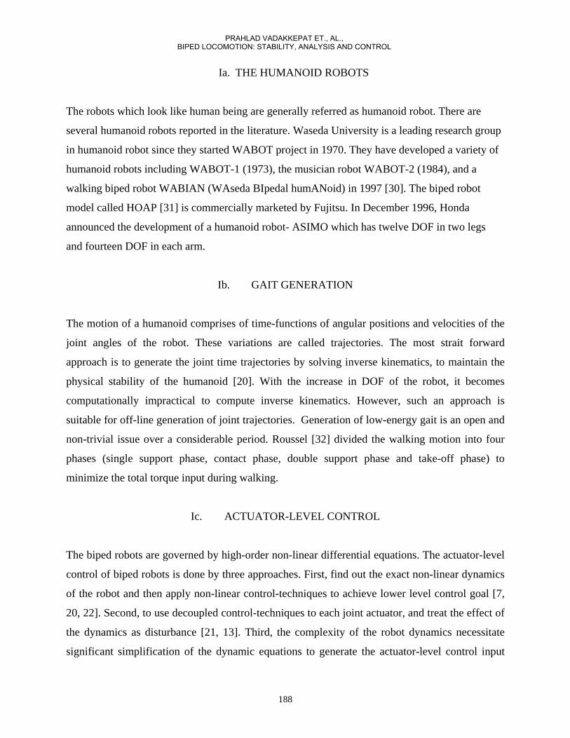
at all stages of the locomotion gait [1]. In figure 2, N is the net force and M is the net moment
acting at the point P. P is called the ZMP when net moment due to N and M disappears.
190
PRAHLAD VADAKKEPAT ET., AL., BIPED LOCOMOTION: STABILITY, ANALYSIS AND CONTROL
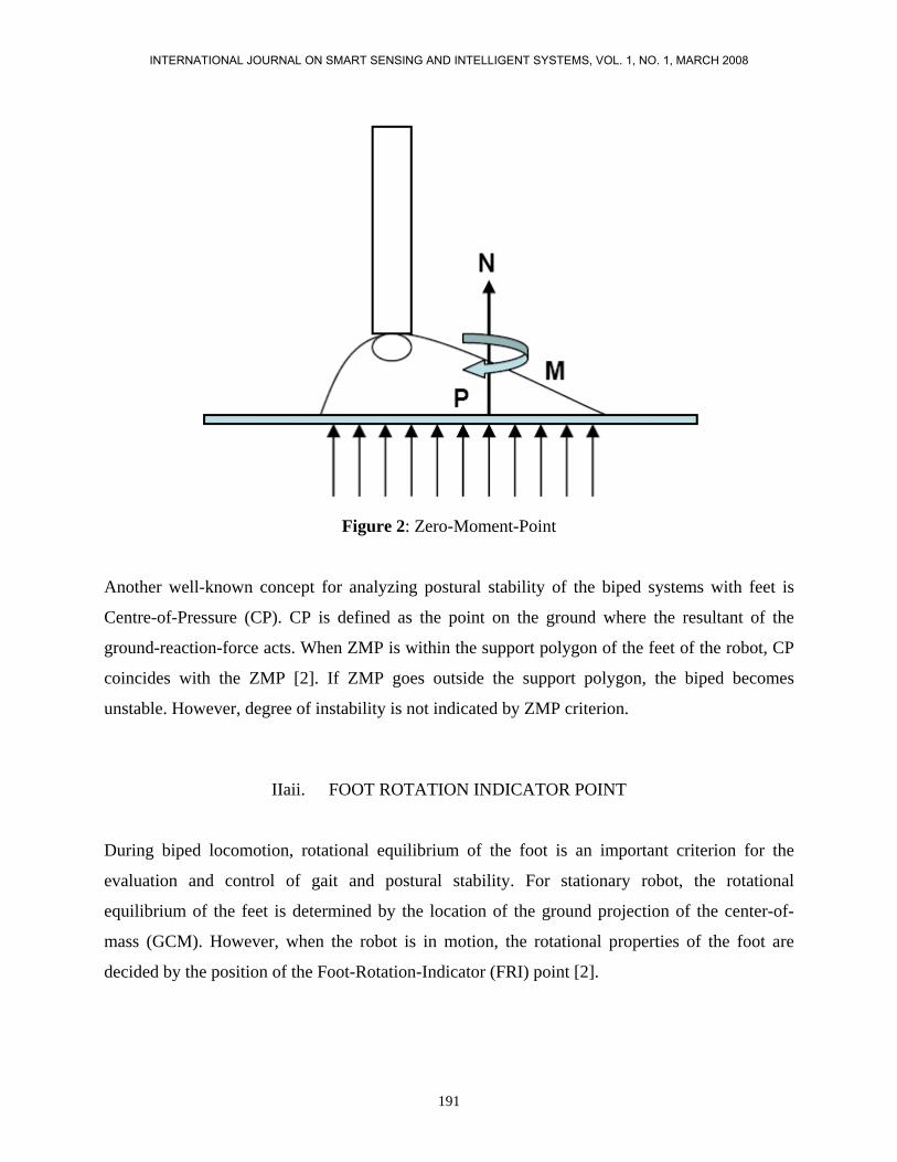
Figure 2: Zero-Moment-Point
Another well-known concept for analyzing postural stability of the biped systems with feet is
Centre-of-Pressure (CP). CP is defined as the point on the ground where the resultant of the
ground-reaction-force acts. When ZMP is within the support polygon of the feet of the robot, CP
coincides with the ZMP [2]. If ZMP goes outside the support polygon, the biped becomes
unstable. However, degree of instability is not indicated by ZMP criterion.
IIaii. FOOT ROTATION INDICATOR POINT
During biped locomotion, rotational equilibrium of the foot is an important criterion for the
evaluation and control of gait and postural stability. For stationary robot, the rotational
equilibrium of the feet is determined by the location of the ground projection of the center-of-
mass (GCM). However, when the robot is in motion, the rotational properties of the foot are
decided by the position of the Foot-Rotation-Indicator (FRI) point [2].
191
INTERNATIONAL JOURNAL ON SMART SENSING AND INTELLIGENT SYSTEMS, VOL. 1, NO. 1, MARCH 2008

Foot-Rotation-Indicator (FRI) is defined as the point on the foot-ground contact surface, within
or outside the support polygon, at which the resultant moment of the force/torque impressed on
the foot is normal to the surface. Alternatively, FRI point is the point on the foot-ground contact
surface where the net ground-reaction force would have to act to prevent foot rotation. The
location of the FRI point indicates the existence of unbalanced torque on the foot. The further
away the FRI point from the support polygon boundary, larger the unbalanced moment and
greater is the instability (figure 3).
It is worth noting that as long as the FRI point remains inside the support polygon,
CP=ZMP=FRI and the supporting foot does not rotate. The CP is a standard notion in mechanics
that was renamed as ZMP. The FRI point is a more general notion because it is defined when the
foot is rotation with respect to the walking surface [14].
Figure 3: FRI Point: F
192
PRAHLAD VADAKKEPAT ET., AL., BIPED LOCOMOTION: STABILITY, ANALYSIS AND CONTROL

IIaiii. BIPED MODEL WITH POINT FOOT-GROUND CONTACT
From recent literature [3, 4, 5] it can be noticed several researcher are investigating the stability
of biped systems without foot or point foot. Due to absence of foot (and support polygon),
stability concepts such as ZMP, FRI are not applicable to such systems and there is no statically
stable posture for these systems while they are in single-support phase. The motivation of these
biped models comes from the fact that an anthropomorphic walking gait should have a fully
actuated phase where the stance foot is flat on the ground, followed by an under-actuated phase
where the stance heel lifts from the ground and stance foot rotates abut toe. The point foot model
is simpler than a more complete anthropomorphic gait model.
The success of Raibert’s control law for a one-legged hopper [4] motivated others to analytically
characterize the stability of point foot biped systems. Due to absence of statically stable posture
in single-support phase, the locomotion studies of point foot biped systems are mainly performed
for periodic or repeated movements like walking, running, hopping or jogging (not standing or
jumping) (figure 4). Absence of active actuation at the joint between point-foot and the ground
makes these systems under-actuated. The stability of the under-actuated systems is essentially
governed by its zero-dynamic [6]. The zero-dynamics of these systems does not have any stable
equilibrium. However, the zero-dynamics can move from one bounded unstable solution to
another periodically leading to bounded zero-dynamics. The concept of orbital stability and
periodicity is applied to establish the periodicity of zero-dynamics by Raibert [3] and Koditchek
[5]. In [5], Poincare return map is used to show periodicity of motion of a simplified spring-
damped hopping robot. Similar concept is used by Grizzle et al. in [3] to establish the conditions
of periodicity for stable walking/running of a planar robot without foot.
Figure 4: Periodic Motion
193
INTERNATIONAL JOURNAL ON SMART SENSING AND INTELLIGENT SYSTEMS, VOL. 1, NO. 1, MARCH 2008

IIb. STABILIZATION AND CONTROL
It is seen in section IIa that the postural stability of the biped systems is analyzed by the
dynamics-based concepts such as ZMP, FRI or periodicity. The application of these concepts
requires knowledge of biped dynamics. Due to presence of several degrees-of-freedom (DOF),
the dynamics of biped systems are highly nonlinear and complex. Several formulation techniques
for the biped dynamics are available [7, 8]. Due to easy implementation in computer, most
commonly used methods are Newton-Euler dynamics formulation and Lagrangian dynamics
formulation. Using the system dynamics equations, postural stability of biped can be analyzed.
IIbi. POSTURAL STABILITY CONSIDERING ZMP
While using the concept of ZMP for postural stability analysis, the biped dynamics is very often
replaced by a simplified model which approximately reflects the dynamic behaviour of the
original system to minimize the difficulty in computing and analysing the full system dynamics.
The idea of replacing whole biped with a concentrated mass at the center-of-mass (CM), is
widely used for simplification of ZMP-based stability analysis. The simplified model is
commonly referred as inverted pendulum model (IPM).
In figure 5, entire biped model is replaced by the mass m placed at the location of CM (x, y, h). If
the vertical height of the CM is kept constant during locomotion, the dynamic behaviour of the
system is expressed as (1).
194
PRAHLAD VADAKKEPAT ET., AL., BIPED LOCOMOTION: STABILITY, ANALYSIS AND CONTROL

where g is the gravitational acceleration, , are the torque applied around x-axis and y-
axis respectively. Let be the position of the ZMP. It is clear from (1) that the
value of ZMP is,
Figure 5: Inverted Pendulum Model.
Using (2) in (1) the expression of ZMP become,
195
INTERNATIONAL JOURNAL ON SMART SENSING AND INTELLIGENT SYSTEMS, VOL. 1, NO. 1, MARCH 2008

From (1), (2) and (3), it is seen that the ZMP can be manipulated by changing the position of the
CM using the linear model. The model is well-known as Linear Inverted Pendulum Model
(LIPM) for its linearity [9, 10, 11]. In [9, 11], the LIPM is used for real-time ZMP following. The
CM is manipulated according to the reference ZMP position. In [10], the ZMP tracking problem
is formulated as servo problem. The ZMP reference is tracked using LIMP by a method called
preview control which uses future input to compute present output.
In [13], two-mass inverted pendulum model is used for designing linear optimal control to track
the ZMP trajectory. The technique uses ZMP as a feedback.
Another approach for simplification of biped dynamics is to identify the loosely coupled
components and decouple the original dynamics into number of linear and lesser complex
dynamics. In [12], the reference ZMP positions are achieved by decoupled and linearized version
of the full biped dynamics.
IIbii DECOUPLED AND LINEARIZED VERSION OF THE FULL BIPED DYNAMICS.
In recent times, the concept of FRI point for analyzing stability in biped locomotion is addressed
by researchers [14, 15, 16]. In [15], the FRI concept is used for generating periodic
anthropomorphic biped locomotion. The walking process is divided into two phases: Fully-
actuated phase during flat-foot stance leg and under-actuated phase while heel lift off the walking
surface. The conditions are established using FRI to ensure periodic occurrence of the two
phases. In [14, chapter 11], a method is described for directly controlling the position of the FRI
point using the ankle torque.
III. DISTURBANCE REJECTION USING ONLINE ZMP COMPENSATION
A trajectory-based ZMP compensation technique is proposed and implemented on humanoid
robot MaNUS-I [18, 19]. The humanoid robot MaNUS-1 was developed in Mechatronics and
Automation laboratory in National University of Singapore (figure 6). MaNUS-I has 12 degrees
of freedom in the lower body and each joint is driven by an Radio-Controlled servo motor [17]. A
196
PRAHLAD VADAKKEPAT ET., AL., BIPED LOCOMOTION: STABILITY, ANALYSIS AND CONTROL

Digital Signal Processor (DSP) (Motorola 56F807) controls walking motion of the robot by
sending the desired joint trajectory signals to various leg joint motors. The ZMP at each instant is
measured using force sensors located at the corners of each foot bottom. The DSP controller
receives and processes the data from force sensors. Compensation for the ankle reference angles
is calculated according to the deviation of the ZMP due to external disturbances.
IIIai. BIPED MODEL
During walking, when one leg is swinging, the mass of the whole body can be replaced by the
total mass of the robot located at the center of mass (CM) of the robot as point-mass and is
connected to the foot at stance like an inverted pendulum. The simplified model shown in figure
7 is used to approximate the biped model.
In figure 7, 'c' is the CM of the robot with one leg swinging and 'a' is the ankle-joint of the other
leg which is on the ground. (1,2) are the positions of the force sensors in x
and y directions, in sagittal and frontal plane respectively. is the distance of the CM from
ankle-joint in sagittal plane. L is the distance of ZMP from the ankle joint. can be considered
as a link with concentrated point-mass at the end. is the angle between the link and the z-axis.
is the angle between L and the z-axis. is the torque at the ankle-joint about y-axis.
is the disturbance force applied to the robot as disturbance. are the reading of force sensors
in the respective plane. 'm' is the total mass of the robot and 'g' is the gravitational acceleration.
The motions in the sagittal plane and frontal plane are considered separately because the motions
in these two planes are weakly coupled [18].
IIIaii. MEASUREMENT OF ZMP USING FORCE SENSORS
Tekscan FlexiForce force sensors are used to measure the forces acting on the feet of the robot.
197
INTERNATIONAL JOURNAL ON SMART SENSING AND INTELLIGENT SYSTEMS, VOL. 1, NO. 1, MARCH 2008

Figure 6: MaNUS-I.
For the measurement of ZMP, four force sensors are placed at the bottom of each foot. The
positions of the foor sensors at the bottom of the feet of the robot, are illustrated in figure 8. The
Safety Zone (indicated in the figure 8) is the portion of the support polygon where the ZMP of the
robot should be located for better stability.
In this compensation technique, using the reading of the force sensors the position of the CP is
measured. ZMP coincides with CP while ZMP is within the support polygon [2].
The ZMP in sagittal plane (x-direction) is computed by (4) using force sensor reading.
198
PRAHLAD VADAKKEPAT ET., AL., BIPED LOCOMOTION: STABILITY, ANALYSIS AND CONTROL

Similarly, ZMP is calculated in frontal plane using force sensor reading.
Figure7: Simplified Biped Model.
199
INTERNATIONAL JOURNAL ON SMART SENSING AND INTELLIGENT SYSTEMS, VOL. 1, NO. 1, MARCH 2008

Figure 8: Positions of the force sensors.
IIIaiii. ONLINE ZMP COMPENSATION
Suppose at the (k-1)th sampling interval, the x-ZMP position is which is within the 'Safety
Zone'. The moment about during (k-1)th sampling interval is given by (5).
When an disturbance force is acting on the robot in x-direction and compensation is not
applied, at kth sampling interval the moment about is computed, using (4) and (5), by (6).
The amount of torque compensation required at ankle joint to overcome the effect of the
disturbances is given by (details of the proof is available in [18]),
200
PRAHLAD VADAKKEPAT ET., AL., BIPED LOCOMOTION: STABILITY, ANALYSIS AND CONTROL

The overall block diagram of the compensation technique is shown in the figure 9.
Figure 9: Online ZMP Compensation
IIIaiv APPLICATIONS AND EXPERIMENTS
The effectiveness of the compensation method is verified on a humanoid robot, MaNUS-I. With
the compensation technique, the robot successfully rejected disturbances in different forms.
A. IMPROVEMENT OF WALKING ON FLAT SURFACE
x-ZMP positions of the robot are computed from the force measurements while walking on a flat
surface using (4). The compensation technique comes into play whenever the x-ZMP position
goes beyond the 'Safety Zone'. The compensation angle at the ankle-joint is calculated using (6)
and (7). The robot is made to walk on a flat surface without compensation and with compensation
over a period of 20 seconds. Figures 10 and 11 show the recorded x-ZMP positions once the
walking gait is stabilized starting from a standing position. It is clear from the results that the
compensator is able to reduce the magnitude of fluctuation of the ZMP keeping its value within
the 'Safety Zone'.
201
INTERNATIONAL JOURNAL ON SMART SENSING AND INTELLIGENT SYSTEMS, VOL. 1, NO. 1, MARCH 2008
B. REJECTING DISTURBANCE DUE TO SUDDEN PUSH
With the compensation at place, the robot's walking gait is more robust to sudden disturbances
such as a slight push from behind or from the front. When the robot experiences a push, the ZMP
shifts momentarily out of the expected position and goes beyond the 'Safety Zone'. By ankle-
joint-compensation the robot is able to revert back its ZMP position after certain walking cycles
depending on the size of the disturbance.
The amount of maximum disturbance which can be rejected is dependent on the torque-rating of
the ankle-pitch-joint actuator. MaNUS-I uses Radio-Controlled servo motor with torque rating
0.13 Nm at the ankle-joints. The maximum forward force (from behind) that the robot can reject
is around 3 Newton while it is able to reject a maximum backward force of around 1.2 Newton.
C. WALKING UP AND DOWN A SLOPE
While walking up/down the slope, the compensation angle varies with inclination of the slope.
With increase in slope the compensation increases. As the compensation angle is changing
slowly, the robot adapts to a change in inclination successfully only after about 1 to 2 seconds
depending on the angle of inclination. Due to limitation in ankle-pitch-joint actuator torque-
rating, robot is able to walk up a maximum slope of 100 and walk down a maximum slope of 30
on a wooden plank. Figures 12 and 13 show the humanoid robot, MaNUS-I, walking up and
down the slope respectively.
202
PRAHLAD VADAKKEPAT ET., AL., BIPED LOCOMOTION: STABILITY, ANALYSIS AND CONTROL

Figure 10: x-ZMP position during walking without compensation
D. CARRYING WEIGHT DURING WALKING
For walking with additional weight, a basket is attached on the back of MaNUS-I (figure 14).
After the compensation technique is applied, the robot is able to carry a maximum of 26 batteries
including a metal basket with a total weight of 390 gm and continue walking on a flat surface.
The mass of the robot being 2.36 kg, the additional weight is approximately 17\% of the robot's
weight.
As the constant additional weight causes the ZMP to shift, the compensation method adjusts the
ankle-pitch-angle gradually until the ZMP moves within the 'Safety Zone'.
VI. CONCLUSIONS
Postural stability in bipedal systems has been a research challenge for more than three decades.
Until late nineties the concept of ZMP was the only technique to analyse the stability of the
legged systems. After the idea of FRI point is introduced, the bipedal stability analysis is able to
address a wider class of bipedal motion where the foot of the robot rotates during walking. Due to
the rotation of foot, one more DOF is added to the system making the system under-actuated. To
203
INTERNATIONAL JOURNAL ON SMART SENSING AND INTELLIGENT SYSTEMS, VOL. 1, NO. 1, MARCH 2008
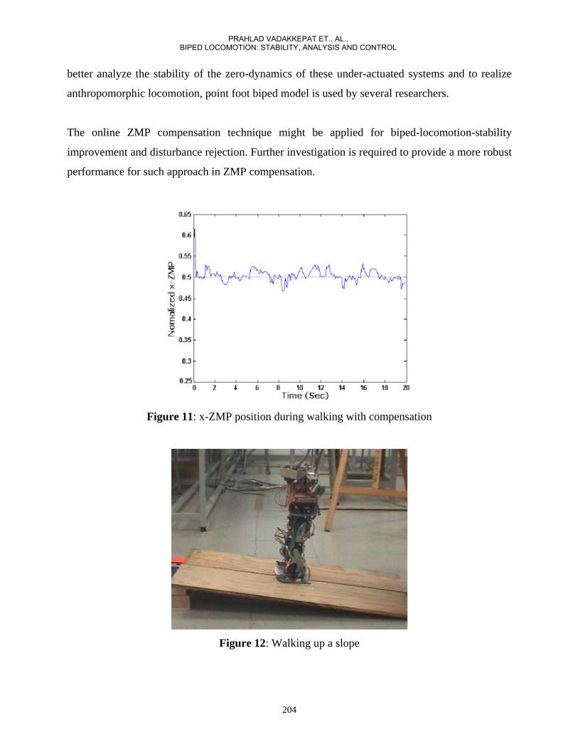
better analyze the stability of the zero-dynamics of these under-actuated systems and to realize
anthropomorphic locomotion, point foot biped model is used by several researchers.
The online ZMP compensation technique might be applied for biped-locomotion-stability
improvement and disturbance rejection. Further investigation is required to provide a more robust
performance for such approach in ZMP compensation.
Figure 11: x-ZMP position during walking with compensation
Figure 12: Walking up a slope
204
PRAHLAD VADAKKEPAT ET., AL., BIPED LOCOMOTION: STABILITY, ANALYSIS AND CONTROL

REFERENCES
[1] M. Vukobratovic and B. Borovac, “Zero Moment Point - Thirty Five Years of its Life”, International Journal of Humanoid Robotics Vol. 1, No.1 157-173, (2002). [2] A. Goswami, “Postural Stability of Biped Robots and the Foot-Rotation-Indicator (FRI) Point”, The International Journal of Robotics Research, Vol. 18, No 6, pp. 523-533, (1999)
Figure 13: Walking down a slope
Figure 14: MaNUS-I carrying additional Weight
[3] C. Chevallereau, E.R. Westervelt and J. W. Grizzle, "Asymptotically Stable Running for a Five-Link, Four-Actuator, Planar Bipedal Robot," The International Journal of Robotics Research, Vol. 24, No 6, pp. 431-464, (2005).
205
INTERNATIONAL JOURNAL ON SMART SENSING AND INTELLIGENT SYSTEMS, VOL. 1, NO. 1, MARCH 2008

[4] M. Raibert, “Legged Robots That Balance”, MIT press, Cambridge, MA. [5] E. Koditschek and Martin Bühler, "Analysis of a Simplified Hopping Robot", The International Journal of Robotics Research, Vol. 10, No. 6, pp. 587-605 (1991). [6] A. Isidori, “Nonlinear Control Systems: An Introduction”, Springer-Verlag, Berlin (1995). [7] JJ Craig, “Introduction to Robotics: Mechanics and Control”, Addison-Wesley Longman Publishing Co., Inc. Boston, MA, USA (1989). [8] KS Fu, RC Gonzalez, CSG Lee, “Robotics: control, sensing, vision, and intelligence”, McGraw-Hill, Inc. New York, NY, USA (1987). [9] T. Sugihara, Y. Nakamura, H. Inoue, “Real-time humanoid motion generation through ZMP manipulation based on inverted pendulum control”, IEEE International Conference on Robotics and Automation, Vol. 2, pp. 1404-1409 (2002). [10] S. Kajita, F. Kanehiro, K. Kaneko, K. Fujiwara, K. Harada, K. Yokoi, H. Hirukawa, “Biped walking pattern generation by using preview control of zero-moment point”, IEEE International Conference on Robotics and Automation, Vol. 2, pp. 1620-1626 (2003). [11] S. Kajita, O. Matsumoto, M. Saigo, “Real-time 3D walking pattern generation for a biped robot with telescopic legs”, IEEE International Conference on Robotics and Automation, Vol. 2, pp. 2299-2306 (2001). [12] Hun-ok Lim, Y. Yamamoto, A. Takanishi,, “Control to realize human-like walking of a biped humanoid robot”, IEEE International Conference on Systems, Man, and Cybernetics, Vol. 5, pp. 3271-3276 (2000). [13] Napoleon, S.Nakaura, M. Sampei, “Balance control analysis of humanoid robot based on ZMP feedback control”, IEEE International Conference on Intelligent Robots and System, Vol. 3, pp. 2437-2442 (2002). [14] ER Westervelt, JW Grizzle, C. Chevallerau, JH Choi, B. Morris “Feedback control of dynamic bipedal robot locomotion”, Boca Raton : CRC Press (2007). [15] JH Choi, JW Grizzle, “Planar bipedal walking with foot rotation”, American Control Conference, Vol. 7, pp. 4909- 4916 (2005). [16] A.Goswami, “Foot rotation indicator (FRI) point: a new gait planning tool toevaluate postural stability of biped robots”, IEEE International Conference on Robotics and Automation, Vol. 1, pp. 47-52 (1999). [17] http://www.hitecrcd.com/homepage/product-fs.htm. [18] P. Vadakkepat, D. Goswami, Chia Meng Hwee, “Disturbance Rejection by Online ZMP Compensation”, Robotica. [19] P. Vadakkepat, D. Goswami, "MaNUS Humanoid: A Test bed for Advanced Robotics Research". Int. Conf. on Emerging Mechanical Technology - Macro to Nano, ed. R. K. Mittal and N. N. Sharma (2007): 195-203. (Keynote paper) . [20] WA Gruver, TT Lee, PL Jeng, “Control of a 5-link biped robot for steady walking”, IEEE International Symposium on Intelligent Control, pp 484-489 (1998).
206
PRAHLAD VADAKKEPAT ET., AL., BIPED LOCOMOTION: STABILITY, ANALYSIS AND CONTROL

[21] K. Mitobe, N. Mori N, K. Aida, Y. Nasu, “Nonlinear feedback control of a biped walking robot”, Proceedings of 1995 IEEE International Conference on Robotics and Automation, Vol. 3, pp 2865 – 2870 (1995). [22] Vibet M, “Control law decoupling for 2-D biped walking system Cotsaftis”, IEEE Engineering in Medicine and Biology Magazine, Volume 7, Issue: 3, pp 41-45 (1988). [23] Hsia TCS, Lasky TA, Guo Z. “Robust independent joint controller design for industrial robot manipulators”, IEEE Transactions on Industrial Electronics, Volume 38, Issue 1, pp 21-25 (1991). [24] JS Albus, “A new approach to manipulator control: the cerebellar model articulation controller (CMAC)”, ASME Journal of Dynamic systems, Measurements and Control, pp 220-227, (1975). [25] YH Kim, FL Lewis, “Optimal design of CMAC neural-network controller for robot manipulators”, IEEE Transactions on Systems, Man and Cybernetics: Part C, Vol. 30, Issue 1, pp 22-31 (2000). [26] DM Katic, MK Vukobratovic, “Highly efficient robot dynamics learning by decomposed connectionist feedforward control structure”, IEEE Transactions on Systems, Man and Cybernetics, Vol. 25, Issue 1, pp 145 – 158 (1995). [27] P. Martinet, J. Gallice, “Position based visual servoing using a non-linear approach”, IROS, Vol. 1, pp 531-536 (1999). [28] M. Asada, T. Tanaka, K. Hosoda. “Visual tracking of unknown moving object by adaptive binocular visual servoing”, IEEE/SICE/RSJ International Conference on Multisensor Fusion and Integration for Intelligent Systems, pp 249-254 (1999). [29] Do Hyoung Kim, Do-Yoon Kim, Hyun Seok Hong, Myung Jin Chung, “An image-based control scheme for an active stereo vision system”, IROS, Vol. 4, 28, pp 3375-3380 (2004). [30] J. Yamaguchi, D. Nishino, A. Takanishi, “Realization of dynamic biped walking varying joint stiffness using antagonistic driven joints”, Proceedings of International Conference of Robotics and Automation, Vol. 3, pp 2022-2029 (1998). [31] M. Ogino, Y. Katoh, M. Aono, M. Asada, K. Hosoda, “Vision-based reinforcement learning for humanoid behaviour generation with rhythmic walking parameters”, Proceedings of IROS, Vol. 2, pp 1665-1671 (2003). [32] L. Roussel, C.-De-Wit, A. Goswami, “Generation of energy optimal complete gait cycles for biped robots”, IEEE International Conference on Robotics and Automation, Vol. 3, Page(s): 2036-2041 (1998).
207
INTERNATIONAL JOURNAL ON SMART SENSING AND INTELLIGENT SYSTEMS, VOL. 1, NO. 1, MARCH 2008


![Using a Biological Material to Improve Locomotion of ... · Locomotion of Hexapod Robots ... support, stability, and movement to ... [2,3] in order to approach animals in their levels](https://img.dokumen.tips/doc/110x75/5b16f60e7f8b9a6f218b8ad4/using-a-biological-material-to-improve-locomotion-of-locomotion-of-hexapod.jpg)