Embed Size (px)
Citation preview

International Journal of Scientific and Research Publications, Volume 3, Issue 6, June 2013 1 ISSN 2250-3153
www.ijsrp.org
Biological Sulphate Reduction with Hydrogen in a Jet
Loop Biofilm Reactor
Renu Pawels*, Ajit Haridas**, Babu.T.Jose**
* School of Engineering, Cochin University of Science & Technology (CUSAT) ** Process Engineering and Environmental Technology Division, NIIST (CSIR)
** School of Engineering, Cochin University of Science & Technology (CUSAT)
Abstract- Biological sulphate reduction is a new technology that can be used for the treatment of wastewater containing high
amounts of sulpates and metals. The objective of this work was to investigate the feasibility and efficiency of biological sulphate
reduction in a sulphidogenic jet loop biofilm reactor using hydrogen as electron donor. Polystyrene balls (qty: 265g, size > 2mm,
density: 135 kg/m3, total surface area : 2.29 m
2) were used, for the first time in this research as floating carrier material for bacterial
attachment. In this jet loop reactor, high mass transfer rate between hydrogen and sulphate reducing active biomass is achieved by
using a liquid jet drive. The reactor was run in mesophilc condition (340C) and a pH controller unit was fitted to maintain the reactor
pH at optimum for bacterial growth and reducing the H2S toxicity. The maximum sulphate reduction obtained was 7.3 g SO42-
l/d for
a sulphate loading of 7.48g SO42-
l/d.
Index Terms- Activity, Biofilm, Sulphate reduction, Sulphate reducing bacteria, Sulphidogenic jet loop biofilm reactor
I. INTRODUCTION
Wastewaters from mining and mineral processing are often characterized by low pH, high metal and sulphate concentrations.
Traditionally, diluted acid sulphate streams are treated with calcium hydroxide, which yields gypsum. This toxic sludge produced with
chemical treatment needs further downstream processing and detoxification [1].
In recent years, an increased interest has been expressed in the anaerobic treatment of sulphate-rich wastewaters. The primary
difficulty in applying anaerobic treat technologies to sulphate containing wastewaters arises from the production of free undissociated
hydrogen sulphide (H2S) by SRB and from it toxicity towards the various tropic groups of bacteria involved in the process [2,3].
Inhibition decreases the efficiency of reactor performance and can even lead to complete process failure [4]
Biological sulphate reduction (BSR) has a number of advantages over other processes. Sulphate reducing bacteria (SRB) utilize
sulphate as an electron acceptor in the oxidation of an energy substrate with the production of sulphide, which may react with heavy
metals to precipitate them out as metal sulphides.. The metal separation and settling rates obtained with hydroxide precipitates are
lower than those obtained with sulphide precipitates, and most metal sulphides have lower solubilities even at acidic pH. Furthermore,
biologically precipitated metal sulphides can be recovered and recycled.
Acidic metal sulphate wastewaters usually contain relatively low concentrations of organic substrates. Therefore, addition of a suitable
carbon source and electron donor is often necessary [5] for cell growth. In most cases, these two roles are filled by one compound (for
example ethanol or a short chain fatty acid). It is advantageous to use hydrogen as electron donor (energy source) in place of organic
sources in order to reduce cost as well as to ensure low residual COD in liquid [6]
Anaerobic treatment of sulphur rich wastewaters has been reviewed by Rinzema and Lettinga [7]. Maree and Stardom [8] studied
sulphate reduction in a packed bed reactor and observed a reduction rate of 6.5 g SO42-
l/d. Nagpal et al [9] attained sulphate reduction
rates up to 6.33 g SO42-
l/d in an ethanol fed system consisting of a FBR and a separate recirculation vessel (recirculating fluidized-bed
reactor (RFBR)) at a HRT of 5.1 hr. It has been shown previously that mesophilic sulphate reducing bacteria are able to aggregate in
gas-lift reactors fed with H2/CO2 or H2/CO gas mixtures [10]. A maximum sulphate conversion rate of 30 g SO42-
l/d could be
achieved after only 10 days of operation. The hydrogen mass transfer capacity of the reactor determined the maximum sulphate
conversion rate.
Jet loop reactor with self-aspiration of gas has the advantage of high mass transfer and would be suitable for H2-driven sulphate
reduction. The earlier investigations, reported on jet-propelled loop reactors, are concerned with a central tube and a two fluid nozzle
at the bottom of the reactor. This type of arrangement is disadvantageous when the reactor is used as a wastewater treatment reactor
or in processes involving sparingly soluble gas, due to the blockage of the nozzle and a lower residence time of the gaseous phase.
Thus, as an alternative, a sulphidogenic jet loop biofilm reactor (SJLBR) was developed at Regional Research Laboratory (RRL),
Thiruvananthapuram, for the treatment of metal sulphate wastewater using hydrogen as electron donor [11,12,13]. The gas phase
residence time can be increased considerably in the down-flow reactor when the H2 gas is introduced from the top of the reactor into a
International Journal of Scientific and Research Publications, Volume 3, Issue 6, June 2013 2
ISSN 2250-3153
www.ijsrp.org
fluid that is flowing co-currently downwards so the bubbles are forced to move in a direction opposite to their buoyancy. The use of
buoyant biofilm media enable simple removal of produced sulphides without fouling of biofilms while maintaining efficient gas –
liquid – biofilm contacting (US Patent : 6527948, 6544421). This paper describes the performance of sulphidogenic jet loop biofilm
reactor for the treatment of synthetic sulphate rich wastewater
II. IDENTIFY, RESEARCH AND COLLECT IDEA
2. MATERIALS AND METHODS
The experimental set-up (figure 1) comprises a glass reactor vessel (liquid height 1.25m, inner diameter 0.1 m), a strainer glass vessel
(height 0.65 m, inner diameter 0.1m), a recirculation pump and a two-fluid jet fitted at the top of the reactor. In this loop reactor, the
circulation and gas dispersion is achieved by the jet drive. The headspace of the reactor is connected to a floating gasholder. It consists
of a tank filled with water in the bottom and hydrogen gas at the top. The gas can be filled by a tube line, which is connected to
hydrogen gas cylinder (Specification: IS 7285:1988, O.D 232mm, Overall length: 1370mm, Minimum wall thickness: 5.5 mm, Water
capacity: 46.7 litre, Working pressure: 150 kgf/cm2). Hydrogen utilization can be measured directly with a scale provided on the
floating gasholder. Since hydrogen is poorly soluble, the unreacted gas exiting the reactor is recycled through the jet drive. High
velocity liquid and hydrogen gas injected into a bioreactor via the two-fluid jet nozzle are directed into an internal draft tube (length
0.64 m, inner diameter 0.032 m) causing a loop circulation of the fluid-dispersion in the reactor. The draft tube minimizes the bubble
coalescence and thus maintains small bubbles. The biologically active reactor volume was 9.8 L. Polystyrene balls (qty: 265g, size >2
mm, density 135 kg /m3, total surface area: 2.29 m
2) were used as floating biofilm carrier material.
Below the draft tube, a deflection cup is provided to get the maximum agitation and to provide a low agitation separation zone in the
bottom of the reactor where metal precipitate may settle and buoyant beads can rise back into the reactor zone. While the biomass
retains on a floating carrier material, the effluent can be withdrawn at the bottom of the reactor and partly recirculated to the jet by
means of a recirculation pump (flow rate; 1440 litre/hr). A strainer (length 250mm, diameter 63 mm, flow area: 90.32 cm2) is provided
before the nozzle, to prevent it’s chocking, because of the small scale of the system. A pressure gauge (0-7 kgf/cm2) is provided in the
circulation pipeline to monitor pressure at the 2-fluid jet. A constant pressure of (1.2 kgf/cm2) was maintained during the operation.
The feed solutions were prepared in feed tanks A & B. The feed A & B were pumped to a safety vent tube with peristaltic pumps A &
B respectively, from which it flows by gravity into the reactor. The mechanism also prevents the loss of liquid from the reactor in
case of any feed pump failure. The overflow line is used to take out the treated effluent from the reactor.

International Journal of Scientific and Research Publications, Volume 3, Issue 6, June 2013 3
ISSN 2250-3153
www.ijsrp.org
International Journal of Scientific and Research Publications, Volume 3, Issue 6, June 2013 4
ISSN 2250-3153
www.ijsrp.org
2.1 Biofilm carrier materials
100 ml anaerobic sludge obtained from wastewater treatment plant of distilleries was fed to the reactor initially as seed culture. A new
material (Expandable polystyrene beads) for bacterial attachment in sulphidogenic reactors was developed. The reactor was loaded
with polystyrene beads (expanded at 900c for 20-25 min), which were of size greater than 2 mm. The properties of the beads as density
135 kg/m3 , rise velocity: 16.5 cm/sec, surface area: 0.125 cm
2 per bead. Polystyrene beads were used for first time as carrier materials
for bacterial attachment based on its availability, larger surface area and lower density
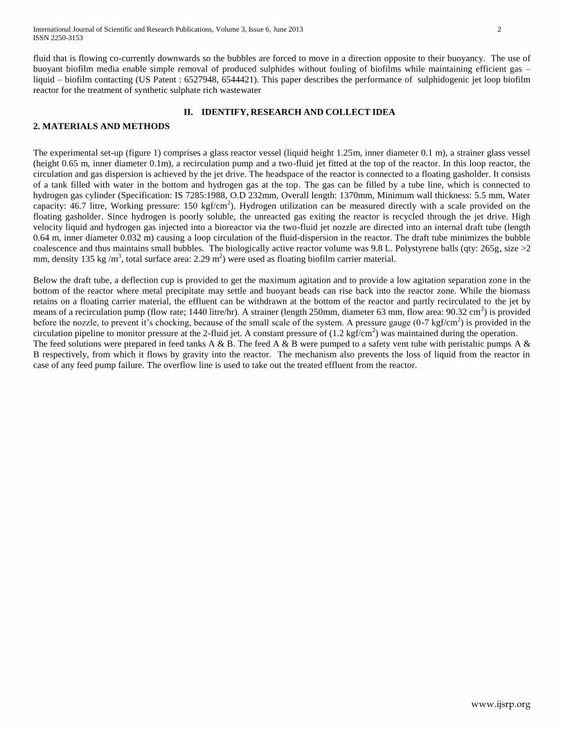
Biofilm activity tests were conducted in a fermenter vessel equipped with a central axis turbine stirrer and a draft tube for gas
aspiration and dispersion (figure 2 & 3). A mariotte flask filled with H2 is connected to the reactor. As H2 is consumed by the
reaction, it is replenished from the mariotte flask. The displaced volume is made up by water dropping from a constant head reservoir
and thereby maintains constant pressure in the system.
2.2 Composition of synthetic wastewater
The reactor was tested for the treatment of a synthetic wastewater-containing sulphate. In the first experiment, synthetic wastewater
containing sulphate 4 g SO42-
/d (as sodium sulphate), essential growth medium comprising macronutrients 5.8 ml/l, trace elements 5.8
ml/l, vitamins 1.6 ml/l (Composition of which is given in Tables 1, 2 & 3), NaHCO3 (0.8 g/d), glucose(0.8 g/d), yeast extract (1.2 g/d)
and sodium sulphite (1.52 g SO42-
/d) were taken in feed tank A and pumped to the reactor at a flow rate of 15 l/d. Sodium sulphite was
added to remove the dissolved oxygen in feed water.

International Journal of Scientific and Research Publications, Volume 3, Issue 6, June 2013 5
ISSN 2250-3153
www.ijsrp.org
Second experiment was conducted from the 7th
day, to check the H2S toxicity in the reactor by recycling the effluent from the reactor.
Sodium sulphite feed (sulphate load: 11.8 g/d) was added through feed B at a flow rate of 70 l/d. Feed A was reduced to 1 l/d
(Sulphate load: 6.2 g/d). On 9th
day, sulphate loadings of feed A & B were increased to 15 g SO42-
/d and 24 g SO42-
/d respectively and
flow rate of feed B was changed to 150 l/d.
In the third experiment, pH of the reactor liquid was controlled with a pH-electrode connected to a pH controller. Sodium sulphate (15
g SO42-
/l.d) and sulphuric acid (15 g SO42-
/l.d) were loaded from the feed tank A to the reactor via peristaltic pump A at a flow rate of
1.5 l/d. The essential growth medium as mentioned above was also added to it. In order avoid any toxicity due to sulphite added for
removal of dissolved oxygen toxicity is affecting the reactor, sulphide (75% Tap water + 25 % sulphide effluent from the reactor) was
used in this experiment for removing oxygen from dilution feed B, maintained at 90 l/d.
In the fourth experiment, sulphuric acid (6.78 g SO42-
/l.d) alone was loaded from the feed tank A to the reactor via peristaltic pump A
at a flow rate of 1.5 l/d. The essential growth medium was also added to it. Sulphide was used as oxygen scavenger in the dilution
feed B, maintained at 110 l/d.
2.3 Analytical methods
Sulphate concentration was determined using the gravimetric method (19th
Edition 1995, Standard methods for the examination of
water and wastewater, APHA, AWWA WEF). Dissolved sulphide analysis was done by iodometric method (19th
Edition 1995,
APHA, AWWA WEF). The entire effluent sample was filtered with 0.45 m membrane filter before analysis. All pH determinations
were made on unfiltered samples immediately after collection using a Systronics pH meter. pH, ORP and temperature were monitored
daily.
Table 1 Composition of the macronutrients for
sulphate reduction
Components Concentration
g/L
NH4Cl 180
KCl 12
KH2PO4 46
MgCl26H2O 30
CaCl22H2O 11
Table 2 Composition of trace elements
Components Concentration
(mg/l)
FeCl2 4H2O 2000
MnCl2 500
Resazurin 500
EDTA 500
Na2SeO3 100
H3BO3 50
ZnCl2 50
(NH4)6Mo7O244H2O 50
AlCl3 50
NiCl26H2O 50
COCl22H2O 50
HCL 36% (1ml/L)
Table 3 Vitamin for SRB
Component Concentration
g/L
4- Amino benzoic acid 0.01
Biotin 0.003
Cyanocobalamin 0.0002
Folic acid 0.003
Nicotinic acid 0.01
Riboflavin 0.01

International Journal of Scientific and Research Publications, Volume 3, Issue 6, June 2013 6
ISSN 2250-3153
www.ijsrp.org
For the estimation of biomass, a known quantity of bacteria immobilized beads were transferred to a kjeldhal flask and digested as per
Standard Method (4500 –Norg B. Macro- Kjeldahl method, 19th
Edition 1999, APHA, AWWA, WEF). Ammonia nitrogen was
determined with an Orion Ammonia Electrode and biomass was calculated (assuming 113 g of biomass contain 14 g of nitrogen).
III. WRITE DOWN YOUR STUDIES AND FINDINGS
3 RESULTS AND DISCUSSIONS
3.1 First experiment
In the first experiment, reactor was run in continuous mode for 10 days at a mesophilic temperature of 34OC. The reactor was
started with a sulphate concentration of 339 mg/l. The sulphate load and sulphate reduction corresponding to next 10 days of operation
are shown in figure 4. From 6th
day, feed B was increased to 70 l/d (hence sulphate concentration was 234 mg/l) and a sulphate
reduction of 0.93g SO42-
/l.d was obtained. The sulphide concentration was determined as 72 mg/l. From 9th
day, feed B was increased
to 150 l/d (sulphate load increased to 4 g SO42-
/l.d). The sulphide concentration reduced to 19 mg/l because of dilution. After 10 days
of operation at this condition, sulphate reduction rate obtained was 1.76 g SO42-
/l.d for a loading of 4 g SO42-
/l.d. Sulphate reduction
rate and hydrogen consumption rate obtained was plotted in figure 5. The maximum sulphate reduction was 17.2 g/d for a hydrogen
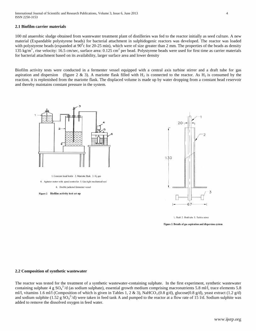
consumption rate of 1.46 g/d (18.2 L). pH was in range 8 – 8.5 from 4th
day onwards (figure 6).
Bacteria immobilized beads (2 g) were taken out from the reactor and activity tests were carried out to find out the activity of
SRB attached on the beads. The activity obtained for 2 mm beads was 0.12 g SO42-
reduction per g of beads per day. Therefore the
reactor should have shown 32 g SO42 reduction/d, which is much higher than actual obtained. Therefore, further studies were
conducted to find out the rate limiting parameter of the reactor.
3.2 Second Experiment
The second study was conducted to find out whether the reaction rate was limited by H2S toxicity. The reactor was operated
in full recirculation mode (effluent from the overflow line pumped backed into the reactor). Rate of hydrogen consumption was noted
down every hour. Time variation of hydrogen consumption is shown in figure 7. From the graph, it was clear that hydrogen
consumption rate was nearly constant for three days even though sulphide concentration increased during consecutive days.
Therefore, sulphide toxicity was not the rate limiting parameter in range of 28 to 86 mg/l as sulphur (S).

International Journal of Scientific and Research Publications, Volume 3, Issue 6, June 2013 7
ISSN 2250-3153
www.ijsrp.org
International Journal of Scientific and Research Publications, Volume 3, Issue 6, June 2013 8
ISSN 2250-3153
www.ijsrp.org
3.3 Third Experiment
The third study was conducted after cleaning the filter in strainer vessel. The reactor was started in continuous mode and
the pH in the reactor solution was maintained as 7.0 by pH controller. Sulphate load and reduction rate are shown in figure 8. After
four days of operation, sulphate reduction rate obtained was 3.27 g SO42-
/l.d (32 g SO42-
/d) for a sulphate load of 5.4 g SO42-
/l.d (53
g/d). The sulphide concentration was 88 mg/l, which is matching with the sulphate reduction. Hydrogen consumption and sulphate
reduction rate were plotted as in figure 9. From day 4-7, feed B flow rate was increased. Hydrogen consumption rate was reduced
during these days. This was suspected to be due to O2 input through the feed water. Therefore, feed B flow rate was decreased from
160 l/d to 90 l/d to reduce oxygen input. Sulphate reduction rate increased to about 3.72 g SO42-
/l.d (36.7 g SO42-
/d) with hydrogen
consumption of 38.5 l.
The maximum sulphate reduction obtained on 20th
day was about 43.8 g/d for a hydrogen consumption of 45.9 l. The
sulphide concentration was found to be 224 mg/l and pH was increased to 8.5. It was also noticed that a few beads changed from black
to white. This indicates detachment of biomass from the beads surface after attaining the maximum growth. From activity test, the
activity of beads taken from the reactor was determined to be 0.1664 g SO42-
reduced per g of beads per day. Therefore, the expected
reaction rate in sulphidogenic biofilm reactor was 44 g SO42-
reduced per day which matches the value obtained in the reactor. In this
condition, biomass was limiting the reaction rate in sulphidogenic jet loop biofilm reactor. After 22 days of operation, the maximum
sulphate reduction obtained was about 5 g SO42-
/l.d for a sulphate load of 5.5 g SO42-
/l.d.
From 23rd
day onwards, H2SO4 alone was given as the sulphate source (6.78 g SO42-
/l.d). Feed B was increased to 160 l/d.
Hydrogen consumption rate was started to decrease. Either or both, H2S toxicity and oxygen toxicity due to higher feed flow rate may
have caused the observed decrease. Then the reactor pH was adjusted from 7 to 7.5 for reducing the toxicity of free H2S. But no better
consumption rate was noticed. In order to check the oxygen toxicity, the reactor was operated in full recycle mode (recycled the
effluent from the reactor). Hydrogen consumption rate increased. Therefore, it was inferred that sulphate reduction rate decreased at
higher hydraulic loading rate again due to oxygen toxicity.

International Journal of Scientific and Research Publications, Volume 3, Issue 6, June 2013 9
ISSN 2250-3153
www.ijsrp.org
3.4 Fourth Experiment
The filter in strainer vessel was cleaned and the reactor was restarted with feed B in continuous mode at a flow rate of 110
l/d. Daily sulphate load and sulphate reduction during next few days are shown in figure 10. Mass transfer rate was improved (higher
recycling rate) by removing the beads choking the filter. In this condition, a maximum sulphate reduction of 7.3 g SO42-
/l.d (97.5 %)
was achieved at a sulphate-loading rate of 7.48 g SO42-
/l.d. After obtaining steady conditions, activity of beads was determined by
activity test as 0.327 g SO42-
reduction per g of beads per day. Therefore, the expected reduction of sulphate in the reactor was 71.6 g
SO42-
/d, which matches with the actual value obtained. Therefore, biomass was the rate limiting parameter in the reactor at this stage.
Results of activity tests with bacteria immobilized 2 mm beads at various time during the history of the sulphidogenic jet loop
biofilm reactor showed that SRB activity was improved with time (Table 4). Therefore, sulphate-reducing bacteria are able to form
biofilms under turbulent conditions also. The bacterial attachment on polystyrene beads was determined as 30 mg biomass per g of
beads. Therefore, biomass activity is 2.72 g S per gram of biomass per day after 7 months of the operation of the reactor. This is
significantly higher than that reported by Houten et al.(1995), i.e 0.7-1.4 g S per gram of biomass per day. It indicates that the biofilm
on the surface of the polystyrene balls under the prevailing turbulent conditions is extremely active. The biofilm formed on the surface
of the polystyrene balls is possibly thinner and has relatively less inner layers with lower activity. This hypothesis also explains the
sensitivity towards oxygen because very active surface layers are more susceptible to oxygen toxicity and population of facultative
organisms or aerobic hydrogenotrophs are very few in the biofilm, shielding inner layers from oxygen.

International Journal of Scientific and Research Publications, Volume 3, Issue 6, June 2013 10
ISSN 2250-3153
www.ijsrp.org
Table 4. Sulphdogenic activity of bacteria immobilized beads (2 mm)
Months
Sulphate
Reduced
g /d
Dissolved
Sulphide
g /l
pH
Activity
g SO42-
reda/g
of beads
Activity
g SO42-
red/m2
s.a b
of beads
Hydrogen
Consumed
g
2 0.038 0.01 7.4 0.062 9.44 3.1882-03
6 0.056 0.03 7.1 0.120 13.9 4.698-03
8 0.074 0.04 7.38 0.170 18.3 6.208-03
10 0.145 ---- 7.4 0.327 36 12.16-03
a reduced
bsurface area

International Journal of Scientific and Research Publications, Volume 3, Issue 6, June 2013 11
ISSN 2250-3153
www.ijsrp.org
The maximum sulphate conversion rate (SCR) achieved in this study for jet loop reactor was 7.3 g SO42-
/l.d. The comparison
of sulphate conversion rates (SCR) achieved with various sulphate-treatment systems are shown in Table 6.4. Higher SCR of 65 g
SO42-
/l.d and 30 g SO42-
/l.d have been reported by Stucki et al.[1993] and Van Houten et al.[1994]. They have used more complicated
reactor configuration with H2S stripping, which is more expensive than system proposed. The reaction rate in jet loop reactor can be
improved by using smaller polystyrene beads presenting a larger surface area to hold more biomass, which can be easily
accomplished. Also, H2S stripping seems to be an appropriate solution to increase the SCR in this system, and future research may
focus in this direction.
4 CONCLUSION
Sulphate conversion rate of 7.3g SO42-
l/d was achieved in sulphidogenic jet loop biofilm reactor at sulphate loading rate
of 7.48 g SO42-
l/d and HRT of 3.6 hours
Sulphate–reducing bacteria are able to form biofilms under turbulent flow conditions, as observed from growth of
sulphate reducing bacteria on polystyrene balls (30 mg biomass per g of beads)
Biofilms formed on beads in turbulent conditions have high specific activity 2.72 g S per g. biomass per day
In the conditions studied, biomass was limiting the reaction rate in Sulphidogenic jet loop biofilm reactor.
5 ACKNOWLEDGMENT
The authors thank All India Council of Technical Education, New Delhi for their grant to Cochin University of Science &
Technology, which has financed this work. The authors thank Director, RRL,Thiruvananthapuram for permission to carry out the
experiments at RRL and making available the infrastructure at the Environmental Technology Division
REFERENCES
[1] G.Rossi, Environmental applications, In : Biohydrometallurgy, McGraw Hill, Hamburg, Germany, 1990, Ch.6.
[2] Oude.Elferink, S.J.W.H., A.Visser, L.W.Hulshoff Pol, A.J.M Stams, Sulphate reduction in methanogenic bioreactors, FEMS Microbiology Reviews. 15(1994)119-
136.
[3] E.Colleran, S. Finnegan and P.Lens, Anaerobic treatment of sulphate containing waste streams, Kluwer Publishers, 67(1995) 29-46.
[4] I.W .Kostler, A.Rinzema, A.L. DeVegt, G. Lettinga, Sulphide inhibition of the methanogenic activity of granular sludge at various pH levels, Water Research
20(12), 1561-1567,1986.
[5] A. Kolmert, D.B. Johnson, Remediation of acidic wastewaters using immobilized acidophilic sulphate–reducing bacteria, J.Chem.Technol. Biotechnol. 76(2001),
836-843.
[6] L.W. Hulshoff Pol, P.Lens, J.Weijma, A.J.M.stams, New developments in reactor and process technology for sulphate reduction, Wat.Sci.Tech. 44(8), 67-76, 2001.
[7] A.Rinzema, and G.Lettinga, Anaerobic treatment of sulphate containing wastewater. In: Wise, D.L. (Ed) Biotreatment systems., CRC press Inc. Boca Raton, U.S.A,
1998, Vol 111, 65- 109.
[8] J.P Maree, W.F. Strydom, Biological sulphate removal in an up flow packed bed reactor, Water Research .19(9)1101-1106, 1985.
[9] S. Nagpal, S.Chuichchulcherm, L.Peeva, A.Livingston, Microbial sulphate reduction in a liquid-solid fluidized bed reactor, Biotechnol Bioeng 70(4), 370-380, 2000
[10] R.T.Van Houten, L.W. Hulshoff pol, G.Lettinga. Biological sulphate reduction using gas-lift reactors fed with hydrogen and carbon dioxide as energy and carbon
International Journal of Scientific and Research Publications, Volume 3, Issue 6, June 2013 12
ISSN 2250-3153
www.ijsrp.org
sources, Biotechnol.Bioeng 44(1994), 586-594.
[11] R.Pawels, A.Haridas, B.T. Jose, Development of a sulphidogenic jet loop biofilm for biological sulphate reduction, Pollution Research. 24 (3) 77-82, 2005.
[12] R.Pawels, A.Haridas, B.T. Jose, “Start up of a sulphidogenic jet loop biofilm reactor for zinc removal”, Journal of the Institution of Public Health Engineers (IPHE),
India, 1(2006) 31-35.
[13] R.Pawels, A.Haridas, B.T. Jose, Activity test for biological sulfate reduction, publication in journal of Environmental Science and Engineering, 49(1) 17-21, 2007
AUTHORS
First Author – Renu Pawels, Associate Professor in Civil Engineering, School of Engineering, Cochin University of Science &
Technology (CUSAT), Kochi 682 022, Kerala, Email address; [email protected]
Second Author – Scientist E1, Process Engineering and Environmental Technology Division, National Institute for Interdisciplinary
Science and Technology(NIIST), CSIR, Thiruvananthapuram 695019, Kerala, India, Email address:[email protected]
Third Author – Emeritus Professor,School of Engineering, Cochin University of Science & Technology (CUSAT) , Kochi 682 022,
kerala, India, Email address:[email protected]
Correspondence Author –. Renu Pawels, Associate Professor in Civil Engineering Division, School of Engineering, Cochin
University of Science & Technology (CUSAT), Kochi 682 022, Kerala, India, Phone: +91 – 484 –2556187;Mobile: +919446556494,
Email address: [email protected]/[email protected]


![MAGNESIUM SULPHATE - ::krishna::krishna.nic.in/pdffiles/msme/chemical/magnesium sulphate[1].pdf · 1 magnesium sulphate contents section i product characteristics and specification](https://img.dokumen.tips/doc/110x75/5a9ea3327f8b9a0d158ba493/magnesium-sulphate-krishna-sulphate1pdf1-magnesium-sulphate-contents-section.jpg)