Embed Size (px)
Citation preview
BIOENGINEERING DESIGN AND DEVELOPMENT OF LOWER- EXTREMITY ORTHOTIC DEVICESa
Hans Richard Lehneis, C.P.O. Project Director
Warren Frisina, B.E. Assistant Research Scientist
Herbert W. Marx, C.P.O. Assistant Research Scientist
Tamara T. Sowell, R.P.T. Research Physical Therapist
Institute of Rehabilitation Medicine New York University Medical Center
400 East 34th Street New York, New York 10016
ABSTRACT
This report describes the application of bioengineering and materials technology to improve design and development of orthotic devices for patients with neuromuscular and skeletal disabilities affecting the lower limb.
Ten orthoses were developed, representing new design concepts which were based on three original prototypes. These concepts are a total departure from conventional brace designs and employ unique applications of engineering principles such as the spiral helix to control the foot and ankle in all planes, while permitting normal ranges of motion; prosthetic alignment and control principles to stabilize a paralytic or structurally unstable knee without resorting to a knee lock; and modern plastics of various types to produce lighter, less obtrusive, noiseless, and more cosmetically pleasing devices as compared to 'conventional braces. New trends emerged in the course of this study which are common to all orthoses developed. Several of
a This investigation was supported, in part, by Research Grant Number 23-P-5502912-03 from the Division of Research and Demonstration Grants, Social and Rehabilitation Service, Department of Health, Education, and Welfare, Washington, D.C. 20201. Reprinted, with permission, from Final Report, Project No. 23-P-5502912-03, dated October 1972.
Lehneis et al.: Bioeng. Design and Devel. of LE Orthoses
the designs have been developed to a point of general clinical application.
Photokinematic gait analyses show a significant reduction in gait deviations; energy expenditure studies indicate 9 percent to 14 percent less oxygen consumed; and psychosocial and vocational indexes evaluated display positive, nearly mirror image response in contrast to the negative responses to conventional braces.
Patient selection and fitting were based on neuromuscular and skeletal status, regardless of etiology, i.e., biotechnical matching with the new orthosis was based purely on pathomechanical analysis. Prescription criteria for plastic below-knee and a plastic above-knee orthosis have been established which are considered ready for adoption by other clinics, following proper instruction of the rehabilitation practitioners involved.
I. INTRODUCTION
A. Background Information
Following World War 11, great advances have been made in the field of prosthetics through the application of bioengineering research. These advances relate primarily to alignment and fitting principles promulgated by the University of California at Berkeley (1). Further improvements have been made over the years through the application of modern materials and components. Unlike prosthetics, lower extremity orthotics has been a rather static field. It seemed, therefore, that in orthotics design and development, principles applied in prosthetics and bioengineering research would find natural application. As such, three prototypes representing new design concepts and the application of modern materials and components have been developed at the inception of this research project 3 years ago. Thus, the purpose of the project was to develop these prototypes to a point of clinical application, as well as to further explore the application of bioengineering design and devel- opment to the total problem of lower extremity orthotic manage- ment. Beyond the actual design and development it was proposed that the effectiveness of these devices would be evaluated utilizing physical, physiological, psychosocial, and vocational parameters. The results of this research are presented in this final report.
B. Statement of Problem
The need for improved brace designs has been pointed .out repeatedly in various reports of the Workshop Panels on Lower Extremity Orthotics of the Committee on Prosthetics Research and

Bulletin of Prosthetics Research-Fall 1973
Development of the National Academy of sciences-National Re- search Council (2), as well as the Report of a Conference on Prosthetics and Orthotics held in Washington, 1967 (3).
The design of conventional leg braces has not undergone any basic change in more than a century, though modern metals such as aluminum and stainless steel are now used in their construction (4). Present designs of lower extremity braces have been empirically derived, rather than being based on an analysis of normal human locomotion, and without consideration toward psychosocial require- ments. Furthermore, braces tend to be overdesigned to prevent breakage and, therefore, are heavier than they need to be, as their function and alignment are far from bei,ng analogous to those of a normally functioning extremity.
In clinical practice the same type of brace used for polio patients in the past is still used for all other disability groups, i.e., hemiplegia, paraplegia, and others. As a rule, brace prescriptions read, "shoit leg brace" or "long leg brac;." Yet, neuromuscular and skeletal disabili- ties requiring orthotic management present problems of great variability and complexity which, it would seem, could not be met effectively by conventional means in all cases. Unlike the stereotyped approach to brace prescription, the purpose of this project was to develop a systematic approach to categorize patient disabilities based on residual function rather than etiology and to design and apply orthoses which specifically meet the functional requirement in a given category.
Ideally, orthoses should provide joint motions which are as nearly similar as possible to those of the normal extremity. This should be implemented with a minimum amount of hardware of high strength, light weight, and cosmetic appeal. Toward this end, unique engi- neering principles such as the spiral helix can be utilized to effect ankle and foot control. Modern plastics combined with biomechani- cal principles may be used to control the knee in all planes. There are new prosthetic alignment principles (5,6) to effect knee and ankle stability without resorting to a knee lock. and the force of impact at heel strike may be used to effect knee stability.
These design considerations applied to given patient categories are likely to improve the functional capacity of brace wearers with designs which provide function more nearly analogous to normal function. This, in conjunction with a reduction in weight of the orthosis, is likely to result in savings in energy in various vocational pursuits. Improved cosmesis may lead to greater patient acceptance of orthotic devices which, again, may enhance the patient's voca- tional capacity, as well as his psychosocial adjustment to his disability.

Lehneis et 01.: Bioeng. Design and Devel. of LE Orthoses
C. Review of Relevant Literature
T h e literature reviewed in preparation for and during this research project will be found in the list of References.
I
D. Research Setting
T h e research described in this report was performed in the . - orthotics and prosthetics research laboratories located in the Re- search Pavilion of the Institute of Rehabilitation Medicine of New York University Medical Center. They occupy a total floor space of 1610 sq. ft. and are fully equipped with modern machinery and instruments to pursue the design and development of any type orthotic device and include a modern machine shop of 512 sq. ft. where prototype orthotic components are constructed. In addition to the laboratory space described above, clinical orthotic-prosthetic laboratories with a floor space of 1419 square feet, located in the Institute of Rehabilitation Medicine, are available and were utilized for experimental fittings of the prototypes developed.
The Institute of Rehabilitation Medicine has an in-patient bed capacity of 152, processes 110 new out-patients per week, and provides Rehabilitation services at University Hospital, which has an in-patient capacity of 650. This clinical and research environment in the eight story research pavilion, containing every conceivable facility for rehabilitation research, provided the setting for this research project.
II. METHODOLOGY
A. Project Program and Professional Staff
The project program, for the greatest part, was carried out in the Orthotics-Prosthetics Department involving both the clinical and research laboratories. These are staffed by certified orthotist- prosthetists, engineer, equipment designer, physical therapist, engi- neering technician, and orthotic-prosthetic technicians, assuring a multidisciplinary approach to the problem. Furthermore, the depart- ment has access to and enjoys active collaboration f rom the departments of behavioral sciences, physiological research, electro- myography, physical therapy, and vocational services.
Expert engineering guidance of the project is assured by the bioengineering committee. This committee is chaired by Howard A. Rusk, M.D., Director of the Institute of Rehabilitation Medicine, and consists of senior engineers of Bell Telephone Laboratories. Meet- ings are held once a month and whenever bioengineering needs

Bulletin of Prosthetics Research-Fall 1973
arise. The engineer members of the committee not only consult but also actively participate in the solution of bioengineering problems. A list of project personnel and consultants is found in Appendix A.
I
B. Population and Sample
This research study dealt with a patient population suffering from neuromuscular andlor skeletal disorders which required orthotic management.
According to a recent study by the Committee on Prosthetics Research and Development of the National Academy of Science in a report "Rehabilitation Engineering" 197 1, 3,68 1,000 patients re- quired orthotic or prosthetic devices (7). Of this population, 92 percent or 3,370,000 required orthotic management. Our study was concerned with patients requiring orthotic devices for the lower limb, which constitutes 49 percent of the total patient population. The patients selected represented the major diagnostic categories, presented in Table 1. They included chronically, as we11 as recently, disabled individuals representative of various socio-economic strata. Distribution of age, sex, and other statistical data, is presented in Table 2.
.The criteria employed for patient selection were broad, recogniz- ing the importance of being representative of the major disability groups, -age, and sex. All patients included in this study were
Diagnostic category 1 Number
................. Cerebral Vascular Accident (resulting in Hemiplegia) 148
Post Poliomyelitis ................................................ I 72 LumbarDiscSyndrome . . . . . . . . . . . . . . . . . . . . . . . . . . . . . . . . . . . . . . . . . . . CaudaEquinaInju ry ............................................. PeronealNerve Inju ry ............................................ MultipleSclerosis ................................................ Guillain-BarreeSyndrome ......................................... Charcot-Marie-Tooth Syndrome. . . . . . . . . . . . . . . . . . . . . . . . . . . . . . . . . . . Traumatic Cervical Spinal Cord Lesion (resulting in Quadriparesis). .... MuscularDystrophy . . . . . . . . . . . . . . . . . . . . . . . . . . . . . . . . . . . . . . . . . . . . . . Postoperative Brain Tumor Removal (resulting in Hemiplegia) ......... SpinaBifida . . . . . . . . . . . . . . . . . . . . . . . . . . . . . . . . . . . . . . . . . . . . . . . . . . . . . Traumatic Thoracic Spinal Cord Lesion (resulting in Paraplegia). ...... SciaticNeuropathy . . . . . . . . . . . . . . . . . . . . . . . . . . . . . . . . . . . . . . . . . . . . . . . Post Encephalitis ................................................ HodgekmsDisease ................................................ Traumatic Achilles Tendon Tear. ..................................
15 14 9 9 7 7 6 5 5 3 3 3 3 1 1

Lehneis et al.: Bioeng. Design and Devel. of LE Orthoses
N = 31 1 Patients Male = 160 Female = 151
Age : Weight: Height:
selected from either the out-patient orthotics clinic or one of the two weekly in-patient clinics. In the out-patient orthotics clinic, patients were selected randomly, i.e., any patient presented who would normally require orthotic management for the lower limb was included in this study. Only two patients were fitted with conven- tional braces because it was questionable whether they would be candidates for any orthosis. All patients seen in the out-patient orthotics clinic during this grant period were fitted with one of the orthotic devices developed under this research project. The same selection criteria could not be applied to in-patients. Other parame- ters governed patient selection. These were: patient prognosis for recovery, atrophy or hypertrophy of the limb, presence of edema, expected changes in the state of spasticity and sensory modalities. Thus, if the in-patient's status was considered unstable, i.e., fluctuat- ing, not having reached a plateau, he was not considered for this study. On the other hand, patients whose condition was considered plateaued, which was determined after periods of evaluations and reevaluations by a team of physicians, orthotist-engineer, and therapists, the patient was included in the study. Those patients who had previously worn conventional braces served as a control group of its own, since a comparative analysis between conventional and experimental device could readily be made.
Mean
50 152 5'6 '
Range
10-77 yrs. 78-200 Ibs. 4'5 "-6'4-1 /2 "
C. Hypotheses, Variables, and Methods of Evaluation
Median
52 148 5'8'
I . Hypotheses
The basic hypothesis tested was that the functional performance and acceptance of braces (frequently referred to as orthoses) would be improved through the application of bioengineering research to the design and development of such devices. Specific hypotheses were:
a. Based on known determinants of normal human locomotion and alignment, orthotic design configurations could be improved.
Bulletin of Prosthetics Research-Fall 1973
b. A decrease in energy expenditure could be achieved with orthoses which are lighter, provide greater mobility, while achieving adequate stability, i.e., assisting joint motions rather than blocking it, whenever this is consistent with the patient's needs.
c. An increase in patient acceptance could be made possible through the use of plastics, combined with modern design configura- tion and color matching, enhancing the cosmetic appeal of orthoses.
d. An improvement in psychosocial indexes and vocational poten- -,. tial could be expected through the combination of all above factors.
2. Variables
Variables studied were the actual orthotic designs, considered an independent variable, and the individual patient, considered the dependent variable.
a. Orthotic Designs At the inception of this research program three prototype orthotic
designs had been conceived (8). They are a plastic spiral below-knee orthosis, a plastic laminated supracondylar knee-ankle orthosis, and a hydra-pneumatic knee-ankle control system for above-knee or- thoses. Other designs which are spin-offs from the original designs, and which have been prolific during the grant period, will be described in Section 111, Results.

Lehneis et al.: Bioeng. Design and Devel. of LE Orthoses
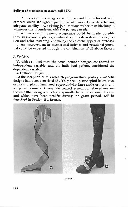
(1) Plastic Spiral Below-Knee Orthosis (Fig. 1 a and b) (12). The Spiral Below-Knee Orthosis (BKO) is an energy-converting
adjunct to the foot-ankle complex. It is designed to: (a) Maintain the natural architecture of the foot. (b) Apply a stabilizing three-point force system on the foot-ankle
complex. (c) Allow for and control transverse rotation, plantar flexion and
dorsiflexion. (d) Convert the inertia of the body into kinetic and potential
energy where and when needed by the foot-ankle complex to provide for an efficient gait pattern in terms of cosmesis and energy consumption.
(e) Allow for interchangeability of standard shoes, as it is worn inside the shoe.
Studies of normal human locomotion have shown that transverse rotation is an important component (9,lO). The magnitude of transverse rotation may be considerable, consisting of as much as 30 deg. of relative rotation between the pelvis and the foot (11). An important characteristic of the spiral orthosis, its capacity to wind and unwind, permits adaptation to the normally significant degree of transverse rotation (a motion not generally found in the design of conventional below-knee orthoses). Consequently, it provides for controlled motion in all planes, that is, it adapts to transverse rotation as well as to motions in the frontal and sagittal planes.
The spiral configuration as applied to orthotics represents a new and unique concept which obviates the need for any metallic joints in the orthosis. This is possible because of the unique energy and force systems it represents. It aids in the transfer of potential energy to kinetic energy and back to potential energy. This appears analogous to human function (12), allowing sensitive, continuous control over the lower leg throughout the entire gait cycle. Most of the unwinding, that is external rotation of the superstructure on the foot, occurs during the stance phase. On heel strike the spiral unwinds to allow controlled deceleration of the plantar-flexing foot. From foot-flat to midstance the forward motion of the tibia is assisted by the spiral as it returns to its unstressed position. From midstance to heel-off the spiral is being dorsiflexed by the forward movement of the tibia, and energy is stored which is released during the period of heel-off to toe-off. Thus, the spiral assists in push-off until it reaches its neutral position. During swing phase, the internal resistance of the orthosis acts to assist toe clearance by preventing plantar flexion. Controlled eversion and inversion are inherent in the spiral configuration and must include the shoe as an integral part of that configuration.

Bulletin of Prosthetics Research-Fall 1973
The plastic spiral BKO is made from an amber-colored thermo- plastic acrylic-nylon composite, weighing approximately 200 gm. The spiral portion of the orthosis originates from the medial side of a foot plate, passes around the leg posteriorly, and terminates at the level of the medial tibia1 flare. A horizontal band is attached to the spiral at a point 20 mm. below the fibular neck.
(2) The Supracondylar Knee-Ankle Orthosis (Figure 2 a and b) (8)- -
FIGURE 2
The Supracondylar Knee-Ankle (SKA) Orthosis is a substitute for the conventional long leg brace with knee lock in selected patients. It is designed to:
(a) Permit free knee flexion in the swing phase. (b) Provide a knee extension moment in the stance phase. 4
(c) Rigidly control the foot and ankle in all planes. (d) Control the knee mediolaterally. ( e ) Prevent knee hyperextension. (f) Allow for interchangeability of shoes. This orthosis constitutes a modification of the PTS prosthesis (13)
with above-knee prosthetic alignment principles to provide knee stability in patients who lack knee extensor strength as well as motor power about the ankle. This is achieved by immobilizing the ankle and foot in equinus with a laminated plastic orthosis extending to

Lehneis et al.: Bioeng. Design and Devel. of LE Orthoses
the supracondylar knee area. T h e equinus attitude results in alignment stability, producing a knee extension moment in the stance phase, eliminating the need for a mechanical knee lock. Genu recurvatum is effectively controlled by the anterior extension above the knee, counteracted by a force applied in the popliteal area. Mediolateral stability of the knee is assured by the supracondylar extensions.
The SKA orthosis is a unitized structure made of a flesh-colored w
polyester laminate, reinforced with nylon fibers and fiber glass, weighing approximately 400 gm. This produces a closer-fitting and more cosmetically acceptable orthosis. Furthermore, free knee flex- ion in the swing phase not only results in a more nearly normal gait pattern, but conceivably in a reduction in energy consumption.
(3) Hydra-pneumatic Knee-Ankle Control System (Figure 3 a and b) (14).
T h e Hydra-pneumatic Knee Ankle Control System is a unit . incorporated in an above-knee orthosis to coordinate knee-ankle motions. It is designed to:
(a) Provide automatic and adjustable swing phase control. (b) Provide knee stability against buckling from heel strike to
midstance. (c) Decelerate the foot to prevent foot slap, i.e., damping of heel
strike.

Bulletin of Prosthetics Research-Fall 1973
This system provides stability of the knee during the critical period from heel strike to midstance phase of gait. At the same time it offers controlled fluid resistance to plantar flexion. Plantar flexion causes the hydraulic fluid in the cylinder to be displaced upward, resulting in an extension moment about the knee joint. This reciprocating action also comes into play in the swing phase, where knee flexion produces dorsiflexion of the foot. A 90 deg. dorsiflex- ion stop is used for standing stability and to substitute for push-off. . In allowing controlled knee flexion, a more nearly normal pattern of gait, as well as a reduction in energy consumption, is presumably achieved.
b. Patient Conditions Although a given orthosis is designed to constitute a certain force
system, the effect it causes depends on the patient's condition, both physical and psychological. Physically, they are dependent on resid- ual motor power, degree of spasticity, and sensory status. Psychologi- cally, variables are introduced beyond the patient's physical condi- tion, such as motivation, attitude, and adjustment.
3. Methods of Evaluation
The methods employed to study the effects on patients caused by the application of the orthoses were:
a. Patient Data and History b. Physical evaluation consisting of: (1) Muscle test (including degree of spasticity). (2) Active and passive range of motion. (3) Gait analysis without an orthosis, conventional brace when
applicable, and with the new orthosis. (4) Functional evaluation (under the same conditions as (3) above). c. Objective, photokinematic analysis without an orthosis,, with a
conventional brace if applicable, and with the new orthosis. d. Oxygen consumption studies, with old and new orthotic devices. e. Psycho-social and vocational rating scales.
D. Data Collection and Analysis
1 . Patient Data and History
Every patient included in this study was evaluated at either the orthotic out-patient or the two in-patient clinics by the physician, orthotist-engineer, and physical therapist, and an appropriate or- thosis was prescribed. Patient data and history were recorded by the research physical therapist on a form shown in Appendix B 1.

Lehneis et 01.: Bioeng. Design and Devel. of LE Orthoses
2. Physical Evaluation
A specially designed form (Appendix B2) was used to serve as a base line for comparison following orthotic fitting. This represents a . completely new approach to a combined physical and orthotics evaluation and includes range of motion and muscle test as well as angular attitude of the leg segments as viewed in the frontal, sagittal, and transverse planes. Thus, the patient's muscle picture, range of .- motion, and angular attitude at any particular leg segment can be viewed almost simultaneously on this chart. This not only simplifies the actual patient evaluation but also reduces the number of forms normally necessary in assessing the patient's physical status. Gait and functional evaluations, including activities of daily living, were performed without an orthosis, with a conventional brace, when applicable, and with the new orthosis and results were recorded (Appendix B3 & 4).
3. Photokinematic Analysis
Normal subjects as well as patients who had been fitted with the spiral BKO and who had previously worn conventional below-knee orthoses were selected for this study. Markings were made on the affected limb laterally at the trochanter, knee center, malleolus, and along the border of the foot; frontally at the suprapatellar border and tibia1 crest; and posteriorly along the centerline of the limb, orthosis, and shoe.
First, the subject walked 20 ft. from the camera (Minolta autopak- 8 D 10 with maximum speed capability of 50 frameslsec and 7-70 mm. lox variable speed power zoom) with the lateral side of the affected limb facing the camera. Zoom was adjusted so that only the limb filled the screen. Second, the subject walked toward and away from the stationary camera with the automatic zoom continually adjusted so that the portion of the body under consideration was always of maximum size on the screen. Most of the measurements taken were angular, rather than linear, to discount magnification as a variable.
Linear measurements were taken in the analysis of transverse rotation. I n this instance a treadmill with variable speed and automatic elevation was employed and the camera placed at a fixed distance to take a posterior view (Fig. 4). The treadmill was kept at a constant speed throughout for the individual subject. The data were analyzed by running the film on an adjustable speed projector (De Jur Remote Command 86 AZR) with single frame capability so that each frame could be studied and the angular and linear relationships between the patient's thigh, shank, and foot in the frontal and sagittal planes could be measured, as well as the displacement of the

Bulletin of Prosthetics Research-Fall 1973
conventional and spiral orthosis with regard to the patient's extrem- ity.

Lehneis et al.: Bioeng. Design and Devel. of LE Orthoses
In addition, video tape recordings were made of two selected patients to graphically record the differences in gait patterns walking without, with a conventional, and with the new orthosis.
. 4 . Energy Expenditure Study
The method employed was to collect and analyze the expired air of subjects wearing various orthoses. The quantity of consumed oxygen was used as the basis for comparison. A portable collection
C
unit was fitted to the subjects and the expired air was taken as the subjects walked on level ground during 2-minute intervals, with 5- minute rest periods before each run (Fig. 5). Immediately before the samples were taken, the subjects walked to establish a steady state of

Bulletin of Prosthetics Research-Fall 1973
respiration. The distance traveled during the 2-minute interval was noted. The subjects were instructed to walk at the most comfortable rate. A treadmill was not employed as it was felt that confining an individual to a standard walking rate not determined by himself would be more harmful to the study than the walking of a non- standard distance at a most comfortable rate. In order to compen- sate for this non-standard distance, oxygen consumption values were compared per unit distance, as well as per unit time. The equipment .. used was:
a. Collection unit: (1) Rubber mouthpiece connected to (2) Acrilic plastic two-way J-valve, model #P-307, Warren. E.
Collins, Inc., to direct air through flexible hose to (3) Stopcock, Model #P321, Collins, to permit expiration to
atmosphere prior to collection run and sealing off of (4) Douglas collection bag which is harnessed to back of subject. b. Analysis unit: Expired air from the Douglas collection bag is fed into the analysis
unit which consists of the series connection of three separate devices (Fig. 6). These devices collect the raw data that are necessary for the solution of the first equation or quantity of oxygen consumed.
(1) Volume meter (Precision wet test gas meter, Precision Scientific Co.) which measures the entire volume of expired air. '
(2) Carbon dioxide meter-Godart Capnograph, which determines

Lehneis et al.: Bioeng. Design and Devel. of LE Orthoses
the percent of COz in the expired air by comparing with sample, enabling readouts to appear in a matter of seconds.
(3) Oxygen meter---Godart Rapox, which determines the percent of oxygen by the same principle as the COz meter. .
T o determine the quantity of oxygen consumed in each run from the raw data of expired volume, percent oxygen and percent carbon dioxide, the following equations were employed:
Vo2 = volume/minute of oxygen consumed (milliliterlminute)
Ve = volumelminute of expired air (mllmin) FeN2 = fraction of nitrogen in expired air
fraction of expired oxygen + = I - [
fraction of expired carbon dioxide 1 FiNl = fraction of nitrogen inspired = .79 = constant Fiol = fraction of oxygen inspired = .21 = constant
Feo2 = fraction of expired oxygen
Since the runs for the different subjects were conducted on different days it became necessary in certain comparisons to introduce a temperature and barometric pressure correction factor. The rela- tionship employed was as follows:
Vo2 std = (A) Vo2
where
V,, std = standardized volumelminute of consumed oxygen (mllmin) v ~ 2 = vollmin oxygen consumed (mltmin) - A = temperature and barometric pressure correction factor deter-
mined by a standard table.
Since each subject walked a slightly different distance during each 2- minute run, standardization of distance is also necessary to compare subjects on an equal basis. These values are listed in the tabulated results by means of the following relation:
VO, std distance

Bulletin of Prosthetics Research-Fall 1973
with units of mumin, meter. The distance referred to is the total distznce traversed by the subject during the 2-minute run.
It is the above value that is used to compare consumed oxygen using the spiral and conventional orthosis with the following:
5. Psycho-social and Vocational Evaluation
VO, std distance
Data for this study were collected by two methods. T h e first method was by means of two sets of questionnaires sent to patients by mail. The first set was sent to conventional and to new device wearers only (Appendix Cl) . The second set was sent to the patients who had previously worn conventional braces and were now wearing a new device for the purpose of comparison (Appendix C2). The questionnaires were designed to survey the patient's verbal responses of his performance which are related to his psycho-social attitude toward the orthosis, as well as his functional change resulting from these fittings.
The patients selected were all non-acute and only below-knee orthosis wearers. The study was confined to this category in order to approach the greatest degree of statistical validity. The question- naires are not of the objective variety, but rather employ a subjective functional approach where the patient's value judgments relating to the orthosis and his capabilities are elicited. Although there may be discrepancies between actuality and verbal response, this type of questionnaire, which included counterbalanced multiple choice items, as well as a global essay type question to evaluate the present mood of the patient, provided the most practical means of surveying this patient population. In the analysis of the questionnaires the questions were grouped in four categories: comfort, convenience,
VO, std conv. - d exp.
Percent - - difference x 100%
VO, std d conv.

Lehneis et 01.: Bioeng. Design and Devel. of LE Orthoses
cosmesis, and function. The answers were subdivided into negative, neutral, and positive responses and were added up under each category.
A second method was developed in consultation with and partici- pation of the Department of Behavioral Sciences (Dr. Diller), to determine what effect the spiral BKO has on a patient's vocational adjustment in society. The methods employed were a rating scale (Appendix E 1 & 2), personal interviews, and clinical observations. The categories rated were looks, usefulness, comfort, and conveni- ence. A space provided under each category for a written explana- tion as to why the patient rated each category as he did. It was considered that meaning relative to vocational adjustment could be defined as: "Looks," referring to the psychological image one has of himself, usefulness, comfort, convenience relating to improved physical ability. Patients were asked to mark the rating scale for each category from 0 (neutral) to +7.8 crns. on the positive (right) side for the highest possible rating and to -7.8 crns. on the negative (left) side for the lowest possible rating. The rating in each category was measured, recorded, and tabulated. The purpose of the clinical observation and excerpts of the written comments was to determine whether the rating was indeed vocationally pertinent. If this was found not to be the case, the patient's rating was placed in a category labeled diffuse positive (D+) or diffuse negative (D-).
Ill. RESULTS
In accordance with the original grant proposal, the general plan was to finalize the design of the three prototype orthoses through bioengineering analyses; expanded patient fittings and evaluation to establish definitive indications for each of these devices and to serve as in-put for any design changes necessary to match the various disability categories with an appropriate biomechanical system; and to evaluate objectively the effectiveness of these devices.
A. The Plastic Spiral BKO
Although the basic helical configuration of this orthosis has remained unchanged from its original conception, several refine- ments have been made during the period. They relate to improve- ment in fit and comfort, standardization of procedures, materials, and techniques. The results of this and of a periodic evaluation and check-up are presented.
Bulletin of Prosthetics Research-Fall 1973
1. Improvement in Fit
Modifications relating to fit occurred primarily in the area of the calf. It was found that the initially circular and semi-rigid calf closure did not provide the patient with sufficient resistance against foot slap and rotational control. The calf band was therefore modified to provide a triangular cross-sectional shape, quite similar to that found in below-knee prostheses. This resulted in vastly improved rotational control and comfort. The material and thickness 1
is the same as that used for the spiral itself. This led to the standardization of the patterns as a two-component unit, allowing for pre-fabrication of a flat footplate-spiral unit and separate calf band which, after molding, is joined at the appropriate individual height to the spiral by means of shrink-expansion rivets. It was found that two widths of the helical upright, i.e., 4.5 cm. and 5 cm. were adequate for most applications.
2 . Standardization of Procedures
Standardized procedures and techniques for casting, fabricating, and fitting were made possible, in particular by the development of three casting boards for 2.5 cm., 3.5 cm., and 4.5 cm. heel heights. They are an important adjunct to proper casting methods and assure better fit and alignment not only with respect to the extremity but the patient's shoe as well. A vertical alignment rod may be inserted on either side of the board to serve as a reference line for the alignment of the shank in the frontal and sagittal planes. Details of these and other procedures are found in the fabrication manual Plastic Spiral Below Knee Orthosis (listed in Appendix F). 3. Materials and Techniques
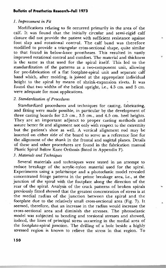
Several materials and techniques were tested in an attempt to reduce breakage of the acrylic-nylon material used for the spiral. Experiments using a polai-iscope and a photoelastic model revealed concentrated fringe patterns in the prime breakage area, i.e., at the junction of the spiral with the footplate along the direction of the rear of the spiral. Analysis of the crack patterns of broken spirals - previously fitted showed that the greatest concentration of stress is at the medial radius of the junction between the spiral and the footplate due to the relatively small cross-sectional area (Fig. 7). It seemed, therefore, that an increase in the radius would increase the cross-sectional area and diminish the stresses. The photoelastic model was subjected to bending and torsional stresses and showed, indeed, the lines of principal stress occurring in the medial area of the footplate-spiral junction. The drilling of a hole beside a highly stressed region is known to relieve the stress in that region. To

Lehneis et al.: Bioeng. Design and Devel. of LE Orthoses
FIGURE 7 FIGURE 8
confirm the above in this particular application, a photoelastic model was prepared to represent the design with the full footplate. An identical model was tested with the exception of a hole drilled beside the region of known high stress. It was observed via isochromatic fringe patterns that stress is lessened in the model with the hole. This analysis led to the redesign of the spiral BKO by actually completely eliminating the heel section of the orthosis (Fig. 8). This not only provided for improved sensory feed-back at heel strike but reduced breakage as well. For the purpose of testing this modifica- tion as well as other materials and methods, a cycling machine was developed. T h e objective of the design of the machine was to construct a device which would, as closely as possible, duplicate normal motion of the foot and ankle complex during locomotion. The assumption was that the plastic spiral BKO conforms to normal locomotor patterns. The design objectives were therefore imple- mented by adapting the orthosis so that it in itself serves as the core or principal control element in the testing machine, thus eliminating complex linkages and joints. The method employed was to promote unrestrained movement of the spiral by supporting the footplate and to move the spiral portion with a linkage fastened to a universal joint. This system includes a commercial sequence programer which employs two-way valves, making it possible to test as many as four . spirals simultaneously. Specifically, a double-acting pneumatic cylin- der is equipped with universal joints at either end. The non-moving portion is attached to the rigid base via an adjustable clamp and the moving portion of the cylinder attached to the spiral portion of the - orthosis. The power to move this system is supplied by a 50 p.s.i. central air compressor system. The control system consists of an electric motor which serves in a timing capacity, as well as to turn the cams which operate the pneumatic valves (Fig. 9). Three spirals were tested not only to obtain data regarding the breakage point, but also to test the validity of the cycling machine in terms of

Bulletin of Prosthetics Research-Fall 1973
simulating the stresses imposed on the spiral during patient ambula- tion. The breakage patterns in the first two spirals were indeed similar to those occurring from patient wear. The first spiral which did not include a heel and represents the newer design version broke at 2,032,240 cycles, a very definite improvement over the original design. The third spiral, also without the heel section, did not break after 4,888,000 cycles, and cycling was terminated. In spite of these encouraging results 7 to 8 percent of the orthoses applied clinically broke within a period of 12 months. This is likely due to the fact that the cycling machine did not employ overstressing, such as occurs when one walks down stairs or squats. Breakage, when it does occur, initiates between the junction of the footplate and spiral portion and the first turn of the spiral, approximately 10 cm. proximal to the footplate at a corner of the posterior edge. From '*
observation of numerous breakage patterns, noting cycling machine results, bench tests, time required for breakage occurs because of the combined effect of overstraining the material and fatiguing. Fatigu- ing, however, is not the primary failure, as properly tempered spirals have been cycled 5,000,000 times without breaking. Neverthe- less, what actually occurs is that the material, at one time or another, is overstressed, or the elastic limit of the material is exceeded momentarily which is not apparent at the time of occurrence. Subsequent repeated cycling causes this overstrained region to strain

Lehneis et al.: Bioeng. Design and Devel. of LE Orthoses
even more until failure occurs days or even months after the overstrain was introduced. Thermoplastic molecular chains, of which the material is composed, are not cross-linked like thermoset chains and will slide past one another when they can no longer uncoil- uncoiling and recoiling occurs below the elastic limit, and relative sliding, an irreversible state, occurs beyond the elastic limit. Several avenues were followed to reduce the breakage problem further. These were radiation treatment, heat treatment, improved molding procedures, and testing of other materials.
a. Radiatior? treatment Radiation is known to cause chemical linking of polymers to
increase material strength, although not all plastic materials can be strengthened in this way. Briefly, this method consists of the exposure of the material to gamma rays in conjunction with the emersion of the specimen in a bath containing the molecules which can be selectively grafted to the polymer chains. Although this grafting procedure was successful, the material thus treated no longer possessed its excellent non-creep property, i.e., its modulus of elasticity was lowered to a point where it no longer performed satisfactorily in the spiral BKO application. The procedure was therefore discontinued.
b. Heat treatment Heat treatment experiments to be valid must be performed on the
plastic under consideration, as plastics vary in their reaction to heat. Plexidur," the material used in the orthosis, while photoelastic is not sufficiently so to perform an exclusively photoelastic approach experiment. Qualitatively, the photoelastic observation of Plexidur indicates a reduction of residual stress following heat treatment. In order to obtain a more nearly valid result of stress relief in Plexidur through heat treatment a special experiment was performed. A sample strip was twisted 180 deg., after softening, and held in a fixed position. I t was then placed in an oven a t the molding temperature of 140 deg. C. for 20 minutes. The restraint was then removed while still hot in the oven, resulting in the twist relaxing to 45 deg. Another strip was subjected to a similar treatment except at a temperature of a 110 deg. C. for 4 hours. In this sample the twist relaxed to only 30 deg. The results of this may be interpreted as a residual stress relief in the first sample of 25 percent compared to 16.7 percent in the second sample. It appears then that annealing of the material at the molding temperature produces the best result in terms of stress relief in this case. Annealing the material at the molding temperature presented, however, great technical problems
Rohm and Haas Company, Darmstadt, Germany.
Bulletin of Prosthetics Research-Fall 1973
because the molded spiral would lose its shape unless both spiral and cast could be placed in the oven with the spiral held firmly against the cast. Through correspondence with the manufacturer it was found that an annealing process was possible at a temperature lower than that required for molding (see Spiral Manual for details). This method of stress relief has since been successfully employed.
c. Molding procedures Molding procedures were improved to avoid the possibility of
stress inducement when the plastic was molded over the cast. A pre- heated cast increases working time for molding but presents the problem of brittleness and cracking. This problem has been gfeatly reduced by mixing one part of microballons to 20 parts of plaster per volume when the positive cast is poured. The addition of the microballon also appears to enhance heat retention in the mold.
d. Other materials OrtholenP a flesh colored high molecular weight polyethelene was
tested but not found satisfactory because of its poor molding and creep characteristics, not retaining the shape of the model it was molded over. Two other materials are presently undergoing evalua- tion, but results have been inconclusive so far. They are polypropyl- ene and advanced composite materials. In order to obtain adequate stiffness of the spiral the polypropylene material had to be increased in width and thickness by 25 percent. As of the writing of this report, cycling testing has not been completed. The advanced composite materials tested are those which employ materials such as carbon fibers and fiber glass embedded in a matrix such as polyester, epoxy or polypropylene. None of these materials has, so far, shown to possess the characteristics so successfully employed in the performance of the spiral BKO and made possible with the acrylic-nylon composite. Another version of the acrylic-nylon com- posite known as Sadurc has been successfully applied and seems to possess, in fact, somewhat superior characteristics in terms bf strength, ease of molding, and color being somewhat more translus- cent than Plexidur. As a result of these investigations, breakage has been reduced to a minimum in unilateral applications, though breakage in bilaterals is still a problem to be solved.
4 . Periodic Evaluation and Check-up
A periodic check-up of spiral BKO wearers was undertaken to determine maintenance of fit, gait, muscle strength, range of motion, and general satisfaction over a period of time. Of 57 patients contacted, 43 were scheduled and evaluated. The length of time these patients had worn an orthosis was from 3 months to 3
W. J. Teufel Company, Stuttgart, Germany.

Lehneis et 01.: Bioeng. Design and Devel. of LE Orthoses
years. Each patient was reevaluated, using the forms listed in Appendix B, and the fit and general satisfaction with the orthosis was checked. The results of this reevaluation were:
a. There were no appreciable losses in ROM or muscle strength other than in patients with progressive disorders.
b. Two hemiplegic patients exhibited an increase in spasticity at the ankle. Hemi-spirals were subsequently prescribed in both cases.
c. No patient seen was dissatisfied or was not wearing the device. d. Patients with severely atrophied extremities required more
adjustments due to bony protuberances, particularly on the medial and lateral border of the foot.
e. Several patients reported that after 6 months or a year, the Plexidur became unevenly discolored from wear and was not cleanable.
f. No spiral was found to have changed in alignment and shape from the original fitting.
g. No patient would consider returning to the conventional BKO, including those who have had breakage problems.
From this patient population 10 subjects were selected for a comparative gait evaluation. Selection was based on representative- ness of the total by type of disability, age, sex, height, weight, and length of time of spiral usage.
Each patient's gait analysis was recorded on the Gait Analysis Form (Appendix B3) without device, conventional and spiral BKO. Gait deviations were graded according to severity, i.e., extreme, moderate, or slight. The number of gait deviations were then plotted against each of the conditions studied as shown in Figure 10. I t will be noted that the spiral BKO eliminated extreme gait deviations completely and 82.4 percent moderate gait deviations. These results indicate that significant improvement in gait patterns is achieved by the spiral BKO in patients with diverse disorders, both upper and lower motor neuron lesions, all ages, heights, and weights, when compared with a conventional BKO.
B. Supracondylar Knee-Ankle (SKA) Orthosis
Ten patients were fitted during the period with 'the SKA orthosis. Of these, one patient discontinued using the orthosis following reconstructive surgery. Another patient required the addition of knee joints, locks, and thigh shell, since she was unable to safely ambulate with the SKA orthosis. After close examination it was found that this patient did not have active hip extensors on the involved side, nor good hip extensors on the contralateral side. There was also a slight hip and knee flexion contracture on the

Bulletin of Prosthetics Research-Fall 1973
K E Y = SLIGHT DEVIATIONS
= MODERATE DEVIATIONS
= EXTREME DEVIATIONS
NO DEVICE CONVENTIONAL SPIRAL
involved side. This, as well as other patient fittings, although not extensive, led us to deduce the general indications and contraindica- tions for this orthosis. Indications are for unilaterally involved patients who lack motor power in the ankle and knee extensors. Structural knee instability, especially in the direction of genu valgum and genu recurvatum, is no contraindication. As a matter of fact, most patients fitted in this study exhibited genu recurvatum and valgum at the time of the initial evaluation. Yet, correction was achieved in all cases, while stabilizing the knee against buckling. C
Contraindications are bilateral involvement, presence of edema or fluctuating leg size, presence of knee and hip flexion contractures, and the absence of hip extensors, at least on the involved side.
Case Presentation J.S. is a 67-year-old male who acquired polio as a young child. He
was seen at the Out-Patient Clinic with the chief complaint of instability of the knees, particularly the left, so much so that it hindered his safety in independent ambulation. He felt he was becoming more and more dependent on his family and sought help.
Lehneis et al.: Bioeng. Design and Devel. of LE Orthoses
Muscle strength tested on the left was: P hip flexors and rotators with F+ extensors and abductors, P quads and F-hamstrings, and 0 musculature at the ankle. ROM revealed 40 deg. genu recurvatum with 15 deg. genu valgum. The ankle was held in a talipes equinus
0
attitude. The patient had never had any orthotic device but had always used Lofstrand crutches. Gait pattern exhibited on the left severe recurvatum and valgum, lateral and anterior trunk bending,
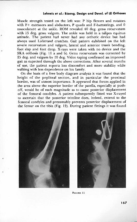
C foot slap and foot drop. X-rays were taken with no device and the SKA orthosis (Fig. 11 a and b). Genu recurvatum was corrected by 25 deg. and valgum by 10 deg. Video taping confirmed an improved gait as expected through the above corrections. After several months of use, the patient reports less discomfort and more stability while walking with less dependence on his family.
On the basis of a free body diagram analysis it was fo,und that the height of the popliteal section, and in particular the proximal border, was of utmost importance. It appeared that forces applied in the area above the superior border of the patella, especially at push- off, would be of such magnitude as to cause posterior displacement of the femoral condyles. A patient subsequently fitted was X-rayed to ascertain that the posterior trimline does, indeed, extend to the femoral condyles and presumably prevents posterior displacement of the femur on the tibia (Fig. 12). During patient fittings it was found

Bulletin of Prosthetics Research-Fall 1973
that the suprapatellar extension required modification, especially for male patients because of the proximal protrusion in 90 deg. of knee flexion. This solid section was therefore lowered and replaced with a flexible strap. The strap was attached to the medial and lateral extensions by means of a swivel joint, so that it could conform to the motions of the knee. With this modification, reinforcement of the medial and lateral extensions with aluminum bars in the lamination was needed, since without this the extensions flexed toward the extremity when pressure was exerted against the strap, causing discomfort mediolaterally and a reduction of hyperextension control. Although these modifications are necessary in male patients, females preferred the original design of a unitized structure. Apparently, the additional thickness, weight, and bulk of a strap were found objectionable and far less cosmetic than some protrusion in sitting which, of course, in female patients is of no consequence, except when wearing slacks. Addition of knee joints to separate the suprapatellar extension from the rest of the orthosis was attempted, but was not totally satisfactory since the extension stop of the knee joints produced noise and the addition of the joints required a greatly reinforced laminate which resulted in a rather heavy device.
A development resulting from the analysis of the free body diagram of the SKA orthosis, in conjunction with patient fittings, led to the conception of a casting and alignment jig (Fig. 13). This

Lehneis et al.: Bioeng. Design and Devel. of LE Orthoses
device is used to test the feasibility of the SKA concept in patient candidates. It is totally adjustable and allows the determination of the angular relationship between the foot and the shank and the degree of knee extension required for optimum stability prior to casting. A knee extension angle of 180 deg. during casting was found the most effective since suprapatellar tissue compression would allow a few additional degrees of knee extension. These additional degrees of knee extension, the amount of which is dependent upon tissue consistency, provide for necessary knee stability during stance phase. The optimum angular relationship between the foot and shank was found to be largely determined by the stride length of the individual. Patient evaluations showed, however, that the angular relationship between foot and shank did not vary to such a degree as to justify trigonometric calculations for each patient. A fixed equinus attitude resulting in a clearance of 1 cm. between shoe heel and floor in midstance permits a normal stride length while avoiding heel strike, thus providing a knee extension moment, the main design concept of the SKA orthosis. If no length discrepancy is present, removal of .5 cm. from the heel of the shoe and a .5-cm. build-up on the sound side is necessary. T o aid in patient evaluation with the SKA orthosis, a check-out form was developed (Appendix D).
C. Hydra-Pneumatic Knee-Ankle Control System
Because of the concentration in the spiral BKO and SKA fittings, as well as new developments described below, only one patient was fitted with the hydra-pneumatic knee-ankle control system. T h e subject selected was a post-polio patient who had been wearing a conventional long leg brace with knee lock since early childhood. Although the patient's performance was quite satisfactory and he did not experience any knee instability, he discontinued wearing the new orthosis, stating that he is so accustomed to ambulating with a locked knee that he could not get accustomed to the increased motion permitted in the hydra-pneumatic control system. I t appears that because of the other developments, the number of candidates for the hydra-pneumatic control system is quite limited, since there are other devices of choice which may be employed instead.
Considering the hydra-pneumatic orthosis in a more technical vein, the equilibrium rule for physical bodies, of course, is implicit in all of the orthoses. The optimum moment arm ratio in the hydra- pneumatic orthosis as such could not be determined in this manner with any facility because of the enormously complex dynamic force system during gait. Therefore, the following deductions were made:
Bulletin of Prosthetics Research-Fall 1973
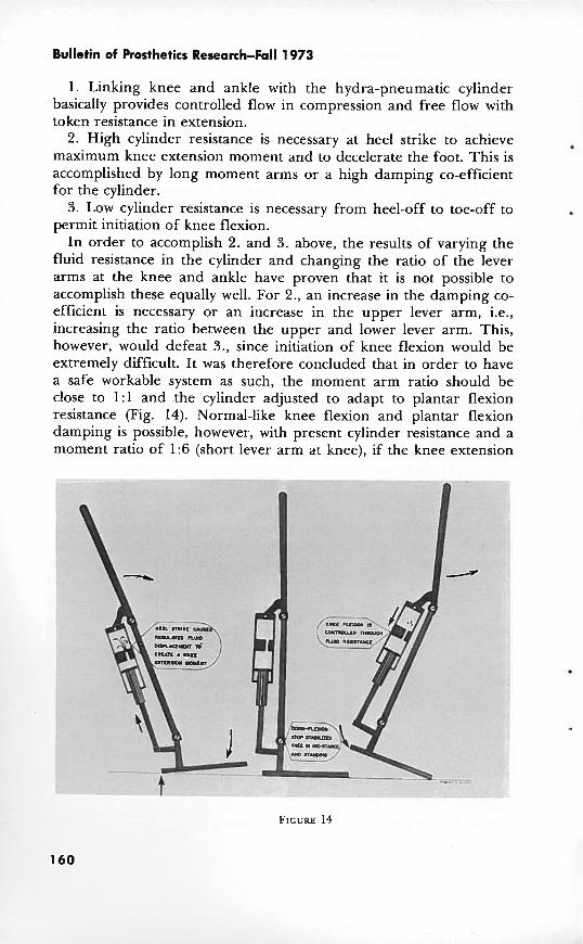
1. Linking knee and ankle with the hydra-pneumatic cylinder basically provides controlled flow in compression and free flow with token resistance in extension.
2. High cylinder resistance is necessary at heel strike to achieve . maximum knee extension moment and to decelerate the foot. This is accomplished by long moment arms or a high damping co-efficient for the cylinder.
3. Low cylinder resistance is necessary from heel-off to toe-off to permit initiation of knee flexion.
In order to accomplish 2. and 3. above, the results of varying the fluid resistance in the cylinder and changing the ratio of the lever arms at the knee and ankle have proven that it is not possible to accomplish these equally well. For 2., an increase in the damping co- efficient is necessary or an increase in the upper lever arm, i.e., increasing the ratio between the upper and lower lever arm. This, however, would defeat 3., since initiation of knee flexion would be extremely difficult. It was therefore concluded that in order to have a safe workable system as such, the moment arm ratio should be close to 1:l and the 'cylinder adjusted to adapt to plantar flexion resistance (Fig. 14). Normal-like knee flexion and plantar flexion damping is possible, however, with present cylinder resistance and a moment ratio of 1:6 (short lever arm at knee), if the knee extension

Lehneis et al.: Bioeng. Design and Devel. of LE Orthoses
moment can be reduced in patients who have normal hip extensors which can aid in stabilizing the knee.
D. Other developments
As a result of greatly expanded patient fittings it was found that the three devices described above would not adequately fulfill all patient needs if, as stated in the introduction, the orthosis is designed to only minimally inhibit normal motions. In other words, if one wants to avoid overbracing, as well as underbracing, other designs need to be developed to provide orthotic management in all patient disability categories. The variety of clinical problems seen in the Out-Patient Lower Extremity Orthotics Clinic and from other services has resulted in rather prolific activity in new orthotic design and development. I t has shown some limitations of the three prototypes in meeting .all clinical entities which require orthotic management. Yet, the three prototypes have served as the basis for spin-offs for new orthotic devices.
1 . Hemispiral Below-Knee Orthosis
Although it is believed that the original spiral design conforms to normal gait patterns, it does not necessarily meet the problems of patients exhibiting abnormal gait patterns, such as the hemiplegic patient. In the hemiplegic patient with moderate to severe spasticity the original spiral configuration does not offer adequate resistance to the deforming forces produced by the patient's equino-varus tendency. T o solve this clinical problem it became apparent that the location of required corrective forces necessitated the reversal of the spiral configuration as well as a reduction of the spiral helix by one half to provide increased resistance against equinus.
While the design of the calf band remained the same as in the original spiral design, the footplate and the point of origin of the spiral were changed.
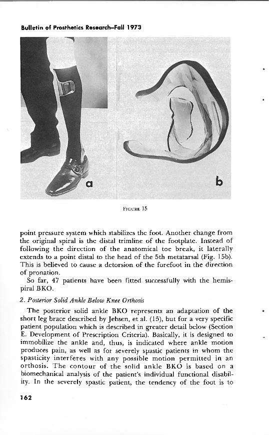
The footplate was designed to hold the foot in such a way as to prevent forefoot adduction and supination, as well as varus. It incorporates a.n anterior medial flange which fits snugly behind the head of the first metatarsal and a posterior flange which covers the medial portion of the calcaneus. The spiral section, rather than originating medially, originates on the lateral aspect of the footplate, winds around the leg posteriorly, and terminates medially in the area of the medial tibial flare, where it is attached to the triangularly shaped calf band (Fig. 15a). The spiral exerts pressure against the distal half of the fibular shaft, constituting the medially directed force, and with the two laterally directed forces at the medial tibial flare and the medial flanges of the footplate, completes the three-
Bulletin of Prosthetics Research-Fall 1973
v -.
point pressure system which stabilizes the foot. Another change from the original spiral is the distal trimline of the footplate. Instead of following the direction of the anatomical toe break, it laterally extends to a point distal to the head of the 5th metatarsal (Fig. 15b). This is believed to cause a detorsion of the forefoot in the direction of pronation.
So far, 47 patients have been fitted successfully with the hemis- piral BKO.
2 . Posterior Solid Ankle Below Knee Orthosis
The posterior solid ankle BKO represents an adaptation of the short leg brace described by Jebsen, et al. (15), but for a very specific patient population which is described in greater detail below (Section E. Development of Prescription Criteria). Basically, it is designed to immobilize the ankle and, thus, is indicated where ankle motion produces pain, as well as for severely spastic patients in whom the spasticity interferes with any possible motion permitted in an orthosis. T h e contour of the solid ankle BKO is based on a biomechanical analysis of the patient's individual functional disabil- ity. In the severely spastic patient, the tendency of the foot is to

Lehneis et al.: Bioeng. Design and Devel. of LE Orthoses
assume an equino-varus attitude. It is therefore necessary to apply a force system similar to that described for the hemispiral BKO above, but more rigidly. Thus, the laminate is contoured to extend medially to the tibia1 flare, provide support behind the head of the first metatarsal and the medial portion of the calcaneous, counteracted by a force above the lateral malleolus (Fig. 16 a and b). As viewed in the sagittal plane, the trimline laterally extends anterior to the mid- line to provide effective support, and viewed medially, the proximal termination also extends anterior to the mid-line, while all other
L
areas may recede posterior to the mid-line. Another indication is for patients who, in addition to equino-varus, suffer from severe proprioceptive loss. It is theorized that in such cases complete . immobilization of the ankle and covering large areas of the extremity may be beneficial, since the foot is held in a pre- determined position and the patient does not have to rely on feedback in controlling his foot. Furthermore, if sensory feedback, even though diminished, is present, it seems possible that the patient may learn to interpret pressures on various areas of the leg induced by floor reaction forces in terms of his foot position. Another

Bulletin of Prosthetics Research-Fall 1973
natural application of this device is in spina bifida patients who suffer complete motor and sensory loss in the ankle-foot area. Here, the stability provided by the solid ankle BKO increases the base of support and, therefore, enhances knee and hip stability. T h e common problem of skin break-down can also be greatly reduced since this device covers a far greater area so that the pressure is reduced. Of course, the fit of this orthosis is superior to that of a conventional brace since it is made from a plaster mold of the patient's limb. Nineteen patients were fitted with the posterior solid ankle BKO. 3. Supracondylar Knee Qrthosis
The supracondylar knee orthosis represents a spin-off from the SKA orthosis. In previous fittings of the SKA orthosis it was found that it not only controls the knee against genu recurvatum, by virtue of its design, but medio-lateral stability of the knee as well. It, therefore, seemed a logical extension to apply the principle of the SKA orthosis in those cases where patients display genu recurvatum and/or medio-lateral instability of the knee but have normal ankle and foot control (Fig. 17 a and b). In the SK design the foot-ankle extension must be replaced with a pre-tibia1 section in the distal half of the shank. The SK orthosis is a unitized structure made of plastic laminate and contains no moving parts. This is of advantage mechanically, but requires diligence in establishing trimlines so that the patient may don the orthosis by first reversing the SK orthosis, i.e., so that the popliteal section points forward until the patient's foot has been threaded through the proximal and the posterior opening below the popliteal area. The orthosis is then rotated 180 deg. and pulled up over the knee. The cosmetic problem with the patient seated is, of course, the same as encountered with the SKA orthosis, although this can be eliminated by lowering the suprapatel- lar extension and replacement with a flexible strap.
Eleven patients were fitted with this device. Two typical cases are presented here. Genu recurvatum was present in both cases but in addition there was genu varum in one and valgum in the other case. Substantial degrees of correction were achieved and are summarized in Table 3 along with those for the SKA and the SK-Spiral orthosis described below.
Case Presentations: a. C.G. is a 22-year-old married female and mother with a
diagnosis of post-polio since childhood. She came to the out-patient clinic from out of state in search of more cosmetic devices. She had been wearing bilateral above-knee braces with drop locks and plantar flexion stops and one Lofstrand crutch on the left. Muscle strength was weaker on the left, being essentially non-functional. The right

Lehneis et al.: Bioeng. Design and Devel. of LE Orthoses
extremity showed G strength at the hip in the extensors with P flexors, abductors, and rotators. The knee showed 0 quads and P hamstrings; the ankle strength was G. ROM revealed severe right recurvatum of 30 deg. with 7 deg. of varum. Gait pattern with the old devices revealed lateral and anterior trunk bending, right varum and recurvatum, and a waddling gait. An SK orthosis was prescribed for the right and an above-knee orthosis for the left. X-rays were taken with and without the SK orthosis. Recurvatum was corrected by 20 deg. and varum was reversed to 5 deg. of valgum, equaling 12 deg. correction (Fig. 18 a and b). Gait appearance was much more acceptable without the gross recurvatum and there was less of a waddling gait. The patient expressed great satisfaction with the cosmetic improvement.
b. C.R. is a 58-year-old male, diagnosed as post-polio since childhood. He came to the out-patient clinic with a complaint of left knee and ankle instability, knee and back pain, and lack of endurance. Because of these difficulties it was becoming more and

Patient
v a TABLE 3.-Angular Measurement of Genu Recurvatum, Valgum, Varum From X-rays %
No Device
40'
15" ----
35 O
15' __ 30'
7O
40°
?a0
With Orthosis --------
15'
5 O
25'
12O - - _ _ _ 1 0°
5' Valgum _ _ _ - I - - -
10°
15'
Orthosis
SKA Orthosis
SK Orthosis
SK Orthosis
SK-Spiral Orthosis
r ; Correction Y)
-- C 0 (P
25' i: n r
l o 0 I a
-- = - l o 0 d
9
3O 3 ----
20°
12O
30"
5 O
Deformity
Recurvaturn
Valgum
Recurvatum
Valgurn
Recurvaturn
Varurn
Recurvaturn
Valgurn

Lehneis et 01.: Bioeng. Design and Devel. of LE Orthoses
more difficult to travel from the suburbs to the city, to his place of employment, and he had to rely on his son more and more to drive him to and from work. Muscle strength tested on the left was F+ to G at the hip, 0 at the knee, and F+ plantar flexors of the ankle, with the remaining ankle musculature 0. ROM revealed severe recurvatum of 35 deg. and valgum of 15 deg. The patient had never used any orthotic device except a knee cage for the past few years. He ambulated with the use of a cane, demonstrating a lordotic posture, marked recurvatum, valgum, and foot drop. T h e SK orthosis and a plastic posterior leaf spring BKO were prescribed. X- rays revealed correction of recurvatum by 30 deg. and of valgum by 5 deg. After 4 months of use, the patient reports less knee and back
b pain and more endurance and stability. He is now able to commute independently to and from his place of business.
4 . Supracondylar Knee-Spiral Orthosis
Patients with structural and neuromuscular deficiencies frequently require a combined application of two or more orthotic devices. For instance, patients who display structural instability at the knee in both the sagittal and frontal planes, i.e., recurvatum, varum or valgum, as well as motor deficits in the ankle, would require assistance of ankle motion and rigid support at the knee opposite to the direction of the deforming forces.

Bulletin of Prosthetics Research-Fall 1973
For these needs the spiral BKO has been combined with the SK orthosis and applied to six patients, including one bilaterally involved. They were four males and two females. Two of the patients' disabilities were due to traumatic injuries, two were post- polio, and the fifth and sixth patient suffered from multiple sclerosis and muscular dystrophy, respectively. The patient with multiple sclerosis, who had previously worn a conventional above-knee brace with knee lock and ankle control, discontinued wearing the device after 6 months because of spasticity, but was subsequently fitted with a solid ankle BK0:All other patients are still wearing the device successfully. One of the other male patients had previously worn a conventional above-knee brace with knee lock. Another male patient, bilaterally involved, had worn bilateral leaf spring braces and elastic knee braces with medial and lateral uprights. One of the female patients had worn a molded leather below-knee brace with rigid ankle. In all patients fitted, the combination of structural control of the knee and flexible assist at the ankle was quite satisfactory. The female patients who had previously worn a molded leather with rigid ankle below-knee brace and had suffered from painful genu valgum, probably aggravated by the rigid ankle, transferring all transverse rotation normally permitted at the ankle to the knee, was quite enthusiastic about the reduction in pain, the light weight, and the ease with which she could ambulate. This, incidentally, was the response of most of the patients fitted.
Case Presentation S.K. is a 64-year-old male with a diagnosis of post-polio acquired
at age one. He was seen at the out-patient clinic with the complaint of severe pain in the left knee joint. Nearly all of his 12-hour working day was spent on his feet, but because of pain was reduced to 6-8 hours. Muscle strength graded on the left G+ at the hip, G quads, F+ hamstrings, and 0 at the ankle. ROM exhibited severe recurvatum of 40 deg. and valgum of 20 deg. A conventional above- knee brace with pelvic band, drop lock, and 90 deg. plantar flexion stop had been prescribed for him 10 years ago, which he wore for 6 months but discarded due to its cumbersomeness and weight. He I
had tried a knee cage but could not keep it in place and did not feel stable with it. The SK-spiral orthosis was prescribed for him. X-rays revealed correction of recurvatum by 30 deg. and valgum by 5 deg. 1
(Fig. 19 a and b). The patient has had the device for 9 months and reports wearing it part of the working day and all day on his days off. He has resumed a 12-hour working day and states that he is only sorry he did not have this device 10 years sooner.
The successful application of this orthosis may be ascribed to the fact that a structural knee control is combined with controlled

---
Lehneis et 01.: Bioeng. Design and Devel. of LE Orthoses
transverse rotation as well as plantar and dorsiflexion, reducing the stresses and often pain at the knee.
5 . Single-Bar Orthoses
As was seen above, the SK orthosis was used as a modular unit in an orthosis for a particular patient problem. This concept of modularity has been expanded to include other clinical problems. If, in addition to the conditions described in 4 above, knee extensor weakness exists, the SK unit may form a modular component in a single-bar below-knee orthosis. As such, it incorporates a dorsiflexion stop to provide knee stability against buckling in the stance phase . and to simulate push-off, and a compression spring to dampen plantar flexion. This orthosis was fitted very successfully to a female patient. . Another application of the SK orthosis as a module is in a single- bar above-knee orthosis. It is indicated for patients in whom the conditions described above prevail but who, in addition, require additional knee stability as provided by a knee lock, as needed in bilateral applications and patients who have weak hip extensors. A further indication for this system is for patients with severe genu valgum and especially varum. In the case of valgum the single bar is

Bulletin of Prosthetics Research-Fall 1973
placed laterally. Thus, the lever arms of the two lateral forces are extended proximally and distally to effectively control this deformity. The medial force over the medial tibia1 flare remains, of course, the same. In cases of varum the single bar is placed medially to extend . the lever arms of the two medial forces. The lateral force required to control varum consists of the sum of two forces, one applied above the lateral femoral condyle, and the other along the shaft of the fibula, since the pressure-sensitive area over the head of the fibula and the lateral femoral condyles of the knee must be by- passed. This constitutes a much more efficient force system because the lateral forces are applied at firm tissue areas superficial to the skeletal structure so that realignment can be effectively achieved. Single-bar orthoses are not only effective as a whole in controlling deformities because of their ease of adjustability, but also offer cosmetic advantages.
Seven patients have been fitted with the single-bar SK orthosis, two with a medial bar varum and five with lateral bar valgum control, i n ~ l u d i ~ g one bilateral. The two patients fitted with the medial bar SK orthosis were one female and one male. The female patient had previously worn a conventional above-knee brace, while the male patient had not worn any orthosis. The absence of the lateral bar and the cosmetic appearance gained from the plastic laminate resulted in enthusiastic acceptance by the female patient. Although the orthosis effectively controlled varum in the male patient, he discontinued wearing it because he felt it impaired his walking. All patients fitted with the lateral bar SK orthosis continued to wear their devices successfully.
Case Presentation S.S. is a 22-year-old female with a diagnosis of post-polio since
childhood. Muscle strength on the right tested as G hip extensors and abductors with 0 flexors and adductors. The knee tested 0 quadriceps and P hamstrings with 0 strength at the ankle other than G plantar flexors. The left extremity also tested G at the hip in the extensors and abductors with 0 flexors. Knee and ankle muscle grades were 0. ROM demonstrated 30 deg. genu valgum on the left and 45 deg. on the right. Genu recurvatum was 25 deg., bilaterally. The right ankle was in equino varus and there was no subtalar motion. The left ankle assumed a valgus attitude. She has worn . bilateral double-bar above-knee braces with knee locks, genu valgum pads, 90 deg. ankle plantar flexion stop on the left with valgus correction strap, and free ankle on the right with varus correction strap (Fig. 20a). She ambulates with Lofstrand crutches and a three- point gait. Her gait pattern with braces exhibits slight to moderate deviations in internal rotation and circumduction, severe genu

Lehneis et al.: Bioeng. Design and Devel. of LE Orthoses
recurvatum and valgum, with equino varus on the right and valgus on the left. Bilateral above-knee orthoses, with lateral single bars, SK units, a left solid ankle and right spring dorsiflexion assist ankle joint were prescribed. With the new devices, recurvatum and valgum were effectively controlled (Fig. 20b). The patient was most pleased with their function and cosmesis.
6. Plastic Laminated Above-Knee Orthosis
Patients with total paralysis of one or both extremities are not considered candidates for the SKA or the hydrapneumatic control system. Neither system would be effective in controlling weak hip muscles. For these patients, a plastic laminated above-knee orthosis (AKO) was developed, incorporating a conventional knee lock (Fig. 21). Functionally, this does not represent a new concept. In general, however, the fabrication method, requiring a plaster mold of the patient's extremity, assures a fit which is more conforming to the extremity, with improved alignment (16).
The proximal portion is quadrilaterally shaped and offers some degree of ischial weight-bearing. This is felt to be of advantage in producing a hip extension moment at heel strike in combination with a 90-deg. plantar flexion stop. Partial ischial weight-bearing will

Bulletin of Prosthetics ResearcbFall 1973
also improve the patient's gait pattern in the absence of gluteus medius activity since the patient's center of gravity need not be shifted as far lateral as is the case when ischial support is lacking. Incorporation of a pre-tibia1 shell obviates any soft-wear, except for one closure at the proximal end of the orthosis. This and the flesh colored plastic laminate produces a lighter, more cosmetically pleasing orthosis.
Several recent developments are described in the following: One of these is the elimination of ankle joints when there is no residual motor power. It is considered that a rigid ankle is desirable and simulates more closely prosthetic function by eliminating dorsiflexion to prevent drop-off, thus conserving energy. The heel section of the footplate has been eliminated to allow the patient to strike on his own heel pad. This results in a cushioning effect, producing a more natural gait, and in the dissipation of much of the force of impact it reduces the stresses at heel strike which are normally transferred to the brace. The pretibial shell was found difficult to adjust and fit comfortably. I t was therefore replaced with a suprapatellar support as an integral part of the thigh section. In the shank, the pre-tibia1 shell was eliminated and a calf shell incorporated. Because of these

Lehneis et 01.: Bioeng. Design and Devel. of LE Orthoses
major and a number of minor design changes, casting, fitting, and fabrication procedures have not been finalized as of this date.
Forty patients were fitted with one form or another of the plastic laminated AKO, including 11 bilaterals of whom three were paraplegics as a result of thoracic spinal cord lesions. The paraplegic patients were experimentally fitted with the assumption that the laminated AKO system of stabilization (Fig. 22), i.e., ischio-gluteal weight-bearing, knee lock, solid ankle, rocker bottom, and SACH heel attached to the shoe would, in fact, enable them to ambulate without rigid pelvic control, and whether this system would reduce energy consumption. This assumption was, indeed, confirmed. The female patient, however, required a spreader bar to prevent the effects of adductor spasticity. Both male patients were -able to ambulate with a four-point gait as well as swing-through. Swing- through, however, required auxiliary control because of uneven heel strike, which became increasingly more pronounced when walking long distances in one, and because of circumduction, resulting in a narrow-based stance phase, in another patient.
E. Development of Prescription Criteria
Table 4 summarizes the distribution of fittings of the various devices described above. As was stated in the introduction, one of the main purposes of this project was to develop a systematic approach to patient orthotic management through the fitting of devices which specifically meet a particular patient's disability or category-in other words, the development of prescription criteria. It must be pointed out here that this must go hand in hand with concurrent evolution of orthotic devices for particular patient needs. This, of course, was discussed in Sections A through D. Certain prescription criteria have evolved as a matter of pathomechanical analysis, rather than patient etiology and with appropriate biome- chanical matching with one of the devices described. The general indication for each of these devices was mentioned in their respec- tive section. However, a detailed account of prescription criteria for below-knee orthoses follows, while the general indications given for other devices must suffice at this time since, especially for the newer developments, detailed prescription criteria have yet to be devel- oped. As can be seen in Table 4 most of the clinical experience has been in the area of below-knee orthotic management and it is for this reason that BKO prescription criteria have been so successfully developed and applied. Included in the prescription considerations, but not previously discussed, is the plastic posterior leaf spring (PLS) below-knee orthosis. This is a commercially available, prefabricated,

Bulletin of Prosthetics Reseatth-Fall 1973
Number . .... . . . . . . . . . . . . . . . . . . . . . . . . . . . . . . . . . . . . . . . Spiral BKO-Unilateral. 169
-Bilateial . . . . . . . . . . . . . . . . . . . . . . . . . . . . . . . . . . . . . . . . . . . . . 32 HemispiralBKO . . . . . . . . . . . . . . . . . . . . . . . . . . . . . . . . . . . . . . . . . . . . . . . . . 43 . SK-spiral combination. . . . . . . . . . . . . . . . . . . . . . . . . . . . . . . . . . . . . . . . . . . . 8
........................................ Posterior solid ankle BKO. 19 . . . . . . . . . . . . . . . . . . . . . . . . . . . . . . . . . . . . . . . . . . . . . . . . . . . . . . . . . . . . . SK 11
SKA . . . . . . . . . . . . . . . . . . . . . . . . . . . . . . . . . . . . . . . . . . . . . . . . . . . . . . . . . . . 10 . . . . . . . . . . . . . . . . . . . . . . . . . . . . . . . . . . . . . . . . . . . . . . . . . AKO-Unilater al 29 . . . . . . . . . . . . . . . . . . . . . . . . . . . . . . . . . . . . . . . . . . . . . . . . . -Bilateral.. 16
-Bilateral, thoracic spinal cord. . . . . . . . . . . . . . . . . . . . . . . . . . . . . . . . . 6 -Single bar, varum-valgum control ............................. 7 -Hydra-pneumatic knee-ankle unit ............................. 1
Total: 351
pre-shaped BKO, that is, a device which was not developed under this research project. I t was included in the overall orthotic management of below-knee disabilities, for it offers advantages in terms of simplicity, commercial availability, durability, and light weight. It is constructed of a high-impact, high-molecular polyethyl- ene, known as Ortholend, consisting of a molded foot support which extends posteriorly over the leg to the calf and terminates at a point approximately 5 cm. below the neck of the fibula (Fig. 23). Heating the pre-shaped orthosis in an oven at a temperature of approxi- mately 175 deg. C. (350 deg. F.) until it is semi-flexible allows individual molding to the patient's leg cast. The spiral BKO and the posterior solid ankle BKO were the other two orthoses considered in the prescription criteria described below, in a study performed in collaboration with one of the medical consultants (Dr. Sarno).
The patient sample consisted of 58 patients who came under consideration for prescription of a BKO in the Out Patient Department (Table 5). Of this group, 38 were men and 20 were women. They fell into eight diagnostic categories. The age spread was 18 to 76 with a mean of 56 years. The criteria for orthotic prescription were based upon musculo-skeletal and neurologic determinants rather than etiology. Deformity, joint mobility, contrac- tures, motor power, spasticity, the presence or absence of edema, and sensory abnormalities, particularly proprioceptive, were the
* W. J. Teufel Company, Stuttgart, Germany. 174

Lehneis et 01.: Bioeng. Design and Devel. of LE Orthoses
parameters which determined classification. The patient was exam- ined in the static condition on an examining table, during walking with a previous brace, if such existed, with shoes and without shoes. Important variations could thus be detected and considered in the final prescription. For example, clonus might be elicited during examination on the table but not be present during walking. On the basis of these clinical features, patients were grouped into three categories. The prescription criteria were followed fairly closely with respect to motor power and spasticity. The presence of severe sensory abnormalities often required the use of an orthosis even though motor power at the ankle was adequate.
Group 1. Prescription criteria for the plastic posterior leaf spring BKO: a. Weakness or absence of dorsiflexors, without severe weakness of
the plantar flexors.
Diagnostic Category Patients
.............................................. Post cerebral infarct. 33 Multiple sclerosis. . . . . . . . . . . . . . . . . . . . . . . . . . . . . . . . . . . . . . . . . . . . . . . . . . 10
.................................................. Post poliomyelitis. 5 ................................................ Spinalcord trauma 4
Lumbardiscdisease ............................................... 3 Diabetic polyneuropathy . . . . . . . . . . . . . . . . . . . . . . . . . . . . . . . . . . . . . . . . . . . 1
. . . . . . . . . . . . . . . . . . . . . . . . . . . . . . . . . . . . . . . . . . . . . . . . . . . . . . Encephalitis 1
. . . . . . . . . . . . . . . . . . . . . . . . . . . . . . . . . . . . . . . . . . . . . . . . . . . . . . Polymyosi tis 1

Bulletin of Prosthetics Research-Fall 1973
b. Good-to-fair mediolateral stability during stance. c. Flat-foot placement during stance (no marked varus or valgus). d. Passive ankle dorsiflexion at least to 90 deg. e. Absent-to-moderate spasticity. f. Adequate knee stability and motor power, with or without
recurvatum. g. Adequate hip strength. . h. Reduced or absent proprioceptive sense at the ankle without
significant medio-lateral instability during swing or stance and despite adequate motor power at the ankle.
i. Volume fluctuations due to edema not important. One cannot be dogmatic about indications. In the main, the
patient considered suitable for this orthosis required the mainte- nance of dorsiflexion during swing and did not have strong dynamic forces tending to deform the foot-ankle complex. One patient was supplied with this orthosis who had ample motor power at the ankle but who tended to supinate during stance because of proprioceptive loss. This was eliminated with the orthosis.
Table 6 shows that the majority of patients received this device despite the fact that 79 percent of them had upper motor neuron pathology. The implication is clear: The presence of spasticity per se does not contraindicate an orthosis of relatively simple design, as long as medio-lateral stability is adequate. In fact, it provides a degree of such stability, but this is not adequate if the deforming forces are too great. Some obvious advantages compared to the conventional BKO or the metal posterior leaf spring are:
a. The material is virtually unbreakable. b. The color is cosmetically good. c. The close fit of the orthosis against the back of the leg makes it
inconspicuous when another stocking is worn over it or, in women, when a heavy stocking or slacks are worn.
Type orthosis prescribed Orthoses
N = 61 (58 Patients)
. . . . . . . . . . . . . . . . . . . . . . . . . . . . . . . . . . . Plastic posterior leaf spring BKO. 36 . . . . . . . . . . . . . . . . . . . . . . . . . . . . . . . . . . . . . . . . . . . . . . . . Plastic spiral BKO 15
Plastic posterior solid-ankle BKO . . . . . . . . . . . . . . . . . . . . . . . . . . . . . . . . . . . . 10
Lehneis et 01.: Bioeng. Design and Devel. of LE Orthoses
d. Improved alignment of the foot-ankle complex is assured by the necessary casting and molding procedures.
e. The patient can readily interchange shoes. However, for men, a blucher type is necessary and for women the shoe must have either lacing or a strap and buckle high on the instep. There is no constant requirement for a larger shoe size than usually worn. A shoe which has already been broken in is ideal; occasionally a larger size is necessary if the shoe is new.
f. The fit of the orthosis is rarely affected by fluctuating edema of the leg.
g. The orthosis is lighter than most conventional braces. h. The amount of plantar flexion resistance and toe pick-up can be
readily individualized by changing the dimension (width andlor thickness) or heating and adjusting the leaf spring.
The plastic posterior leaf-spring BKO is the orthosis of choice in the patient group described above. It must be understood that it is not indicated when the patient has weak or absent plantar flexors. Due to the predorsiflexion angle of the orthosis, drop-off associated with weak or absent plantar flexors will only be exaggerated. Group 2.
Prescription criteria for the plastic spiral BKO: a. Severe weakness or absence of ankle dorsiflexors and plantar
flexors. b. A mild-to-moderate defect in medio-lateral stability during
stance or swing. c. A tendency toward varus or valgus during stance. d. Flaccidity or mild-to-moderate spasticity. e. Motor power at the knee may be less than in Group 1. f. Adequate hip strength. g; Proprioceptive loss at the ankle with a tendency to valgus
instability during stance. h. Volume fluctuation due to edema may be a contraindication. It will be noted that the indications for this orthosis are not greatly
different from those of Group 1. The major differences are that the spiral provides greater mediolateral stability, aids push-off and contributes to knee stability by resisting dorsiflexion beyond 90 deg. It is conceivable that this orthosis might often be used for Group 1 patients, should cost or fabrication factors make this desirable. One should prescribe this BKO with care in patients with a marked tendency to volume fluctuation in the leg due to edema. Group 3.
Prescription criteria for the plastic posterior solid-ankle BKO: a. Weakness or absence of ankle dorsiflexors and plantar flexors
associated with severe cutaneous or proprioceptive sensory loss.

Bulletin of Prosthetics Research-Fall 1973
b. Severe spasticity, resulting in equino varus of the foot during swing and stance.
c. Adequate or weak knee extensors. d. Adequate hip strength. . e. Pain on movement of the ankle joint as an only criterion. f. Absence of marked volume fluctuation due to edema. This
orthosis permits no movement in the foot-ankle complex. It was used for those patients whose walking was imperiled by malposition a
of the foot during stance and/or spasticity so great that the other two devices would not be expected to maintain proper alignment, even in the swing phase. As can be seen from Table 6 only 10 of these devices were prescribed. None of the patients developed pressure ulcerations. It may be stated as a possible contraindication, that significant movement of the ankle during gait, even in the total absence of motor power, is sometimes incompatiable with its use. It does not permit movement at the ankle and when prescribed for a patient who walks with a heel-toe pattern and in whom there is s'ome ankle excursion during the gait cycle, this orthosis can be expected to be uncomfortable and in some cases will break. Such a patient was seen in the clinic. He had flail ankles as a result of Charcot-Marie- Tooth disease and had received and broken at least three pairs of these orthoses at another clinic. This is not an absolute contraindica- tion since there are patients who can use the posterior solid-ankle BKO in the presence of flail ankles. It has been used with success, for example, in spina bifida patients who did well as a result of the increased base of support and sensory feedback provided by this orthosis. The absence of motion at the ankle joint requires shoe modifications to insure a more physiologic gait. The regular heel on the shoe is replaced with a SACH heel and a .5 cm. rocker bottom is added to the sole. These additions will help reduce the knee flexion moment created by the solid plantar-flexion stop which is part of the design.
A total of 61 orthoses were prescribed for 58 patients (Table 6). Thirty-six received the posterior leaf-spring, 15 the spiral, and 10 the posterior solid ankle BKO. (Three ~atients received bilateral orthoses.) The clinical impression was of predominant satisfaction with the orthoses re scribed in each category.
F. Photokinematic Studies
1. Movie Camera Recording and Analysis
The first procedure outlined in 11, Methodology, with the patient walking toward and away from the camera was discontinued due to the consideration of too many variables simultaneously which resulted in a non-unified approach. Even with the two patients

Lehneis et al.: Bioeng. Design and Devel. of LE Orthoses
selected, data became unwieldy. Instead, greater concentration was placed on measuring transverse rotation, employing the treadmill method described, and relative rotation between the orthosis and the extremity. In this phase of the study, three normal subjects and four patients were photographed and analyzed. The linear deviations between the components marked are graphically illustrated in Figure 24. Referring to the values for normal subjects, all three exhibit similar patterns. Curves for spiral and conventional reflect this same pattern in general. T h e positive and negative areas under the normal median curve are approximately equal, since the first point on each curve depends only on where the reference line was placed on the subject. All curves were referred to this point which determined the median base line. T h e median was chosen to represent the composite of samples, as the number of test subjects was relatively low. The balance of areas in the other curves is better
3.SPIRAL
5.CONVENTIONAL HEEL FOOT MID- HEEL TOE MID-
STRIKE FLAT STANCE OFF OFF SWING

Bulletin of Prosthetics Research-Fall 1973
represented in that of the spiral than with the conventional BKO. The span between the maximum and the minimum points in the spiral curve is greater than that of the normal curve, while the conventional is below that of the normal. Relative rotation occurs with the spiral and the conventional BKO. The directions of rotation are different in each curve. The intersection of curve 3 (relative spiral rotation) with the abscissa is closer to the intersection for the normal transverse rotation curve than is the intersection of curve 5 (relative conventional rotation).
2. Video Tape Recording
A video tape of selected patients wearing the spiral orthosis, the SKA orthosis, and the newly developed SK orthosis, was made which dramatically illustrates the improvement in gait patterns with these devices, when compared to the patient walking without or with a conventional orthosis.
Cuse Presentation L.C. is an 18-year-old male with a diagnosis of polyneuritis,
etiology unknown, with the onset occurring in 1968. Bilateral weakness of the lower extremities is in the range of F+ to G+ at the hips, the extensors and abductors being the weakest, F+ quads, and 0 at the ankle. Sensation is diminished below the knee. Conventional BKO's with limited motion ankle joints were worn for 2 years. Gait pattern, without devices, exhibits bilateral Trendelenberg, wide base of support, moderate recurvatum and varum, foot drop with lateral foot contact, and insufficient push-off. With conventional BKO's. he retained the same deviations except for foot drop, which was corrected, but bilateral medial whips appeared. The gait pattern was stiff and mechanical. Bilateral spiral BKO's were prescribed in September 1970 and worn since that time. With these there was less tendency toward genu recurvatum, elimination of medial whips, better push-off and less foot slap. In May 1972, the patient was reevaluated. There was no change in muscle power in testing. However, after 2 years of wearing the spirals, to the untrained eye, no abnormal gait pattern could be detected. The only deviations seen were slight recurvatum and lateral foot contact on the right. His gait appeared smooth and fluid.
G. Energy Expenditure Studies
The results of the energy expenditure study are shown in Table 7. It will be noted that with only one exception, all devices offer savings in energy ranging from approximately 9 percent for the spiral BKO to 14 percent for bilateral plastic AKO's. Savings in consumed oxygen are rather consistent, even though the subjects were selected

Lehneis et a!.: Bioeng. Design and Devel. of LE Orthoses
randomly with respect to age, weight, sex, and disability. No data were taken without a device, as the subjects under this circumstance frequently required the use of an auxiliary aid, which introduced another variable.
In addition, energy expenditure studies were performed with normal subjects using the hydra-pneumatic knee-ankle control system with the knee and ankle locked and unlocked, and with various ratios of the lever arms at the ankle and the knee, as well as cylinder resistance. The results of this study are shown in Table 8. It will be noted that less energy is expended when the knee and ankle joints are locked. An interpretation of these results is discussed in Section IV.
H. Psychosocial and Vocational Evaluation
The first part of this study was concerned with the analysis of questionnaires sent to patients as outlined in Section 11, Methodol- ogy. The results of these analyses are shown in Table 9. As can be seen in B and C, the positive responses in all categories far outweigh the neutral and negative responses combined. In answer to the essay question, "Has the brace made you feel better?", we received such responses as:
"It has restored a sense of dignity to me. . .it has increased to a great extent my daily activities and allowed me to extend my daily chores."
"Yes, being an actor, it has enabled me to try for roles I otherwise would be rejected for. . .I have even taken tap dancing classes wearing the brace."
From a lady with a long-term hemiplegia, "The brace has made me feel no better."
"Light weight permits standing and walking for hours. . .more economic because I can use the brace with almost any shoes."
From a patient with bilateral spirals, "Braces are lighter, provide more natural gait, are much less trouble (no oiling, damage to clothing, difficulty changing shoes), and esthetically more desirable."
"I wore sneakers and Bermuda shorts in the hot weather. The fact that this brace is practically invisible when wearing long pants makes one feel less of an invalid."
"It has given me confidence. . .I put in a full working day with no apparent effort."
Thus, the results indicate very definitely a greatly improved psychosocial attitude when fitted with modern plastic orthoses in comparison to the responses noted in Table 9A, rating for the conventional BKO. In the second portion of the study 40 patients

Bulletin of Prosthetics Research-Fall 1973
contacted who had been wearing spiral BKO's from as early as 1969 to as recently as 1972, 20 patients responded to participate in the study. Of these, 15 were men ranging in age from 18 to 73, and 5 were women ranging in age from 25 to 64. All had previously worn a conventional BKO. As discussed in 11, Methodology, the patient's rating in each category was tabulated and is shown in Table 10 for the spiral BKO and in Table 11 for the conventional BKO. The mean of the responses for all patients in each category is shown . graphically in Figure 25. It is interesting to note that the mean rating for the conventional brace represents an almost negative mirror image of the positive responses to the spiral BKO. The relative closeness of the positive ratings for the spiral BKO demon- strates that all four categories have an influence on one's vocational adjustment in society. This justifies the equal emphasis placed on cosmesis, function, comfort, and convenience in the design of the spiral orthosis.
TABLE 7. Energy Expenditure with Selected Orthoses
8 With ankle-knee lever arm ratio 1:l (4.5 cm. from joint axes) and cylinder resis-
Orthosis
Spiral BKO.. .........................
Hemispiral BKO. . . . . . . . . . . . . . . . . . . . . .
SKA .................................
Hydra-pneumatic foot-ankle control systema
Bilateral plastic laminated AKOb.. .......
tance set at 1 turns valve opening. b With drop lock at knee, solid ankle, with SACH heel and rocker bottom on shoe,
no hip joint and pelvic belt. Conventional orthoses: drop lock at knee, 90 degree plantar flexion stop, free domiflexion, hip joint with lock and solid pelvic band.
Subject
H.A. W.K. L.F. J.B.
V.O.
H.L.
G.F.
D.V.
Percent difference in consumed
oxygen (compared to conventional
orthosis) -
-9.55 +26.42
-7.54 -8.20
-19.58
-13.10
-11.60
-14.00

Lehneis et al.: Bioeng. Design and Devel. of LE Orthoses
The highest ratings on the scale were in the "Looks" category which referred to the psychological image one has of himself as being pertinent vocationally. This is best justified as to validity by the patients' written statements:
Rating 7.8 J.R., M.D., "No one wishes their surgeon to look less than perfect.
No one associates the spiral with crippledness the way they do with two steel bars on your leg."
Rating 7.6 J.R., "I wouldn't be seen by anyone other than my family when I
had the metal brace. I was physically capable of returning to work but didn't consider it until I got the spiral. . . . you can't imagine what a difference it has made."
Rating 7.9 E.S., "As a salesman, I see new people on the job every day. I feel
more confident and more at ease. . . . I look better." Usefulness, convenience, and comfort received the next highest
ratings. These three categories all related to physical improvement or ability to carry out the activities of daily living with greater ease or efficiency. Patient statements were:
Rating 7.5 Usefulness P.M., "Easier to drive a car. . . . I walk a lot on my job on uneven
terrain and find I am much more stable. . . . I get where I want to go much faster and I can walk longer distances."
TABLE 8.-Energy Expenditure of Normal Subjects with Hydra-Pneumatic Control System
a Lever arm ratio knee:ankle for cylinder attachment. b Lower figure indicates high resistance.
Percent difference consumed oxygen
17.20 less with 1:6
15.25 less with lock.
4.43 less with lock.
10.10 less with 1:6
13.30 less with lock.
Cylinder resistanceb (# valve
turns open)
%
1%
2
%
%
Subject
F1
F2
F I
GI
G2
Orthotic knee-ankle condition
1:6a vs. 1:l
1 :1 vs. Knee and ankle locked
1 :1 vs. Knee and ankle locked
1:6 vs. 1:l
1 :6 vs. Knee and ankle locked

Bulletin of Prosthetics Research-Fall 1 973

C. Comparative Rating Plastic vs Conventional BKO
N = 20
Response
Posterior Leaf Spring%
2 Spiral %. . . . . . . . . . . 1 Solid-Ankle %
- =Negative N = Neutral + = Positive
Function Convenience Cosmesis
- N N - -- --
11 15 5 30
-- -- --- 3 18 79 94 8 . 3 3 8 . 3 3
-- 5 19 76 10 10 80 3 7 . 5
+ 55
-- 72
-- 63
-
10
2
4
+ 65
8 . 3 3
6 2 . 5
N ---
35
26
33

TABLE 10.-Rating Scale Spiral BKO
Patient
J. R. J. R. E. S. C. P. F. C. A. D. H. T. D. B. B. B. H. R. E. G. L. L. G. P. J. B. S. C. C. E. P. M. C. S. D. E. L. C.
Mean:
D+
0 7.7 7.9 0 5.45 7.05 4.0 0 0 7.13 7 .4 0 2.9 0 4.1 3.6 0 5.5 4.4 0
.56
D-
0 0 0 0 0 0 0 0 0 0 0 0 0 0 0 0 0 0 0 0
0
Looks
7.55 7.86 7.95 6.1 0 0 0 7.5 6.35 0 7.5 5.8 3.3 7.5 7.4 5.0 5.3 0 6.4 7.7
6.61
Convenience
0 0 0 7.7 0 0 3.7 7.5 5.3 0 0 5.8 0 7.0 0 0 6.1 0 0 3.7
5.85
Usefulness
0 0 0 7.7 0 0 7.5 7.8 5.6 0 0 6.15 3.3 7.5 0 0 7.5 0 4.4 7.8
6.53
Comfort
0 0 0 7.6 0 0 5.9 7.7 0 0 0 0 0 7.3 0 0 4.2 0 5.8 2.1
5.8

TABLE 11.-Rating Scale Conventional BKO
Patient
J. R. J. R. E. S. C. P. F. C. A. D. H. T. D. B. B. B. H. R. E. G. L. L. G. P. J. B. S. C. C. E. P. M. C. S. D. E. L. C.
Mean
Looks
-7.7 -7.85 -7.8 -6.1
0 0 0
-6.3 -6.1
0 -7.7 -5.7 -3.5 -7.7 -1.6 -5.2 -6.9
0 -6.3 -7.8
- -6.28
Usefulness -
0 0 0
-8.1 0 0
-4.5 -7.5 -5.6
0 0
-5.7 -3.4 -7.6
0 0
-5.7 0
-4.0 -1.0
-5.3
D -
0 -7.8
0 0
-7.4 -7.3 -7.7
0 0 0
-6.4 -4.1
0 -3.1
0 -4.1 -4.8
0 -5.8
0
-6.02
Comfort
0 0 0
-7.65 0 0
-3.9 -7.5
0 0 0 0 0 7 .4 0 0
-6.2 0
-1.7 -3.6
-5.3
Convenience
0 0 0
-7.7 0 0
-7.5 -6.2 -5.6
0 0
-5.8 0
-7.1 0 0
-5.2 0 0
-1.4
-5.81
D+
0 0 0 0 0 0 0 0 0 0 0 0 0 0 0 0 0 0 0 0
0

Bulletin of Prosthetics Research-Fall 1973

Lehneis et al.: Bioeng. Design and Devel. of LE Orthoses
Rating 7.8 Usefulness L.C., "I have much more freedom of movement at school, stairs
are easier and faster, I get less tired."
Rating 7.7 Convenience, Usefulness C.P., "I can put it on with one hand much easier and faster. . . .
As a homemaker, the light weight and better ankle protection has helped me do more housework than ever before."
Rating 5.6 Usefulness B.B., "Like a seeing eye-dog, take it away and I'm lost . . . stuck
at home . . . can't walk with old brace outside alone." Rating 7.5 Usefulness J.B., "I can't train a horse the way I used to but I'm much more
flexible and comfortable in the stirrups than I was. . . . I'd almost given up on being able to ride."
Rating 7.3 Comfort J.B., "Closest thing to silk underwear." Of the 20 patients seen, only two rated the spiral in the diffuse
category by 100 percent. Patient H.R.'s rating was 7.1 and C.S., 5.5.
KEY: - SPIRAL BKO
CONVENTlONAL COMPARED TO SPIRAL BKO
RATING SCALE (cm) FIGURE 25

Bulletin of Prosthetics Resear:h-Fall 1973
Both expressed overall, general satisfaction with the spiral but with no vocational implications. The reason their responses differed from the other responses is clear when it is considered that patient H.R., is 63, semi-retired, and self-employed. His highest rating was . comfort. "I can even wear it with my bedroom slippers."
Patient C.S., on the other hand, suffers from a rapidly progressive disorder which is quickly diminishing her ability to function physi- cally and deteriorating her image of herself as her deformities - increase. She found the spiral more'convenient. . . . "They don't tear or get my clothes dirty like the old ones. . . . I don't have the nuisance of having to go to the brace maker so often for repairs. . . . I can change shoes."
Table 12 summarizes responses in each category by sex, age, and type of lesion.
IV. DISCUSSION AND IMPLICATIONS OF RESULTS
The results of this research project clearly indicate a new trend in the orthotic management of neuromuscular and skeletal disabilities affecting the lower limbs (17). The main theme that evolved was the bio-technical matching of particular patient problems as they were encountered in a realistic clinical setting. The bio-technical means employed represent a total departure from conventional braces in terms of physical configuration, weight, appearance, and function. This has been made possible through the application of bio- engineering technology, involving the application of engineering principles to orthotic design, modern, particularly plastic materials and an appreciation of normal and abnormal alignment (16). Technically, the main directions are the use of foot-inserts, rather than shoe attachments, which provides a superior base of support and control of the foot architecture and, of course, allows inter- changeability of shoes which has cosmetic and practical implications. Extensive use of plastics allow for individualized contouring, im- proved cosmesis, color and closer fit. Single-bar designs provide for improved skeletal alignment control. Perhaps most importantly, the overall design concepts are based on approaching more nearly normal, physiological function, without imposing external, fixed joint structures, but rather allowing the patient to use his own
. articulation to the greatest extent possible. Typical examples of this are the spiral, SK, and SKA orthoses and their derivatives. In other words, one may view these new design concepts as external ligamentous structures, amending or replacing deficient anatomical structures functionally. The full impact of these developments is likely not to be felt for a long period of time, since all rehabilitation

Lehneis et al.: Bioeng. Design and Devel. of LE Orthoses
workers must become informed of these developments both techni- cally and conceptionally. Thus, retraining must be instituted at various levels, for training normally lags behind technical develop- ments.
The results of this study have clearly shown that the approach in orthotic patient management, i.e., bio-technical matching by all available technical means for a given patient problem, is not only a valuable theme, but a highly successful one. This has been shown by the extensive number of patients fitted in this study, patient response, as well as the selection of some of these devices in the evaluation program by the Committee on Prosthetics Research and Development of the National Academy of Sciences-National Re- search Council, and the introduction of the spiral BKO as part of the regular orthotics teaching program at New York University. The results of the physical, psychosocial, and vocational parameters measured, positively substantiate that these new developments en- hance greatly the patient's function, appearance, reduction in energy expenditure, psychosocial adjustment, and vocational potential. Yet, it seems that only the surface has been scratched-the door only been opened. The progress made and the multitude of develop- ments in the three short years of this research project imply the existence of a vacuum which can only be filled with expanded clinical input and patient matching with technical developments and innovations as they are constantly evolved. The significance of these results and the implications are discussed for each phase of the study.
A. Spiral Below-Knee Orthosis
As was seen, the functional performance and acceptance of the spiral below-knee orthosis were superior in all respects to any other device fitted. This may be related to the unique force system the spiral helix constitutes, which may become more apparent through a theoretical analysis of the helical configuration. Conservation of energy and momentum is optimized through the energy conversion characteristics of the spiral configuration, particularly matched to the motion of the foot relative to the tibia, which is primarily governed by the placement of the ankle and subtalar joint axes. The one-piece, flexible helix is placed relative to these axes such that the locus described by any point in the normal foot during the gait cycle corresponds to the locus described by any point in the abnormal foot aided by the spiral. Another way of speaking about conformity in this supposition is that the spiral supplies its own torque to maintain the limb-spiral combination in dynamic equilibrium by the axial thrust of the bone structure at heel strike. Direct observation

Bulletin of Prosthetics Resea~h-Fall 1973
confirms this from a bench test. Conversely, it has been shown mathematically by Taylor (19) and Holwill and Burge (20) that the rotation of the helical flagellum of a micro-organism in a fluid produces an axial thrust. The forces on the flagellum are equally distributed, while those of the spiral orthosis are more concentrated at the foot-ankle complex and calf band, which makes the orthosis a special case of this principle. Further, Taylor has shown that the rotation of the helix produces a torque around the axis that must be balanced, and Schreiner (21) has considered ways that the axial torque can be balanced by the presence of a head in micro- organisms, which is analogous to the foot-ankle complex in the spiral orthosis. It was determined by Schreiner that rotation claims a major part of the rate of work needed to propel the organism, thus suggesting the major importance of the rotation effects about the foot-ankle complex. Optimal spiral flagellum configurations have been described mathematically and graphically for various c6nditions by Schreiner, based on the external mechanics only of the system, i.e., not considering how the head of the micro-organism is connected to the flagellum. In order to completely describe the efficiency, the internal mechanics'must be known. This is the case with the spiral orthosis. The axial torque imparted to the foot by the axial thrust is proportional to the axial thrust or body weight. An effect of this torque is observable at toe-off in preventing the dissipation of energy through w'hipping as is seen with conventional BKO's. This torque is counterbalanced for dynamic equilibrium primarily by the inertia effect of the internal structure of the foot- ankle complex, and secondarily by the torsional effect of the calf when applicable, i.e., when additional corrective torques are required beyond that required for normal dynamic equilibrium, as with excessive toe out. It is in this latter situation that the calf band has a tendency to rotate but is resisted because of the "locking in" by virtue of the triangular configuration.
In summation: Considering the lower limb and spiral as a complete system, torques necessary to maintain equilibrium occur in the foot-ankle complex while correcting torques are supplied through the calf band. In general, if it is more desirable to restrict rotation, i.e., apply corrective forces, the pitch angle of the spiral should be larger. Smaller pitch angles result in greater rotational effects, and torques are not transmitted to the calf region. The pitch angle is that angle between a tangent to the helix in the direction of winding and the horizontal.
With these considerations regarding the function of the spiral helix in mind, the implications for applying this concept to other orthotic designs become clear. This has already been demonstrated

Lehneis et at.: Bioeng. Design and Devel. of LE Orthoses
in the successful SK-Spiral application, i.e., the combination of the spiral with the supracondylar knee orthosis and, most recently, in the design of a spiral which extends to the supracondylar area to
a supply a greater extension moment at the knee while preventing recurvatum. The result of this latter application can, however, not be determined at this early stage. As mentioned earlier, breakage, although much reduced, is still a problem to be considered a contraindication in bilateral applications. At the time of this writing advanced composite materials are being explored in conjunction with commercial fabricators to solve this problem. The advantages of advanced composites are that various materials are combined with desirable properties of each emphasized in the design of the composite, since a single material rarely exhibits all the properties required. Nevertheless, the acrylic-nylon composite presently used in the spiral is adequately strong in approximately 94 percent of unilateral applications and should therefore be extensively intro- duced into clinical practice to replace conventional braces in those cases for which it is indicated.
B. Supracondylar Knee-Ankle Orthosis
Although the success rate in the SKA orthotic applications has been high. the number of patients fitted is, statistically, too small to consider this study conclusive. Greatly expanded patient fittings under controlled conditions, i.e., with followup, X-rays, and roent- gencinematography under dynamic conditions to observe whether the orthosis applies any undesirable and harmful forces, should be conducted before it is introduced into clinical practice.
C. Hydra-pneumatic Knee-Ankle Control System
The result of this application was based on only one patient fitting so that it is premature to discuss the clinical relevance of this device. The simple fact is that the hydra-pneumatic control system has not
a reached the state of development the other devices have, because it was not considered an integral part of the total system. It is the system, then, that provides momentum to an effort rather than individual, unrelated inventions. The mistake has been made-not
P
making a greater effort to introduce the unit in this fashion, but the lesson has been learned. This is one reason why devices per se are not emphasized here, but the philosophy of the systems approach is, with the clinic and patient as a major focal point. However, this does not imply the design is ineffective. On the contrary, energy savings are realized. On the other hand, it has been shown by analysis and experiment, changing lever arm ratios that, assuming adequate

Bulletin of Prosthetics Research-Fall 1973
plantar flexion resistance, the knee resistance will either be too high to permit normal knee bending during heel-off to toe-off, or, if the ratio is adjusted to account for this (1:6), the knee moment arm will be too small to allow for adequate knee support during heel strike. The conclusion, therefore, is that further technical development is indicated before the unit can be introduced as part of the overall system.
D. Other Developments
1 . Hemispiral BKO
The hemispiral BKO represents a modified adaptation of the concept of the spiral helix discussed in A, above, to a specific patient problem. From the time of the conception of the design of the hemispiral in the second grant year an ever increasing number of patients have been fitted with this design. As was stated previously the hemispiral BKO is designed to control the tendency toward equino varus. Though this design is not unique to the hemiplegic, this condition, i.e., equino varus, is most prevalent in the hemiplegic patient. With the high incidence of cerebral vascular accidents resulting in hemiplegia, it is reasonable to assume that this device will find ever increasing application in this patient group. As such it should become part of the BKO prescription criteria and should, following proper instruction, be introduced into clinical practice.
2. Posterior Solid Ankle BKO
As was seen, the indications for this orthosis are quite varied. Nevertheless, the greatest number of patients fitted with this device in the study were severely spastic hemiplegics who upon examination exhibited sustained clonus. In the development of the prescription criteria for this orthosis it has been theorized that immobilization of the ankle would eliminate, to a great extent, externally induced input into the neuromuscular system, particularly the stretch reflex and, thereby, reduce spasticity in the area braced. So far, this has not been objectively quantified, although, in a single test case, electromyographic recording of calf activity while wearing the solid ankle BKO, compared to a conventional brace with free dorsiflexion, has shown a reduction in calf activity. I t is recommended, therefore, that in future research, greater emphasis be placed on the relation between orthotic management and the neurophysiological aspects of spasticity.
3. Supfacondylar Knee Orthosis
The supracondylar knee orthosis may be the first step in the direction of a modular system in lower limb orthotics. As was seen,

Lehneis et al.: Bioeng. Design and Devel. of LE Orthoses
the SK unit provides structural stability to the knee medio-laterally as well as against genu recurvatum. As such, it may be used if instability in one or both directions exists. Furthermore, it may constitute a module in a system which includes control of more proximal o r distal segments. An example of this is the SK combination with the spiral (representing another module) or with a single-bar attachment above or below the knee, with and without knee lock. The full ramifications of such an approach have not been explored, but it seems that it would lend itself to an approach similar to that established in below-knee orthotic management. I t is, however, strongly recommended that kinetic analyses be made of the SK as well as the SKA unit to determine the forces exerted by the SK orthosis on the skeletal structure during gait. In the meantime this device should be prescribed with caution and only after proper training of the clinicians involved.
4 . Plastic Laminated Above-Knee Orthosis
The plastic laminated above-knee orthosis has been a successful replacement for the conventional long leg brace, provided the patient's condition is stable in terms of recovery status, weight, and dimension of the limb. While there is no marked improvement in gait pattern to be expected since the knee is locked, as it is in the conventional long leg brace, patients fitted have reported better control, lighter weight, even though the orthosis may not weigh significantly less than the conventional brace, and reduced fatigue. These phenomena are certainly not inherent in the plastic material itself.. Rather, they may be attributed to the technique of fitting and fabrication over a plaster mold, which provides for a more intimate interface between the orthosis and the limb. Thus, reduction of dead motion accounts for the sensation of better control, reduction in weight, and fatigue. This is particularly evident in the bilateral applications where a reduction in energy consumption of 14 percent has been recorded with the plastic AKO's as compared to the conventional braces. The reasons which enhance improved feel and performance are the quadrilaterally shaped thigh shell with partial ischial weight-bearing, again to provide for a better man-machine interface, and the elimination of ankle motion, providing increased base of support and preventing drop-off at the end of stance phase. There is no reason why plastic AKO's should not be introduced into clinical practice at this time. However, there should be concurrent development to simplify fabrication procedures to make the system economically more feasible. Toward this end, thermoplastic uprights and shells made from advanced composite materials are presently being investigated.

Bulletin of Prosthetics Research-Fall 1973
E. Development of Prescription Criteria As was mentioned above the prescription criteria should be
expanded to include new developments as they occur, such as the hemispiral, for instance. While below-knee orthotic prescription criteria have effectively evolved and have, in fact, become a routine system in the out-patient department of the Institute of Rehabilita- tion Medicine, and to some extent in the in-patient service, a similar approach to knee and hip problems has yet to be developed. The below-knee system may, however, serve as a model for such development. I n the interim it is recommended that the BKO prescription criteria developed under this project be considered by other clinics.
F. Photokinematic Analyses
The photokinematic analyses conducted in the course of this project have attempted to demonstrate objectively the differences in gait patterns produced by the various orthoses and how they may relate to normal gait patterns. Inherently, there is still a great element of subjectivity in the video tape recordings, while the movie camera recordings approach a more objective analysis. Nevertheless, this too still leaves much to be desired in terms of reducing variables encountered, such as parallax and synchronization, which is the reason the first method was discarded. Although many of these problems may be reduced using a treadmill, it may be said that walking on a treadmill does not, in fact, correspond to normal locomotive patterns. Nevertheless, the implications of the results obtained are interesting. The greater than normal span of maxima and minima in curve 2, transverse rotation appears to be induced by the spiral (Fig. 23). It also indicates that the optimum configuration of the spiral orthosis has not yet been determined. T h e better balancing of areas in curve 2 as opposed to curve 4 is an indication of more normal gait. Since the normal curves for transverse rotation are of a balanced form in positive and negative values, the balanced form of curve 3 as opposed to the unbalanced curve 5 indicates a closer relationship of curve 3 with the dynamic system. In order to make curve 2 more closely approximate curve 1, damping of the spiral effect is indicated from heel-off to toe-off, perhaps through the introduction of a material with a more pronounced visco-elastic nature. Materials research in conjunction with photokinematic analy- ses is, therefore, warranted.
G. Energy Expenditure Study
The results of this study have been most gratifying in substantiat- ing objectively that reduction in energy consumption and fatigue

Lehneis et 01.: Bioeng. Design and Devel. of LE Orthoses
may be expected with lighter, more functional orthoses. With the exception of one patient tested, energy expenditure was reduced consistently and significantly. The only patient who showed an increase in energy consumption was a lady of light weight and slight build for whom it was deduced that the 5 cm. width spiral was far too stiff to permit adequate mobility. This proves two points. One, the desirability of increased mobility as stated in the introduction and, two, it proves that all factors studied in this project must interdigitate, i.e., one cannot simply dive into hardware development without studying the effect of such applications to the user. T o put it another way, without the energy expenditure study, one would not have been able to so readily deduce that the width of the spiral for this patient was too wide and that individual adaptations to a patient's build must be made.
An unexpected result of the study was that dealing with normal subjects walking with the hydra-pneumatic knee-ankle control sys- tem at normal walking rates, less energy was used when both knee and ankle were locked because muscles of a locked extremity relax and, therefore, consume less energy. At higher rates of speed more energy is used to overcome the inertia of the locked knee. In the patient subject, on the other hand, a decrease in energy consump- tion was noted because the resistance provided by the cylinder substitutes for eccentric muscle contraction, and increased inertia effect of a stiff knee is only a detriment. This implies that any conclusion reached in testing normals with a particular device is not riecessarily valid.
H. Psychosocial and Vocational Evaluation
The results of the psychosocial and vocational studies and patient rating scales have been most gratifying because of the positive responses, particularly to the spiral BKO. This study, too, substanti- ates, as stated in the introduction, that more functional, lighter, and cosmetically pleasing devices have a profound influence on the psychosocial attitude and vocational potential of the patient and, therefore, on the total rehabilitation process. I t is realized, of course, that the methodology employed may leave much to be desired to arrive at any totally objective conclusion, if this is ever possible in such an area of investigation, but at least the trend has been established. Even though the results cannot be quantified by any absolute measure the relative positive responses to the new system, as compared to conventional means of orthotic management, have been significant. From a review of Table 12 it may be observed that: 1. The oldest age group were those in the D+ category with no vocational implications. This may imply that competition in business

Bulletin of Prosthetics Research-Fall 1973
is not as necessary with patients in their middle fifties as in the thirties and forties. 2. All responses which related to vocational adjustment physically or psychologically were by patients in their early forties.
*
3. Level of lesion made no difference as to number of responses to psychological image and physical ability. 4. More females were concerned with psychological image of themselves than were males. 5. More males were concerned with physical ability than females.
It appears by numerical rating alone, that the spiral BKO does have a positive effect and influence with regard to looks, usefulness, comfort, and convenience. Personal interviewing and the patient's written statements under each rating justify the meaning of looks as pertaining to the psychological image of oneself; usefulness, comfort, and convenience as relating to physical ability, all of which are pertinent to vocational adjustment in society.
As prescription criteria and expanded clinical applications of devices other than below-knee orthoses evolve, similar studies should be conducted in these respective areas.
V. SUMMARY
The results of bioengineering design and development of lower extremity orthotic devices conducted over a period of 3 years from July 1969 to June 1972 have been presented in this report. This research was initiated for the purpose of developing three prototype orthoses, representing new concepts in the orthotic management of lower limb problems. Thus, it was proposed that the prototypes be developed to a point of clinical application, as well as to explore further the application of bioengineering design and development to the total problem of lower limb orthotic management. Beyond the actual design and development, the effectiveness of these devices was evaluated utilizing physical, physiological, psychosocial, and voca-
. tional parameters.
Of the three prototypes, the spiral below-knee orthosis was developed to a point of clinical application on a widespread scale. It represents an essential component in the prescription criteria developed for plastic below-knee orthoses along with the plastic posterior solid-ankle BKO. The supracondylar knee-ankle orthosis has been successfully applied, but the number of patients fitted is considered statistically too low to warrant recommendation for general application, except under controlled conditions in special

Lehneis et al.: Bioeng. Design and Devel. of LE Orthoses
centers. The same holds true for the hydra-pneumatic knee-ankle control system.
The development of other orthoses, representing totally new concepts, has been rather prolific during the grant period and may be considered spin-offs from the original three prototypes. The interdigitation of physical and physiological analyses, expanded patient fittings with feedback thus provided, as well as psychosocial evaluations, have made the evolution of these new devices possible. The hemispiral BKO represents a derivative of the original spiral BKO for a specific patient population, i.e., patients who display an equino-varus attitude, as is most prevalent in the hemiplegic patient; whereas the posterior solid-ankle BKO was developed to effectively and rigidly control the severely spastic foot and ankle. The supracondylar knee orthosis is a logical consequence of the SKA orthosis in providing structural control of the knee mediolaterally as well as against genu recurvatum when the ankle does not require orthotic assistance. Yet, this device may be viewed as a module in a systems approach in lower limb orthotics. As such, it has been used in combination with the spiral BKO when structural knee instability exists in combination with motor dysfunction in the ankle complex, as well as in single-bar designs to extend above and below the knee for more effective control, if such is required. Plastic laminated above-knee orthoses have been extensively applied to replace the conventional long leg brace. All of these devices have found greatly improved patient acceptance because of improved function, reduc- tion in weight and bulk, better cosmesis and color, noiselessness and convenience (since patients are able to interchange shoes readily). The results of this study have been most gratifying as these points have been substantiated in the physical, physiological, and psychoso- cia1 evaluations conducted. Photokinematic and conventional gait analyses have shown that the spiral BKO closely approaches normal gait patterns as a motor substitute in a paralytic ankle and foot. The energy expenditure study has clearly demonstrated that a reduction in oxygen consumption of from 9 percent to 14 percent and fatigue may be expected with these lighter, more functional orthoses. Psychosocial and vocational evaluations, although confined to below- knee orthoses, substantiate that more functional, lighter, and more cosmetically pleasing devices have a profound influence on the psychosocial attitude and vocational potential of patients thus fitted.
While much work remains to be accomplished, a number of the orthoses described in this report have been developed to a point of introduction into routine clinical practice. They are the spiral, hemispiral and posterior solid-ankle BKO, and the plastic laminated

Bulletin of Prosthetics Research-Fall 1973
AKO. Nevertheless, the search for materials which improve strength, cosmetic values and ease of fitting and fabrication time should be continued for all of the devices. The other orthoses discussed, particularly the SK orthosis, have demonstrated great potential in improving clinical orthotics practice. Further development under controlled conditions are, however, strongly recommended before these other devices are introduced into clinical practice. Such development must, however, not only be hardware-oriented. Rather, it must be part of the total picture of orthotics patient management and, therefore, include concurrent physical, psychosocial, and voca- tional evaluations so that hardware developed is properly guided by the ultimate factors which lead to improved performance and patient acceptance. Furthermore, prescription criteria for new de- vices as they are evolved must follow. And finally, rehabilitation workers must be informed properly and promptly so that the ultimate consumer of this information-the patient-may benefit from these new developments as quickly as possible. A word of caution: one should not view these new developments as isolated pieces of hardware which can now be "ordered." Rather, clinicians and rehabilitation workers must be trained at appropriate institu- tions before recommending, prescribing, and fitting any of these orthoses as part of an overall scheme in orthotic patient manage- ment. This scheme is based on careful patient evaluation, both physically and with respect to psychosocial and vocational implica- tions, and appropriate biotechnical matching with orthoses which possess certain known physical characteristics. It is for this reason that rehabilitation practitioners must become informed of the total scheme of the system to derive optimum benefits, rather than continuing the traditional method of ordering and buying a piece of hardware. This approach, then, represents not only a new technol- ogy but, perhaps more importantly, a new philosophy.
. .
In conclusion, this research project has been concerned with the development of orthoses which are designed to provide the patient with optimum mobility and permit motions which more closely resemble normal gait to enhance the patient's functional capacity in the activities of daily living and various vocational pursuits. Light- weight plastics permit design of devices which are less obtrusive and more cosmetically acceptable. Above and beyond the physical bene- fits derived from such designs in reducing patient fatigue, the psychological effects may have a profound influence on the rehabili- tation process. The external badge of disability usually associated with conventional braces can be greatly reduced if the orthosis more closely conforms to normal ambulation, is less obtrusive, is noiseless, and results in diminished energy consumption.
Lehneis et al.: Bioeng. Design and Devel. of LE Orthoses
ACKNOWLEDGEMENTS
The cooperation of the Bioergineering Research Service of the Veterans Administration Prosthetics Center, New York, N.Y., under the direction of Dr. Edward Peizer, in conducting stress analyses of the early models of the plastic spiral below-knee orthosis which led to improved design changes, is gratefully acknowledged.
Suggestions and advice of the Biomechanics Committee of the Institute of Rehabilitation Medicine, chaired by Dr. Howard A. Rusk, during various phases of design and development has been most helpful. The active collaboration of the consultants to the project listed in Appendix A and their respective departments has been most gratifying. This research could not have been carried out without their efforts and guidance in various phases of the project. Special thanks are due to Miss Elaine Asper of the Respiratory Physiology Laboratory for her assistance in the energy expenditure study. We are indebted and wish to express our thanks to Dr. Albert Haas, Director of Cardio-Pulmonary Services, for the loan of the treadmill used in the photokinematic study.
Much of the stimulation resulting in the evolution of new design concepts was received from the many physical therapists in the Institute of Rehabilitation Medicine. Their interest and eager participation in the Orthotics Clinics are greatly appreciated.
Last, but not least, the project director most sincerely wishes to thank all project personnel, the staff of the Orthotics-Prosthetics Department and, of course, the patients involved in the project for their dedicated participation.
REFERENCES
1. Klopsteg, P.E., et a].: Human Limbs and Their Substitutes. McGraw-Hill Book Company, New York, 1954.
2. Report of the V Workshop Panel on Lower Extremity Orthotics. Subcommittee on Design and Development, Committee on Prosthetics Research and Development, National Academy of Sciences-National Research Council, Washington, April 1968.
3. Prosthetics and Orthotics, A Report of a Conference sponsored by the Committee on Prosthetic Research and Development, Division of Engineering, National Research Council, Washington, 1967.
4. American Academy of Orthopaedic Surgeons, Inc.: Orthopaedic Appliance AT- LAS, Ann Arbor, Michigan, J.W. Edwards Company, Vol. 1, 1952.
5. Anderson, M.H., J.J. Bray, and C.A. Hennessy; Prosthetic Principles-Above Knee Amputations, Charles C Thomas, Springfield, Illinois, 1960.
6. The UCLA Functional Long Leg Brace. University of California, Los Angeles, School of Medicine, Department of Surgery (Orthopaedics), Prosthetics Education Program sponsored by the U.S. Office of Vocational Rehabilitation, 1963.

Bulletin of Prosthetics Research-Fall 1973
7. Rehabilitation Engineering, Committee on Prosthetics Research and Development, National Academy of Sciences, National Research Council, 197 1.
8. Lehneis, H.R.: New Concepts in Lower Extremity Orthotics. MED. CLINICS OF NORTH AMERICA, 53(3):585-592, 1969.
9. Saunders, J.B., V.T. Inman, and H.D. Eberhart: The Major Determinants In Normal and Pathologic Gait. J. BONE &JOINT SURG., 35-A:543-558, 1953.
10. Murray, M.P., A.B. Drought, and R.C. Kory: Walking Patterns of Normal Men. J. BONE &JOINT SURG., 46-A:335-360, 1964.
11. Inman, V.T.: Conservation of Energy in Ambulation. ARCH. OF PHYS. MED. & REHAB., 48:484-488, 1967. .
12. Lehneis, H.R., W. Frisina, H.W. Marx, and G. Goldfinger: Plastic Spiral Below- Knee Orthosis. New York University Medical Center, 33 pp., 1972.
13. Marschall, K. and R. Nitschke: The PTS Prosthesis. ORTHOP. & PROS. APPLIANCE J., 20:123-126, 1966.
14. Lehneis, H.R.: Application of External Power in Orthotics. Ortho. and Pros., 22:34-45, 1968.
15. Jebsen, R.H., B.C. Simons, and P.J. Corcoran: Experimental Plastic Short Leg Brace. ARCH. PHYS. MED. & REHAB., 49:108-109, 1968.
16. Lehneis, H.R.: Principles of Orthotic Alignment in the Lower Extremity. Instructional Course Lectures, American Academy of Orthopaedic Surgeons, Vol. XX, pp. 131-136, 1971.
17. Lehmann, J.F., B.J. DeLateur, G.G. Warren and B.C. Simons: Trends in Lower Extremity Bracing. Arch. Phys. Med. & Rehab., 51:338-353, 1970.
18. Lehneis, H.R.: Orthotics Measurement Board for Tibia1 Torsion and Toe-Out. Artificial Limbs, 11(2):4247, 1968.
19. Taylor, G.I.: The Action of Waving Cylindrical Tails in Propelling Microscopic Organisms. Proc. R. Soc. Lond. A221 1,255-259, 1952.
20. Holwill, M.E.J. and R.E. Burge: A Hydrodynamic Study of Motility of Flagellated Bacteria. Archs. Biochem. Biophys., 101:249-260, 1963.
21. Schreiner, K.E.: The Helix as Propeller of Microorganisms. J. Bio-Mechanics, 4(1):73-83, 1971.

Lehneis et at.: Bioeng. Design and Devel. of LE Orthoses
Appendix A
PROJECT PERSONNEL
Project Staff: Consultants:
Hans Richard Lehneis, C.P.O. Edward W. Lowman, M.D. Proiect Director Professor of Rehabilitation
Medicine, Clinical Director Warren Frisina, B.E. (in M.E.) Institute of Rehabilitation Medicine Assistant Research Scientist Mechanical Engineer Edward Bergofsky, M.D.
Associate Professor of Physiology Glenn Goldfinger, R.P.T. Director, Respiratory Physiology Research Physical Therapist Institute of Rehabilition Medicine
Ludwig Greilinger, C.P. Assistant Research Scientist
John Hodgins, B.S. Research Orthotics Technician
Herbert W. Marx, C.P.O. Assistant Research Scientist Research Orthotist-Prosthetist
Tamara T. Sowell, R.P.T. Research Physical Therapista
Robert G. Wilson, Jr., M.S. Assistant Research Scientist Equipment Designer
Franc Cantafio Research Orthotics Technician
Charles Reibel Mechanician
Alice Olsen Secretary
Leonard Diller, Ph.D. Associate Professor of Clinical
Rehabilitation Medicine Chief, Behavioral Sciences Institute of Rehabilitation Medicine
Nancy C. Kester, M.D. Associate Professor of Rehabilitation
Medicine Coordinator of Rehabilitation New York University Hospital
John E. Sarno, M.D. Associate Professor of Rehabilitation
Medicine. Director, Out-Patient Services Institute of Rehabilitation Medicine
a Now Prosthetics Research and Education Specialist at the Research Center for Prosthetics, U.S. Veterans Administration, New York City.

Bulletin of Prosthetics Research-Fall 1973
PATIBHT DATA
MUE DATE
ADDRESS TEL. NO.
AGE - SEX - IN-PATIENT - OUT-PATIENT - R m NO. - C W T NO. - HEIGHT WEIGKI COLOB OCCUPATION Wrm).IED
DIAGNOSIS DURATION DR.
PRWNOSIS: S-STABLE MUSCULAR SKELBTAL NEURWSCULAR U-UNSTABLE
CONDITION Or' N E U R W S C W SYSTEM
SPASTICITY CLOMTS SUSTAINED UNSUSTAINED
L R L R L R CIRCUMFERENCE : ANKLE CALF - - MID-THIGH
SENSORY DEFICIT (S)
PROPRIoCEPrIVE DEFICIT (S)
MISCELLANEOUS INFORMATION
ORTHOSIS PRESEWLY I N USE
ORTHOSIS PRESCRIBED
AUXILLARY AIDS NOW USED
WEIGHT OF PRESENT ORTHOSIS WEIGHT OF NEW ORTHOSIS
TYPE OF SHOES WORN
CONDITION OF CONTRAIATERAL EXTREMITY
STEP LENGTH LEG LENGTH DISCREPANCY
CLINICAL EVALUATION AND HISTORY
KEY: 0-NONE S-SLIGHT M-MODERATE E-EXTREPIE

Lehneis et al.: Bioeng. Design and Devel. of LE Orthoses
m R EXTREMITY EVALUATION
NAME DATE
Key to Muscle Test
N Normal Complete range of motion against gravity with full resistance. G Good Complete range of motion against gravity with some resistance. P Pair Complete range of motion against gravity. P Poor Complete range of motion with gravity eliminated. T Trace Evidence of slight contractility. No joint motion 0 Zero No evidence of contractility.

Bulletin of Prosthetics Research-Fall 1973
GAIT ANALYSIS
N M E DATE
GAIT PATT-qN Deviations No Orthosis Old Orthosis New Orthosis
Lateral Trunk Bending
Cenu Valgum (Varca)
CmMENTS :
Degree of Difficulty: 0-None S-Slight M-Uoderate E-Extreme
Gait Pattern Key: HS Heel Strike PP Foot Plat US Uid-Stance
HO Heel Off TO Toe Off SP Swing Phase

Lehneir et 01.: Bioeng. Design and Devel. of LE Orthoses
FUNCTIONAL EVALUATION
0
No Old New E Orthosis
ACTIVITIES OF DAILY LIVING
No Old New Orthosis Orthosis Orthosis
Degree of Difficulty: O-None S-Slight M-Moderate E-Extreme

Bulletin of Prosthetics Research-Fall 1973
NEW YORK UNIVERSITY MEDICAL CENTER Institute of Rehabilitation Medicine 400 W T WTH STREET, NEW YORK, N. Y. 10016 AREA 212 679-32m CABLE ADDRm,: NW MEDIC
ORTHOTIC EVALUATION FORM - BK
Name Date
Type of brace Length of time worn
IN ANSWERING EACH OF THE FOLLOWING QUESTIONS, PLACE A CHECK HARK BY THE MOST CORRECT ANSWER.
1. The brace i s
a . n e v e r comfortable d . c o m f o r t a b l e moat of t he time
b . h a r d l y ever comfortable e . c o m f o r t a b l e a l l of t he time
c . c o m f o r t a b l e about # t he time
2. I am usual ly ab le t o stand andlor walk with my brace
a . l e s s than 1 hour a day d . 6 - 8 hours a day
b . 1 - 2 hours a day e.-more than 8 hours a day
c . 3 - 5 hours a day
3. I am ab le t o wear my brace
a.-more than 9 hours da i ly d . 2 - 4 hours a day
b . 6 - 8 hours a day e . l e s s than 2 hours a day
c . 4 - 6 hours a day
Pe r sp i r a t ion is a problem whi le wearing the brace
a . a t a l l t imes of t he year
b . m o s t of t he time ( i s no problem when temperature is below 50°)
c . w h e n e v e r temperature goes above 70°
d . o n l y during extremely hot (above 90') o r humid days
e . a t no time, no mat ter how hot o r humid i t may be

Lehneis et al.: Bioeng. Design and Devel. of LE Orthoses
N E W Y O R K UNIVERSITY M E D I C A L CENTER Institute of Rehabilitation Medicine a EAST 34TH STREET, NEW YORK, N.Y. lWl6 AREA 212 679-3200 CABLE ADDRESS: NW MEDIC
5. My brace f e e l s
a.-very l i g h t
b.- l i g h t
d . h e a v y
e . v e r y heavy
c . n e i t h e r l i g h t nor heavy
6. My brace is
a . n e v e r noisy d . n o i s y a g rea t dea l of the time
b . h a r d l y ever noisy e . a l w a y s noisy
c . n o i s y from time t o time
7. The f i t of my brace i s
a . p e r f e c t d . p o o r
b . g o o d e . v e r y poor
c . a d e q u a t e
P. The f i t of.my shoe with the brace i s
a . v e r y t i g h t d . l o o s e
b . t i g h t e . v e r y loose
c . j u s t r i g h t
9. As compared t o wearing no brace, my shoes wear
a . m u c h more evenly d . s o m e w h a t l e s s evenly
b . s o m e w h a t more evenly e . m u c h l e s s evenly
c . a b o u t the same
10. The brace catches on my t rousers

Bulletin of Prosthetics Research-Fall 1 973
N E W YORK UNIVERSITY M E D I C A L CENTER Institute of Rehabilitation Medicine 400 EAST 34TH STREET, N E W YORK. N. Y. 10016 AREA 212 679-3200
CABLE ADDRESS: NYU M E D I C
11. The brace
a . s o i l s my c lo th ing c . d a m a g e s my c lothing
b . n e v e r s o i l s my clothing d . n e v e r damages my c lo th ing
12. Generally,when I am dressed i n s t r e e t c lo thes , my brace
a . i s very good looking d . i s poor looking
b . i s good looking e . i s very poor looking
c . l o o k s a l l r i g h t but could be improved
13. I have pain while wearing my brace
a.-es (-...................................) specify a rea
b . n o
If yes , i t i s
a . m i l d
b . s e v e r e
14. When I stand o r w a l k , my foot i s
a . e x t r e m e l y uncomfortable d . c o m f o r t a b l e
b . m o d e r a t e l y uncomfortable e . v e r y comfortable
c . f a i r l y comfortable
15. Wearing my brace r e s u l t s i n abrasions o r sores on my foot - o r l eg
16. As compared t o wearing no brace, t he e f f o r t of walking while wearing the brace is
a.-much l e s s
b . s o m e w h a t l e s s
c . t h e same
d . s o m e w h a t more
e . m u c h more
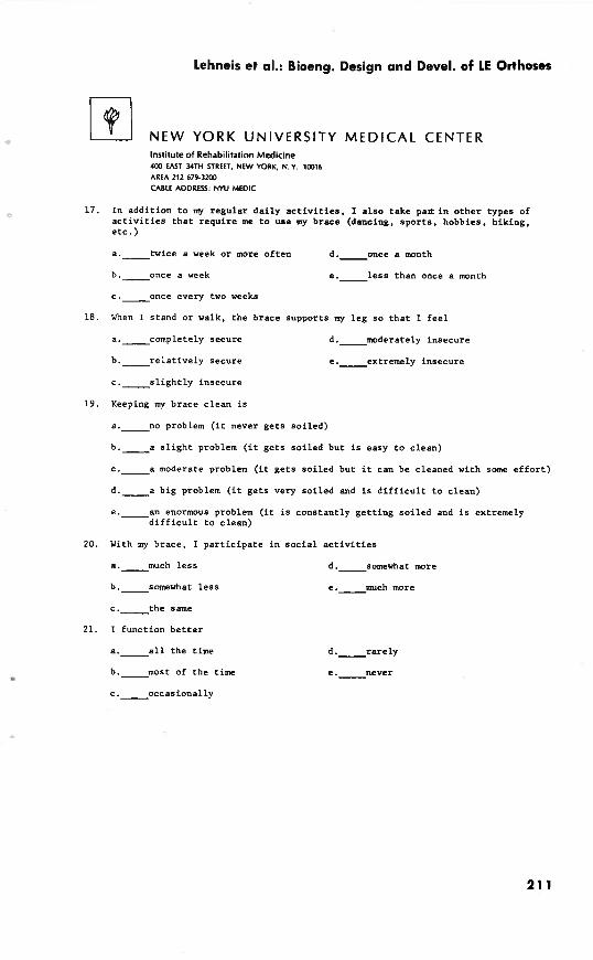
Lehneis et al.: Bioeng. Design and Devel. of LE Orthoses
N E W YORK UNIVERSITY MEDICAL CENTER Institute of Rehabilitation Medicine 403 EAST YTH STREET, N E W YORK. N.Y. 10016 AREA 212 679-3200
CABLE ADDRESS: N W M E D I C
17. In addi t ion t o my regular da i ly a c t i v i t i e s , I a l s o take p a l r i n o the r types of a c t i v i t i e s t h a t r equ i r e me t o use my brace (dancing, spo r t s , hobbies, h iking, e t c . )
a . t w i c e a week o r more o f t en d . o n c e a month
b . o n c e a week e . l e s s than once a month
c . o n c e every two weeks
18. When I stand o r walk, t he brace supports my l eg so t h a t I f e e l
a . c o m p l e t e l y secure d . m o d e r a t e l y insecure
b . r e l a t i v e l y secure
c . s l i g h t l y insecure
e . e x t r e m e l y insecure
19. Keeping my brace c lean i s
a . n o problem ( i t never ge t s so i l ed )
b . a s l i g h t problem ( i t g e t s soi led but i s easy t o c lean)
c . a moderate problem ( i t g e t s so i l ed but it can be cleaned with some e f f o r t )
d . a big problem ( i t ge t s very so i l ed and i s d i f f i c u l t t o c lean)
e . a n enormous problem ( i t i s constant ly ge t t i ng soi led and i s extremely d i f f i c u l t t o c lean)
20. With my brace, I p a r t i c i p a t e i n s o c i a l a c t i v i t i e s
a.-much l e s s
b . s o m e w h a t l e s s
c . t h e same
21. I funct ion b e t t e r
a . a l l the time
b . m o s t of the time
d . s o m e w h a t m r e
e.-much more
Bulletin of Prosthetics Research-Fall 1 973
N E W Y O R K U N I V E R S I T Y M E D I C A L CENTER lnrtituteof Rehabilitation Medicine ua EAST wrn STREET, NEW YORK, N. Y. ians AREA 212 679-3200
CABLE ADDRESS: NYU MEDIC
22. Has the brace made you f e e l better? (Please Explain)

Lehneis et al.: Bioeng. Design and Devel. of LE Orthoses
N E W YORK UNIVERSITY M E D I C A L CENTER Institute of Rehabilitation Medicine 4lX EAST 34TH STREET. NEW YORK, N. Y. 10216 AREA 212 619-3202 CABLE ADDRESS' NYU MEDIC
COMPARATIVE ORTHOTIC EVALUATION FORM - BK
Name Date
Prev ious b r a c e Length of t ime worn
P r e s e n t b r a c e Length of t ime worn
IN ANSWERING EACH QUESTION WHICH FOLLOWS, COMPARE YOUR PRESENT BRACE WITH THE BEST PREVIOUS BRACE. PLACE A CHECK MARK BY THE MOST CORRECT ANSWER.
1. The b r a c e i s g e n e r a l l y
a . m u c h more comfor tab le d . s o m e w h a t l e s s comfor tab le
b . s o m e w h a t more comfor tab le e . m u c h l e s s comfor tab le
c . a b o u t a s comfor tab le
2. The l e n g t h of t ime I am a b l e t o wear t h i s b race i s
a . m u c h s h o r t e r d . s o m e w h a t longer
b . s o m e w h a t s h o r t e r e . m u c h l o n g e r
c . a b o u t t h e same
3 . The problem of p e r s p i r a t i o n w i t h t h i s b r a c e i s
a . m u c h more s e v e r e d . s o m e w h a t l e s s s e v e r e
b . s o m e w h a t more s e v e r e e . m u c h l e s s s e v e r e
c . a b o u t t h e same
4. With t h i s b r a c e , s i t t i n g i s g e n e r a l l y
a . m u c h more c a f o r t a b l e d . s a e w h a t l e s s comfor tab le
b . s o m e w h a t more comfor tab le e . m u c h l e s s comfor tab le
c . a b o u t t h e same

Bulletin of Prosthetics Research-Fall 1973
N E W YORK UNIVERSITY M E D I C A L CENTER Institute of Rehabilitation Medicine 4CCl EAST 34TH STREET, NEW YORK, N. Y. 1(1(116 AREA 212 679-3200 CABLE ADDRESS: N W MEDIC
5. The weight of t h i s brace is
a . m u c h l i g h t e r d . s o m e w h a t heavier
b . s o m e w h a t l i g h t e r e . m u c h heavier
c . a b o u t the same
6 . The f i t of the brace i s
a . m u c h worse d . s o m e w h a t b e t t e r
b . s o m e w h a t worse e . g e n e r a l l y much b e t t e r
c . a b o u t the same
7 . In te r fe rence with c lo th ing from t h i s brace i s
a . m u c h l e s s frequent d . s o m e w h a t more frequent
b . s o m e w h a t l e s s frequent e . m u c h more frequent
c . a b o u t the same
8. My walking looks
a . m u c h b e t t e r d . s o m e w h a t worse
b . s o m e w h a t b e t t e r e . m u c h worse
c . a b o u t the same
9. I am ab le t o s tand and walk with t h i s brace f o r
a . m u c h s h o r t e r periods d . s o m e w h a t l o n g e r periods of time
b . s o m e w h a t s h o r t e r periods e . m u c h longer periods of time
c . a b o u t the same
10. My shoes wear
a.-much more evenly
b . s o m e w h a t more evenly
c . a b o u t the same
d . s z s - ; - h . a t l e s s evenly
e . m u c h l e s s evenly

Lehneis et al.: Bioeng. Design and Devel. of LE Orthoses
N E W Y O R K U N I V E R S I T Y M E D I C A L CENTER Institute of Rehabilitation Medicine 400 EAST 34TH STREET, NEW YORK. N. Y. 10016 AREA 212 679-3200
CABLE ADDRESS: NYU MEDIC
In te rchanging shoes i s
a . m u c h e a s i e r d.- somewhat more d i f f i c u l t
h . s o m e w h a t e a s i e r e . m u c h more d i f f i c u l t
c . a b o u t t h e same , - ,
12. The j a r o r shock when braced f o o t h i t s t h e f l o o r i s
a . m u c h l e s s d . s o m e w h a t g r e a t e r
b . s o m e w h a t l e s s e . m u c h g r e a t e r
c . a b o u t t h e same
13. Walking with t h i s b r a c e , I g e t t i r e d '
a . m u c h l e s s d . s o m e w h a t more
b.- somewhat l e s s e . m u c h more
c . a b o u t t h e same
14. Wearing t h i s b race , my l e g f e e l s
a.-much l e s s secure
b e p somewhat l e s s secure
c . a b o u t t h e same
15. This brace is g e n e r a l l y
d . s o m e w h a t more secure
e . m u c h more secure
a . m u c h b e t t e r f o r me than t h e d.- o t h e r brace
somewhat worse
b.- somewhat b e t t e r e . m u c h worse
c . a b o u t t h e same
16. With t h i s b r a c e , adjustments o r r e p a i r s were needed
a . m a n y more t imes
b . a few more t imes
c . a b o u t t h e same
d . l e s s f r e q u e n t l y
e . m u c h l e s s f r e q u e n t l y

Bulletin of Prosthetics Research-Fall 1973
NEW YORK UNIVERSITY MEDICAL CENTER Institute of Rehabilitation Medicine 4W EAST MTH STREET, NEW YORK, N. Y. l m 6 AREA 212 679-32W
CABLE ADDRESS: NYU MEDIC
17. The pain I had ( i f any) is
a . g o n e
b . m u c h l e s s
d . m u c h g rea t e r
e . s o m e w h a t g rea t e r
c . a b o u t t he same
18. As compared t o my old brace , I p a r t i c i p a t e i n s o c i a l a c t i v i t i e s
a . m u c h l e s s d . s o m e w h a t more
b . s o m e w h a t l e s s
c . a b o u t the same
19. I now funct ion b e t t e r
s . m u c h more
a . a l l the time d . r a r e l y
b . m o s t of the time e . n e v e r
c . o c c a s i o n a l l y
20. How has t h i s brace made you f e e l b e t t e r ? (Please Explain)
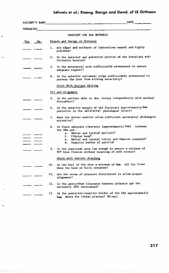
Lehneis et al.: Bioeng. Design and Devel. of LE Orthoses
PATIENT'S NAME DATE
THERAPIST
CHECKOUT FOR SKA ORTHOSIS
Yes No -- Finish and Design of Orthosis
-- 1. Are edges and surfaces of laminations smooth and highly polished?
-- 2. Is the anterior and posterior portion of the footplate suf- ficiently beveled?
-- 3. Is the metatarsal arch sufficiently pronounced to assure adequate support?
-- 4. Is the anterior calcaneal ridge sufficiently pronounced to prevent the foot from sliding anteriorly?
Check With Patient Sittins
Fit and Alignment
-- 5 . Is the patient able to don device independently with minimal discomfort?
-- 6. Is the anterior margin of the footplate approximately 6mm posterior to the metatarsal phalangeal joints?
-- 7. Does the dorsal section allow sufficient metatarsal phalangeal extens ion?
8. Is there adequate clearance (approximately 6mm) between the SKA and:
a. Medial and lateral malleoli? b. Fibular head? c. Medial and lateral tibial and femcral condyles? d. Superior border of patella?
-- 9. Is the popliteal area low enough to assure a minimum of 90° knee flexion without bunching of soft tissue?
Check with Patient Standing
-- 10. Is the heel of the shoe a minimum of 9 m off the floor when the knee is fully extended?
-- 11. Are the areas of pressure distributed to allow proper alignment?
-- 12. Is the prescribed clearance between orthosis and the extremity (#9) maintained?
-- 13. Is the posterior-superior border of the SKA approximately 6 m above the tibial plateau? (X-ray)

Bulletin of Prosthetics Research-Fall 1973
Yes No -- -- 14. Is the anterior-superior border of the SKA approximately
1 0 b above the mid-patella line.
-- 15. Is a lift indicated for the contralateral extremity?
-- 16. Is the patient comfortable?
Check with Patient Walking
-- 17. Are any valgus or varus deviations visible during stance?
-- 18. Is the knee stable at heel strike (only ball of foot touch- ing floor)?
-- 19. Is recurvatum sufficiently controlled?
-- 20. Is valgum or varum sufficiently controlled?
-- 21. Is there minimal piston action between the leg and,orthosis?
-- 22. Is the patient's performance in level walking satisfactory? Indicate b e l w the gait deviations that require attention.
Miscellaneous
-- 23. Is the color of the orthosis approximately the same as the limb?
-- 24. Does the patient consider the orthosis satisfactory as to com- fort, function, and appearance?
Patient Evaluation
-- 25. Is the patient's leg free from abrasions and discolorations immediately after the orthosis is removed?
26. Do the points of pressure appear to be distributed over the proper areas of the lower leg?
Conrments and Reconmendations

Lehneis et al.: Bioeng. Design and Devel. of LE Orthoses
SPIRAL BKO
LOOKS
Displeased Pleased I ! !
USEFULNESS
Not Useful Very Useful ! I !
COHPORT -- Uncomfortable Very Comfortable
! ! I
CONVENIENCE
Inconvenient Very Convenient ! I I
Rating Scale

Bulletin of Prosthetics Research-Fall 1973
CUiVWTIQIAL vs. SPIRAL BKO
LOOKS - More Pleasant
USEFULNESS
Get Around Less Get Around More ! ! !
COMFORT
More Uncomfortable More Comfort s5Ze ! ! !
C W W I E N C E
More Inconvenient More C0nvecLer.t ! ! I .
Rating Scale
Lehneis et al.: Bioeng. Design and Devel. of LE Orthoses
Appendix F
PUBLICATIONS
The following publications were,.produced during the course of the project. Frisina, W., B.E., and Lehrreis, H. R., C.P.O., Pressure mapping: A Preliminary Report. JOURNAL OF BIOMECHANICS, 3:526, 1970. Lehneis, H. R., C.P.O., Principles of Orthotics Alignment in the Lower Extremity. INSTRUCTIONAL COURSE LECTURES, AMERICAN ACADEMY OF ORTHO- PAEDIC SURGEONS, Vol. XX, pp. 131-136, 1971. Sarno, J. E., M.D., and Lehneis, H. R., C.P.O., Prescription Considerations for Plastic Below-Knee Orthoses. ARCHIVES OF PHYSICAL MEDICINE AND REHABILITA- TION, 52:11:503-510, 1971. Lehneis, H. R., C.P.O.; Frisina, W., B.E.; Marx, H. W., C.P.O.; and Goldfinger, G. H., R.P.T., PLASTIC SPIRAL BELOW-KNEE ORTHOSIS, New York University Medical Center, 33 pp, 1972. Lehneis, H. R., C.P.O., Ein spiralfoermiger Unterschenkelapparat aus Kunststoff. DIE ORTHOPAEDIETECHNISCHE VERSORGUNG DES FUSSES. George Thieme Verlag, Stuttgart, pp 81-85, 1972. Lehneis, H. R., C.P.O., New Developments in Lower Limb Orthotics Through Bioengineering. ARCHIVES OF PHYSICAL MEDICINE AND REHABILITATION. Scheduled to appear in 53:7:303-310, 1972.
SEMINAR
A Seminar entitled "New Concepts in Lower Extremity Orthotics" was conducted at the Institute of Rehabilitation Medicine, New York University Medical Center, April 28, 29, and 30, 1971 for the purpose of disseminating some of the research findings of this project.
AWARDS
Gold Medal, Scientific Exhibit, "Bioengineering Research Application in Lower Extremity Orthotics", Annual Meeting of the American Academy of Physical Medicine and Rehabilitation and the American Congress of Rehabilitation Medicine, New York, N.Y. Certificate of Merit, Scientific Exhibit, "Bioengineering Research Application in Lower Extremity Orthotics", Annual Meeting of the American Medical Association, Atlantic City, N.J.