Embed Size (px)
Citation preview


Bio-Inspired Fault-Tolerant Algorithms
for Network-on-Chip

Bio-Inspired Fault-Tolerant Algorithms
for Network-on-Chip
By
Muhammad Athar Javed Sethi

CRC PressTaylor & Francis Group52 Vanderbilt Avenue,New York, NY 10017
© 2020 by Taylor & Francis Group, LLC
CRC Press is an imprint of Taylor & Francis Group, an Informa business
No claim to original U.S. Government works
Printed on acid-free paper
International Standard Book Number-13: 9780367425906 (Hardback)
This book contains information obtained from authentic and highly regarded sources. Reasonable efforts have been made to publish reliable data and information, but the author and publisher cannot assume responsibility for the validity of all materials or the consequences of their use. The authors and publishers have attempted to trace the copyright holders of all material reproduced in this publication and apologize to copyright holders if permission to publish in this form has not been obtained. If any copyright material has not been acknowledged please write and let us know so we may rectify in any future reprint.
Except as permitted under U.S. Copyright Law, no part of this book may be reprinted, reproduced, transmitted, or utilized in any form by any electronic, mechanical, or other means, now known or hereafter invented, including photocopying, microfilming, and recording, or in any information storage or retrieval system, without written permission from the publishers.
For permission to photocopy or use material electronically from this work, please access www.copyright.com (www.copyright.com/) or contact the Copyright Clearance Center, Inc. (CCC), 222 Rosewood Drive, Danvers, MA 01923, 978–750–8400. CCC is a not-for-profit organization that provides licenses and registration for a variety of users. For organizations that have been granted a photocopy license by the CCC, a separate system of payment has been arranged.
Trademark Notice: Product or corporate names may be trademarks or registered trademarks, and are used only for identification and explanation without intent to infringe.
Library of Congress Cataloging‑in‑Publication DataA catalog record for this book has been requested
Visit the Taylor & Francis Web site at www.taylorandfrancis.com
and the CRC Press Web site at www.crcpress.com

Dedication
I dedicate this book to my wife, whose constant motivation, support and encouragement have helped me to write the book.

vii
ContentsPreface.......................................................................................................................xiAuthor Biography ................................................................................................... xiiiList of Abbreviations................................................................................................xvList of Symbols ......................................................................................................xvii
Chapter 1 Introduction ..........................................................................................1
1.1 Network on Chip .......................................................................11.2 Fault Tolerance ..........................................................................21.3 Why Use Bio-Inspired Algorithms for Fault Tolerance ............41.4 Objectives of Bio-Inspired Fault-Tolerant Algorithms ..............61.5 Book Contributions....................................................................61.6 Organization of the Book ..........................................................7
Chapter 2 In-Depth Review of Network on Chip .................................................9
2.1 Link-Sharing Mechanism ..........................................................92.2 NoC Fault-Tolerant Routing Algorithms ................................. 112.3 Switching Techniques .............................................................. 172.4 Buffer Management Techniques .............................................. 192.5 NoC Evaluation Parameters ....................................................202.6 NoC Clocking Mechanism ...................................................... 212.7 NoC Topologies .......................................................................242.8 Open Source ............................................................................252.9 NoC Connection Types ............................................................262.10 NoC Size ..................................................................................282.11 NoC Implementation Platforms ...............................................282.12 NoC Buffering Mechanisms ....................................................282.13 NoC PE–Router Interface ........................................................292.14 NoC Frequency and Technology ............................................. 322.15 NoC Area and Power Consumption ........................................ 332.16 NoC Router Ports and Bus Width............................................342.17 NoC Year of Proposal, Flit Size and Latency .........................342.18 Quality of Service ....................................................................36Summary ............................................................................................38
Chapter 3 Bio-Inspired Algorithms and Implementation ................................... 49
3.1 Swarm Intelligence Algorithms .............................................. 493.2 Ant Colony Optimization ........................................................ 493.3 Artificial Immune System ....................................................... 49
viii Contents
3.4 Firefly Algorithm ..................................................................... 493.5 Epidemic Spreading ................................................................ 493.6 Flower Pollination Algorithm ..................................................503.7 Artificial Bee Colony Algorithm .............................................503.8 Cat Swarm Optimization .........................................................503.9 Cuckoo Search .........................................................................503.10 Bat Algorithm .......................................................................... 513.11 Cuttlefish Algorithm ................................................................ 513.12 Harris Hawks Optimization .................................................... 513.13 Killer Whale Algorithm .......................................................... 513.14 Cobweb Network on Chip Topology ....................................... 513.15 Scalable Bio-Inspired Fault Detection Unit in Network
on Chip .................................................................................... 513.16 Autonomous Error Tolerant Architecture................................ 523.17 SpiNNaker Communication .................................................... 523.18 Autonomic Network on Chip Using the Biological
Immune System ....................................................................... 523.19 Fault-Tolerant NoC Using Biological Brain Techniques ......... 523.20 Bio-Inspired Online Fault Detection in the NoC
Interconnect ............................................................................. 523.21 Bio-Inspired Self-Aware NoC Fault-Tolerant Routing
Algorithm ................................................................................ 52
Chapter 4 Bio-Inspired NoC Fault-Tolerant Algorithms..................................... 55
4.1 Biological Brain Characteristics .............................................. 554.2 Synaptogenesis ........................................................................564.3 Sprouting ................................................................................. 574.4 Bio-Inspired NoC Algorithms ................................................. 574.5 Bio-Inspired NoC Framework ................................................. 594.6 Bio-Inspired NoC Network ..................................................... 594.7 Bio-Inspired NoC Fault-Tolerant Algorithm ........................... 624.8 Bio-Inspired BE and GT NoC Algorithm and
Architectures ........................................................................... 74Summary ............................................................................................88
Chapter 5 Analysis of Bio-Inspired NoC Fault-Tolerant Algorithms ................. 89
5.1 Research Framework, Design and Parameters ........................ 895.2 Bio-Inspired NoC Fault-Tolerant Algorithms
Analysis Results ...................................................................... 91Summary ..........................................................................................106

ixContents
Chapter 6 Conclusion and Future Work ............................................................ 109
6.1 Future Work ........................................................................... 110
Appendix A ........................................................................................................... 113
Appendix B ........................................................................................................... 185
Index ...................................................................................................................... 191

xi
PrefaceThe book is about bio-inspired fault-tolerant algorithms for network on chip (NoC). The inspiration for fault tolerance came from the biological brain, as it is highly robust and fault-tolerant itself. Synaptogenesis and sprouting are self-adapting and self-healing mechanisms of the brain being implemented in NoC. The results are quite promising, as these have made the NoC architecture fault-tolerant and reliable in terms of communication. To explain the bio-inspired algorithms efficiently, dif-ferent NoC architectural parameters are presented in the book. Moreover, different bio-inspired techniques are also presented in the book that represent how nature solves real-world problems.

xiii
Author BiographyDr. Muhammad Athar Javed Sethi is an assistant professor at the Department of Computer Systems Engineering, University of Engineering and Technology (UET), Peshawar, Pakistan. He received a Bachelor of Sciences in computer information systems engineering (honors) from UET Peshawar, Pakistan, in 2004. He received a Master of Sciences in computer systems engineering from the same university in 2008. He completed his PhD at Universiti Teknologi PETRONAS (UTP), Malaysia, in the Department of Electrical and Electronic Engineering in 2016. He was able to get different scholarships to pursue his studies. Dr. Sethi received the Institute of Electrical and Electronics Engineers (IEEE) award for the best student paper in 2013 and the most downloaded paper award from Elsevier in 2016 and 2017 for two dif-ferent papers. His research interests include network on chip (NoC), interconnection networks, computer architecture and embedded systems. Dr. Sethi has published numerous manuscripts in reputable journals, conferences and books. Currently, he is also actively involved in the technical program committees of various international conferences. He is serving as an associate editor for EAI Endorsed Transactions on Context-Aware Systems and Applications and at EAI Endorsed Transactions on Ambient Systems.

xv
List of AbbreviationsARQ Automatic Retransmission RequestASIC Application-Specific Integrated CircuitsBE Best EffortCRC Cyclic Redundancy CodesDN Direct NeighborDSP Digital Signal ProcessingFEC Forward Error CorrectionFPGA Field Programmable Gate ArraysGALS Globally Asynchronous Locally SynchronousGT Guaranteed ThroughputHPC High-Performance ComputingIN Immediate NeighborIP Internet ProtocolISE Information Set EastISN Information Set NorthISS Information Set SouthISW Information Set WestMPSoC Multiprocessor System on ChipNoC Network on ChipPE Processing ElementQoS Quality of ServiceSoC System on ChipSQL Structured Query LanguageTDM Time Division MultiplexingVC Virtual Channel

xvii
List of Symbolsbps bits per secondMBps megabyte per secondMW megawattµm micrometerµs microsecondsµW microwattmm2 millimeters squaredmW milliwattnm nanometerns nanosecondspj petajoulepj/packet petajoule per packetps picoseconds

1
1 Introduction
1.1 NETWORK on CHIP
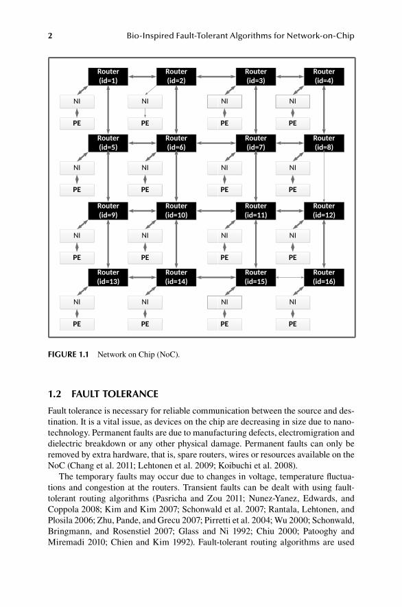
Network on Chip (NoC) is a communication standard for on-chip communication. NoC has replaced the crossbar interconnections and bus with a network of wires. Latency, congestion and delayed communication are the drawbacks of the bus. Due to the modular structure of the NoC, it can effectively reuse these resources. NoC also has other benefits of higher bandwidth, concurrency and scalability. The build-ing blocks of the NoC are routers, processing elements (PEs), network interfaces (NI) and interconnects. Routers are connected with each other and with the PE (local core). The NI separates data communications from network communications. The message generated by the PE is converted into packets by the NI and at the destina-tion; packets are again converted to messages by NI. The router receives the packets from NI and later routes the packets in the direction of the destination based on the rules of the routing algorithm (Benini and De Micheli 2002). Figure 1.1 shows a 4 × 4 mesh NoC with 16 routers and PEs. PEs can be homogeneous or heterogeneous resources. PEs can be a processor (P), memory (M), cache (C), reconfigurable block (re), digital signal processing (DSP) core or any other intellectual property cores, as shown in Figure 1.2.
In an NoC, regular and irregular are two major types of topologies through which PEs can be connected together. PEs and routers are connected in a systematic pat-tern in a regular topology. Moreover, an irregular topology has no systematic and structured pattern of PEs and routers. Figure 1.3 and Figure 1.4 show the NoC torus, tree, ring and irregular topologies.
The communication issues between multiple PEs are solved by NoC. However, as the number of devices is increasing on the chip, the NoC has encountered various communication issues in the form of faults. Devices are suffering from permanent and temporary faults due to the shrinking of device dimensions. Permanent faults can only be removed by redundant hardware, while transient faults can be overcome by routing algorithms. These routing algorithms are used to having reliable and effi-cient communication between multiple PEs by avoiding faulty routers and intercon-nects (Safaei and ValadBeigi 2012). In this research study, the focus is on recovering from temporary faults using fault-tolerant routing algorithms.
Fault tolerance is the basic concept, which separates the traditional data commu-nication network from the on-chip communication network. The Internet Protocol (IP) is one of the complex algorithms that provides fault tolerance in data networks using cyclic redundancy codes (CRC), forward error correction (FEC) and auto-matic retransmission request (ARQ). IP requires a lot of resources and area, which are unavailable in the on-chip network. Moreover, the low latency requirement is another characteristic of NoC, which is not guaranteed by the IP network (Bogdan, Dumitraş, and Marculescu 2007).
2 Bio-Inspired Fault-Tolerant Algorithms for Network-on-Chip
FIGURE 1.1 Network on Chip (NoC).
1.2 FAULT TOLERANCE
Fault tolerance is necessary for reliable communication between the source and des-tination. It is a vital issue, as devices on the chip are decreasing in size due to nano-technology. Permanent faults are due to manufacturing defects, electromigration and dielectric breakdown or any other physical damage. Permanent faults can only be removed by extra hardware, that is, spare routers, wires or resources available on the NoC (Chang et al. 2011; Lehtonen et al. 2009; Koibuchi et al. 2008).
The temporary faults may occur due to changes in voltage, temperature fluctua-tions and congestion at the routers. Transient faults can be dealt with using fault-tolerant routing algorithms (Pasricha and Zou 2011; Nunez-Yanez, Edwards, and Coppola 2008; Kim and Kim 2007; Schonwald et al. 2007; Rantala, Lehtonen, and Plosila 2006; Zhu, Pande, and Grecu 2007; Pirretti et al. 2004; Wu 2000; Schonwald, Bringmann, and Rosenstiel 2007; Glass and Ni 1992; Chiu 2000; Patooghy and Miremadi 2010; Chien and Kim 1992). Fault-tolerant routing algorithms are used

3Introduction
FIGURE 1.2 NoC with heterogeneous resources.
FIGURE 1.3 NoC torus and tree topologies.
to recover from the faulty interconnects in the NoC. These algorithms ensure reli-able and efficient communication between the source PE and destination PE. Deterministic, stochastic, fully adaptive and partial adaptive routing algorithms are the four broad categories used.

4 Bio-Inspired Fault-Tolerant Algorithms for Network-on-Chip
FIGURE 1.4 NoC ring and irregular topologies.
1.3 WHY USE BIO-INSPIRED ALGORITHMS FOR FAULT TOLERANCE
In deterministic routing, the packet routes from a certain point to another using a fixed path. These algorithms are simple to implement and deadlock-free; however, they are not fault-tolerant, lack adaptability and are not suitable for complex net-works. In stochastic routing algorithms, a packet is sent either in all directions or in a particular direction based on the type of routing algorithm. These algorithms are simple to implement, but they consume a great deal of bandwidth and are not fault-tolerant. In full adaptive routing algorithms, the routing depends on a table situated at the router. These algorithms are fault-tolerant, adaptive and very dynamic in nature, but updating the routing information takes a lot of time (latency), which affects the throughput of the NoC and consumes a lot of bandwidth. Finally, partial adaptive routing algorithms place restrictions on particular turns in the NoC. These algorithms solve the problem of deadlock and consume less bandwidth, as there are no routing tables. These algorithms are fault-tolerant and less complicated but lack the adaptability, end-to-end latency and interflit arrival time of the packets increases due to restrictions on particular turns in the NoC. Details of different fault-tolerant algorithms in the literature are described in Section 2.1 and summa-rized in Table 1.1.
The majority of the traditional fault-tolerant algorithms do not entirely address the faults in the NoC and have the drawbacks of high end-to-end latency and inter-\flit arrival time, low bandwidth utilization and less throughput. This makes the NoC communication unreliable, and the NoC architecture is not fault-tolerant. To overcome the drawbacks of deterministic, stochastic, fully adaptive and partially adaptive routing algorithms, novel biological inspired fault-tolerant algorithms were proposed. Bio-inspired algorithms can address the limitations of fault-tolerant algo-rithms by mimicking the fault-tolerant and robust mechanism of the brain based

5Introduction
TABLE 1.1NoC Literature on Fault-Tolerant AlgorithmsFault‑Tolerant Routing Algorithms
Categories Types Pros Cons
Deterministic routing 1. XY • Simple and easy to • Lacks adaptability.algorithms 2. YZ implement. • Not fault-tolerant.
3. XYZ • Deadlock-free. (HLAFT has better 4. ZYX routing choices and 5. Hybrid look-ahead fault tolerance due to
fault-tolerant routing look-ahead and local (HLAFT) along with routing mechanism.)random access buffer (RAB) deadlock recovery technique
Stochastic routing 1. Probabilistic gossip Simple and easy to • High power algorithms flooding scheme. implement. consumption.
2. Directed flooding • Congestion.scheme. • Deadlocks and
3. N-random walk. livelocks.4. Connection-oriented • Consumes a lot of
stochastic routing bandwidth.(COSR). • Not dynamic in nature.
• Not fault-tolerant.
Fully adaptive routing 1. Source routing for NoC • Dynamic in nature. • Continually updating algorithms (SRN). • Low-latency the routing table.
2. Force-directed communication. • Communication wormhole routing • Flits communication between routers.(FDWR). possible. • Routing table requires a
3. Fault-tolerant deflection • Fault-tolerant. lot of areas.routing (FTDR) and • Congestion at the hierarchical fault- router.tolerant deflection routing (FTDR-H).
4. Fault-tolerant-oASIS (FTO), the adaptive fault-tolerant routing algorithm.
5. Scalable fault-tolerant routing algorithm.
Partial adaptive routing 1. West first, negative • Less power • Lacks adaptability.algorithms first, north last, south consumption.
last. • No deadlock and 2. Odd-even. livelock.3. Planar adaptive. • No routing table.4. Hexagonal NoC partial • Fault-tolerant.
adaptive routing.

6 Bio-Inspired Fault-Tolerant Algorithms for Network-on-Chip
on the algorithms called “synaptogenesis” and “sprouting”. These bio-inspired NoC fault-tolerant algorithms have the following characteristics:
1. Bio-inspired algorithms do not pursue any fixed way toward a destination in contrast to a deterministic routing algorithm.
2. The proposed bio-inspired algorithms do not broadcast the packet (flits) in any direction that efficiently utilizes the bandwidth compared to stochastic routing algorithms.
3. There is no routing table in these bio-inspired algorithms, yet they are highly adaptive and robust compared to fully adaptive algorithms.
4. There is no constraint on turns in the NoC. However, it takes two nodes’ neighbor information before making a decision on the turn to take in con-trast to partial adaptive algorithms.
1.4 OBJECTIVES OF BIO-INSPIRED FAULT-TOLERANT ALGORITHMS
1. To develop the bio-inspired NoC fault-tolerant algorithm(s) to monitor the routers and interconnects between PEs (cores) to address the limitation in the literature on fault-tolerant algorithms. The bio-inspired fault-tolerant algorithms can:• Self-adapt (using synaptogenesis)• Self-heal (using sprouting)• Self-optimize (using best-effort and guaranteed throughput services)
2. To design the NoC architecture that adopt bio-inspired algorithm(s) to make the NoC architecture fault-tolerant and reliable.
1.5 BOOK CONTRIBUTIONS
1. Implementation of a fault-tolerant synaptogenesis algorithm using best-effort services. In this algorithm, packet switching was used to traverse the flits over the NoC. The fault was detected using credit-based flow control.
2. Implementation of a fault-tolerant sprouting algorithm using best-effort ser-vices. In this algorithm, packet switching was used to traverse the flits over NoC. The fault detection mechanism is improved by the sprouting. The fault was detected by the neighboring router when a flit was received on the blocked port.
3. Implementation of a bio-inspired fault-tolerant algorithm using the guaran-teed throughput approach. In this algorithm, a connection-oriented mecha-nism was used for traversing flits over the NoC. The fault was detected by the neighboring router as the flit was received on the blocked port. No flow control technique was required, as the flow was synchronized by a clock.
4. Implementation of a bio-inspired fault-tolerant algorithm using combined best-effort and guaranteed throughput services. In this algorithm, the con-nectionless and connection-oriented mechanisms of packet switching were combined. The fault was detected by a neighboring router as a flit was

7Introduction
received on the blocked port. For guaranteed throughput, no flow control technique was required, while the credit-based flow control technique was needed for the connectionless mechanism.
5. Review of the NoC architectures based on different parameters.
1.6 ORGANIZATION OF THE BOOK
Chapter 2 of this book provides a literature review on NoC fault-tolerant routing algorithms. Moreover, this chapter also explains the different parameters of the NoC used in the bio-inspired fault-tolerant algorithms.
Chapter 3 is about biologically inspired algorithms solving real-world problems. Moreover, this chapter also discusses the implementation of biological mechanisms in the NoC to address various issues. Bio-inspired fault-tolerant routing algorithms for NoC; bio-inspired NoC framework; bio-inspired NoC network; and bio-inspired NoC algorithms using BE, GT and combined BE-GT are described in Chapter 4.
Chapter 5 describes the experimental results. In this chapter, the bio-inspired algorithm, including the literature algorithms, are thoroughly analyzed and com-pared and different conclusions are derived.
The book is concluded in Chapter 6. In this chapter, the overall summary of the book is presented along with future recommendations. The specific details of sur-vey studies related to each of NoC architectures are provided in Appendix A, while Appendix B contains the actual fault detection code.
REFERENCES
Atienza, David, Federico Angiolini, Srinivasan Murali, Antonio Pullini, Luca Benini, and Giovanni De Micheli. 2008. “Network-on-chip design and synthesis outlook.” Integration 41 (3):340–359.
Benini, Luca, and Giovanni De Micheli. 2002. “Networks on chips: A new SoC paradigm.” Computer 35 (1):70–78.
Bogdan, Paul, Tudor Dumitraş, and Radu Marculescu. 2007. “Stochastic communication: A new paradigm for fault-tolerant networks-on-chip.” VLSI Design 2007.
Chang, Yung-Chang, Ching-Te Chiu, Shih-Yin Lin, and Chung-Kai Liu. 2011. “On the design and analysis of fault tolerant NoC architecture using spare routers.” Proceedings of the 16th Asia and South Pacific Design Automation Conference.
Chien, Andrew A, and Jae H Kim. 1992. Planar-adaptive routing: Low-cost adaptive networks for multiprocessors. Vol. 20: ACM.
Chiu, Ge-Ming. 2000. “The odd-even turn model for adaptive routing.” IEEE Transactions on Parallel and Distributed Systems 11 (7):729–738.
Glass, Christopher J, and Lionel M Ni. 1992. “The turn model for adaptive routing.” ACM SIGARCH Computer Architecture News 20 (2):278–287.
Guerrier, Pierre, and Alain Greiner. 2008. “A generic architecture for on-chip packet-switched interconnections.” Design, Automation, and Test in Europe.
Kim, Young Bok, and Yong-Bin Kim. 2007. “Fault tolerant source routing for network-on-chip.” 22nd IEEE International Symposium on Defect and Fault-Tolerance in VLSI Systems (DFT 2007).
Koibuchi, Michihiro, Hiroki Matsutani, Hideharu Amano, and Timothy Mark Pinkston. 2008. “A lightweight fault-tolerant mechanism for network-on-chip.” Proceedings of the Second ACM/IEEE International Symposium on Networks-on-Chip.

8 Bio-Inspired Fault-Tolerant Algorithms for Network-on-Chip
Lehtonen, Teijo, David Wolpert, Pasi Liljeberg, Juha Plosila, and Paul Ampadu. 2009. “Self-adaptive system for addressing permanent errors in on-chip interconnects.” IEEE Transactions on Very Large Scale Integration (VLSI) Systems 18 (4):527–540.
Nunez-Yanez, José L, Doug Edwards, and Antonio Marcello Coppola. 2008. “Adaptive rout-ing strategies for fault-tolerant on-chip networks in dynamically reconfigurable sys-tems.” IET Computers & Digital Techniques 2 (3):184–198.
Pasricha, Sudeep, and Yong Zou. 2011. “A low overhead fault tolerant routing scheme for 3D Networks-on-Chip.” 2011 12th International Symposium on Quality Electronic Design.
Patooghy, Ahmad, and Seyed Ghassem Miremadi. 2010. “Complement routing: A methodol-ogy to design reliable routing algorithm for network on chips.” Microprocessors and Microsystems 34 (6):163–173.
Pirretti, Matthew, Greg M Link, Richard R Brooks, Narayanan Vijaykrishnan, Mahmut Kandemir, and Mary Jane Irwin. 2004. “Fault tolerant algorithms for network-on-chip interconnect.” IEEE Computer Society Annual Symposium on VLSI.
Rantala, Ville, Teijo Lehtonen, and Juha Plosila. 2006. Network on chip routing algorithms: Citeseer.
Safaei, Farshad, and Majed ValadBeigi. 2012. “An efficient routing methodology to toler-ate static and dynamic faults in 2-D mesh networks-on-chip.” Microprocessors and Microsystems 36 (7):531–542.
Schonwald, Timo, Oliver Bringmann, and Wolfgang Rosenstiel. 2007. “Region-based routing algorithm for network-on-chip architectures.” Norchip 2007.
Schonwald, Timo, Jochen Zimmermann, Oliver Bringmann, and Wolfgang Rosenstiel. 2007. “Fully adaptive fault-tolerant routing algorithm for network-on-chip architectures.” 10th EUROMICRO Conference on Digital System Design Architectures, Methods and Tools (DSD 2007).
Seifi, Mohammad Reza, and Mohammad Eshghi. 2012. “Clustered NoC, a suitable design for group communications in Network on Chip.” Computers & Electrical Engineering 38 (1):82–95.
Wu, Jie. 2000. “A fault-tolerant adaptive and minimal routing approach in nD meshes.” Proceedings 2000 International Conference on Parallel Processing.
Zhu, Haibo, Partha Pratim Pande, and Cristian Grecu. 2007. “Performance evaluation of adaptive routing algorithms for achieving fault tolerance in NoC fabrics.” 2007 IEEE International Conf. on Application-specific Systems, Architectures and Processors (ASAP).

9
2 In-Depth Review of Network on Chip
2.1 LINK-SHARING MECHANISM
The link-sharing mechanism defines the way a communication channel is shared between multiple sources and destinations in the network on chip (NoC). Link-sharing mechanisms are divided into two broad categories: circuit switching and packet switching (connection-oriented and connectionless). According to the litera-ture, most of the NoC architectures use packet switching, whereas only a few use circuit switching. This clearly shows the interest in the effective and efficient utiliza-tion of resources compared to allocating the resources for particular time periods. In circuit switching–based connections, the resources can be underutilized at cer-tain times. Two NoC architectures use spatial division multiplexing (SDM)–based packet-switching techniques, while another uses wavelength division multiplexing (WDM) for link sharing.
The circuit-switching connections also lack the ability to react rapidly to specific changes in bandwidth and throughput requirements by processing elements (PEs) (Guerrier and Greiner 2008). To efficiently utilize the bandwidth of the NoC, the concept of virtual channels has been introduced using time division multiplexing (Moraes et al. 2004), frequency division multiplexing or a combination of both tech-niques (Ganguly et al. 2010). Despite the drawbacks of the circuit-switching tech-nique, it is still being used by NoC applications that require guaranteed services (Ogras, Hu, and Marculescu 2005). Future link-sharing mechanisms should include the adaptive and hybridized mechanisms, which can switch between circuit and packet switching based on the traffic load and PE requirements.
2.1.1 CirCuit SwitChing
In circuit switching, a physical link is established between the source and destination before data transmission. After the connection is established, flits (flow control dig-its) or packets traverse various routers. The connection is established until all pack-ets are received at the destination (Nurmi 2005). The circuit-switching technique is better for high-traffic, real-time applications. These applications generate and send traffic at a higher injection rate. As there is a separate link between the source and destination, there is no communication delay problem and high throughput can be achieved. In circuit switching, the bandwidth is reserved for the entire duration of data transmission, but resources (routers and links) are busy until all the data are received at the destination. The setup of the path from source to destination increases the unnecessary delay (Pande et al. 2005). NoC architectures which are based on circuit-switching techniques include (Lines 2004; Hilton and Nelson 2006; Chang,

10 Bio-Inspired Fault-Tolerant Algorithms for Network-on-Chip
Shen, and Chen 2006; Dally and Towles 2001; Henriksson, Wiklund, and Liu 2003; Peña-Ramos and Parra-Michel 2011; Wiklund and Liu 2003; Wolkotte et al. 2005; Butts 2007; Ainsworth and Pinkston 2007; Braun et al. 2007). The Dally et al. (Dally and Towles 2001) NoC architecture provides virtual channel–based circuit switch-ing while OCN (Henriksson, Wiklund, and Liu 2003) provides circuit switching using round-robin arbitration. The only drawback of the techniques that adopt circuit switching is the average utilization of the link. The links are underutilized at certain times. Therefore, to address these issues, packet switching must also be used in these systems to efficiently utilize the communication channel (Rijpkema et al. 2003).
2.1.2 PaCket SwitChing
In packet switching, routers decide in which direction of the NoC a packet should be sent based on the routing algorithm. In packet switching, the messages generated by the source are divided into packets and flits. The reason for dividing the messages into packets and flits is to utilize the bandwidth of the NoC efficiently. The flits can traverse the multiple paths available on the NoC (Wang et al. 2011). Several NoC architectures are based on packet switching: (Guerrier and Greiner 2008; Moraes et al. 2004; Lines 2004; Bolotin et al. 2004; Wang, Ahonen, and Nurmi 2007; Bainbridge and Furber 2002; Siguenza-Tortosa and Nurmi 2002; Kumar et al. 2002; Taylor et al. 2002; Zeferino and Susin 2003; Samuelsson and Kumar 2004; Zeferino, Kreutz, and Susin 2004; Chan and Parameswaran 2004; Bartic et al. 2005; Neeb and Wehn 2008; Kariniemi and Nurmi 2006; Mullins, West, and Moore 2006; Zid et al. 2006; Bell et al. 2008; Hoffman et al. 2007; Janarthanan, Swaminathan, and Tomko 2007; Hosseinabady et al. 2007; Soteriou et al. 2006; Kumar et al. 2008; Samman, Hollstein, and Glesner 2009; Feero and Pande 2008; Lan et al. 2011; Krasteva, De la Torre, and Riesgo 2010; Wu, Tang, and Hsu 2011; Mishra, Nidhi, and Kishore 2012; Shu et al. 2012; Choudhary and Qureshi 2012; Arteris 2005; Coppola et al. 2004; Feliciian and Furber 2004; Beigné et al. 2005; Panades, Greiner, and Sheibanyrad 2006; Schuck, Lamparth, and Becker 2007; Beigné et al. 2009; Forsell 2002; Ching, Schaumont, and Verbauwhede 2004; Hu and Marculescu 2004; Anjo et al. 2004; Lee, Lee, and Lee 2004; Bobda et al. 2005; Sanusi and Wang 2006; Pionteck, Koch, and Albrecht 2006; Ogras et al. 2006; Palermo et al. 2007; Lattard et al. 2008; Wang et al. 2010; Lee et al. 2012; Kao and Chao 2012; Yang et al. 2014; Al Faruque, Ebi, and Henkel 2010). These packet-switching NoC architectures either use round-robin arbitration, virtual channels or any other mechanisms, and specific details can be found in Appendix A. Figure 2.1 shows that multiple parallel virtual channels are created between various source PEs and destination PEs through a connection-ori-ented mechanism.
SDM and WDM are the link-sharing techniques used by some NoC architec-tures. SDM physically divides every link and buffer into multiple virtual circuits. Every virtual circuit is assigned a portion of the bandwidth. SDM uses wormhole switching for flow control (Song and Edwards 2011). An architecture and compiler for aSoC (Liang et al. 2004) and SDM NoC (Leroy et al. 2005) are two examples of SDM. WDM can send multiple signals simultaneously to attain higher throughput. The wavelength determines the destination address in WDM or routing. This makes

11In-Depth Review of Network on Chip
the WDM the contention-free link-sharing mechanism. The ORNoC (Le Beux et al. 2011), NoC architecture provides link sharing using WDM. Some of the architec-tures have not provided any information regarding their link-sharing mechanism. The details of the architectures are provided in Appendix A.
2.2 noC FAULT-TOLERANT ROUTING ALGORITHMS
The routing algorithm defines the path for a packet between the source PE and des-tination PE. Fault-tolerant algorithms are used to recover from a faulty interconnect in the NoC by ensuring reliable and efficient communication between the source PE and destination PE. There are basically four broad categories of routing algorithms. They are deterministic, stochastic, fully adaptive and partial adaptive routing algo-rithms. When the routing decision is made by the source, it is called source routing, whereas if the immediate nodes of the NoC make the decision, then the routing algorithm is categorized as distributed routing (Moraes et al. 2004).
Deterministic routing algorithms deliver an orderly packet and require fewer resources compared to adaptive routing algorithms. Adaptive routing algorithms pro-vide better throughput and low latency by having alternative paths due to congested or faulty routes. Deterministic and partially adaptive algorithms are deadlock and livelock free, whereas fully adaptive algorithms require some precaution by having deadlock-, livelock- and congestion-avoiding techniques (Ogras, Hu, and Marculescu
FIGURE 2.1 Multiple virtual channels (some PEs and network interfaces [NIs] are removed for clarity).
12 Bio-Inspired Fault-Tolerant Algorithms for Network-on-Chip
2005). Adaptive routing algorithms need specialized modules at the receiver to reor-der the packets, which in turn increases the design complexity and latency of the packets. Deterministic routing algorithms perform well under uniform traffic pat-terns, while adaptive routing algorithms are preferred for bursty and irregular traffic (Palesi and Daneshtalab 2014). A small number of NoC architectures have not speci-fied nor is it clear which routing algorithm they are using. In the literature, determin-istic routing algorithms have been used because they are less complex to implement.
2.2.1 DeterminiStiC routing algorithmS
In deterministic routing the packet routes from a certain point to another using a fixed path. These algorithms lack adaptivity, and they are not fault-tolerant. XY, YX, XYZ and ZYX (Pasricha and Zou 2011; Kim and Kim 2007; Schonwald et al. 2007; Zhu, Pande, and Grecu 2007; Schonwald, Bringmann, and Rosenstiel 2007; Glass and Ni 1992; Chiu 2000) are a few examples of dimension order routing (DOR) algo-rithms. DOR algorithms are the simplest deterministic routing algorithms, and they are deadlock-free. In minimal path routing, the packet can traverse using multiple (shortest) paths to reach the destination. Minimum path routing algorithms are prone to deadlocks compared to DOR (Bahrebar and Stroobandt 2014).
In the XY routing algorithm, the packet is first reached at the row of the destina-tion node and then to the column of the destination node. In YX, the packet is first routed to the column of the destination node and then to the row. These algorithms are static, deadlock-free and deterministic. They lack adaptivity and are not suitable for sophisticated network resources. ZYX is the 3D NoC routing algorithm, and in this algorithm, the packet is first sent to the NoC layer, then it is routed to the column of the destination and later it is sent to the particular row of the destination (Pasricha and Zou 2011). The ZYX algorithm is static, deterministic and deadlock-free, but it lacks adaptivity. Hybrid look-ahead fault-tolerant routing (HLAFT) is a determinis-tic routing algorithm as it utilizes both local and look-ahead routing to ensure fault tolerance in the NoC. HLAFT also uses a random access buffer (RAB) mechanism to avoid deadlock in the NoC. HLAFTs have lower latency and higher throughput compared to DOR (Ahmed and Abdallah 2014).
NoC architectures that have deterministic routing are (Moraes et al. 2004; Liang, Swaminathan, and Tessier 2000; Karim, Nguyen, and Dey 2002; Lines 2004; Bolotin et al. 2004; Leroy et al. 2005; Hilton and Nelson 2006; Chang, Shen, and Chen 2006; Salminen et al. 2006; Castells-Rufas, Joven, and Carrabina 2006; Janarthanan and Tomko 2008; Dally and Towles 2001; Kumar et al. 2002; Henriksson, Wiklund, and Liu 2003; Zeferino and Susin 2003; Bertozzi and Benini 2004; Zeferino, Kreutz, and Susin 2004; Bartic et al. 2005; Kariniemi and Nurmi 2006; Bell et al. 2008; Gratz et al. 2007; Hoffman et al. 2007; Janarthanan, Swaminathan, and Tomko 2007; Soteriou et al. 2006; Kumar et al. 2008; Samman, Hollstein, and Glesner 2009; Lan et al. 2011; Krasteva, De la Torre, and Riesgo 2010; Peña-Ramos and Parra-Michel 2011; Shu et al. 2012; Al Faruque, Ebi, and Henkel 2010; Choudhary and Qureshi 2012; Evain, Diguet, and Houzet 2004; Coppola et al. 2004; Bjerregaard and Sparso 2004, 2005a, 2005c; Beigné et al. 2005; Panades, Greiner, and Sheibanyrad 2006; Schuck, Lamparth, and Becker 2007; Wang and Bagherzadeh 2014; Heisswolf et al.

13In-Depth Review of Network on Chip
2015; Forsell 2002; Hu and Marculescu 2004; Chi and Chen 2004; Bobda et al. 2005; Sanusi and Wang 2006; Pionteck, Koch, and Albrecht 2006; Wang et al. 2010; Bahirat and Pasricha 2014; DiTomaso, Kodi, and Louri 2014; Poluri and Louri 2014).
2.2.2 StoChaStiC routing algorithmS
Packets are broadcast in either all directions or a particular direction of the NoC depending on the type of algorithm. These algorithms are simple to implement, but they consume a lot of power. They have congestion, deadlock, livelock and high-bandwidth utilization problems. These algorithms do not perform well even at low traffic rates because they broadcast the packet in all directions. These algorithms are not fault-tolerant, lack adaptivity and are not dynamic in nature. A few examples of stochastic algorithms are probabilistic gossip flooding scheme, directed flooding, N-random walk (Pasricha and Zou 2011; Zhu, Pande, and Grecu 2007; Pirretti et al. 2004; Patooghy and Miremadi 2010) and connection-oriented stochastic routing (COSR) (Nunez-Yanez, Edwards, and Coppola 2008). None of the NoC architectures has used the stochastic routing algorithm due to its drawbacks.
2.2.2.1 Probabilistic Gossip Flooding SchemeIn this algorithm, packets are sent multiple times to multiple paths of the NoC. These algorithms do not have any information about the destination. When one of the copies of the packet arrives at the destination, all other packet copies are deleted. This algorithm consumes a lot of bandwidth and power, lacks adaptivity and is not dynamic in nature. Also, the packets in this scheme may get lost or collapse during the traversal of the NoC (Zhu, Pande, and Grecu 2007; Pirretti et al. 2004).
2.2.2.2 Directed Flooding SchemePackets are replicated in particular or directed paths in the directed flooding scheme. In terms of performance, this algorithm is better than the probabilistic algorithm, as it consumes a small amount of bandwidth and few network resources (Pasricha and Zou 2011). This algorithm is less influenced by higher error rates. The performance is better than probabilistic algorithms when the gossip rate is low (Kim and Kim 2007).
2.2.2.3 N-random Walk(N) number of packets are sent to the network in a particular direction in the N-random walk algorithm. This algorithm is efficient compared to directed flood-ing, as it consumes a small amount of bandwidth and power (Zhu, Pande, and Grecu 2007). The random walk has less communication overhead compared to the flood-ing scheme, and it also provides a useful level of fault tolerance (Bjerregaard and Mahadevan 2006).
2.2.2.4 Connection-Oriented Stochastic RoutingThis scheme is a hybrid algorithm that combines circuit and packet switching. A con-nection is established using circuit switching between the source and destination. After a connection is established, packets are sent over the established connection

14 Bio-Inspired Fault-Tolerant Algorithms for Network-on-Chip
using packet switching (Nunez-Yanez, Edwards, and Coppola 2008). This algorithm is easy to implement and is fault-tolerant. The drawback of this algorithm is that the connection established for a certain period of time may lead to underutilization of the bandwidth, congestion and denial of services to some PEs.
2.2.3 Fully aDaPtive routing algorithmS
The routing of fully adaptive algorithms depends upon the routing table or on the routing information collected from the neighbor nodes at the router. Based on this information, the direction of the packet is decided at run time. Routers constantly communicate with each other to update the routing table or neighbor node informa-tion. The updating of routing information takes a lot of power and time, consequently affecting the throughput of the NoC (Pasricha and Zou 2011; Rantala, Lehtonen, and Plosila 2006). Source routing for NoC (SRN) and force-directed wormhole routing (FDWR) are two examples of fully adaptive routing algorithms (Kim and Kim 2007; Schonwald et al. 2007). Fully adaptive routing algorithms are fault-tolerant and very dynamic, but the updating of routing information consumes a lot of area and power, which sometimes degrade the performance of the NoC. The flow of control packets between routers at times creates congestion and deadlock situations in the NoC. The routing algorithms are fully adaptive, but they do not have a routing table. They col-lect the neighbor’s information through certain control packets. Based on this infor-mation, the router decides in which direction the packet should be routed.
A few NoC architectures using source-based routing are (Guerrier and Greiner 2008; Rijpkema et al. 2003; Paukovits and Kopetz 2008; Hansson, Subburaman, and Goossens 2009; Bainbridge and Furber 2002; Siguenza-Tortosa and Nurmi 2002; Pande et al. 2003; Kim et al. 2005; Kariniemi and Nurmi 2006; Zid et al. 2006; Vangal et al. 2008; Hosseinabady et al. 2007; Soteriou et al. 2006; El-Moursy, Korzec, and Ismail 2009; Krasteva, De la Torre, and Riesgo 2010; Yaghini, Eghbal, and Bagherzadeh 2015; Bjerregaard and Sparso 2004, 2005a, 2005c; Kavaldjiev, Smit, Jansen et al. 2006; Mondinelli, Borgatti, and KOVACS VAJNA 2004; Lee et al. 2005; Bouhraoua and Elrabaa 2006; Ahmad, Erdogan, and Khawam 2006).
2.2.3.1 Source Routing for NoCRouter discovery and route maintenance are two main components of this algorithm. First, the algorithm dynamically discovers its path from the source to destination. Later, it maintains the path by adapting another new path from the source to bypass the faulty router. Due to a limited number of broadcasts, SRN has less communica-tion overhead and is not able to handle complex networks. It has a restriction on its source routing table, which limits its adaptivity (Kim and Kim 2007).
2.2.3.2 Force-Directed Wormhole RoutingFDWR divides the traffic over the network by force. It follows the wormhole-switch-ing mechanism. In wormhole switching, the packet is divided into header, body and tail flits. The header flit finds and contains the path until the destination. The body and tail flit follow the header flit’s specified path. Body flits contain the data to be transferred from the source to destination, while tail flits inform the routers and the

15In-Depth Review of Network on Chip
destination about the termination of communication. In FDWR, the header flit finds the path by avoiding the faulty routers. The neighbor routers, which are working cor-rectly, exchange messages about their availability and working status. If the routers receive the messages with the help of a routing table, FDWR finds the shortest path from the source to destination (Schonwald et al. 2007). The advantage of FDWR is that it evenly distributes the traffic across the network with the help of a routing table. It is fault-tolerant, as it avoids the faulty routers by taking another path. In this algorithm, the flits of the packets may choose different ways on the NoC. With the help of a sequence number, flits and packets are reordered at the destination. The drawback of this algorithm is that the destination has to reorder a packet, which consumes power and time.
Fault-tolerant deflection routing (FTDR) and the hierarchical-routing-table-based FTDR algorithm (FTDR-H) detects transients and permanent faults for bufferless NoCs across links. FTDR and FTDR-H results are better than stochastic routing algorithms. The drawback of these techniques is that when a fault is detected, the link is shut down in a bidirectional way, and transient faults are only valid for one cycle (Feng et al. 2012). Fault-tolerant-OASIS (FTO) detects and works around tran-sient, intermittent and permanent faults in the NoC. FTO ensures fault tolerance in the NoC by using the least amount of additional hardware complexity. FTO performs better than DOR (Ahmed and Abdallah 2016). The scalable fault-tolerant routing algorithm detects permanent failures in the NoC links and reconfigures the rout-ing path using active routers and links. The drawback of the routing algorithm is its complexity, but it provides multiple routing paths in case of faults (Kia et al. 2015).
The advantages of the fully adaptive routing algorithms are that they are dynamic in nature. The router decides at run time to which link it should route the packet. However, continually updating the routing table requires a lot of time, area and power. Communication between routers in a fully adaptive routing algorithm cre-ates deadlock and congestion in the NoC (Pasricha and Zou 2011; Patooghy and Miremadi 2010).
2.2.4 Partial aDaPtive routing algorithmS
Partial adaptive algorithms, as the name implies, are partially adaptive. They put some restrictions on the routes that can be taken by a router in the NoC (Moraes et al. 2004). These algorithms solve the problem of deadlock and consume less power, as there are no routing tables. These algorithms are fault-tolerant but limit the adaptiv-ity of the NoC and the latency of the packets increases due to restrictions on turns (Pasricha and Zou 2011). West first, negative first, north last, south last, odd-even and planar adaptive (Pasricha and Zou 2011; Rantala, Lehtonen, and Plosila 2006; Zhu, Pande, and Grecu 2007; Wu 2000; Schonwald, Bringmann, and Rosenstiel 2007; Glass and Ni 1992; Chiu 2000; Chien and Kim 1992) are a few examples of these algorithms.
These NoC architectures (Janarthanan, Swaminathan, and Tomko 2007; Wu, Tang, and Hsu 2011; Yang et al. 2014; Choudhary and Qureshi 2012; Postman et al. 2012; Schuck, Lamparth, and Becker 2007) have turn-based adaptive routing algo-rithms. Odd-even routing algorithms are used by these (Taylor et al. 2002; Chan and

16 Bio-Inspired Fault-Tolerant Algorithms for Network-on-Chip
Parameswaran 2004; Hoffman et al. 2007; Samman, Hollstein, and Glesner 2009; Lan et al. 2011; Choudhary and Qureshi 2012; Evain, Diguet, and Houzet 2004; Beigné et al. 2005; Hu and Marculescu 2004; Lattard et al. 2008) NoC architectures. A few of the NoC architectures that have distributed routing algorithms are (Stefan, Molnos, and Goossens 2012; Samuelsson and Kumar 2004; Wiklund and Liu 2003; Wolkotte et al. 2005; Schoeberl 2007), while Nostrum (Penolazzi and Jantsch 2006; Millberg et al. 2004) has TDM-based deflective routing. Other NoC architectures follow stream-based routing, e-cube routing, Dijsktra shortest path routing, shortest distance, shortest path first and temperature first routing algorithms. The details of these and other NoC architectures are presented in Appendix A.
2.2.4.1 West First, Negative First, North Last and South Last Routing Algorithms
In the west first algorithm, packets transmitted to the west should be first because later in this algorithm, the packet cannot be sent in a westerly direction. Similarly, the negative first algorithm allows all other turns except turns from a positive direc-tion to the negative direction. Packet routing in the negative direction must be done first, and all other turns in the NoC later. In the north last algorithm, packets that need to be routed north must be transferred last. However, in the south last algorithm, packets can be routed in a southerly direction as the last turn (Rantala, Lehtonen, and Plosila 2006).
2.2.4.2 Odd-Even Routing AlgorithmIn the odd-even routing algorithm, no deadlock occurs. This algorithm imposes a restriction that at the even column, there should be no turns from east to north and from east to south. Similarly, in odd columns, there should be no turn from north to west and south to west. The advantage of this algorithm is that it avoids livelocks and consumes less power due to the restrictions on turns (Rantala, Lehtonen, and Plosila 2006; Chiu 2000).
One of the advantages of turn-based models is that no routing table is required. The router has to determine according to which turn algorithm it is routing the pack-ets. Routers can send the packet in the wrong direction. In turn-based algorithms, routers become more complex. Among all partial adaptive routing algorithms, the odd-even routing algorithm provides more adaptivity, as there are fewer restricted turns.
2.2.4.3 Planar Adaptive Routing AlgorithmThe essential requirement of a planar adaptive routing algorithm is that it has a con-stant number of virtual channels, and it does not depend on the size and dimen-sion of the network (Wu 2000). This algorithm routes the packet in two dimensions until it reaches the destination. The algorithm avoids deadlock while also consum-ing less routing time because there is no routing table. The planar adaptive algo-rithm can be applied to (n) dimensional planes by allocating three virtual channels (Chien and Kim 1992). The disadvantage of this algorithm is that it requires extra virtual channels for communication. The hexagonal NoC partial adaptive routing algorithm (Moriam and Fettweis 2016) uses a turn model for routing, and it avoids

17In-Depth Review of Network on Chip
the use of virtual channels. The algorithm is deadlock and livelock free, but does have increased complexity.
2.2.5 noC Fault-tolerant arChiteCtureS
The trends in using routing algorithms show that most of NoC architectures have used deterministic routing algorithms, while few NoC architectures are using fully and partial adaptive routing algorithms. However, none of the NoC architectures have used the stochastic routing algorithm. Less complex algorithms have been implemented, so that area and power consumption is less.
Dally et al. (Dally and Towles 2001) cover the transient faults that may occur due to errors in the packets. The transient faults can be recovered by checksum codes in the packet. PROTEO (Siguenza-Tortosa and Nurmi 2002) and Nexus (Lines 2004) claimed to be fault-tolerant, but no information is provided in the literature regarding it. Xpipes (Bertozzi and Benini 2004) also detects transient faults using distributed error detection bits. XGFT (Kariniemi and Nurmi 2006) detects the static, dynamic and transient faults using a fault diagnosis and repair (FDAR) algorithm. Other NoC architectures did not provide any information regarding fault tolerance in their archi-tecture. Specific details can be found in Appendix A.
2.3 SWITCHING TECHNIQUES
The term “switching technique” refers to the control of messages (packets or flits) flowing between routers in the NoC. It helps the routing algorithm avoid congestion and conflicts between routers. Circuit-switching techniques do not require a for-warding strategy, as the resources are already reserved for them. Packet switching requires a forwarding strategy, as it has to decide on a per-node basis and it requires buffering. In packet switching, flits are saved in the router before any routing deci-sion. There are broadly three types of switching techniques: store and forward, vir-tual cut-through and wormhole switching.
The buffering requirement of the virtual cut-through and store and forward tech-niques are one packet compared to a few flits in wormhole switching. The design complexity of virtual cut-through is high compared to the wormhole switching and store and forward technique. The cost (power consumption and area) of wormhole switching is lower compared to the virtual cut-through and store and forward tech-nique (Tatas et al. 2014). At low traffic rates, virtual cut-through has the same low latency as wormhole switching, whereas at high traffic loads, the virtual cut-through has a high throughput similar to the store and forward technique (Bartic et al. 2005). It is a trade-off between buffering, design complexity and cost when using these switching techniques.
2.3.1 Store anD ForwarD
In store and forward, the packet is completely received at the router and then a rout-ing decision is made on it. The drawback of this technique is more storage require-ments at the router. The latency of the packet also increases, as complete packets

18 Bio-Inspired Fault-Tolerant Algorithms for Network-on-Chip
are stored before routing (Rantala, Lehtonen, and Plosila 2006). Few of the NoC architectures (Castells-Rufas, Joven, and Carrabina 2006; Samuelsson and Kumar 2004; Forsell 2002; Mondinelli, Borgatti, and KOVACS VAJNA 2004; Anjo et al. 2004) use store and forward flow control techniques.
2.3.2 virtual Cut-through
In virtual cut-through flow control, the flit is sent to the next router when the neigh-bor router guarantees that the complete packet can be saved. If there is no space in the neighbor router, then the entire packet will be kept in that particular router. Virtual cut-through routers also need buffers to save the whole packet, but they have less latency compared to the store and forward technique (Rantala, Lehtonen, and Plosila 2006; Moraes et al. 2004; Tatas et al. 2014). When no packets are blocked in the buffers, then virtual cut-through switching achieves the same latency as worm-hole switching in NoC (Tatas et al. 2014). NoC architectures that have virtual cut-through as a flow control technique are (Castells-Rufas, Joven, and Carrabina 2006; Janarthanan and Tomko 2008; Bartic et al. 2005; Janarthanan, Swaminathan, and Tomko 2007; Grot et al. 2011; Mishra, Nidhi, and Kishore 2012; Lee et al. 2003; Pionteck, Koch, and Albrecht 2006; Qouneh et al. 2012).
2.3.3 wormhole SwitChing
In the wormhole-switching technique, a packet is divided into smaller pieces called flits (flow control digits). There are three types of flits; header, body and tail. The header flit finds and contains the routing information, whereas the body flit includes the data information. The body flits carry these flits from source to destination. The tail flit informs the routers about communication termination. The tail flit is received at the destination, which tells it about communication completion from a particular source. Wormhole switching has the least buffering requirement compared to the other two flow control techniques, as the router sends the flit to neighbor routers even if it has a space for a single flit. Wormhole switching has the least latency of packets compared to other techniques, as flits may follow multiple paths on the NoC (Rantala, Lehtonen, and Plosila 2006; Rijpkema et al. 2003). In some instances, the routing and control information is also provided in the packet by allocating a few control bits (Bertozzi and Benini 2004). The drawback of this technique is that when the header flit is blocked in any router, all the subsequent flits of a packet in mul-tiple routers are also blocked. This leads to a deadlock situation in the NoC (Tatas et al. 2014). Few architectures have separate control lines, and others use the flow of tokens for flow control between routers (Benini and De Micheli 2002; Kao and Chao 2012).
NoC architectures that have adopted wormhole switching as a flow control tech-nique are (Guerrier and Greiner 2008; Moraes et al. 2004; Rijpkema et al. 2003; Karim, Nguyen, and Dey 2002; Bolotin et al. 2004; Castells-Rufas, Joven, and Carrabina 2006; Wang, Ahonen, and Nurmi 2007; Dally and Towles 2001; Kumar et al. 2002; Taylor et al. 2002; Pande et al. 2003; Zeferino and Susin 2003; Bertozzi and Benini 2004; Zeferino, Kreutz, and Susin 2004; Chan and Parameswaran 2004; Kim et al. 2005; Neeb and Wehn 2008; Mullins, West, and Moore 2006; Zid et al.

19In-Depth Review of Network on Chip
2006; Bell et al. 2008; Gratz et al. 2007; Vangal et al. 2008; Hoffman et al. 2007; Hosseinabady et al. 2007; Soteriou et al. 2006; El-Moursy, Korzec, and Ismail 2009; Samman, Hollstein, and Glesner 2009; Feero and Pande 2008; Lan et al. 2011; Krasteva, De la Torre, and Riesgo 2010; Wu, Tang, and Hsu 2011; Shu et al. 2012; Yang et al. 2014; Al Faruque, Ebi, and Henkel 2010; Choudhary and Qureshi 2012; Arteris 2005; Yaghini, Eghbal, and Bagherzadeh 2015; Coppola et al. 2004; Feliciian and Furber 2004; Beigné et al. 2005; Panades, Greiner, and Sheibanyrad 2006; Schuck, Lamparth, and Becker 2007; Wang and Bagherzadeh 2014; Heisswolf et al. 2015; Ching, Schaumont, and Verbauwhede 2004; Hu and Marculescu 2004; Bouhraoua and Elrabaa 2006; Lee et al. 2006; Ahmad, Erdogan, and Khawam 2006; Ogras et al. 2006; Ainsworth and Pinkston 2007; Lattard et al. 2008; Lee et al. 2012).
Wolkotte et al. (Wolkotte et al. 2005) has separate control lines for an end-to-end flow control, while some architectures use the flow of tokens for flow control between routers (Postman et al. 2012; Wolkotte et al. 2005). The SWIFT (Postman et al. 2012) NoC architecture has token-based flow control.
2.4 BUFFER MANAGEMENT TECHNIQUES
Buffer management techniques are an important component in NoC to have reliable communication between sources and destinations. These techniques help to avoid buffer overflow, packet drop and congestion between routers. NoC architectures use credit-based and shared virtual channel control techniques. At times both these tech-niques can be used together for controlling access to the shared link. Due to less communication overhead in the shared virtual channel control technique, shared virtual channel control consumes less area and less power compared to the credit-based method (Bjerregaard and Sparsø 2005b).
2.4.1 CreDit-BaSeD teChnique
In this technique, the flow of flits between routers and PEs is managed by incre-menting and decrementing a credit counter. When a port sends a flit, it decrements the credit counter. This specifies that the output port is busy, as it just sends the flit. When the adjacent router receives the flit, it sends back the credit packet to the router so that it increases the credit counter. When the credit counter of the port reaches zero, it cannot send more flits at the particular output port. Figure 2.2 shows the
FIGURE 2.2 Credit-based buffer management.
20 Bio-Inspired Fault-Tolerant Algorithms for Network-on-Chip
credit-based buffer management scheme. This technique is employed between adja-cent routers and network interfaces (NIs) (Hansson, Goossens, and Rădulescu 2007).
The NoC architectures that have credit-based buffer management and flow control techniques are (Guerrier and Greiner 2008; Bolotin et al. 2004; Stefan, Molnos, and Goossens 2012; Bell et al. 2008; Gratz et al. 2007; Peña-Ramos and Parra-Michel 2011; Yang et al. 2014; Evain, Diguet, and Houzet 2004; Feliciian and Furber 2004; Lattard et al. 2008; Lee et al. 2012; Kao and Chao 2012).
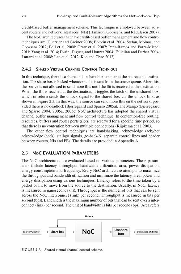
2.4.2 ShareD virtual Channel Control teChnique
In this technique, there is a share and unshare box counter at the source and destina-tion. The share box is locked whenever a flit is sent from the source queue. After this, the source is not allowed to send more flits until the flit is received at the destination. When the flit is reached at the destination, it toggles the latch of the unshared box, which in return sends the unlock signal to the shared box via the unlock link, as shown in Figure 2.3. In this way, the source can send more flits on the network, pro-vided there is no deadlock (Bjerregaard and Sparso 2005a). The Mango (Bjerregaard and Sparso 2004, 2005a, 2005c) NoC architecture has adopted the shared virtual channel buffer management and flow control technique. In contention-free routing, resources, buffers and router ports (slots) are reserved for a specific time period, so that there is no contention between multiple connections (Rijpkema et al. 2003).
The other flow control techniques are handshaking, acknowledge (ack)/not acknowledge (nack), stall/go signals, go-back-N, separate control lines and header between routers, NIs and PEs. The details are provided in Appendix A.
2.5 noC EVALUATION PARAMETERS
The NoC architectures are evaluated based on various parameters. These param-eters include latency, throughput, bandwidth utilization, area, power dissipation, energy consumption and frequency. Every NoC architecture attempts to maximize the throughput and bandwidth utilization and minimize the latency, area, power and energy dissipation using various techniques. Latency refers to the time taken by a packet or flit to move from the source to the destination. Usually, in NoC, latency is measured in nanoseconds (ns). Throughput is the number of bits that can be sent across the NoC interconnect (link) per second. Throughput is measured in bits per second (bps). Bandwidth is the maximum number of bits that can be sent over a inter-connect (link) per second. The unit of bandwidth is bits per second (bps). Area refers
Unsharebox
FIGURE 2.3 Shared virtual channel control scheme.

21In-Depth Review of Network on Chip
to the size of the NoC after synthesis. Nowadays, there are also some software tools that can measure the area and power consumption of the NoC architecture. The unit of area used by most architectures is mm2. The units of energy and power consump-tion used by most architectures are milliwatt (mW) and petajoules (pJ), respectively. When packets traverse the router and interconnect, they consume power and energy.
These parameters are critical to calculate as more heterogeneous devices (PEs) come onto chips. They increase the power and area consumption of the chip. Appendix A shows the parameters by which different NoC architectures are evaluated.
2.6 noC CLOCKING MECHANISM
Communication between routers, NIs and PEs are mostly asynchronous, synchro-nous, globally asynchronous and locally synchronous (GALS), mesochronous, ple-sichronous and heterochronous. The trends show that the NoC architectures are moving from synchronous communication to asynchronous communication. The rea-son is that asynchronous communication is faster and activity dependent, exploiting average-case rather than worst-case performance (Amde et al. 2005; Ben-Itzhak et al. 2012; Emerson 1997). Designing asynchronous NoC is modular, but it is more com-plex compared to synchronous NoC (Emerson 1997). Designing a glitch-free circuit that at the same time manages multiple clocks is more difficult to manage than global clock–based communication. This leads to the idea of synchronous and asynchronous NoC communication by having a GALS architecture. The GALS architecture solves the timing issues in multiple PEs in a NoC because local synchronous PEs need not synchronize with a single global clock. The GALS approach consumes less power compared to the global clock approach, as local PEs have more control over their clocks independently from other synchronous PEs (Agarwal, Iskander, and Shankar 2009). Depending on the requirements of the application mapped on the NoC, the synchronous, asynchronous or GALS architecture will support it and will increase the performance of the NoC. The clock frequency of the NoC architectures is also shown in Appendix A. The frequency is measured in hertz (Hz). The scale of the frequency used by the NoC architectures is megahertz (MHz) and gigahertz (GHz).
2.6.1 SynChronouS noC
In synchronous NoC, communication and activities between multiple components are synchronized based on a single centralized clock. The benefit of synchronous communication is that all of the changes at the routers, PEs and links occur at the same time at a regular clock period. The drawback of this mechanism is clock skew, lack of modularity, electromagnetic interference, worst-case performance and clock power consumption issues (Amde et al. 2005). Examples of synchronous NoCs are (Guerrier and Greiner 2008; Rijpkema et al. 2003; Liang, Swaminathan, and Tessier 2000; Bolotin et al. 2004; Leroy et al. 2005; Hilton and Nelson 2006; Paukovits and Kopetz 2008; Stefan, Molnos, and Goossens 2012; Dally and Towles 2001; Henriksson, Wiklund, and Liu 2003; Bertozzi and Benini 2004; Zeferino, Kreutz, and Susin 2004; Mullins, West, and Moore 2006; Castells-Rufas et al. 2009; Bell et al. 2008; Gratz et al. 2007; Soteriou et al. 2006; Stensgaard and Sparsø 2008;

22 Bio-Inspired Fault-Tolerant Algorithms for Network-on-Chip
Samman, Hollstein, and Glesner 2009; Feero and Pande 2008; Lan et al. 2011; Logvinenko, Gremzow, and Tutsch 2013; Postman et al. 2012; Yaghini, Eghbal, and Bagherzadeh 2015; Penolazzi and Jantsch 2006; Millberg et al. 2004; Kavaldjiev, Smit, Jansen et al. 2006; Chi and Chen 2004; Kim, Kim, and Sobelman 2005; Bouhraoua and Elrabaa 2006; Sanusi and Wang 2006; Lee et al. 2006; Butts 2007; Wang et al. 2010; Qouneh et al. 2012).
2.6.2 aSynChronouS noC
In asynchronous NoC, activities are performed based on the handshake (control) signals shared between routers (Bjerregaard and Mahadevan 2006; Tatas et al. 2014; Amde et al. 2005; Yaghini et al. 2009). Asynchronous NoCs are also called self-timed NoCs (Bainbridge and Furber 2002). Asynchronous circuit implemen-tation usually takes more area, delay, power consumption and channel bandwidth compared to the synchronous approach because of the explicit sharing of signals (Amde et al. 2005). It is not easy to resynchronize the asynchronous communica-tion. The resynchronization introduces error bits and increases the latency and power consumption (Bjerregaard and Mahadevan 2006). The asynchronous communica-tion is faster compared to synchronous communication at high traffic loads, as it has the least latency (Bjerregaard and Mahadevan 2006; Ben-Itzhak et al. 2012). In asynchronous NoC, there can be no timing relationship between synchronous clocks (PEs). Asynchronous provides the maximum flexibility in terms of timing (Teehan, Greenstreet, and Lemieux 2007). When interconnects are idle, apart from the leakage, no power is consumed in asynchronous NoC. This solves the problem of increasing power consumption, as the chip size is increased (Bjerregaard and Mahadevan 2006). The examples of asynchronous NoCs are (Moraes et al. 2004; Rijpkema et al. 2003; Chang, Shen, and Chen 2006; Bainbridge and Furber 2002; Pande et al. 2003; Zeferino and Susin 2003; Samuelsson and Kumar 2004; Bartic et al. 2005; Kumar et al. 2008; El-Moursy, Korzec, and Ismail 2009; Krasteva, De la Torre, and Riesgo 2010; Wu, Tang, and Hsu 2011; Peña-Ramos and Parra-Michel 2011; Mishra, Nidhi, and Kishore 2012; Shu et al. 2012; Al Faruque, Ebi, and Henkel 2010; Choudhary and Qureshi 2012; Evain, Diguet, and Houzet 2004; Coppola et al. 2004; Feliciian and Furber 2004; Bjerregaard and Sparso 2004, 2005a, 2005c; Wolkotte et al. 2005; Beigné et al. 2005; Mondinelli, Borgatti, and KOVACS VAJNA 2004; Ching, Schaumont, and Verbauwhede 2004; Amde et al. 2005; Lattard et al. 2008; Lee et al. 2012).
2.6.3 gloBally aSynChronouS loCally SynChronouS noC
In the GALS approach, the NoC is divided among multiple subsystems. Each subsys-tem has its own clock, and they communicate with other systems through asynchro-nous NoC communication. GALS has less power consumption compared to using a global clock. It avoids the problem of clock synchronization due to clock skew, as more and more devices are coming onto the chip (Amde et al. 2005; Teehan, Greenstreet, and Lemieux 2007; Sigüenza-Tortosa, Ahonen, and Nurmi 2004). Figure 2.4 shows the GALS architecture where independent synchronous islands of systems are

23In-Depth Review of Network on Chip
connected with asynchronous NoCs through irregular topologies. Examples of NoC architectures that follow the GALS approach are (Lines 2004; Castells-Rufas, Joven, and Carrabina 2006; Wang, Ahonen, and Nurmi 2007; Janarthanan and Tomko 2008; Hansson, Subburaman, and Goossens 2009; Siguenza-Tortosa and Nurmi 2002; Kumar et al. 2002; Janarthanan, Swaminathan, and Tomko 2007; Göhringer et al. 2010; Yang et al. 2014; Arteris 2005; Beigné et al. 2009; Liang et al. 2004; Lee et al. 2004; Schoeberl 2007).
In the mesochronous scheme, all the subsystems have different clocks with the same frequency but the phase is different (Wiklund and Liu 2003). This avoids the problem of clock skew. The examples of mesochronous NoC architectures are (Rijpkema et al. 2003; Lee, Lee, and Yoo 2006; Vangal et al. 2008; Wiklund and Liu 2003; Panades, Greiner, and Sheibanyrad 2006; Lee et al. 2005). In plesichronous NoC, the source and destination PE operate at the nominal frequency, which may be slightly different, and this leads to a drifting phase (Teehan, Greenstreet, and Lemieux 2007). The star connected OCN (Lee et al. 2003) is a plesichronous NoC. In a heterochronous NoC, the source and destination have totally different clock fre-quencies (Teehan, Greenstreet, and Lemieux 2007). Some of the NoC architectures have not been mentioned, or it is not clear which clocking scheme they are using. Further details can be found in Appendix A.
FIGURE 2.4 GALS clocking scheme.

24 Bio-Inspired Fault-Tolerant Algorithms for Network-on-Chip
2.7 noC TOPOLOGIES
The topology of the NoC defines how the PEs, routers and links are connected with each other in the network. The selection of a particular topology for any specific NoC depends on the communication usage of the PEs. Other factors in choosing a particular topology for any NoC design include its impact on performance and cost parameters. The performance parameters include latency, fault tolerance, bandwidth and throughput, while cost parameters include area and power consumption (Ogras, Hu, and Marculescu 2005; Stefan, Molnos, and Goossens 2012). Many different topologies have been proposed (Wang et al. 2011), and there are broadly two cat-egories: regular and irregular topologies. In regular topologies, routers and PEs are connected according to some patterns, for example, mesh, torus, fat tree, butterfly fat tree, octagon, star, hierarchical star, crossbar, ring, spidergon, chain, subnets and generalized de Bruijn topology. However, there is no standard pattern in an irregular topology, which may include hybridized topologies. Although regular NoC topolo-gies are simple to implement, at times they have the drawback of being nonoptimal in terms of network utilization. The low network utilization leads to delayed com-munication and increased power consumption. Irregular topologies are used in the literature to overcome these drawbacks. The irregular or custom NoC topologies are application-specific and mostly have heterogeneous PEs and routers compared to regular NoC topologies (Tatas et al. 2014). Regular topologies make the routing deci-sion simple, and it is easily replicated on multiple nodes, while irregular topologies make the routing algorithm more complex (Guerrier and Greiner 2008).
In the mesh topology, the routers are connected to each other through a point-to-point connection in a mesh structure, as shown in Figure 1.1. The routers at the first and last column or row of the NoC are not connected with any other neighboring routers. Most of the NoC architectures have a mesh topology because its communi-cation structure is less complicated and it is also similar to a 2D silicon surface (Seifi and Eshghi 2012; Teehan, Greenstreet, and Lemieux 2007). One of the drawbacks of the mesh topology is congestion at the center of the NoC due to the routing algo-rithm (Tatas et al. 2014). In a mesh topology, the routing algorithm should have an equal and balanced traffic distribution mechanism. The torus topology is similar to the mesh except that the first and last column or row elements are also connected with each other, as this increases and eases the routing decisions. The torus topol-ogy solves the excessive round end trip delays, as they are connected together. The drawback of the torus topology is more area and links requirement than the mesh NoC (Wang et al. 2011). Figure 1.3 and Figure 1.4 show the torus and irregular NoC topologies. In tree structure topologies, the routers are connected in a hierarchical design such that the parent’s routers have child routers connected with them. The PEs are connected to leaf routers, as shown in Figure 1.3. The tree topology is hier-archical in structure but becomes complex as more PEs are joined at the leaf routers (Guerrier and Greiner 2008). In tree-based topology, the traffic can be quickly dis-seminated to the desired destination due to the hierarchical structure (Bjerregaard and Mahadevan 2006).
In the star topology, the routers are connected with a centralized arbiter. The arbiter manages communication between multiple routers. The arbiter may be a

25In-Depth Review of Network on Chip
specialized device, or it can be a router as well (Lee et al. 2003). The capacity of the centralized arbiter/router should be significant to manage the traffic received from the multiple PEs connected to it. At times this also leads to congestion at the centralized switch (Tatas et al. 2014). In the octagon topology, however, eight routers are connected in a ring fashion with the bidirectional wires (Karim, Nguyen, and Dey 2002). The octagon topology is simple to implement. Fast and efficient routing algorithms can be implemented using this topology. Excessive wiring is required to extend the octagon network to more than eight PEs (Tatas et al. 2014). In the crossbar topology, the routers are connected with several wires in a crossbar fashion. This topology is simple to implement, but the links between PEs become complex and broad as more PEs are connected (Lines 2004). Ring topology refers to the nodes connected in a ring (Samuelsson and Kumar 2004), and all routers are connected with each other through interconnects in a ring shape, as shown in Figure 1.4. Although the ring topology is simple to implement, it has limited scalability and performance problems as the number of nodes is increased (Tatas et al. 2014).
In the spidergon topology, several nodes (more than two) are connected together in a bidirectional ring in both clockwise and counterclockwise directions. In this way, the nodes in the spidergon are connected with a cross-connection. The spider-gon topology is similar to a spider web. This topology is regular, scalable, point-to-point and has a suitable network diameter. The network becomes complex as the number of PEs is increased (Coppola et al. 2004). In the subnet topology, small groups of PEs are connected with the router, which are called the subnets. These subnets in turn are connected to each other. The PEs that communicate often are put in the same subnet. This makes communication between PEs more efficient. The communication between PEs in different subnets takes more time, which may lead to delayed communication (Hilton and Nelson 2006).
In the de Bruijin topology, the nodes are connected through vertices, and it can be an irregular topology (Soteriou et al. 2006). It is, however, an efficient topology for parallel processing and is also suitable for very large-scale integration (VLSI) implementation. The two-dimensional de Bruijin NoC performs better compared to the two-dimensional mesh topology in terms of latency and energy dissipation. At times, in two-dimensional de Bruijin the NoC takes more links to connect the neighbor node compared to the two-dimensional meshes, and this increases the net-work area (Sabbaghi-Nadooshan, Modarressi, and Sarbazi-Azad 2010). The details of NoC architectures that have a specific topology are given in Appendix A.
2.8 OPEN SOURCE
The open-source software/architecture has a license allowing the end user to have access to the source code, redistribute the software/architecture and modify the orig-inal code with the same license. At times, the license may have special provisions. For example, the derived software/architecture should use its own name and version apart from mentioning the original software/architecture name. Open-source archi-tectures and codes are commonly provided for academic and research purposes. They are mostly not allowed to be used for commercial purposes.

26 Bio-Inspired Fault-Tolerant Algorithms for Network-on-Chip
Æthereal (Rijpkema et al. 2003), Aelite (Hansson, Subburaman, and Goossens 2009) and dAElite (Stefan, Molnos, and Goossens 2012) architectures are not open source. However, Nostrum (Penolazzi and Jantsch 2006; Millberg et al. 2004) is provided on request. Reconfigurable Network on Chip (Ching, Schaumont, and Verbauwhede 2004) and NocMaker (Castells-Rufas et al. 2009) are open-source architectures. The specific details are given in Appendix A.
2.9 noC CONNECTION TYPES
Connection type refers to the way a source PE is connected with the destination PE. The connections can be simple, narrowcast, multicast or broadcast. The multicast communication produces a significant amount of redundant traffic that increases latency and congestion in the NoC compared to unicast communication. By com-bining multiple unicast connections, multicast communication can be constructed to overcome the drawbacks of multicast communication. Various multiproces-sor System on Chip (MPSoC) applications use multicast communication, which includes replication, barrier synchronization, and cache coherency in a distributed shared memory architecture (Palesi and Daneshtalab 2014). Figure 2.5 shows the three connection types.
2.9.1 SimPle ConneCtion
1–1, or simple connection, is between one source PE and one destination PE (Radulescu and Goossens 2004). A few architectures that provide simple communi-cation between PEs are (Guerrier and Greiner 2008; Moraes et al. 2004; Rijpkema et al. 2003; Liang, Swaminathan, and Tessier 2000; Karim, Nguyen, and Dey 2002; Lines 2004; Hansson, Subburaman, and Goossens 2009; Stefan, Molnos, and Goossens 2012; Bainbridge and Furber 2002; Pande et al. 2003; Henriksson, Wiklund, and Liu 2003; Bertozzi and Benini 2004; Samuelsson and Kumar 2004; Castells-Rufas et al. 2009; Gratz et al. 2007; Vangal et al. 2008; Kumar et al. 2008; El-Moursy, Korzec, and Ismail 2009; Göhringer et al. 2010; Krasteva, De la Torre, and Riesgo 2010; Wu, Tang, and Hsu 2011; Peña-Ramos and Parra-Michel 2011; Grot et al. 2011; Mishra, Nidhi, and Kishore 2012; Shu et al. 2012; Logvinenko, Gremzow, and Tutsch 2013; Arteris 2005; Wiklund and Liu 2003; Penolazzi and Jantsch 2006; Millberg et al. 2004; Bjerregaard and Sparso 2004, 2005a, 2005c; Wolkotte et al. 2005; Kavaldjiev, Smit, Jansen et al. 2006; Panades, Greiner, and Sheibanyrad 2006; Liang et al. 2004; Hu and Marculescu 2004; Schoeberl 2007; Lee et al. 2012; Bahirat and Pasricha 2014).
2.9.2 narrowCaSt ConneCtion
A connection becomes narrowcast if one source PE is connected with one or multi-ple destinations PEs. In this connection, the instruction initiated by the source is only executed by one destination PE. The destination can send a return message to the source PE to acknowledge the instruction or data sent by the source PE. Narrowcast connections are bidirectional between the source and destination (Radulescu and Goossens 2004).

27In-Depth Review of Network on Chip
2.9.3 multiCaSt ConneCtion
These connections are between a source PE and one or more destinations PEs. In these connections, instructions or data sent by the source are duplicated, and the copies are sent to every destination PE. As these connections are unidirectional, no return messages are allowed from the destination PE to the source PE. Return messages are also not allowed due to memory limitations. Multicast connections are unidirectional (Radulescu and Goossens 2004). The examples of NoC archi-tectures providing multicast connections are (Rijpkema et al. 2003; Salminen et al. 2006; Wang, Ahonen, and Nurmi 2007; Hansson, Subburaman, and Goossens 2009; Stefan, Molnos, and Goossens 2012; Bainbridge and Furber 2002; Pande et al. 2003;
FIGURE 2.5 Simple, narrowcast and multicast connections.

28 Bio-Inspired Fault-Tolerant Algorithms for Network-on-Chip
Kumar et al. 2008; Samman, Hollstein, and Glesner 2009; Krasteva, De la Torre, and Riesgo 2010; Wu, Tang, and Hsu 2011; Grot et al. 2011; Ganguly et al. 2010; Penolazzi and Jantsch 2006; Millberg et al. 2004; Bjerregaard and Sparso 2004, 2005a, 2005c; Schuck, Lamparth, and Becker 2007; Liang et al. 2004; Kao and Chao 2012).
2.9.4 BroaDCaSt CommuniCation anD multiPath routing
As the names imply, with these types of communication, a source PE can send packets to every destination PE attached with it directly or indirectly (Guerrier and Greiner 2008). SPIN (Guerrier and Greiner 2008), Nexus (Lines 2004) and TTNoC (Schoeberl 2007) are a few architectures that support broadcast communication. Multipath routing uses multiple paths available to route packets from source to desti-nation. CLICHÉ (Kumar et al. 2002), on the other hand, provides multipath routing. The specific details can be found in Appendix A.
2.10 noC SIZE
NoC architectures have used a number of different NoC sizes for implementation purposes. It is because NoC is modular, scalar and the implementation on one NoC size can easily be applied to different NoC sizes. These sizes include 2 × 2, 3 × 3, 4 × 4, 5 × 5, 6 × 6, 7 × 7, 8 × 8, 5 × 8, 2 × 3 and 4 × 3, having two-dimensional mesh and torus topologies. Some of the NoC topologies are regular, while others are irregular. The details are provided in Appendix A about NoC architectures supporting par-ticular NoC sizes.
2.11 noC IMPLEMENTATION PLATFORMS
The NoC architectures are implemented using the simulator, field programmable gate array (FPGA) and application-specific integrated circuits (ASIC). Using a cycle accurate simulator, some NoC architectures have been synthesized. The simulators used are OMNET++ (Varga and Hornig 2008), NS-2, OPNET, Noxim, Nirgam (Jain et al. 2007), Simics, Garnet (Agarwal et al. 2009), Orion (Wang et al. 2002), Spice, Recsim (Logvinenko and Tutsch 2012) and CACTI (Muralimanohar, Balasubramonian, and Jouppi 2007). The details of NoC architectures using a spe-cific simulator can be found in Appendix A.
2.12 noC BUFFERING MECHANISMS
A buffer is an integral part of any network router (Bjerregaard and Mahadevan 2006), but it consumes more power in the NoC. Therefore, an efficient buffer design is essential for optimized NoC performance (Tatas et al. 2014). The design includes the location and size of the buffer (Bjerregaard and Mahadevan 2006). To minimize the access latency and implementation cost, it is always preferred to use registers rather than huge memories in the form of static random access memory (SRAM) or

29In-Depth Review of Network on Chip
dynamic random access memory (DRAM) (Hu and Marculescu 2003). The location of the buffers can be at the input or output port of the router. These buffers are called the input queue and output queue. The performance of the output buffer is the best compared to other strategies, but at the cost of more loads on interconnects. When to read the flits from the input or output queue depends on the Scheduler, which in turn checks the output port to see whether it is free. Usually, routers used to have one queue per port, but due to the Head of Line (HOL) problem, now they have more than one queue per port for every connection. The virtual output queue (VOQ) is one type of input buffering that has the combined benefits of input and output queu-ing (Rijpkema et al. 2003). The input queues may have less memory cost, as they have fewer queues compared to VOQ and output buffers (Radulescu and Goossens 2004). Input queues also solve the problem of HOL, as the output queues may be blocked due to congestion or faulty interconnects (Bjerregaard and Mahadevan 2006). Figure 2.6 shows the output and VOQ architectures of routers. Most of the NoC architectures prefer input and a combined input and output buffers because of the better link utilization and performance. The area of the NoC increases directly as the size of the input buffers is increased. In (Ogras, Hu, and Marculescu 2005), it is mentioned that the 4 × 4 NoC area increases by 30% as the input buffer size is increased from two to three words. But at certain times, depending on the network load, the network latency is reduced in a considerable amount by increasing the buf-fer size. However, due to the heterogeneous traffic generated by PEs in the NoC, it is always desirable to allocate more buffers for high-traffic channels, whereas a small number of buffers can be allocated to low-traffic channels. Specific details on NoC architectures can be found in Appendix A.
2.13 noC PE–ROUTER INTERFACE
The interface between the PE and router through the NI either is through a bidi-rectional bus or follows a particular standard interface. The standard interfaces are AMBA AHB, AMBA APB, AMBA AXI, VCI, PVCI, BVCI, AVCI and OCP that follow a particular procedure and signals for reading and writing data from the source PE and destination PE. Appendix A shows the NoC architectures that have adopted these interfaces.
FIGURE 2.6 (a) Output queue and (b) VOQ router architecture.

30 Bio-Inspired Fault-Tolerant Algorithms for Network-on-Chip
2.13.1 aDvanCeD miCroController BuS arChiteCture
Advanced Microcontroller Bus Architecture (AMBA) is an on-chip interconnect specification. The AMBA family (1, 2, 3, 4, 5) standard helps to manage the connec-tions and data movement between PEs in the NoC.
AMBA defines three types of buses for high-performance communication. These are the advanced system bus (ASB), advanced high-performance bus (AHB) and an advanced peripheral bus (APB). ASB supports multiple bus masters, high burst and pipelined transfer operations (Mitić and Stojčev 2006b). AHB is for those sys-tem modules that work at high frequency and have high bandwidth communica-tion requirements. AHB supports multiple bus master operations, split transactions, peripheral and burst transfer and nontristate implementation. APB is for those devices that operate at low power, and it connects general-purpose low-speed devices (Mitić and Stojčev 2006b; Specification 1999). All devices connected with the peripheral bus master (bridge) are called slaves. APB is a static bus, and it supports simple addressing. Figure 2.7 shows that AMBA buses are hierarchically organized in two bus segments. System and peripheral buses are connected together through a bridge that sends data between these two segments. AMBA buses do not define any arbitra-tion rules; instead, the arbiter can decide the application needs (Mitić and Stojčev 2006b).
The AMBA advanced extensible interface (AXI) protocol is for high-perfor-mance and high frequency systems. It is an advanced version of AHB, ASB and
FIGURE 2.7 AMBA buses in a system.

31In-Depth Review of Network on Chip
APB, and belongs to the AMBA 2 family. AMBA has also released the latest version of AXI in the AMBA 3 protocol family. AXI is based on point-to-point connec-tions (Mitić and Stojčev 2006b). The AMBA advance trace bus (ATB) is part of the AMBA 4 family released in 2012, and it spelled out the rules of how traces are shared in a trace system between its modules (Benini and Bertozzi 2005). Finally, the Coherent Hub Interface (CHI) is the new SoC protocol in the AMBA 5 family. CHI provides the better performance required by servers and networking applica-tions (ARM). Every family of AMBA is better than the previous one and provides more enhanced features.
2.13.2 oPen Core ProtoCol
Open Core Protocol (OCP) is an interface standard that connects PEs to an on-chip bus. It is an openly licensed protocol. It defines the rules of communication between two modules. The two modules can be a PE and an NI (Tatas et al. 2014). OCP sup-ports a master–slave interface with unidirectional signals. It is fully synchronous and driven by the rising edge of the clock. It supports data transfer on every clock cycle. In OCP, signals are point-to-point except the clock and reset signals. OCP allows the master and slave to control the transfer rate (Mitić and Stojčev 2006a). The drawback of OCP is that Altera and Xilink, the two largest FPGA vendors, do not support this protocol. Figure 2.8 shows the SoC design based on the OCP protocol. The NoC architectures with OCP interfaces are (Moraes et al. 2004; Chang, Shen, and Chen 2006; Salminen et al. 2006; Wang, Ahonen, and Nurmi 2007; Wingard 2001; Bainbridge and Furber 2002; Zeferino and Susin 2003; Bertozzi and Benini 2004; Hoffman et al. 2007; Arteris 2005; Bjerregaard and Sparso 2004, 2005a, 2005c; Panades, Greiner, and Sheibanyrad 2006).
FIGURE 2.8 SoC design using OCP protocol.

32 Bio-Inspired Fault-Tolerant Algorithms for Network-on-Chip
2.13.3 virtual SoCket interFaCe allianCe (vSia)
PROTEO (Siguenza-Tortosa and Nurmi 2002) follows the standard VSIA-compliant interface, which includes three different virtual component interfaces (VCIs). They are peripheral VCI (PVCI), basic VCI (BVCI) and advanced VCI (AVCI). VCI is an interface, and it specifies the request–response protocol, a set of instructions for transferring request–response messages and the content of these messages. PVCI is a simple interface and is easily implementable compared to BVCI. BVCI is suitable for most applications. It is a very powerful protocol, but not very complex. AVCI is an advanced version of BVCI with more advanced features of the threads. AVCI sup-ports high-performance applications. Figure 2.9 shows a point-to-point connection between the initiator and target using VCI. The initiator issues a request, while the target replies with a response signal. VCI can be connected to a bus using an inter-face wrapper, as shown in Figure 2.10. The initiator is connected via a VCI interface to the bus initiator. The bus initiator wrapper is connected with the bus. Similarly, on the target side, the bus wrapper is used. At the initiator bus wrapper, the VCI target and bus master are used, while at the target side, a bus slave and VCI initiator are used (Mitić and Stojčev 2006a). Examples of NoC architectures that have VCI inter-faces are (Guerrier and Greiner 2008; Wang, Ahonen, and Nurmi 2007; Zeferino and Susin 2003; Evain, Diguet, and Houzet 2004; Panades, Greiner, and Sheibanyrad 2006; Lee, Lee, and Lee 2004).
According to the literature, most of NoC architectures have not mentioned the type of interface. Only twelve architectures use OCP interfaces, while seven use the VSIA interface. The AMBA family interfaces are adopted by three NoC architec-tures. Other on-chip buses are Avalon, CoreConnect, STBus, Wishbone, CoreFrame, Marble, PI Bus and the SiliconBackplane network (Mitić and Stojčev 2006a).
2.14 noC FREQUENCY AND TECHNOLOGY
The NoC frequency refers to the clock frequency of the NoC. There are different clocking mechanisms based on which NoC is synchronized. They are asynchronous, synchronous, GALS, mesochronous, plesichronous and heterochronous (Teehan, Greenstreet, and Lemieux 2007). The frequency is measured in Hz. The scale of the frequency used by the NoC architectures is measured in MHz and GHz. The frequency of the NoC architecture specifies how quickly it can process the instruc-tions and data. Appendix A specifies the frequency parameters of NoC architectures. Most of the NoC architectures have specified the frequency at which they operate, but only thirty-three architectures do not specify the clock frequency.
FIGURE 2.9 Point-to-point connection in VCI.

33In-Depth Review of Network on Chip
Technology refers to the feature size. Feature size is the minimum size of a transistor or a wire. NoC architectures are implemented in micrometers (µm) and nanometer (nm) technologies. Forty-three percent of the NoC architectures have not mentioned the technology on which their NoC architectures are implemented.
These features might help the research community to shortlist the NoC architec-ture based on the frequency and feature size, depending on their specific application requirements and do further research on it.
2.15 noC AREA AND POWER CONSUMPTION
Area refers to the size of the NoC on the system on a chip, on an FPGA or on ASIC. Some of the NoC architectures have mentioned the area of the complete NoC, whereas a few of them have specified the area of the router or switch. The area is usually measured as the total number of lookup tables or slices used in FPGA or the number of gates/transistors/flip-flops/logic cells used in the NoC architecture. Some of the NoC architectures have specified the area of the NoC in mm2 and µm2. The details regarding specific NoC architectures’ areas are presented in Appendix A. In embedded systems, the area and power consumption of the devices are vital.
FIGURE 2.10 Point-to-point connection in VCI using a bus.

34 Bio-Inspired Fault-Tolerant Algorithms for Network-on-Chip
It is an open research area for developing techniques to efficiently utilize these two parameters.
The NoC clocking mechanism, buffer management, routing algorithms and switching activities consume power and energy on a per-router and interconnect basis. The details regarding these parameters related to specific NoCs are provided in Appendix A. The units used for power dissipation are µW (microwatt), mW (mil-liwatt), W and MW (megawatt), while the units used for energy consumption are pj (petajoule) and pj/packet (petajoule per packet).
2.16 noC ROUTER PORTS AND BUS WIDTH
The number of ports in the switch improves the performance of the NoC, but it might also increase the complexity of the NoC. The number of ports in the switch also depends on the topology being used in the NoC. The area consumption of the router increases as the number of ports is increased (Tatas et al. 2014). The number of ports and topology should be optimally selected to improve the overall performance of the NoC. For a mesh topology, five ports are connecting four immediate neighbors and one to the local core (PE). For tree and other topologies, it can be a different num-ber of ports based on the NoC configuration. In 3D architectures, two more ports are connecting the upper and lower layers of the NoC. QORE (DiTomaso, Kodi, and Louri 2014) has the highest number of router/switch ports (i.e., twenty), while the minimum number of ports is three. The details of other NoC architectures can be found in Appendix A. The number of router ports has a significant effect on the topology of the NoC. This, in turns, affects the bandwidth, throughput, latency and power consumption of the NoC. Information regarding the number of ports is essen-tial for the NoC. Sixty-three percent of NoC architectures have provided information regarding the router ports.
Bus or channel width is the number of bits that can be sent over the channel. It controls the number of bits that can be sent over the channel from multiple sources and destinations. This parameter affects the congestion, deadlock, bandwidth and throughput utilization of the NoC. Usually, the bus width is equal to the flit size. Bus width also affects the complexity, latency, power and area consumption of the NoC (Tatas et al. 2014; Marculescu et al. 2008; Brugge and Khalid 2014). To have an optimal channel width at times is not possible, as it is dependent on the application and other factors involved in the NoC (Marculescu et al. 2008). Different NoC archi-tectures have a different channel and data bus width. Only 45% of NoC architectures have provided details regarding bus or channel width. Details about the channel width of different NoC architectures are given in Appendix A.
2.17 noC YEAR OF PROPOSAL, FLIT SIZE AND LATENCY
The NoC architectures have been proposed from 2000 to 2019. Some of the archi-tectures are big and well defined, while others are used for particular applications. In 2000, the first NoC architecture SPIN (Guerrier and Greiner 2008) was proposed. This NoC architecture supported synchronous packet switching. It had wormhole switching and credit-based buffer management technique for flow control and buffer

35In-Depth Review of Network on Chip
management. It possessed a fat tree topology and enabled 1–1 and broadcast com-munication. The SPIN (Guerrier and Greiner 2008) NoC architecture laid the foun-dation for further research in the area of on-chip network communication. Later, in 2001, Dally et al. (Dally and Towles 2001) proposed the on-chip network and router architecture. In 2002, Luci Benini named this on-chip network “Network on Chip” (Benini and De Micheli 2002). That year was the cornerstone for further research in the NoC area. Research flourished on the different aspects of NoC, which include dif-ferent topologies, routing algorithms, buffer management, quality of service (QoS) parameters, clocking mechanisms, fault tolerance, switching techniques, congestion avoidance and management techniques, multiple connection types and other areas. Appendix A shows the year-based information for the various NoC architectures.
Flit stands for “flow control digits.” It is the smallest unit of a packet. Packets are divided into a header, body and tail flit for efficient routing, bandwidth and throughput utilization. The size of the flit affects the latency, channel (bus) width and power con-sumption of the NoC. Appendix A shows the different NoC architectures that have dif-ferent flit sizes. Flit size is commonly measured in bits. Some of the NoC architectures have the packet size in flits and bits. The message generated by the source PE contains packets, which are divided into flits. By keeping the flit size the same and shrinking the size of the feature as technology scales down, the overall area of the router is decreased but power consumption is increased. Therefore, technology scaling does not allow the width of the flit to be increased. The cost (area and power consumption) of the router increases along with the flit size. The NoC saturation point is reached early as the flit size is continuously increased. The general rule of thumb is to peg the size of the flit to the size of the shortest packet. To increase the throughput of the NoC, one way is to increase the flit size, but this is not a cost-effective solution, as it may lead to an issue of fragmentation (Lee et al. 2013). The flit size in HERMES (Moraes et al. 2004) and AdNoC (Al Faruque, Ebi, and Henkel 2010) is 8 bits. The flit size is 16 bits for Dally et al. (Dally and Towles 2001), CHAIN (Bainbridge and Furber 2002), QNoC (Bolotin et al. 2004), On-Chip Multimedia Applications (Lee et al. 2006) and BMNoC (Lee et al. 2012) NoC architectures. The following NoC architectures (Guerrier and Greiner 2008; Liang, Swaminathan, and Tessier 2000; Bertozzi and Benini 2004; Hoffman et al. 2007; Arteris 2005; Beigné et al. 2009; Hu and Marculescu 2004) have 32-bit flits. Similarly, the flit size is 34 bits for A Reconfigurable Baseband Platform Based on Asynchronous NoC (Lattard et al. 2008) and ReNoC (Stensgaard and Sparsø 2008). In Intel TeraFLOPS (Vangal et al. 2008), the flit size is 38 bits. The flit size is 42 bits for BIDI-MIN (Pande et al. 2003). For Polaris (Soteriou et al. 2006) and BLOCON (Kao and Chao 2014), the flit size is 64 bits. In MicroNetwork (Wingard 2001) the flit size is 128 bits, while HELIX (Bahirat and Pasricha 2014) has a flit size of 256 bits. In CLICHÉ (Kumar et al. 2002), the packet size is 256 bits, whereas Æthereal (Rijpkema et al. 2003) has a flit size of 8 flits.
Latency is the time required to send a flit from the source PE to destination PE. The latency of the flit and packet depends on the time taken by the router and interconnects to deliver it to a neighboring router or interconnect. Latency also depends on the flit size, channel or bus width, topology and communication standards of NoC (Marculescu et al. 2008). In Appendix A, latency is measured in cycles, nanoseconds (ns), micro-seconds (µs) and picoseconds (ps) in different NoC architectures. Most of these NoC
36 Bio-Inspired Fault-Tolerant Algorithms for Network-on-Chip
architectures have not provided this information. Forty-two percent of NoC architec-tures have specified latency information. The details are mentioned in Appendix A.
2.18 QUALITY OF SERVICE
Guaranteed throughput/guaranteed service (GT/GS) and best-effort services (BE) are two broad categories of services provided in the NoC (Nurmi 2005). The litera-ture shows that most of the NoC architectures offer BE or packet-based quality of service (QoS). Only a few NoC architectures offer GT/GS or both QoS.
2.18.1 guaranteeD throughPut ServiCeS
In GT connections, resources are reserved for a particular time period between a specific source and destination pair. The resources include channel bandwidth, rout-ers and PE time slots. GT connections may underutilize network resources at certain times. This makes the GT connections an expensive option. At certain times, routers and PEs send a burst of data on these GT connections and then remain silent for a certain period of time. This leads to the underutilization of network resources. That is why BE services complement the GT services by utilizing the unused bandwidth. Video processing is an example of a GT connection. This implies that GT con-nections are usually preferred for real time-critical traffic applications (Goossens, Dielissen, and Radulescu 2005; Rijpkema et al. 2003). Examples of the NoC architec-tures that provide GT-based communication services are (Liang, Swaminathan, and Tessier 2000; Karim, Nguyen, and Dey 2002; Lines 2004; Bolotin et al. 2004; Leroy et al. 2005; Hilton and Nelson 2006; Chang, Shen, and Chen 2006; Salminen et al. 2006; Castells-Rufas, Joven, and Carrabina 2006; Wang, Ahonen, and Nurmi 2007; Paukovits and Kopetz 2008; Janarthanan and Tomko 2008; Hansson, Subburaman, and Goossens 2009; Stefan, Molnos, and Goossens 2012).
2.18.2 BeSt-eFFort ServiCeS
Bandwidth is not reserved in BE connections. BE uses the bandwidth unused by the GT connections. Thus, the BE connection does not provide any guarantee of bandwidth. BE connections efficiently utilize the bandwidth and resources, as they are designed for average-case scenarios compared to the GT worst-case mechanism. Examples of BE connections are cache updates. This shows that BE connections are preferred for noncritical traffic (Goossens, Dielissen, and Radulescu 2005; Rijpkema et al. 2003). One of the major drawbacks of the BE services is its unpredictability (Tatas et al. 2014). Examples of NoC architectures that provide BE-based communication ser-vices are (Guerrier and Greiner 2008; Moraes et al. 2004; Wingard 2001; Bainbridge and Furber 2002; Siguenza-Tortosa and Nurmi 2002; Kumar et al. 2002; Taylor et al. 2002; Pande et al. 2003; Henriksson, Wiklund, and Liu 2003; Zeferino and Susin 2003; Bertozzi and Benini 2004; Samuelsson and Kumar 2004; Zeferino, Kreutz, and Susin 2004; Chan and Parameswaran 2004; Bartic et al. 2005; Kim et al. 2005; Neeb and Wehn 2008; Kariniemi and Nurmi 2006; Mullins, West, and Moore 2006; Zid et al. 2006; Lee, Lee, and Yoo 2006; Castells-Rufas et al. 2009; Bell et al. 2008; Gratz
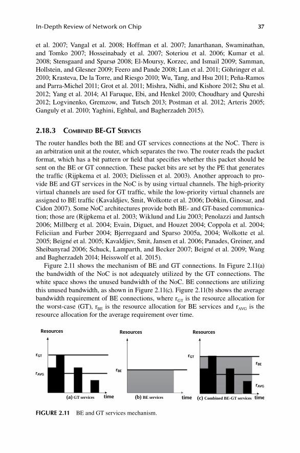
37In-Depth Review of Network on Chip
et al. 2007; Vangal et al. 2008; Hoffman et al. 2007; Janarthanan, Swaminathan, and Tomko 2007; Hosseinabady et al. 2007; Soteriou et al. 2006; Kumar et al. 2008; Stensgaard and Sparsø 2008; El-Moursy, Korzec, and Ismail 2009; Samman, Hollstein, and Glesner 2009; Feero and Pande 2008; Lan et al. 2011; Göhringer et al. 2010; Krasteva, De la Torre, and Riesgo 2010; Wu, Tang, and Hsu 2011; Peña-Ramos and Parra-Michel 2011; Grot et al. 2011; Mishra, Nidhi, and Kishore 2012; Shu et al. 2012; Yang et al. 2014; Al Faruque, Ebi, and Henkel 2010; Choudhary and Qureshi 2012; Logvinenko, Gremzow, and Tutsch 2013; Postman et al. 2012; Arteris 2005; Ganguly et al. 2010; Yaghini, Eghbal, and Bagherzadeh 2015).
2.18.3 ComBineD Be-gt ServiCeS
The router handles both the BE and GT services connections at the NoC. There is an arbitration unit at the router, which separates the two. The router reads the packet format, which has a bit pattern or field that specifies whether this packet should be sent on the BE or GT connection. These packet bits are set by the PE that generates the traffic (Rijpkema et al. 2003; Dielissen et al. 2003). Another approach to pro-vide BE and GT services in the NoC is by using virtual channels. The high-priority virtual channels are used for GT traffic, while the low-priority virtual channels are assigned to BE traffic (Kavaldjiev, Smit, Wolkotte et al. 2006; Dobkin, Ginosar, and Cidon 2007). Some NoC architectures provide both BE- and GT-based communica-tion; those are (Rijpkema et al. 2003; Wiklund and Liu 2003; Penolazzi and Jantsch 2006; Millberg et al. 2004; Evain, Diguet, and Houzet 2004; Coppola et al. 2004; Feliciian and Furber 2004; Bjerregaard and Sparso 2005a, 2004; Wolkotte et al. 2005; Beigné et al. 2005; Kavaldjiev, Smit, Jansen et al. 2006; Panades, Greiner, and Sheibanyrad 2006; Schuck, Lamparth, and Becker 2007; Beigné et al. 2009; Wang and Bagherzadeh 2014; Heisswolf et al. 2015).
Figure 2.11 shows the mechanism of BE and GT connections. In Figure 2.11(a) the bandwidth of the NoC is not adequately utilized by the GT connections. The white space shows the unused bandwidth of the NoC. BE connections are utilizing this unused bandwidth, as shown in Figure 2.11(c). Figure 2.11(b) shows the average bandwidth requirement of BE connections, where rGT is the resource allocation for the worst-case (GT), rBE is the resource allocation for BE services and rAVG is the resource allocation for the average requirement over time.
FIGURE 2.11 BE and GT services mechanism.

38 Bio-Inspired Fault-Tolerant Algorithms for Network-on-Chip
SUMMARY
Due to the advanced nanoscale manufacturing processes, the communication between the PEs faces various faults on the NoC. The communication requirement in the NoC has increased due to more complex connections. The complexity of NoC interconnects is due to the physical device sizes being scaled down. Various fault-tolerant routing algorithms have been proposed. The fault-tolerant algorithms are deterministic, stochastic, fully adaptive and partial adaptive routing algorithms. However, all of these algorithms do not entirely address the issues of fault tolerance. Biological brain-inspired algorithms have been adapted to make NoCs fault-tolerant and robust. The bio-inspired “synaptogenesis” and “sprouting” algorithms are a self-adopting and self-healing concept from the biological brain. These algorithms were implemented with BE, GT and combined BE-GT services. Two survey studies were conducted to gain in-depth knowledge of the NoC architecture. The NoC architec-tures were evaluated using different parameters, among which fault tolerance was one of the essential parameters.
REFERENCES
AMBA® 3 AXI™ Protocol Checker.AMBA® AXI Protocol Specification, ARM.AMBA™ 4 ATB Protocol Specification, ATBv1.0 and ATBv1.1, ARM.“The network simulator (ns-2).” www.isi.edu/nsnam/ns/.“Noxim, the NoC Simulator.”“OPNET Technologies, Inc. OPNET Modeler.” www.opnet.com.“Simics.”“Spice.”“Virtual Socket Interface Alliance (VSIA).” Accessed 1st March 2016. http://vsi.org/Agarwal, Ankur, Cyril Iskander, and Ravi Shankar. 2009. “Survey of network on chip (NoC)
architectures & contributions.” Journal of Engineering, Computing and Architecture 3 (1):21–27.
Agarwal, Niket, Tushar Krishna, Li-Shiuan Peh, and Niraj K Jha. 2009. “GARNET: A detailed on-chip network model inside a full-system simulator.” 2009 IEEE International Symposium on Performance Analysis of Systems and Software.
Ahmad, Balal, Ahmet T Erdogan, and Sami Khawam. 2006. “Architecture of a dynamically reconfigurable NoC for adaptive reconfigurable MPSoC.” First NASA/ESA Conference on Adaptive Hardware and Systems (AHS’06).
Ahmed, Akram Ben, and Abderazek Ben Abdallah. 2014. “Graceful deadlock-free fault-toler-ant routing algorithm for 3D Network-on-Chip architectures.” Journal of Parallel and Distributed Computing 74 (4):2229–2240.
Ahmed, Akram Ben, and Abderazek Ben Abdallah. 2016. “Adaptive fault-tolerant architecture and routing algorithm for reliable many-core 3D-NoC systems.” Journal of Parallel and Distributed Computing 93:30–43.
Ainsworth, Thomas William, and Timothy Mark Pinkston. 2007. “Characterizing the Cell EIB on-chip network.” IEEE Micro 27 (5):6–14.
Al Faruque, Mohammad Abdullah, Thomas Ebi, and Jörg Henkel. 2010. “AdNoC: Runtime adaptive network-on-chip architecture.” IEEE Transactions on Very Large Scale Integration (VLSI) Systems 20 (2):257–269.
Amde, Manish, Tomaz Felicijan, Aristeidis Efthymiou, Douglas Edwards, and Luciano Lavagno. 2005. “Asynchronous on-chip networks.” IEE Proceedings-Computers and Digital Techniques 152 (2):273–283.

39In-Depth Review of Network on Chip
Anjo, Kenichiro, Yutaka Yamada, Michihiro Koibuchi, Akiya Jouraku, and Hideharu Amano. 2004. “BLACK-BUS: A new data-transfer technique using local address on networks-on-chips.” 2004 18th International Parallel and Distributed Processing Symposium. Proceedings.
ARM. “ ARM.” Accessed 1st October 2019. www.arm.com/products/system-ip/amba/amba-open-specifications.php
Arteris, SA. 2005. “A comparison of network-on-chip and busses.” White Paper.Bahirat, Shirish, and Sudeep Pasricha. 2014. “HELIX: Design and synthesis of hybrid nano-
photonic application-specific network-on-chip architectures.” Fifteenth International Symposium on Quality Electronic Design.
Bahrebar, Poona, and Dirk Stroobandt. 2014. “Adaptive and reconfigurable fault-toler-ant routing method for 2D Networks-on-Chip.” 2014 International Conference on ReConFigurable Computing and FPGAs (ReConFig14).
Bainbridge, John, and Steve Furber. 2002. “Chain: A delay-insensitive chip area interconnect.” IEEE Micro (5):16–23.
Bartic, TA, J-Y Mignolet, Vincent Nollet, Theodore Marescaux, Diederik Verkest, Serge Vernalde, and Rudy Lauwereins. 2005. “Topology adaptive network-on-chip design and implementation.” IEE Proceedings-Computers and Digital Techniques 152 (4):467–472.
Beigné, Edith, Fabien Clermidy, Hélène Lhermet, Sylvain Miermont, Yvain Thonnart, Xuan-Tu Tran, Alexandre Valentian, Didier Varreau, Pascal Vivet, and Xavier Popon. 2009. “An asynchronous power aware and adaptive NoC based circuit.” IEEE Journal of Solid-State Circuits 44 (4):1167–1177.
Beigné, Edith, Fabien Clermidy, Pascal Vivet, Alain Clouard, and Marc Renaudin. 2005. “An asynchronous NoC architecture providing low latency service and its multi-level design framework.” 11th IEEE International Symposium on Asynchronous Circuits and Systems.
Bell, Shane, Bruce Edwards, John Amann, Rich Conlin, Kevin Joyce, Vince Leung, John MacKay, Mike Reif, Liewei Bao, and John Brown. 2008. “Tile64-processor: A 64-core soc with mesh interconnect.” 2008 IEEE International Solid-State Circuits Conference-Digest of Technical Papers.
Benini, Luca, and Davide Bertozzi. 2005. “Network-on-chip architectures and design meth-ods.” IEE Proceedings-Computers and Digital Techniques 152 (2):261–272.
Benini, Luca, and Giovanni De Micheli. 2002. “Networks on chips: A new SoC paradigm.” Computer 35 (1):70–78.
Ben-Itzhak, Yaniv, Eitan Zahavi, Israel Cidon, and Avinoam Kolodny. 2012. “HNOCS: Modular open-source simulator for heterogeneous NoCs.” 2012 International Conference on Embedded Computer Systems (SAMOS).
Bertozzi, Davide, and Luca Benini. 2004. “Xpipes: A network-on-chip architecture for gigas-cale systems-on-chip.” IEEE Circuits and Systems Magazine 4 (2):18–31.
Bjerregaard, Tobias, and Shankar Mahadevan. 2006. “A survey of research and practices of network-on-chip.” ACM Computing Surveys (CSUR) 38 (1):1.
Bjerregaard, Tobias, and Jens Sparsø. 2004. “Virtual channel designs for guaranteeing band-width in asynchronous network-on-chip.” 2004 Proceedings Norchip Conference.
Bjerregaard, Tobias, and Jens Sparsø. 2005a. “A router architecture for connection-oriented service guarantees in the MANGO clockless network-on-chip.” Design, Automation and Test in Europe.
Bjerregaard, Tobias, and Jens Sparsø. 2005b. “A router architecture for connection-ori-ented service guarantees in the MANGO clockless network-on-chip.” 2005 Design, Automation and Test in Europe. Proceedings.
Bjerregaard, Tobias, and Jens Sparsø. 2005c. “Scheduling discipline for latency and bandwidth guarantees in asynchronous network-on-chip.” 11th IEEE International Symposium on Asynchronous Circuits and Systems.

40 Bio-Inspired Fault-Tolerant Algorithms for Network-on-Chip
Bobda, Christophe, Ali Ahmadinia, Mateusz Majer, Jürgen Teich, Sándor Fekete, and Jan van der Veen. 2005. “Dynoc: A dynamic infrastructure for communication in dynamically reconfigurable devices.” 2005 International Conference on Field Programmable Logic and Applications.
Bolotin, Evgeny, Israel Cidon, Ran Ginosar, and Avinoam Kolodny. 2004. “QNoC: QoS archi-tecture and design process for network on chip.” Journal of Systems Architecture 50 (2–3):105–128.
Bouhraoua, A, and ME Elrabaa. 2006. “A high-throughput network-on-chip architecture for systems-on-chip interconnect.” 2006 International Symposium on System-on-Chip.
Braun, Lars, Michael Hübner, Jürgen Becker, Thomas Perschke, Volker Schatz, and Stefan Bach. 2007. “Circuit switched run-time adaptive network-on-chip for image process-ing applications.” 2007 International Conference on Field Programmable Logic and Applications.
Brugge, Mike, and Mohammed AS Khalid. 2014. “A parameterizable NoC router for FPGAs.” JCP 9 (3):519–528.
Butts, Mike. 2007. “Synchronization through communication in a massively parallel processor array.” IEEE Micro 27 (5):32–40.
Castells-Rufas, David, Jaume Joven, and Jordi Carrabina. 2006. “A validation and performance evaluation tool for ProtoNoC.” 2006 International Symposium on System-on-Chip.
Castells-Rufas, David, Jaume Joven, Sergi Risueño, Eduard Fernandez, and Jordi Carrabina. 2009. “NocMaker: A cross-platform open-source design space exploration tool for net-works on chip.” INA-OCMC Workshop, Paphos, Cyprus.
Chan, Jeremy, and Sri Parameswaran. 2004. “NoCGEN: A template based reuse methodol-ogy for networks on chip architecture.” 17th International Conference on VLSI Design. Proceedings.
Chang, Kuei-Chung, Jih-Sheng Shen, and Tien-Fu Chen. 2006. “Evaluation and design trade-offs between circuit-switched and packet-switched NOCs for application-specific SOCs.” Proceedings of the 43rd Annual Design Automation Conference.
Chi, Hsin-Chou, and Jia-Hung Chen. 2004. “Design and implementation of a routing switch for on-chip interconnection networks.” Proceedings of 2004 IEEE Asia-Pacific Conference on Advanced System Integrated Circuits.
Chien, Andrew A, and Jae H Kim. 1992. Planar-adaptive routing: Low-cost adaptive networks for multiprocessors. Vol. 20: ACM.
Ching, Doris, Patrick Schaumont, and Ingrid Verbauwhede. 2004. “Integrated modeling and generation of a reconfigurable network-on-chip.” 2004 18th International Parallel and Distributed Processing Symposium. Proceedings.
Chiu, Ge-Ming. 2000. “The odd-even turn model for adaptive routing.” IEEE Transactions on Parallel and Distributed Systems 11 (7):729–738.
Choudhary, Sudhanshu, and Shafi Qureshi. 2012. “Performance evaluation of mesh-based NoCs: Implementation of a new architecture and routing algorithm.” International Journal of Automation and Computing 9 (4):403–413.
Coppola, Marcello, Riccardo Locatelli, Giuseppe Maruccia, Lorenzo Pieralisi, and Alberto Scandurra. 2004. “Spidergon: A novel on-chip communication network.” 2004 International Symposium on System-on-Chip. Proceedings.
Dally, William J, and Brian Towles. 2001. “Route packets, not wires: On-chip interconnection networks.” Proceedings of the 38th Annual Design Automation Conference.
Dielissen, John, Andrei Rădulescu, Kees Goossens, and Edwin Rijpkema. 2003. “Concepts and implementation of the Philips network-on-chip.” IP-Based SoC Design.
DiTomaso, Dominic, Avinash Kodi, and Ahmed Louri. 2014. “QORE: A fault tolerant net-work-on-chip architecture with power-efficient quad-function channel (QFC) buffers.” 2014 IEEE 20th International Symposium on High Performance Computer Architecture (HPCA).

41In-Depth Review of Network on Chip
Dobkin, Rostislav, Ran Ginosar, and Israel Cidon. 2007. “QNoC asynchronous router with dynamic virtual channel allocation.” First International Symposium on Networks-on-Chip (NOCS’07).
El-Moursy, Magdy A, Darek Korzec, and Mohammed Ismail. 2009. “High throughput archi-tecture for OCTAGON network on chip.” 2009 16th IEEE International Conference on Electronics, Circuits and Systems-(ICECS 2009).
Emerson, K. 1997. “Asynchronous design-An interesting alternative.” Proceedings Tenth International Conference on VLSI Design.
Evain, Samuel, J-P Diguet, and Dominique Houzet. 2004. “μ spider: A CAD tool for efficient NoC design.” 2004 Proceedings Norchip Conference.
Feero, Brett Stanley, and Partha Pratim Pande. 2008. “Networks-on-chip in a three-dimensional environment: A performance evaluation.” IEEE Transactions on Computers 58 (1):32–45.
Feliciian, F, and Stephen B Furber. 2004. “An asynchronous on-chip network router with qual-ity-of-service (QoS) support.” 2004 IEEE International SOC Conference. Proceedings.
Feng, Chaochao, Zhonghai Lu, Axel Jantsch, Minxuan Zhang, and Zuocheng Xing. 2012. “Addressing transient and permanent faults in NoC with efficient fault-tolerant deflec-tion router.” IEEE Transactions on Very Large Scale Integration (VLSI) Systems 21 (6):1053–1066.
Forsell, Martti. 2002. “A scalable high-performance computing solution for networks on chips.” IEEE Micro 22 (5):46–55.
Ganguly, Amlan, Kevin Chang, Sujay Deb, Partha Pratim Pande, Benjamin Belzer, and Christof Teuscher. 2010. “Scalable hybrid wireless network-on-chip architectures for multicore systems.” IEEE Transactions on Computers 60 (10):1485–1502.
Glass, Christopher J, and Lionel M Ni. 1992. “The turn model for adaptive routing.” ACM SIGARCH Computer Architecture News 20 (2):278–287.
Göhringer, Diana, Michael Hübner, Laure Hugot-Derville, and Jürgen Becker. 2010. “Message passing interface support for the runtime adaptive multi-processor system-on-chip RAMPSoC.” 2010 International Conference on Embedded Computer Systems: Architectures, Modeling and Simulation.
Goossens, Kees, John Dielissen, and Andrei Rădulescu. 2005. “Æthereal network on chip: Concepts, architectures, and implementations.” IEEE Design & Test of Computers 22 (5):414–421.
Gratz, Paul, Changkyu Kim, Karthikeyan Sankaralingam, Heather Hanson, Premkishore Shivakumar, Stephen W Keckler, and Doug Burger. 2007. “On-chip interconnection networks of the TRIPS chip.” IEEE Micro 27 (5):41–50.
Grot, Boris, Joel Hestness, Stephen W Keckler, and Onur Mutlu. 2011. “Kilo-NoC: A het-erogeneous network-on-chip architecture for scalability and service guarantees.” ACM SIGARCH Computer Architecture News 39 (3):401–412.
Guerrier, Pierre, and Alain Greiner. 2008. “A generic architecture for on-chip packet-switched interconnections.” Design, Automation, and Test in Europe.
Hansson, Andreas, Kees Goossens, and Andrei Rădulescu. 2007. “Avoiding message-depen-dent deadlock in network-based systems on chip.” VLSI Design 2007.
Hansson, Andreas, Mahesh Subburaman, and Kees Goossens. 2009. “Aelite: A flit-synchro-nous network on chip with composable and predictable services.” Proceedings of the Conference on Design, Automation and Test in Europe.
Heisswolf, Jan, Andreas Weichslgartner, Aurang Zaib, Stephanie Friederich, Leonard Masing, Carsten Stein, Marco Duden, Roman Klöpfer, Jürgen Teich, and Thomas Wild. 2015. “Fault-tolerant communication in invasive networks on chip.” 2015 NASA/ESA Conference on Adaptive Hardware and Systems (AHS).
Henriksson, Tomas, Daniel Wiklund, and Dake Liu. 2003. “VLSI implementation of a switch for on-chip networks.” Proceedings of the International Workshop on Design and Diagnostics of Electronic Circuits and Systems, Poznan, Poland.

42 Bio-Inspired Fault-Tolerant Algorithms for Network-on-Chip
Hilton, Clint, and Brent Nelson. 2006. “PNoC: A flexible circuit-switched NoC for FPGA-based systems.” IEE Proceedings-Computers and Digital Techniques 153 (3):181–188.
Hoffman, Jeff, David Arditti Ilitzky, Anthony Chun, and Aliaksei Chapyzhenka. 2007. “Architecture of the scalable communications core.” First International Symposium on Networks-on-Chip (NOCS’07).
Hosseinabady, Mohammad, Mohammad Reza Kakoee, Jimson Mathew, and Dhiraj K Pradhan. 2007. “Reliable network-on-chip based on generalized de Bruijn graph.” 2007 IEEE International High Level Design Validation and Test Workshop.
Hu, Jingcao, and Radu Marculescu. 2003. “Exploiting the routing flexibility for energy/per-formance aware mapping of regular NoC architectures.” 2003 Design, Automation and Test in Europe Conference and Exhibition.
Hu, Jingcao, and Radu Marculescu. 2004. “DyAD: Smart routing for networks-on-chip.” Proceedings of the 41st Annual Design Automation Conference.
Jain, Lavina, B Al-Hashimi, MS Gaur, V Laxmi, and A Narayanan. 2007. “NIRGAM: A simu-lator for NoC interconnect routing and application modeling.” Design, Automation and Test in Europe Conference.
Janarthanan, Arun, Vijay Swaminathan, and Karen A Tomko. 2007. “MoCReS: An area-effi-cient multi-clock on-chip network for reconfigurable systems.” IEEE Computer Society Annual Symposium on VLSI (ISVLSI’07).
Janarthanan, Arun, and Karen A Tomko. 2008. “MoCSYS: A multi-clock hybrid two-layer router architecture and integrated topology synthesis framework for system-level design of FPGA based on-chip networks.” 21st International Conference on VLSI Design (VLSID 2008).
Kao, Yu-Hsiang, and H Jonathan Chao. 2012. “Design of a bufferless photonic clos network-on-chip architecture.” IEEE Transactions on Computers 63 (3):764–776.
Kao, Yu-Hsiang, and H Jonathan Chao. 2014. “Design of a bufferless photonic clos network-on-chip architecture.” IEEE Transactions on Computers 63 (3):764–776.
Karim, Faraydon, Anh Nguyen, and Sujit Dey. 2002. “An interconnect architecture for net-working systems on chips.” IEEE Micro 22 (5):36–45.
Kariniemi, Heikki, and Jari Nurmi. 2006. “On-line reconfigurable XGFT network-on-chip designed for improving the fault-tolerance and manufacturability of the MPSoC chips.” 2006 International Conference on Field Programmable Logic and Applications.
Kavaldjiev, Nikolay, Gerard JM Smit, Pierre G Jansen, and Pascal T Wolkotte. 2006. “A vir-tual channel network-on-chip for GT and BE traffic.” IEEE Computer Society Annual Symposium on Emerging VLSI Technologies and Architectures (ISVLSI’06).
Kavaldjiev, Nikolay, Gerard JM Smit, Pascal T Wolkotte, and Pierre G Jansen. 2006. “Providing QoS guarantees in a NoC by virtual channel reservation.” International Workshop on Applied Reconfigurable Computing.
Kia, Hamed Sajjadi, Cristinel Ababei, Sudarshan Srinivasan, and Shaista Jabeen. 2015. “A new scalable fault tolerant routing algorithm for networks-on-chip.” 2015 IEEE 58th International Midwest Symposium on Circuits and Systems (MWSCAS).
Kim, Daewook, Manho Kim, and Gerald E Sobelman. 2005. “Design of a high-performance scalable CDMA router for on-chip switched networks.” 대한전자공학회 ISOCC:32–35.
Kim, Jongman, Dongkook Park, Theo Theocharides, Narayanan Vijaykrishnan, and Chita R Das. 2005. “A low latency router supporting adaptivity for on-chip interconnects.” 2005 Proceedings. 42nd Design Automation Conference.
Kim, Young Bok, and Yong-Bin Kim. 2007. “Fault tolerant source routing for network-on-chip.” 22nd IEEE International Symposium on Defect and Fault-Tolerance in VLSI Systems (DFT 2007).
Krasteva, Yana E, Eduardo De la Torre, and Teresa Riesgo. 2010. “Reconfigurable networks on chip: DRNoC architecture.” Journal of Systems Architecture 56 (7):293–302.
Kumar, Amit, Li-Shiuan Peh, Partha Kundu, and Niraj K Jha. 2008. “Toward ideal on-chip communication using express virtual channels.” IEEE Micro 28 (1):80–90.
43In-Depth Review of Network on Chip
Kumar, Shashi, Axel Jantsch, J-P Soininen, Martti Forsell, Mikael Millberg, Johny Oberg, Kari Tiensyrja, and Ahmed Hemani. 2002. “A network on chip architecture and design methodology.” Proceedings IEEE Computer Society Annual Symposium on VLSI. New Paradigms for VLSI Systems Design (ISVLSI 2002).
Lan, Ying-Cherng, Hsiao-An Lin, Shih-Hsin Lo, Yu Hen Hu, and Sao-Jie Chen. 2011. “A bidirectional NoC (BiNoC) architecture with dynamic self-reconfigurable channel.” IEEE Transactions on Computer-Aided Design of Integrated Circuits and Systems 30 (3):427–440.
Lattard, Didier, Edith Beigné, Fabien Clermidy, Yves Durand, Romain Lemaire, Pascal Vivet, and Friedbert Berens. 2008. “A reconfigurable baseband platform based on an asynchro-nous network-on-chip.” IEEE Journal of Solid-State Circuits 43 (1):223–235.
Le Beux, Sébastien, Jelena Trajkovic, Ian O’Connor, Gabriela Nicolescu, Guy Bois, and Pierre Paulin. 2011. “Optical ring network-on-chip (ORNoC): Architecture and design meth-odology.” 2011 Design, Automation & Test in Europe.
Lee, Hyung Gyu, Umit Y Ogras, Radu Marculescu, and Naehyuck Chang. 2006. “Design space exploration and prototyping for on-chip multimedia applications.” Proceedings of the 43rd Annual Design Automation Conference.
Lee, Junghee, Chrysostomos Nicopoulos, Sung Joo Park, Madhavan Swaminathan, and Jongman Kim. 2013. “Do we need wide flits in networks-on-chip?” 2013 IEEE Computer Society Annual Symposium on VLSI (ISVLSI).
Lee, Kangmin, Se-Joong Lee, Sung-Eun Kim, Hye-Mi Choi, Donghyun Kim, Sunyoung Kim, Min-Wuk Lee, and Hoi-Jun Yoo. 2004. “A 51mW 1.6 GHz on-chip network for low-power heterogeneous SoC platform.” 2004 IEEE International Solid-State Circuits Conference (IEEE Cat. No. 04CH37519).
Lee, Kangmin, Se-Joong Lee, and Hoi-Jun Yoo. 2006. “Low-power network-on-chip for high-performance SoC design.” IEEE Transactions on Very Large Scale Integration (VLSI) Systems 14 (2):148–160.
Lee, Sanghun, Chanho Lee, and Hyuk-Jae Lee. 2004. “A new multi-channel on-chip-bus architecture for system-on-chips.” 2004 IEEE International SOC Conference. Proceedings.
Lee, Se-Joong, Kwanho Kim, Hyejung Kim, Namjun Cho, and Hoi-Jun Yoo. 2005. “Adaptive network-on-chip with wave-front train serialization scheme.” 2005 Digest of Technical Papers. 2005 Symposium on VLSI Circuits.
Lee, Se-Joong, Seong-Jun Song, Kangmin Lee, Jeong-Ho Woo, Sung-Eun Kim, Byeong-Gyu Nam, and Hoi-Jun Yoo. 2003. “An 800MHz star-connected on-chip network for appli-cation to systems on a chip.” 2003 IEEE International Solid-State Circuits Conference. Digest of Technical Papers. ISSCC.
Lee, Seungju, Nozomu Togawa, Yusuke Sekihara, Takashi Aoki, and Akira Onozawa. 2012. “A hybrid NoC architecture utilizing packet transmission priority control method.” 2012 IEEE Asia Pacific Conference on Circuits and Systems.
Leroy, Anthony, Paul Marchal, Adelina Shickova, Francky Catthoor, Frédéric Robert, and Diederik Verkest. 2005. “Spatial division multiplexing: A novel approach for guaranteed throughput on NoCs.” Proceedings of the 3rd IEEE/ACM/IFIP International Conference on Hardware/Software Codesign and System Synthesis.
Liang, Jian, Andrew Laffely, Sriram Srinivasan, and Russell Tessier. 2004. “An architecture and compiler for scalable on-chip communication.” IEEE Transactions on Very Large Scale Integration (VLSI) Systems 12 (7):711–726.
Liang, Jian, Sriram Swaminathan, and Russell Tessier. 2000. “aSOC: A scalable, single-chip communications architecture.” Proceedings 2000 International Conference on Parallel Architectures and Compilation Techniques (Cat. No. PR00622).
Lines, Andrew. 2004. “Asynchronous interconnect for synchronous SoC design.” IEEE Micro 24 (1):32–41.

44 Bio-Inspired Fault-Tolerant Algorithms for Network-on-Chip
Logvinenko, Alexander, Carsten Gremzow, and Dietmar Tutsch. 2013. “RecMIN: A recon-figuration architecture for network on chip.” 2013 8th International Workshop on Reconfigurable and Communication-Centric Systems-on-Chip (ReCoSoC).
Logvinenko, Alexander, and Dietmar Tutsch. 2012. “RECSIM-A simulator for reconfigu-rable network on chip topologies.” Proceedings of the 26th European Simulation and Modelling Conference (ESM 2012). Essen, Germany.
Marculescu, Radu, Umit Y Ogras, Li-Shiuan Peh, Natalie Enright Jerger, and Yatin Hoskote. 2008. “Outstanding research problems in NoC design: System, microarchitecture, and circuit perspectives.” IEEE Transactions on Computer-Aided Design of Integrated Circuits and Systems 28 (1):3–21.
Millberg, Mikael, Erland Nilsson, Rikard Thid, and Axel Jantsch. 2004. “Guaranteed band-width using looped containers in temporally disjoint networks within the Nostrum net-work on chip.” Proceedings Design, Automation and Test in Europe Conference and Exhibition.
Mishra, Prabhakar, A Nidhi, and JK Kishore. 2012. “Custom Network on Chip architecture for map generation in autonomous navigating robots.” 2012 Annual IEEE India Conference (INDICON).
Mitić, Milica, and Mile Stojčev. 2006a. “An overview of on-chip buses.” Facta universitatis-series: Electronics and Energetics 19 (3):405–428.
Mitić, Milica, and Mile Stojčev. 2006b. “A survey of three system-on-chip buses: Amba, core-connect and wishbone.” Proceeding of the 41st International Conference on Information Communication Energy Systems and Technology (ICEST).
Mondinelli, Filippo, Michele Borgatti, and Zsolt M KOVACS VAJNA. 2004. “A 0.13 um 1Gb/s/channel store-and-forward network on-chip.” IEEE Systems-on-Chip Conference.
Moraes, Fernando, Ney Calazans, Aline Mello, Leandro Möller, and Luciano Ost. 2004. “HERMES: An infrastructure for low area overhead packet-switching networks on chip.” INTEGRATION, the VLSI Journal 38 (1):69–93.
Moriam, Sadia, and Gerhard P Fettweis. 2016. “Fault tolerant deadlock-free adaptive rout-ing algorithms for hexagonal networks-on-chip.” 2016 EUROMICRO Conference on Digital System Design (DSD).
Mullins, Robert, Andrew West, and Simon Moore. 2006. “The design and implementation of a low-latency on-chip network.” Proceedings of the 2006 Asia and South Pacific Design Automation Conference.
Muralimanohar, Naveen, Rajeev Balasubramonian, and Norm Jouppi. 2007. “Optimizing NUCA organizations and wiring alternatives for large caches with CACTI 6.0.” Proceedings of the 40th Annual IEEE/ACM International Symposium on Microarchitecture.
Neeb, Christian, and Norbert Wehn. 2008. “Designing efficient irregular networks for hetero-geneous systems-on-chip.” Journal of Systems Architecture 54 (3–4):384–396.
Nunez-Yanez, José L, Doug Edwards, and Antonio Marcello Coppola. 2008. “Adaptive rout-ing strategies for fault-tolerant on-chip networks in dynamically reconfigurable sys-tems.” IET Computers & Digital Techniques 2 (3):184–198.
Nurmi, Jari. 2005. “Network-on-chip: A new paradigm for system-on-chip design.” 2005 International Symposium on System-on-Chip.
Ogras, Umit Y, Jingcao Hu, and Radu Marculescu. 2005. “Key research problems in NoC design: A holistic perspective.” Proceedings of the 3rd IEEE/ACM/IFIP International Conference on Hardware/software Codesign and System Synthesis.
Ogras, Umit Y, Radu Marculescu, Hyung Gyu Lee, and Naehyuck Chang. 2006. “Communication architecture optimization: Making the shortest path shorter in regular networks-on-chip.” Proceedings of the Conference on Design, Automation and Test in Europe.
Palermo, Gianluca, Cristina Silvano, Giovanni Mariani, Riccardo Locatelli, and Marcello Coppola. 2007. “Application-specific topology design customization for STNoC.” 10th EUROMICRO Conference on Digital System Design Architectures, Methods and Tools (DSD 2007).

45In-Depth Review of Network on Chip
Palesi, Maurizio, and Masoud Daneshtalab. 2014. Routing algorithms in networks-on-chip: Springer.
Panades, Ivan Miro, Alain Greiner, and Abbas Sheibanyrad. 2006. “A low cost network-on-chip with guaranteed service well suited to the GALS approach.” 2006 1st International Conference on Nano-Networks and Workshops.
Pande, Partha Pratim, Cristian Grecu, André Ivanov, and Res Saleh. 2003. “High-throughput switch-based interconnect for future SoCs.” 2003 3rd IEEE International Workshop on System-on-Chip for Real-Time Applications. Proceedings.
Pande, Partha Pratim, Cristian Grecu, Michael Jones, André Ivanov, and Resve Saleh. 2005. “Performance evaluation and design trade-offs for network-on-chip interconnect archi-tectures.” IEEE Transactions on Computers 54 (8):1025–1040.
Pasricha, Sudeep, and Yong Zou. 2011. “A low overhead fault tolerant routing scheme for 3D Networks-on-Chip.” 2011 12th International Symposium on Quality Electronic Design.
Patooghy, Ahmad, and Seyed Ghassem Miremadi. 2010. “Complement routing: A methodol-ogy to design reliable routing algorithm for Network on Chips.” Microprocessors and Microsystems 34 (6):163–173.
Paukovits, Christian, and Hermann Kopetz. 2008. “Concepts of switching in the time-trig-gered network-on-chip.” 2008 14th IEEE International Conference on Embedded and Real-Time Computing Systems and Applications.
Peña-Ramos, JC, and Ramon Parra-Michel. 2011. “Network on chip architectures for high performance digital signal processing using a configurable core.” 2011 International Conference on Reconfigurable Computing and FPGAs.
Penolazzi, Sandro, and Axel Jantsch. 2006. “A high level power model for the Nostrum NoC.” 9th EUROMICRO Conference on Digital System Design (DSD’06).
Pionteck, Thilo, Roman Koch, and Carsten Albrecht. 2006. “Applying partial reconfiguration to networks-on-chips.” 2006 International Conference on Field Programmable Logic and Applications.
Pirretti, Matthew, Greg M Link, Richard R Brooks, Narayanan Vijaykrishnan, Mahmut Kandemir, and Mary Jane Irwin. 2004. “Fault tolerant algorithms for network-on-chip interconnect.” IEEE Computer Society Annual Symposium on VLSI.
Poluri, Pavan, and Ahmed Louri. 2014. “A soft error tolerant network-on-chip router pipeline for multi-core systems.” IEEE Computer Architecture Letters 14 (2):107–110.
Postman, Jacob, Tushar Krishna, Christopher Edmonds, Li-Shiuan Peh, and Patrick Chiang. 2012. “Swift: A low-power network-on-chip implementing the token flow control router architecture with swing-reduced interconnects.” IEEE Transactions on Very Large Scale Integration (VLSI) Systems 21 (8):1432–1446.
Qouneh, Amer, Zhongqi Li, Madhura Joshi, Wangyuan Zhang, Xin Fu, and Tao Li. 2012. “Aurora: A thermally resilient photonic network-on-chip architecture.” 2012 IEEE 30th International Conference on Computer Design (ICCD).
Rădulescu, Andrei, and Kees Goossens. 2004. “Communication services for networks on chip.” Domain-Specific Processors: Systems, Architectures, Modeling, and Simulation:193–213.
Rantala, Ville, Teijo Lehtonen, and Juha Plosila. 2006. Network on chip routing algorithms: Citeseer.
Rijpkema, Edwin, Kees Goossens, Andrei Rădulescu, John Dielissen, Jef van Meerbergen, Paul Wielage, and Erwin Waterlander. 2003. “Trade-offs in the design of a router with both guaranteed and best-effort services for networks on chip.” IEE Proceedings-Computers and Digital Techniques 150 (5):294–302.
Sabbaghi-Nadooshan, Reza, Mehdi Modarressi, and Hamid Sarbazi-Azad. 2010. “A Novel De Bruijn based mesh topology for networks-on-chip.” VLSI.
Salminen, Erno, Tero Kangas, Timo D Hämäläinen, Jouni Riihimäki, Vesa Lahtinen, and Kimmo Kuusilinna. 2006. “HIBI communication network for system-on-chip.” Journal of VLSI Signal Processing Systems for Signal, Image and Video Technology 43 (2–3):185–205.
46 Bio-Inspired Fault-Tolerant Algorithms for Network-on-Chip
Samman, Faizal A, Thomas Hollstein, and Manfred Glesner. 2009. “Networks-on-chip based on dynamic wormhole packet identity mapping management.” VLSI Design:2.
Samuelsson, Henrik, and Shashi Kumar. 2004. “Ring road NoC architecture.” 2004 Proceedings Norchip Conference.
Sanusi, Azeez, and Magdy A Bayoumi Nan Wang. 2006. “A central caching network-on-chip communication architecture design.” https://www.design-reuse.com/articles/15634/a-central-caching-network-on-chip-communication-architecture-design.html
Schoeberl, Martin. 2007. “A time-triggered network-on-chip.” 2007 International Conference on Field Programmable Logic and Applications.
Schonwald, Timo, Oliver Bringmann, and Wolfgang Rosenstiel. 2007. “Region-based routing algorithm for network-on-chip architectures.” Norchip 2007.
Schonwald, Timo, Jochen Zimmermann, Oliver Bringmann, and Wolfgang Rosenstiel. 2007. “Fully adaptive fault-tolerant routing algorithm for network-on-chip architectures.” 10th EUROMICRO Conference on Digital System Design Architectures, Methods and Tools (DSD 2007).
Schuck, Christian, Stefan Lamparth, and Jürgen Becker. 2007. “artNoC-A novel multi-func-tional router architecture for Organic Computing.” 2007 International Conference on Field Programmable Logic and Applications.
Seifi, Mohammad Reza, and Mohammad Eshghi. 2012. “Clustered NoC, a suitable design for group communications in Network on Chip.” Computers & Electrical Engineering 38 (1):82–95.
Shu, Hao, Jiang-Yi Shi, Yue Hao, Pei-Jun Ma, and Zhao Xu. 2012. “DANoC: A dynamic adaptive network on chip architecture.” 2012 IEEE 11th International Conference on Solid-State and Integrated Circuit Technology.
Sigüenza-Tortosa, David, Tapani Ahonen, and Jari Nurmi. 2004. “Issues in the development of a practical NoC: The Proteo concept.” Integration, the VLSI Journal 38 (1):95–105.
Sigüenza-Tortosa, David, and Jari Nurmi. 2002. “Proteo: A new approach to network-on-chip.” Proceedings, IASTED-Communication Systems and Networks (CSN 2002).
Song, Wei, and Doug Edwards. 2011. “Asynchronous spatial division multiplexing router.” Microprocessors and Microsystems 35 (2):85–97.
Soteriou, Vassos, Noel Eisley, Hangsheng Wang, Bin Li, and Li-Shiuan Peh. 2006. “Polaris: A system-level roadmap for on-chip interconnection networks.” 2006 International Conference on Computer Design.
Specification, AMBA. 1999. “Rev. 2.0,” ARM. www. arm. com.Stefan, Radu Andrei, Anca Molnos, and Kees Goossens. 2012. “dAElite: A TDM NoC sup-
porting QoS, multicast, and fast connection set-up.” IEEE Transactions on Computers 63 (3):583–594.
Stensgaard, Mikkel Bystrup, and Jens Sparsø. 2008. “ReNoC: A network-on-chip architec-ture with reconfigurable topology.” Proceedings of the Second ACM/IEEE International Symposium on Networks-on-Chip.
Tatas, Konstantinos, Kostas Siozios, Dimitrios Soudris, and Axel Jantsch. 2014. Designing 2D and 3D network-on-chip architectures: Springer.
Taylor, Michael Bedford, Jason Kim, Jason Miller, David Wentzlaff, Fae Ghodrat, Ben Greenwald, Henry Hoffman, Paul Johnson, Jae-Wook Lee, and Walter Lee. 2002. “The raw microprocessor: A computational fabric for software circuits and general-purpose programs.” IEEE Micro 22 (2):25–35.
Teehan, Paul, Mark Greenstreet, and Guy Lemieux. 2007. “A survey and taxonomy of GALS design styles.” IEEE Design & Test of Computers 24 (5):418–428.
Vangal, Sriram R, Jason Howard, Gregory Ruhl, Saurabh Dighe, Howard Wilson, James Tschanz, David Finan, Arvind Singh, Tiju Jacob, and Shailendra Jain. 2008. “An 80-tile sub-100-w teraflops processor in 65-nm CMOS.” IEEE Journal of Solid-State Circuits 43 (1):29–41.

47In-Depth Review of Network on Chip
Varga, András, and Rudolf Hornig. 2008. “An overview of the OMNeT++ simulation envi-ronment.” Proceedings of the 1st International Conference on Simulation Tools and Techniques for Communications, Networks and Systems & Workshops.
Wang, Chifeng, and Nader Bagherzadeh. 2014. “Design and evaluation of a high through-put QoS-aware and congestion-aware router architecture for network-on-chip.” Microprocessors and Microsystems 38 (4):304–315.
Wang, Chifeng, Wen-Hsiang Hu, Seung Eun Lee, and Nader Bagherzadeh. 2011. “Area and power-efficient innovative congestion-aware Network-on-Chip architecture.” Journal of Systems Architecture 57 (1):24–38.
Wang, Hang-Sheng, Xinping Zhu, Li-Shiuan Peh, and Sharad Malik. 2002. “Orion: A power-performance simulator for interconnection networks.” Proceedings of the 35th Annual ACM/IEEE International Symposium on Microarchitecture.
Wang, Nan, Azeez Sanusi, PY Zhao, M Elgamel, and Magdy A Bayoumi. 2010. “PMCNOC: A pipelining multi-channel central caching network-on-chip communication architec-ture design.” Journal of Signal Processing Systems 60 (3):315–331.
Wang, Xin, Tapani Ahonen, and Jari Nurmi. 2007. “Applying CDMA technique to network-on-chip.” IEEE Transactions on Very Large Scale Integration (VLSI) Systems 15 (10):1091–1100.
Wiklund, Daniel, and Dake Liu. 2003. “SoCBUS: Switched network on chip for hard real time embedded systems.” Proceedings International Parallel and Distributed Processing Symposium.
Wingard, Drew. 2001. “MicroNetwork-based integration for SOCs.” Proceedings of the 38th Design Automation Conference (IEEE Cat. No. 01CH37232).
Wolkotte, Pascal T, Gerard JM Smit, Gerard K Rauwerda, and Lodewijk T Smit. 2005. “An energy-efficient reconfigurable circuit-switched network-on-chip.” 19th IEEE International Parallel and Distributed Processing Symposium.
Wu, Jie. 2000. “A fault-tolerant adaptive and minimal routing approach in nD meshes.” Proceedings 2000 International Conference on Parallel Processing.
Wu, Li-Wei, Wei-Xiang Tang, and Yarsun Hsu. 2011. “A novel architecture and routing algo-rithm for dynamic reconfigurable network-on-chip.” 2011 IEEE Ninth International Symposium on Parallel and Distributed Processing with Applications.
Yaghini, Pooria M, Ashkan Eghbal, SA Asghari, and H Pedram. 2009. “Power comparison of an asynchronous and synchronous network on chip router.” 2009 14th International CSI Computer Conference.
Yaghini, Pooria M, Ashkan Eghbal, and Nader Bagherzadeh. 2015. “On the design of hybrid routing mechanism for mesh-based network-on-chip.” Integration 50:183–192.
Yang, Yoon Seok, Reeshav Kumar, Gwan Choi, and Paul V Gratz. 2014. “WaveSync: Low-latency source-synchronous bypass network-on-chip architecture.” ACM Transactions on Design Automation of Electronic Systems (TODAES) 19 (4):34.
Zeferino, Cesar Albenes, Márcio Eduardo Kreutz, and Altamiro Amadeu Susin. 2004. “RASoC: A router soft-core for networks-on-chip.” Proceedings of the Conference on Design, Automation and Test in Europe-Volume 3.
Zeferino, Cesar Albenes, and Altamiro Amadeu Susin. 2003. “SoCIN: A parametric and scalable network-on-chip.” 2003 16th Symposium on Integrated Circuits and Systems Design (SBCCI 2003). Proceedings.
Zhu, Haibo, Partha Pratim Pande, and Cristian Grecu. 2007. “Performance evaluation of adaptive routing algorithms for achieving fault tolerance in NoC fabrics.” 2007 IEEE International Conf. on Application-specific Systems, Architectures and Processors (ASAP).
Zid, Mounir, Abdelkrim Zitouni, Adel Baganne, and Rached Tourki. 2006. “New generic GALS NoC architectures with multiple QoS.” 2006 International Conference on Design and Test of Integrated Systems in Nanoscale Technology (DTIS 2006).
49
3 Bio-Inspired Algorithms and Implementation
3.1 SWARM INTELLIGENCE ALGORITHMS
Swarm intelligence algorithms (SIAs) are inspired by the behavior of social ani-mals like ants, birds, fish and termites. Particle swarm optimization (PSO) is an example of SIA. The PSO algorithm is inspired by the movement of flocks of birds and schools of fish. PSO is being used in computational science to solve complex problems by repeatedly trying to improve the particular solution from several pos-sible particles (solutions) (Parpinelli and Lopes 2011).
3.2 ANT COLONY OPTIMIZATION
The ant colony optimization (ACO) algorithm is based on the foraging behavior of ants. ACO has been adopted in the organization of parallel distributed systems. In the biological world, ants collaborate with each other and release a special liquid (called a pheromone) when they find food. Later, ants group together and follow this shortest path constructed because of the release of this liquid (Drigo 1996).
3.3 ARTIFICIAL IMMUNE SYSTEM
The artificial immune system (AIS) is inspired by the biological immune system. AIS is used to detect the environmental changes from the typical system and memo-rize these characteristics automatically (Castro, De Castro, and Timmis 2002).
3.4 FIREFLY ALGORITHM
The flashing pattern of a firefly acts as a communication pattern between fireflies. Fireflies also use these flashing patterns to attract prey. In addition, the fireflies are attracted to each other by the intensity of these flashing lights that affect the distance between them. The optimization problems are inspired by the firefly algorithms through which problems are being solved with the brightness of the optimal solution (Yang 2010a).
3.5 EPIDEMIC SPREADING
The dissemination of information in wireless ad hoc networks is inspired by the epi-demic spreading technique. The distribution of information particles or the spread of viruses on the Web is linked with the dissemination of information (Vogels, Van Renesse, and Birman 2003).

50 Bio-Inspired Fault-Tolerant Algorithms for Network-on-Chip
3.6 FLOWER POLLINATION ALGORITHM
The flower pollination algorithm (FPA) got its inspiration from the natural pollina-tion process. Self- and cross-pollination take place using biotic and abiotic mecha-nisms. Animals and insects use biotic pollination, while water and wind help in abiotic pollination. A flower or pollen in FPA is a possible solution to the optimiza-tion problem (Yang 2012).
3.7 ARTIFICIAL BEE COLONY ALGORITHM
There are three types of bees in the artificial bee colony (ABC) algorithm; employed bees, unemployed bees and onlooker bees. For every food source, the bees are employed. The employed bees go to the source of the food and later come back to the hive and dance. The bees select a food source based on its closeness to the hive, taste and richness of the energy. The bees become unemployed when the food source is finished; later these bees start searching for more sources of food. The onlooker bees select a food source based on the dance of the employed bees. In an ABC-inspired algorithm, the position of the food source becomes a possible solution to the optimi-zation problem. Moreover, the amount of the food reflects the quality of the solution. The number of solutions in any problem depends upon the number of employed bees (Karaboga and Akay 2009).
3.8 CAT SWARM OPTIMIZATION
In the cat swarm optimization (CSO) algorithm, the behavior of cats is used to solve the problems of optimization. The solution set depends on the seeking and tracing modes of a cat. The seeking mode of the CSO algorithm is inspired by the behav-ior of a cat at rest and thinking about a new area to move to and change its current position based on the best possible candidate solutions. The tracing mode of CSO is inspired by the behavior of the cat when it is following a particular target. In the tracing mode, the cat tries to select a solution that has the best fitness value (Chu, Tsai, and Pan 2006).
3.9 CUCKOO SEARCH
The cuckoo search (CS) algorithm is used to solve complex engineering optimiza-tion problems. The CS algorithm is inspired by the brood parasitism mechanism of cuckoo birds. The solution obtained from the CS algorithm is the best among the different optimization algorithms due to the extensive search for the best solution. In this bio-inspired algorithm, a cuckoo lays their eggs in the nest of the other host species’ nest. At times, the host birds throw out the cuckoo’s egg, while some host birds leave their old nest and start building a new nest somewhere else. Tapera, a specialized cuckoo species, have evolved using the same mechanism (Yang and Deb 2009).

51Bio-Inspired Algorithms and Implementation
3.10 BAT ALGORITHM
The bat algorithm (BA) is inspired by the echolocation ability of bats. The best solu-tion is chosen from a number of possible solutions based on the optimal frequency, velocity and location of the prey. The bat emits a very high sound signal and listens for the echo that comes back from different surrounding objects. The echo received by the bat depends upon the type and location of the prey (Yang 2010b).
3.11 CUTTLEFISH ALGORITHM
The cuttlefish algorithm (CFA) is a search algorithm inspired by the color-changing mechanism of cuttlefish. Reflection and visibility are two strategies used in CFA to find the optimal solution (Eesa, Brifcani, and Orman 2013).
3.12 HARRIS HAWKS OPTIMIZATION
Harris hawks optimization (HHO) is inspired by the hunting style of Harris hawks. Hawks attack the prey from different directions to surprise it. Hawks also adapt different strategies to grasp the prey under different conditions. In HHO, different strategies are used to solve and optimize a complex problem (Heidari et al. 2019).
3.13 KILLER WHALE ALGORITHM
The killer whale algorithm (KWA) is inspired by the killing strategy of these crea-tures. The leader of the killer whale pod searches for the optimum position of the prey and the best direction to attack. The members of the killer whale pod are responsible for tracking and following the prey. KWA solves and finds the best solution based on the search and chase strategy of the killer whale. The memorizing capability of the killer whale is also incorporated in the KWA (Biyanto et al. 2017).
3.14 COBWEB NETWORK on CHIP TOPOLOGY
The cobweb topology is inspired by the web made by a spider. The cobweb topology performs better compared to traditional mesh and torus topologies in terms of cost, latency and throughput. Cobweb topology is scalable and can be extended to any Network on Chip (NoC) size (Mishra, Nidhi, and Kishore 2014).
3.15 SCALABLE BIO-INSPIRED FAULT DETECTION UNIT IN NETWORK ON CHIP
The novel bio-inspired fault detection unit (FDU) is inspired by the synapse mech-anism of a biological brain. The fault is detected using excitatory and inhibitory responses of synapses. The router is incorporated with FDU to inform the routing algorithm about faults. FDU also helps in the recovery of faulty messages in the NoC (McElholm et al. 2018).

52 Bio-Inspired Fault-Tolerant Algorithms for Network-on-Chip
3.16 AUTONOMOUS ERROR TOLERANT ARCHITECTURE
The autonomous error tolerant (AET) architecture is inspired by the biological brain’s plasticity mechanism. Those neuron cells and synapses that die can be recovered by other neurons and synapses, which are active and fire at a high rate. Similarly, error cells (routers and interconnects) can be bypassed by active cells, and a single faulty cell does not affect the overall system’s performance (Liu et al. 2017).
3.17 SPINNAKER COMMUNICATION
SpiNNaker is a multiple-chip system designed for multicast communication. The communication is inspired by the biological brain’s neurons. The packets represent the neuron spikes that contain the information to be delivered from the source to the destination processing elements (Plana et al. 2008).
3.18 AUTONOMIC NETWORK on CHIP USING THE BIOLOGICAL IMMUNE SYSTEM
The dynamic nature of bio-inspired solutions are being used in the NoC. To make the NoC autonomic, the self-configuration, self-healing and self-optimization char-acteristics of the immune system are used in the NoC. Application behavior and system state change (pathogens and infections) are detected by the bio-inspired NoC (BNoC) just like the immune system; the BNoC delivers a response to heal (adapts to change) it. In BNoC, self-configuration, self-healing and self-optimization are per-formed in the application, communication and architecture layers (Bakhouya 2010).
3.19 FAULT-TOLERANT noC USING BIOLOGICAL BRAIN TECHNIQUES
The fault-tolerant characteristics of synaptogenesis and sprouting are biological brain techniques being implemented in the NoC to make communication reliable (Sethi, Hussin, and Hamid 2013b, 2013a, 2014, 2016). Synaptogenesis and sprouting are self-adapting and self-healing mechanisms, respectively, of the biological brain.
3.20 BIO-INSPIRED ONLINE FAULT DETECTION IN THE noC INTERCONNECT
A bio-inspired fault-tolerant algorithm inspired by the working mechanism of bio-logical neurons and synapses is used to detect faulty interconnects. The online bio-inspired algorithm works during run time as it detects the spatial and temporal faults during the NoC communication (McElholm et al. 2014).
3.21 BIO-INSPIRED SELF-AWARE noC FAULT-TOLERANT ROUTING ALGORITHM
PSO is used in the bio-inspired routing algorithm to efficiently load-balance the traffic in the NoC in the presence of faults. The bio-inspired algorithm uses

53Bio-Inspired Algorithms and Implementation
synchronous, asynchronous and self-aware capabilities of the PSO algorithm that enable the bio-inspired algorithm to make intelligent and dynamic decisions so as to have high efficiency in terms of throughput, power consumption and latency (Abba and Lee 2017).
REFERENCES
Abba, Sani, and Jeong-A Lee. 2017. “Bio-inspired self-aware fault-tolerant routing protocol for network-on-chip architectures using Particle Swarm Optimization.” Microprocessors and Microsystems 51:18–38.
Bakhouya, Mohamed. 2010. “Towards a bio-inspired architecture for autonomic network-on-chip.” 2010 International Conference on High Performance Computing & Simulation.
Biyanto, Totok R, Sonny Irawan, Henokh Y Febrianto, Naindar Afdanny, Ahmad H Rahman, Kevin S Gunawan, Januar AD Pratama, and Titania N Bethiana. 2017. “Killer whale algorithm: An algorithm inspired by the life of killer whale.” Procedia Computer Science 124:151–157.
Castro, Leandro Nunes, Leandro Nunes De Castro, and Jonathan Timmis. 2002. Artificial immune systems: A new computational intelligence approach: Springer Science & Business Media.
Chu, Shu-Chuan, Pei-Wei Tsai, and Jeng-Shyang Pan. 2006. “Cat swarm optimization.” Pacific Rim International Conference on Artificial Intelligence.
Drigo, M. 1996. “The ant system: Optimization by a colony of cooperating agents.” IEEE Transactions on Systems, Man, and Cybernetics-Part B 26 (1):1–13.
Eesa, Adel Sabry, Adnan Mohsin Abdulazeez Brifcani, and Zeynep Orman. 2013. “Cuttlefish algorithm-a novel bio-inspired optimization algorithm.” International Journal of Scientific & Engineering Research 4 (9):1978–1986.
Heidari, Ali Asghar, Seyedali Mirjalili, Hossam Faris, Ibrahim Aljarah, Majdi Mafarja, and Huiling Chen. 2019. “Harris hawks optimization: Algorithm and applications.” Future Generation Computer Systems 97:849–872.
Karaboga, Dervis, and Bahriye Akay. 2009. “A comparative study of artificial bee colony algorithm.” Applied Mathematics and Computation 214 (1):108–132.
Liu, Lizheng, Yi Jin, Yi Liu, Ning Ma, Zhuo Zou, and Lirong Zheng. 2017. “Designing bio-inspired autonomous error-tolerant massively parallel computing architectures.” 2017 30th IEEE International System-on-Chip Conference (SOCC).
McElholm, Malachy, Jim Harkin, Junxiu Liu, and Liam McDaid. 2018. “Scalable Bio-inspired Fault Detection, Isolation and Recovery in NoCs.” 2018 IEEE Symposium Series on Computational Intelligence (SSCI).
McElholm, Malachy, Jim Harkin, Liam McDaid, and Snaider Carrillo. 2014. “Bio-inspired online fault detection in NoC interconnect,” in Energy-efficient fault-tolerant systems, 241–267: Springer.
Mishra, Prabhakar, A Nidhi, and JK Kishore. 2014. “Novel bio-inspired cobweb topology for highly scalable and cost efficient networks on chip.” 2014 IEEE International Conference on Electronics, Computing and Communication Technologies (CONECCT).
Parpinelli, Rafael S, and Heitor S Lopes. 2011. “New inspirations in swarm intelligence: A survey.” International Journal of Bio-Inspired Computation 3 (1):1–16.
Plana, Luis A, John Bainbridge, Steve Furber, Sean Salisbury, Yebin Shi, and Jian Wu. 2008. “An on-chip and inter-chip communications network for the spinnaker massively-par-allel neural net simulator.” Second ACM/IEEE International Symposium on Networks-on-Chip (NOCS 2008).
Sethi, Muhammad Athar Javed, Fawnizu Azmadi Hussin, and Nor Hisham Hamid. 2013a. “Implementation of biological sprouting algorithm for NoC fault tolerance.” 2013 IEEE International Conference on Circuits and Systems (ICCAS).

54 Bio-Inspired Fault-Tolerant Algorithms for Network-on-Chip
Sethi, Muhammad Athar Javed, Fawnizu Azmadi Hussin, and Nor Hisham Hamid. 2013b. “Synaptogenesis based bio-inspired NoC fault tolerant interconnects.” 2013 IEEE International Conference on Control System, Computing and Engineering.
Sethi, Muhammad Athar Javed, Fawnizu Azmadi Hussin, and Nor Hisham Hamid. 2014. “Bio-inspired NoC fault tolerant techniques.” 2014 5th International Conference on Intelligent and Advanced Systems (ICIAS).
Sethi, Muhammad Athar Javed, Fawnizu Azmadi Hussin, and Nor Hisham Hamid. 2016. “Biologically inspired network on chip fault tolerant algorithm using time division multiplexing.” 2016 6th International Conference on Intelligent and Advanced Systems (ICIAS).
Vogels, Werner, Robbert Van Renesse, and Ken Birman. 2003. “The power of epidemics: Robust communication for large-scale distributed systems.” ACM SIGCOMM Computer Communication Review 33 (1):131–135.
Yang, Xin-She. 2010a. Nature-inspired metaheuristic algorithms: Luniver Press.Yang, Xin-She. 2010b. “A new metaheuristic bat-inspired algorithm.” In Nature inspired coop-
erative strategies for optimization (NICSO 2010), 65–74: Springer.Yang, Xin-She. 2012. “Flower pollination algorithm for global optimization.” International
Conference on Unconventional Computing and Natural Computation.Yang, Xin-She, and Suash Deb. 2009. “Cuckoo search via Lévy flights.” 2009 World Congress
on Nature & Biologically Inspired Computing (NaBIC).

55
4 Bio-Inspired NoC Fault-Tolerant Algorithms
4.1 BIOLOGICAL BRAIN CHARACTERISTICS
The biological brain is a complex organ with a network of neurons interconnected by synapses. It works faster than any supercomputer. The neuron is the basic build-ing unit of the brain. There are around 80 to 120 billion neurons in the human brain (Hashmi et al. 2011). Figure 4.1 shows the biological neuron.
Neurons are connected through synaptic junctions that are formed by connections between the dendrites of one neuron and the axon terminal of another neuron, as shown in Figure 4.2. The input to neurons comes from dendrites, and the output fol-lows through axons to the axon terminal. The axon is covered by a myelin sheet, which protects the signals traveling inside the axon. This sheet also increases the speed of the electrical signals traveling through the axon. The neuron’s cell body is called the soma, which contains the nucleus. The neuron on one side of the junction is the presyn-aptic junction neuron, while the one on the other side is called a postsynaptic junction neuron. The synaptic cleft separates the axon terminal and dendrites. Neurons only receive a signal from those neurons through which they are connected. After summing all the inputs coming from various neurons, the neurons trigger the output if the signal strength is above a certain threshold. This output is in a chemical form as the electrical signal flows through the axon (Breedlove, Watson, and Rosenzweig 2007).
FIGURE 4.1 Biological neuron.
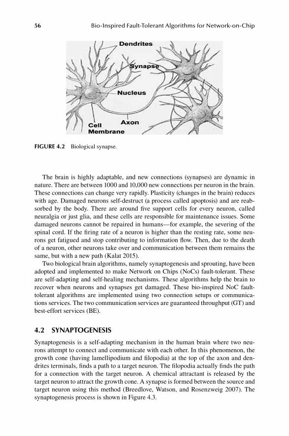
56 Bio-Inspired Fault-Tolerant Algorithms for Network-on-Chip
The brain is highly adaptable, and new connections (synapses) are dynamic in nature. There are between 1000 and 10,000 new connections per neuron in the brain. These connections can change very rapidly. Plasticity (changes in the brain) reduces with age. Damaged neurons self-destruct (a process called apoptosis) and are reab-sorbed by the body. There are around five support cells for every neuron, called neuralgia or just glia, and these cells are responsible for maintenance issues. Some damaged neurons cannot be repaired in humans—for example, the severing of the spinal cord. If the firing rate of a neuron is higher than the resting rate, some neu-rons get fatigued and stop contributing to information flow. Then, due to the death of a neuron, other neurons take over and communication between them remains the same, but with a new path (Kalat 2015).
Two biological brain algorithms, namely synaptogenesis and sprouting, have been adopted and implemented to make Network on Chips (NoCs) fault-tolerant. These are self-adapting and self-healing mechanisms. These algorithms help the brain to recover when neurons and synapses get damaged. These bio-inspired NoC fault-tolerant algorithms are implemented using two connection setups or communica-tions services. The two communication services are guaranteed throughput (GT) and best-effort services (BE).
4.2 SYNAPTOGENESIS
Synaptogenesis is a self-adapting mechanism in the human brain where two neu-rons attempt to connect and communicate with each other. In this phenomenon, the growth cone (having lamellipodium and filopodia) at the top of the axon and den-drites terminals, finds a path to a target neuron. The filopodia actually finds the path for a connection with the target neuron. A chemical attractant is released by the target neuron to attract the growth cone. A synapse is formed between the source and target neuron using this method (Breedlove, Watson, and Rosenzweig 2007). The synaptogenesis process is shown in Figure 4.3.
FIGURE 4.2 Biological synapse.
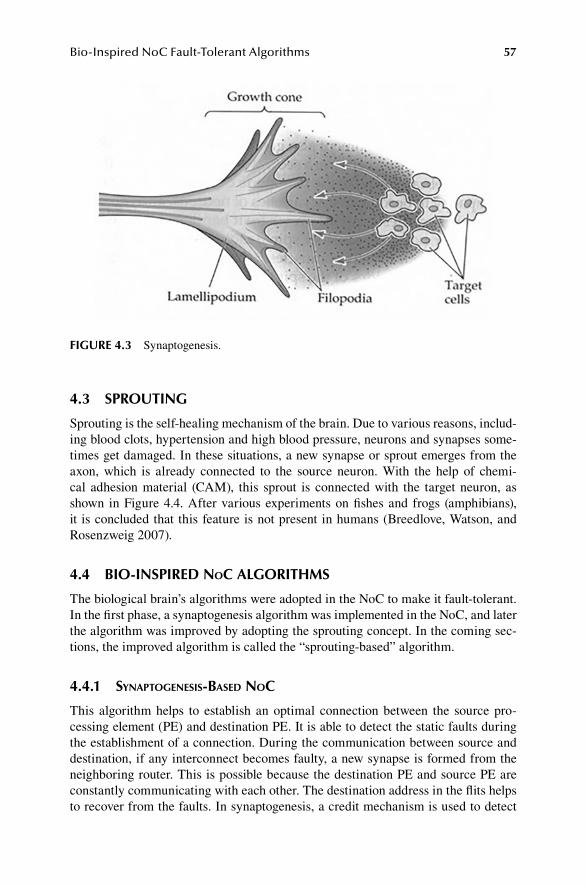
57Bio-Inspired NoC Fault-Tolerant Algorithms
4.3 SPROUTING
Sprouting is the self-healing mechanism of the brain. Due to various reasons, includ-ing blood clots, hypertension and high blood pressure, neurons and synapses some-times get damaged. In these situations, a new synapse or sprout emerges from the axon, which is already connected to the source neuron. With the help of chemi-cal adhesion material (CAM), this sprout is connected with the target neuron, as shown in Figure 4.4. After various experiments on fishes and frogs (amphibians), it is concluded that this feature is not present in humans (Breedlove, Watson, and Rosenzweig 2007).
4.4 BIO-INSPIRED noC ALGORITHMS
The biological brain’s algorithms were adopted in the NoC to make it fault-tolerant. In the first phase, a synaptogenesis algorithm was implemented in the NoC, and later the algorithm was improved by adopting the sprouting concept. In the coming sec-tions, the improved algorithm is called the “sprouting-based” algorithm.
4.4.1 SynaPtogeneSiS-BaSeD noC
This algorithm helps to establish an optimal connection between the source pro-cessing element (PE) and destination PE. It is able to detect the static faults during the establishment of a connection. During the communication between source and destination, if any interconnect becomes faulty, a new synapse is formed from the neighboring router. This is possible because the destination PE and source PE are constantly communicating with each other. The destination address in the flits helps to recover from the faults. In synaptogenesis, a credit mechanism is used to detect
FIGURE 4.3 Synaptogenesis.

58 Bio-Inspired Fault-Tolerant Algorithms for Network-on-Chip
the fault in the NoC. It takes 3 ns to detect the fault, as the router does not receive the credit packet from the neighboring router. In order to improve fault detection and performance of the NoC, a sprouting algorithm was proposed.
4.4.2 SProuting-BaSeD noC
With the help of the sprouting algorithm, a synapse (sprout) emerged from the syn-apse already connected with the source PE when an interconnect became faulty during the communication. This algorithm detects the run-time faults during the communication and creates a workaround synapse (connection) to bypass the faulty interconnects. The sprouting algorithm detects the faults as the flits arrive at the block port of a particular router. The port is blocked when a fault occurs in the
FIGURE 4.4 Sprout.

59Bio-Inspired NoC Fault-Tolerant Algorithms
interconnect. No credit packet is required in the sprouting algorithm to detect the fault, avoiding the waste of 3 ns, as in the case of synaptogenesis. This helps the algorithm to quickly create a workaround synapse compared to synaptogenesis. The sprout emerges as the destination address is saved in every flit. Therefore, the overall performance of the sprouting algorithm is better compared to the synaptogenesis algorithm.
The algorithms recover from the static and run-time faulty interconnects by creat-ing a workaround synapse. Multiple synapses are formed between the source PE and destination PE, which efficiently utilizes the bandwidth, maximizes the throughput and recovers from the faults quickly.
4.5 BIO-INSPIRED noC FRAMEWORK
Initially, the synapse is initiated from the source PE toward the destination PE. The synapse is routed on the NoC using two-hop information and arrives at the destina-tion. The destination in return sends the route reply packet. After receiving the route reply packet at the source PE, the flits are sent from the source PE to the destination PE. If no fault is detected during the communication, then flits reach the destination. Otherwise, the neighbor router detects the fault and initiates the synapse connection (sprout) between the current router and either the older synapse or the destination router. If there is no older synapse to connect with, the sprout is directly connected with the destination PE.
Whenever a fault occurs, the destination address, routing path and routers tra-versed are saved in the new synapse. These parameters help the newer synapse con-nect with the older synapse. The bio-inspired algorithm is robust, as it tries to connect with the older synapse and also avoids the traversal of unnecessary routers. This also decreases the latency of the packets/flits even when faults occur. The bandwidth of the NoC is also efficiently utilized, and throughput is slightly decreased for a short period of time as the NoC recovers from the faulty interconnect. During the network recovery time, the destination is still receiving the flits from other synapses. These flits have already traversed the faulty interconnect. The generalized framework of the bio-inspired algorithm is shown in Figure 4.5.
In bio-inspired algorithms, the “Scheduler” module of the port plays a significant role in fault detection. The port is a fundamental building block of the router. The routers are connected with each other through interconnects in an NoC network.
4.6 BIO-INSPIRED noC NETWORK
In the bio-inspired NoC, routers are connected with each other through bidirectional links. Each PE is connected with the router through a network interface. There are five ports in the router. Four ports are connected with the neighbor routers, that is, north, east, west and south, while the fifth port is connected with the PE. Every port has an “inPort”, which receives packets from the neighbor router or from the PE. The “OutPortCalc” is used to calculate the optimum output port for “synap” packets. The output port is determined based on the destination and faulty situation of neighbor router, collected with the help of control packets. The “Scheduler” is used to control

60 Bio-Inspired Fault-Tolerant Algorithms for Network-on-Chip
FIGURE 4.5 Bio-inspired NoC algorithm process flow.
the output port (Ben-Itzhak et al. 2012), as shown in Figure 4.6. The “Scheduler” sends the packet at the (Out) link when the interconnect is free. The “Scheduler” is connected with the “inPort” for disseminating the fault detection information and data flits to the “inPort” of that particular port. Later, these data flits are sent on the new workaround synapse initiated by “inPort”.

61Bio-Inspired NoC Fault-Tolerant Algorithms
The detailed architecture of the port is shown in Figure 4.7. The “SW_in”, “SW_out”, “SW_Ctrl_in”, “SW_Ctrl_out” and “Ctrl” pins are used to control the flow of data flits between routers. “SW_in” and “SW_out” are unidirectional lines, whereas “SW_Ctrl_in” and “SW_Ctrl_out” are bidirectional lines. Control packets of grant, request, response and nack are shared through the “SW_Ctrl_in” and “SW_Ctrl_out” pins between the ports of a particular router. Similarly, “SW_in” and “SW_out” pins are used to send data flits between various ports of the router.
The “out” pins of the “inPort” are connected to the “SW_in” pins of the port, while “Ctrl” pins are connected with the “SW_Ctrl_in” pins. The “in” pins of the “Scheduler” are connected with “SW_out” pins, while “Ctrl” pins are connected with “SW_Ctrl_out” pins, as shown in Figure 4.8. Each “SW_in” pin is connected with every port in the router. Similarly, “SW_out” pins of the particular port are connected with every other port in the router. The “SW_Ctrl_in” pins in the router
FIGURE 4.6 Port architecture.
FIGURE 4.7 Detailed port architecture.

62 Bio-Inspired Fault-Tolerant Algorithms for Network-on-Chip
are connected with every other port in the router through “SW_Ctrl_out”. Similarly, “SW_Ctrl_out” pins are connected with “SW_Ctrl_in” pins of every other port on the particular router.
Each of the five ports in a router are connected with each other through cross-bar interconnections. Every port is connected with every other port in the router, as shown in Figure 4.9 and Figure 4.10. The “SW_in”, “SW_out”, “SW_Ctrl_in” and “SW_Ctrl_out” are connected together between different ports of the router. In Figure 4.9, four pins of “SW_out” of port 0 (north) are connected with the one “SW_in” pin of port 1 (west), port 2 (south), port 3 (east) and port 4 (local core), respec-tively. Similarly, four pins of “SW_Ctrl_out” of port 0 are connected with the each “SW_Ctrl_in” of ports 1, 2, 3, and 4 respectively, as shown in Figure 4.10. The same mechanism is used for other ports of a router. The data flits traverse from “SW_in” of one router port to “SW_out” of the other port of the same router, whereas control packets traverse on the “SW_Ctrl_in” and “SW_Ctrl_out” (Ben-Itzhak et al. 2012).
4.7 BIO-INSPIRED noC FAULT-TOLERANT ALGORITHM
In the NoC, routers discover themselves at system initialization. The network discov-ery is initiated by the “Scheduler” of the router port. The Scheduler sends the request packet to the neighbor router, which in return, replies with a response control packet. The response packet is sent by the “inPort” module of the particular router port. After sharing the control packets, routers know about the status of their neighbor routers, that is, either they are working or not working. If after 1 ns the response is
FIGURE 4.8 Detailed port architecture connections.

63Bio-Inspired NoC Fault-Tolerant Algorithms
FIGURE 4.9 Router port connections for data paths (SW_in with SW_out).
FIGURE 4.10 Router port connections for control paths (SW_Ctrl_in with SW_Ctrl_out).

64 Bio-Inspired Fault-Tolerant Algorithms for Network-on-Chip
not received at the “Scheduler” port of the sending router, then that port is blocked, as either the interconnect or neighbor router is faulty. The bio-inspired NoC algo-rithm only needs one network discovery at initialization. This efficiently utilizes the bandwidth of the NoC and improves overall performance.
After network discovery, the source PE initiates the synapse “synap” packet to connect with the destination PE. When a router receives the “synap” packet, it sends information set (IS) request packets to its neighbors through the “Scheduler”. Neighbor routers reply to this request with IS response packets containing its information (direction neighbor, DN) and its immediate neighbors (IN) informa-tion through the “inPort”. The immediate neighbors for an ISW (west) packet are east, north and south, while west, north and south are the INs of ISE (east) packets. Similarly, north, east and west are the immediate neighbors of ISS (south) packets, while ISNs (north) have the INs of the south, east and west. The neighbor router sends back the information in the ISW, ISE, ISS and ISN response packets, as shown in Figure 4.11. The information in the IS response packet is 1 (working), 0 (not work-ing) and –1 (neighbor does not exist). The flow of the IS request and response packets
FIGURE 4.11 IS response packet format.

65Bio-Inspired NoC Fault-Tolerant Algorithms
is shown in Figure 4.12 and Figure 4.13 with router id=10 as an example (Nicopoulos, Narayanan, and Das 2009).
Upon receiving all the IS packets from the neighbors, the router prioritizes the path based on the information present in the IS packets and the location of the desti-nation, as shown in Figure 4.14. For example, if the destination (PE connected with router 16) is toward the east, depending on the faulty situation of the neighbors, the first priority to send the packet is toward the east, the second priority is toward the south, the third priority is toward the north and the last option is to send the packet toward the west.
If DN is zero (not working), then that path is blocked immediately. If the DN is 1 (working) and all three INs are faulty, the path is still blocked, as the “synap” will not be able to pass through the neighbor routers. If the DN is 1 and any one of the INs is working (1), the “synap” packet is sent in that particular direction. This algorithm can be further optimized by controlling the flow of the packet; the “synap” packets should be sent in specific directions where more INs are working, rather than in one direction only.
The following are the five broad cases that may occur based on the information received and processed by the router (outPortCalc) using the information present in ISW, ISE, ISS and ISN packets and based on the location of the destination.
FIGURE 4.12 IS request packet flow.

66 Bio-Inspired Fault-Tolerant Algorithms for Network-on-Chip
Router(id=3)
PE
NI
Router(id=4)
PE
NI
Router (id=1)
PE
NI
Router (id=2)
PE
NI
Router (id=7)
Router(id=8)
PE
NI
Router(id=5)
PE
NI
Router(id=6)
Router(id=11)
Router (id=12)
PE
NI
Router(id=9)
PE
NI
Router(id=10)
Router (id=15)
PE
NI
Router (id=16)
PE
NI
Router(id=13)
PE
NI
Router(id=14)
PE
NI
ISE ISW
ISN
ISS
FIGURE 4.13 IS response packets.
FIGURE 4.14 Priorities of “synap” packet.

67Bio-Inspired NoC Fault-Tolerant Algorithms
CASE 1: DESTINATION IS TOWARD THE EAST
If the destination is toward the east, then the first priority is to send the “synap” packet in this direction. If the east interconnect is faulty, then the next priority will be to send the flit toward the north. If the north interconnect is faulty, then the next priority is to send the “synap” packet toward the south. The last priority will be to send the “synap” packet toward the west, which is opposite from the destination. If all ports are faulty, then the “synap” packet has to wait.
CASE 2: DESTINATION IS TOWARD THE WEST
If the destination is toward the west, then the first priority is to send the “synap” packet in this direction. If the west interconnect is faulty, then the next priority will be to send the flit toward the north. If the north interconnect is faulty, then the next priority is to send the “synap” packet toward the south. The last priority will be to send the “synap” packet toward the east, which is opposite from the destination. If all ports are faulty, then the “synap” packet has to wait.
CASE 3: DESTINATION IS TOWARD THE NORTH
If the destination is toward the north, then the first priority is to send the “synap” packet in that direction. If the north interconnect is faulty, then the next priority will be to send the flit toward the east. If the east interconnect is faulty, then the next pri-ority is to send the “synap” packet toward the west. The last priority will be to send the “synap” packet toward the south, which is opposite from the destination. If all ports are faulty, then the “synap” packet has to wait.
CASE 4: DESTINATION IS TOWARD THE SOUTH
If the destination is toward the south, then the first priority is to send the “synap” packet in that direction. If the south interconnect is faulty, then the next priority will be to send the flit toward the east. If the east interconnect is faulty, then the next pri-ority is to send the “synap” packet toward the west. The last priority will be to send the “synap” packet toward the north, which is opposite from the destination. If all ports are faulty, then the “synap” packet has to wait.
CASE 5: LOCAL CORE (PE)
If the current router’s x-axis (rx) and y-axis (ry) are equal to the target router’s (des-tination PE) x-axis (dx) and y-axis (dy), then the “synap” packet is send toward the local core (PE).
Figure 4.15 shows the x-axis and y-axis values of routers in a 4 × 4 NoC. The router (0) has rx=0 and ry=0 values, whereas router (15) has rx=3 and ry=3 values. The dx and dy values also depend on the coordinate values of the routers. For exam-ple, if the destination is at the router (10), then the value of dx and dy will be 2. The details regarding different possibilities of the routing algorithm when the destination is toward the east, west, south and north are shown in Figure 4.16 to Figure 4.19,

68 Bio-Inspired Fault-Tolerant Algorithms for Network-on-Chip
respectively. In these figures, dy, dx specify the destination address in the form of coordinates, while rx, ry specifies the current router location in the NoC using x-axis and y-axis values.
It can be seen in Figure 4.16 that the routing algorithm depends on the values of dx, dy, rx and ry. If dx>rx, then the destination is toward east. The first priority is to send the “synap” packet in this direction, but if the east port is blocked due to a faulty interconnect, then the second priority depends on the location of the destina-tion. If the destination is toward the south or at the same column of the NoC (dy>ry || dy==ry), then the “synap” packet is traversed toward the south first and later toward the north if the route toward the south is faulty. Or if the destination is toward the north (dy<ry), then the first priority will be to send the packet toward the north and later to the south if the north path is faulty. The last priority will be to send the packet toward the west, which is opposite from the destination. If all ports are faulty, then the “synap” packet has to wait.
Figure 4.17 shows that if dx<rx, then the destination is toward the west. The first priority is to send the “synap” packet in this direction, but if the west port is blocked due to a faulty interconnect, then the second priority depends on the location of the
FIGURE 4.15 The rx and ry values of routers in 4 × 4 NoC.

69Bio-Inspired NoC Fault-Tolerant Algorithms
FIGURE 4.16 Process flow when the destination is toward the east, with various possibilities.
FIGURE 4.17 Process flow when the destination is toward the west, with various possibilities.
destination. If the destination is toward the south or at the same column (dy>ry || dy==ry), then the “synap” packet is traversed toward the south first and later toward the north if the route toward the south is faulty. Or if the destination is toward the north (dy<ry), then the first priority will be to send the packet toward the north and later to south if the north path is faulty. The last priority will be to send the packet toward the east, which is opposite from the destination. If all ports are faulty, then the “synap” packet has to wait.
As shown in Figure 4.18, if dy>ry, then the destination is toward the south. The first priority is to send the “synap” packet in this direction, but if the south port is

70 Bio-Inspired Fault-Tolerant Algorithms for Network-on-Chip
blocked due to a faulty interconnect, then the second priority depends on the location of the destination. If the destination is toward the east or at the same row (dx>rx || dx==rx), then the “synap” packet is traversed toward the east first and later toward the west if the route toward the east is faulty. Or if the destination is toward the west (dx<rx), then the first priority will be to send the packet toward the west and later to the east if the west path is faulty. The last priority will be to send the packet toward the north, which is opposite from the destination. If all ports are faulty, then the “synap” packet has to wait.
As shown in Figure 4.19, if dy<ry, then the destination is toward the north. The first priority is to send the “synap” packet in this direction, but if the north port is
FIGURE 4.18 Process flow when the destination is toward the south, with various possibilities.
FIGURE 4.19 Process flow when the destination is toward the north, with various possibilities.

71Bio-Inspired NoC Fault-Tolerant Algorithms
blocked due to a faulty interconnect, then the second priority depends on the location of the destination. If the destination is toward the east or at the same row (dx>rx || dx==rx), then the “synap” packet is traversed toward the east first and later toward the west if the east path is faulty. Or if the destination is toward the west (dx<rx), then the first priority will be to send the packet toward the west and later to the east if the west path is faulty. The last priority will be to send the packet toward the south, which is opposite from the destination. If all ports are faulty, then the “synap” packet has to wait.
After the establishment of a synapse between the source PE and destination PE, data flits are sent from the source to the destination over the path specified by the “synap” packet. The path is saved in every flit to address fault tolerance. If there is no faulty interconnect along the way, then the data flits will traverse the path. If dur-ing the communication an interconnect becomes faulty, a neighbor router detects the fault through the “Scheduler”. A new sprout (synapse) emerges from the neighbor router “inPort” to bypass the faulty interconnect. The port of the router connected with that particular faulty interconnect is blocked through the “Scheduler” and the “sourceInform” packet is sent to “inPort”. The “sourceInform” is used to inform and initiate a new workaround synapse from the current router to bypass the faulty interconnect or router, as shown in Figure 4.20.
FIGURE 4.20 Source inform code.
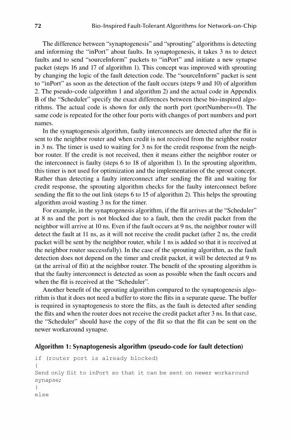
72 Bio-Inspired Fault-Tolerant Algorithms for Network-on-Chip
The difference between “synaptogenesis” and “sprouting” algorithms is detecting and informing the “inPort” about faults. In synaptogenesis, it takes 3 ns to detect faults and to send “sourceInform” packets to “inPort” and initiate a new synapse packet (steps 16 and 17 of algorithm 1). This concept was improved with sprouting by changing the logic of the fault detection code. The “sourceInform” packet is sent to “inPort” as soon as the detection of the fault occurs (steps 9 and 10) of algorithm 2. The pseudo-code (algorithm 1 and algorithm 2) and the actual code in Appendix B of the “Scheduler” specify the exact differences between these bio-inspired algo-rithms. The actual code is shown for only the north port (portNumber==0). The same code is repeated for the other four ports with changes of port numbers and port names.
In the synaptogenesis algorithm, faulty interconnects are detected after the flit is sent to the neighbor router and when credit is not received from the neighbor router in 3 ns. The timer is used to waiting for 3 ns for the credit response from the neigh-bor router. If the credit is not received, then it means either the neighbor router or the interconnect is faulty (steps 6 to 18 of algorithm 1). In the sprouting algorithm, this timer is not used for optimization and the implementation of the sprout concept. Rather than detecting a faulty interconnect after sending the flit and waiting for credit response, the sprouting algorithm checks for the faulty interconnect before sending the flit to the out link (steps 6 to 15 of algorithm 2). This helps the sprouting algorithm avoid wasting 3 ns for the timer.
For example, in the synaptogenesis algorithm, if the flit arrives at the “Scheduler” at 8 ns and the port is not blocked due to a fault, then the credit packet from the neighbor will arrive at 10 ns. Even if the fault occurs at 9 ns, the neighbor router will detect the fault at 11 ns, as it will not receive the credit packet (after 2 ns, the credit packet will be sent by the neighbor router, while 1 ns is added so that it is received at the neighbor router successfully). In the case of the sprouting algorithm, as the fault detection does not depend on the timer and credit packet, it will be detected at 9 ns (at the arrival of flit) at the neighbor router. The benefit of the sprouting algorithm is that the faulty interconnect is detected as soon as possible when the fault occurs and when the flit is received at the “Scheduler”.
Another benefit of the sprouting algorithm compared to the synaptogenesis algo-rithm is that it does not need a buffer to store the flits in a separate queue. The buffer is required in synaptogenesis to store the flits, as the fault is detected after sending the flits and when the router does not receive the credit packet after 3 ns. In that case, the “Scheduler” should have the copy of the flit so that the flit can be sent on the newer workaround synapse.
Algorithm 1: Synaptogenesis algorithm (pseudo-code for fault detection)
if (router port is already blocked){Send only flit to inPort so that it can be sent on newer workaround synapse;}else

73Bio-Inspired NoC Fault-Tolerant Algorithms
{Send flit on (Out) link of “Scheduler” to neighbor router;Wait for 3 ns for credit packet; \\timerif (credit received){Cancel timer;Increment credit at “Scheduler”;}else{Fault detected;Inform inPort to initiate newer workaround synapse to bypass fault; \\sourceInform packet}}
Algorithm 2: Sprouting algorithm (pseudo-code for fault detection)
if (router port is already blocked){Send only flit to inPort so that it can be sent on newer workaround synapse;}else{if (this port is blocked){Fault detected;Inform inPort to initiate newer workaround synapse to bypass fault; \\sourceInform packet}else{Send flit on (Out) link of “Scheduler” to neighbor router;}}
Algorithm 3 is the pseudo-code of the overall bio-inspired algorithm. This algorithm only specifies one case when the destination is toward the east. Initially, a synapse connection is established between the source PE and destination PE (steps 1 to 14). The “synap” packet is initiated from the source PE, and it traverses through the routers by having two-hop neighbors’ information (steps 1 to 13). Once the synapse (connection) is established between the source PE and destination PE, flits traverse over this synapse (steps 14 and 15). If during the communication, the interconnect becomes faulty, then the neighbor router detects the fault and initiates the work-around synapse (sprout) connection (steps 16 to 18). During establishment of the new workaround synapse, the “synap” packet always tries to connect with the older synapse. If an older synapse connection does not exist, then the “synap” packet is

74 Bio-Inspired Fault-Tolerant Algorithms for Network-on-Chip
connected directly with the destination PE. After the workaround synapse connec-tion is established, data flits move over it (steps 19 and 20).
Algorithm 3: Bio-inspired algorithm (when the destination is toward the east)
“Synap” packet initiated from source to destination.if (“Synap” reached at Destination)Send the “Synap” packet to destination coreElse if (Destination toward East)check East DN and INs conditionElse if //East DN or INs Faultycheck North DN and INs conditionElse if //North DN or INs FaultyCheck South DN and INs conditionElse if //South DN or INs FaultyCheck West DN and INs ConditionElse if //if all neighbor ports of router are faulty“Synap” packet has to waitSend the “Synap” packet to selected directionSynapse connection is formed between source and destination.Data flits move from source to destination over the synapse.Upon interconnect failure neighbor router detects the fault.The flits are saved in the “Scheduler” and later at the “inPort” module of the router.Router initiates a synap connection (sprout) and tries to connect the new synapse with the older synapse.If older synapse does not exist then the new synapse directly connects with the destination.Data flits are sent from the workaround newer synapse.
Figure 4.21 shows the implementation of the bio-inspired algorithm when intercon-nect failure occurs. The synapse was constructed from the source (0) to destination (15) at the start of the communication between them. During the simulation, the links between various routers became faulty and a workaround synapse was initi-ated to bypass the faulty interconnects. The temporary synapse was formed between router (1) and router (7) to bypass the faulty interconnect between router (1) and router (2). As shown in the figure, the workaround synapse is bypassing router 2 and router 3 and connecting directly with the old synapse at router 7. The same mecha-nism is adopted for any number of faults in the NoC. The crosses in the figure show the faulty interconnects.
4.8 BIO-INSPIRED BE AND GT noC ALGORITHM AND ARCHITECTURES
The bio-inspired NoC algorithms are implemented using BE and GT and combined BE-GT services. In both service levels, a 4 × 4 NoC mesh topology is used. The rout-ers are connected with each other, while the PEs are connected with routers through the network interface (NI). The overall port architecture of routers in both NoCs is

75Bio-Inspired NoC Fault-Tolerant Algorithms
the same except the architecture of the “Scheduler”, “inPort” and some control/data pins. These control and data pins are used in the BE and GT architecture to control the flow of flits between routers. In the GT architecture, there are time slots at the “Scheduler” and multiple queues at the “inPort”. However, in the BE architecture, there is a credit-based flow control technique to manage the communication between routers.
4.8.1 Be ServiCeS in the noC arChiteCture
The port architecture of the BE router is similar to Figure 4.6. In BE services, no resources (routers, interconnects) are reserved. Any source can send the packet based on the availability of an output port. The decision to send the packet in a particular direction is made on a router-to-router basis based on the destination address. The “Scheduler” detects the faults, and later it transfer flits to the “inPort” to save these flits. The “inPort” contains the buffers to store these flits.
In BE services, credit-based flow control (Hansson, Goossens, and Rădulescu 2007) is used to control the flow of flits between routers and PEs. In this mechanism, the “Scheduler” looks at the credit counter before sending the flit to the output port. If the credit is more than zero, then it can send the flits at that particular port; a zero credit means the port is busy and waiting for feedback (credit) from a neighbor. The
FIGURE 4.21 Multiple connections between source and destination.

76 Bio-Inspired Fault-Tolerant Algorithms for Network-on-Chip
exchange of credit information protects the links from congestion and collision and avoids the deadlock situation.
After receiving a flit at the “inPort”, the credit packet is sent back to the “Scheduler” to increment the virtual channel credit counter. The credit counter is incremented by one, as only one flit is sent by the Scheduler per clock cycle. Currently, two virtual channels are supported between routers to send flits on.
The code shown in Figure 4.22 is used to send the credit packet from “inPort” to the neighbor router “Scheduler”. crd is the credit object created at the “inPort”. The credit is incremented for a specific virtual channel (vc) by a number of flits (num-Flits) at the “Scheduler”. The “inPort” specifies the (vc) and (numFlits) parameters.
At the receiver side, this credit packet is received at the “Scheduler”, and the credit counter is incremented by one, as specified by the number of flits (“numFlits”) variable, as shown in Figure 4.23.
The flow of control and data packets is shown in Figure 4.24. The “synap” packet is initiated by the source PE to connect and start communication with the destina-tion PE.
In BE services, before sending the flits to the next router, the particular port of a router sends a “request” packet to the port. The request packet specifies the target port that the particular port wants to send flits to. If the credit counter is greater than one and the port is not busy, then the target port will send the grant packet to the port. Then, the port will send the flits to the target port. If the port is busy or the credit counter is zero, then the target port will not send an acknowledge packet, and the port has to send the request again to the target port. Once the router sends a flit to the neighbor router, the credit counter is decremented, and the port status becomes busy until it receives the acknowledgment in the form of a credit packet from the neighbor router. If the router does not receive the credit by a specific time (3 ns), then
FIGURE 4.23 Code for incrementing credit counter at “Scheduler”.
FIGURE 4.22 Code for sending credit packet from inPort.

77Bio-Inspired NoC Fault-Tolerant Algorithms
the router will assume that a fault has occurred in the neighbor and will initiate a workaround synapse packet to bypass the fault.
In the BE routing algorithm of the NoC architecture, before making any decision regarding the direction of the “synap” packet, the information in the ISs is processed. The router makes sure that the direct neighbor is not faulty and that at least one IN is working. The code in Figure 4.25 explains the concept.
In this code, the destination is assumed to be toward the east. The same concept and logic are used for making decisions regarding the other directions. DNW is the variable that specifies the processed information of the ISW packet. The values are in the range of 0, 1, 2 and 3. Zero specifies that the DN and all INs are working.
Synap
Synap
Route Reply
Route Reply
Data Flits
Data FlitsNode by Node
Acknowledgment (through credit
messages)
Source PEImmediate
Routers Destination PE
Node by Node Acknowledgment
Routers send IS signals to neighbors and receive reply in the form of ISW, ISE, ISN, ISS. Based on this information prioritizes
the route.
FIGURE 4.24 Timing diagram of packet flow between source PE and destination PE using BE.

78 Bio-Inspired Fault-Tolerant Algorithms for Network-on-Chip
DN values are calculated by summing up the “0” (not working status) and “–1” (neighbor does not exist) in IS packets. A 1 specifies that either the IN or DN is not working. Similarly, 2 and 3 specify the faulty interconnects in the neighbors of the current router. For DNW to equal 0, there are three different cases to check before making any decision. If the DN is 0 (faulty) (that is, the DN should not be equal to 0, isWest[srcId][0]!=0), then this path is not selected. For the other three cases, all the INs are checked (isWest[srcId][i]==1). If any one of the INs is working, then that path is selected. It is possible that the east port is already blocked due to a faulty intercon-nect, and it should be checked (eastPort!=-1).
Similarly, the same code is used for every NoC direction and for every value of DNW, DNS, DNE and DNN. The values of DNW, DNE, DNS and DNN range from 0 to 3. If the DNW, DNE, DNS and DNN value is 4, it means that the DN and all INs are not working (0) or the neighbor does not exist (–1). That NoC direction is totally avoided in that case. The code shown in Figure 4.26 is used to activate the particular interconnect during the simulation. The code is used to bring the particular intercon-nect back to a working condition by activating its ports.
The NoCRouterAliveMsg object is used to reactivate a particular port. The inter-connects are connected with these ports. The curRouter object refers to the current router whose ports need activation. portNumber refers to the current port that needs activation, and curRouter->par(“northPort_W”)= 1, will activate the northPort back to working condition. The same logic is used for the other ports. Figure 4.27 shows
FIGURE 4.25 Code to process information in ISs.

79Bio-Inspired NoC Fault-Tolerant Algorithms
the flow of packets when a router port becomes busy. During the transmission of packets, two sources want to communicate through one port; thus, one source has to wait to acquire the port. As can be seen in the figure, when source 2 sends a request packet to acquire the port, which is already acquired by source 1, source 2 will receive the “Port Busy” packet from the router through the “Ctrl” port and then it will wait for the “Port Free” packet before sending the packets through the “Ctrl” ports of the particular port of the router.
4.8.2 gt ServiCeS in the noC arChiteCture
The port architecture of the GT is similar to Figure 4.6. The difference is between the architecture of the “inPort” and “Scheduler”. Each “inPort” has a separate queue for every virtual channel. This avoids head of line (HOL) blocking whenever faults occur. The Scheduler has four time slots, which are allocated at run time to vari-ous virtual channels. The optimum four slots are reserved based on the literature (Hansson, Subburaman, and Goossens 2009). The time slots are managed and read by the time division multiplexing (TDM) clock. The TDM clock is running autono-mously at every router, and the clock period is 2 ns. The time slots help to efficiently utilize and divide the bandwidth of the NoC among the four connections.
Different slots are allocated to four virtual channels: A, B, C and D. The routers (R) increment the slot number by 1, as stated in Equation (4.1). At every time slot, the router is sending one packet to the (Out) link from any virtual channel. This is
FIGURE 4.26 Code to activate the ports.

80 Bio-Inspired Fault-Tolerant Algorithms for Network-on-Chip
Synap
Synap
Route Reply
Route Reply
Data Flits
Data FlitsNode by Node
Acknowledgment
Source(s)Immediate
Routers Destination
Particular port of router becomes busy
Source 1 send data flits
Data Flits
Source 2 wants to send data flits on the
busy port of router
Router Port Busy
When source 1 finishes sending data
Router Port Free
Source 2 sends data flits Data Flits
FIGURE 4.27 Timing diagram for the flow of packets between source and destination when router port is busy.

81Bio-Inspired NoC Fault-Tolerant Algorithms
contention-free routing, as there is no collision between packets from different vir-tual channels. The TDM concept is shown in Figure 4.28.
slotAllocated previousAllocatedSlot� � � �1 4) (4.1)
Contention-free routing is achieved with the help of different time slots. In contention-free routing, there is no collision between packets of multiple connections to access one output port. With the help of time slots, time to access the (Out) link is divided between multiple virtual channels. Every virtual channel equally shares the bandwidth of the (Out) link. The slots are allocated by the Scheduler of the router. Every router in the NoC increments one slot from the previous slot number, as shown in Figure 4.29. In the figure, slot 2 is dedicated to virtual channel B, while in the next router, the slot is incremented by 1 and slot 3 is assigned to virtual channel B. This helps to efficiently utilize the band-width, and one flit is routed from four routers in the consecutive four clock cycles. The “Scheduler” skips those slots that are not allocated to any of the virtual channels. This helps the connection to efficiently utilize the bandwidth of the interconnect and maintain the high throughput for that particular connection. The skipping of the unallocated time slots also increases the performance of a specific port, as it will dedicate the available bandwidth to already allocated active connections (Rijpkema et al. 2003).
If the bandwidth of the (Out) link physical channel is (bw) and there are (vc) vir-tual channels transmitting the flits (data), each virtual channel will have a throughput of THmin (Gbps), as in Equation (4.2) (Kavaldjiev et al. 2006).
THmin =bw
vc(4.2)
FIGURE 4.28 TDM mechanism for contention-free routing.

82 Bio-Inspired Fault-Tolerant Algorithms for Network-on-Chip
The bio-inspired NoC currently has four slots per port. So, there can be four virtual channels per port. The algorithm allocates the slots to the “Scheduler” so the through-put (THmin) is guaranteed to each and every virtual channel (Kavaldjiev et al. 2006).
The Scheduler architecture of a router is shown in Figure 4.30. The slots are reserved during synapse establishment in the “OutPortCalc” module. Before decid-ing on any direction for the “synap” packet, the “OutPortCalc” checks whether any slot is available for this port. If yes, it will allocate the slot to the virtual connection;
FIGURE 4.29 Router delays time slot allocation by one slot during connection setup.
FIGURE 4.30 Scheduler architecture of a router with a slot table.

83Bio-Inspired NoC Fault-Tolerant Algorithms
otherwise, the “synap” is directed to another port based on the information present in the ISs. As shown, there are four virtual channels accessed by one router. The slot table is used to keep track of the slots allocated to each virtual channel.
The code in Figure 4.31 shows the allocation and checking of slots for “core-Port”. If a time slot is available, only then can a virtual connection be established with “corePort”. The slots are checked for all the cases mentioned in Figure 4.16, Figure 4.17, Figure 4.18 and Figure 4.19 before deciding on the direction of the “synap” packet. If (accessSlot==-1), then the slot (slotIndex) is not allocated to any connection. A total number of slots (numberOfSlot) at “Scheduler” are four.
There are four virtual channels (A, B, C, D), which are allocated to slots A, B, C and D. The timer variable synchronizes every slot at the “Scheduler”. The “Scheduler” sends the packets (reqTDM) to read data from that port for a particular virtual chan-nel. This helps with multiplexing and avoids contention between multiple connections.
In the code shown in Figure 4.32, the “Scheduler” is sending a “reqTDM” packet to a particular port to read a particular queue allocated to a certain slot (slotRead) and port (portIndex). This packet is sent on the “ctrl” port of the “Scheduler”, as this is a control packet. In reply to this packet, “inPort” reads a particular queue allocated to this slot and sends the flit to a particular “Scheduler” of a port.
For every virtual channel, a separate queue is allocated at the “inPort” of the router, as shown in Figure 4.33. This helps avoid the HOL blocking problem when a fault occurs.
When the “inPort” reads a packet from the “Scheduler” to send the data, a par-ticular queue is read from the “inPort”, which is allocated to that slot. The “queue to read” parameter is provided by the “Scheduler”. With the help of the TDM-based router, there is no collision between packets or deadlock scenario, as the “Scheduler”
FIGURE 4.31 Code for allocation and checking of slots.
FIGURE 4.32 Code for sending reqTDM packet at “Scheduler”.

84 Bio-Inspired Fault-Tolerant Algorithms for Network-on-Chip
only allows one flit per router during one clock cycle. The code shown in Figure 4.34 specifies that “inPort” is receiving a request from “Scheduler” to read a particular queue. The “tdmRequestFromPort” and “tdmSlotFromPort” information is pro-vided by the “Scheduler” when a particular slot is read. Later, the queue allocated to the particular slot is read. The flit that is saved in the queue is read and sent to the output port of the “inPort”. This flit is received at the particular “Scheduler” of the port and “Scheduler” will send it to the (Out) link.
The flow of the packets in the bio-inspired NoC using the GT architecture is shown in Figure 4.35. The flow of packets is similar to the BE architecture except the use of a slot table at “Scheduler” and “Queues” at the “inPort”. At every clock cycle, the slot is read at the “Scheduler”. The “Scheduler” sends the “Request to send” packet to the port allocated in the slot. This packet is used to read a particular queue at the “inPort”, which is allocated to this slot using a virtual channel. The communi-cation between the source and destination proceeds like this until the end flit is sent by the source to terminate this connection.
4.8.3 ComBineD Be-gt ServiCeS in the noC arChiteCture
To efficiently utilize the bandwidth of the NoC, BE services are provided along with GT services (Rijpkema et al. 2003). Figure 4.36 shows the combined BE-GT router port architecture. The packets with flits are received at the inPort, where the packet is saved either in the BE or GT queue as BQ and GQ, respectively. The source specifies the characteristics of the packet that is generated by the BE or GT source. The sources are selected using a random distribution formula. The slot is allocated to a BE- and
FIGURE 4.33 The inPort architecture of a router.
FIGURE 4.34 Code for reading a particular queue at inPort.

85Bio-Inspired NoC Fault-Tolerant Algorithms
Synap
Synap
Route Reply
Route Reply
Data Flits
Data Flits
SourceImmediate
Routers Desnaon
Routers send IS signals to neighbors and receive reply in the form of ISW, ISE, ISN, ISS. Based on this informaon priorizes
the route.
Timer working at every router, read slots at Scheduler and reading queues
at inPort
FIGURE 4.35 Timing diagram of packet flow between source and destination using GT.
FIGURE 4.36 Port architecture for combined BE-GT services.

86 Bio-Inspired Fault-Tolerant Algorithms for Network-on-Chip
GT-based connection. The GT slot is permanent for the whole connection, while BE slot allocation will depend on the request from each packet containing flits. Besides that, the head flit of the BE packet will allocate one slot for the whole packet at the “Scheduler”, while the end flit of that packet will clear that slot for other connections.
4.8.4 Bio-inSPireD algorithm For a Be- anD gt-BaSeD noC
The bio-inspired algorithm is the same for both a GT- and BE-based NoC. In a GT-based NoC there is a slight change in the packet format of “synap” and “flit” compared to BE services due to the addition of queue and slot numbers, as shown in Figure 4.37 and Figure 4.38, respectively.
“Synapse ID” is unique for every connection between the source and destination. Whenever a fault occurs, the synapse ID is changed so that it is similar to the original synapse ID. This corresponds to the sprout behavior of the original synapse. “Source ID” and “Destination ID” correspond to the unique source PE and destination PE in the NoC. Output port numbers are saved in “Output port Numbers”. This is used by the flits to send data on these ports. “Router IDs” are used by the route reply packet. The route reply packet is sent by the destination after the connection is established. “Slot Numbers” are saved in this field while the connection is established. These slot numbers are used by flits. “Queue Numbers” are also used by the flit to avoid HOL blocking. “Connection ID” corresponds to the number of connections a source can have; currently, four parallel connections are possible between a source and a desti-nation. “Packet ID” corresponds to the packet number in a message. “Flit ID” is the flit number in a ten-flit packet. “Flit Type” corresponds to the header, body and tail flit. “Message Length” is the total number of flits in the packet.
In a GT-based NoC, with the help of time slots and queues at “Scheduler” and “inPort”, multiple parallel connections are possible between multiple sources and multiple destinations. Figure 4.39 shows the case when multiple synapses are formed between the source (0) and destination (15). The source (0) initiated a connection to create a synapse with destination (15). As the ports are shared among multiple virtual channels, there can be multiple connections between one source and one destination. Connections between multiple sources and multiple destinations are also possible, as shown in Figure 4.40. Port 2 (south port) of router 6 is shared between
FIGURE 4.37 Synap packet format.
FIGURE 4.38 Flit packet format.

87Bio-Inspired NoC Fault-Tolerant Algorithms
FIGURE 4.39 Multiple synapses between a source and a destination using TDM.
FIGURE 4.40 Multiple synapses between multiple sources and multiple destinations using TDM.

88 Bio-Inspired Fault-Tolerant Algorithms for Network-on-Chip
two connections. Two different slots are allocated to the connections. Similarly, ports 2 of router 7 and 9 are shared by two connections. The port 4 (core port) of router 0 and router 15 is shared among two and three connections, respectively.
SUMMARY
Bio-inspired algorithms bypass the path that has more faulty interconnects by priori-tizing the path using IS packets information (two-hop information from their neigh-bors). If the interconnect or router is busy for a particular time, the various control packets and data flits are rescheduled to avoid deadlock and congestion. If a intercon-nect becomes faulty, a bio-inspired algorithm bypasses the complete row of routers, which helps avoid congestion. This makes the bio-inspired algorithm reliable and efficient. As there are no routing tables in bio-inspired algorithms, less on-chip area is taken up compared to routing table algorithms. But at the same time, the flow of control packets between neighbor routers makes bio-inspired algorithms somewhat complicated. Theoretically, bio-inspired NoC algorithms consume less power, as the “synap” packet moves in a directed path as controlled by the neighbor information. Bio-inspired algorithms are also implemented using BE, GT and combined BE-GT architectures, and it was found that the BE architecture efficiently utilized the band-width compared to GT services.
REFERENCES
Ben-Itzhak, Yaniv, Eitan Zahavi, Israel Cidon, and Avinoam Kolodny. 2012. “HNOCS: Modular open-source simulator for heterogeneous NoCs.” 2012 International Conference on Embedded Computer Systems (SAMOS).
Breedlove, S Marc, Neil V Watson, and Mark R Rosenzweig. 2007. Biological psychology: An introduction to behavioral and cognitive neuroscience: Sinauer.
Hansson, Andreas, Kees Goossens, and Andrei Rădulescu. 2007. “Avoiding message-depen-dent deadlock in network-based systems on chip.” VLSI Design 2007.
Hansson, Andreas, Mahesh Subburaman, and Kees Goossens. 2009. “Aelite: A flit-synchro-nous network on chip with composable and predictable services.” Proceedings of the Conference on Design, Automation and Test in Europe.
Hashmi, Atif, Hugues Berry, Olivier Temam, and Mikko Lipasti. 2011. “Automatic abstrac-tion and fault tolerance in cortical microarchitectures.” ACM SIGARCH Computer Architecture News.
Kalat, James W. 2015. Biological psychology: Nelson Education.Kavaldjiev, Nikolay, Gerard JM Smit, Pierre G Jansen, and Pascal T Wolkotte. 2006. “A vir-
tual channel network-on-chip for GT and BE traffic.” IEEE Computer Society Annual Symposium on Emerging VLSI Technologies and Architectures (ISVLSI’06).
Nicopoulos, Chrysostomos, Vijaykrishnan Narayanan, and Chita R Das. 2009. Network-on-chip architectures: A holistic design exploration. Vol. 45: Springer Science & Business Media.
Rijpkema, Edwin, Kees Goossens, Andrei Rădulescu, John Dielissen, Jef van Meerbergen, Paul Wielage, and Erwin Waterlander. 2003. “Trade-offs in the design of a router with both guaranteed and best-effort services for networks on chip.” IEE Proceedings-Computers and Digital Techniques 150 (5):294–302.

89
5 Analysis of Bio-Inspired NoC Fault-Tolerant Algorithms
5.1 RESEARCH FRAMEWORK, DESIGN AND PARAMETERS
The bio-inspired algorithm was tested with various faulty interconnects introduced during the simulation. The faults were introduced using the uniform random dis-tribution formula. The seed value for the random distributed formula was changed in every iteration to make it randomized. To get the actual results without transient effects, the simulation was conducted thirty-five times for a 95% confidence interval for every fault. The injection rate of the packet with flits was changed from 10% to 100%. Injection rate is the percentage utilization of the interconnect bandwidth. The simulation was run multiple times based on the confidence interval measurement (Byrne 2013). The observed proportion (p) was chosen to be 90%, and the width of percentage error (w) to be 10%, while the zα/2 value was 1.96 for a 95% confidence interval. These values were put in the Equation (5.1) to measure the number of itera-tions (n = 35 turns).
n p pz
w� �1 /2� ��
��
���
� (5.1)
Injection rate was linked to the bandwidth of the interconnect connected with the PE. In this simulation, the interconnect bandwidth was 16 Gbps. The injection rate could be varied by changing the number of idle cycles between the packets of wormhole switching. Equation 5.2 was used to calculate the number of idle cycles (Tedesco et al. 2005).
cyclesCTR
PETR* PSIZE* CyclesPerFlit� �
��
��� (5.2)
where cycles are the number of idle cycles between packets from the processing ele-ment (PE). CTR is the channel transmission rate in MBps (16,000 MBps) and PETR is the PE transmission rate (10% to 100%). PSize is packet size in terms of a number of flits (10 flits), while cycles per flit refer to the number of cycles required to transmit per flit in wormhole switching. Table 5.1 shows the number of idle cycles and delay time with reference to the injection rate (1 cycle = 2 ns).
To test the bio-inspired Network on Chip (NoC) fault-tolerant algorithm, a 4 × 4 NoC was used. The bio-inspired algorithms were tested for sixteen sources and

90 Bio-Inspired Fault-Tolerant Algorithms for Network-on-Chip
sixteen destinations using a random distribution formula. The topology of the NoC was mesh. The clock frequency of the NoC was 500 MHz, the flit size was 4 bytes, and the packet length was ten flits. In each iteration, different sources were inject-ing various numbers of packets. A total of 100,000 packets or 1,000,000 flits were injected in the NoC to utilize the bandwidth of the NoC fully. The algorithm was tested using uniform and random traffic patterns. The simulation was run 50 ms per iteration. Wormhole switching was used in which the packet was divided into header, body and tail flits.
Bio-inspired algorithms calculated the quality of service (QoS) parameters of the NoC. The QoS is mainly linked with the latency and throughput parameters (Bolotin et al. 2004). Bio-inspired algorithms also analyzed other parameters of bandwidth utilization, latency, interflit arrival time and throughput utilization at the sink. As bio-inspired algorithms detected the faults on a per-router basis and the algorithm worked on a router-to-router basis, this made the bio-inspired algorithm more effi-cient at high traffic and fault rates (Patooghy, Miremadi, and Fazeli 2010).
An OMNET++–based heterogeneous Network on Chip simulator (HNOCS) (Ben-Itzhak et al. 2012), a state-of-the-art simulator, was used to implement the bio-inspired algorithms. It supports both synchronous and asynchronous communica-tion. HNOCS is open source, and it supports all topologies. It supports parallelism and heterogeneous devices. The detailed comparison with other simulators is pre-sented in the HNOCS paper cited earlier.
R-Software (Team 2013) was used to analyze the results statistically. With the help of the “sqldf” package of R-Software, multiple Structured Query Language (SQL) queries were executed to analyze the different results generated by HNOCS. The simulation framework is summarized in Table 5.2.
TABLE 5.1Number of Idle Cycles vs. Injection RateInjection Rate Delay Time (ns) Number of Idle Cycles
100% 0 0
90% 2 1
80% 6 3
70% 8 4
60% 14 7
50% 20 10
40% 30 15
30% 46 23
20% 80 40
10% 180 90

91Analysis
5.2 BIO-INSPIRED noC FAULT-TOLERANT ALGORITHMS ANALYSIS RESULTS
The synaptogenesis algorithm using best effort (BE) was implemented on faulty routers first and later on an interconnect basis. The algorithm was performing well on a faulty interconnect basis compared to a per–faulty router basis, as presented in Section 5.2.1.1. That is why all other bio-inspired algorithms were implemented using a faulty interconnect basis, and it was found that most of the techniques in the literature were also implemented on a faulty interconnect basis, as shown in Table 5.3 and Table 5.4. The synaptogenesis algorithm was improved by adopting the sprouting concept. The algorithms were implemented using BE communication service levels. The improved algorithm was applied on a faulty interconnect basis, and its performance was found to be better compared to the synaptogenesis algo-rithm. Subsequently, an improved bio-inspired algorithm was implemented using a guaranteed throughput (GT) architecture with a time division multiplexing (TDM) technique. Later, the combined BE-GT NoC architecture was implemented. The performance of the combined BE-GT architecture was found to be better than the overall BE and GT implementation, respectively, as presented in Sections 5.2.1.2 to 5.2.1.6.
5.2.1 PerFormanCe evaluation ParameterS
The bandwidth was measured in terms of megabytes per second (MBps). This parameter corresponded to the bandwidth utilization of the NoC compared to the
TABLE 5.2Simulation FrameworkFunction Specification
Topology 4 × 4 mesh
Switching Wormhole switching
Flow control techniques Credit mechanism (BE), Nil (GT)
Services BE, GT
Buffer requirement Input buffer
Buffer size 16 packets
Packet size 10 flits
Flit size 4 bytes
Clock frequency 500 MHz
Routing algorithm Bio-inspired routing algorithms, XY, odd-even
Traffic injection rate Uniform and random
Tool HNOCS
Performance evaluation Bandwidth, latency, interflit arrival time, throughput, accepted traffic (flits/cycle/node)

92 Bio-Inspired Fault-Tolerant Algorithms for Network-on-Chip
number of faults. Bandwidth corresponded to the total number of flits received at the destination in a particular time frame. The code used to compute the bandwidth is presented as follows:
noOfFlits++;double BW _ MBps = 1e-6 * noOfFlits * flitSize _ B/(simTime().dbl()-timeAtWhichFirstFlitCreated);bandwidth.record(BW _ MBps);
Where:noOfFlits is the total number of flits received at the destination.BW_MBps is the measured bandwidth. It stores values to be saved in the vector array.1e-6 is used to convert the values computed from the equation into mega nota-tion.flitSize_B is the flit size in byte (4 bytes).simTime().dbl() is the current simulation time when the flit is received at the destination.timeAtWhichFirstFlitCreated is the time when the first flit is created at the source.bandwidth.record(BW_MBps) stores the value (BW_MBps) in the vector array.
Similarly, latency refers to the time taken by packets with flits to traverse from the source PE to destination PE. The code used to compute the latency of the flits is as follows:
double eed = (simTime().dbl()—msg->getCreationTime().dbl());double eed _ ns = eed * 1e9;end2EndLatencyVec.record(eed _ ns);
Where:eed is the end-to-end delay from the time the flit was created to the current simulation time. The current simulation time is the current time when the flit is received at the destination.eed_ns is the time in nanoseconds.end2EndLatencyVec.record(eed_ns) stores values (eed_ns) in the vector array.
The interflit arrival time was measured in ns. The interflit arrival time corresponded to the time at which the flits were received at the destination. This increased when the numbers of faults were increased as the network recovered from the faults. The following code was used at the destination:
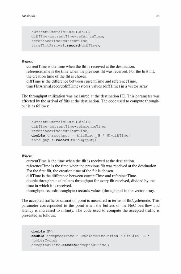
93Analysis
Where:currentTime is the time when the flit is received at the destination.referenceTime is the time when the previous flit was received. For the first flit, the creation time of the flit is chosen.diffTime is the difference between currentTime and referenceTime.timeFlitArrival.record(diffTime) stores values (diffTime) in a vector array.
The throughput utilization was measured at the destination PE. This parameter was affected by the arrival of flits at the destination. The code used to compute through-put is as follows:
currentTime=simTime().dbl();diffTime=currentTime-refernceTime;referenceTime=currentTime;timeFlitArrival.record(diffTime);
currentTime=simTime().dbl();diffTime=currentTime-referenceTime;referenceTime=currentTime;double throughput = (flitSize _ B * 8)/diffTime;throughput.record(throughput);
Where:currentTime is the time when the flit is received at the destination.referenceTime is the time when the previous flit was received at the destination. For the first flit, the creation time of the flit is chosen.diffTime is the difference between currentTime and referenceTime.double throughput calculates throughput for every flit received, divided by the time in which it is received.throughput.record(throughput) records values (throughput) in the vector array.
The accepted traffic or saturation point is measured in terms of flit/cycle/node. This parameter corresponded to the point when the buffers of the NoC overflow and latency is increased to infinity. The code used to compute the accepted traffic is presented as follows:
double BW;double acceptedTraffic = BW/clockTimePeriod * flitSize _ B *numberCyclesacceptedTraffic.record(acceptedTraffic);

94 Bio-Inspired Fault-Tolerant Algorithms for Network-on-Chip
Where:BW is bandwidth in byte per second.acceptedTraffic is measured in flit/cycle/node. It stores values to be saved in the vector array.flitSize_B is the flit size in byte (4 bytes).clockTimePeriod is equal to 0.5 × 10⁹ cycles (1 cycle = 2 ns).numberCycles is the number of clock cycles.acceptedTraffic.record(acceptedTraffic) stores the value (acceptedTraffic) in the vector array.
Another way to compute the saturation point is by using the graphical method by plot-ting the accepted traffic rate vs. latency (cycles), as shown in Figure 5.11. The point on the x-axis where the latency increases to almost infinity is the saturation point.
5.2.1.1 Synaptogenesis Algorithm Using BE per Faulty Router and Interconnect Basis
Initially, the synaptogenesis algorithm was applied on a per-router faulty case. In this case, the complete router was blocked when it became faulty. Due to this, all five ports of the router were blocked, and they were not accessible for traversing the packet to the neighbor routers. Due to this, the number of routing possibilities is also reduced, as all five ports were blocked. This also reduces the performance of the NoC compared to the interconnect faulty case. Therefore, later, all bio-inspired algorithms in the literature were implemented on faulty interconnect basis. In this simulation scenario, the bio-inspired algorithm is only tested for one source and one destination at a time. The faults were introduced on a particular path to test the algorithm.
As can be seen in Figure 5.1, when there were no faulty routers and interconnects, the bandwidth utilization of the interconnect-based algorithm was better compared to the router-based bio-inspired algorithm, as the bandwidth utilization was increased from 1927 MBps to 1989 MBps. The overall bandwidth utilization increase was 5.03% from the router-based to interconnect-based bio-inspired routing algorithms. The reason is that in interconnect-based algorithms, there are more routing paths compared to the faulty router algorithm. Therefore, the bio-inspired algorithm can adapt any alternative path to bypass the fault.
Similarly, the latency of the interconnect-based bio-inspired algorithm was less compared to router-based bio-inspired algorithms. The reason was that as all the ports of the router are blocked and no routing was possible through complete rout-ers, this increases the latency of the flits in the router-based algorithm, as shown in Figure 5.2. The latency of the flits in the interconnect-based algorithm reduced to almost 50 ns from 58 ns when three faults were introduced during the simulation. The overall latency decrease was 10.64% from router-based to interconnect-based bio-inspired routing algorithm.
Similarly, the interflit arrival time was reduced to 7.7 ns from 10 ns when three interconnects and routers became faulty in interconnect-based and router-based bio-inspired algorithms, respectively. The overall interflit arrival time decreased 17.25% from router-based to interconnect-based bio-inspired routing algorithm, as shown in

95Analysis
FIGURE 5.1 Bandwidth vs. number of faults.
FIGURE 5.2 Latency vs. number of faults.
Figure 5.3. This reason was that the interflit arrival time should be more for complete router blockages compared to one interconnect blockage.
The graph in Figure 5.4 shows that the throughput of the improved interconnect-based bio-inspired algorithm also increases 13.75% from the previous router-based algorithm.

96 Bio-Inspired Fault-Tolerant Algorithms for Network-on-Chip
FIGURE 5.3 Interflit arrival time vs. number of faults.
FIGURE 5.4 Throughput vs. number of faults.
To analyze the bio-inspired algorithms, they were thoroughly tested, validated and compared with the algorithms in the literature. For this reason, XY and odd-even routing algorithms were implemented. The results were then compared against the bandwidth, latency, interflit arrival time and throughput parameters. The bio-inspired algorithms have been found to perform better compared to the algorithms in the literature, as described in the following subsections.

97Analysis
5.2.1.2 BandwidthThe BE-based communication services complemented the GT services. At times, GT-based communication channels do not efficiently utilize the bandwidth, and this leads to underutilization of the resources. To efficiently utilize the bandwidth of the NoC, BE communication services were also provided along with the GT service level. The bandwidth, throughput, interflit arrival time and latency of BE and GT architectures depended on the traffic pattern and data flit injection rate. At a higher traffic injection rate, GT connections were preferred, as can be seen in Figure 5.5. At a 100% traffic injection rate, the bandwidth utilization of GT was found to better compared to the overall average TDM (bio-inspired TDM) performance for 10% to 100% injection rates for multiple faults, as there are more delay cycles between packets in the overall average TDM connections. The sprouting BE performed bet-ter compared to TDM-based GT connections. The sprouting BE efficiently utilized the bandwidth by 14.51% compared to 100% injection rate TDM-based connec-tions, while the bandwidth utilization increased to 78.35% when the sprouting BE bandwidth utilization was compared with the bandwidth utilization of the average TDM connections. The sprouting BE performed better compared to TDM connec-tions because of efficient bandwidth utilization compared to time slots allocation in GT-based TDM connections. The time slots divide the available bandwidth among multiple connections in GT algorithms, which at times leads to underutilization.
FIGURE 5.5 Bandwidth vs. number of faults.

98 Bio-Inspired Fault-Tolerant Algorithms for Network-on-Chip
FIGURE 5.6 Latency vs. number of faults.
The sprouting BE also performed better compared to the combined BE-GT algo-rithm by 20.50%, as GT connections at times underutilize the bandwidth. The sprout-ing BE efficiently utilized the bandwidth by 29.86% compared to the synaptogenesis BE. In the BE NoC, the synaptogenesis algorithm took 3 ns to detect the fault, while the sprouting BE quickly detected the fault and sprouts emerged from the neighbor router. The sprouting BE performed better compared to the algorithms in the litera-ture of XY and odd-even by 74.99% and 67.07%, respectively. The fault detection mechanism in the bio-inspired algorithms was more efficient compared to the XY and odd-even algorithm, as bio-inspired algorithms had two-hop neighbor informa-tion. Furthermore, the restriction of turns in XY and odd-even further degraded their performance compared to bio-inspired algorithms. The odd-even routing algorithm performed better compared to XY by 4.75%, as it avoided the circular wait at the NoC due to restrictions in turns.
The overall performance of BE-based algorithms was better compared to overall TDM-based GT connections by 23.44% in terms of bandwidth utilization. Similarly, the combined BE-GT algorithm performed better compared to overall BE- and GT-based algorithms by 6.65% and 15.75%, respectively.
5.2.1.3 LatencyThe sprouting BE had the least end-to-end latency from source PE to destination PE compared to the literature and other bio-inspired algorithms, as shown in Figure 5.6. As the number of faults increased, the latency of the synaptogenesis BE was higher
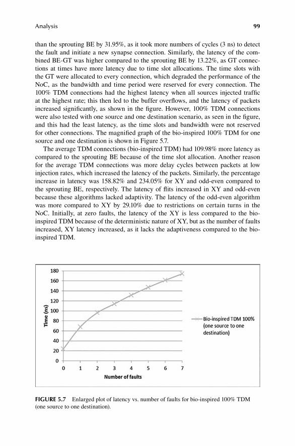
99Analysis
than the sprouting BE by 31.95%, as it took more numbers of cycles (3 ns) to detect the fault and initiate a new synapse connection. Similarly, the latency of the com-bined BE-GT was higher compared to the sprouting BE by 13.22%, as GT connec-tions at times have more latency due to time slot allocations. The time slots with the GT were allocated to every connection, which degraded the performance of the NoC, as the bandwidth and time period were reserved for every connection. The 100% TDM connections had the highest latency when all sources injected traffic at the highest rate; this then led to the buffer overflows, and the latency of packets increased significantly, as shown in the figure. However, 100% TDM connections were also tested with one source and one destination scenario, as seen in the figure, and this had the least latency, as the time slots and bandwidth were not reserved for other connections. The magnified graph of the bio-inspired 100% TDM for one source and one destination is shown in Figure 5.7.
The average TDM connections (bio-inspired TDM) had 109.98% more latency as compared to the sprouting BE because of the time slot allocation. Another reason for the average TDM connections was more delay cycles between packets at low injection rates, which increased the latency of the packets. Similarly, the percentage increase in latency was 158.82% and 234.05% for XY and odd-even compared to the sprouting BE, respectively. The latency of flits increased in XY and odd-even because these algorithms lacked adaptivity. The latency of the odd-even algorithm was more compared to XY by 29.10% due to restrictions on certain turns in the NoC. Initially, at zero faults, the latency of the XY is less compared to the bio-inspired TDM because of the deterministic nature of XY, but as the number of faults increased, XY latency increased, as it lacks the adaptiveness compared to the bio-inspired TDM.
FIGURE 5.7 Enlarged plot of latency vs. number of faults for bio-inspired 100% TDM (one source to one destination).
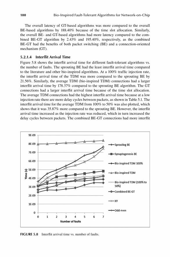
100 Bio-Inspired Fault-Tolerant Algorithms for Network-on-Chip
The overall latency of GT-based algorithms was more compared to the overall BE-based algorithms by 188.40% because of the time slot allocation. Similarly, the overall BE- and GT-based algorithms had more latency compared to the com-bined BE-GT algorithm by 2.43% and 195.40%, respectively, as the combined BE-GT had the benefits of both packet switching (BE) and a connection-oriented mechanism (GT).
5.2.1.4 Interflit Arrival TimeFigure 5.8 shows the interflit arrival time for different fault-tolerant algorithms vs. the number of faults. The sprouting BE had the least interflit arrival time compared to the literature and other bio-inspired algorithms. At a 100% traffic injection rate, the interflit arrival time of the TDM was more compared to the sprouting BE by 21.56%. Similarly, the average TDM (bio-inspired TDM) connections had a larger interflit arrival time by 178.37% compared to the sprouting BE algorithm. The GT connections had a larger interflit arrival time because of the time slot allocation. The average TDM connections had the highest interflit arrival time because at a low injection rate there are more delay cycles between packets, as shown in Table 5.1. The interflit arrival time for the average TDM from 100% to 50% was also plotted, which shows that it was 35.87% more compared to the sprouting BE. However, the interflit arrival time increased as the injection rate was reduced, which in turn increased the delay cycles between packets. The combined BE-GT connections had more interflit
FIGURE 5.8 Interflit arrival time vs. number of faults.

101Analysis
arrival time compared to the sprouting BE by 21.06% because of the time slot alloca-tion. The synaptogenesis BE had a larger interflit arrival time by 43.61% compared to the sprouting BE. The synaptogenesis BE takes 3 ns to detect a fault compared to the sprouting BE. Similarly, the sprouting BE performed better compared to the algorithms in the literature of XY and odd-even by 80.63% and 95.56%, respectively, because of the two-hop neighbor information. The interflit arrival time of Odd-Even algorithm was more compared to XY by 8.27%. The interflit arrival time of XY was less compared to the bio-inspired TDM (100% to 50%) algorithm at zero faults, as it is a deterministic algorithm, which lacks the adaptiveness and follows a fixed path. However, as the number of faults increased, the interflit arrival time of the XY was larger compared to the bio-inspired TDM (100% to 50%) algorithm, as it lacks the efficient fault detection mechanism compared to the bio-inspired algorithm.
The interflit arrival time of the overall GT-based algorithms is larger compared to the overall BE-based algorithms by 64.17% due to the time slot mechanism. Similarly, the overall BE- and GT-based algorithms had a larger interflit arrival time compared to the combined BE-GT algorithm by 0.62% and 65.19%, respectively.
5.2.1.5 ThroughputThe throughput of the sprouting BE was higher compared to the literature and other bio-inspired fault-tolerant algorithms, as shown in Figure 5.9. The sprouting BE throughput was higher compared to the 100% TDM and average TDM connections by 11.71% and 30.36%, respectively, as time slot allocation in the TDM leads to
FIGURE 5.9 Throughput vs. number of faults.
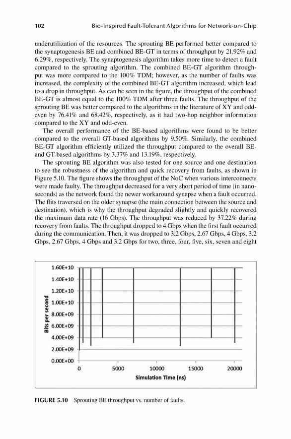
102 Bio-Inspired Fault-Tolerant Algorithms for Network-on-Chip
underutilization of the resources. The sprouting BE performed better compared to the synaptogenesis BE and combined BE-GT in terms of throughput by 21.92% and 6.29%, respectively. The synaptogenesis algorithm takes more time to detect a fault compared to the sprouting algorithm. The combined BE-GT algorithm through-put was more compared to the 100% TDM; however, as the number of faults was increased, the complexity of the combined BE-GT algorithm increased, which lead to a drop in throughput. As can be seen in the figure, the throughput of the combined BE-GT is almost equal to the 100% TDM after three faults. The throughput of the sprouting BE was better compared to the algorithms in the literature of XY and odd-even by 76.41% and 68.42%, respectively, as it had two-hop neighbor information compared to the XY and odd-even.
The overall performance of the BE-based algorithms were found to be better compared to the overall GT-based algorithms by 9.50%. Similarly, the combined BE-GT algorithm efficiently utilized the throughput compared to the overall BE- and GT-based algorithms by 3.37% and 13.19%, respectively.
The sprouting BE algorithm was also tested for one source and one destination to see the robustness of the algorithm and quick recovery from faults, as shown in Figure 5.10. The figure shows the throughput of the NoC when various interconnects were made faulty. The throughput decreased for a very short period of time (in nano-seconds) as the network found the newer workaround synapse when a fault occurred. The flits traversed on the older synapse (the main connection between the source and destination), which is why the throughput degraded slightly and quickly recovered the maximum data rate (16 Gbps). The throughput was reduced by 37.22% during recovery from faults. The throughput dropped to 4 Gbps when the first fault occurred during the communication. Then, it was dropped to 3.2 Gbps, 2.67 Gbps, 4 Gbps, 3.2 Gbps, 2.67 Gbps, 4 Gbps and 3.2 Gbps for two, three, four, five, six, seven and eight
FIGURE 5.10 Sprouting BE throughput vs. number of faults.
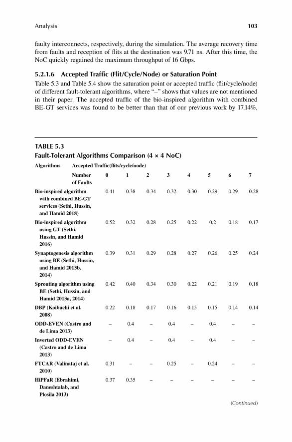
103Analysis
faulty interconnects, respectively, during the simulation. The average recovery time from faults and reception of flits at the destination was 9.71 ns. After this time, the NoC quickly regained the maximum throughput of 16 Gbps.
5.2.1.6 A ccepted Traffic (Flit/Cycle/Node) or Saturation PointTable 5.3 and Table 5.4 show the saturation point or accepted traffic (flit/cycle/node) of different fault-tolerant algorithms, where “–” shows that values are not mentioned in their paper. The accepted traffic of the bio-inspired algorithm with combined BE-GT services was found to be better than that of our previous work by 17.14%,
TABLE 5.3Fault-Tolerant Algorithms Comparison (4 × 4 NoC)Algorithms Accepted Traffic(flits/cycle/node)
Number 0 1 2 3 4 5 6 7of Faults
Bio‑inspired algorithm 0.41 0.38 0.34 0.32 0.30 0.29 0.29 0.28with combined BE‑GT services (Sethi, Hussin, and Hamid 2018)
Bio‑inspired algorithm 0.52 0.32 0.28 0.25 0.22 0.2 0.18 0.17using GT (Sethi, Hussin, and Hamid 2016)
Synaptogenesis algorithm 0.39 0.31 0.29 0.28 0.27 0.26 0.25 0.24using BE (Sethi, Hussin, and Hamid 2013b, 2014)
Sprouting algorithm using 0.42 0.40 0.34 0.30 0.22 0.21 0.19 0.18BE (Sethi, Hussin, and Hamid 2013a, 2014)
DBP (Koibuchi et al. 0.22 0.18 0.17 0.16 0.15 0.15 0.14 0.142008)
ODD‑EVEN (Castro and – 0.4 – 0.4 – 0.4 – –de Lima 2013)
Inverted ODD‑EVEN – 0.4 – 0.4 – 0.4 – –(Castro and de Lima 2013)
FTCAR (Valinataj et al. 0.31 – – 0.25 – 0.24 – –2010)
HiPFaR (Ebrahimi, 0.37 0.35 – – – – – –Daneshtalab, and Plosila 2013)
(Continued)
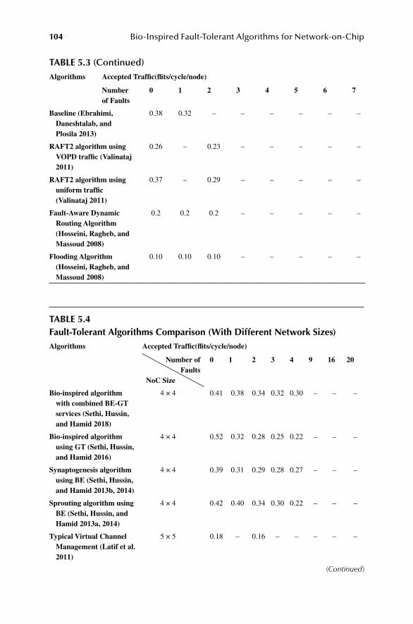
104 Bio-Inspired Fault-Tolerant Algorithms for Network-on-Chip
Algorithms Accepted Traffic(flits/cycle/node)
Number 0 1 2 3 4 5 6 7of Faults
Baseline (Ebrahimi, 0.38 0.32 – – – – – –Daneshtalab, and Plosila 2013)
RAFT2 algorithm using 0.26 – 0.23 – – – – –VOPD traffic (Valinataj 2011)
RAFT2 algorithm using 0.37 – 0.29 – – – – –uniform traffic (Valinataj 2011)
Fault‑Aware Dynamic 0.2 0.2 0.2 – – – – –Routing Algorithm (Hosseini, Ragheb, and Massoud 2008)
Flooding Algorithm 0.10 0.10 0.10 – – – – –(Hosseini, Ragheb, and Massoud 2008)
TABLE 5.4Fault-Tolerant Algorithms Comparison (With Different Network Sizes)Algorithms Accepted Traffic(flits/cycle/node)
Number of 0 1 2 3 4 9 16 20Faults
NoC Size
Bio‑inspired algorithm 4 × 4 0.41 0.38 0.34 0.32 0.30 – – –with combined BE‑GT services (Sethi, Hussin, and Hamid 2018)
Bio‑inspired algorithm 4 × 4 0.52 0.32 0.28 0.25 0.22 – – –using GT (Sethi, Hussin, and Hamid 2016)
Synaptogenesis algorithm 4 × 4 0.39 0.31 0.29 0.28 0.27 – – –using BE (Sethi, Hussin, and Hamid 2013b, 2014)
Sprouting algorithm using 4 × 4 0.42 0.40 0.34 0.30 0.22 – – –BE (Sethi, Hussin, and Hamid 2013a, 2014)
Typical Virtual Channel 5 × 5 0.18 – 0.16 – – – – –Management (Latif et al. 2011)
(Continued)
TABLE 5.3 (Continued)

105Analysis
Algorithms Accepted Traffic(flits/cycle/node)
Number of 0 1 2 3 4 9 16 20Faults
NoC Size
PVS (Latif et al. 2011) 5 × 5 0.22 – 0.20 – – – – –
FVS (Latif et al. 2011) 5 × 5 0.23 – – – – – – –
A Reconfigurable Routing 5 × 5 0.28 0.27 0.22 0.16 0.15 – – –Algorithm (Zhang, Greiner, and Taktak 2008)
RAFT (Valinataj, 5 × 5 – – – – – 0.28 – –Liljeberg, and Plosila 2013)
Agent‑based routing 5 × 5 – – – – – 0.3 – –(Valinataj, Liljeberg, and Plosila 2013)
XY (Zhang, Han, and 8 × 8 0.36 – – – – – 0.25 –Zhang 2013)
FFAR (Zhang, Han, and 8 × 8 0.35 – – – – – 0.28 –Zhang 2013)
OE (Pasricha et al. 2010) 9 × 9 – 0.04 – – – – – 0.036
IOE (Pasricha et al. 2010) 9 × 9 – 0.035 – – – – – 0.03
OE+IOE (Pasricha et al. 9 × 9 – 0.06 – – – – – 0.0652010)
TABLE 5.4 (Continued)
while compared to the algorithms in the literature, it was better by 38.99%. The bio-inspired algorithm using GT had the best saturation point of 0.52 at zero faults com-pared to the fault-tolerant algorithms in the literature that show the efficiency and simplicity of the algorithm. Figure 5.11 shows the saturation point of the GT-based NoC as the number of faults is increased. This also demonstrates that the bio-inspired algorithm quickly found the path from the source PE to destination PE when there was no fault (1 cycle = 2 ns).
Most of the fault-tolerant algorithms have been found to be not thoroughly tested using different numbers of faults compared to the bio-inspired algorithm. The bio-inspired algorithms were also compared with the DBP (Koibuchi et al. 2008) fault-tolerant algorithm that is a thoroughly analyzed, tested and presented algorithm in the literature. The bio-inspired algorithm with combined BE-GT performed better compared to the DBP fault-tolerant algorithm by 99.24%. Similarly, the bio-inspired algorithm using GT and the bio-inspired algorithm using BE (synaptogenesis and sprouting) performed better by 63.36% and 72.12%, respectively, compared to the DBP fault-tolerant algorithm.
The accepted traffic rate of the bio-inspired NoC using GT was less compared to the BE-based bio-inspired algorithms. This was expected, as these algorithms

106 Bio-Inspired Fault-Tolerant Algorithms for Network-on-Chip
are based on the BE scenario. In BE, the bandwidth and throughput utilization were found to be better compared to GT-based algorithms. The efficient utilization of the TDM-based GT connections depended on the burst of traffic from the source or from neighbor routers. Usually, TDM-based virtual circuits are allocated to those PEs that need guaranteed and faster services, while BE algorithms are packet-switching techniques that utilize all the available bandwidth without any reservation. The satu-ration point of the algorithms mentioned in (Castro and de Lima 2013) was slightly higher in three faulty cases (one, three and five). The saturation point of 0.4 for three different faulty cases was not a common behavior in the literature. Usually, the satu-ration point decreases as the number of faults is increased. The network saturates early, as the network has fewer paths for packets to traverse through and these paths are occupied by all the PEs available on the NoC. For this reason, the NoC satu-rates early, and it leads to overflow of buffers and queues. Moreover, the algorithms (Castro and de Lima 2013; Ebrahimi, Daneshtalab, and Plosila 2013; Valinataj 2011) (Hosseini, Ragheb, and Massoud 2008; Latif et al. 2011; Zhang, Greiner, and Taktak 2008; Valinataj, Liljeberg, and Plosila 2013; Zhang, Han, and Zhang 2013; Pasricha et al. 2010) were only tested with a traffic injection rate from 10% to 50%, while the bio-inspired algorithms were tested with a 10% to 100% injection rate. The bio-inspired NoC-accepted traffic is better than the fault-tolerant algorithms (Valinataj et al. 2010) for different faulty cases.
SUMMARY
The bio-inspired algorithms with BE, GT and combined BE-GT services per-formed better compared to the algorithms in the literature and had better through-put and bandwidth utilization. The overall BE-based algorithms efficiently utilized
FIGURE 5.11 Accepted traffic for various numbers of faults.

107Analysis
the bandwidth and maximized the throughput compared to GT-based algorithms. Similarly, the interflit arrival time and latency of the overall BE-based algorithms were less compared to the GT-based algorithms. The results showed that the bio-inspired NoC algorithm using combined BE-GT communication services performed better compared to fault-tolerant algorithms in the literature.
REFERENCES
Ben-Itzhak, Yaniv, Eitan Zahavi, Israel Cidon, and Avinoam Kolodny. 2012. “HNOCS: Modular open-source simulator for heterogeneous NoCs.” 2012 International Conference on Embedded Computer Systems (SAMOS).
Bolotin, Evgeny, Israel Cidon, Ran Ginosar, and Avinoam Kolodny. 2004. “Cost consider-ations in network on chip.” INTEGRATION, the VLSI Journal 38 (1):19–42.
Byrne, Michael D. 2013. “How many times should a stochastic model be run? An approach based on confidence intervals.” Proceedings of the 12th International Conference on Cognitive Modeling, Ottawa.
Castro, Helano S, and Otavio Alcantara de Lima. 2013. “A fault tolerant NoC architecture based upon external router backup paths.” 2013 IEEE 11th International New Circuits and Systems Conference (NEWCAS).
Ebrahimi, Masoumeh, Masoud Daneshtalab, and Juha Plosila. 2013. “High performance fault-tolerant routing algorithm for NoC-based many-core systems.” 2013 21st EUROMICRO International Conference on Parallel, Distributed, and Network-Based Processing.
Hosseini, Amir, Tamer Ragheb, and Yehia Massoud. 2008. “A fault-aware dynamic routing algorithm for on-chip networks.” 2008 IEEE International Symposium on Circuits and Systems.
Koibuchi, Michihiro, Hiroki Matsutani, Hideharu Amano, and Timothy Mark Pinkston. 2008. “A lightweight fault-tolerant mechanism for network-on-chip.” Proceedings of the Second ACM/IEEE International Symposium on Networks-on-Chip.
Latif, Khalid, Amir-Mohammad Rahmani, Kameswar Rao Vaddina, Tiberiu Seceleanu, Pasi Liljeberg, and Hannu Tenhunen. 2011. “Enhancing performance sustainability of fault tolerant routing algorithms in NoC-based architectures.” 2011 14th EUROMICRO Conference on Digital System Design.
Pasricha, Sudeep, Yong Zou, Dan Connors, and Howard Jay Siegel. 2010. “OE+ IOE: A novel turn model based fault tolerant routing scheme for networks-on-chip.” 2010 IEEE/ACM/IFIP International Conference on Hardware/Software Codesign and System Synthesis (CODES+ ISSS).
Patooghy, Ahmad, Seyed Ghassem Miremadi, and Mahdi Fazeli. 2010. “A low-overhead and reliable switch architecture for Network-on-Chips.” Integration 43 (3):268–278.
Sethi, Muhammad Athar Javed, Fawnizu Azmadi Hussin, and Nor Hisham Hamid. 2013a. “Implementation of biological sprouting algorithm for NoC fault tolerance.” 2013 IEEE International Conference on Circuits and Systems (ICCAS).
Sethi, Muhammad Athar Javed, Fawnizu Azmadi Hussin, and Nor Hisham Hamid. 2013b. “Synaptogenesis based bio-inspired NoC fault tolerant interconnects.” 2013 IEEE International Conference on Control System, Computing and Engineering.
Sethi, Muhammad Athar Javed, Fawnizu Azmadi Hussin, and Nor Hisham Hamid. 2014. “Bio-inspired NoC fault tolerant techniques.” 2014 5th International Conference on Intelligent and Advanced Systems (ICIAS).
Sethi, Muhammad Athar Javed, Fawnizu Azmadi Hussin, and Nor Hisham Hamid. 2016. “Biologically inspired network on chip fault tolerant algorithm using time division multi-plexing.” 2016 6th International Conference on Intelligent and Advanced Systems (ICIAS).

108 Bio-Inspired Fault-Tolerant Algorithms for Network-on-Chip
Sethi, Muhammad Athar Javed, Fawnizu Azmadi Hussin, and Nor Hisham Hamid. 2018. “Bio-inspired network on chip having both guaranteed throughput and best effort ser-vices using fault-tolerant algorithm.” IEEJ Transactions on Electrical and Electronic Engineering 13 (8):1153–1162.
Team, R Core. 2013. “R: A language and environment for statistical computing.”Tedesco, Leonel, Aline Mello, Diego Garibotti, Ney Calazans, and Fernando Moraes. 2005.
“Traffic generation and performance evaluation for mesh-based NoCs.” Proceedings of the 18th Annual Symposium on Integrated Circuits and System Design.
Valinataj, Mojtaba. 2011. “Evaluation of fault-tolerant routing methods for NoC architec-tures.” 2011 14th EUROMICRO Conference on Digital System Design.
Valinataj, Mojtaba, Pasi Liljeberg, and Juha Plosila. 2013. “Enhanced fault-tolerant Network-on-Chip architecture using hierarchical agents.” 2013 IEEE 16th International Symposium on Design and Diagnostics of Electronic Circuits & Systems (DDECS).
Valinataj, Mojtaba, Siamak Mohammadi, Juha Plosila, and Pasi Liljeberg. 2010. “A fault-tolerant and congestion-aware routing algorithm for networks-on-chip.” 13th IEEE Symposium on Design and Diagnostics of Electronic Circuits and Systems.
Zhang, Shijian, Guodong Han, and Fan Zhang. 2013. “Very fine-grained fault-tolerant routing algorithm of NoC based on buffer reuse.” 2013 IEEE 4th International Conference on Software Engineering and Service Science.
Zhang, Zhen, Alain Greiner, and Sami Taktak. 2008. “A reconfigurable routing algorithm for a fault-tolerant 2D-mesh network-on-chip.” 2008 45th ACM/IEEE Design Automation Conference.

109
6 Conclusion and Future Work
Network on Chip (NoC) refers to a communication standard for on-chip networks. NoC has replaced the traditional bus and crossbar interconnection of System on Chip (SoC) components. Multiprocessor SoC (MPSoC) is also unable to cope with the globally asynchronous locally synchronous (GALS) communication. Therefore, this leads to the concept of an NoC that can provide the modularity, scalability and efficient reuse of the resources with high bandwidth.
The excessive and parallel communication requirements of heterogeneous pro-cessing elements (PEs) in the NoC have made the communication structure very complicated. The size of the devices is scaled down to support the complexity, which has contributed to the faults. Fault tolerance is becoming a very important concept as more devices are favoring NoC. Fault tolerance separates the data communications from the on-chip communication mechanism. Fault tolerance is the way to cope with both permanent and temporary faults. Permanent faults are due to the physical damage to resources on the NoC, such as electromigration, die-electric breakdown, manufacturing defects or any physical damage. They can be addressed with the help of redundant routers, interconnects or resources (PEs). Temporary faults are due to changes in voltage, temperature, congestion in routers or faults. These faults can be addressed with fault-tolerant routing algorithms.
Different fault-tolerant algorithms have been proposed. Deterministic, stochastic, fully adaptive and partial adaptive routing algorithms are four broad categories of fault-tolerant algorithms. However, all of these algorithms do not entirely address the drawbacks. Traditional fault-tolerant algorithms also suffer from adaptivity and robustness limitations. Biological brain-inspired fault-tolerant algorithms have been proposed, making the NoC more fault-tolerant and robust. Synaptogenesis and sprouting are two of these biological brain-inspired algorithms. The bio-inspired algorithm “synaptogenesis” solves the problem of dynamic interconnections between various PEs by adapting the mechanism of the growth cone present at the top of the axon terminal and the dendrites. The “sprouting” algorithm helps to recover from faults by generating a sprout from the neighbor router. The bio-inspired algorithm improves the overall performance of the NoC by rerouting the packets to the newly established synapse to bypass the faulty interconnects.
In the bio-inspired algorithm, the “synap” packet is generated by source PE to have a connection with the destination PE. Upon reception of the “synap” packet at the router, the router sends information set (IS) packets to neighbor routers so they have two-hop information. The neighbor routers reply with IS response pack-ets. After receiving IS response packets and based on the destination PE, the router prioritizes the path toward the destination. After traversing the routers, the “synap”

110 Bio-Inspired Fault-Tolerant Algorithms for Network-on-Chip
signal is reached at the destination. The destination PE sends a route reply signal to the source PE. Data flits traverse over this connection until there are no faults. When interconnects become faulty during the communication, the neighbor router detects the fault and initiates the synapse connection (sprout) between the current router to the older synapse or to the destination router. If there is no older synapse to connect with, the sprout is directly connected with the destination PE. The connection with the older synapse avoids the traversal of unnecessary routers—this makes the algo-rithm robust and fault-tolerant.
The bio-inspired algorithm was implemented via three communication setups; those are guaranteed throughput (GT), best effort (BE) and combined BE-GT using three different NoC architectures. There are basically two broad categories of qual-ity of services parameters in NoC, namely GT service and BE service. In GT, the resources on the network are reserved for a particular time period between source and destination PEs. The circuit-switching or connection-oriented mechanism of packet switching is mainly used to allocate resources and guarantee throughput. GT connections are usually allocated to real-time traffic because of high traffic and less latency requirements. GT connections address the worst-case scenario because the resources can be silent for a particular time, which makes the bandwidth utilization low at times. BE services complement the GT connections because of their underuti-lization of the channel bandwidth. BE is the packet-switching concept that utilizes the unallocated bandwidth to sources and other routers. BE traffic does not allocate any resources on the NoC. The BE service represents the average-case scenario. The channel is always utilized when the source and destination need it. Video processing and multimedia applications are examples of GT critical traffic, while cache updates are examples of BE noncritical traffic.
BE services were provided using packet-switching techniques that have credit-based flow control. In credit-based flow control, there was a credit counter at the router, which controls the flow of flits between routers. If the credit counter is zero, then this port is busy and not allowed to send more flits until the neighbor router replies with the credit increment packet after receiving the flit. The GT service was provided using time division multiplexing (TDM). In TDM, the output link band-width was divided using time period slots and allocated to multiple virtual channels. To avoid the head of line (HOL) blocking, multiple buffers were allocated at the input port. The HOL problem occurred due to the blockage of header flits. The multiple buffers at the input port were allocated to each virtual channel. In the GT service, no flow control technique was required, as the resources were reserved for a particular time period. The results showed that the bio-inspired NoC algorithm using BE, GT and combined BE-GT communication services performed better compared to the fault-tolerant algorithms found in the literature.
6.1 FUTURE WORK
The future work should include the implementation of a complete bio-inspired NoC in a field programmable gate array (FPGA) and further optimize the algorithm and delay the saturation point. Another possible future project would be to update the

111Conclusion and Future Work
routing algorithm so that it can avoid more faulty and congested paths in the NoC by processing the information received from neighbor routers, where the information is received in the form of ISW, ISE, ISS and ISN packets. Moreover, future work should also include further testing of the bio-inspired algorithm on different NoC sizes and topologies.

113
Appendix A

Surv
ey o
f No
C A
rch
itec
ture
s: S
tud
y 1
wer
gy
oP D
issi
pati
on/
Ene
rC
onsu
mpt
ion
– – – –
—R
oute
r ar
ea is
2 e λ60
00X
5000
impl
emen
tatio
n v
of s
witc
h ha
0.59
mm
2
eaA
r
– —A
SIC
50,0
00
tran
sist
ors
–
NoC
Siz
eor
exp
erim
ents
)(f —
256
term
inal
s—
10X
10 p
artia
l cr
ossb
ar
3X3
4X4
Mes
h
– –
Impl
emen
tati
on
Sim
ulat
ion
& ,
aral
lel
Synt
hesi
s(C
ycle
Acc
urat
e Sy
stem
Si
mul
ator
CA
SS)
—Si
mul
atio
n(N
SIM
PIn
terc
onne
ct
and
Sim
pleS
cala
r)
&—
Synt
hesi
s (A
ltera
Q
uart
us)
– Sim
ulat
or
ypes
Con
nect
ion
T
1–1,
bro
adca
st
1–1
(Poi
nt-t
o-po
int
com
mun
icat
ion)
– –
Ope
n ceSo
ur
– – – –
opol
ogy
ree
at T
Mes
h
us-b
ased
)
T Supp
orte
d (2
D)
F Fold
ed to
rus
Cus
tom
(b
NoC
Clo
ckin
g M
echa
nism
Sync
hron
ous
Sync
hron
ous
Sync
hron
ous
–
alua
tion
ar
amet
ers
—M
essa
ge
y ork
late
nc
thro
ughp
ut—
Net
w
—N
umbe
r of
y
wer
ime
cycl
es v
s.
num
ber
of
Ev
P —A
rea
core
s
Lin
k —
T—
utili
zatio
n—
Use
d lin
k—
Are
a—
Freq
uenc
—A
rea
—Po
–
echn
ique
s
switc
hing
mec
hani
sm
Swit
chin
g
orm
hole
usin
g cr
edit
T Wor
mho
le
switc
hing
&
head
er
W Hea
der
–
et et
QoS ac
k
ack
BE
GS
P P
e an
d ut
ed
aram
eter
s
Rou
ting v
dist
rib
Ada
pti
Stat
ic
Det
erm
inis
tic
–
Com
pari
son
P
Lin
k Sh
arin
g
et
ack sw
itchi
ngP (r
ound
-rob
in
arbi
trat
ion)
et
ack sw
itchi
ng
(TD
M)
switc
hing
switc
hing
P Cir
cuit et
ack (T
DM
reso
urce
ar
bitr
atio
n sc
hem
e)
P Usi
ng
Gue
rrie
r an
d
) )
)
chit
ectu
res
Gre
iner
200
8
Prog
ram
mab
le
amin
atha
n,
2000
2001 )
Inte
rcon
nect
Dal
ly
ork)
Lia
ng,
essi
er
e Sy
stem
on
wle
s
ork
Chi
p)
SPIN
(
(
Ar
(Sca
labl
e o ard
2001
Net
w v
aSO
C (
Sw and
T(A
dapt
i
Dal
ly e
t al.
(an
d T
Mic
roN
etw
ing
W
S. N
o.
1 2 3 4

)deu
cons
umes
20
955m
W ninto
Switc
h C(
– –
1400
00 n
umbe
r of
tr
ansi
stor
s ar
e re
quir
ed f
or
VC
=4
tran
sist
ors
115,
000
–
o lin
ks f
or
com
mun
icat
ion
er a
nd
er
x switc
h
us
ard
and
x
erse
w forw v
re
—M
ultip
lede
mul
tiple
topo
logy
—In
itiat
or a
nd
get
switc
h
8 no
de ar
—T T
—C
omm
and
—R
espo
nse
with
sta
r or
bto
polo
gy
Hav
ing
ring
alo
ng
Sim
ulat
or
Smar
t car
d ch
ip
(ASI
C)
Sim
ulat
ion
&
Synt
hesi
s(V
HD
L)
1–1
1–1,
mul
ticas
t
–
– – –
Oct
agon
nyA H
iera
rchi
cal
Nod
es in
rin
g of
gr
ee 3
de
Asy
nchr
onou
s
Glo
bally
A
sync
hron
ous
Loc
ally
Sy
nchr
onou
s (G
AL
S) o
r A
sync
hron
ous
y vs
. ut
iliza
tion
et lo
ss
gres
s
—L
aten
c
ack
prob
abili
ty
vs. e
queu
e si
ze—
Nod
es v
s.
links
vs.
ho
psN
umbe
r of
link
s vs
. num
ber
of n
odes y
—P
—A
rea
—T
hrou
ghpu
t—
Lat
enc
–
orm
hole
sw
itchi
ng
Hea
der
with
se
para
te
cont
rol l
ines
(E
OP)
W Hea
der
et et
ack
ack
GS
P P
Det
erm
inis
tic
rout
ing e
Sour
ce
Ada
ptiv
et &
ci
rcui
t sw
itchi
ng
et
et
ack
ack sw
itchi
ng
ack sw
itchi
ng
P P P
Kar
im, y
orto
sa )
GO
N (
AN
guye
n, a
nd D
e
Bai
nbri
dge
TE
O
2002
)
O Sigu
enza
-T
OC
T
CH
AIN
(an
d Fu
rber
200
2
PR( an
d N
urm
i 200
2
5 7 6

wer
gy
oP D
issi
pati
on/
Ene
rC
onsu
mpt
ion
– 25W
– – –
2
ea tran
sist
ors
Ar
– 122
mill
ion
Are
a of
the
rout
er
is 0
.26m
m
– –
NoC
Siz
eor
exp
erim
ents
)(f 5X
5 M
esh
1024
tile
s
– 6X6
Mes
h
8X8
Mes
h
Impl
emen
tati
on
Sim
ulat
ion
IBM
SA
-27E
(A
SIC
)
(NS-
2)
Sim
ulat
or
Synt
hesi
s
Sim
ulat
ion
&
ASI
C(C
ycle
acc
urat
e)
ypes
Con
nect
ion
T
Mul
tipat
h
– – 1–1,
mul
ticas
t
1–1
Ope
n ceSo
ur
– – – No
–
opol
ogy
T Supp
orte
d (2
D)
Mes
h
Mes
h
Mes
h
Mes
h
Mes
h
NoC
Clo
ckin
g M
echa
nism
Glo
bally
A
sync
hron
ous
Loc
ally
Sy
nchr
onou
s (G
AL
S)
Glo
bally
Sy
nchr
onou
s w
ith
mes
ochr
onou
s or
as
ynch
rono
us
links
– – Mes
ochr
onou
s
alua
tion
E
v aram
eter
s y
ork
P —Pe
rfor
man
ce—
Util
izat
ion y
—C
apac
ityir
eabi
lity
—W
—D
elay
—B
andw
idth
—Po
sitio
n of
pa
ds &
re
peat
ers
– – —A
rea
y—
Lat
enc
—T
hrou
ghpu
t—
Freq
uenc
—Sw
itch
size
—Se
rvic
e C
lass
—Pr
ogra
mm
ing
y
mod
el
—L
aten
c—
Net
wus
age
—Fr
eque
nc
Swit
chin
g ec
hniq
ues
orm
hole
sw
itchi
ng
orm
hole
sw
itchi
ng
ard
forw
switc
hing
T W W Stor
e &
Wor
mho
le
none
uted
et et
QoS ac
k
ack ro
utin
g w
ith B
E)
P P – GS,
BE
(Dis
trib
GS,
BE
aram
eter
s
Rou
ting
Det
erm
inis
tic
Dim
ensi
on
Det
erm
inis
tic
Sour
ce a
long
w
ith
cont
entio
n
uted
orde
r
free
Dis
trib
Com
pari
son
P
Lin
k Sh
arin
g
et
et
switc
hing
et
ack sw
itchi
ng
ack sw
itchi
ng
et
ack sw
itchi
ng
usin
g T
DM
for
BE
&
no
ack ar
bitr
atio
n fo
r G
T)
switc
hing
P P P P (rou
nd-r
obin
Cir
cuit
aylo
r et
al.
ema
)
es umar
)
Com
mun
icat
ion
Het
erog
eneo
us
) iklu
nd
K el
grat
ion
of
Rijp
k
et a
l. 20
02 W
v orse
ll F
chit
ectu
r
Ele
men
ts)
T )20
02
)20
02
et a
l. 20
03
Ar
CL
ICH
É (
(Chi
p L
e
Ecl
ipse
(
Æth
erea
l (
US
(
Inte
W (
RA
SoC
B and
Liu
200
3
S. N
o.
8 9 10 11 12

)d: :
e po
wer
co
nsum
ptio
n
ame
pow
er
euni
0.95
mW
(5
MH
z)
(50
MH
z)3.
20 m
W nto
C
ad fr co
nsum
ptio
n
– Cor
3.55
mW
(5
MH
z)29
.85
mW
(5
0 M
Hz)
(
– P
Map
ping
:—
631
LU
Ts,
-31
6
ASI
C M
appi
ng:
tran
sist
ors ates
AN
D
2
x II
Slic
es
—2.
930
—40
,000
—10
,000
g
2-in
put N
gate
sSi
ngle
Cha
nnel
:
hann
els:
erte c
V 4000
4 vi
rtua
l
1200
0
Switc
h ar
ea is
0.
5 m
m
5X5
&2X
2M
esh
4X4
Cro
ssba
r
3X3
Cro
ssba
r
IIx
actu
red
Sim
ulat
ion, irte
FPG
A V
Sim
ulat
ion
(VH
DL
)
man
uf(H
P165
00 lo
gic
anal
ysis
)
Chi
p
ving
at t
he
1-1,
One
por
tse
ndin
g an
dre
cei
sam
e tim
e
1–1,
mul
ticas
t
1–1
(Poi
nt-t
o-po
int)
– – –
at
Mes
h
But
terfl
y f
tree
Mes
h
Sync
hron
ous
Asy
nchr
onou
s
Sync
hron
ous
fer
size
vs
. num
ber
of lo
ok u
p ta
bles
(L
UT
)fe
r si
ze v
s.
num
ber
of
y—
Thr
ough
put
—N
umbe
r of
yc
les
requ
ired
to
er
ets
ates v
g cloc
k c
deli
pack
—T
hrou
ghpu
t vs
. num
ber
of v
irtu
al
chan
nels
—B
uf
Buf
—L
aten
c
—A
rea
—Si
licon
are
a co
nsum
ed b
y th
e sw
itche
s
Func
tiona
lity
orm
hole
sw
itchi
ng
(Hea
der
cont
rol b
its)
Wor
mho
le
switc
hing
W Hea
der
et et
ack
ack
BE
P P
XY
Sour
ce
Stat
ic
et
switc
hing
et
ack
ack sw
itchi
ng s
usin
g V
C’
switc
hing
P Cir
cuit
(rou
nd-r
obin
ar
bitr
atio
n)
P
Mor
aes
) ande
HE
RM
ES
(et
al.
2004
) Pet
al.
2003 el
v
mul
tile
inte
rcon
nect
)
OC
N (
Hen
riks
son,
W
iklu
nd, a
nd L
iu
BID
I-M
IN (
(Bid
irec
tiona
l
2003
) (V
LSI
Im
plem
enta
tion
of a
Sw
itch
for
On-
chip
or
k)N
etw
13 14 15

wer
o
Dis
sipa
tion
/gy
P Ene
rC
onsu
mpt
ion
– 264m
W
–
—Sm
alle
r co
re
confi
gura
tion
requ
ire
420
logi
c
ger
core
co
nfigu
ratio
n re
quir
e 17
54
logi
c ce
lls
2
—A
sw
itch
with
on
ly B
E s
ervi
ces
uses
136
95
ates
.A
ND
gith
VC
ea cells
capa
bilit
y th
e g 13
896
Ar
—L
ar
64.8
mm
N ate
coun
t
—W in
crea
ses
to
NoC
Siz
e
expe
rim
ents
)
2X2
Cro
ssba
r16
Mas
ter
& 1
6 esv
Sla
or
(f – 4X4
Mes
h
Impl
emen
tati
on
Synt
hesi
ze(A
ltera
Qua
rtus
II)
– Sim
ulat
ion
&Sy
nthe
sis
Con
nect
ion
ypes
T – – 1–1,
mul
ticas
t
Ope
n ceSo
ur s
– – Ye
(on
requ
est)
opol
ogy
T Supp
orte
d
orus
(2D
)
Mes
h, T
Star
—M
esh
NoC
Clo
ckin
g M
echa
nism
Asy
nchr
onou
s
Ples
ichr
onou
s
Sync
hron
ous
efor
ms
of
alua
tion
ar
amet
ers
—A
rea
vs. F
IFO
its
)de
pth
(fl—
Are
a vs
. Dat
a w
idth
(bi
ts)
are
el
ork
vera
ge
late
ncy
vera
ge
op le
v vaw on
-chi
p ne
tw
band
wid
th—
The
oret
ical
H
ardw
stud
y
Ev
P T —A
—A
Swit
chin
g ec
hniq
ues
switc
hing
Wor
mho
le
switc
hing
T (hea
der)
Fast
cut
-thr
ough
Hea
ders
et
defle
ctio
n ro
utin
g, it
QoS ac
k addr
ess
the
cong
estio
n co
ntro
l)
P – GS,
BE
(u
sing
Rou
ting
Det
erm
inis
tic &
so
urce
bas
ed
aram
eter
s e
(XY
)
Defl
ectiv
–
Com
pari
son
P
Lin
k Sh
arin
g
et
et
(VC
’
ack sw
itchi
ng
ack sw
itchi
ng
(TD
M u
sing
lo
op
cont
aine
r s)
)
P – P
;
chit
ectu
res
Zef
erin
o an
d Su
sin
Star
Con
nect
ed
Lee
)
Peno
lazz
i and
g et
al.
2003
)
et a
l. 20
03
Nos
trum
( Ja
ntsc
h 20
06M
illbe
r20
04)
Ar
SoC
IN (
OC
N (
S. N
o.
16 17 18

)deuni
oC
ower
(M
W)
P
elat
ed N
oC
93.
66
for
the
MP
EG
4 nt(
r confi
gura
tion
:
– — Mes
h:11
4.36
Cus
tom
1:
110.
66C
usto
m 2
:
–
—C
lock
dom
ain
2
2
—C
ross
bar
area
is
2
—Pi
pelin
e re
peat
er
2
erte
rs a
rea
v
or
otal
are
a is
4.
15 m
m
1.75
mm
con
is 0
.2 m
m
Ar
—T is
0.0
25m
m )fea
(m
m2
the
MP
EG
4 el
ated
NoC
r co
nfigu
rati
on:
— Mes
h:1.
31C
usto
m 1
:0.
86C
usto
m 2
:0.
71
–
Cro
ssba
r
4X4
Cro
ssba
r
3 R
ings
with
36
reso
urce
s
16X
16
abri
cate
&
—A
SIC
—F C
hara
cter
ized
Sim
ulat
or &
Sy
nthe
sis
(Sys
tem
C &
X
pipe
sCom
pile
r)
Sim
ulat
ion
(Sys
tem
C)
1–1,
bro
adca
st
1–1
(Poi
nt-t
o-po
int)
1–1
– – –
gula
r
Stru
ctur
e
Cro
ssba
r
Irre
Rin
g
Glo
bally
A
sync
hron
ous
Loc
ally
Sy
nchr
onou
s (G
AL
S)
Sync
hron
ous
Asy
nchr
onou
s
—Fr
eque
ncy
et y
vs.
wer
erag
e v pack
late
ncba
ndw
idth
utio
n
gy—
Lat
ency
olta
ge fic
dist
rib
—A
rea
—A
rea
raf
stre
ss
—E
ner
—V
—Po
—A
—T m
easu
rem
ent
orm
hole
sw
itchi
ng
Cro
ssba
r
(Go-
back
-N)
ard
forw
W Stor
e an
d
et et
ack
ack
GS
P P
Det
erm
inis
tic
Sour
ce-b
ased
de
term
inis
tic
(Str
eet s
ign
uted
and
rout
ing)
cong
estio
n D
istr
ib
free
switc
hing
Cir
cuit et
switc
hing
s)
(VC
’
et
ack
ack sw
itchi
ng
P P
Lin
es
Ber
tozz
i an
d B
enin
i
Sam
uels
son
umar
)20
04
NoC
Roa
d N
oC
Xpi
pes
(
2004
) ) (R
ing
xus
(
( and
K20
04
Arc
hite
ctur
e)
Ne 2
R
19 20 21

wer
gy
oP D
issi
pati
on/
Ene
rC
onsu
mpt
ion
– – –
2 λ
: 293
at
ion
: 354
no.
ile s
ize
rang
es
to 3
0000
X
2 λ : 380
no.
no. o
f sl
ices
hann
el
obin
from
10
000X
1000
0
3000
0
No
arbi
tr
ixed
cpr
iori
tyof
slic
es
prio
rity
of s
lices
Rou
nd-r
14 m
m2
eaA
r
T F
or e
xper
imen
ts)
9, 1
6, 2
5, 3
6, 4
9
aces
(cor
es)
NoC
Siz
e
core
s
inte
rf
(f – 64
Impl
emen
tati
on
—Si
mul
ator
(tim
ing
accu
rate
)
desc
ript
ion
—FP
GA el)
FPG
A(X
ilink
XC
V40
0E)
est c
hip
usin
g H
DL
gist
er tr
ansf
er
vle
T (re
Con
nect
ion
ypes
T 1–1,
mul
ticas
t
– –
Ope
n ceSo
ur
– – –
Topo
logy
Su
ppor
ted
xibl
e
(2D
)
Mes
h
Fle
Fat t
ree
NoC
Clo
ckin
g M
echa
nism
Glo
bally
A
sync
hron
ous
Loc
ally
Sy
nchr
onou
s (G
AL
S)
Asy
nchr
onou
s
Sync
hron
ous
—A
SoC
vs.
hi
erar
chic
al
core
conn
ect
and
dyna
mic
or
k
enco
der
on
el im
age
—D
oppl
er r
un
time
for
n
fic c
lass
alua
tion
ar
amet
ers
perf
orm
ance
—T
hrou
ghpu
t—
Scal
abili
ty o
f
—Fr
eque
ncy
MPE
G2
ork
ASo
C
pix
poin
ts
y
netw
Ev
P Scal
abili
ty o
f im
age
smoo
thin
g fo
r 80
0 ×
600
—A
rea
raf
—T co
mbi
natio
n co
st
—N
etw
Thr
ough
put
—M
essa
ge
late
nc
echn
ique
s
w c
ontr
ol e
Swit
chin
g
bits
—N
o ba
ck
cont
rol
T Flo
—H
ands
hak
—C
redi
t-ba
sed
ard
and
Stor
e &
fo
rwus
ing
head
er
QoS
– GS
& B
E
–
aram
eter
s
Rou
ting
Stre
am-b
ased
ro
utin
g
—D
eter
min
istic
(s
ourc
e)—
Dim
ensi
on
orde
r (s
tree
t
viou
s
sign
)
Obl
i
Com
pari
son
P
Lin
k Sh
arin
g
et
ack sw
itchi
ng
usin
g sp
ace
time
sche
dulin
g
et
no
stat
ic
robi
n)
et
ack sw
itchi
ng
usin
g V
Cs
ack sw
itchi
ng
P (Arb
itrat
ion=
arbi
trat
ion,
chan
nel
prio
rity
&
roun
d-
P P
An
Arc
hite
ctur
e )
chit
ectu
res
and
Com
pile
r L
iang
)
ain,
for
aSoC
(et
al.
2004
)
Ev
µSpi
der
(D
igue
t, an
d H
ouze
t 200
4
A 0
.13µ
m N
oC
Mon
dine
lli,
(at
ti, a
nd
CS
A A 2
004
g VA
JN
Bor O
K V
Ar
S. N
o.
22 23 24

)deuni
ntoC(
– –F
F b
ased
(2
flits
) g g g
570
LC
, 160
Reg
770
LC
, 240
Reg
8 bi
t:
16 b
it:
EA
B b
ased
(2 g,
32 b
it:
FF
bas
ed (
4 fli
ts)
g g,
360
Mem
16 b
it:
1830
LC
, 745
Re
100
Mem
flits
)
200
Mem
– - 1173
LC
, 400
Re
— 8 bi
t:79
5 L
C, 2
65 R
e
1115
LC
, 425
Re
g,
g,
g,
g,
180
Mem
680
Mem
32 b
it:
flits
)
340
Mem
— 8 bi
t:46
0 L
C, 7
5 R
e
16 b
it:54
0 L
C, 7
5 R
e
32 b
it:70
0 L
C, 7
5 R
e
EA
B b
ased
(4
— 8 bi
t:48
6 L
C, 9
0 R
e
16 b
it:56
6 L
C, 9
0 R
e
32 b
it:72
6 L
C, 9
0 R
e
– –
Sim
ulat
or(S
yste
mC
)
Synt
hesi
s(A
ltera
Qua
rtus
II
3.0)
– –
– –
gon
Spid
er
Mes
h or
to
rus
Asy
nchr
onou
s
Sync
hron
ous
el
vbo
ttom
-le
—N
umbe
r of
a
—Fr
eque
ncy v
RaS
oc
– —A
rea
—C
ost o
f fe
rsufb
—C
ost o
f
—C
ost o
f
entit
ies
LC
s fo
r Fe
mto
Ja
switc
hing
(als
o us
es e
(hea
der)
hand
shak
prot
ocol
)
Wor
mho
le
Wor
mho
le
switc
hing
BE
, GS
BE
Det
erm
inis
tic/
shor
test
pat
h
Det
erm
inis
tic &
so
urce
bas
ed
(XY
)
et
s)
ack sw
itchi
ng
et
P (VC
’
ack sw
itchi
ngP (r
ound
-rob
in
arbi
trat
ion)
gon Zef
erin
o,
2004
)
Susi
n 20
04)
(Rou
ter
Spid
er(C
oppo
la e
t al.
RaS
oC (
Kre
utz,
and
arch
itect
ure
for
SoC
)
25 26

wer
gy
Uni
form
= 1
.2
et
gy
P0 ener
cons
umpt
ion
oP D
issi
pati
on/
Ene
rC
onsu
mpt
ion
PNoC
,
51m
W—
31 p
j/pac
k
–
2
ea flip
flops
Ar
Rou
ter
area
is 1
0K
25m
m
–
NoC
Siz
eor
(f ex
peri
men
ts)
4X4
Mes
h
16X
16 C
ross
bar
2X2
4X4
Mes
h
Impl
emen
tati
on
(Sys
tem
C)
Sim
ulat
or(O
PNE
T)
– Sim
ulat
or
Con
nect
ion
ypes
T – – –
Ope
n So
urce
– – –
opol
ogy
Supp
orte
d
gula
r M
esh
T (2D
)
Irre
Star
Mes
h
NoC
Clo
ckin
g M
echa
nism
Sync
hron
ous
Glo
bally
A
sync
hron
ous
Loc
ally
Sy
nchr
onou
s (G
AL
S)
–
alua
tion
ar
amet
ers
—E
TE
del
ay
(uni
form
fic lo
ad
alen
t
unif
orm
y
fic)
—E
TE
del
ay
fic)
fic lo
ad
(non
- fic)
fic)
traf
traf ra
fvs
. ET
E
dela
y (u
nifo
rm
traf ra
fvs
. ET
E
dela
y
traf
Ev
P —T
—T (n
on-u
nifo
rm
—A
rea wer v
—Po
—L
aten
c—
Equ
iG
ates
–
Swit
chin
g
(cre
dit-
base
d
pres
sure
)
switc
hing
Wor
mho
le
Tech
niqu
es
orm
hole
sw
itchi
ng
back
W –
et
QoS ac
k
GS
– P
aram
eter
s
Rou
ting
Shor
test
pat
h , Y
XX
Y
rout
ing
– Dim
ensi
on o
rder
Com
pari
son
P
Lin
k Sh
arin
g
et
ack sw
itchi
ng(r
ound
-rob
in
arbi
trat
ion)
et
ack sw
itchi
ng
P – P
Serv
ice
NoC
) ork
wer
es
Bol
otin
)
et a
l. 20
04(Q
ualit
y of
w P
ofo
r L
oH
eter
ogen
eous
So
C P
latf
orm
L
ee e
t al.
)20
04
2004
)
(
Ar
On-
Chi
p N
etw ar
an
Cha
n
chit
ectu
r
NoC
Gen
(an
d Pa
ram
esw
QN
oC (
S. N
o.
27 28 29

)deuni
ntoC(
– – 0.8W
– –
531
ea (
Slic
es)
: 253
: 674
1X2
1D to
rus:
en r
oute
r 25
971
g
—A
r
—D
yAD
-OE
ates
.
2D R
oute
r
1X4
1D to
rus:
1D R
oute
r
2X2
2D to
rus:
v
1061
2733
rout
ers
requ
ires
requ
ires
25,
891
g
Are
a of
rou
ting
switc
h is
—O
dd-e
ates
1.7m
mX
1.7m
m
– –
orus
T
– 4X4
Mes
h6X
6 M
esh
8X8
Mes
h(5
X5
Cro
ss b
ar)
4X4,
6X
6, 8
X8
5X5
cros
s ba
r
5X5
Cro
ssba
r
sim
ulat
ion
ork
wfr
ame
Sim
ulat
or &
FP
GA
orm
_sim
, C
ycle
ac
cura
te)
GE
ZE
L
(W —Si
mul
ator
(usi
ng C
++
)—
TSM
C
Sim
ulat
ion
Sim
ulat
or
poin
t)
– 1–1
(Poi
nt-t
o-
– – –
gene
rato
r &
or
k ne
twso
urce
file
(o
pen
sour
ce)
Cod
e
– – – –
orus
orus
T Mes
h
—M
esh
—T
Mes
h
Mes
h
Sync
hron
ous
– Sync
hron
ous
Asy
nchr
onou
s
–
y y
– —L
aten
c—
Thr
ough
put
y
—A
rea
—L
aten
c—
Thr
ough
put
—T
hrou
ghpu
t—
Lat
enc
—Ji
tter
–
orm
hole
sw
itchi
ng
orm
hole
sw
itchi
ng
orm
hole
sw
itchi
ng
with
cr
edit-
base
d w
con
trol
ard
flo forw
W W – W Stor
e &
– – – GS,
BE
–
dete
rmin
istic
en,
e
—Sw
itche
s be
twee
n
& a
dapt
iv, o
dd-e
ved
, oe
-fix
DyA
D-O
E
Det
erm
inis
tic
Dim
ensi
onal
us)
orde
red
e-cu
be r
outin
g
e v
y
rout
ing
can
be
blac
k-b
—X
Y (an
dete
rmin
istic
/ad
apti
appl
ied
to
–et
ac
k Switc
hing
et
ack sw
itchi
ng
P (Rou
nd-r
obin
)
P Rou
nd-r
obin
ar
bitr
atio
n
et
et
ack Sw
itchi
ng
irtu
al
(V Cha
nnel
s)
ack Sw
itchi
ng
P P
Rec
onfig
urab
le
Chi
ng,
Scha
umon
t,
erba
uwhe
de
Hu
and
A R
outin
g Sw
itch
for
On-
Chi
p In
terc
onne
ctio
n C
hi
Rou
ter
with
Felic
iian
and
Furb
er 2
004)
Mar
cule
scu
Asy
nchr
onou
s
Anj
o
ork
on )
Net
wC
hip
( )20
04
2004
) orks
(
On-
Chi
p N
etw
Bla
ck-B
us (
et a
l. 20
04
DyA
D ( ) or
k
and
V Net
wan
d C
hen
2004
Qua
lity
of
Serv
ice
(
30 31 32 33 34

wer
D
issi
pati
on/
gy
Con
sum
ptio
n
wer
co
nsum
ptio
n w
hen
idle
cons
umpt
ion
is
3.5
times
less
as
com
pare
d to
et
wer
pack
switc
hed
rout
er
oP E
ner po
– —Z
ero
dyna
mic
Po –
Rou
ter
area
is
0.05
06 m
m2
0.18
8mm
2
2
eaA
r
— 0.63
mm
NoC
Siz
eor
(f ex
peri
men
ts)
Cro
ss b
ar r
oute
rs
5X5
Mes
h
16X
20 C
ross
bar
–
Impl
emen
tati
on
Sim
ulat
ion
Synt
hesi
s
Sim
ulat
ion
&Sy
nthe
sis
Sim
ulat
or
Con
nect
ion
ypes mul
ticas
t
T – 1–1,
1–1
–
Ope
n So
urce
– – – –
opol
ogy
T Supp
orte
d , Sta
r
conc
lude
d
(2D
)
Cro
ssba
rM
esh
from
fig
ure)
Mes
h(N
ot
men
tione
d,
Mes
h
Cus
tom
NoC
Clo
ckin
g M
echa
nism
GA
LS)
– Asy
nchr
onou
s(S
uppo
rts
Asy
nchr
onou
s
Asy
nchr
onou
s
alua
tion
ar
amet
ers
Cyc
les
vs. I
P m
odul
es
—en
d-to
-end
y
late
ncy
—B
andw
idth
ut
iliza
tion
—T
hrou
ghpu
t
—Fr
eque
ncy
y vs
.
wer
E
stim
atio
n
gy
cons
umpt
ion
—Fr
eque
nc
vs. l
oad
Ev
P —R
oute
r Are
a
—T
hrou
ghpu
t
—A
vera
ge
—A
rea
—E
ner
late
nclo
ad
—Po
Swit
chin
g ec
hniq
ues
– GS:
Stat
istic
ally
pr
ogra
mm
ed
conn
ectio
n
T BE
: hea
ders
an
d cr
edits
Sepa
rate
Wir
e
–
supp
ort o
f
, BE
– GS,
BE
,
GA
LS
QoS
GT
–
Rou
ting
Sour
ce r
outin
g sc
hem
e al
ong
with
XY
aram
eter
s uted
– Dis
trib
–
Com
pari
son
P
Lin
k Sh
arin
g
et
switc
hing
et
ack
ack sw
itchi
ng
switc
hing
P P Cir
cuit
–
Lee
, Lee
, an
d L
ee 2
004)
or
k ,
vidi
ng
ace)
es
otte
et a
l.
Am
de
chit
ectu
r
A (
(SoC
Net
wA
rchi
tect
ure)
aard
er
v
Bje
rre
and
Spar
so
Chi
p pr
o
serv
ices
oO
CP
Inte
rf
Man
go
2004
, 200
5a)
(Mes
sage
Asy
nchr
onou
s or
k on
2005
b
assi
ng
A (
Net
w otte
et a
l. )
g
Gua
rant
eed
ork
on
olk )
W( P olk ( 20
05
et a
l. 20
05A
SPID
netw
chip
Ar
SN W
S. N
o.
35 36 37 38

)deuni
nt
1.79
mW oC(
–es
165
C
ross
bar
tak
slic
es (
2300
0.13
5mm
2
vale
nt
ates
)eq
uig
3X4
Cro
ssba
r
—(p
xm)x
(pxm
) cr
ossb
ar
num
ber
of
4X4
Mes
h
Whe
re p
is to
tal
port
s &
m is
gr
oup
of
wir
es
II
x ir
teFP
GA
(Xili
nx V
Pro)
Sim
ulat
ion
&
Synt
hesi
s(S
ynap
sys)
– –
– –
– Mes
h
Asy
nchr
onou
s
Sync
hron
ous
—ar
bite
r si
ze,
LU
T a
nd
slic
es v
s.
num
ber
of
ork
size
,
—cr
ossb
ar
and
slic
es v
s.
s
slic
es v
s.
num
ber
of
ork
size
,
inpu
t por
ts
size
s, L
UT
num
ber
of
inpu
t por
ts—
rout
er s
ize,
rout
er I
O’
LU
T a
nd
slic
es v
s.
num
ber
of ork
ork
LU
T a
nd
rout
ers
LU
T a
nd
slic
es v
s.
ork
netw
topo
logy
—ne
tw
—ne
tw
—to
tal n
etw
band
wid
th
y
vs. n
etw
topo
logy
—A
rea wer
—Po
—Fr
eque
nc
irtu
al
cut-
thro
ugh
V –
etac
kP G
S
Det
erm
inis
tic
rout
ing
with
vity
limite
d ad
apti
Det
erm
inis
tic
et
ack sw
itchi
ng
(acc
epta
nce-
depe
nden
t ro
und-
robi
n)
et
visi
on
ack sw
itchi
ng
usin
g sp
atia
l di m
ultip
le(S
DM
)
P P
e N
oC
v
y )
opol
ogy
Ada
pti
Bar
tic e
t al.
visi
on
L
ero
)( 20
05
Spat
ial D
iM
ultip
leN
oC (
et a
l. 20
05
T39 40

wer
D
issi
pati
on/
gy
oP E
ner
Con
sum
ptio
n
– – – –
ates
for
o at
es f
or tw
ea NoC
4X5
switc
hes
in
each
clu
ster
for
to
el o
f 22 2 to
v xity
of
thre
e le
pipe
linin
g.
—21
0K g
0.25
mm
—8K
g
—Fr
om 8
bit
to
128
bit p
aylo
ad
the
area
is f
rom
39
304.
2 µm
(0.2
5µm
)—
From
8 b
it to
12
8 bi
t pay
load
2639
0 µm
Ar
—37
0 sl
ices
—D
ata
wid
th o
f is
8
to 3
2 bi
ts
3548
77 µ
m
the
area
is f
rom
2
2284
480
µm
—N
ode
has
a ates
.
2
com
ple
20,0
00 g
—N
ode
area
is
s el
ving
36 v
NoC
Siz
e
es)
v o 4X
5
(Ha
sla
or
expe
rim
ents
)
mas
ters
& 3
6
—tw sw
itche
s in
ea
ch c
lust
er
for
thre
e le
of p
ipel
inin
g.
(f —72
nod
es/I
P’
3X3
4X4
Mes
h
– –
Impl
emen
tati
on
x II
Sim
ulat
or &
irte
ASI
C
rans
actio
n
(Ele
ctri
cal)
FPG
A (
V10
00 &
600
0)
—A
SIC
(C
X40
00 &
C
X50
00)
—Si
mul
atio
n(M
odel
Sim
)
Sim
ulat
or
(Sys
tem
C &
el
vT L
eM
odel
ing,
T
LM
)
Con
nect
ion
ypes poin
t)
T 1–1
(Poi
nt-t
o-
– – –
Ope
n So
urce
– – – –
opol
ogy
Supp
orte
d (2
D)
Cus
tom
—St
ar +
Sta
r
ore,
—St
ar +
M
esh
ree
T
T Mes
h
Mes
h, T
NoC
Clo
ckin
g M
echa
nism
Glo
bally
A
sync
hron
ous
Loc
ally
Sy
nchr
onou
s (G
AL
S)
(can
be
impl
emen
ted
as G
AL
S)
– Sync
hron
ous
Asy
nchr
onou
s
alua
tion
ar
amet
ers
y
Ev
—A
rea
—Fr
eque
ncy
wer
P —Po
– —T
hrou
ghpu
t—
Freq
uenc
y
—L
aten
c
—Pe
riod
—G
ate
coun
t—
Are
a—
Thr
ough
put
–
Swit
chin
g
orm
hole
sw
itchi
ng
switc
hing
Tech
niqu
es
W
orm
hole
– – W
QoS
BE
– – GS,
BE
en tu
rn
aram
eter
s
Rou
ting
v
XY
)
odd-
em
odel
– S-X
Y(S
urro
undi
ng
– Det
erm
inis
tic &
Com
pari
son
P
Lin
k Sh
arin
g
et irtu
al
ack sw
itchi
ng
et
ack sw
itchi
ng
et
ack Sw
itchi
ng
(V Cha
nnel
s)
P P – P
es
Art
eris
Bob
da
)
chit
ectu
r
orks
Art
eris
( )20
05
et a
l. 20
05(D
ynam
ic
Sobe
lman
DyN
oC (
NoC
)
Net
wK
im, K
im, a
nd
)
( 2005
NoC
A
rchi
tect
ure
Bei
gné
et a
l. ( 20
05)
Ar
CD
MA
Rou
ter
for
On-
Chi
p Sw
itche
d
Asy
nchr
onou
s
S. N
o.
41 42 43 44

)deuni
ntoC(
– – – –
rans
isto
r co
unt
2
0.18
mm
2
is 4
09K
—T
– Rou
ter
area
is
Per-
rout
er a
rea
is
0.08
2mm
4X4
Cro
ssba
r
with
clu
ster
s
, one
ge
t, on
ge
t and
8X8
Mes
h &
or
usT
10X
10 M
esh
(one
BE
in
itiat
orB
E ta
rG
S ta
r
6X6
Mes
h one
optio
nal
GS
initi
ator
)
–
Sim
ulat
ion
(Cyc
le a
ccur
ate)
&
Sim
ulat
ion
&
Synt
hesi
s
– Synt
hesi
s
(Cyc
le a
ccur
ate
syst
emC
) &
Sy
nthe
size
Sim
ulat
ion
(Cyc
leA
ccur
ate)
(VH
DL
)
(Poi
nt-t
o-po
int)
– – 1–1
1–1
– – – –
– Mes
h &
or
usT
Mes
h
Mes
h(s
ize
or s
hape
of
clu
ster
s ar
y)m
ay v
Mes
ochr
onou
s
– Sync
hron
ous
Mes
ochr
onou
s
– —C
onte
ntio
n pr
obab
ility
fe
red
y vs
. in
ject
ion
rate
gy p
er
et v
s.
erag
e
pack
inje
ctio
n ra
tegy
del
ay
late
nc
—E
ner
prod
uct p
er
fic p
atte
rn
v traf
—A
—L
aten
cy
vs. o
flo
ad
—E
ner
—T
hrou
ghpu
t—
Num
ber
of
utili
zed
VC
ys
ical
pe
r ph
chan
nel
—Fr
eque
ncy
–
switc
hing
orm
hole
sw
itchi
ng
– Wor
mho
le
Hea
ders
W
y
etac
k Lat
enc
– P GS,
BE
—G
S, B
E—
Gua
rant
eed
Det
erm
inis
tic -Fir
s
e e
X-fi
rst (
Y
Ada
ptiv v
Ada
pti
Sour
ce
and
dead
lock
for
resp
onse
)
et
switc
hing
ir
tual
(V C
hann
els)
usin
g V
C’s
ack sw
itchi
ng
usin
g V
C’s
et
et
ack
ack sw
itchi
ng
– P P P
ork
e N
etw Lee
y
on C
hip
()
et a
l. 20
05 v et
al.
w L
aten
cK
im
)
anad
es,
et a
l. 20
05
v al
djie
et a
l. 20
06)
, and
yr
ad
uted
Rou
ter
(
P
Shei
ban
) (D
istr
ibSc
alab
le
Pred
icta
ble
Inte
rcon
nect
or
k)
aldj
ie
Ada
ptiv v
A L
o v (Ka
Gre
iner
2006
Net
w
Ka
DSP
IN (
45 46 47 48

wer
o
P Dis
sipa
tion
/gy
E
ner
Con
sum
ptio
n
– – – –
—X
GFT
are
a 2
AR
is
ea with
out
7.88
6 m
mith
FD
9.11
1 m
m2
AR
is
Rou
ter
area
is
0.06
mm
2
FD
—W
—36
85 s
lices
—Sp
eed
rang
es
from
126
MH
z to
160
MH
z)
Ar
–
NoC
Siz
eor
ex
peri
men
ts)
5X8
2X4
switc
h
32 a
nd 6
4 cl
ient
s
(f –
Impl
emen
tati
on II)
Sim
ulat
or &
x
Synt
hesi
s
Sim
ulat
or(C
ycle
acc
urat
e)
Sim
ulat
ion
accu
rate
) &
irte
ycle
Synt
hesi
s
(c FPG
A(X
ilinx
V
Con
nect
ion
ypes
T – – – –
Ope
n ceSo
ur
– – – –
Topo
logy
Su
ppor
ted
(2D
)
gula
r)C
hain
(Irr
e
ree f
T at tr
ee &
mod
ified
F
at tr
ee
(mul
tista
ge
inte
rcon
nect
ion)
Subn
ets
(con
tain
s ro
uter
s an
d no
des)
NoC
Clo
ckin
g M
echa
nism
– Sync
hron
ous
Sync
hron
ous
Sync
hron
ous e v
com
mon
sy
nchr
oniz
e co
mm
on
cloc
k an
d e v
node
s ha
(Rou
ters
ha wn
thei
r o
cloc
ks)
fic v
s.
erag
e tr
afit
inje
ctio
n ra
teer
age
late
ncy
it in
ject
ion
alua
tion
ar
amet
ers
—N
orm
aliz
ed
thro
ughp
ut v
s.
prob
abili
ty o
f bi
t
—N
orm
aliz
ed
thro
ughp
ut v
s.
prob
abili
ty o
f au
lty c
hann
els
—T
hrou
ghpu
t
y
P —L
aten
cy y
wer
v—
A
vfl vs. fl
rate
erro
r
f (%)
Ev
—A
—A
rea
—A
rea
—Sp
eed
—L
aten
c—
Freq
uenc
—Po
Swit
chin
g ec
hniq
ues
switc
hing
timer
s
orm
hole
sw
itchi
ng
T Wor
mho
le
Hea
der
and
W –
et et
QoS ac
k
ack
P P – GS
e tu
rn
back
or
aram
eter
s
Rou
ting
Dijs
ktra
sh
orte
st p
ath
vA
dapt
i
dete
rmin
istic
ev(N
o ro
utin
g ta
ble)
Ada
pti
Det
erm
inis
tic
Com
pari
son
P
Lin
k Sh
arin
g
et s
witc
hing
et s
witc
hing
ack
ack sw
itchi
ng
P P – Cir
cuit
)
es
Nee
b an
d ork
Kar
inie
mi
and
Nur
mi 2
006
Gen
eral
ized
Fat
Hig
h T
hrou
ghpu
t
Bou
hrao
ua a
nd
Elr
abaa
200
6))
Hilt
on a
nd
)
chit
ectu
r
ehn
2008
gula
r N
etw
on C
hip)
(Ext
ende
d
INoC
(
XG
FT (
ree)
W T NoC
A
rchi
tect
ure
(
PNoC
(N
elso
n 20
06(P
rogr
amm
able
N
oC)
Ar
(Irr
e
S. N
o.
49 50 51 52

160
mW
and
di
ssip
ates
51
)deuni
nt
mW
oC(
– – – Chi
p co
nsum
es
–
2 y is
5
ates
1230
g
5X5
mm
—41
0 Sl
ices
—D
ata
wid
th o
f is
8, 1
6 &
32
ycle
s
bits
—L
aten
ccl
ock
c
– –
6x6
Mes
h
4X4
Mes
h
8X(2
X2)
8X8
cros
sbar
—8
Mas
ter
es—
8 Sl
av
–
II
x x II
irte
s L
180
irte
(Xili
nx V
Pro)
Synt
hesi
s
logi
c pr
oces
s)
(Mod
elSi
m)
FPG
A (
VPr
o 10
0)
FPG
A
(UM
C’
Sim
ulat
or
–
– – – – –
– – – – –
ree
&
Mes
h, T
octa
gon
Mes
h
Mes
h
2D
Hie
rarc
hica
l Sta
r
Mes
h
Sync
hron
ous
Sync
hron
ous
– Mes
ochr
onou
s
–
vera
ge la
tenc
y vs
. thr
ough
put
cons
umpt
ion
—A
cces
s co
unt v
s.
e da
ta
—T
hrou
ghpu
t
num
ber
of
tran
sitio
ns
betw
een
succ
essi
v
y—
Lat
enc
wer
gy
ords
—A co
nsum
ptio
n
– —Po w
—E
ner
–
orm
hole
sw
itchi
ng
switc
hing
W
orm
hole
irtu
al
cut-
thro
ugh
– W – V
et et et
ack
ack
ack
– P P P –
ve (
aloh
a pr
otoc
ol)
XY
– Ada
pti
Rou
nd-r
obin
Det
erm
inis
tic
et s
witc
hing
et s
witc
hing
et s
witc
hing
et s
witc
hing
ack
ack
ack (int
ercl
uste
r)
switc
hing
(w
ith in
cl
uste
r)
et s
witc
hing
ack
ack
P P P P Cir
cuit
P
) ork ) ) )
Sanu
si
2006
ang
ork
on C
hip
Com
mun
icat
ion
ork
on C
hip
Pion
teck
,
and
W(A
Cen
tral
CT
NO
C (
Cac
hing
N
etw
Arc
hite
ctur
e
y on
-Chi
p N
etw es
t,
gon
Des
ign)
w L
aten
c
Mul
lins,
W
Zid
et a
l. 20
06
CoN
oChi
(K
och,
and
( and
Moo
re 2
006
wer
w
-Po
Net
wL
ee, L
ee, a
nd
( Yoo
200
6
( Alb
rech
t 200
6
Lo
GE
XPo
lygo
n &
G
EX
Spid
er )
Lo
53 54 55 56 57

wer
D
issi
pati
on/
wer
co
nsum
ptio
n of
all
the
ace,
gy
eral
l po
inte
rflin
k &
rou
ter
P Ene
r
Ov is
128
8 m
W
o
Con
sum
ptio
n
260.
6 µW
– –
2 µ
m
ea
56.2
6 x
103
ates
5400
g
Are
a is
12,
929
slic
es
Ar
–
NoC
Siz
eor
(f ex
peri
men
ts)
orus
– – – 4X4
T(1
6 no
des)
Impl
emen
tati
on
Sim
ulat
or &
Sy
nthe
sis
(Mod
elsi
m)
Sim
ulat
or &
x II
400
0)
FPG
A(V
HD
L &
Sy
stem
C)
FPG
A
irte
(V Sim
ulat
or(N
S-2)
Con
nect
ion
ypes
T – mul
ticas
t
– –
Ope
n ceSo
ur
– – – –
gula
r
gula
r
Topo
logy
Su
ppor
ted
(2D
)
orus
Irre
Irre
– T
NoC
Clo
ckin
g M
echa
nism
Asy
nchr
onou
s
– Sync
hron
ous
–
y—
Cha
ract
eris
tics
of
yyc
le v
s.
ork
load
alua
tion
loca
lizat
ion
Ev
Par
amet
ers
—T
hrou
ghpu
t
—L
aten
c y
wer
—A
rea
—Fr
eque
nc—
Clo
ck c
tran
sfer
siz
e—
Are
a vs
. tra
nsfe
r
—L
aten
c—
Thr
ough
put
—A
rea wer gy
area
—C
ost v
s. tr
ansf
er
size
—Po
—A
rea
—Po
—E
ner
—T
hrou
ghpu
t pe
rcen
tage
vs.
or
k lo
ad
netw
perc
enta
ge—
Tim
e pe
rcen
tage
vs
. net
wpe
rcen
tage
—T
hrou
ghpu
t pe
rcen
tage
vs.
or
k ty
pene
tw
Swit
chin
g
orm
hole
sw
itchi
ng
switc
hing
switc
hing
Tech
niqu
es
– W Wor
mho
le
orm
hole
W
QoS
GS
GS
– –
Rou
ting
Det
erm
inis
tic
Det
erm
inis
tic
e
aram
eter
s
Ada
ptiv
–
Com
pari
son
P et
Lin
k Sh
arin
g
switc
hing
switc
hing
visi
on
Mul
tiple
A
cces
s (T
DM
A,
switc
hing
al
ong
with
et
sw
itchi
ng
Cir
cuit
Cir
cuit
& p
ack
usin
g
roun
d-ro
bin)
Tim
e D
i
– Cir
cuit
pack
)an
d C
hen
2006
Rec
onfig
urab
le
e R
econ
figur
able
A
hmad
, an
, and
chit
ectu
res
Salm
inen
Cro
ss R
oad
Inte
rcon
nect
ion
Arc
hite
ctur
e )
Inte
rcon
nect
ion)
Lee
et a
l. 20
06)
Cha
ng, S
hen,
(Het
erog
eneo
us
NoC
for
A
dapt
i
MPS
oC (
Dyn
amic
Erd
og)
wam
200
6
et a
l. 20
06
IP B
lock
v
(
On-
Chi
p M
ultim
edia
A
pplic
atio
ns
( Kha
Ar
HIB
I (
S. N
o.
58 59 60 61

wer
co
nsum
ptio
n w
ithou
t lon
g ra
nge
links
is
334.
7mW
wer
co
nsum
ptio
n w
ith lo
ng
rang
e lin
ks is
)de
343.
2mW
uninto
C
—Po
—Po
(
– – – –
gy
cons
umpt
ion
is 1
7.14
µJ
with
out l
ong
rang
e lin
ks
and
11.7
2 µJ
w
ith lo
ng
rang
e lin
ks
—L
ogic
cel
ls f
or
Sync
hron
ous
is 5
995
—L
ogic
cel
ls f
or
Asy
nchr
onou
s is
576
4
logi
c ce
lls
Ene
r
NI
need
s 48
0
– –
ork
is 4
4X4
Mes
hgr
ee o
f st
anda
rd
mes
h ne
tw
—D
e
4X4
Mes
h
– 3X3
Mes
h
8X8
Mes
h(5
X5
Cro
ssba
r)
II)
x ir
teFP
GA
(Xili
nx V
Sim
ulat
or &
Sy
nthe
sis
(Qua
rtus
II
Alte
ra S
30)
FPG
A (
Alte
ra
Cyc
lone
II)
Sim
ulat
ion
&
(JH
DL
)
abri
catio
n k
FPG
A
ripl
e-V
CM
OS
proc
ess)
F (T
– – 1–1,
bro
adca
st
1–1
(Poi
nt-t
o-po
int)
–
s
– – – Ye
–
Mes
h
Mes
h
Rin
g
Mes
h
Mes
h
asyn
chro
nous
lo
cally
sy
nchr
onou
s (G
AL
S)
Glo
bally
A
sync
hron
ous
Loc
ally
Sy
nchr
onou
s (G
AL
S)
– Glo
bally
Sync
hron
ous
Sync
hron
ous
—Pe
rcen
tage
of
links
or
k
ork
ork
diam
eter
et
adde
d vs
. net
w
otal
num
ber
of
links
vs.
net
w
ork
size
acto
r vs
. or
k si
ze—
Cos
t fne
tw
rout
er id
—B
andw
idth
vs.
nu
mbe
r of
hop
s—
Are
a—
Freq
uenc
y
vs. n
etw
gyec
utio
n tim
e
—A
vera
ge p
acke
t
size
—N
etw
late
nc
—T
—U
tiliz
atio
n vs
.
y vs
. pac
kin
ject
ion
rate
yc
le)
ets/
c
size
(pac
kw
er—
Po—
Ene
r—
Ex
—A
rea
(Log
ic c
ells
)
y
—Fr
eque
ncy
—M
emor
y
—T
hrou
ghpu
t—
Mea
n la
tenc
—A
rea wer
—Po
–
ar
d &
fo
rwvi
rtua
lcu
t-th
roug
h &
wor
mho
le
Hea
der
orm
hole
sw
itchi
ng
with
cr
edit-
base
d co
ntro
l
Wor
mho
le
switc
hing
Com
bina
tion
ofst
ore
and
– W
et et
ack
ack
– GS
– P P
Con
tent
ion
free
uted
and
dist
rib
– XY
– XY
Eph
emer
al
Cir
cuit
Switc
hing
(C
ombi
natio
n of
cir
cuit
and
et
et
Switc
hing
pack
switc
hing
)
Puls
ed et
et s
witc
hing
ack
ack sw
itchi
ng &
C
ircu
it sw
itchi
ng
ack
P P P
Com
mun
icat
ion as
, )
Scho
eber
l
as
Arc
hite
ctur
e O
ptim
izat
ion
Ogr
as e
t al.
)
Cas
tells
-Ruf
rigg
ered
) Bel
l
ork
on )
Prot
oNoC
( C
arra
bina
200
6
TT
NoC
( er
( 2006 ve
n, a
nd
Jo
)20
07im
e T
Net
wC
hip)
Cas
tells
-Ruf
( et a
l. 20
09
et a
l. 20
08
(T Noc
Mak
TIL
EPr
o64
(
62 63 64 65 66

wer
Dis
sipa
tion
/gy
o
P Ene
rC
onsu
mpt
ion
– 15.6
W to
230
W
12.6
MIP
S/m
W
– –
Rou
ter
area
is
otal
are
a of
of
1.10
mm
2 2
275m
m2
ea tran
sist
ors
0.34
mm
—10
0M
—1
TFL
OPs
oper
atio
ns p
er
Ar
—T
—R
oute
r ar
ea is
perf
orm
ance
—18
0 m
illio
n tr
ansi
stor
s—
1.03
trill
ion
seco
nd
– –
NoC
Siz
e U
or
8X10
Mes
h
42 C
R-R
bric
ks
(f expe
rim
ents
)
4X10
Mes
h(6
X6
Cro
ssba
r)
(5X
5 C
ross
bar)
– –
Impl
emen
tati
on
Sim
ulat
or &
w
ASI
C
proc
esso
r co
re &
lo
(TR
IPS el
)v
le
—A
SIC
—C
ircu
it re
sear
ch la
b—
App
licat
ion
rese
arch
lab
are
solu
tion
grou
p
tech
nolo
gy
elop
men
t
—L
ogic
vde
—A
rizo
na
tech
nolo
gy
velo
pmen
t
—So
ftw
de—
Mas
k de
sign
te
am
ASI
C
Sim
ulat
or(O
MN
ET
++
)
–
Con
nect
ion
ypes
T 1–1
(Poi
nt-t
o-po
int)
1–1
(Poi
nt-t
o-po
int)
– – –
Ope
n ceSo
ur
– – – – –
Supp
orte
d
gon
Topo
logy
(2D
)
Mes
h
Mes
h
Mes
h
Spid
er
–
NoC
Clo
ckin
g M
echa
nism
Sync
hron
ous
Mes
ochr
onou
s
Sync
hron
ous
– –
—In
stru
ctio
ns p
er
y vs
.
fere
d
Ev
—Po
—A
rea
—Fr
eque
nc
Num
ber
of
et la
tenc
y
alua
tion
wer
Par
amet
ers
band
wid
th
wer
vs.
V
CC ve
por
ts
—L
aten
cy
ycle
s)
ycle
ack
(c acti
—O
f c
—Po
– – —P
f
Swit
chin
g ec
hniq
ues
orm
hole
sw
itchi
ng
with
cr
edit-
base
d co
ntro
l
man
agem
ent
W
orm
hole
W
switc
hing
w
ith o
n/of
fer
ufb orm
hole
sw
itchi
ng
T – – W
et et
QoS ac
k
ack
P P – – –
aram
eter
s
Rou
ting
YX
Sour
ce d
irec
ted
– – –
Com
pari
son
P
Lin
k Sh
arin
g
usin
g V
C’s s
et
switc
hing
Cir
cuit et
ack sw
itchi
ng
et
ack sw
itchi
ng
usin
g V
C’
ack sw
itchi
ng
switc
hing
P P P Cir
cuit
)
es )(G
ratz
eraF
LO
PS
al e
t al.
But
ts
aler
mo
et a
l. 20
07
Pet
al.
2007
)
chit
ectu
r
UT
TR
IPS
ang ) or
k orth
and
V 2008
Net
wA
insw
Inte
l T ( 2007
STN
oC (
( Pink
ston
200
7
Ar
Am
bric
( )
EIB
on-
Chi
p
S. N
o.
67 68 69 70 71

)
wer
(0.
18µm
, de
18m
W
—Po V
DD
=1.
8V)
Dyn
amic
(mW
)=5.
59St
atic
(µW
)=75
.87
wer
(0.0
9µm
, V
DD
=1V
)
– Nor
mal
sw
itch:
Dyn
amic
(mW
)=
Dyn
amic
(mW
)=38
.5St
atic
(µW
)=2.
43w
er(0
.13µ
m,
25.8
Stat
ic (
µW)=
1.67
Rel
iabl
e Sw
itch:
—Po V
DD
=1.
2V)
Nor
mal
sw
itch:
Dyn
amic
(mW
)=3.
87St
atic
(µW
)=50
.52
Rel
iabl
e Sw
itch:
—Po
Nor
mal
sw
itch:
Dyn
amic
(mW
)=2.
54St
atic
(µW
)=12
7.69
Rel
iabl
e Sw
itch:
Dyn
amic
(mW
)=
Stat
ic (
µW)=
187.
07
uninto
C(
3.98
, —
Are
a(µm
2
2 s)
0.18
µm,
0.8m
m
282
Slic
es (
558
s, 2
89
LU
T’
FF’
VD
D=
1.8V
)N
orm
al s
witc
h: , 0.
13µm
,
0.40
6R
elia
ble
Switc
h:
—A
rea(
µm2
0.58
8
VD
D=
1.2V
)N
orm
al s
witc
h:0.
185
Rel
iabl
e Sw
itch:
, 2
0.09
µm,
VD
D=
1V)
0.27
2—
Are
a(µm
Nor
mal
sw
itch:
0.10
0R
elia
ble
Switc
h:0.
147
3-ar
y 2-
cube
(5x5
Cro
ssba
r)
3X3
Mes
h
–
Sim
ulat
or
x-4)
FPG
Air
te(V Si
mul
atio
n(M
odel
Sim
)Sy
nthe
sis
(Syn
opsy
s)
– – –
– – –
Mes
h
Mes
h
Gen
eral
ized
de
Bru
ijin
grap
h
Asy
nchr
onou
s
Mul
ti-C
lock
–
y(de
lay)
—L
aten
cy—
Thr
ough
put
y—
Are
a—
Lat
enc
erag
e v
—A sh
orte
st p
aths
—L
aten
cy gy
—A
rea wer
—Po
—E
ner
cons
umpt
ion
—A
rea wer
—Po
—L
aten
c
orm
hole
sw
itchi
ng &
he
ader
irtu
al
cut-
thro
ugh
switc
hing
(H
eade
r)
W V Wor
mho
le
et et et
ack
ack
ack
P P P
env, Y
X,
Odd
-eX
Y
XY
Sour
ce
et
switc
hing
et
ack
ack sw
itchi
ng
et
ack sw
itchi
ng
P P P
fman
)
Jana
rtha
nan,
am
inat
han,
et a
l. 20
07
o )
omk
Hof
Cor
e)
and
T )20
07
NoC
H
osse
inab
ady
et a
l. 20
07
SCC
(
(Sca
labl
e C
omm
unic
atio
n
MoC
Res
( Sw
Gen
eral
ized
de
Bru
ijn G
raph
(
72 73 74

wer
Dis
sipa
tion
/
wer
is
wer
gy
ork
po
gy (
pj)
from
68.5
8W
Ene
r (mW
) fr
om
19.3
40 (
1 bi
t) to
7.
332
(32
bit)
to 4
.087
3 (3
2 bi
t)
o
– —D
ynam
ic P
o
—E
ner
12.5
168
(1 b
it)
P Con
sum
ptio
n
4.98
W to
N
etw
–
to
—31
0 m
m2
—A
rea
is
1e+
7µm
2
ea 7.80
e+6
µm2
to
J
11 it to
19
11
ates
) fr
om
113.
145
(1
alsh
cod
es
Ar
—3.
22 1
0–44
.331
0–gy
/fl
2
Ene
r—
1.87
10–
19
50.7
4 10
–JS
— S
witc
h us
es
100
slic
es—
Dat
a w
idth
of
is 8
bit
—Se
tup
—0.
519m
m
—A
rea
(Kilo
g bi
t) to
27
2.80
6 (3
2 bi
ts)
—Sp
read
ing
code
s ar
e 8
bit
w
NoC
Siz
eor
(f ex
peri
men
ts)
64 n
odes
(NX
N M
esh)
– 2X2
6 N
odes
Impl
emen
tati
on
(Mod
elSi
m S
E
x II
)
x II
irte
irte
Synt
hesi
s
5.6)
FPG
A (
V
FPG
A (
VPr
o)
Synt
hesi
ze
Con
nect
ion
ypes
T – – Mul
ticas
t
Mul
ticas
t
Ope
n ceSo
ur
– – – –
Supp
orte
d
Rin
g (1
D),
at
opol
ogy
Bin
ary
ftr
ee, 2
D
and
3D
mes
h,
toru
s
T (2D
)
Mes
h
Mes
h
Rin
g
NoC
Clo
ckin
g M
echa
nism
Sync
hron
ous
– Glo
bally
as
ynch
rono
us
loca
lly
sync
hron
ous
(GA
LS)
–
alua
tion
ar
amet
ers
—Pi
pe le
ngth
wer
—H
op le
ngth
it
ycle
s)
ycle
s) y ork
po y
gy/fl
gy D
elay
/t w
er/A
rea
gy
(c
—E
ner
—E
ner wer
(c
—L
aten
c—
Net
w
fli
Ev
P —Po
—A
rea
—Fr
eque
nc
—A
rea
—A
rea
—Po
—E
ner
Swit
chin
g
switc
hing
Tech
niqu
es
switc
hing
&
virt
ual
cut-
thro
ugh
switc
hing
orm
hole
W
orm
hole
– W Wor
mho
le
et
QoS ac
kP – B
E, G
S
Gua
rant
eed
com
mun
icat
ion
aram
eter
s e &
Rou
ting v
Ada
pti
dete
rmin
istic
– XY
& w
est fi
rst
CD
MA
Com
pari
son
P
Lin
k Sh
arin
g
et
ack sw
itchi
ng
switc
hing
et
Switc
hing
s) et
P Cir
cuit
ack
(VC
’
ack sw
itchi
ng
P P
Sote
riou
e
et a
l. 20
06)
chit
ectu
res
Bra
un e
t al.
) (C
ircu
it
CSR
A-N
oC
2007
Switc
hed
Run
im
e A
dapt
iv
Schu
ck, )
er 2
007
e v ime
ork
on
Pola
ris
(
( T NoC
)
artN
oC (
Lam
part
h, a
nd
Bec
k(A
dapt
iR
eal-
TN
etw
Chi
p)
CD
MA
NoC
( an
d N
urm
i 20
07)
Wan
g, A
hone
n,
Ar
S. N
o.
75 76 77 78

er )de
Chi
p po
wer
co
nsum
ptio
n
rans
mitt
er
mod
e an
d
640m
W
760m
W r
ecei
v
cons
umpt
ion
is
u
wer
T 6% o
f th
e gl
obal
co
nsum
ptio
n ni
—D
ynam
ic
freq
uenc
y ntC
mod
e—
NoC
po o
scal
ing (
— –
—C
hip
area
is
79.5
mm
2
—M
ore
than
3M
at
es a
nd 3
.5
g Mb
of
embe
dded
R
AM
—N
oC a
rea
is
15%
of
the
glob
e ar
ea—
Cor
e ar
ea is
72
.71m
m2
otal
logi
c el
emen
ts is
44
4
T
Mes
h(2
0 no
des)
2X3
Mes
hFP
GA
(A
ltera
C
yclo
ne I
I)
–– 1–
1, m
ultic
ast
– –
Mes
h
Rin
g
Asy
nchr
onou
s(2
4 on
-chi
p cl
ocks
)
Sync
hron
ous
wer
—In
trod
uctio
n of
gy &
die
e
peri
od &
v
area
resu
lts a
re
vide
d)
phas
es—
end-
to-e
nd
opol
ogy
el o
f
late
ncy
vab
stra
ctio
n(N
o gr
aphs
or
quan
titat
i
—A
rea
—Po
—T
—Sw
itchi
ng—
Ene
r
—L
e pro
orm
hole
sw
itchi
ng
with
cr
edit-
base
d owfl
wo
cont
rol
wir
es
head
er)
W T (val
id a
nd
– GS
Odd
-eve
n tu
rn
mod
el
Sour
ce a
long
w
ith
cont
entio
n fr
ee
Switc
hing
(o
ne V
C
min
imum
anot
her
is
used
for
thro
ughp
ut
with
no
guar
ante
e of
late
ncy)
y
et
for
late
ncw
hile
high
robi
n
ack ar
bitr
atio
n
P —R
ound
-
Puls
ed
A R
econ
figur
able
vits
Bas
eban
d Pl
atfo
rm B
ased
on
A
sync
hron
ous
Lat
tard
o)et
al.
2008 au
k ime
P opet
z )
(T ork
on
NoC
(
TT
NoC
(an
d K
2008
Tri
gger
ed
Net
wC
hip)
79 80

ower
of R
oute
r
4.6
9
o
Ene
rC
onsu
mpt
ion 4.5
6
cons
umpt
ion:
et
gy
wer
D
issi
pati
on/
gy
P (mW
)
Ene
r
21pj
/pac
k
P — Stat
ic N
oC:
ReN
oC m
esh:
ReN
oC s
peci
fic:
2.02
– — – –
ea o
f Rou
ter
0.5
3 2
)
ea (mm
2
Ar
Ar
– — Stat
ic N
oCR
eNoC
mes
h:0.
58R
eNoC
spe
cific
:0.
58
– Ari
ty-5
rou
ter
requ
ires
0.
032m
mar
ea
7X7
Mes
h ha
ving
2 h
op
NoC
Siz
e
EV
C
or
(f expe
rim
ents
)
Mes
h
– 4X3
Mes
h
Impl
emen
tati
on
Sim
ulat
or(C
ycle
acc
urat
e)
Sim
ulat
ion
(Spi
ce)
Synt
hesi
ze(F
PGA
)
FPG
A(X
C4V
LX
100)
Synt
hesi
s
Con
nect
ion
ypes
T 1–1,
mul
ticas
t
– – 1–1,
cha
nnel
tree
Ope
n ceSo
ur
– – – No
opol
ogy
Supp
orte
d (2
D)
Mes
h
ny
T A Mes
h
—M
esh
NoC
Clo
ckin
g M
echa
nism
Asy
nchr
onou
s
Sync
hron
ous
Mul
ti-C
lock
Glo
bally
Sy
nchr
onou
s w
ith
mes
ochr
onou
s or
as
ynch
rono
us
links
alua
tion
—N
orm
aliz
ed
y
yyla
tenc gy
ener
Ev
Par
amet
ers
—N
orm
aliz
ed
—A
rea wer
—Po
—L
aten
c
—B
andw
idth
—A
rea
—Fr
eque
nc—
Are
a
Swit
chin
g ec
hniq
ues
EV
C
Hea
der
irtu
al
cut-
thro
ugh
T V Hea
ders
et et
QoS ac
k
ack
P P GT
GS
cont
entio
n
aram
eter
s
Rou
ting
XY
XY
Sour
ce a
long
w
ith
free
–
Com
pari
son
P
Lin
k Sh
arin
g
et
ack sw
itchi
ng
et
switc
hing
et
ack pl
us c
ircu
it sw
itchi
ng
ack sw
itchi
ng
plus
cir
cuit
switc
hing
et
ack sw
itchi
ng
(TD
M)
P P P P
)
ork
on
chit
ectu
res
umar
et
al.
2008 aa
rd
Han
sson
,
(Exp
ress
V C
hann
els)
and
Spar
sø o
omk
uram
an,
Sten
sgR
eNoC
) )
K
irtu
al
EV
C (
(
)20
08R
econ
figur
able
N
etw
Chi
p
MoC
SYS
(Jan
arth
anan
an
d T
2008
(Mul
ti-C
lock
SY
S)
Ael
ite (
Subb
and
Goo
ssen
s 20
09
Ar
S. N
o.
81 82 83 84

)d
Switc
h co
nsum
es e
hing
u
2207
2.3m
W
pow
er (
mW
) nint
Net
sw
itc o
(mW
): 7
.49
: 7.9
4
Cel
l int
erna
l e g
: 8.0
4
: 63.
98: 6
0.87
66.
43 C
: 0.8
9
— XY
WF
NF
: pow
er (
µW)
— —C
ell l
eaka
: 0.9
9: 0
.84 (
XY
WF
NF
XY
WF
NF
–
num
ber
of
tran
sist
ors
are
requ
ired
for
decr
ease
d by
GO
N
18%
as
com
pare
d to
otal
wir
es
need
ed is
70
57.9
2mm
—St
atic
rou
ting
(FIF
O=
2 gi
ster
):0.
0767
mm
2 e
(FIF
O=
4 gi
ster
):0.
1018
mm
2
—11
0000
VC
=4
—A
rea
is v 2
A
gist
er):
OC
T—
T re re
—A
dapt
iro
utin
g(F
IFO
=4
re0.
106m
m
–
, 8
8X8
arbi
ter
node
s, 1
2 bi
dire
ctio
nal
uses
b
4X4
64 n
odes
& 2
8 sw
itche
s
x II
pro
,
ASI
C
FPG
Air
te xc2v
p30)
accu
rate
)
(V Sim
ulat
or (
Cyc
le
1–1
1–1,
mul
ticas
t
–
– – –B
utte
rfly
fat
gula
r
tree
Irre
Mes
h
Asy
nchr
onou
s
Sync
hron
ous
Sync
hron
ous
y—
Freq
uenc
—T
hrou
ghpu
t—
Are
a
—A
rea wer
—Po
—Fr
eque
ncy
gy—
Thr
ough
put
y
—E
ner
—L
aten
c
orm
hole
sw
itchi
ng
(fou
r se
para
te
cont
rol
lines
)
orm
hole
sw
itchi
ng
Wor
mho
le
switc
hing
W W
et et et
ack
ack
ack
P P P
Stat
ic (
XY
) e van
d ad
apti
(wes
t firs
t, ea
st la
st, e en)
v v
ati
Sour
ce gne fir
st,
odd-
e
–
switc
hing
s)
et
(VC
’
et
ack
ack sw
itchi
ng
P P (rou
nd-r
obin
ar
bitr
atio
n)
et
ack sw
itchi
ngP
GO
N )
) )
A-O
CT
El-
Mou
rsy,
(Hig
h T
hrou
ghpu
t G
ON
)A
( Kor
zec,
and
Is
mai
l 200
9
a T
hree
OC
T
Sam
man
, X
HiN
oC
( Hol
lste
in, a
nd
ande
200
8
HT G
lesn
er 2
009
(Ext
enda
ble
Hie
rarc
hica
l N
oC)
ork
on C
hip
in
Dim
ensi
onal
Fe
ero
and
Net
w ( P
85 86 87

wer
Dis
sipa
tion
/gy
C
onsu
mpt
ion
(No
VC
)
Hig
h@1.
2V (
mW
)
: 2.6
6
P 53.2
1mW
BiN
oC (
4VC
)
: 20.
12
oE
ner
BiN
oC
44.4
mW
FHT
ME
M: 3
2.63
OFD
M: 8
1.07
Low
@0.
8V (
mW
)FH
TM
EM
: 4.3
1O
FDM
: 10.
07H
oppi
ng@
50%
: 12.
3(m
W)
ME
M: 1
9.4
OFD
M: 4
6.4
IDL
E@
1.2V
(µW
): 6
82
FHT
FHT
ME
M: 8
83O
FDM
: 632
(No
VC
)at
es
ates
Ar
BiN
oC (
4VC
)
11.5
6mm
2
ea
BiN
oC
4866
6 g
5868
1 g
NoC
Siz
eor
(f ex
peri
men
ts)
—8X
8 M
esh
—6X
6 M
esh
—5X
5 M
esh
—4X
4 M
esh
(-5X
5 C
ross
bar
Cro
ssba
r)—
10X
10
2X3
Mes
h
Impl
emen
tati
on
Sim
ulat
or(C
ycle
acc
urat
e)
—ST
Mic
ro—
elec
tron
ics
test
boa
rd—
FPG
A
Con
nect
ion
ypes
T – –
Ope
n ceSo
ur
– –
Topo
logy
Su
ppor
ted
(2D
)
Mes
h
Mes
h
NoC
Clo
ckin
g M
echa
nism
Sync
hron
ous
Glo
bally
A
sync
hron
ous
Loc
ally
Sy
nchr
onou
s (G
AL
S)
it y
y vs
. fl
alua
tion
E
v
—L
aten
cin
ject
ion
rate
switc
hing
pr
obab
ility
vs.
it
inje
ctio
n
—Fr
eque
nc
—B
andw
idth
ut
iliza
tion
vs.
y vs
.
—D
irec
t
it ra
te—
Lat
enc
dept
h of
eac
h fe
r
wer
rate uffl fl b
Par
amet
ers
y
—A
rea
—Po
—T
hrou
ghpu
t—
Lat
enc
—L
eaka
ge
Swit
chin
g
orm
hole
sw
itchi
ng
Tech
niqu
es
W –
et
QoS ac
kP G
S, B
E
en
XY
or
Odd
-ev
turn
mod
el
Rou
ting
aram
eter
s
–
Com
pari
son
P
Lin
k Sh
arin
g
et s
witc
hing
s) et s
witc
hing
ack
P (VC
’
ack
P
es
Lan
et a
l.
e N
oC
Bei
gné )
wer
chit
ectu
r vat
i
BiN
oC ( )
w P
o
2011
(Bid
irec
tiona
l N
oC)
et a
l. 20
09A
LPI
N (
Asy
nchr
onou
s
vL
oIn
no
Ar
S. N
o.
88 89

)deuni
ntoC(
– – – – –
IP c
ore
size
of
20K
to 2
00K
s is
5)
ates
g
—Sp
eed
(391
sl
ices
for
180
M
Hz)
—A
rea
(385
sl
ices
for
129
M
Hz)
—B
RA
Ms
(CL
B’
ates
1230
g
– –
Mic
ro
ork
9 A
gent
N
etw
—4X
2 N
oC—
6X6
Cro
ssba
r
6x6
Mes
h
8X8
Mes
h
8X8
cros
s ba
r
(PL
I, C
++
and
com
bina
tion) II
Sim
ulat
or &
x ir
te
FPG
A
x II
)
HD
L
irte Pro)
(Cyc
le a
ccur
ate
sim
ulat
or)
Sim
ulat
or x 5
FPG
A(X
ilinx
V
—Si
mul
atio
n (Q
uest
aSim
)ir
teFP
GA
FPG
A(V —
V
1–1
(Poi
nt-t
o-po
int)
1–1
(Poi
nt-t
o-po
int)
, M
ultic
ast
(poi
nt to
m
ultip
oint
)
– 1–1,
mul
ticas
t
1–1
– – – – –
Het
erog
eneo
us
-whe
els,
(Rec
onfig
urab
le
, NI
and
(sta
rco
mbi
natio
n go
n of
Spi
der
and
star
)
—X
Mes
h
rout
erPE
)
Mes
h
Mes
h
–
fere
nt c
lock
do
mai
nsD
if
Asy
nchr
onou
s
Sync
hron
ous
Asy
nchr
onou
s
Asy
nchr
onou
s
y—
Are
a vs
. nu
mbe
r of
ro
uter
por
ts
ycle
/
—A
rea
—Sp
eed
—Fr
eque
nc y—
Lat
enc
—T
hrou
ghpu
t—
Are
a—
Freq
uenc
y
y vs
.
ycle
s
—L
aten
cin
ject
ion
rate
it/
c es 4
00
(fl node
)
– —Se
tup
time
tak
cloc
k c
orm
hole
sw
itchi
ng
switc
hing
mec
hani
sm
W
orm
hole
– – W Cre
dit
et et et et
ack
ack
ack
ack
P P – P P
XY
& ta
ble
base
rou
ting
– Nor
th-l
ast- ev
wea
XY
Stat
ic
Het
erog
eneo
us
com
mun
icat
ion
et
(pac
ksw
itchi
ng p
lus
circ
uit
switc
hing
)
et s
witc
hing
et s
witc
hing
et s
witc
hing
ack
ack
ack
P P P Cir
cuit
switc
hing
Göh
ring
er e
t al.
) (R
un-t
ime
Mul
tipro
cess
or
Syst
em o
n C
hip) a,
v
orre
, and
R
iesg
o 20
10)
RA
MPS
oC
(Dyn
amic
R
econ
figur
able
ang
and
Kra
ste
)
(
PMC
NO
C (
We v ork
on C
hip
ang,
Ada
pti
Hsu
201
1)
DR
NoC
(D
e la
T
u, T
2010
NoC
)
et a
l. 20
10
Rec
onfig
urab
le
Net
w(W
Ram
os e
t al.
Peña
-Ram
os a
nd
( Parr
a-M
iche
l
Dyn
amic
2011
)
90 91 92 93 94

wer
Dis
sipa
tion
/gy
o
P Ene
rC
onsu
mpt
ion
– 23W
(whe
n 10
% lo
ad)
2
eaA
r
– 256m
m
expe
rim
ents
)
guid
es
clus
ters
: 2X
2 cl
uste
rs p
er
NoC
Siz
e
2D a
nd 3
D
arch
itect
ures
laye
r—
1296
nod
es—
102 va
w and
64
vele
ngth
guid
e
: 3X
3 e e
aw pe
r va
or w with
256
(f 2D 3D 1024
term
inal
s
conc
entr
ated
no
des
(64
shar
ed
reso
urce
s)
Impl
emen
tati
on
CT
I)
– Sim
ulat
ion
(Ori
on, C
A
Con
nect
ion
ypes inte
rlay
er
com
mun
icat
ion
mul
tipoi
nt)
T Inte
rclu
ster
/
1–1
(Poi
nt-t
o-po
int)
, M
ultic
ast
(poi
nt to
Ope
n ceSo
ur
– –
opol
ogy
Supp
orte
d (2
D)
Exp
ress
(ME
CS)
– Mul
tidro
p
Cha
nnel
TN
oC C
lock
ing
Mec
hani
sm
– –
yet
late
nc w
alua
tion
E
v aram
eter
sP
y
v airn
ess
&
thro
ughp
ut
et s
lo
erag
e
erag
e
wn
v wer
fic
ienc
pack
pack
do ef
– —A
rea
—A
—F
—A
—Po
Swit
chin
g
irtu
al
cut-
thro
ugh
Tech
niqu
es
– Vet
QoS ac
k
– P
Rou
ting
aram
eter
s vele
ngth
a ro
utin
g w
ith
cont
entio
n fr
ee
W Loo
k-ah
ead
Com
pari
son
P
Lin
k Sh
arin
g
elen
gth
visi
on
et s
witc
hing
s)
v Di
a Mul
tiple
(WD
M)
(VC
’ac
k
W P
esch
itec
tur
OR
NoC
(L
e B
eux
et
al. 2
011)
(O
ptic
al
ork
on
Gro
t
Rin
g N
etw )
Chi
p)
et a
l. 20
11
Ar
Kilo
-NoC
(
(Tho
usan
d C
onne
cted
NoC
)
S. N
o.
95 96

)d
rang
es f
rom
22
.57n
J to
37
.48n
J fo
r fe
rent
sys
tem
eu
et n
diss
ipat
ion i
iNoC
pac
k nto
gy C(
ener
dif
size
W – –
otal
are
a of
iN
oC
fere
nt
2
W switc
hes
and
hubs
ran
ges
from
app
rox.
28
mm
2 to
ap
prox
. 80
mm
2 fo
r di
fnu
mbe
r of
su
bnet
s an
d co
res
T 0.17
mm
(for
32
slot
s)
–
128,
256
and
51
2 co
res
on
a di
e si
ze o
f 20
mm
x
20m
m
2x2
Mes
h w
ith
clus
ters
2X2
Mes
h
(Cyc
le a
ccur
ate
sim
ulat
or)
Sim
ulat
or
Synt
hesi
s(F
PGA
)
Sim
ulat
or(N
S-2)
Mul
ticas
t
1–1,
mul
ticas
t
1–1
– No
–
orld
ving
cor
es)
uses
and
(sub
nets
Sm
all-
w
ha ny Mes
h
A Loc
al b
Sync
hron
ous
Sync
hron
ous
Asy
nchr
onou
s
y
y—
Lat
enc
—T
hrou
ghpu
t
diss
ipat
ion
—Fr
eque
nc—
Are
a (w
ith
TD
M w
heel
—Sy
nops
ys
TSM
C 6
5nm
dAE
lite
as
com
pare
to
othe
r N
oC
arch
itect
ures
y vs
.
gy
ycle
/
—E
ner
size
)
—C
ost o
f
—L
aten
cin
ject
ion
rate
it/
c(fl no
de)
orm
hole
sw
itchi
ng
TD
M w
ith
sepa
rate
w
ires
(cre
dit-
base
d w
flo co
ntro
l at
NI)
orm
hole
sw
itchi
ng
usin
g cr
edit
mec
hani
sm
W W
et et
ack
ack
P GS
P
Shor
test
pat
h al
ong
with
ut
ed
dist
rib
rout
ing
Con
tent
ion
free
uted
and
dist
rib
orm
hole
W
et s
witc
hing
et s
witc
hing
et s
witc
hing
ack
ack (T
DM
)
ack
P P P
Gan
guly
)
iNoC
(et
al.
2010
Stef Lee
et a
l. B
MN
oC ( )
2012
(Bus
mes
h N
etw
ork
an,
Mol
nos,
and
G
ooss
ens
2012
) ut
ed
(dis
trib
AE
lite)
on C
hip)
W dAE
lite
(
97 98 99

wer
Dis
sipa
tion
/
:
gy
or 6
00M
Hz
F 34.8
7mW
or 2
000M
Hz
FoP E
ner
Con
sum
ptio
n
– – — — 126.
95m
W
:
Loo
k up
tabl
e:
term
s of
3
proc
esso
rs
are
also
m
entio
ned
2
ea utili
zatio
n in
and
5
or 6
00M
Hz
F
Ar
MO
D1:
260
0.12
4mm
2
or 2
000M
Hz
NIA
:231
NIB
:189
MO
D2:
231
SLIC
ES:
NIA
:228
NIB
:192
MO
D1:
127
MO
D2:
104
Res
ourc
e
F
– — — 0.13
1mm
NoC
Siz
eor
(f ex
peri
men
ts)
proc
esso
r al
ong
with
fo
ur m
appi
ng
proc
esso
rs
One
mai
n
4X4
8X8
7X7
Mes
h
Impl
emen
tati
on
x-5)
irte
(Cyc
le a
ccur
ate
sim
ulat
or
base
d on
X
IM)
FPG
A(X
ilinx
V
Sim
ulat
or
NO
Synt
hesi
ze(T
SMC
)
Con
nect
ion
ypes
T 1–1
1–1
–
Ope
n ceSo
ur
– – –
opol
ogy
T Supp
orte
d (2
D)
gula
r
ree
T Sim
ple
& r
e(M
esh)
Mes
h
NoC
Clo
ckin
g M
echa
nism
Asy
nchr
onou
s
Asy
nchr
onou
s
Glo
bally
A
sync
hron
ous
Loc
ally
Sy
nchr
onou
s (G
AL
S)
alua
tion
ar
amet
ers
—R
esou
rce
utili
zatio
n
y vs
.
Ev
—L
aten
cin
ject
ion
rate
—T
hrou
ghpu
t vs
. inj
ectio
n
y
wer
rate
P —L
aten
c—
Thr
ough
put
—A
rea
—Po
echn
ique
s
irtu
al
cut-
thro
ugh
(hea
der)
orm
hole
sw
itchi
ng
orm
hole
sw
itchi
ng
usin
g cr
edit
mec
hani
sm
Swit
chin
g T V W W
et et et
QoS ac
k
ack
ack
P P P
Rou
ting
aram
eter
s
– XY
Rig
ht tu
rn
Com
pari
son
P
Lin
k Sh
arin
g
et s
witc
hing
et s
witc
hing
et s
witc
hing
ack
ack
ack
P P P
e
Mis
hra,
Nid
hi, v
ang
es ork
on
ork
on C
hip
)
chit
ectu
r
Cus
tom
Net
wC
hip
Arc
hite
ctur
e
Y
)
eSyn
c (
( and
Kis
hore
20
12
dyna
mic
ada
pti
a et a
l. 20
14
DA
NoC
(Sh
u et
al.
2012
) (A
Net
wA
rchi
tect
ure)
v
Ar
W
S. N
o.
100
101
102

wer
con
sum
ed
by e
ach
725m
W
mod
ulat
or is
200
fj
/bit
—Po
—In
pla
ne P
oly-
Si
gy c
onsu
med
)deun
ntoC(
ener
is 1
00 f
j/bit i
–
: ou
ting
: ea
:29
7 sl
ices
24m
m
—w
XY-
r12
2 sl
ices
—O
n-de
man
d : 1
29
VC
Bsl
ices
Mon
itor
ing
com
pone
nt46
slic
esTo
tal a
r— ot
al c
hip
area
is
20m
m X
— T –
4X4
Mes
h
5X6
4X4
& 8
X8
Mes
h
x2
-600
0
Synt
hesi
ze irte
(Xili
nx V am
)
XC
2VFP
GA
)
GA
RN
ET
)
Sim
ulat
ion
(Sim
ics
&
Sim
ulat
or(N
oxim
&
gN
ir
– – –
– – –
olde
d to
rus
artia
l
hybr
id
Mes
h
F Mes
h &
Pin
terc
onne
cted
m
esh
Sync
hron
ous
Sync
hron
ous
Asy
nchr
onou
s
—U
nsuc
cess
ful
conn
ectio
n vs
. tim
e in
terv
al
fere
nt
(ms)
—M
axim
um li
nk
capa
city
vs.
map
ping
in
stan
ces
—Su
cces
sful
tr
ansa
ctio
ns &
co
rres
pond
ing
requ
irem
ent
—L
aten
cy
fer
wer
y
gy
dif ufb
—B
ER
and
M
ER
—Po C
onsu
mpt
ion
—L
aten
c—
Thr
ough
put
—E
ner
orm
hole
sw
itchi
ng
irtu
al
chan
nel
w
flo cont
rol
switc
hing
W
orm
hole
WV
et et
ack
ack
P – P
Run
-tim
e ro
ute
e,
v e fir
st,
allo
catio
n (w
eigh
ted
v en,
v
ati
XY
)
dist
ance
shor
test
pat
h (S
P) fi
rst a
nd
tem
pera
ture
fir
st (
TF)
Shor
test
(SD
),
Cro
ss r
outin
g,
Dya
d, f
ully
ad
apti
gne no
rth
last
, od
d-e
wes
t firs
t, X
Y
et s
witc
hing
et
s)
pack et
sw
itchi
ng
ack sw
itchi
ng
P (VC
’
Phot
onic
cir
cuit
switc
hed
alon
g w
ith e
lect
rica
l
ack
P
Al
aruq
ue, E
bi, a
nd
) el
201
0e v
ork
on c
hip)
Qou
neh
F Hen
k(A
dapt
iN
etw
Mes
h-ba
sed
NoC
)
et a
l. 20
12)
AdN
oC (
Aur
ora
(
Cho
udha
ry a
nd
( Qur
eshi
201
2
103
104
105

wer
Dis
sipa
tion
/gy
o
P Ene
rC
onsu
mpt
ion
– – 90K
W
13.1
6 m
W
ea 0.48
mm
Ar
– Rou
ter
area
is
2
– 0.58
7 m
m2
expe
rim
ents
)
ving
16
inpu
ts a
nd
outp
uts
—U
pto
6553
6
o N
oC
NoC
Siz
eor
rout
ers
NoC
ha
(5X
5 C
ross
bar)
node
sw
—O
ne c
lust
er
node
co
nnec
ted
8X8
—T w
ith f
our
tile
node
s. T
he
are
conn
ecte
d w
ith 1
0
—40
nod
es a
t th
e bo
ttom
of
the
hier
arch
y
four
nod
es
node
s.
(fIm
plem
enta
tion
Sim
ulat
ion
(Rec
Sim
)
Sim
ulat
ion
&
Synt
hesi
ze(2
X2
test
chi
p,
TL
)R
Sim
ulat
ion
Sim
ulat
ion
&
FPG
A
Con
nect
ion
ypes broa
dcas
t
T 1–1
(Poi
nt-t
o-po
int)
Mul
ticas
t,
– Mul
ticas
t
Uni
cast
,
Ope
n ceSo
ur
– – – –
n
uilt
MIN
(8X
8 in
puts
/ou
tput
s b
by 2
X2
rout
ers
opol
ogy
Supp
orte
d (2
D)
or w
ith 4
X4
rout
er w
ith
four
sim
ple
wir
e co
nnec
tions
)vi
ng 2
—N
oC h
asi
zes
(n=
1,2,
. . .
)
T Mes
h
Mes
h
—M
esh
—St
ar
NoC
Clo
ckin
g M
echa
nism
Sync
hron
ous
Sync
hron
ous
Asy
nchr
onou
s
Asy
nchr
onou
s
y
y—
alua
tion
y
et la
tenc
Ev
Par
amet
ers
—L
aten
c—
Thr
ough
put
—A
vera
ge
wer
pack
—Po
– -Firi
ng Fr
eque
nc
Swit
chin
g ec
hniq
ues
en byte
)
ok
(con
trol
T – T Hea
der
Hea
der
et et
QoS ac
k
ack
P P BE
BE
Bac
kpre
ssur
e
Min
imal
rou
ting
with
wes
t fir
st tu
rn r
ule
gion
bas
e
Rou
ting
Mut
licas
t
aram
eter
s
Re
Com
pari
son
P
Lin
k Sh
arin
g
et s
witc
hing
s)
(VC
’
et s
witc
hing
et s
witc
hing
ack
ack
ack
– P P P
o,
, and
)
es
Log
vine
nk
Car
rillo
)
w
Post
man
) Fu
rber
en-b
ased
)
chit
ectu
r
Gre
mzo or
k) er (
ok(
utsc
h 20
13T (R
econ
figur
able
M
ulti-
Inte
rcon
nect
ion
Net
w
et a
l. 20
12SW
IFT
(
T et a
l. 20
12
Rec
MIN
(Sw
ing
redu
ced
Inte
rcon
nect
for
a
NoC
)
et a
l. 20
12
Ar
SpiN
Nak
H-N
oC (
S. N
o.
106
107
108
109

)
unin
g w
er=
0.39
W
cons
umpt
ion
per d
link
is 3
6.8
pJ
wer
: e
wer
:
gy
265.
02 µ
W
erhe
ad o
f 13
%
with
res
pect
to
u
-The
rmal
T
Dyn
amic
po
33.6
8 m
W
wer
In
curs
po (
o the
base
line ni
nt
413.
2 m
W
Lea
kage
po o
rout
er
C
Po—
Ene
r
v
–
0.35
mm
2
num
ber=
39K
2
erhe
ad o
f
—A
rea
of
7% w
ith
base
line
—R
ing
400m
m2
793,
442
µm2
56,5
83 µ
m
Incu
rs a
n ar
ea
vo resp
ect t
o th
e
rout
er
fic: 4
X4
64X
64
or b
ench
mar
k tr
af
– 16X
1632
X32 mes
hor
syn
thet
ic
fic: 8
X8
traf
mes
h
4X4
-F —F
(Cyc
le a
ccur
ate
ed f
rom
Sim
ulat
ion
Sim
ulat
ion
v XIM
)de
riN
O
Synt
hesi
s(S
ynop
sys
Des
ign
Com
pile
r)
–
yy
to M
anM
an
1–1
(Poi
nt-t
o-po
int)
– – –
– – – – –
gula
r
Mes
h
Irre
-Mes
h
Mes
h
Mes
h
– – (2 G
Hz)
–
fer
erhe
ad y
Cal
cula
tion w
er
wer
fic lo
ad
alua
tion
y vs
.
—L
aser
Po
Ev
inje
ctio
n ra
te
y
wer
(m
W)
—T
hrou
ghpu
t
ailu
res
—C
ost
—L
aten
c
-Dyn
amic
po uf
ycle
)y
(ns)
ge
it/c
wer
po utili
zatio
n
chan
nel b
erhe
ad
(fl erag
e la
tenc
erag
e la
tenc
-Po
—L
aten
c
—L
eaka
ge
—L
ink
F—
Cha
nnel
—D
isch
artim
e of
v—
Are
a o
wer
—
Povo v vs. t
raf
-A —T
hrou
ghpu
t
v-A
orm
hole
sw
itchi
ng
usin
g cr
edit
mec
hani
sm
orm
hole
sw
itchi
ng
W – – W Hea
der
, BE
– – – GT
–
mod
ified
tech
niqu
e
– XY
alo
ng w
ith
e vph
oton
ic
conc
entr
atio
n re de
adlo
ck
ed p
rior
ity)
XY
with
void
ance
adap
ti
gion
ro
utin
g
a
XY
(fix
XY
et s
witc
hing
et s
witc
hing
et s
witc
hing
et s
witc
hing
ack
ack
ack
ack
P – P P P
Kao
and
)
omas
o,
ang
and
fer
less
Bah
irat
and
DiT W) Polu
ri a
nd
BL
OC
ON
(C
hao
2012
) )
ork)
ork
on c
hip)
)
(Buf
phot
onic
CIO
s N
etw
asri
cha
2014
HE
LIX
(
(Hyd
ro n
ano
phot
onic
-ele
ctri
c ne
tw
QO
RE
(K
odi,
and
Lou
ri
P 2014
DM
esh
(B
aghe
rzad
eh
2014
Lou
ri 2
014
STN
R (
110
111
112
113
114

wer
Dis
sipa
tion
/
cosu
mpt
ion:
er
wer
wer
ov
gy
0.00
9 m
W—
NI
pohe
ad is
21.
37 µ
W
oP E
ner
Con
sum
ptio
n
– -Rou
ter
po
– – 8.53
W
–
ea
or s
ingl
e ro
uter
w
ith 3
2 bi
t lin
k (µ
m2)
:
2
F VC
4: 1
.5V
C6:
1.7
138
µm
VC
8: 2
Rou
ter
area
si
– Eac
h PE
are
a is
1.
56 m
m2
Ar
0.86
3649
mm
2
–
NoC
Siz
eor
(f ex
peri
men
ts)
4X4,
8X
8
4X4
64 ti
les
4x4
6x6
8x8
4x4x
3(4
8 no
des)
4x4
(16
core
s)
Impl
emen
tati
on
Com
pile
r)
Synt
hesi
s
Synt
hesi
s(S
ynop
sys
Des
ign
Synt
hesi
s
Sim
ulat
ion
(Nox
im)
Sim
ulat
ion
(Boo
kSim
2)
Sim
ulat
ion
(Nox
im)
Con
nect
ion
ypes
T – – – – – –
Ope
n ceSo
ur
– – – – – –
Topo
logy
Su
ppor
ted
(2D
)
orus
Mes
h
Mes
h, T
Clo
s
Mes
h
3D M
esh
Mes
h
NoC
Clo
ckin
g M
echa
nism
ork:
N
etw Sy
nchr
onou
s
– PEs:
as
ynch
rono
us(1
GH
z cl
ock)
10 G
Hz
– 500
MH
z
–
alua
tion
—R
ecog
nitio
n y
aram
eter
s
-Det
ectio
n ra
te
time
—T
hrou
ghpu
ter
age
et la
tenc
late
ncy fe
red
wer
co
nsum
ptio
n
-Ban
dwid
thw
er
—A
-Po
-Are
a
-Lat
ency
v
ack
vs. o
f
wer
load
Ev
—Po
—A
rea
—A
rea
-Are
a—
Po cons
umpt
ion
y gy
P —E
ner
cons
umpt
ion
-P -Lat
enc
Swit
chin
g ec
hniq
ues
orm
hole
sw
itchi
ng
orm
hole
sw
itchi
ng
orm
hole
sw
itchi
ng
W W
orm
hole
sw
itchi
ng
T – W W Wor
mho
le
switc
hing
, BE
QoS
GT
BE
– BE
– –
en
Rou
ting
v
Sour
ce a
nd
uted
dist
rib
aram
eter
s
– XY
Dijk
stra
’s
odd-
e
algo
rith
m
XY
plu
s
XY
Com
pari
son
P
Lin
k Sh
arin
g
et s
witc
hing
et s
witc
hing
et s
witc
hing
et s
witc
hing
et s
witc
hing
ack
ack
ack
ack
ack ar
bitr
atio
n)
et s
witc
hing
ack
P P P P P (rou
nd-r
obin
P
)
el
Das
v
esch
itec
tur
olf
Hei
ssw
et a
l. 20
15)
aghi
ni,
agN
oC (
Egh
bal,
and
Bag
herz
adeh
)
2015
Opt
ical
Mul
tile
Sign
alin
g (O
ML
S) N
oC
(Kao
and
Lou
ri
Mes
h St
ar M
esh
(MSM
) A
rchi
tect
ure
(an
d G
hosa
l 201
7
Phos
phor
us
Arc
hite
ctur
e
Y asri
cha
2016
)
Med
ioun
i an
d H
asna
oui
)20
17
)
Ar A
PPE
R N
oC
Arc
hite
ctur
e R
apar
ti ( an
d P
2018
inoc
( (
T D
S. N
o.
115
116
117
118
119
120

– –
– –
4x4
8x8
16x1
6
4x4
8x8
16x1
6
Sim
ulat
ion
(Cyc
le a
ccur
ate)
Sim
ulat
ion
(OPN
ET
)
– –
– –
Mes
hor
us
orus
T T
0.8
GH
z
2 G
Hz
ork
et
ack
netw
late
ncy
gy
cons
umpt
ion
wer
co
nsum
ptio
n
-num
ber
of
MR
RS
vs.
num
ber
of
vs. n
umbe
r of
—m
axim
um
inse
rtio
n lo
ss
vs. n
umbe
r of
erag
e
—E
ner
tiles
—nu
mbe
r of
gu
ides
eva
w tiles
tiles
v inse
rtio
n lo
ss
vs. n
umbe
r of
til
es
-P —Po
—a
– –
– –
– –
et s
witc
hing
ack
P Opt
ical
Sig
nalin
g C
omm
unic
atio
n
Arc
hite
ctur
e (L
u
)
et a
l. 20
18)
al. 2
018
Shut
tleN
oC
ON
oC
Arc
hite
ctur
e an
g et
Y(
AT
121
122

Surv
ey o
f no
c ar
chit
ectu
res:
Stu
dy
2
es 5
Lat
ency
(pe
r ou
ter/
swit
ch/ y
of
ycle
s
NoC
)
It h
as a
late
nc
ycle
s an
d 30
c
satu
rate
s at
the
fere
d lo
ad o
f of 28
%
r -Wri
te/R
ead
oper
atio
n ta
k
cloc
k c
—C
ritic
al p
ath
in
SPIC
E s
imul
atio
n
is 8
.5ns
– –
Bus
/C
hann
el
wid
th
Cha
nnel
wid
th is
36
bits
(32
data
bits
plus
4 ta
g
bits
use
d et
for
pack
fram
ing,
pari
ty a
nd
erro
r
sign
alin
g)
– 16 b
it lin
k
–
Swit
ch/
Rou
ter 8 5 5 –
orts
P
0.1µ
m
eque
ncy/
echn
olog
y
NoC
F
rT 20
0 M
Hz,
0.25
µm
333
MH
z, 1
.2
mic
ron
2GH
z or
200M
Hz,
250
MH
z,
0.18
µm
ault
rans
ient
aults
(er
ror
F Tole
ranc
e
f in b
its)
mec
hani
sm
– – T
dete
ctio
n
–
Est
imat
ed
orm
ance
eak
erf
P P 2Gbi
ts/s
(per
sw
itch)
– 4Gb/
s
–
Rou
ter
‑P
EIn
terf
ace
VC
I
– – OC
P
Buf
feri
ng
Inpu
t que
ue p
lus
2 sh
ared
out
put
queu
e
(1 v
irtu
al
chan
nel)
Inpu
t & o
utpu
t
fers
ufb
Inpu
t and
out
put
fers
ufb (siz
e is
10K
bits
)
Inpu
t and
out
put
FIFO
aram
eter
s
32 b
its
(plu
s 4
cont
rol its
et
Flit
Siz
e
bits
)
32 b
it
-Num
ber
of fl
in th
e pa
ck
Com
pari
son
P
are
16
—Fl
it si
ze is
16
ord
bit
128
bit d
ata
w
ear
Y 2000
2000
2001
2001
es Dal
ly
chit
ectu
r
Prog
ram
mab
le )
Gue
rrie
r
and
Gre
iner
Inte
rcon
nect
ork)
Lia
ng,
)
amin
atha
n,
ork
essi
er
e Sy
stem
ard
2001
SPIN
(
2008
aSO
C ( ow
les
2000
2001
Ar
(Sca
labl
e v
Net
w )
and
T
Mic
roN
etw
ing
Sw and
T
(Ada
pti
on C
hip)
Dal
ly e
t al.
(
)
W(
SNo.
1 2 3 4

y is
3ns
per
sym
bol o
n 0.
35
mic
ron
otal
tim
e of
26ns
is r
equi
red
for
one
rout
e se
tup )d
and
read
dat
a.
es o
ne
ycle
per
enuitno
cloc
k c C(
Lat
enc
Rou
ter
tak
node
– —T
– –
idth
of
the
link
is 3
2
us
bits
wid
th is
256
bits
sbu
W – – Dat
a b
32 b
it da
ta
–
3 in
put p
orts
and
4 ou
tput
port
s
3 5 –
500M
Hz
er 1
00 M
Hz,
Ov
0.18
mic
ron
0.35
mic
ron
0.15
-mic
ron
– 60nm
225
MH
z,
180n
m
oler
ant
(No
deta
il
vide
d,
ault
T
pro ry
ing
to
T incl
ude)
– – F – –
poin
t of
0.90
ycle
/nod
e
-40
Gbi
ts/s
—Sa
tura
tion
it/c
fl for V
C=
8
-700
Mbi
ts/s
per
link
for
0.35
-mic
ron
—1G
bits
/s p
er
link
for
0.18
-mic
ron
CM
OS
200M
bits
/sec
-25G
bps
of
inpu
t & o
utpu
t
band
wid
th
—O
n-ch
ip
mem
ory
band
wid
th o
f
57G
bps
–
– OC
P
-PV
CI
—B
VC
I
VC
I—
A
– –
fers
uf
(les
s th
an 5
0
ets)
Inpu
t and
out
put
ets)
Inpu
t b fers
pack
Pipe
line
latc
hes
ufb
Inpu
t que
ue
(siz
e is
4
pack
Out
put F
IFO
aria
ble
data
V (plu
s 3
cont
rol
16 b
it he
ader
us is
32
plus
8,16
,32
bit d
ata
et s
ize
is
bits
)
ack
Var
iabl
e da
ta
and
cont
rol
size
s
256
bits
Dat
a b
bit p
lus
5
cont
rol l
ine
P
2002
2002
2002
2002
2002
) ) umar
)
K el
Kar
im, v
grat
ion
of
Tayl
or
GO
N ))
A y 20
02
TE
O
orto
sa a
nd
W (
OC
T O
( Ngu
yen,
and
De
CH
AIN
Bai
nbri
dge
and
( Furb
er 2
002
PR
Sigu
enza
-( T N
urm
i 200
2
CL
ICH
É (
et a
l. 20
02
(Chi
p L
e
Inte
Com
mun
icat
ion
Het
erog
eneo
us
Ele
men
ts)
RA et
al.
2002
5 6 7 8 9

es 1
ycle
s pe
r
switc
h fo
r re
ques
t
wle
dgm
ent
y is
1
Lat
ency
(pe
r
ycle
for
us c
rout
er/s
wit
ch/
NoC
)
Supe
rsw
itch
tak
our
b
sign
al
sign
al la
tenc
ycle
per
sw
itch
y is
0.2
5
cloc
k c
switc
hing
c late
nc
ycle
sc
– -F —A
ckno
—D
ata
tran
sfer
Bus
/C
hann
el
wid
th
– – –
Swit
ch/
Rou
ter
orts
5 5 5
Peq
uenc
y/ec
hnol
ogy
US
cloc
k
NoC
F
rT 0.
13 µ
m
of 1
.2 G
Hz
and
IP b
lock
clo
ck
y of
fr
eque
nc
300
MH
z, 0
.18
mic
ron
– 500M
Hz,
SoC
B
ault
ol
eran
ceTF – – –
orm
ance
amm
ing
ated
Est
imat
ed
uted
aliz
ed
amm
ing
g
eak
GS-
BE
dist
rib
gr
erf
oute
r:
gropr G
S-B
E
o
P P r 2Gby
tes/
s
cent
r
pr oute
r:
– - —
r 4Gby
tes/
s
—A
ggre
thro
ughp
ut o
f
80G
bits
/s
64G
Byt
e/s
Rou
ter
‑P
E Inte
rfac
e
– – –
Buf
feri
ng
Out
put q
ueue
Inpu
t que
ue
GS
queu
e si
ze is
it, its
1 fl
BE
que
ue s
ize
is
8 fl
—25
6 sl
ots
–
aram
eter
s
et s
ize
is 8
Flit
Siz
e
ack itsfl
(dat
a pa
th is
34
bits
incl
udin
g
2 co
ntro
l bits
)
Com
pari
son
P
– P –
ear
Y 2002
2003
2003
es
)
Ecl
ipse
(Fo
rsel
l
ema
et a
l.
chit
ectu
r
2002
)
Æth
erea
l
Rijp
k ) US
iklu
nd a
nd
2003
SoC
B
W
Ar ( ( Liu
200
3
SNo.
10 11 12

es 1
0 )
e 2 d
ycle
s pe
r
ycle
s pe
r enu
it ta
k
its ta
k itn
-Hea
der
fl o
cloc
k c C
switc
h
—D
ata
fl
cloc
k c
switc
h (
– – –
Lin
k w
idth
is
8 bi
ts
Cha
nnel
wid
th is
8,
16, 3
2 bi
ts
– –
5 6 3 5
25M
Hz,
0.3
5µm
0.18
µm
50M
Hz
73 M
Hz
to 4
9
MH
z
– – – –
500
Mbi
ts/s
(per
sw
itch)
Switc
hes
can
rece
ived
and
send
dat
a at
GH
z ra
nge
– –, V
CI
OC
P
– – OC
P
Inpu
t que
ue
Inpu
t & o
utpu
t
fers
queu
es ufIn
put b
(1,2
,3 o
r m
ore
ords
)w
–
8 da
ta b
its (
plus
2 co
ntro
l bits
)
42 b
its
4 da
ta b
its p
lus
2 co
ntro
l bits
Flit
size
is n
+2
(whe
re n
is 8
,
16, 3
2 bi
ts)
Para
met
riza
ble
2003
2003
2003
2003
el
ork)
mul
tilev Z
efer
ino )
HE
RM
ES
Mor
aes
et a
l. ( 20
04
inte
rcon
nect
)
)
)
iklu
nd, a
nd
BID
I-M
IN
)
Pand
e et
al.
( 2003
(Bid
irec
tiona
l
OC
N
(Hen
riks
son,
W Liu
200
3
(VL
SI
Impl
emen
tatio
n
of a
Sw
itch
for
On-
chip
Net
w
SoC
IN (
and
Susi
n 20
03
13 14 15 16

wn
sam
pler
ario
us
Lat
ency
(pe
r
-Up
sam
pler
del
ay
is 7
.5ns
—Sw
itch
dela
y is
y of
a
rout
er/s
wit
ch/
y is
2 to
NoC
)
—D
o
dela
y is
11n
s
Lat
enc
proc
esse
s
Lat
enc
chan
nel i
s m
ore
ycle
6ns
3.1n
s fo
r v
than
one
c
–
Bus
/C
hann
el
wid
th
Cha
nnel
wid
th is
128
bit
Cha
nnel
wid
th is
36
bits
plu
s th
e
tail
bit a
nd
o/bi
t T4 Fr
om
chan
nels
– –
Swit
ch/
Rou
ter
orts
– – 16 4
Peq
uenc
y/N
oC
Fr
Tech
nolo
gy
800
MH
, 0.1
6 µm
450M
Hz,
130
nm
Mul
ti-G
Hz,
0.1µ
m
–
ault
ol
eran
ce
ysic
al
TF -No
ph
arch
itect
ure
vide
d
ault
ault
test
ault
and
for
f
—F pa
ttern
for
f
dela
y te
stin
g
uted
is p
ro
tole
ranc
e
gene
rate
d is
– Dis
trib
erro
r
dete
ctio
n
bits
–
orm
ance
Est
imat
ed
eak
erf
P P
Peak
thro
ughp
ut
is 1
.6G
B/s
whi
le
band
wid
th is
6.4G
B/s
– – 2.2
GB
/s
Rou
ter
‑P
E Inte
rfac
e
– – – OC
P
Buf
feri
ng
Inpu
t and
out
put
fer
ufb virt
ual
chan
nels
)
– – Out
put q
ueue
(2
aram
eter
s
et s
ize
is
et s
ize
is 1
it (1
28 b
its)
ord
form
at is
36
bit d
ata
(plu
s
1 ta
il bi
t and
4
cont
rol b
its)
et s
ize
is
it
Com
pari
son
P
Flit
Siz
e
ack
84 b
its
ack
fl ack
64 b
yte
(fl
size
is 3
2 bi
ts)
P P Bur
st w
P
ear
Y 2003
2004
2004
2004
es
Ber
tozz
i
2003
Nos
trum
Peno
lazz
i and
;
g et
al.
chit
ectu
r
Mill
ber
2004
Xpi
pes
(
and
Ben
ini
)20
04
Ar
Star
Con
nect
ed
Lee
et a
l.
Lin
es
OC
N ( ) )
xus
( )
( Jant
sch
2006
2004
Ne
SNo.
17 18 19 20

orst
cas
e is
0.6
µs
)de
nui
vera
ge to
tal
y in
the tno
C(
– A
late
nc
w
– – – –us
– – – – – Dat
a b
wid
th is
8,
16, 3
2 bi
ts
3 5 5
(con
figur
able
)
– – 5
400
MH
z, 0
.18 :
atio
n
hann
el
: 93
obin
: 86
µm 96 M
Hz
MH
z
MH
z
– No
arbi
tr
Fix
ed c
prio
rity
Rou
nd-r
prio
rity
200
MH
z,
0.13
µm
– 55.8
MH
z
– – – – – –
– – – 1Gb/
s/ch
anne
l
– –
– – VC
I
– – –
ords
)
fers
fers
uf s uf
chan
nel)
– Inpu
t b
(siz
e is
3 w
Inpu
t & o
utpu
t
FIFO
’
– – Inpu
t b
(1 v
irtu
al
– Dat
a st
ream
Dat
a w
idth
is 8
bit
(con
figur
able
&
gene
ric
num
ber
of
virt
ual
chan
nels
)
(whe
re n
is 8
,
– Flit
size
is n
+2
16, 3
2 bi
ts)
–
2004
2004
2004
2004
2004
2004
An
Arc
hite
ctur
e
and
Com
pile
r
Lia
ng
)
) ain,
Dig
uet,
and
Hou
zet 2
004
A 0
.13µ
m N
oC )
NoC
Sam
uels
son
umar
) (R
ing
Zef
erin
o,
( and
K
2004
Roa
d N
oC
Arc
hite
ctur
e)
for
aSoC
( Ev
atti,
and
CS
A A 2
004
V
AJN
2 et a
l. 20
04
µSpi
der
(
g
O
(Mon
dine
lli, )
gon
K
R Spid
er
Cop
pola
et a
l. ( 20
04)
Bor
V
RaS
oC (
Kre
utz,
and
Susi
n 20
04
(Rou
ter
arch
itect
ure
for
SoC
)
21 22 23 24 25 26

Lat
ency
(pe
r ou
ter/
swit
ch/
y is
320
ps
r NoC
)
Lat
enc
per
link
vera
ge r
ound
trip
time
from
sou
rce
to d
estin
atio
n pe
r
ycle
s
– A
hop
is 1
7 c
–
Cha
nnel
w
idth
Bus
wid
th is
32 b
its us
us
Bus
/
Dat
a b
wid
th is
32
bits
Dat
a b
wid
th is
32
bits
–
Swit
ch/
Rou
ter
orts
5
P
5 in
put p
orts
and
3 ou
tput
port
s
– 3
eque
ncy/ or
k
ork
Fr
Tech
nolo
gy
NoC
50 M
Hz
1.6
GH
z, 0
.18µ
m
MH
z
cloc
k is
85
– -1D
net
w
cloc
k is
100
—2D
net
w
MH
z
ault
ol
eran
ceTF – – – –
orm
ance 320
er:
320
2.5
6
Est
imat
ed
ime:
rans
f
ork
eak k
T
erf
P P
Sign
alin
g:
Mbp
s
Rea
l-T
Mbp
s
RD
/WR
:
Gbp
s
peak
Blo
c
2,56
Gbp
s
11.2
GB
/s
thro
ughp
ut is
1Gbi
s/se
c
‑ 1D n
etw
Rou
ter
‑P
E Inte
rfac
e
– – – –
fers it)
Buf
feri
ng ufIn
put b
(siz
e of
2 fl
Inpu
t & o
utpu
t
its)
ets
fer
uf
feri
ng o
f 2
uffe
r si
ze is
8
b
(b
to 3
2 fl
Inte
rnal
ufb pack
–
aram
eter
s
et s
ize
is
et s
ize
is
Com
pari
son
P
Flit
Siz
e
16 b
its
ack
80 b
its
4, 8
, 16
& 3
2
bits
ack
32 b
its
P P
ear
Y 2004
2004
2004
2004
ork )
es
Bol
otin
) wer
Cha
n
aran
chit
ectu
r
w P
o
aram
esw
)
and
2004
Ar
QN
oC (
et a
l. 20
04
(Qua
lity
of
Serv
ice
NoC
)
On-
Chi
p N
etw
for
Lo
Het
erog
eneo
us
SoC
Pla
tfor
m
Lee
et a
l. 20
04(
NoC
Gen
(
P
Rec
onfig
urab
le
ork
on
Chi
ng,
Net
w
Chi
p (
Scha
umon
t, an
d
erba
uwhe
de
)
V 2004
SNo.
27 28 29 30

y
)
is
A A
HB
enu
y is
16
itno
of A
MB
ycle
. C(
cycl
es &
arbi
trat
ion
late
nc
d
1 c
– – – – Lat
enc
Inpo
rt li
nk
wid
th is
32
us
bits
Lin
k w
idth
is
256
bits us
Dat
a b
wid
th is
8
bits
Dat
a b
wid
th is
32
bits
–
– 5 4 5 –
333
MH
z, 0
.16
-100
MH
z
—15
0 M
Hz
are
µm (har
dw
impl
emen
tatio
n,
0.25
µm
)
Qua
si-d
elay
e in
sens
itiv
(QD
I)
tech
nolo
gy
– –
– – – – –
en
v ets/
ork
XY
net
w
satu
rate
s at
ycle
0.01
67
ets/
cpa
ck
whi
le o
dd-e
and
DyA
D
satu
rate
s at
0.02
56 a
nd
0.02
7 pa
ck
ycle
c
Satu
ratio
n po
int
of 0
.5 (
units
not m
entio
ned)
– – –A
AH
B, V
CI
– – – – AX
I, A
MB
fers
(2
fers
uf uf
Inpu
t b
to 8
fl
Inpu
t b
(siz
e is
of
16
fers
(3
pack its
)
—Q
oS1
requ
ires
fers
its)
ets) uf
-Inp
ut b
fl outp
ut b
uf
its10
fl
– –
Flits
siz
e is
32 et
et s
ize
is et
et
bits
ack
256
bits
leng
th is
5
its itsfl is 1
34 to
174
1
fl leng
th is
10
itsfl
P -QoS
2, 3
pac
k
—Q
oS1
pack
—B
E p
ack
– –
2004
2004
2004
2004
2004
)
Hu
and
Chi
)
A R
outin
g Sw
itch
Inte
rcon
nect
ion
orks
(
and
Che
n 20
04
Asy
nchr
onou
s
ork
Rou
ter
On-
Chi
p
with
Qua
lity
of
Lee
, Lee
, )
for
On-
Chi
p )
Anj
o
) ork
DyA
D (
Mar
cule
scu
2004
Net
w
Net
w
Serv
ice
Felic
iian
and
( Furb
er 2
004
Bla
ck-B
us (
et a
l. 20
04
A (
SN
and
Lee
200
4
(SoC
Net
w
Arc
hite
ctur
e)
31 32 33 34 35

Lat
ency
(pe
r ou
ter/
swit
ch/
r NoC
)
Flit
time
is 1
.42n
s
(per
sw
itch)
– – –
Bus
/C
hann
el
wid
th
Bus
wid
th is
32bi
t
Bid
irec
tiona
l
link
is 1
6
bits
wid
e
Cha
nnel
wid
th is
16
bits
–
Swit
ch/
Rou
ter
orts
4 5 –
P
Para
met
eriz
e
eque
ncy/
NoC
F
rTe
chno
logy
515M
Hz,
0.1
2
µm
1075
MH
z, 0
.13
µm
0.18
µm
50 M
Hz
ault
ol
eran
ceTF – – – –
orm
ance
Est
imat
ed
eak
erf
P P
702
MD
I/s
Ban
dwid
th p
er
link
17.2
Gbi
ts/s
link
– 100
Mby
te/s
per
Rou
ter
‑P
E Inte
rfac
e
OC
P
– – –
fers
Out
put b
uf
it si
ze)
(one
fl
Non
e
Out
put q
ueue
fer
of
ets)
Buf
feri
ng uf(o
ne b
size
3 p
ack
–
aram
eter
s
ets
are
of
et s
ize
is ets:
it k ets:
et s
ize
Com
pari
son
P
Flit
Siz
e
ack aria
ble
v leng
th (
fl
size
is 3
2 bi
t
plus
5 b
its f
or
20 b
its (
16
ac
cont
rol) ac
ack
data
bits
plu
s
4 he
ader
bits
)
k
aram
eter
ize
Mas
ter
P
Wri
te: 2
byt
es
Rea
d: 6
byt
es
pack
P Wri
te: 1
0 by
tes
Rea
d: 6
byt
es
Slav
e P
-Pay
load
siz
e is
544
byte
s
P —P
ear
Y 2005
2005
2005
2005
es
vidi
ng
ace)
aard
,
ork
on er
v
g )
Asy
nchr
onou
s
otte
et a
l.
otte
et a
l.
Am
de
e N
oC
chit
ectu
r
and
Spar
so
2004
, 200
5a
Chi
p pr
o
Gua
rant
eed )
(Mes
sage
assi
ng
serv
ices
o
OC
P In
terf
) A ( v
olk or
k on
chi
p
Man
go
Bje
rre
2005
b
Net
w
et a
l. 20
05
opol
ogy
Bar
tic e
t al.
( 2005
)
( P olk
W 2005
netw
Ar
W
(
ASP
ID
T
Ada
pti
SNo.
36 37 38 39

y C
ritic
al p
ath
late
nc
y
)d
n
is 0
.44n
s
-Gat
e de
lay
is 6
0ps
—Se
tup
and
hold
time
is 0
.3ns
atio
n
dela
y is
2ns
ire
tran
sitio
n erse
y
y is
e
v
ycle
s
or s
witc
h it
es 3
clo
ck nui
es 2
20ps
t
—Pr
opag
—66
0ps
to tr
a
a cl
uste
r
—IP
blo
ck la
tenc
is 6
clo
ck c
erag
e
ycle
s
y is
1 c
lock
et la
tenc o
C(
tak
tak yc
les
c
v
is 2
c
—W
Lat
enc
ycle
—F
—A arbi
trat
ion
late
nc
c ack
160n
s
P –
-Lin
k w
idth
is 8
bits
—32
-bit
wid
e po
rt
us
us
Dat
a b
wid
th is
8
to 3
2 bi
ts
Dat
a b
wid
th is
32
bits
– –
5 5 – 7 5
20 M
Hz,
130
nm
750
MH
z, 9
0nm
75 M
Hz
0.18
µm
(94
MH
z) &
0.2
5
µm (
50 M
Hz)
250
MH
z, 0
.13
µm
– – – – –
640
Mbp
s pe
r
port
Gre
ater
than
100G
B/s
(for
36
initi
ator
s)
-44.
8Gbp
s (1
28
bit,
0.25
µm)
(128
bit,
0.18
µm)
– —83
.7G
bps
5 G
byte
s/se
c
, A
HB
, OC
P
AX
I
– – – –
– – – Inpu
t & o
utpu
t
fers
ufb
–
32 b
it
data
plu
s 2
cont
rol b
its
– – – Flit
is 3
2 bi
t
2005
2005
2005
2005
2005
Kim
, )
visi
on
y
Art
eris
Bob
da
Spat
ial D
i
Ler
o
Mul
tiple
NoC
(
)et
al.
2005
)
Art
eris
( )
CD
MA
Rou
ter
for
On-
Chi
p
orks
(
2005
DyN
oC (
et a
l. 20
05
(Dyn
amic
NoC
)
Switc
hed
Net
w
Kim
, and
Sobe
lman
200
5
Asy
nchr
onou
s
NoC
Arc
hite
ctur
e
Bei
gné
et a
l.
)
( 2005
40 41 42 43 44

oute
r/sw
itch
/N
oC)
for
PE p
roce
ssin
g, y
Lat
ency
(pe
r
ving
and
re
cei
tran
smitt
ing
ely
resp
ectiv
r is 1
.242
µse
c
– – 1.3
µsec
is r
equi
red
GT
mes
sage
late
nc
–
ork
Bus
/C
hann
el
wid
th
Net
w
chan
nel i
s
16 b
its
– – –
Swit
ch/
Rou
ter
orts
– 5 – –
Peq
uenc
y/ec
hnol
ogy
NoC
F
rT
400
MH
z, 0
.18
µm
200
MH
z, 7
0nm
500M
Hz,
0.1
3
µm
500M
Hz,
90n
m
ault
To
lera
nce
F – – – –
orm
ance
Est
imat
ed
:
eak
P P
GT
load
per
node
.
for
36 n
odes
:
erf
1.2G
b/s
band
wid
th o
f 8
– —51
2 M
bits
/s
—18
.4G
bits
/s
BE
load
640
Mbi
ts/s
-The
GS
chan
nel
has
a
Gbp
s
—T
he B
E
band
wid
th f
or
100
clus
ters
is
400
Gbp
s
Rou
ter
‑P
E Inte
rfac
e
– – – -OC
P
—V
CI
irtu
al c
hann
els
otal
num
bers
per V
C)
Buf
feri
ng
its p
er
of V
C=
4 it it)
fer
—4
fl
uf(T
– -V
b
Inpu
t que
ue
Inpu
t and
out
put
FIFO
(BE
: 8 fl
GS:
4 fl
aram
eter
s
its
et le
ngth
Com
pari
son
P
Flit
Siz
e
aram
etri
zabl
e
it si
ze a
nd
fl num
ber
of fl et
etpe
r pa
ck
of s
ize
256
Byt
es
cons
ists
of
10
Byt
e pa
yloa
d
ack
is f
rom
1 to
16
itsfl data
and
2 b
its
for
cont
rol
– P -A m
essa
ge is
—B
E p
ack
-P —32
bits
for
ear
Y 2005
2005
2006
2006
es
e v ork
on
Lee
et a
l.
v et
al.
)
anad
es,
w L
aten
cy
chit
ectu
r
Kim
)et
al.
2005
v
, and
yrad
uted
) aldj
ie
Rou
ter
(
vald
jie ork)
Ada
pti
et a
l. 20
06 P
Net
w
2005
Net
w
Ar C
hip
(
A L
o vK
a(
DSP
IN (
Gre
iner
Shei
ban
) 20
06
Ka (D
istr
ib
Scal
able
Pred
icta
ble
Inte
rcon
nect
SNo.
45 46 47 48

)de
nuitnoC(
– – – –
– Lin
k w
idth
is
144
bits
– –
– – 8 8
500
MH
z, 1
30nm
800
MH
z, 0
.13
mic
rons
– 124M
Hz
diag
nosi
s
and
repa
ir
AR
)
ault
(FD
dete
cts
and
repa
ir s
tatic
,
dyna
mic
and
tran
sien
t
faul
ts (
bit
erro
rs a
nd
bloc
king
of
ets)
.pa
ck
– F – –
fere
nt fic
It a
chie
ves
the
satu
ratio
n po
int
of 0
.40
to 0
.60
for
dif
type
of
traf
patte
rns
and
orks
netw
– 409.
6Gbi
ts/s
–
– – – –
ace
Inpu
t que
ue its)
(siz
e is
6 fl
Inpu
t & o
utpu
t
fers
at
queu
e uf fer
at
-No
b
rout
er
—B
uf
clie
nt(I
P or
core
) in
terf
(siz
e is
64
byte
s,
128
byte
s, 2
56
byte
s)
Inpu
t & o
utpu
t
fers
ufb (par
amet
riza
ble
and
optio
nal)
et s
ize
is 4
et s
ize
is
ack
and
32 fi
lts
ack
from
eig
ht to
its (
its
et s
ize
is
64 fl
wid
th is
32
bits
)
ack
64 b
ytes
&
128
byte
s
P P P –
2006
2006
2006
2006
Nee
b an
d
ork
on
Kar
inie
mi
) (E
xten
ded
at
Net
w
Chi
p)
and
Nur
mi
2006
Gen
eral
ized
F )
INoC
(
ree)
Weh
n 20
08)
gula
r (I
rre
XG
FT (
T
Hig
h T
hrou
ghpu
t
NoC
Arc
hite
ctur
e
Bou
hrao
ua a
nd
( Elr
abaa
200
6
PNoC
(H
ilton
and
Nel
son
2006
)
(Pro
gram
mab
le
NoC
)
49 50 51 52

y is
3.0
18 n
s
ycle
Lat
ency
(pe
r ou
ter/
swit
ch/
y is
one
c
r NoC
)
Lat
enc
Lat
enc
per
hop
–
Bus
/C
hann
el
wid
th
– -Cha
nnel
wid
th is
80
bits
—64
bit
data
& 1
6
bit c
ontr
ol
info
rmat
ion
–
Swit
ch/
Rou
ter
orts
5 &
con
trol
line
–
P
9, 6
, 5 &
4
eque
ncy/
NoC
F
r echn
olog
yT
331.
35 M
Hz
250
MH
z to
300
MH
z, 1
80nm
50 M
Hz
ut
ault
ol
eran
ce
aulty
T Cod
e (C
RC
)
for
erro
r
dete
ctio
n
node
/
F -Cyc
lic
Red
unda
ncy
—F inte
rcon
nect
dete
ctio
n b
no d
etai
l
vide
d
-Err
or
dete
ctio
n
code
—Fl
its
orde
ring
chec
ks
pro
–
orm
ance
Est
imat
ed
eak
erf
P P
– 16 G
bit/s
–
Rou
ter
‑P
E Inte
rfac
e
– – –
ving
its
Buf
feri
ng
fer
fers
hauf uf
Inpu
t b
Inpu
t b
s (4
VC
’
size
of
4 fl
each
)
–
aram
eter
s
et le
ngth
is
Flit
Siz
e
ack
256
bits
(4
its) et
of
size
3
it si
ze
its (
fl
fl ack
fl is 3
2 bi
ts)
Com
pari
son
P
– P P
ear
Y 2006
2006
2006
)
es
Sanu
si
2006 est,
gon )
chit
ectu
r y
CT
NO
C ( an
g
ork
on
and
W
(A C
entr
al
Cac
hing
ork
Net
w
Chi
p
Ar C
omm
unic
atio
n
Arc
hite
ctur
e
Des
ign)
w L
aten
c
Net
w
Lo on
-Chi
p
Mul
lins,
W( an
d M
oore
)20
06
GE
XPo
lygo
n &
GE
XSp
ider
Zid
et a
l. 20
06(
SNo.
53 54 55

)
y is
y pe
r sw
itch
y is
4 c
lock
denuitn
is 3
.48
ns
ycle
per
rou
ter
oC(
Lat
enc
0.9n
s±40
ps
– Lat
enc
Lat
enc
c
–
us
Dat
a b
wid
th is
8,
16 &
32
ork
bits
– – 32 b
it
wra
pper
Net
w
chan
nel
wid
th is
16
bits
– – 4 5
3 to
6
1.6G
Hz,
0.1
8 µm y
ASI
C is
fro
m
73 M
Hz
-The
fre
quen
c
on
245
to 4
20 M
Hz
—O
n St
ratix
y is
0.18
µm
FPG
A
freq
uenc
from
81
MH
z to
e
120
MH
z.
—A
ltera
hav y
of
freq
uenc
120
MH
z -0
.18
µm
–
– – – – –
11.2
GB
/s
– – – –
– – OC
P
OC
P
–
its)
fers
fer
uf
uf s
Inpu
t b
– Out
put b
(siz
e is
16
fl
– Inpu
t & o
utpu
t
FIFO
’
et s
ize
is
, 32
bit ets
ack
80 b
its (
16 b
it
head
er
addr
ess,
32
bit
data
)
bits
-P —B
urst
siz
e is
2, 4
, 8 p
ack
1024
byt
es
plus
12
byte
s
Payl
oad
size
is
of h
eade
r
– – Flit
size
is 1
6
2006
2006
2006
2006
2006
och,
))
)
wer
ork
on
Lee
, Lee
,
2006
oo
Salm
inen
)
w-P
o
Net
w
2006
)
Lo C
hip
(
and
Y
CoN
oChi
Pion
teck
, K( an
d A
lbre
cht
Cro
ss R
oad
Inte
rcon
nect
ion
Arc
hite
ctur
e
Cha
ng, S
hen,
( an
d C
hen
2006
HIB
I (
et a
l. 20
06
(Het
erog
eneo
us
IP B
lock
Inte
rcon
nect
ion)
On-
Chi
p
Mul
timed
ia
App
licat
ions
Lee
et a
l. 20
06(
56 57 58 59 60

Lat
ency
(pe
r ou
ter/
swit
ch/
ycle
s
NoC
)
requ
ired
to r
oute
o
it
r the
head
fl
node
s co
nsum
es
– 4 cl
ock
c
peri
od w
hen
tw
the
who
le
band
wid
th is
4.5
ns
– The
min
imum
–
Bus
/C
hann
el
wid
th
Port
link
wid
th o
f 32
bits
Cha
nnel
wid
th is
32
bits
Bus
wid
th is
128b
it
– –
Swit
ch/
Rou
ter
orts
5 5 5 – –
Peq
uenc
y/Te
chno
logy
ork
cloc
k
vidu
al
ed a
t
NoC
F
r
– 100
MH
z
96 M
Hz
-Net
w
is 2
25M
Hz,
—In
di
node
s ar
e
cloc
k
100M
Hz)
–
ault
To
lera
nce
and
F Err
or
dete
ctio
n
corr
ectio
n
– – – –
orm
ance
Est
imat
ed ets/
eak
erf
ycle
P P
0.40
pac
k
c
-Bas
e ba
ndw
idth
is 2
9 G
bits
/s
– —23
0 G
bits
/s
for
eigh
t nod
es.
– –
Rou
ter
‑P
E Inte
rfac
e
– – – – –
fers
Buf
feri
ng
128X
128
bit
tran
smit
and
ufe
bv
rece
i
– – – NI
cont
ains
–
aram
eter
s
et s
ize
is
et s
ize
is
Com
pari
son
P
Flit
Siz
e
ack
16 b
its
its
et s
ize
is
ack
from
5 to
32
fl ack
32 b
its
P P P – –
ear
Y 2006
2006
2006
2007
2007
)
an, a
nd
am 2
006) as
,
rigg
ered
as
esch
itec
tur
Ada
pti
w
Ar
Dyn
amic
Rec
onfig
urab
le
NoC
for
e v
Rec
onfig
urab
le
MPS
oC
Ahm
ad,
( Erd
og
Kha
Com
mun
icat
ion
Arc
hite
ctur
e
Opt
imiz
atio
n
Ogr
as e
t al.
)
( 2006
Prot
oNoC
Cas
tells
-Ruf
en, a
nd
v
Car
rabi
na 2
006
er
) ork
on
2007
ime
T
Net
w
(T Noc
Mak
(Cas
tells
-Ruf )
( Jo
TT
NoC
(Sch
oebe
rl
Chi
p)
et a
l. 20
09
SNo.
61 62 63 64 65

66T
ILE
Pro6
4 (B
ell
et a
l. 20
08)
2007
Mes
sage
leng
th
is 1
to 1
28
flits
(32
bits
)
Inpu
t & o
utpu
t
queu
e
–24
0 G
B/s
bise
ctio
n
band
wid
th
–70
0–86
6 M
Hz,
90 n
m
5D
ata
path
is
32 b
its
–
67U
T T
RIP
S (G
ratz
et a
l. 20
07)
2007
Mes
sage
leng
th
is 1
to 5
flits
(138
bits
)
Inpu
t & o
utpu
t
queu
e
(siz
e is
2 fl
its)
–-P
eak
inje
ctio
n
band
wid
th is
153
Gby
tes/
s
—B
isec
tion
band
wid
th is
44 G
byte
s/s
–36
6 M
Hz,
130
nm
6C
hann
el
wid
th is
138
bits
Rou
ter
late
ncy
is 1
cycl
e
68In
tel T
eraF
LO
PS
(Van
gal e
t al.
2008
)
2007
-Pac
ket s
ize
is 2
flits
—Fl
it si
ze is
38
bits
(32
dat
a
bits
plu
s 6
cont
rol b
its)
Inpu
t buf
fers
(siz
e is
16
flits
)
–Pe
ak b
andw
idth
2.56
tera
bits
per
seco
nd
–4G
Hz,
65
nm5
Cha
nnel
wid
th is
138b
its
Per
hop
late
ncy
is
1nse
c
69A
mbr
ic (
But
ts
2007
)
2007
Dat
a bu
s is
32
bit
Inpu
t & o
utpu
t
buff
er
–71
3Gbp
s–
300
MH
z, 1
30nm
–32
bit
bus
–
70ST
NoC
(Pa
lerm
o
et a
l. 20
07)
2007
––
––
––
3–
–
71E
IB o
n-C
hip
Net
wor
k
(Ain
swor
th a
nd
Pink
ston
200
7)
2007
Pack
et s
ize
is
128
byte
s
––
In e
xces
s of
100
Gby
tes/
s
(eff
ectiv
e
band
wid
th)
––
––
–
72SC
C (
Hof
fman
et a
l. 20
07)
(Sca
labl
e
Com
mun
icat
ion
Cor
e)
2007
Flit
size
is 3
2
bits
,
Log
ical
(da
ta)
pack
et s
ize
is
2621
44 b
its
–O
CP
-Cha
nnel
capa
city
is
8000
Mbp
s
—N
etw
ork
capa
city
is
120G
bps
–23
3 M
Hz,
90n
m5
––
(Continued)

SNo.
Arc
hite
ctur
esC
ompa
riso
n P
aram
eter
s
Yea
rF
lit S
ize
Buf
feri
ngP
E‑R
oute
r In
terf
ace
Est
imat
ed
Pea
k P
erfo
rman
ce
Fau
lt
Tole
ranc
eN
oC
Fre
quen
cy/
Tech
nolo
gy
Swit
ch/
Rou
ter
Por
ts
Bus
/C
hann
el
wid
th
Lat
ency
(pe
r ro
uter
/sw
itch
/N
oC)
73Po
lari
s (S
oter
iou
et a
l. 20
06)
2007
64 b
itB
uffe
r si
ze is
4,
16, 6
4 fli
ts
—vi
rtua
l
chan
nels
per
links
are
1,2
, 4,
8
––
–90
nm (
3GH
z) &
50nm
(10
GH
z)
5 &
9–
Lat
ency
is 3
8.10
cycl
es to
151
.12
cycl
es f
or d
iffe
rent
topo
logi
es
74G
ener
aliz
ed d
e
Bru
ijn G
raph
NoC
(Hos
sein
abad
y
et a
l. 20
07)
2007
–In
put a
nd o
utpu
t
buff
ers
–64
0 M
bps
Rel
iabl
e
rout
ing
algo
rith
m to
deto
ur th
e
faul
ty
inte
rcon
nect
0.18
µm, 0
.13µ
m,
0.09
µm
5–
‑(ns
, 0.1
8µm
, V
DD
=1.8
V)
Nor
mal
sw
itch
:6.7
9
Rel
iabl
e
Swit
ch:6
.79
(ns,
0.1
3µm
, V
DD
=1.2
V)
Nor
mal
sw
itch
:3.2
7
Rel
iabl
e
Swit
ch:3
.37
—(n
s, 0
.09µ
m,
VD
D=1
V)
Nor
mal
sw
itch
:1.8
3
Rel
iabl
e Sw
itch
:
1.96
75M
oCR
es
(Jan
arth
anan
,
Swam
inat
han,
and
Tom
ko
2007
)
2007
––
–2.
85 G
bit/s
–C
omm
on c
lock
:
286
MH
z
Mul
ti-cl
ock
rang
e fr
om 3
57
MH
z to
286
MH
z
5–
–

(Continued
)
76C
SRA
-NoC
(Bra
un e
t al.
2007
) (C
ircu
it
Switc
hed
Run
Tim
e A
dapt
ive
NoC
)
2007
––
––
–66
MH
z–
Dat
a bu
s
wid
th is
8
bit
late
ncy
is 3
68 to
2448
clo
ck c
ycle
s
77ar
tNoC
(Sc
huck
,
Lam
part
h, a
nd
Bec
ker
2007
)
(Ada
ptiv
e
Rea
l-T
ime
Net
wor
k on
Chi
p)
2007
Var
iabl
e pa
cket
leng
th
Vir
tual
out
put
queu
e (4
VC
per
port
, 2 fl
it
per V
C)
–40
Gbi
ts/s
Faul
t
tole
ranc
e
usin
g
broa
dcas
ting
of p
acke
ts
(con
cept
not
expl
aine
d)
500
MH
z, 0
.18
µm
–D
ata
link
wid
th is
16
bits
Setu
p la
tenc
y is
3
cloc
k cy
cles
78C
DM
A N
oC
(Wan
g, A
hone
n,
and
Nur
mi
2007
)
2007
Pack
et c
ell i
s
32 b
its
Buf
fers
(32
bits
)V
CI,
OC
P–
–0.
18 µ
m–
Dat
a bu
s
wid
th is
32
bits
–
79A
Rec
onfig
urab
le
Bas
eban
d
Plat
form
Bas
ed
on
Asy
nchr
onou
s
NoC
(L
atta
rd
et a
l. 20
08)
2008
Flit
size
is 3
4
bits
(32
bit
payl
oad
& 2
bit h
eade
r)
––
5.12
0 G
bps
per
link
–IP
ope
ratin
g
freq
uenc
y is
162
MH
z to
250
MH
z
130
nm
5–
Nod
e la
tenc
y is
6ns
whi
le n
etw
ork
inte
rfac
e la
tenc
y is
12ns
80T
TN
oC
(Pau
kovi
ts a
nd
Kop
etz
2008
)
(Tim
e T
rigg
ered
Net
wor
k on
Chi
p)
2008
Bur
st o
pera
tion
(con
tain
s on
e
flit p
er c
ycle
)
none
–-T
heor
etic
al
thro
ughp
ut
achi
eved
is
11.2
Gbi
t/s
—Fo
r 2
com
mun
icat
ion
chan
nel t
he
thro
ughp
ut
achi
eved
is
22.4
Gbi
ts/s
Faul
t Tol
eran
t
(No
deta
il
prov
ided
)
Switc
h ru
ns a
t
350M
Hz
4D
ata
bus
wid
th is
32bi
t
end-
to-e
nd la
tenc
y
is f
rom
nan
o
seco
nds
to s
econ
ds

SNo.
Arc
hite
ctur
esC
ompa
riso
n P
aram
eter
s
Yea
rF
lit S
ize
Buf
feri
ngP
E‑R
oute
r In
terf
ace
Est
imat
ed
Pea
k P
erfo
rman
ce
Fau
lt
Tole
ranc
eN
oC
Fre
quen
cy/
Tech
nolo
gy
Swit
ch/
Rou
ter
Por
ts
Bus
/C
hann
el
wid
th
Lat
ency
(pe
r ro
uter
/sw
itch
/N
oC)
81E
VC
(K
umar
et a
l. 20
08)
(Exp
ress
Vir
tual
Cha
nnel
s)
2008
–In
put b
uffe
rs–
––
–5
––
82R
eNoC
(Ste
nsga
ard
and
Spar
sø 2
008)
Rec
onfig
urab
le
Net
wor
k on
Chi
p
2008
Pack
et s
ize
is 4
flits
(96
bits
)
(Flit
siz
e is
34
bits
hav
ing
32
data
bits
2
cont
rol b
its)
Inpu
t buf
fers
(Hav
ing
2VC
’s,
size
of
4 fli
ts)
–2.
4Gbi
ts/s
–10
0 M
Hz,
90n
m5
Lin
k w
idth
is
37 b
its
Lat
ency
of
the
link
and
topo
logy
switc
h is
120
ps
and
550p
s
83M
oCSY
S
(Jan
arth
anan
and
Tom
ko
2008
)
(Mul
ti-C
lock
SYS)
2008
––
–19
12 M
B/s
–2.
4 G
Hz
–D
ata
bus
wid
th is
32
bits
–
84A
elite
(H
anss
on,
Subb
uram
an,
and
Goo
ssen
s
2009
)
2009
3 w
ords
Inpu
t que
ue
(1 w
ord
size
)
–64
Gby
tes/
s (a
n
arity
-6 a
elite
rout
er f
or 6
4
bit d
ata
wid
th)
–80
0 M
Hz,
90
nmPa
ram
etri
zabl
e
port
s
—5
port
s
32 b
it da
ta
wid
th
-Lat
ency
of
conn
ectio
ns is
35
to 5
00ns
—L
aten
cy p
er h
op
is 3
cyc
les
85H
T-O
CTA
GO
N
(El-
Mou
rsy,
Kor
zec,
and
Ism
ail 2
009)
(Hig
h
Thr
ough
put
OC
TAG
ON
)
2009
8 w
ires
for
dat
a
and
4 fo
r
cont
rol
betw
een
switc
hes
Inpu
t and
out
put
buff
ers
–Sa
tura
tion
poin
t
of 0
.94
flit/
cycl
e/no
de f
or
VC
=8
–50
0MH
z–
–-L
aten
cy o
f 10
cycl
es p
er s
witc
h

(Continued
)
86X
HiN
oC
(Sam
man
,
Hol
lste
in, a
nd
Gle
sner
200
9)
(Ext
enda
ble
Hie
rarc
hica
l
NoC
)
2009
Pack
et s
ize
is
38 b
its (
32
data
bits
plu
s
6 co
ntro
l bits
)
—Pa
cket
cont
ains
128
flits
whi
ch
incl
ude
1
head
er fl
it an
d
127
payl
oad
flits
Inpu
t FIF
O
(siz
e is
8
regi
ster
s)
–37
.76
Gbi
t/s–
200
MH
z, 1
30nm
5–
–
87A
LPI
N (
Bei
gné
et a
l. 20
09)
Asy
nchr
onou
s
Low
Pow
er
Inno
vativ
e N
oC
2009
32 b
itsIn
put a
nd o
utpu
t
buff
ers
–17
Gbp
s–
65 n
m5
––
88N
etw
ork
on C
hip
in a
Thr
ee
Dim
ensi
onal
(Fee
ro a
nd
Pand
e 20
08)
2009
––
––
–1.
67 G
Hz,
90n
m–
Bus
wid
th is
128
bits
Wir
e de
lay
of 6
00ps
89B
iNoC
(L
an e
t al.
2011
)
(Bid
irec
tiona
l
NoC
)
2010
Pack
et s
ize
is
16 fl
its
Inpu
t buf
fers
(2,
3, 4
VC
’s
havi
ng 1
6 fli
ts
size
)
–Sa
tura
tion
poin
t
is f
rom
0.3
flit/
cycl
e/no
de to
0.7
flit/c
ycle
/
node
–-I
n M
Hz
561,
627,
637
, 666
,
921,
90 n
m
5–
Lat
ency
is 4
clo
ck
cycl
es w
hen
a fli
t
is m
oved
bet
wee
n
two
rout
ers
(rou
nd
trip
)
90R
AM
PSoC
(Göh
ring
er e
t al.
2010
) (R
un-t
ime
Ada
ptiv
e
Mul
tipro
cess
or
Syst
em o
n C
hip)
2010
Con
trol
pac
ket
wid
th is
15
bits
––
––
–Su
bsw
itch
: 4
Supe
rsw
itch
:9
Roo
t sw
itch
:8
––

SNo.
Arc
hite
ctur
esC
ompa
riso
n P
aram
eter
s
Yea
rF
lit S
ize
Buf
feri
ngP
E‑R
oute
r In
terf
ace
Est
imat
ed
Pea
k P
erfo
rman
ce
Fau
lt
Tole
ranc
eN
oC
Fre
quen
cy/
Tech
nolo
gy
Swit
ch/
Rou
ter
Por
ts
Bus
/C
hann
el
wid
th
Lat
ency
(pe
r ro
uter
/sw
itch
/N
oC)
91D
RN
oC
(Kra
stev
a, D
e la
Torr
e, a
nd
Rie
sgo
2010
)
(Dyn
amic
Rec
onfig
urab
le
NoC
)
2010
–In
put b
uffe
rsA
MB
A A
PB–
––
6–
–
92PM
CN
OC
(W
ang
et a
l. 20
10)
2010
–In
put b
uffe
r
(No.
of
buff
ers=
5, f
our
VC
’s in
eac
h
inpu
t por
t)
––
–33
1.4
MH
z to
335.
91 M
Hz
5–
Lat
ency
is f
rom
2.97
7ns
to 3
.018
ns
93D
ynam
ic
Rec
onfig
urab
le
Net
wor
k on
Chi
p (W
u, T
ang,
and
Hsu
201
1)
2011
Pack
et c
onsi
sts
of 6
flits
.
Inpu
t que
ue–
-It a
chie
ves
satu
ratio
n po
int
of 0
.15
flit/
cycl
e/no
de f
or
Tra
nspo
se
traf
fic.
—It
ach
ieve
s
satu
ratio
n po
int
of 0
.17
flit/
cycl
e/no
de f
or
Bit-
Com
plem
ent
traf
fic.
––
––
–

94R
amos
et a
l.
(Peñ
a-R
amos
and
Parr
a-
Mic
hel 2
011)
2011
Pack
et s
ize
is
vari
able
––
––
-Ad
hoc:
113M
Hz
—In
tern
al
Cro
ssba
r:
113.
08 M
Hz
—E
xter
nal
Cro
ssba
r:
113.
359
MH
z)
––
–
95O
RN
oC (
Le
Beu
x
et a
l. 20
11)
(Opt
ical
Rin
g
Net
wor
k on
Chi
p)
2011
––
––
–90
nm–
––
96K
ilo-N
oC (
Gro
t
et a
l. 20
11)
(Tho
usan
d
Con
nect
ed
NoC
)
2011
Pack
et s
ize
is o
f
four
flits
(Fl
it
size
is 1
6
byte
)
Inpu
t buf
fer
(Siz
e of
70
flits
)
––
32nm
–C
hann
el
wid
th is
128
bits
–
97W
iNoC
(G
angu
ly
et a
l. 20
10)
2011
Pack
et le
ngth
is
64 fl
its (
flit
size
is 3
2 bi
ts)
Inpu
t and
out
put
buff
ers
(2 fl
it
dept
h)
––
–2.
5 G
Hz,
65n
m–
Wid
th o
f
wir
ed li
nks
are
32 b
its
–
98dA
Elit
e (S
tefa
n,
Mol
nos,
and
Goo
ssen
s 20
12)
(dis
trib
uted
AE
lite)
2012
2 w
ords
& c
onfig
urat
ion
wor
d si
ze o
f 7
bits
)
Inpu
t and
out
put
queu
e
(16
wor
d si
ze)
—32
slo
ts
––
–T
SMC
65n
m,
90nm
, 130
nm
3, 4
, 5, 8
por
ts
rout
er
32 b
it da
ta
wid
th
-Lat
ency
per
hop
is
2 cy
cles
—6
cycl
es f
or
tran
smitt
ing
the
slot
tabl
e
99B
MN
oC (
Lee
et a
l. 20
12)
(Bus
mes
h
Net
wor
k on
Chi
p)
2012
Pack
et c
onsi
sts
of 3
2 fli
ts.
Eac
h fli
t is
16
bits
.
Inpu
t que
ue
(32
flits
siz
e)
–-2
00M
bits
/s
—It
ach
ieve
s
satu
ratio
n po
int
of 0
.35
flits
/
cycl
e/no
de.
–10
0MH
z‑
––
(Continued
)

SNo.
Arc
hite
ctur
esC
ompa
riso
n P
aram
eter
s
Yea
rF
lit S
ize
Buf
feri
ngP
E‑R
oute
r In
terf
ace
Est
imat
ed
Pea
k P
erfo
rman
ce
Fau
lt
Tole
ranc
eN
oC
Fre
quen
cy/
Tech
nolo
gy
Swit
ch/
Rou
ter
Por
ts
Bus
/C
hann
el
wid
th
Lat
ency
(pe
r ro
uter
/sw
itch
/N
oC)
100
Cus
tom
Net
wor
k
on C
hip
Arc
hite
ctur
e
(Mis
hra,
Nid
hi,
and
Kis
hore
2012
)
2012
Pack
et s
ize
is 6
bit
(Fou
r bi
t dat
a
plus
2 b
it
proc
esso
rs
addr
ess)
No
––
––
‑–
–
101
DA
NoC
(Sh
u
et a
l. 20
12)
(A
dyna
mic
adap
tive
Net
wor
k on
Chi
p
Arc
hite
ctur
e)
2012
–In
put b
uffe
r
(Siz
e of
4 fl
its)
–-I
t ach
ieve
s th
e
satu
ratio
n po
int
of 0
.17
to 0
.32
for
diff
eren
t
inje
ctio
n ra
te
––
8–
–
102
Wav
eSyn
c (Y
ang
et a
l. 20
14)
2012
Pack
et le
ngth
was
var
ied
from
2 to
5
flits
Inpu
t que
ue–
-It a
chie
ved
satu
ratio
n po
int
of 0
.3 to
0.4
5
flit/n
ode/
ns f
or
diff
eren
t tra
ffic
patte
rns
–60
0MH
z to
2000
MH
z,
45nm
libr
ary
––
–

(Continued
)
103
AdN
oC (
Al
Faru
que,
Ebi
,
and
Hen
kel
2010
) (A
dapt
ive
Net
wor
k on
chip
)
2012
8 bi
tsIn
put &
out
put
queu
e
(siz
e is
20
flits
,
160
bits
)
–50
Mbi
ts/s
ec-D
etec
ts f
aults
duri
ng N
oC
adap
tatio
n at
arch
itect
ural
leve
l
—N
o
arch
itect
ural
deta
il
prov
ided
.
—N
o de
tails
abou
t run
time
node
and
inte
rcon
nect
faul
ts
dete
ctio
n
1GH
z5
Lin
k w
idth
is
8 bi
ts
Cri
tical
pat
h is
3.66
ns
104
Aur
ora
(Qou
neh
et a
l. 20
12)
2012
Mes
sage
siz
e is
1331
2 bi
ts
––
64 G
bps
(Max
imum
tran
smis
sion
time
is 2
08
cycl
es)
–2G
Hz,
45
nm–
––
105
Mes
h-ba
sed
NoC
(Cho
udha
ry a
nd
Qur
eshi
201
2)
2012
––
–Pe
ak th
roug
hput
:
28G
bps
(cro
ss
rout
ing)
24 G
bps
(ful
ly
adap
tive)
––
5–
Lat
ency
clo
ck
cycl
es p
er fl
it: 1
.78
(cro
ss r
outin
g)
2.13
(fu
lly a
dapt
ive)

SNo.
Arc
hite
ctur
esC
ompa
riso
n P
aram
eter
s
Yea
rF
lit S
ize
Buf
feri
ngP
E‑R
oute
r In
terf
ace
Est
imat
ed
Pea
k P
erfo
rman
ce
Fau
lt
Tole
ranc
eN
oC
Fre
quen
cy/
Tech
nolo
gy
Swit
ch/
Rou
ter
Por
ts
Bus
/C
hann
el
wid
th
Lat
ency
(pe
r ro
uter
/sw
itch
/N
oC)
106
Rec
MIN
(Log
vine
nko,
Gre
mzo
w, a
nd
Tut
sch
2013
)
(Rec
onfig
urab
le
Mul
ti-
Inte
rcon
nect
ion
Net
wor
k)
2013
Pack
et s
ize
is o
f
1 fli
t/phi
t
Inpu
t buf
fer
(16
flit/p
hit)
–0.
63 fl
its p
er
cloc
k cy
cle
––
––
–
107
SWIF
T (
Post
man
et a
l. 20
12)
(Sw
ing
redu
ced
Inte
rcon
nect
for
a To
ken-
base
d
NoC
)
2013
Mes
sage
leng
th
is 5
flits
(64
bits
)
Inpu
t buf
fers
(8
buff
ers
per
port
)
–5–
9 G
bits
/sec
–40
0 M
Hz
at lo
w
load
, 225
MH
z
at h
igh
inje
ctio
n
rate
, 90
nm
––
–
108
SpiN
Nak
er
(Fur
ber
et a
l.
2012
)
2013
40 b
its o
r 72
bits
–A
MB
A
AH
B
1Gby
te p
er
seco
nd
–10
0 M
Hz
6–
0.1
µsec
109
H-N
oC (
Car
rillo
et a
l. 20
12)
2013
48 b
its o
r 56
bits
––
3.33
G s
pike
s pe
r
seco
nd
–10
0 M
Hz,
65n
m4
–-5
.73
µsec
—D
elay
bet
wee
n
two
clus
ter
faci
litie
s is
660
ns
110
BL
OC
ON
(K
ao
and
Cha
o 20
12)
(Buf
fer
less
phot
onic
CIO
s
Net
wor
k)
2014
64 b
itsIn
put q
ueue
at
switc
h
(Vir
tual
out
put
queu
e, s
ize
is 4
flits
)
––
–4
GH
z, 3
2 nm
–64
bit
wid
th
for
all l
inks
Wir
e la
tenc
y is
250p
s

(Continued
)
111
HE
LIX
(B
ahir
at
and
Pasr
icha
2014
) (H
ydro
nano
phot
onic
-
elec
tric
net
wor
k
on c
hip)
2014
Flit
wid
th is
256
bits
Inpu
t and
out
put
queu
e
(siz
e of
4 fl
its)
–40
Gbp
s/lin
k–
3.8
GH
z, 3
2nm
––
–
112
QO
RE
(DiT
omas
o,
Kod
i, an
d L
ouri
2014
)
2014
128
bits
(pa
cket
size
is f
our
flits
)
Inpu
t buf
fer
(Qua
d fu
nctio
n
chan
nel b
uffe
rs,
6 bu
ffer
s pe
r
link,
4 fl
it
buff
er)
–-I
t ach
ieve
d
satu
ratio
n po
int
of 0
.19
to 0
.15
flit/n
ode/
cycl
e
for
0% a
nd
30%
fau
lts
-It u
ses
buff
ers
to
over
com
e
hard
fau
lts in
the
NoC
.
2 G
Hz,
130
nm
20–
The
tim
ing
of o
ur
reve
rsib
le c
hann
el
buff
er is
0.3
9 ns
113
DM
esh
(Wan
g
and
Bag
herz
adeh
2014
)
2014
64 b
its
(pac
ket l
engt
h
is 1
, 8 a
nd 1
6
flits
)
Inpu
t buf
fer
(buf
fer
leng
th is
2, 8
and
16
flits
)
––
–80
0 M
Hz,
65n
m11
64 b
it–
114
STN
R (
Polu
ri a
nd
Lou
ri 2
014)
2015
Pack
et le
ngth
is
5 fli
ts
Inpu
t buf
fer
cons
ists
of
four
VC
s (e
ach
VC
can
hold
fou
r
flits
)
––
-Det
ects
and
reco
vers
from
sof
t
erro
rs.
45 n
m5
–T
he a
vera
ge la
tenc
y
has
incr
ease
d
appr
oxim
atel
y by
0.5
perc
ent
115
inoc
(H
eiss
wol
f
et a
l. 20
15)
2015
32 b
itsIn
put b
uffe
r–
–-D
etec
ts a
nd
reco
vers
from
tran
sien
t,
inte
rmitt
ent
and
perm
anen
t
faul
ts
45 n
m5
32 b
it–

SNo.
Arc
hite
ctur
esC
ompa
riso
n P
aram
eter
s
Yea
rF
lit S
ize
Buf
feri
ngP
E‑R
oute
r In
terf
ace
Est
imat
ed
Pea
k P
erfo
rman
ce
Fau
lt
Tole
ranc
eN
oC
Fre
quen
cy/
Tech
nolo
gy
Swit
ch/
Rou
ter
Por
ts
Bus
/C
hann
el
wid
th
Lat
ency
(pe
r ro
uter
/sw
itch
/N
oC)
116
TagN
oC
(Yag
hini
,
Egh
bal,
and
Bag
herz
adeh
2015
)
2015
16 b
its
(pac
ket s
ize
is
22 b
ytes
)
Inpu
t buf
fer
(128
bits
)
–-I
t ach
ieve
d th
e
satu
ratio
n po
int
of a
roun
d 0.
6
pack
ets/
node
/
cycl
e fo
r
synt
hetic
traf
fic
—It
ach
ieve
d
the
satu
ratio
n
poin
t of
arou
nd
0.2
to 0
.4
pack
ets/
node
/
cycl
e un
der
SPL
ASH
-2
appl
icat
ion
traf
fic
–40
nm
516
bit
–
117
Opt
ical
Mul
tilev
el
Sign
alin
g
(OM
LS)
NoC
(Kao
and
Lou
ri
2016
)
2016
––
–2.
56 te
ra b
its/s
ec–
22 n
m5
––
118
Mes
h St
ar M
esh
(MSM
)
Arc
hite
ctur
e
(Das
and
Gho
sal
2017
)
2017
32 b
itsIn
put b
uffe
r (1
28
bits
)
––
–45
nm
––
–

119
Phos
phor
us
Arc
hite
ctur
e
(Med
ioun
i and
Has
naou
i 201
7)
2017
32 b
itsIn
put b
uffe
r (1
6
flits
)
––
–32
nm
3–
–
120
DA
PPE
R N
oC
Arc
hite
ctur
e
(Rap
arti
and
Pasr
icha
201
8)
2018
––
––
–22
nm
512
8 bi
ts–
121
Shut
tleN
oC
Arc
hite
ctur
e (L
u
et a
l. 20
18)
2019
–In
put b
uffe
r (5
flits
dep
th)
––
–45
nm
––
–
122
TAO
NoC
Arc
hite
ctur
e
(Yan
g et
al.
2018
)
2019
4096
bits
(pac
ket
leng
th)
––
3200
Gbp
s
(ide
al
band
wid
th)
––
––
–

176 Appendix A
REFERENCES
Ahmad, Balal, Ahmet T Erdogan, and Sami Khawam. 2006. “Architecture of a dynamically reconfigurable NoC for adaptive reconfigurable MPSoC.” First NASA/ESA Conference on Adaptive Hardware and Systems (AHS’06).
Ainsworth, Thomas William, and Timothy Mark Pinkston. 2007. “Characterizing the Cell EIB on-chip network.” IEEE Micro 27 (5):6–14.
Al Faruque, Mohammad Abdullah, Thomas Ebi, and Jörg Henkel. 2010. “AdNoC: Runtime adaptive network-on-chip architecture.” IEEE Transactions on Very Large Scale Integration (VLSI) Systems 20 (2):257–269.
Amde, Manish, Tomaz Felicijan, Aristeidis Efthymiou, Douglas Edwards, and Luciano Lavagno. 2005. “Asynchronous on-chip networks.” IEE Proceedings-Computers and Digital Techniques 152 (2):273–283.
Anjo, Kenichiro, Yutaka Yamada, Michihiro Koibuchi, Akiya Jouraku, and Hideharu Amano. 2004. “BLACK-BUS: A new data-transfer technique using local address on networks-on-chips.” 2004 18th International Parallel and Distributed Processing Symposium. Proceedings.
Arteris, SA. 2005. “A comparison of network-on-chip and busses.” White Paper.Bahirat, Shirish, and Sudeep Pasricha. 2014. “HELIX: Design and synthesis of hybrid nano-
photonic application-specific network-on-chip architectures.” Fifteenth International Symposium on Quality Electronic Design.
Bainbridge, John, and Steve Furber. 2002. “Chain: A delay-insensitive chip area interconnect.” IEEE Micro (5):16–23.
Bartic, TA, J-Y Mignolet, Vincent Nollet, Theodore Marescaux, Diederik Verkest, Serge Vernalde, and Rudy Lauwereins. 2005. “Topology adaptive network-on-chip design and implementation.” IEE Proceedings-Computers and Digital Techniques 152 (4):467–472.
Beigné, Edith, Fabien Clermidy, Hélène Lhermet, Sylvain Miermont, Yvain Thonnart, Xuan-Tu Tran, Alexandre Valentian, Didier Varreau, Pascal Vivet, and Xavier Popon. 2009. “An asynchronous power aware and adaptive NoC based circuit.” IEEE Journal of Solid-State Circuits 44 (4):1167–1177.
Beigné, Edith, Fabien Clermidy, Pascal Vivet, Alain Clouard, and Marc Renaudin. 2005. “An asynchronous NoC architecture providing low latency service and its multi-level design framework.” 11th IEEE International Symposium on Asynchronous Circuits and Systems.
Bell, Shane, Bruce Edwards, John Amann, Rich Conlin, Kevin Joyce, Vince Leung, John MacKay, Mike Reif, Liewei Bao, and John Brown. 2008. “Tile64-processor: A 64-core soc with mesh interconnect.” 2008 IEEE International Solid-State Circuits Conference-Digest of Technical Papers.
Bertozzi, Davide, and Luca Benini. 2004. “Xpipes: A network-on-chip architecture for gigas-cale systems-on-chip.” IEEE Circuits and Systems Magazine 4 (2):18–31.
Bjerregaard, Tobias, and Jens Sparsø. 2004. “Virtual channel designs for guaranteeing band-width in asynchronous network-on-chip.” 2004 Proceedings Norchip Conference.
Bjerregaard, Tobias, and Jens Sparsø. 2005a. “A router architecture for connection-oriented service guarantees in the MANGO clockless network-on-chip.” Design, Automation and Test in Europe.
Bjerregaard, Tobias, and Jens Sparso. 2005b. “Scheduling discipline for latency and bandwidth guarantees in asynchronous network-on-chip.” 11th IEEE International Symposium on Asynchronous Circuits and Systems.
Bobda, Christophe, Ali Ahmadinia, Mateusz Majer, Jürgen Teich, Sándor Fekete, and Jan van der Veen. 2005. “Dynoc: A dynamic infrastructure for communication in dynamically reconfugurable devices.” 2005 International Conference on Field Programmable Logic and Applications.
177Appendix A
Bolotin, Evgeny, Israel Cidon, Ran Ginosar, and Avinoam Kolodny. 2004. “QNoC: QoS archi-tecture and design process for network on chip.” Journal of Systems Architecture 50 (2–3):105–128.
Bouhraoua, A, and ME Elrabaa. 2006. “A high-throughput network-on-chip architecture for systems-on-chip interconnect.” 2006 International Symposium on System-on-Chip.
Braun, Lars, Michael Hubner, Jurgen Becker, Thomas Perschke, Volker Schatz, and Stefan Bach. 2007. “Circuit switched run-time adaptive network-on-chip for image process-ing applications.” 2007 International Conference on Field Programmable Logic and Applications.
Butts, Mike. 2007. “Synchronization through communication in a massively parallel processor array.” IEEE Micro 27 (5):32–40.
Carrillo, Snaider, Jim Harkin, Liam J McDaid, Fearghal Morgan, Sandeep Pande, Seamus Cawley, and Brian McGinley. 2012. “Scalable hierarchical network-on-chip architecture for spiking neural network hardware implementations.” IEEE Transactions on Parallel and Distributed Systems 24 (12):2451–2461.
Castells-Rufas, David, Jaume Joven, and Jordi Carrabina. 2006. “A validation and performance evaluation tool for ProtoNoC.” 2006 International Symposium on System-on-Chip.
Castells-Rufas, David, Jaume Joven, Sergi Risueño, Eduard Fernandez, and Jordi Carrabina. 2009. “NocMaker: A cross-platform open-source design space exploration tool for net-works on chip.” INA-OCMC Workshop, Paphos, Cyprus.
Chan, Jeremy, and Sri Parameswaran. 2004. “NoCGEN: A template based reuse methodol-ogy for networks on chip architecture.” 17th International Conference on VLSI Design. Proceedings.
Chang, Kuei-Chung, Jih-Sheng Shen, and Tien-Fu Chen. 2006. “Evaluation and design trade-offs between circuit-switched and packet-switched NOCs for application-specific SOCs.” Proceedings of the 43rd Annual Design Automation Conference.
Chi, Hsin-Chou, and Jia-Hung Chen. 2004. “Design and implementation of a routing switch for on-chip interconnection networks.” Proceedings of 2004 IEEE Asia-Pacific Conference on Advanced System Integrated Circuits.
Ching, Doris, Patrick Schaumont, and Ingrid Verbauwhede. 2004. “Integrated modeling and generation of a reconfigurable network-on-chip.” 2004 18th International Parallel and Distributed Processing Symposium. Proceedings.
Choudhary, Sudhanshu, and Shafi Qureshi. 2012. “Performance evaluation of mesh-based NoCs: Implementation of a new architecture and routing algorithm.” International Journal of Automation and Computing 9 (4):403–413.
Coppola, Marcello, Riccardo Locatelli, Giuseppe Maruccia, Lorenzo Pieralisi, and Alberto Scandurra. 2004. “Spidergon: A novel on-chip communication network.” 2004 International Symposium on System-on-Chip. Proceedings.
Dally, William J, and Brian Towles. 2001. “Route packets, not wires: On-chip interconnection networks.” Proceedings of the 38th Annual Design Automation Conference.
Das, Tuhin Subhra, and Prasun Ghosal. 2017. “MSM: Performance Enhancing Area and Congestion Aware Network-on-Chip Architecture.” 2017 IEEE International Symposium on Nanoelectronic and Information Systems (iNIS).
DiTomaso, Dominic, Avinash Kodi, and Ahmed Louri. 2014. “QORE: A fault tolerant net-work-on-chip architecture with power-efficient quad-function channel (QFC) buffers.” 2014 IEEE 20th International Symposium on High Performance Computer Architecture (HPCA).
El-Moursy, Magdy A, Darek Korzec, and Mohammed Ismail. 2009. “High throughput archi-tecture for OCTAGON network on chip.” 2009 16th IEEE International Conference on Electronics, Circuits and Systems-(ICECS 2009).
Evain, Samuel, J-P Diguet, and Dominique Houzet. 2004. “μ spider: A CAD tool for efficient NoC design.” 2004 Proceedings Norchip Conference.

178 Appendix A
Feero, Brett Stanley, and Partha Pratim Pande. 2008. “Networks-on-chip in a three-dimen-sional environment: A performance evaluation.” IEEE Transactions on Computers 58 (1):32–45.
Feliciian, F, and Stephen B Furber. 2004. “An asynchronous on-chip network router with qual-ity-of-service (QoS) support.” 2004 IEEE International SOC Conference. Proceedings.
Forsell, Martti. 2002. “A scalable high-performance computing solution for networks on chips.” IEEE Micro 22 (5):46–55.
Furber, Steve B, David R Lester, Luis A Plana, Jim D Garside, Eustace Painkras, Steve Temple, and Andrew D Brown. 2012. “Overview of the SpiNNaker system architecture.” IEEE Transactions on Computers 62 (12):2454–2467.
Ganguly, Amlan, Kevin Chang, Sujay Deb, Partha Pratim Pande, Benjamin Belzer, and Christof Teuscher. 2010. “Scalable hybrid wireless network-on-chip architectures for multicore systems.” IEEE Transactions on Computers 60 (10):1485–1502.
Göhringer, Diana, Michael Hübner, Laure Hugot-Derville, and Jürgen Becker. 2010. “Message passing interface support for the runtime adaptive multi-processor system-on-chip RAMPSoC.” 2010 International Conference on Embedded Computer Systems: Architectures, Modeling and Simulation.
Gratz, Paul, Changkyu Kim, Karthikeyan Sankaralingam, Heather Hanson, Premkishore Shivakumar, Stephen W Keckler, and Doug Burger. 2007. “On-chip interconnection networks of the TRIPS chip.” IEEE Micro 27 (5):41–50.
Grot, Boris, Joel Hestness, Stephen W Keckler, and Onur Mutlu. 2011. “Kilo-NoC: A het-erogeneous network-on-chip architecture for scalability and service guarantees.” ACM SIGARCH Computer Architecture News 39 (3):401–412.
Guerrier, Pierre, and Alain Greiner. 2008. “A generic architecture for on-chip packet-switched interconnections.” Design, Automation, and Test in Europe.
Hansson, Andreas, Mahesh Subburaman, and Kees Goossens. 2009. “Aelite: A flit-synchro-nous network on chip with composable and predictable services.” Proceedings of the Conference on Design, Automation and Test in Europe.
Heisswolf, Jan, Andreas Weichslgartner, Aurang Zaib, Stephanie Friederich, Leonard Masing, Carsten Stein, Marco Duden, Roman Klöpfer, Jürgen Teich, and Thomas Wild. 2015. “Fault-tolerant communication in invasive networks on chip.” 2015 NASA/ESA Conference on Adaptive Hardware and Systems (AHS).
Henriksson, Tomas, Daniel Wiklund, and Dake Liu. 2003. “VLSI implementation of a switch for on-chip networks.” Proceedings of the International Workshop on Design and Diagnostics of Electronic Circuits and Systems, Poznan, Poland.
Hilton, Clint, and Brent Nelson. 2006. “PNoC: A flexible circuit-switched NoC for FPGA-based systems.” IEE Proceedings-Computers and Digital Techniques 153 (3):181–188.
Hoffman, Jeff, David Arditti Ilitzky, Anthony Chun, and Aliaksei Chapyzhenka. 2007. “Architecture of the scalable communications core.” First International Symposium on Networks-on-Chip (NOCS’07).
Hosseinabady, Mohammad, Mohammad Reza Kakoee, Jimson Mathew, and Dhiraj K Pradhan. 2007. “Reliable network-on-chip based on generalized de Bruijn graph.” 2007 IEEE International High Level Design Validation and Test Workshop.
Hu, Jingcao, and Radu Marculescu. 2004. “DyAD: Smart routing for networks-on-chip.” Proceedings of the 41st Annual Design Automation Conference.
Janarthanan, Arun, Vijay Swaminathan, and Karen A Tomko. 2007. “MoCReS: An area-effi-cient multi-clock on-chip network for reconfigurable systems.” IEEE Computer Society Annual Symposium on VLSI (ISVLSI’07).
Janarthanan, Arun, and Karen A Tomko. 2008. “MoCSYS: A multi-clock hybrid two-layer router architecture and integrated topology synthesis framework for system-level design of FPGA based on-chip networks.” 21st International Conference on VLSI Design (VLSID 2008).

179Appendix A
Kao, Tzyy-Juin, and Ahmed Louri. 2016. “Design of high bandwidth photonic NoC archi-tectures using optical multilevel signaling.” 2016 Tenth IEEE/ACM International Symposium on Networks-on-Chip (NOCS).
Kao, Yu-Hsiang, and H Jonathan Chao. 2012. “Design of a bufferless photonic clos network-on-chip architecture.” IEEE Transactions on Computers 63 (3):764–776.
Karim, Faraydon, Anh Nguyen, and Sujit Dey. 2002. “An interconnect architecture for net-working systems on chips.” IEEE Micro 22 (5):36–45.
Kariniemi, Heikki, and Jari Nurmi. 2006. “On-line reconfigurable XGFT network-on-chip designed for improving the fault-tolerance and manufacturability of the MPSoC chips.” 2006 International Conference on Field Programmable Logic and Applications.
Kavaldjiev, Nikolay, Gerard JM Smit, Pierre G Jansen, and Pascal T Wolkotte. 2006. “A vir-tual channel network-on-chip for GT and BE traffic.” IEEE Computer Society Annual Symposium on Emerging VLSI Technologies and Architectures (ISVLSI’06).
Kim, Daewook, Manho Kim, and Gerald E Sobelman. 2005. “Design of a high-perfor-mance scalable CDMA router for on-chip switched networks.” 대한전자공학회 ISOCC:32–35.
Kim, Jongman, Dongkook Park, Theo Theocharides, Narayanan Vijaykrishnan, and Chita R Das. 2005. “A low latency router supporting adaptivity for on-chip interconnects.” 2005 42nd Design Automation Conference. Proceedings.
Krasteva, Yana E, Eduardo De la Torre, and Teresa Riesgo. 2010. “Reconfigurable networks on chip: DRNoC architecture.” Journal of Systems Architecture 56 (7):293–302.
Kumar, Amit, Li-Shiuan Peh, Partha Kundu, and Niraj K Jha. 2008. “Toward ideal on-chip communication using express virtual channels.” IEEE Micro 28 (1):80–90.
Kumar, Shashi, Axel Jantsch, J-P Soininen, Martti Forsell, Mikael Millberg, Johny Oberg, Kari Tiensyrja, and Ahmed Hemani. 2002. “A network on chip architecture and design methodology.” Proceedings IEEE Computer Society Annual Symposium on VLSI. New Paradigms for VLSI Systems Design (ISVLSI 2002).
Lan, Ying-Cherng, Hsiao-An Lin, Shih-Hsin Lo, Yu Hen Hu, and Sao-Jie Chen. 2011. “A bidirectional NoC (BiNoC) architecture with dynamic self-reconfigurable channel.” IEEE Transactions on Computer-Aided Design of Integrated Circuits and Systems 30 (3):427–440.
Lattard, Didier, Edith Beigne, Fabien Clermidy, Yves Durand, Romain Lemaire, Pascal Vivet, and Friedbert Berens. 2008. “A reconfigurable baseband platform based on an asynchronous network-on-chip.” IEEE Journal of Solid-State Circuits 43 (1):223–235.
Le Beux, Sébastien, Jelena Trajkovic, Ian O’Connor, Gabriela Nicolescu, Guy Bois, and Pierre Paulin. 2011. “Optical ring network-on-chip (ORNoC): Architecture and design meth-odology.” 2011 Design, Automation & Test in Europe.
Lee, Hyung Gyu, Umit Y Ogras, Radu Marculescu, and Naehyuck Chang. 2006. “Design space exploration and prototyping for on-chip multimedia applications.” Proceedings of the 43rd Annual Design Automation Conference.
Lee, Kangmin, Se-Joong Lee, Sung-Eun Kim, Hye-Mi Choi, Donghyun Kim, Sunyoung Kim, Min-Wuk Lee, and Hoi-Jun Yoo. 2004. “A 51mW 1.6 GHz on-chip network for low-power heterogeneous SoC platform.” 2004 IEEE International Solid-State Circuits Conference (IEEE Cat. No. 04CH37519).
Lee, Kangmin, Se-Joong Lee, and Hoi-Jun Yoo. 2006. “Low-power network-on-chip for high-performance SoC design.” IEEE Transactions on Very Large Scale Integration (VLSI) Systems 14 (2):148–160.
Lee, Sanghun, Chanho Lee, and Hyuk-Jae Lee. 2004. “A new multi-channel on-chip-bus architecture for system-on-chips.” 2004 IEEE International SOC Conference. Proceedings.

180 Appendix A
Lee, Se-Joong, Kwanho Kim, Hyejung Kim, Namjun Cho, and Hoi-Jun Yoo. 2005. “Adaptive network-on-chip with wave-front train serialization scheme.” Digest of Technical Papers. 2005 Symposium on VLSI Circuits.
Lee, Se-Joong, Seong-Jun Song, Kangmin Lee, Jeong-Ho Woo, Sung-Eun Kim, Byeong-Gyu Nam, and Hoi-Jun Yoo. 2003. “An 800MHz star-connected on-chip network for appli-cation to systems on a chip.” 2003 IEEE International Solid-State Circuits Conference. Digest of Technical Papers. ISSCC.
Lee, Seungju, Nozomu Togawa, Yusuke Sekihara, Takashi Aoki, and Akira Onozawa. 2012. “A hybrid NoC architecture utilizing packet transmission priority control method.” 2012 IEEE Asia Pacific Conference on Circuits and Systems.
Leroy, Anthony, Paul Marchal, Adelina Shickova, Francky Catthoor, Frédéric Robert, and Diederik Verkest. 2005. “Spatial division multiplexing: A novel approach for guaranteed throughput on NoCs.” Proceedings of the 3rd IEEE/ACM/IFIP International Conference on Hardware/software Codesign and System Synthesis.
Liang, Jian, Andrew Laffely, Sriram Srinivasan, and Russell Tessier. 2004. “An architecture and compiler for scalable on-chip communication.” IEEE Transactions on Very Large Scale Integration (VLSI) Systems 12 (7):711–726.
Liang, Jian, Sriram Swaminathan, and Russell Tessier. 2000. “ASOC: A scalable, single-chip communications architecture.” Proceedings 2000 International Conference on Parallel Architectures and Compilation Techniques (Cat. No. PR00622).
Lines, Andrew. 2004. “Asynchronous interconnect for synchronous SoC design.” IEEE Micro 24 (1):32–41.
Logvinenko, Alexander, Carsten Gremzow, and Dietmar Tutsch. 2013. “RecMIN: A recon-figuration architecture for network on chip.” 2013 8th International Workshop on Reconfigurable and Communication-Centric Systems-on-Chip (ReCoSoC).
Lu, Hang, Yisong Chang, Guihai Yan, Ning Lin, Xin Wei, and Xiaowei Li. 2018. “ShuttleNoC: Power-adaptable communication infrastructure for many-core processors.” IEEE Transactions on Computer-Aided Design of Integrated Circuits and Systems.
Mediouni, Nejib, and Salem Hasnaoui. 2017. “Phosphorus: An ultra low footprint and energy consumption 3D NoC architecture.” 2017 International Conference on Internet of Things, Embedded Systems and Communications (IINTEC).
Millberg, Mikael, Erland Nilsson, Rikard Thid, and Axel Jantsch. 2004. “Guaranteed band-width using looped containers in temporally disjoint networks within the Nostrum net-work on chip.” Proceedings Design, Automation and Test in Europe Conference and Exhibition.
Mishra, Prabhakar, A Nidhi, and JK Kishore. 2012. “Custom Network on Chip architecture for map generation in autonomous navigating robots.” 2012 Annual IEEE India Conference (INDICON).
Mondinelli, Filippo, Michele Borgatti, and Zsolt M Kovacs Vajna. 2004. “A 0.13 um 1Gb/s/channel store-and-forward network on-chip.” IEEE Systems-on-Chip Conference.
Moraes, Fernando, Ney Calazans, Aline Mello, Leandro Möller, and Luciano Ost. 2004. “HERMES: An infrastructure for low area overhead packet-switching networks on chip.” INTEGRATION, the VLSI Journal 38 (1):69–93.
Mullins, Robert, Andrew West, and Simon Moore. 2006. “The design and implementation of a low-latency on-chip network.” Proceedings of the 2006 Asia and South Pacific Design Automation Conference.
Neeb, Christian, and Norbert Wehn. 2008. “Designing efficient irregular networks for hetero-geneous systems-on-chip.” Journal of Systems Architecture 54 (3–4):384–396.
Ogras, Umit Y, Radu Marculescu, Hyung Gyu Lee, and Naehyuck Chang. 2006. “Communication architecture optimization: Making the shortest path shorter in regular networks-on-chip.” Proceedings of the Conference on Design, Automation and Test in Europe. Proceedings.

181Appendix A
Palermo, Gianluca, Cristina Silvano, Giovanni Mariani, Riccardo Locatelli, and Marcello Coppola. 2007. “Application-specific topology design customization for STNoC.” 10th EUROMICRO Conference on Digital System Design Architectures, Methods and Tools (DSD 2007).
Panades, Ivan Miro, Alain Greiner, and Abbas Sheibanyrad. 2006. “A low cost network-on-chip with guaranteed service well suited to the GALS approach.” 2006 1st International Conference on Nano-Networks and Workshops.
Pande, Partha Pratim, Cristian Grecu, André Ivanov, and Res Saleh. 2003. “High-throughput switch-based interconnect for future SoCs.” 2003 3rd IEEE International Workshop on System-on-Chip for Real-Time Applications. Proceedings.
Paukovits, Christian, and Hermann Kopetz. 2008. “Concepts of switching in the time-trig-gered network-on-chip.” 2008 14th IEEE International Conference on Embedded and Real-Time Computing Systems and Applications.
Peña-Ramos, JC, and Ramon Parra-Michel. 2011. “Network on chip architectures for high performance digital signal processing using a configurable core.” 2011 International Conference on Reconfigurable Computing and FPGAs.
Penolazzi, Sandro, and Axel Jantsch. 2006. “A high level power model for the Nostrum NoC.” 9th EUROMICRO Conference on Digital System Design (DSD’06).
Pionteck, Thilo, Roman Koch, and Carsten Albrecht. 2006. “Applying partial reconfiguration to networks-on-chips.” 2006 International Conference on Field Programmable Logic and Applications.
Poluri, Pavan, and Ahmed Louri. 2014. “A soft error tolerant network-on-chip router pipeline for multi-core systems.” IEEE Computer Architecture Letters 14 (2):107–110.
Postman, Jacob, Tushar Krishna, Christopher Edmonds, Li-Shiuan Peh, and Patrick Chiang. 2012. “Swift: A low-power network-on-chip implementing the token flow control router architecture with swing-reduced interconnects.” IEEE Transactions on Very Large Scale Integration (VLSI) Systems 21 (8):1432–1446.
Qouneh, Amer, Zhongqi Li, Madhura Joshi, Wangyuan Zhang, Xin Fu, and Tao Li. 2012. “Aurora: A thermally resilient photonic network-on-chip architecture.” 2012 IEEE 30th International Conference on Computer Design (ICCD).
Raparti, Venkata Yaswanth, and Sudeep Pasricha. 2018. “DAPPER: Data aware approximate NoC for GPGPU architectures.” Proceedings of the Twelfth IEEE/ACM International Symposium on Networks-on-Chip.
Rijpkema, Edwin, Kees Goossens, Andrei Rădulescu, John Dielissen, Jef van Meerbergen, Paul Wielage, and Erwin Waterlander. 2003. “Trade-offs in the design of a router with both guaranteed and best-effort services for networks on chip.” IEE Proceedings-Computers and Digital Techniques 150 (5):294–302.
Salminen, Erno, Tero Kangas, Timo D Hämäläinen, Jouni Riihimäki, Vesa Lahtinen, and Kimmo Kuusilinna. 2006. “HIBI communication network for system-on-chip.” Journal of VLSI Signal Processing Systems for Signal, Image and Video Technology 43 (2–3):185–205.
Samman, Faizal A, Thomas Hollstein, and Manfred Glesner. 2009. “Networks-on-chip based on dynamic wormhole packet identity mapping management.” VLSI Design:2.
Samuelsson, Henrik, and Shashi Kumar. 2004. “Ring road NoC architecture.” 2004 Proceedings Norchip Conference.
Sanusi, Azeez, and Magdy A Bayoumi Nan Wang. 2006. “A central caching network-on-chip communication architecture design.” https://www.design-reuse.com/articles/15634/a-central-caching-network-on-chip-communication-architecture-design.html
Schoeberl, Martin. 2007. “A time-triggered network-on-chip.” 2007 International Conference on Field Programmable Logic and Applications.
Schuck, Christian, Stefan Lamparth, and Jurgen Becker. 2007. “artNoC-A novel multi-func-tional router architecture for Organic Computing.” 2007 International Conference on Field Programmable Logic and Applications.

182 Appendix A
Shu, Hao, Jiang-Yi Shi, Yue Hao, Pei-Jun Ma, and Zhao Xu. 2012. “DANoC: A dynamic adaptive network on chip architecture.” 2012 IEEE 11th International Conference on Solid-State and Integrated Circuit Technology.
Siguenza-Tortosa, D, and Jari Nurmi. 2002. “Proteo: A new approach to network-on-chip.” Proceedings, IASTED-Communication Systems and Networks (CSN 2002).
Soteriou, Vassos, Noel Eisley, Hangsheng Wang, Bin Li, and Li-Shiuan Peh. 2006. “Polaris: A system-level roadmap for on-chip interconnection networks.” 2006 International Conference on Computer Design.
Stefan, Radu Andrei, Anca Molnos, and Kees Goossens. 2012. “dAElite: A TDM NoC sup-porting QoS, multicast, and fast connection set-up.” IEEE Transactions on Computers 63 (3):583–594.
Stensgaard, Mikkel Bystrup, and Jens Sparsø. 2008. “ReNoC: A network-on-chip architec-ture with reconfigurable topology.” Proceedings of the Second ACM/IEEE International Symposium on Networks-on-Chip.
Taylor, Michael Bedford, Jason Kim, Jason Miller, David Wentzlaff, Fae Ghodrat, Ben Greenwald, Henry Hoffman, Paul Johnson, Jae-Wook Lee, and Walter Lee. 2002. “The raw microprocessor: A computational fabric for software circuits and general-purpose programs.” IEEE Micro 22 (2):25–35.
Vangal, Sriram R, Jason Howard, Gregory Ruhl, Saurabh Dighe, Howard Wilson, James Tschanz, David Finan, Arvind Singh, Tiju Jacob, and Shailendra Jain. 2008. “An 80-tile sub-100-w teraflops processor in 65-nm CMOS.” IEEE Journal of Solid-State Circuits 43 (1):29–41.
Wang, Chifeng, and Nader Bagherzadeh. 2014. “Design and evaluation of a high through-put qos-aware and congestion-aware router architecture for network-on-chip.” Microprocessors and Microsystems 38 (4):304–315.
Wang, Nan, Azeez Sanusi, PY Zhao, M Elgamel, and Magdy A Bayoumi. 2010. “PMCNOC: A pipelining multi-channel central caching network-on-chip communication architec-ture design.” Journal of Signal Processing Systems 60 (3):315–331.
Wang, Xin, Tapani Ahonen, and Jari Nurmi. 2007. “Applying CDMA technique to network-on-chip.” IEEE Transactions on Very Large Scale Integration (VLSI) Systems 15 (10):1091–1100.
Wiklund, Daniel, and Dake Liu. 2003. “SoCBUS: Switched network on chip for hard real time embedded systems.” Proceedings International Parallel and Distributed Processing Symposium.
Wingard, Drew. 2001. “MicroNetwork-based integration for SOCs.” Proceedings of the 38th Design Automation Conference (IEEE Cat. No. 01CH37232).
Wolkotte, Pascal T, Gerard JM Smit, Gerard K Rauwerda, and Lodewijk T Smit. 2005. “An energy-efficient reconfigurable circuit-switched network-on-chip.” 19th IEEE International Parallel and Distributed Processing Symposium.
Wu, Li-Wei, Wei-Xiang Tang, and Yarsun Hsu. 2011. “A novel architecture and routing algo-rithm for dynamic reconfigurable network-on-chip.” 2011 IEEE Ninth International Symposium on Parallel and Distributed Processing with Applications.
Yaghini, Pooria M, Ashkan Eghbal, and Nader Bagherzadeh. 2015. “On the design of hybrid routing mechanism for mesh-based network-on-chip.” Integration 50:183–192.
Yang, Yintang, Ke Chen, Huaxi Gu, Bowen Zhang, and Lijing Zhu. 2018. “TAONoC: A reg-ular passive optical network-on-chip architecture based on comb switches.” IEEE Transactions on Very Large Scale Integration (VLSI) Systems 27 (4):954–963.
Yang, Yoon Seok, Reeshav Kumar, Gwan Choi, and Paul V Gratz. 2014. “WaveSync: Low-latency source-synchronous bypass network-on-chip architecture.” ACM Transactions on Design Automation of Electronic Systems (TODAES) 19 (4):34.
Zeferino, Cesar Albenes, Márcio Eduardo Kreutz, and Altamiro Amadeu Susin. 2004. “RASoC: A router soft-core for networks-on-chip.” Proceedings of the Conference on Design, Automation and Test in Europe-Volume 3.

183Appendix A
Zeferino, Cesar Albenes, and Altamiro Amadeu Susin. 2003. “SoCIN: A parametric and scalable network-on-chip.” 2003 16th Symposium on Integrated Circuits and Systems Design. SBCCI 2003. Proceedings.
Zid, Mounir, Abdelkrim Zitouni, Adel Baganne, and Rached Tourki. 2006. “New generic GALS NoC architectures with multiple QoS.” 2006 International Conference on Design and Test of Integrated Systems in Nanoscale Technology (DTIS 2006).

185
Appendix B
Bio-Inspired NoC Fault-Tolerant Codes
Synaptogenesis Algorithm
if (portNumber==0){ int northPort=curRouter->par(“northPort_W”); if (northPort==0) { faultySynpseID=synpseID; msg->setLostFlit(true); send(msg, “sched_link$o”); creditPop=new NoCPopCreditMsg(); creditPop->setKind(NOC_POPCredit_Msg); creditPop->setVc(msg->getVC()); scheduleAt(simTime()+0.000000002,creditPop); return; } else {
//EV<<“Checking again if port is working, whether the flit belong to faultySynapseID, if yes, send it to inPort to send it on new workaround synapse”<<endl;
if (faultySynpseID==synpseID) { msg->setLostFlit(true); send(msg, “sched_link$o”); creditPop=new NoCPopCreditMsg(); creditPop->setKind(NOC_POPCredit_Msg); creditPop->setVc(msg->getVC()); scheduleAt(simTime()+0.000000002,creditPop); return; } } }
//EV<<“Making a copy of the sent flit, may be port become faulty and credit message is not received from neighbor router”<<endl;
copyFlit=msg->dup(); qSched.insert(copyFlit);

186 Appendix B
//EV<<“Retrieving data from flit, router/interconnect might be-come faulty”<<endl;
int type=msg->getType(); int vc=msg->getVC(); int srcId=msg->getSrcId(); int dstId=msg->getDstId(); int pktId=msg->getPktId(); int flitIdx=msg->getFlitIdx(); int schedulingPriority=msg->getSchedulingPriority(); bool firstNet=msg->getFirstNet(); int flits=msg->getFlits(); int totalCount=msg->getTotalCount();
//EV<<“Scheduler sending flit to (Out) link”<<endl;
send(msg, “out$o”, 0);
//EV<<“Setting up 3 ns timer, the detect fault, if any”<<endl;
popRouterFaulty= new NoCRouterFaultyMsg(“Router Faulty”);
popRouterFaulty->setKind(NOC_RFAULTY_MSG); popRouterFaulty->setType(type); popRouterFaulty->setVC(vc); popRouterFaulty->setSrcId(srcId); popRouterFaulty->setDstId(dstId); popRouterFaulty->setPktId(pktId); popRouterFaulty->setFlitIdx(flitIdx); popRouterFaulty->setSchedulingPriority(schedulingPrio
rity); popRouterFaulty->setFirstNet(firstNet); popRouterFaulty->setFlits(flits); popRouterFaulty->setTotalCount(totalCount); popRouterFaulty->setSynpseId(synpseID); for (int i=0; i<totalCount;i++) { int outPort=msg->getSynpOutPort(i); popRouterFaulty->setSynpOutPort(i,outPort); } for (int i=0; i<totalCount;i++) { int routerIndex=msg->getRouterIndex(i); popRouterFaulty->setRouterIndex(i,routerIndex); } simtime_t newTime1=simTime()+0.000000003; scheduleAt(newTime1, popRouterFaulty);
//EV<<“This module is used to block particular ports”<<endl;

187Appendix B
//EV<<“Informs inPort to initiate a new workaround synapse”<<endl;
void SchedAsync::handleRouterFaultyMsg(NoCRouterFaultyMsg* msg){ cModule* curRouter = getParentModule()->
getParentModule(); cModule* curPort = getParentModule(); int srcId=msg->getSrcId(); int dstId=msg->getDstId(); int totalCount=msg->getTotalCount(); int synpseID=msg->getSynpseId(); faultyPktId=msg->getPktId();
//EV<<“If the router port is detected faulty as second time then only send flit not initiate new synapse as other workaround synapse is already constructed or is under construction”<<endl;
if (oldRouter!=curRouter->getIndex()) { sourceInform=new NoCInformSourceMsg(“Inform
Source”); sourceInform->setKind(NOC_INFORMSOURCE_MSG); sourceInform->setSrcId(srcId); sourceInform->setDstId(dstId); sourceInform->setTotalCount(totalCount); sourceInform->setSynpseId(synpseID); for (int i=0; i<totalCount;i++) { int outPort=msg->getSynpOutPort(i); sourceInform->setSynpOutPort(i,outPort); } for (int i=0; i<totalCount;i++) { int routerIndex=msg->getRouterIndex(i); sourceInform->setRouterIndex(i,routerIndex); } send(sourceInform,”sched_link$o”);
//EV<<“Deleting flit from qSched as this flit has already sent to the inPort”<<endl;
NoCFlitMsg* flitFaulty = (NoCFlitMsg*) qSched.pop();
delete(flitFaulty); }

188 Appendix B
else //on second faulty router detection, just send the flit to inPort
{ NoCFlitMsg* flitFaulty = (NoCFlitMsg*)
qSched.pop(); flitFaulty->setLostFlit(true); send(flitFaulty, “sched_link$o”); flitFaulty=NULL; delete (flitFaulty); }
//EV<<“If the router port is detected faulty as second time then only send flit do not initiate new synapse as other workaround synapse is already constructed or is under construction”<<endl;
oldRouter=curRouter->getIndex(); cancelAndDelete(msg);}
Sprouting Algorithm
if (portNumber == 0) { int northPort = curRouter->par(“northPort_W”); if (northPort == 0) {
//EV<<“If the router port is detected as first time faulty”<<endl;
//EV<<“Then inform inPort to initiated new workaround synapse”<<endl;
if (tagRouterFaulty==false) { tagRouterFaulty=true; sourceInform = new NoCInformSourceMsg(“Inform
Source”); sourceInform->setKind(NOC_INFORMSOURCE_MSG); sourceInform->setSrcId(srcId); sourceInform->setDstId(dstId); sourceInform->setTotalCount(totalCount); sourceInform->setSynpseId(synpseID); for (int i = 0; i < totalCount; i++) { int outPort = msg->getSynpOutPort(i); sourceInform->setSynpOutPort(i, outPort); }
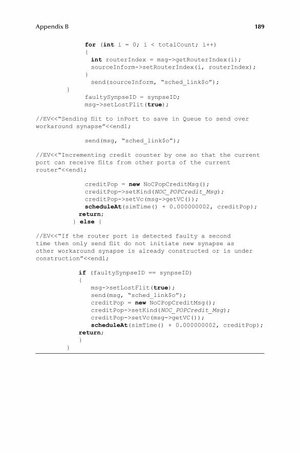
189Appendix B
for (int i = 0; i < totalCount; i++) { int routerIndex = msg->getRouterIndex(i); sourceInform->setRouterIndex(i, routerIndex); } send(sourceInform, “sched_link$o”); } faultySynpseID = synpseID; msg->setLostFlit(true);
//EV<<“Sending flit to inPort to save in Queue to send over workaround synapse”<<endl;
send(msg, “sched_link$o”);
//EV<<“Incrementing credit counter by one so that the current port can receive flits from other ports of the current router”<<endl;
creditPop = new NoCPopCreditMsg(); creditPop->setKind(NOC_POPCredit_Msg); creditPop->setVc(msg->getVC()); scheduleAt(simTime() + 0.000000002, creditPop); return; } else {
//EV<<“If the router port is detected faulty a second time then only send flit do not initiate new synapse as other workaround synapse is already constructed or is under construction”<<endl;
if (faultySynpseID == synpseID) { msg->setLostFlit(true); send(msg, “sched_link$o”); creditPop = new NoCPopCreditMsg(); creditPop->setKind(NOC_POPCredit_Msg); creditPop->setVc(msg->getVC()); scheduleAt(simTime() + 0.000000002, creditPop); return; } }

191
Index
A
accepted traffic (flit/cycle/node), 103Advanced Microcontroller Bus Architecture
(AMBA), 30algorithm 1, 72algorithm 2, 73algorithm 3, 74ant colony optimization (ACO), 49area and power consumption, 33artificial bee colony (ABC) algorithm, 50artificial immune system, 49asynchronous, 21, 22, 23, 32, 90, 109, 116, 131,
134, 136, 146autonomic network on chip using the biological
immune system, 52autonomous error tolerant (AET) architecture,
52
B
bandwidth, 1, 4, 5, 6, 9, 10, 13, 14, 20, 22, 24, 30, 34, 35, 36, 37, 59, 64, 79, 81, 84, 88, 89, 90, 91, 92, 94, 96, 97, 98, 99, 106, 107, 109, 110, 118, 119, 125, 132, 149, 152, 158, 162, 163, 175
bat algorithm (BA), 51BE, 7, 36, 37, 38, 56, 74, 75, 76, 77, 84, 85, 86,
88, 91, 94, 97, 98, 99, 100, 101, 102, 103, 104, 105, 106, 107, 110, 114, 116, 117, 118, 120, 121, 124, 126, 127, 134, 138, 144, 145, 146, 150, 155, 158
best effort, 6, 36, 56, 91, 110bio-inspired, 4, 6, 7, 38, 49, 50, 51, 52, 53, 55, 56,
57, 59, 60, 62, 64, 72, 73, 74, 82, 84, 86, 87, 89, 90, 91, 94, 95, 96, 97, 98, 99, 100, 101, 103, 105, 106, 109, 110, 111, 185
bio-inspired online fault detection in the NoC interconnect, 52
bio-inspired self-aware NoC fault-tolerant routing algorithm, 52
biological brain characteristics, 55brain, 4, 38, 51, 52, 55, 56, 57, 109broadcast communication, 28, 35buffering mechanisms, 28buffer management techniques, 19bus, 1, 29, 30, 31, 32, 33, 34, 35, 109, 114, 115,
123, 137, 141, 149, 150, 153, 154, 155, 156, 157, 161, 162, 163, 165, 166, 167
C
cat swarm optimization, 50channel, 9, 10, 11, 16, 17, 19, 20, 22, 29, 34, 35,
36, 37, 76, 79, 81, 82, 83, 84, 86, 89, 97, 104, 110, 117, 120, 123, 126, 128, 136, 140, 143, 145, 148, 151, 152, 153, 156, 158, 160, 161, 162, 163, 164, 165, 166, 169, 173
circuit switching, 9, 10, 13, 17, 110, 114, 115, 116, 117, 119, 124, 128, 129, 130, 131, 132, 134, 136, 139
clocking mechanism, 21, 32, 34, 35, 114cobweb, 51combined BE-GT, 7, 37, 38, 74, 84, 85, 88, 91,
98, 99, 100, 101, 102, 103, 104, 105, 106, 107, 110
congestion, 1, 2, 5, 11, 13, 14, 15, 19, 24, 25, 26, 29, 34, 35, 76, 88, 109, 118, 119
connectionless mechanism, 7connection-oriented, 5, 6, 9, 10, 13, 100connection-oriented stochastic routing, 5, 13connection type, 26, 35, 114contention free routing, 20, 81core, 1, 6, 31, 34, 62, 67, 74, 83, 88, 114, 117, 118,
120, 132, 133, 135, 139, 141, 146, 159, 163COSR, 5, 13credit-based flow control, 6, 7, 75, 110, 123, 141credit based technique, 19crossbar, 1, 24, 25, 62, 109, 114, 117, 118, 119,
122, 123, 124, 125, 127, 129, 131, 132, 133, 138, 139, 144, 169
cuckoo search (CS), 50cuttlefish algorithm (CFA), 51
D
data communications, 1, 109deadlock, 4, 5, 11, 12, 13, 14, 15, 16, 17, 18, 20,
34, 76, 83, 88, 127, 145destination, 1, 2, 3, 6, 9, 10, 11, 12, 13, 14, 15, 16,
18, 19, 20, 23, 24, 26, 27, 28, 29, 34, 35, 36, 52, 57, 59, 64, 65, 67, 68, 69, 70, 71, 73, 74, 75, 76, 77, 80, 84, 85, 86, 87, 90, 92, 93, 94, 98, 99, 102, 103, 105, 109, 110, 154
deterministic, 3, 4, 5, 6, 11, 12, 17, 38, 99, 101, 109, 114, 115, 116, 118, 119, 120, 121, 123, 125, 126, 127, 128, 129, 130, 134
devices, 1, 2, 21, 22, 30, 33, 90, 109dimension order routing, 12, 122

192 Index
directed flooding, 13DOR, 12, 15
E
end-to-end latency, 4, 98, 124, 135, 165epidemic spreading, 49
F
fat tree, 24, 35, 114, 117, 120, 128, 134, 137, 159faults, 1, 2, 4, 15, 17, 38, 51, 52, 57, 58, 59, 72, 74,
75, 79, 89, 90, 92, 94, 95, 96, 97, 98, 99, 100, 101, 102, 103, 104, 105, 106, 109, 110, 148, 159, 171, 173
fault tolerance, 1, 2, 4, 5, 12, 13, 15, 17, 24, 35, 38, 71, 109, 148, 152, 165
fault-tolerant, 1, 2, 4, 5, 6, 7, 11, 12, 13, 14, 15, 17, 38, 52, 55, 56, 57, 89, 100, 101, 103, 104, 105, 106, 109, 110, 185
fault-tolerant NoC using biological brain techniques, 52
firefly algorithm, 49flits, 5, 76, 77, 80, 85, 155, 160, 186flit size, 34, 35, 91, 148, 151, 153, 161, 163, 165,
166, 169flow control technique, 91flower pollination algorithm (FPA), 50force-directed wormhole routing, 5, 14framework, 7, 59, 89, 90, 91, 123frequency and technology, 32fully adaptive, 3, 4, 5, 6, 11, 14, 15, 38, 109,
143, 171future work, 109, 110
G
globally asynchronous and locally synchronous, 21
GT, 7, 36, 37, 38, 56, 74, 75, 79, 84, 85, 86, 88, 91, 97, 98, 99, 100, 101, 102, 103, 104, 105, 106, 107, 110, 116, 124, 136, 145, 146, 158
guaranteed throughput, 6, 7, 36, 56, 91, 110
H
Harris hawks optimization (HHO), 51head of line, 29, 79, 110heterochronous, 21, 23, 32hierarchical-routing-table-based FTDR
algorithm, 15
I
implementation platforms, 28injection rate, 9, 89, 90, 91, 97, 99, 100, 106, 127,
128, 131, 138, 139, 141, 142, 145, 170, 172
inPort, 59, 60, 61, 62, 64, 71, 72, 73, 74, 75, 76, 79, 83, 84, 85, 86, 155, 185, 187, 188, 189
input queue, 29, 148, 149, 150, 151, 158, 159, 166, 168, 169, 170, 172
interconnect, 1, 3, 6, 11, 20, 21, 22, 25, 29, 30, 34, 35, 38, 52, 57, 58, 59, 60, 64, 67, 68, 70, 71, 72, 73, 74, 75, 78, 81, 88, 89, 91, 94, 95, 102, 103, 109, 110, 114, 117, 123, 127, 128, 130, 144, 148, 151, 158, 160, 164, 171, 172, 186
Internet Protocol (IP), 1
K
killer whale algorithm (KWA), 51
L
latency, 1, 4, 5, 11, 12, 15, 17, 18, 20, 22, 24, 25, 26, 28, 29, 34, 35, 36, 51, 53, 59, 90, 91, 92, 93, 94, 95, 96, 97, 98, 99, 100, 107, 110, 114, 115, 116, 117, 118, 119, 120, 122, 123, 124, 126 – 174
link, 9, 10, 11, 15, 19, 20, 21, 24, 25, 29, 59, 60, 72, 73, 74, 76, 79, 81, 84, 110, 114, 186
livelock, 5, 11, 13, 16, 17
M
mesh, 1, 24, 25, 28, 34, 51, 74, 90, 91, 114mesochronous, 21, 23, 32, 116message, 1, 10, 15, 17, 26, 27, 32, 35, 51, 77, 86,
114, 185minimal path routing, 12multicast connections, 27
N
nanotechnology, 2narrowcast, 26, 27Network on Chip (NoC), 1, 2, 9, 26, 35, 51, 56,
89, 90, 109, 124NI, 1, 11, 20, 21, 29, 31, 66, 75N-random walk, 5, 13
O
octagon, 24, 25, 115, 129, 137, 149, 166on-chip communication, 1, 109Open Core Protocol (OCP), 31open-source, 25, 26OutPortCalc, 59, 65, 82output queue, 29, 148, 150, 151, 152
P
packet, 1, 4, 6, 9 – 21, 28, 34 – 37, 52, 58, 59, 60, 61, 62, 64 – 86, 88 – 92, 94, 97, 99, 100, 106, 109 – 111, 114

193Index
partial adaptive, 3 – 6, 11, 15, 16, 17, 38, 109performance evaluation parameters, 91PEs, 1, 6, 9, 10, 11, 14, 19, 20, 21, 22, 24, 25, 26,
27, 29, 30, 31, 36, 38, 74, 75, 106, 109, 110, 146planar adaptive routing algorithm, 16plesichronous, 21, 23, 32, 118power, 5, 13, 14, 15, 16, 17, 19, 20, 21, 22, 24, 28,
30, 33, 34, 35, 53, 88, 114processing elements, 1, 9, 52, 109
Q
quality of services (QoS), 110
R
reliable, 1, 3, 6, 11, 19, 52, 88, 133, 164research framework, design and parameters, 89resources, 1, 2, 3, 9, 11, 12, 13, 17, 20, 36, 75, 97,
102, 109, 110, 119, 140ring, 1, 4, 25, 115, 119, 131, 134, 135, 140, 145,
153, 169round-robin arbitration, 10, 114, 117, 121, 122,
123, 137, 146router ports and bus width, 34routers, 1, 2, 5, 6, 9, 10, 14 – 22, 24, 25, 29, 36, 52,
59, 61, 62, 64, 65, 67, 68, 73, 74, 75, 76, 77, 79, 80, 81, 85, 88, 91, 94, 106, 109, 110, 111, 123, 124, 125, 128, 144, 167
routing algorithm, 1 – 7, 10 – 17, 24, 24, 34, 35, 38, 51, 52, 67, 68, 77, 91, 94, 96, 98, 104, 109, 111, 164
routing table, 4, 5, 6, 14, 15, 16, 88, 128R-Software, 90
S
saturation point, 35, 93, 94, 103, 105, 106, 110, 149, 155, 159, 166, 167, 168, 169, 170, 173, 174
scalable bio-inspired fault detection unit, 51scheduler, 29, 59, 60, 61, 62, 64, 71, 72, 73, 74,
75, 76, 79, 81, 82, 83, 84, 85, 86, 186self-adapt, 6, 52, 56self-heal, 6, 38, 52, 56self-optimize, 6services, 6, 9, 14, 36, 37, 38, 56, 74, 75, 76, 79,
84, 85, 86, 88, 91, 97, 103, 104, 106, 107, 110, 118, 124, 156
shared virtual channel control technique, 19, 20simple connection, 26source routing, 5, 11, 14, 124
spidergon, 24, 25, 121, 129, 132, 139, 153, 160SpiNNaker communication, 52sprouting, 6, 38, 52, 56, 57, 58, 59, 72, 73, 91, 97,
98, 99, 100, 101, 102, 103, 104, 105, 109, 188star, 23, 24, 115, 118, 122, 124, 126, 129, 139,
144, 146, 152, 174stochastic, 3, 4, 5, 6, 11, 13, 15, 17, 38, 109store and forward, 17, 18, 119, 131subnets, 24, 25, 128, 141summary, 7, 38, 88, 106swarm intelligence algorithms (SIA), 49synaptogenesis, 6, 38, 52, 56, 57, 59, 72, 91, 94,
98, 101, 102, 103, 104, 105, 109, 185synchronous, 21, 22, 31, 32, 34, 53, 90, 109, 114
T
throughput, 4, 6, 7, 9, 10, 11, 12, 14, 17, 20, 24, 34, 35, 36, 51, 53, 56, 59, 81, 82, 90, 91, 93, 95, 96, 97, 101, 102, 103, 106, 107, 110, 114
time division multiplexing (TDM), 16, 79, 81, 83, 87, 91, 97, 98, 99, 100, 101, 102, 106, 110, 114
topology, 1, 24, 25, 34, 35, 51, 74, 90, 91, 114torus, 1, 3, 24, 28, 51, 114
V
virtual channels, 9, 10, 11, 16, 17, 37, 76, 79, 81, 83, 86, 110, 117
virtual cut through, 17, 18, 125, 129, 131, 133, 134, 140, 142
virtual output queue, 29, 165, 172Virtual Socket Interface Alliance (VSIA), 32
W
west first, negative first, north last, south last routing algorithms, 16
wormhole switching, 10, 14, 17, 18, 34, 89, 90, 91, 114
X
XY, 5, 12, 91, 96, 98, 99, 101, 102, 105, 117, 118
Y
year of proposal, 34
Z
ZYX, 5, 12