Embed Size (px)
Citation preview

BIM for Construction:
Project Pursuit and Logistics John Arnaud – The Whiting-Turner Contracting Company
CR5261-V
Autodesk has developed a suite of Building Information Modeling (BIM) programs that are useful throughout the AEC industry during all phases of a project. For construction entities, a critical phase of a project is pursuit and award—without it there is no project. During this phase, a logistical building information model can be extremely useful for developing and conveying a thorough understanding of a project as well as the ability to complete it. This is also a time when project information, up to and including a BIM model, is in the early stages of development and can be difficult to obtain. This class will look at the process of evaluating resources and modeling strategies to efficiently model a project to convey critical information and to develop presentation quality exhibits.
Learning Objectives At the end of this class, you will be able to:
Determine the most effective way to utilize available resources to create a logistical presentation model
Incorporate the phasing of a project into a model
Efficiently utilize program tools for creation of a detailed building model
Develop presentation quality exhibits from a model
About the Speaker
John Arnaud is a Project Engineer and Virtual Design and Construction Coordinator with The Whiting-
Turner Contracting Company, a large general contractor that is based out of Baltimore, Maryland and
has regional offices throughout the country. He has worked on numerous project pursuits,
preconstruction planning, and on developing the company’s VDC training program. John works in
Whiting-Turner's regional office in Raleigh, NC. Before his time with Whiting-Turner, John managed
production of the Revit model and documentation that was then used to coordinate construction for the
Solar Homestead, Appalachian State University’s entry in the 2011 DOE Solar Decathlon. The entry
placed 2nd in the architecture contest and received the People’s Choice Award. As a student at
Appalachian State University John educated peers by teaching Revit skills both in classes and individual
settings, his efforts earned him the Building Science Program’s Outstanding Student Award.
Email: [email protected]

BIM for Construction: Project Pursuit and Logistics
2
Introduction Autodesk has developed a suite of Building Information Modeling (BIM) programs that are useful throughout the AEC industry during all phases of a project. For construction entities, a critical phase of a project is pursuit and award—without it there is no project. During this phase, a logistical building information model can be extremely useful for developing and conveying a thorough understanding of a project as well as the ability to complete it. This is also a time when project information, up to and including a BIM model, is in the early stages of development and can be difficult to obtain. This class will look at the process of evaluating resources and modeling strategies to efficiently model a project to convey critical information and develop presentation quality exhibits.
The purpose of this class is to demonstrate how Autodesk Revit Architecture can be utilized to produce a model that conveys a thorough understanding of and the ability to complete a project.
At the end of this class, you will be able to:
Determine the most effective way to utilize resources to create a model
Incorporate the phasing of a project into a model
Efficiently utilize program tools for model creation
Develop presentation quality exhibits
The class will be broken down into five segments, these include:
Module 1: Introduction
Module 2: Developing a Site Model
Module 3: Model and Project Phasing
Module 4: Creating a Detailed Building Model
Module 5: Producing Presentation Quality Exhibits

BIM for Construction: Project Pursuit and Logistics
3
Planning for Your Pursuit
Before you begin modeling there is a considerable amount of planning that has to be done. You along
with your team need to evaluate the project, the project site, the logistical challenges of the project, as
well as, what you want present with the model, and how you want to present it.
From there you can begin researching your available resources. Are models available from the architect
or engineers? Acquisition of a developed architectural and site model can prove to be extremely
valuable. Developed models can increase the accuracy of your model and save you the time of actually
having to create one.
Often time site information is available through a local Geographical Information Survey (GIS), also tools like Google Maps and Google Earth can give you a great feel of the area. BING Maps also offers some pretty cool birds’ eye views of most locations. If a building model is not available you’ll be creating one, whether it is a detailed depiction or a general mass to serve as a place holder.
You should take your time to research the building you will be depicting, have a general idea of its size, structure type and grid layout, know or have the resources to complete a fairly accurate (just enough to get by) model of the building skin.
Also important, is integration of the modeling effort into the project proposal or presentation. You will need to know what kind of deliverables are required from you team and how to present your work in order to most effectively convey your teams understanding of and ability to complete the project.

BIM for Construction: Project Pursuit and Logistics
4
Developing a Site Model
In this Module we’ll look at:
Effectively utilizing available resources
Creating a detailed site model
Using Autodesk Revit Architecture’s site modeling tools
Your objectives when modeling the site should be to show as much detail as necessary in order to
demonstrate your considerations. You can start by retrieving site info from a couple places,
Google Earth/Maps
o Offers useful street view and aerial views
Bing Maps
o Offers useful bird’s eye and aerial views
SketchUp
o Topographical contours can be imported and exported as .dwg files
County GIS Maps
o Image and .dwg files are often available
Project Documentation
o Available models, drawings, narratives, and specifications
Site Visits
o The most effective way to evaluate a site is by actually visiting it!
These tools along with an understanding of your project can be used to determine:
How much of site do you want to show?
What type of site work is necessary and does the site need to be phased?
Is a model with a ‘featureless’ or flat topography acceptable?
Want are there key features of the site?
What details will be necessary to model?
Creating a Simple Site Model
A simple model of an existing site can be created from scratch in Revit. This can be easily done by
working from a background image.
To do this, obtain an image of your site from one of the previously mentioned sources.
Import the image to your Site Plan View.
Insert Panel > Import Image

BIM for Construction: Project Pursuit and Logistics
5
*Note: Revit allows you to import Bitmap, Jpeg, PNG, and Tiff image files.
Scale your drawing! It’s frustrating to realize you have forgotten this step once you have begun modeling.
You will need something to scale the drawing to. Most parking spaces are about 9’ x 18’ this or other
standard dimensions can be used to scale an aerial image. Drawings and construction documents can
be easily scaled from a dimension or a drawing scale.
Select the Create Topography tool from the Massing & Site Panel then use Place Points to outline your
desired site.
Set points to an elevation of 0’ 0” then create the topography.
In order to see your imported image you will need to turn the Visual Style to wire frame.
I like to examine my work intermittently in the 3D View with my Graphic Display set to Shaded. Your site
should appear as a simple flat surface.
Sub Regions
In the Site Plan View select the Sub Region tool from the Massing and Site Panel and sketch a Sub
Region per the imported image.

BIM for Construction: Project Pursuit and Logistics
6
Create the pond and two parking areas, each will have to be individual Sub Regions.
As you create Sub Regions assign materials to them, and as you select materials be sure to set their
graphic appearance, render appearance, and give them a descriptive name.
*Note: Graphic Properties adjust the appearance of the material on your screen and in documentation.
Appearance Properties adjust the appearance of the material in rendered images.
It is important to specify both because when you go to render a view of a completed project,
having previously assigned an appearance to each material will save you a significant amount of
work. We’ll look at rendering in the fifth module of this class, Presentation Quality Exhibits.
Simple Site Features
Basic topographic features can be created using the Place Point tool
For example the pond
In the Site Plan View, Edit Topography place 0’-0” points at extents of pond, then place -4’ points along
the edges (closely together for a steep bank and farther apart for mellow sloped bank), then create the
topography.
0’ 0”
-4’ 0”

BIM for Construction: Project Pursuit and Logistics
7
Your 3D model should look like this.
This method can be can be used to create simple streams, rivers, hills, and similar site features.
Creating a Site Model Using an Import
Revit can create sites based on 3D contour data from DWG, DXF, and DGN file imports.
This can be extremely useful when modeling complex topography’s.
For this method we will start off by working in Trimble SketchUp Pro
You will need SketchUp Pro, because it allows you to export your work as a DWG file.
Open the Geo Location tool then find and select your site.

BIM for Construction: Project Pursuit and Logistics
8
The import is placed to scale, so no scaling is necessary in SketchUp or later in Revit.
You will want to set your style to X-Ray, the SketchUp equivalent of Revit’s Wireframe Visual Style, then
use SketchUp’s simplified drawing tools to draw site elements as desired.
When completed export your work. File > Export > 3D Model > DWG
In a blank Revit Project select Import CAD from the Insert Panel
Browse and select your file, the default import settings will work fine and preserve the scale as set by
SketchUp.
*Note: If you are importing site data that you have acquired from somewhere other than SketchUp you will
use this same process. If you are working from a file you retrieved from a local GIS it should be noted
that topographic CAD files are often very large, you may want to consider trimming them to size in
Autodesk AutoCAD before importing into Revit.

BIM for Construction: Project Pursuit and Logistics
9
The Import will be visible in the 3D View. In the Massing & Site Panel select Topo Surface then select the
Create from Import then Select the Import Instance tool.
Select the layer you want to create the topographic surface from, if you are importing from SketchUp the
layer will be called (google_earth_terrain), if you are import form somewhere else this will be the layer that
contains the site contours.
This creates a very complex surface, so you can use the Simplify Site tool and simplify to 5’. Then create
the surface.
You can now Hide or Delete the DWG Import.
From here you can create Sub Regions and edit your site as necessary.
When sketching your Sub Regions you can use the pick lines tool to pick the lines that were created in
your import if it has any.
Adding Detail Site Components
Detailed Site Components can be easily placed using the components provided by Revit.
In the Architecture Panel select Place Component. In the properties menu you will see several preloaded
components including parking spaces and deciduous trees. If you are looking for other components you
can load others into your model using the Load Family tool.

BIM for Construction: Project Pursuit and Logistics
10
Start with parking spaces, Place and Copy and adjust the items as necessary. Vegetation can be Placed
the same way.
For areas of with dense vegetation Place Planting heavy in one area then Copy that area throughout.
BIM for Construction: Project Pursuit and Logistics
11
Model and Project Phasing
In this module we’ll look at:
- Setting up Autodesk Revit Architecture’s phasing tools
- Applying phasing to the site model we just created
- And how to model within Revit’s phases
As you have developed a logistics plan with your team it will likely break the project down into phases.
Revit’s phasing tool allows you to incorporate these phases into your model. It is best to start with a
general idea of what your phases will be and then enter them into your project using the Phasing
Manager Tool, keep in mind that you can (and probably will) be able to insert additional phases as
needed.
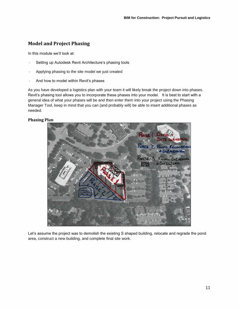
Phasing Plan
Let’s assume the project was to demolish the existing S shaped building, relocate and regrade the pond
area, construct a new building, and complete final site work.

BIM for Construction: Project Pursuit and Logistics
12
In order to best convey the intent sketched by the ‘Project Team’ I would phase the project like this.
Existing Site – Showing the site before the project began
Demolition – Showing the removal of the existing structure
Site Work 1 – Clearing the site where the demolished structure was
Site Work 2 – Showing the relocation and regarding of the pond
Foundations
Structure 1
Structure 2
Skin
Site Work 3 – Showing final grading and site work
Complete – Showing the finished project
*Note: You might notice there is no phase in which I show, mention, or plan on modeling the interior
portion of the building. This is because for the purpose of this class and project we will not be
showing any interior work or generating any interior images. If this is something you want to show
I recommend completing a model of the building structure and exterior skin, resaving as a new
project, then developing the building’s interior; however there are a number of ways to go about it
depending on you preferences.
Preparing Your Site for Phasing
If after evaluating the project and the impact of the site work you have decided it is necessary to show
phasing of the actual project site, you will need to create multiple sites, one per each phase of site work.
This is the easiest way to phase site work in Revit. This is because Topographies and Sub Regions have
to be created in the same phase as their surrounding site, or ‘created in the same phase as their host.’
All showing respective parts of the new structure

BIM for Construction: Project Pursuit and Logistics
13
Copy the site in one direction; you will want as many sites as you have phases of site work on your
project. Use a memorable distance to do this.
Using the tools we have discussed modify the subsequent sites to be as you need for subsequent
phases. I modified mine to look like this.

BIM for Construction: Project Pursuit and Logistics
14
Establishing Model Phases
Open the Phases Manager in the Manage Panel and create the phases we previously discussed then
click OK to apply and close the manager.
If you look at the Phasing section of the 3D View properties you will find all of the phases that you just
created.
Set the Phase Filter to ‘Show All’
If you select an object and view its properties you can adjust; the phase that it
is created (or the phase that it appears in the model), and the phase that it is
demolished in (the phase that it disappears from the model).
*Note: It is important to be able to differentiate between ‘View Properties’ and
‘Element Properties’; if nothing is selected the properties displayed will
be that of the view. If an element is selected the properties shown will
be those of the selected element. In the View Properties we can edit
the Phase Filter and Current Phase. In Element Properties we can
edit the phases that elements are created and demolished in.
Assigning Phasing to Your Site
Set the first site to be created in the Existing Site phase and demolished in
Site Work 1. Assign the second site to be created in Site Work 1 and
demolished in Site Work 2. Set the third site to be created in Site Work 2 and
demolished in Site Work 3. Finally, set the fourth site to be created in Site
Work 3 and demolished in Site Work 4.

BIM for Construction: Project Pursuit and Logistics
15
If you set your phase filter to ‘Show Complete’ and your current Phase to Existing Site you can see only
the Existing Site we created. If you change the current phase to Site Work 1, you will see the second,
Site Work 2 to see the third, Site Work 3 to see the completed site.
Next, set the site elements to be created in the Existing phase and to remain throughout the project, or to
‘Never’ be demolished.
Set the Phase Filter in your View Properties to None, and then move each site to the same location as
the original, by the increments of 1000’ you used earlier. This will allow you to create the appearance of
the site being updated per phase, when what you are really doing is just showing a whole new site at
each phase.
Once the sites are stacked set the Phase Filter to Show complete. You will leave it set this way for most
of the remainder of the project.
You can now cycle through the Current Phases in the view properties to see the evolution of our site
throughout the project.
*Note: From this point forward it is important to model in the phase that you intend for the elements you
are modeling to be created. While you can edit the phase elements are created, it is most efficient
to avoid having to go back and do this.
Modeling within Phases
Start by modeling the existing building on the site.
In your Site Plan View set Phase Filter to Show Complete and Current Phase to Existing.
Since the details of the existing building are not critical for the purpose of this project create the existing
structure as a Component Modeled-In-Place.
In your Architecture Panel select Model Component In-Place then choose to model an Extrusion.
Draw the footprint of the building, check complete, and then assign the extrusion a height of 45’
(approximate height of existing building.)
Before you finish the component take a look at the 3D View to ensure you have created what you
intended and assign a material, I recommend a frosted or mirrored glass. This way we show that there is
an existing building and the general massing of the building, but do not have to model the whole building
in detail. Then finish the component.
*Note: Remember to create a material with graphic and appearance properties specific to the purpose of
the material.
Set the Phase Demolished for the component, for the case of this building it will be demolished in the
‘Demolition’ phase of the project.
*Note: If there were a number of surrounding buildings I would recommend creating them the same way
you created the existing structure. Unless the existing buildings are going to be demolished during

BIM for Construction: Project Pursuit and Logistics
16
your project, they will be created in the ‘Existing Phase’ and their demolish phase would be
‘Never.’
Model In-Place Tips
When modeling building masses using the Model in Place tools some helpful tips include:
If you have imported a DWG file that shows building footprints (either from SketchUp or
elsewhere) you can use the Pick Line tool to create an accurate footprint for an Extrusion.
Gable roofs are easily created using the Sweep form.
While Sweeps easily create components like gable roofs, extrusions are easily manipulated with
Shape Handles and without having to Edit them In-Place
If a building is composed of multiple modeled components, join them all before assigning a
material. This allows you to assign a material once to the whole system rather than individually to
each part.
In this module we discussed setting up Autodesk Revit’s phasing tools, applying phasing to a site model,
and how to model within Revit’s phases.

BIM for Construction: Project Pursuit and Logistics
17
Creating a Detailed Building Model
In this Module we’ll look at
- Creating a detailed building model
- Efficiently using Autodesk Revit Architecture’s modeling tools
Once you have your site created and your project phasing defined you’ll finally get to start modeling a
building! If a model is available you can link or import it, but remember you’ll have to assign elements to
any phasing scheme you are following.
When creating a model do so in the order build, from the ground up. Creating and following a project grid
will allow you to quickly create columns and beams. Revit’s clipboard enables you to quickly model entire
floors. As you model remember to model in the phases that elements are created and to assign material
properties to elements.
Having a Plan When you are modeling it is always important to have a plan. Whether your plan it is to work from
drawings, sketches, or something you and your team have drawn up.
In the resources for this course you will find a set of reference drawings that can be used to assist with
the modeling for this class.

BIM for Construction: Project Pursuit and Logistics
18
Obviously these don’t provide full construction details, but they give enough info to make assumptions
about the structure and skin of the building.
Establishing the Project Grid
Start in the phased site model created in the previous module.
Go to the Site Plan View.
The first thing you will want to do is hide or delete the image of the site that we imported earlier.
Set the Current Phase to Foundations and the Phase filter to See Complete.
Import the floor plan from the reference documents.
*Note: Revit allows you to import only certain image files and does not allow PDF’s. Construction
drawings are most often provided in PDF format. If you want to work from a construction drawing
programs like Adobe Acrobat or Revu Bluebeam allow you to save a PDF as one of the image file
types that Revit will allow you to import.
Once Imported, Scale the image to the correct size based on a known dimension. Then move the
drawing to your buildings correct location.
Then place Grid Lines, you can find these in the Structure Panel.
*Note: If you do not have any documentation of where the gridlines are you can make assumptions,
remember this model will be used primarily for visual aid so the structure of the building only has to
be correct at a glance. I find creating the structure per gridlines to be more efficient than working
without a guide; if you disagree you can skip this step and begin creating your levels.
Once you have created your grid, you’ll want to create levels for each floor of your building.
To do, so view your project in one of the Elevation Views and set your View Properties to View Complete
in the Demolition phase.
BIM for Construction: Project Pursuit and Logistics
19
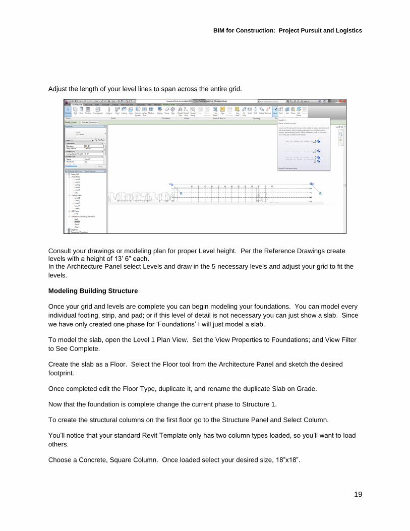
Adjust the length of your level lines to span across the entire grid.
Consult your drawings or modeling plan for proper Level height. Per the Reference Drawings create levels with a height of 13’ 6” each. In the Architecture Panel select Levels and draw in the 5 necessary levels and adjust your grid to fit the
levels.
Modeling Building Structure
Once your grid and levels are complete you can begin modeling your foundations. You can model every
individual footing, strip, and pad; or if this level of detail is not necessary you can just show a slab. Since
we have only created one phase for ‘Foundations’ I will just model a slab.
To model the slab, open the Level 1 Plan View. Set the View Properties to Foundations; and View Filter
to See Complete.
Create the slab as a Floor. Select the Floor tool from the Architecture Panel and sketch the desired
footprint.
Once completed edit the Floor Type, duplicate it, and rename the duplicate Slab on Grade.
Now that the foundation is complete change the current phase to Structure 1.
To create the structural columns on the first floor go to the Structure Panel and Select Column.
You’ll notice that your standard Revit Template only has two column types loaded, so you’ll want to load
others.
Choose a Concrete, Square Column. Once loaded select your desired size, 18”x18”.

BIM for Construction: Project Pursuit and Logistics
20
To place the columns use the Place at Grids tool, this is why we took the time to create the grid pattern
for the building.
Select the tool and then select the grid intersections that you want to create columns at (all of them for
this building). Then check complete to place the columns.
You can view the project in the 3D view to check your progress, be sure to set the appropriate phase.
To create structural beams go to your Level 2 View and set the phase filter appropriately. Then in the
Structure Panel select Beams. Again, you will have to load the appropriate Family, Beams are in the
Structural Framing folder. Choose a Rectangular Concrete Beam.
Before you place the beams set the beam type, choose 12”x24” beams and set their reference level to
Level 2 and set Z Direction Justification to Top of Beam.
This sets the top of the beam to bottom to align with the Second Level.
To place the Beam’s use the place by grid tool. Select the tool, then select the gridlines that you want to
place beams on. Choose all of the exterior grid lines and then all of the horizontal or East West gridlines.
Check complete to create the beams.
You can double check your work by viewing the 3D View.
The next step is to create an elevated slab for the second floor.

BIM for Construction: Project Pursuit and Logistics
21
Return to your Level 2 Floor Plan View and select Structural Floor from the Architecture Panel. Sketch
the footprint. Use the pick line tool to select the edges of the footprint of the Slab on Grade below. Then
create the floor.
Once completed change the floor type to 3” LW Concrete on 2” Metal Deck, then duplicate the floor type
and rename it Elevated Slab.
If you view your project in 3D view you’ll now see that you have created one floor’s worth of structure. To
create the remaining floors save yourself some effort by copying the floor you have already created.
In 3D view select the columns, beams, and elevated slab that are already created (but not the Slab on Grade). With these elements selected choose Copy to Clipboard from the clipboard tools in the Modify Panel. Then choose the Paste Aligned to Selected Levels clipboard option.
Then Paste to Level 3.
In order to have the rest of the structure created in the Structure 2 phase, change the Current Phase in
your view properties to Structure 2.
Now continue pasting to Selected Level with Level 4, and the Level 5.
There is no need to recopy as you already have everything saved to our clipboard.
The structure of the model is now complete.

BIM for Construction: Project Pursuit and Logistics
22
Modeling Exterior Skin
Let’s look at the detailing of the building skin.
Looking at the Reference Documents we can see that the exterior of the building is brick with areas of
storefront and curtain wall.
In the Level 1 Floor Plan change the View Properties Current Phase to Skin.
In the Architecture Panel select Architectural Wall. Select the wall type Brick on Metal Stud, then click
Edit Type Duplicate the type and name it Exterior Brick Wall.
Then draw the wall. When drawing walls always try to draw in a clockwise direction, this way the interior
and exterior of the wall are always properly orientated.
When I draw walls I typically draw them wide of where I want the final location of the wall to be. I then
use the Align tool to relocate the walls to exactly where I want them.
Select the Align tool from the Modify Panel, then select the face you want to align to then select what you
want to align to it and repeat this for each wall.

BIM for Construction: Project Pursuit and Logistics
23
Once you have aligned the surrounding walls you can simply drag the diagonal wall to the desired
location.
Go to your 3D View and adjust the Current Phase to Skin, this will allow you to see your work.
You can use the Shape Handle to drag a wall to your desired height. Add a foot to the height of the wall
to create a parapet. You can then use the match type properties to set this height to the rest of your
walls. Select the tool from the Clipboard tools in your Modify Panel and click the wall with the properties
you want to apply to others and then click the remaining walls one at a time.
To allow easy viewing of your model for the next couple steps activate the Section Box. There is a check
box to activate this tool in the View Properties. Once you have activated the Section Box use the shape
handles to adjust its size to just larger than the building.
Next, create voids in the skin of the building where the different glazing will go using the Edit Profile tool.
The tool appears in the Modify Panel when you select walls.
Once you are editing the profile of a wall, get a direct view of that wall by selecting the respective side of
the view cube.
The Reference Drawings show long expanses of glass along the East wall.

BIM for Construction: Project Pursuit and Logistics
24
Sketch these by creating a rectangle the size of the floor opening. Then use the offset tool to make it the
desired size. 3’ offset on the bottom, 2’ offset on the ends, and 1’ offset along the top. Rather than
resketching this opening, just copy it to each floor.
Then finish the profile. Take similar steps with the diagonal North East Wall. You can select the
corner of the View Cube for a direct view of this wall.
Then sketch the approximate opening per the Reference Drawings. Repeat this process for each wall.
To create Curtain Wall infill return to your Level 1 Floor Plan View.
Select Architectural Wall and one of the Curtain Wall Types, then Edit the Properties, Duplicate it, and
assign it a name. Then draw the Curtain wall in its location. Repeat this for each size opening.
*Note: Revit may inform you that walls are overlapping. Let Revit know we appreciate the heads up and
intend on handling the situation.

BIM for Construction: Project Pursuit and Logistics
25
Return to your 3D View and select each piece of glazing and use the Shape Handles to fit it exactly to its
opening.
You can use the Edit Properties tool to adjust the curtain panel type and mullions for the Curtain Wall you
have created in each location. I typically select a Glazed Curtain Panel and Fixed Number for mullions.
The possibilities for curtain walls are endless. If this is something you have interest in I’m sure there are
Autodesk University classes available, just checkout the Course Catalogue.
Once you have the Curtain wall adjusted per your liking, view the wall directly using the View Cube.
Select the Curtain Wall (you will know you have it selected when there is a dashed highlighted line around
the whole system.) Then copy the element to the other identical openings. (You may have to unconstrain
the copy.)

BIM for Construction: Project Pursuit and Logistics
26
Once you have filled in all the glazing you can take a ‘Big Picture’ look at your model and see you’ve got
a pretty complete building. If you flip through the current phases in your 3D View you can see the phases
of construction.
With the addition of a few logistical components and some rendering we have created a model that conveys our understanding of the project and will be of a quality that can be incorporated into a presentation and used in the pursuit of a project.
In this module we discussed how to efficiently use Autodesk Revit’s modeling tools to create a detailed
building model and do so within the phases we created earlier.

BIM for Construction: Project Pursuit and Logistics
27
Producing Presentation Quality Exhibits
In order to use our model to demonstrate a thorough understanding of a project it is essential to develop
materials of the highest quality. This can be done by exporting views and renderings. It is important to
show all the details and considerations taken by the project team. These include not only construction of
the building and development of the site, but placemen of trailers, fence, entrances storage areas and
other logistical components. Once all of these are incorporated in to the model and its phasing scheme
the rendering tool can be used to create high quality images.
Having a Plan
Just as when modeling the building and its construction, you will need to have a plan for your site
logistics.
Something like this should be developed with your project team. You can see where this team has
determined:
Construction Traffic Route
Material Storage
The Field Offices
Parking
Restrooms

BIM for Construction: Project Pursuit and Logistics
28
Dumpsters
Silt and Construction Fences
o In two phases – Demo and Construction
Tire Wash Station
We’re going to incorporate each of these elements into our model, when doing so we’re also going to take
consideration for which phase they will be placed on site and during which phase they be removed from
the site.
Incorporating Logistical Considerations
As we prepare to begin placing logistical components we’ll quickly realize we are missing two important
phases.
‘Mobilization’ and ‘Demobilization’
In the mobilization phase the team will place things like field offices, fencing, the tire wash station, and
other elements that are needed for work to begin.
In the Demobilization Phase these components will be removed, this will be just before completion of the
project.
Start with the Model we completed in Module 4.
To add the two Mobilization phases let’s return to our Phase Manager in the Manage Panel.
BIM for Construction: Project Pursuit and Logistics
29
Add our Mobilization phase before Demolition, select Demolition click Insert Before and name the phase
Mobilization. Then add our Demobilization phase just before Complete, select Complete and click Insert
Before.
Now that all phases are loaded, begin modeling the different components of our team’s logistics plan.
Let’s start with the fencing. Silt fence will need to be modeled around the entire site; silt fence can be
modeled as a low wall. Do this in 3D View, to get a floor plan type view of your model click the top of the
View Cube.
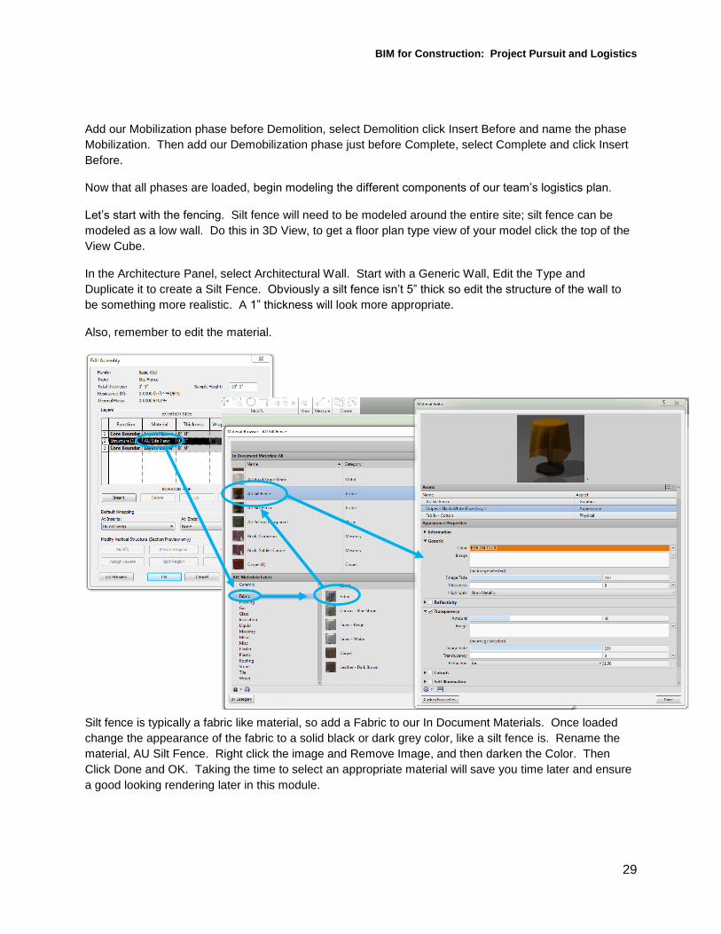
In the Architecture Panel, select Architectural Wall. Start with a Generic Wall, Edit the Type and
Duplicate it to create a Silt Fence. Obviously a silt fence isn’t 5” thick so edit the structure of the wall to
be something more realistic. A 1” thickness will look more appropriate.
Also, remember to edit the material.
Silt fence is typically a fabric like material, so add a Fabric to our In Document Materials. Once loaded
change the appearance of the fabric to a solid black or dark grey color, like a silt fence is. Rename the
material, AU Silt Fence. Right click the image and Remove Image, and then darken the Color. Then
Click Done and OK. Taking the time to select an appropriate material will save you time later and ensure
a good looking rendering later in this module.

BIM for Construction: Project Pursuit and Logistics
30
When drawing the Silt Fence remember that silt fences are rarely a straight line, they are often a series of
arches because they are attached on intervals to posts, so use your arch tool to draw it this way. Once
the silt fence is drawn adjust its height to about 3’ and set its phase created and phase demolished.
Select all of the Silt Fence. In element properties set the Top Constraint to Unconnected and the
Unconnected Height to 3’. Then set the Phase Created to Mobilization and Phase Demolished to
Demobilization.
Now the same way you created the silt fence create a site fence and a fence for the material storage
area.
View from the top using the View Cube
Go to the Architecture Panel, select Architectural Wall. Start with a Basic Wall, Edit the Type, Duplicate it
and Create a Site Fence. Set the Structure to 3” for this one, and edit the material. Create a material
similar to the silt fence, except we’ll make the site fence orange and give it some transparency. Select
the AU Silt Fence created earlier and duplicate it, then Rename it AU Site Fence. Set the Color to a
construction Orange color. Turn Transparency on to a lower percent, 30% or less.
Set the height before you draw this time. Make it an 8’ fence. Draw in the entire fence, as described by
the project team. Next, select the parts of the fence that we want created during mobilization and
demolished during demobilization.

BIM for Construction: Project Pursuit and Logistics
31
Next, Select and set the phasing for the parts of the fence you want created during Mobilization and
removed shortly after Demolition. You may have to split some walls, or lengths of fence to do this. To
split an element select it, the select the Split Element tool from the Modify Panel, click where you want to
split.
Next, repeat the process for the fencing you want to be created after Demolition and removed during
Demobilization.
Now you can click through the current phases to make sure you have your fencing properly phased.
Next, place other Logistical elements like the Field Offices, Restrooms, Tire Wash Station, and
Dumpsters. All of these elements that can be created a couple of ways, they can be Modeled In-Place as
components or they can be inserted as components.
For this course we are going to place them as components. Some components like this are built into
Revit and you can load them into your project by loading family then looking in the site component folder,
others are available through websites like Autodesk Seek (has a search bar in the Insert Panel) and Revit
City (www.revitcity.com), or you can create your own Families in all of your free time….
BIM for Construction: Project Pursuit and Logistics
32
In the project resources there are several components that are available for download. I have created
these items as components for previous projects and made them available as resources for this class. To
insert these components open your Insert Panel and click Load Family, then navigate to the location
where you have them saved and select them (you can select multiple) and click Open.
Now go to your Architecture Panel and click Place Component, place each component as desired. Some
components may have to be rotated and moved in order to be arranged per the logistics plan.
The remaining items are parking, material storage, and traffic route.
For all of these items I typically Model In-Place Components to represent them.
For parking and material storage I create transparent tinted boxes with text clarifying what the areas
represent, and the traffic arrows I typically model the arrows as In-Place Components and give them a
noticeable color.
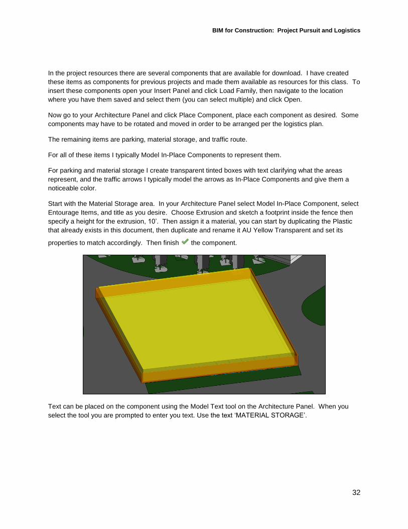
Start with the Material Storage area. In your Architecture Panel select Model In-Place Component, select
Entourage Items, and title as you desire. Choose Extrusion and sketch a footprint inside the fence then
specify a height for the extrusion, 10’. Then assign it a material, you can start by duplicating the Plastic
that already exists in this document, then duplicate and rename it AU Yellow Transparent and set its
properties to match accordingly. Then finish the component.
Text can be placed on the component using the Model Text tool on the Architecture Panel. When you
select the tool you are prompted to enter you text. Use the text ‘MATERIAL STORAGE’.

BIM for Construction: Project Pursuit and Logistics
33
Click OK and select the face you want to place text on.
To change the appearance of the text select Edit Type from the element properties menu of the text to
make it larger, 16’ text height and 2’ depth should be large enough. Then set the material of the text, a
white plastic should be perfect.
To create the parking area you can repeat all the steps you just went through or you can copy the
material storage area and modify it for its new purpose.
Do this by viewing the project from top (adjust on the View Cube). Select the box and text and copy them
from their current location to the parking area. Then rotate the box and text. Resize the box using the
Shape Handles. You can change the text by selecting it and clicking Edit Text in the Element Properties.
Change the text to ‘CONSTRUCTION PARKING’
To create traffic arrows model an in-place component. They will be an Entourage item as well, name
them Traffic Arrows. Model an Extrusion form and sketch the arrows as desired.
Once you have drawn one arrow copy and rotate it as needed. Create the extrusion and assign it a
height of about 4’. Then assign a material, you can recycle the AU Site Fence created earlier, its orange
color and semitransparent appearance will work well. Complete the component.

BIM for Construction: Project Pursuit and Logistics
34
Finally, assign phasing to each of the recently placed components. All of them will be Created during
Mobilization and removed during Demobilization. Again, you can use your phase filter and current phase
to view the progression of the site to check for errors.
Producing Renderings from the Model
The final thing you’re going to want to do is produce some renderings; these will be high quality images
that you can use for presentation purposes. All things considered, these renderings are the goal of all the
work we have done so far.
Your first step you will take is setting up some 3D Views, this can be done two ways for two different
types of views, the first is using the 3D view like we’ve been working in, the second is using a Camera
angle. Look in your project browser and where you see {3D} duplicate the View and give it a name like
Render View 1. Adjust the view to an angle of your liking and then click the Save Orientation and lock
view button along the bottom of your screen. While you can still Pan and Zoom, this lock prevents you
from inadvertently spinning the model and losing your angle. Once you have done this set the view to the
phase you want to render.
To begin the render click the tea kettle Icon along you bottom tool bar.

BIM for Construction: Project Pursuit and Logistics
35
This brings up your Render Dialog Box. The Render Dialog Box adjusts the
settings for the render. You can edit
everything from sun and lighting settings, to
the weather in the rendered scene, and the
resolution of your rendering. I’m sure there
is an AU course out there that covers all of
the render tools in great detail, check the
Course Catalogue if this is something you
are interested in.
Set the quality and resolution settings. Leave your resolution set to screen.
I typically run one rendering on draft, to make sure everything is rendering to my
satisfaction, after which I run a higher quality rendering. You should anticipate
the higher quality renderings taking some time, so you may want to wait until
lunch break or the evening to run your renderings.
After a draft render assess the quality of the image and make any changes you
feel are necessary. Then render at a higher quality.
The other way to setup a 3D view is to use the Camera Tool. To do this go to the Site Plan View. Then
in the View Panel select the 3D Camera tool.
Click once on the drawing to set where the camera would be sitting if you were physically taking the
picture and click a second time to select the direction and distance of the picture being taken. Revit will
automatically open the view, in this view just like any other you can adjust the phasing properties to show
a specific phase. Set this one to Structure 2.

BIM for Construction: Project Pursuit and Logistics
36
Again run one rendering on draft, to make sure everything is satisfactory, and then run a higher quality
rendering.
Once you have rendered these images you have two options. You can Export an image and save it in a
file of your choice, or you can save it to the project and it will show up on your project browser like a view.
I recommend doing both especially for high quality renderings as you will have waited a long time for
them to render and it is worth the effort to make sure they are not lost.
Using Renderings The possibilities of ways to use your renderings in presentations and proposals are endless. You can use
the images as we have created them to show a site plan and convey when and where specific elements
of the project will be. Or you can use the camera a tool to create an image that highlights one or more
specific considerations for the project.
DRAFT
MEDIUM
HIGH
BEST
BIM for Construction: Project Pursuit and Logistics
37
You can also use the phasing tool in conjunction with rendering to generate multiple images from the
same angle. When stitched together these images can show the phasing of a project as planned by the
project team.
In this module we discussed developing our model to show a project’s logistical considerations as well as
using Revit’s render tool to produce presentation quality images.
Conclusion
Tough out this class we have looked at the process of evaluating resources and modeling strategies to
efficiently model a project to convey critical information and develop presentation quality exhibits. These
exhibits have can be useful in one of the most critical phases of any project, pursuit and award.
You can now develop a site and a detailed building model, incorporate project phasing and produce
images of your work suitable for any presentation.
Thanks for taking this class!