Embed Size (px)
Citation preview

BIM-Based Building Performance Analysis: Evaluation and Simulation of Design Decisions
Ajla Aksamija, Tech Lab (Perkins+Will)
ABSTRACT
Developments in information technology are providing methods to improve current design practices, where uncertainties about various design elements can be simulated and studied from the design inception. Energy and thermal simulations, improved design representations and enhanced collaboration using digital media are increasingly being used. This paper discusses research on the use of Building Information Modeling (BIM) for building performance simulations, integrated with the design process. Interoperability between BIM-based design and energy simulation tools can improve the workflow between design deliverables and analysis applications since the information contained in the BIM models can also be reused for analysis. However, it is essential to track what type of information is needed for a specific analysis and the appropriate modeling procedures. We demonstrate differences between BIM “design” and “analysis” models, and levels of detail that need to be incorporated during different design stages to streamline the integrated design and analysis process. We also review methods for data exchange between BIM and environmental analysis software. A case study from an architectural practice setting is discussed in order to illustrate types of questions, data exchange between design and analysis applications, analysis processes, and results that are obtained using BIM-based building performance simulation tools.
Introduction
Building performance simulations are an integral part of the design process for energy
efficient and high-performance buildings, since they help in investigating design options and assess the environmental and energy impacts of design decisions (Augenbroe et al. 2004; Aksamija 2009; Wetter 2011). Energy efficient buildings aim to reduce the overall energy consumption necessary for their operation. High-performance buildings are designed to improve the overall building performance, besides energy usage, such as improving occupants’ thermal, visual and acoustic comfort. Quantifiable predictions can help in identifying strategies and methods to improve building energy efficiency and the overall building performance.
However, past research on utilization of simulation tools during the architectural design process indicates that despite the increase in number of available tools in the last decade, some architects and designers find it difficult to use these tools, since they are not compatible with the working methods and needs, or the tools are judged as complex and cumbersome (Gratia & Herde 2002; Punjabi & Miranda 2005). To remain competitive, design professionals must weigh the value of information gained through simulation tools against the invested time and resources, and against the value of comparable information that might be gained through other means. BIM-based computational analysis tools provide a method where design and analysis process can be integrated from the earliest stages of the design, and can also assist in design decision-making
(Aksamija 2010).
12-1©2012 ACEEE Summer Study on Energy Efficiency in Buildings

Integration of BIM-Based Performance Analysis with Design In order to evaluate and optimize building performance, different analysis cycles should
be part of an integrated design process. This challenges the current traditional design paradigm with a performance-based design method (Aksamija & Mallasi 2010):
Traditional Method has deficiencies because (1) it may include simplified assumptions
based on rules-of-thumb which can be inaccurate; (2) it may force an aesthetic feature without considering performance impacts; and (3) it may not provide performance measurement/evaluation of a certain design solution.
Building Performance-Based Design Method has an ability to estimate the impact of a design solution since: (1) performance measures are investigated with actual quantifiable data and not rules-of-thumb; (2) it uses detailed building models to simulate, analyze and predict behavior of the system; (3) can produce an evaluation of multiple design alternatives. Figure 1 shows the basic types of performance analysis in relation to the project stages,
indicating what types of analysis should be performed, and when and how they relate to the BIM development process. The top part of the diagram shows the impact of decisions on actual building performance and relationships to project stages. As early as conceptual phase, the analysis should focus on the bigger design aspects such as climate information, orientation, passive strategies and building massing. Then at the schematic stage, the analysis should explore the shading methods, solar access and building envelope design options. During the design development stage, optimization of shading devices, daylight and glare studies, detailed energy performance studies, thermal analysis and optimization should take place.
The Level of Development (LOD) refers to the amount of information embedded in BIMs, and widely accepted example of LOD specification is the American Institute of Architects (AIA) document E202 (AIA 2008). For example, LOD 100 should include overall building massing, area, height, volume, and can be used to analyze building orientation. LOD 200 includes model elements as generalized systems or assemblies, and may include non-geometric information. BIMs at this stage of development can be used for performance analysis of shading devices, daylight/glare analysis, basic energy analysis, as well as thermal studies. LOD 300 includes model elements that are accurate in terms of quantity, size, shape, location and orientation, and the amount of information embedded in the models is equivalent to construction documentation. BIMs at this stage of development can be used for detailed daylight/glare analysis, detailed energy consumption analysis, as well as optimization of systems. It is important to note that these types of studies have the greatest impact on the building performance if they are conducted early in the design process (conceptual, schematic and design development phases).
12-2©2012 ACEEE Summer Study on Energy Efficiency in Buildings
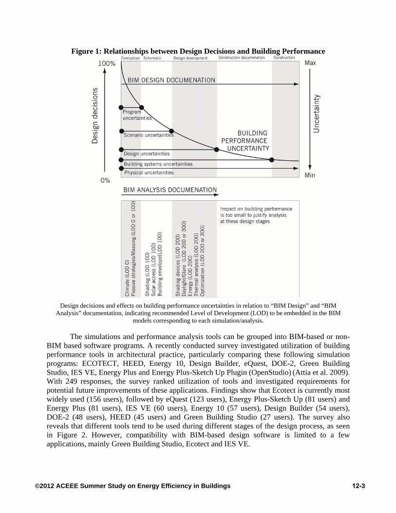
Figure 1: Relationships between Design Decisions and Building Performance
Design decisions and effects on building performance uncertainties in relation to “BIM Design” and “BIM
Analysis” documentation, indicating recommended Level of Development (LOD) to be embedded in the BIM models corresponding to each simulation/analysis.
The simulations and performance analysis tools can be grouped into BIM-based or non-BIM based software programs. A recently conducted survey investigated utilization of building performance tools in architectural practice, particularly comparing these following simulation programs: ECOTECT, HEED, Energy 10, Design Builder, eQuest, DOE-2, Green Building Studio, IES VE, Energy Plus and Energy Plus-Sketch Up Plugin (OpenStudio) (Attia et al. 2009). With 249 responses, the survey ranked utilization of tools and investigated requirements for potential future improvements of these applications. Findings show that Ecotect is currently most widely used (156 users), followed by eQuest (123 users), Energy Plus-Sketch Up (81 users) and Energy Plus (81 users), IES VE (60 users), Energy 10 (57 users), Design Builder (54 users), DOE-2 (48 users), HEED (45 users) and Green Building Studio (27 users). The survey also reveals that different tools tend to be used during different stages of the design process, as seen in Figure 2. However, compatibility with BIM-based design software is limited to a few applications, mainly Green Building Studio, Ecotect and IES VE.
12-3©2012 ACEEE Summer Study on Energy Efficiency in Buildings

Figure 2: Energy and Environmental Analysis Software in Relation to Design Stages
Information Exchange Methods between BIM and Analysis Applications
Best practices for data exchange between BIM and environmental analysis software
depend on the analysis objectives and what type of data is needed. For example, for determination of building massing that minimizes solar exposure or incident solar exposure on the facade, data exchange through DXF file format is adequate. For these types of studies, geometric properties of the building massing or component under analysis (for example, part of the facade with shading devices) are sufficient, as developed in LOD 100 model.
For other types of studies, such as daylight or thermal analysis, enriched information about interior spatial organization, material properties and properties of shading surfaces is needed. Therefore information stored in “design” BIM needs to be exported as “analysis” BIM. For example, Ecotect analysis software is designed to be used during the early stages of the design process and can be effectively used for a variety of analysis functions, such as shadow analysis, shading, solar exposure studies, lighting and daylight studies (Aksamija and Mallasi 2010). Data exchange between Revit and Ecotect can be performed using Green Building XML (gbXML), a schema specifically developed to facilitate transfer of building properties stored in BIM to analysis tools. The basic structure of gbXML consists of elements such as rooms, walls, floors, ceilings, shading surfaces and windows, which inherit properties embedded in the model (actual numeric values) and transfer to analysis applications.
The following model parameters are essential for data exchange using gbXML:
Rooms are the basis of the gbXML file. The location and properties or room elements must be specified in the model, since all the other data is associated with these elements. Only significant spaces, corresponding to thermal zones, should be defined as rooms. Smaller supportive spaces (elevator shafts, storage spaces, mechanical spaces, etc.) of minimal impact should be grouped. Rooms must be fully bounded, and setting up correct heights and dimensions is important.
Analytical surfaces (Floors, Walls, Roofs): Building elements must be bounded and connected to other elements appropriately.
12-4©2012 ACEEE Summer Study on Energy Efficiency in Buildings

Openings: Windows and skylights should be defined, but their properties can be modified in the analysis application (thicknesses, U-values, visual transmittance, solar heat gain coefficient).
Shading surfaces: Shading surfaces are treated as analytical surfaces (walls, floors or roofs) not bounding a room and are exported as simple surfaces. These basic parameters can be embedded in the model from the earliest stages of the
design process (LOD 100), and developed in LOD 200 to investigate the effects of different design scenarios. Figure 3 shows an example of a BIM Revit file (upper right) with information needed for the analysis imbedded in the model (rooms, their dimensions and properties), which get transferred by the gbXML file to the analysis engine. The gbXML file contains exactly the same information, shown here in a data view. The lower right image displays an analysis model created in Ecotect from the gbXML file. Different BIM-based energy analysis programs currently have different gbXML supporting capabilities (Moon et al. 2011). Therefore, this view would be different in other energy analysis software applications.
Figure 3: BIM “Design” and “Analysis” Models
Upper right: Revit “design” BIM and example of room properties embedded in the model; Left: gbXML data file structure properties; Lower right: Ecotect “analysis” model generated through gbXML.
12-5©2012 ACEEE Summer Study on Energy Efficiency in Buildings

BIM-Based Performance Analysis: Case Study In order to illustrate relationships between design decisions and building performance
analysis using BIM, a case study is discussed examining types of questions, modeling and data exchange, analysis processes and results. The building complex (George Mason University Science and Technology, located in Fairfax, Virginia) consists of a new building and an addition to an existing academic research center, as seen in Figure 4. There is also an existing building bounding the complex along the south-west side.
Figure 4: Performance Analysis Objectives
Objectives of this study were to analyze shading strategies, daylight levels and solar
exposure for various building orientations and components, as well as design methods for improving performance of facades. The different analyses were conducted during the schematic and design development phases. These following objectives were investigated:
Site context and shadow ranges for winter and summer solstices Addition building: shading devices on the east facade; solar exposure; daylight levels and
glare for selected laboratory spaces Addition building: shading devices on the west facade; solar exposure; daylight levels
and glare for corridor area Addition building: solar exposure and daylight for the north and south atrium facades Renovation building: shading devices on the west facade; solar exposure; daylight levels
for selected computer laboratories and glare analysis Properties of building envelope (specifically, glass selection) for improving energy
efficiency.
12-6©2012 ACEEE Summer Study on Energy Efficiency in Buildings

Information Exchange and Modeling The original BIM design documentation was used to create all analysis models, and the
data exchange was mainly performed through the gbXML format. The analysis tools that were used to study the design effects on building performance included Ecotect (for site context, shading, and solar exposure studies), Radiance (for daylight simulations and glare analysis, where the model geometry was exported from Ecotect), Green Building Studio and EnergyPlus (for energy modeling, which are not discussed in this paper). The authorizing BIM design tool was Revit, and the design team incorporated necessary design characteristics and information to streamline the data exchange between BIM design and analysis software applications using gbXML. For example, major interior spaces were declared as “Room” elements, and their volumes, dimensions, and properties were defined in the Revit model. Open spaces, such as a large atrium connecting the Addition to the existing building, were grouped according to the major thermal zones, and also declared as “Room” objects. Smaller unconditioned spaces, such as mechanical and elevator shafts, were declared as “Rooms” in order to define and transfer their basic geometry; however, they were ignored in the analysis. Building floors, walls, and shading devices were used as analytical surfaces in the model. Their characteristics (thickness and material properties) were correctly defined in Ecotect. Openings in building facades and windows were defined in Revit, however, they were modified and changed in Ecotect.
Close collaboration with the design team was necessary in order to determine the analysis objectives, and different design scenarios of interest that were investigated. The iterative design-analysis process ensured that the analysis results were used effectively to change and modify building design attributes in relation to their simulated performance. Also, proper modeling methods and LOD necessary for streamlined information exchange between design and analysis applications highly depended on the close working relationship with the design team.
Since there were several analysis objectives of interest focusing on two different buildings, different Revit design models were used to create the analysis models. Specifically, Addition and Renovation buildings were modeled in separate Revit files for design documentation, and their respective gbXML files were combined in Ecotect to perform the holistic analysis. The LOD and the needed design information depended on the specific analysis objectives, as seen in Figure 5. For example, LOD 200 was used for shading and solar exposure studies, while LOD 300 was used for detailed building facade performance studies and daylight analysis. Also, the geometry of the surrounding buildings was important for site context studies, and their basic building massing and geometry was imported through DXF file format (LOD 100). This was useful in this specific case, since only the basic building massing, form, position of the building and the overall height is important in determining the overshadowing effects. Therefore, for this specific objective the three buildings were modeled at LOD 200 (Addition, Renovation and the existing building), while the surrounding buildings on the site were modeled at LOD 100.
It is important to note that some of the analysis models needed to be modified after the design information was transferred to the analysis applications. Although gbXML file format is useful in obtaining the overall building geometry, interior partitions, surfaces and openings, their properties may not be transferred correctly. For example, for Addition building, windows along the east facade were not placed correctly and had to be manually modified in Ecotect. Also, the floor levels had to be manually changed in Ecotect, since the floor-to-floor height was not correct (the ceiling and floor surfaces were both recognized as “floors”). Modifications of geometry and
12-7©2012 ACEEE Summer Study on Energy Efficiency in Buildings

preparation of the analysis models for simulations can take significant amounts of time, but are necessary steps in the analysis process. The recommendations are to start with the basic data transferred via gbXML or DXF file format, check and review this data after it is transferred to the analysis application, and model in detail only data that is needed for a specific analysis objective. It is also recommended to keep all the analysis models as separate files.
Figure 5: Summary of LOD and Data Exchange Method between BIM Design and Analysis
The next sections review site context studies, shading and daylight analysis for east and
west facades, and discuss in more detail the analysis process and results. This is presented in order to illustrate how performance analysis can help evaluate design decisions, and assist in decision-making by providing quantifiable data.
Shading Devices and Daylight: West Façade
For the site context/shading analysis, only overall building form and general massing
information are needed, as described in the previous section. Since there is an existing building directly bounding the Addition and Renovation buildings on the south-west side (as well as other buildings in the near proximity), shadow analysis was performed for the entire site. Overall site context, surrounding buildings and daily shadow ranges for selected dates are shown in Figure 6. Gradient intensity indicates the amount of time that the selected surfaces spend in shade.
Selection of shading devices depends on the building orientation. Generally, horizontal devices should be used for south facades. Vertical devices, such as fins, should be used on the east and west facades. Since the buildings under consideration are oriented -73° from true north, relative orientation and solar position were taken into account. Detailed shading analysis was performed to understand the effects of surrounding buildings and solar access for various
12-8©2012 ACEEE Summer Study on Energy Efficiency in Buildings
building orientations, and also solar exposure analysis studies were performed for critical facades (east, west and south).
Figure 6: Site Context and Shadow Ranges for Specific Dates
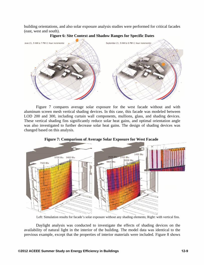
Figure 7 compares average solar exposure for the west facade without and with
aluminum screen mesh vertical shading devices. In this case, this facade was modeled between LOD 200 and 300, including curtain wall components, mullions, glass, and shading devices. These vertical shading fins significantly reduce solar heat gains, and optimal orientation angle was also investigated to further decrease solar heat gains. The design of shading devices was changed based on this analysis.
Figure 7: Comparison of Average Solar Exposure for West Facade
Left: Simulation results for facade’s solar exposure without any shading elements; Right: with vertical fins.
Daylight analysis was conducted to investigate the effects of shading devices on the availability of natural light in the interior of the building. The model data was identical to the previous example, except that the properties of interior materials were included. Figure 8 shows
12-9©2012 ACEEE Summer Study on Energy Efficiency in Buildings

daylight levels in the corridor (contour lines indicate approximately 10 fc change in values), which are sufficient for this circulation space. Therefore, it was concluded that the shading devices along the west facade effectively block solar radiation without negatively affecting the availability of natural light.
Figure 8: Daylight Levels in the Corridor (Plan View)
Shading Devices and Daylight: East Façade Initial design for the east facade of Addition building included vertical fins as shading
elements, since the rules-of-thumb indicate that they should be used on the east and west facades to block early morning and late afternoon sun. The model was created to LOD 200 to investigate solar access along this facade. It was found that the east facade annually receives only a small percentage of incident solar radiation (around 6%), and that on average spends 87% of time in shade. Average incident daily solar radiation is low due to the orientation and shading provided by the adjoining building, as seen in Figure 9. Therefore, shading devices (or other methods for controlling solar heat gain, such as fritted glass) would be redundant. Daylight levels for laboratories located on the second level are shown in Figure 10. These were simulated in order to investigate the amount of natural light that would be available in the interior spaces, and whether glare issues would be present is shades were eliminated. It was found that the daylight levels would not be too high without the shading elements, and that visual comfort conditions would be acceptable. The results of the analysis were implemented in the final design, and the shading elements were eliminated. Therefore, the performance simulations were successful in analyzing design decisions, providing quantifiable data that demonstrated that rules-of-thumb would be inaccurate for this specific building design.
12-10©2012 ACEEE Summer Study on Energy Efficiency in Buildings

Figure 9: East Facade and Shadows on June 21
Figure 10: Daylight Levels for Laboratory Spaces (3D View)
Conclusion This paper reviewed data exchange between BIM and building performance analysis
software, emphasizing differentiation between BIM “design” and “analysis” models. Interoperability between BIM-based design and simulation tools can improve the workflow between design documentation and analysis applications, where the design information contained in the models can be used for performance analysis. It is important to track what type of information is needed for a particular analysis, and how to use BIM to effectively simulate design decisions. Also, a specific case study illustrated how BIM design models can be used for building performance analysis, focusing on shading and orientation studies, solar access analysis, the performance of shading devices, and daylight simulations.
Our recommendations for successfully integrating of BIM-based building performance predictions with the design process are:
Coupling BIM-based analysis with BIM-based design production tools occurs when all
design/performance analysis team members work collaboratively within an iterative process of design decision-making.
There are both direct (gbXML) and indirect (DXF) routes for exchanging three dimensional BIM models with building performance analysis applications. It is important to know what type of design information is needed for a specific analysis, which influences selection of data transfer mechanisms between BIM design and analysis tools. For example, building form and the overall geometry transferred via DXF file format are
12-11©2012 ACEEE Summer Study on Energy Efficiency in Buildings
sufficient for site analysis, shadow and solar access analysis. For detailed energy or daylight simulations, information about interior spaces, partitions, types of materials and their properties is needed. For these types of simulations, gbXML file format should be used, since it allows this type of information to be interchanged between BIM design and analysis tools.
BIM-design and BIM-analysis models need to be managed and developed properly. In essence, BIM design models typically have too many architectural and construction details, which are not needed for the performance analysis. Therefore, understanding the level of detail needed for the simulation model is essential for successful integration.
References AIA. 2008. AIA Document E202: The American Institute of Architects Building Information
Protocol Exhibit. Aksamija, A. 2009. “Integration in Architectural Design: Methods and Implementations.” Design
Principles and Practices: An International Journal 3 (6): 151-160. Aksamija, A. 2010. “Analysis and Computation: Sustainable Design in Practice.” Design
Principles and Practices: An International Journal 4 (4): 291-314. Aksamija, A. & Z. Mallasi. 2010. “Building Performance Predictions: How Simulations Can
Improve Design Decisions.” Perkins+Will Research Journal 2 (2): 7-32. Attia S., Beltran L., de Herde A. & J. Hensen. 2009. “Architect Friendly: A Comparison of Ten
Different Building Performance Simulation Tools”, In Proceedings of IBPSA ‘09 Buildings Simulation Conference, 204-211. Glasgow: The International Building Performance Simulation Association.
Augenbroe, P., de Wilde, H., Moon, J. and A. Malkawi. 2004. “An Interoperability Workbench
for Design Analysis Integration.” Energy and Buildings, 36 (8): 737-48. Gratia, E. & de A. Herde. 2002. “A Simple Design Tool for the Thermal Study of an Office
Building.” Energy and Buildings, 34: 279-289. Moon, H., Choi1, M., Kim, S. and Ryu, S., 2011 “Case Studies for the Evaluation of
Interoperability between a BIM Based Architectural Model and Building Performance Analysis Programs” In Proceedings of IBPSA ‘11 Buildings Simulation Conference, 1521-1526. Sydney: The International Building Performance Simulation Association.
Punjabi, S. & V. Miranda. 2005. “Development of an Integrated Building Design Information
Interface”, In Proceedings of IBPSA ’05 Buildings Simulation Conference, Montreal, pp. 969-976.
Wetter, M. 2011. “A View on Future Building System Modeling and Simulation”, In Building
Performance Simulation for Design and Operation, Hensen, J. and Lamberts, R., (eds.), Routledge, UK.
12-12©2012 ACEEE Summer Study on Energy Efficiency in Buildings