Embed Size (px)
Citation preview

INDRADHANUSH GAS GRID LIMITED
(Joint Venture of IOCL, ONGC, GAIL, OIL and NRL)
GUWAHATI, ASSAM
NORTH -EAST GAS GRID PIPELINE PROJECT (PHASE-1)
BID DOCUMENT FOR PROCUREMENT
OF
BARE & COATED LINE PIPES
OPEN DOMESTIC COMPETITIVE BIDDING
Bid Document No.: 05/51/23UU/IGGL/012
VOLUME – II OF II
Visit: www.tenderwizard.com/MECON (Tenderwizard helpdesk: 011-49424365)
PREPARED AND ISSUED BY
MECON LIMITED (A Govt. of India Undertaking)
Delhi, India
Tender No.: 05/51/23UU/IGGL/012 1 of 299

CONTENTS LIST – CARBON STEEL
COATED LINE PIPES
OIL & GAS SBU, DELHI Page 1 of 2
Client : IGGL
PROJECT :
NORTH-EAST GAS GRID PIPELINE PROJECT (PHASE-1)
Document No. :
MEC/23UU/05/21/M/001/S012
Rev. No. 0
Date OCT 2019
Sl. No.
Document Title / Description Document / Drawing No.
1. MATERIAL REQUISITION FOR COATED & BARE LINE PIPES MEC/23UU/05/21/M/001/S012
2. STANDARD TECHNICAL SPECIFICATION FOR HFW LINEPIPE (ONSHORE)
MEC/TS/05/21/012
3. STANDARD TECHNICAL SPECIFICATION FOR SEAMLESS LINEPIPE (ONSHORE)
MEC/TS/05/21/012A
4. STANDARD TECHNICAL SPECIFICATION FOR SAWL LINEPIPE (ONSHORE)
MEC/TS/05/21/012B
5. STANDARD TECHNICAL SPECIFICATION FOR SAWH LINEPIPE (ONSHORE)
MEC/TS/05/21/012C
6. STANDARD TECHNICAL SPECIFICATION FOR 3-LAYER POLYETHELYNE COATING OF LINE PIPES
MEC/TS/05/21/014
7. STANDARD TECHNICAL SPECIFICATION FOR LIQUID EPOXY COATINGCOATING OF LINE PIPES
MEC/TS/05/21/014B
8. AMENDMENT TO LINE PIPE TS & COATING TS NIL
9. QUALITY ASSURANCE PLAN (GUIDELINE) QAP No.05/21/12/001
10. INSPECTION & TEST PLAN FOR ERW LINE PIPES (ONSHORE)
ITP NO.05/21/12/001
11. INSPECTION & TEST PLAN FOR SAWL LINE PIPES (ONSHORE)
ITP NO.05/21/12/002
12. INSPECTION & TEST PLAN FOR SAWH LINE PIPES (ONSHORE)
ITP NO.05/21/12/003
13. INSPECTION & TEST PLAN FOR 3-LAYER POLYETHELYNE COATING OF LINE PIPES
ITP NO.05/21/14/004
14. INSPECTION & TEST PLAN FOR INTERNAL LIQUID EPOXY COATING OF LINE PIPES
ITP NO.05/21/14/005
15. INSPECTION & TEST PLAN FOR SEAMLESS LINE PIPES (ONSHORE)
ITP NO.05/21/14/007
16. INSPECTION & TEST PLAN FOR HR COIL/PLATE ITP NO.05/21/12/006
17. TYPICAL LAYOUT PLAN FOR DUMP SITE DEVELOPMENT MEC/05/28/GEN/014/01
Tender No.: 05/51/23UU/IGGL/012 2 of 299

CONTENTS LIST – CARBON STEEL
COATED LINE PIPES
OIL & GAS SBU, DELHI Page 2 of 2
Client : IGGL
PROJECT :
NORTH-EAST GAS GRID PIPELINE PROJECT (PHASE-1)
Document No. :
MEC/23UU/05/21/M/001/S012
Rev. No. 0
Date OCT 2019
18. DETAILS OF BARBED WIRE FENCING MEC/05/28/GEN/014/02
19. REFERENCE LIST FOR SUPPLY OF STEEL PLATE / COIL DURING THE LAST 7 YEARS
MEC/23UU/05/21/M/001/S002/12
20. CHECK LIST MEC/23UU/05/21/M/001/S002/CL
Tender No.: 05/51/23UU/IGGL/012 3 of 299

INDRADHANUSH
GAS GRID LIMITED
TENDER FOR COATED & BARE LINE PIPES
FOR NORTH-EAST GAS GRID PIPELINE PROJECT
(PHASE-1) Bid No. 05/51/23UU/IGGL/012
MECON LIMITED
Page 1 of 24
MATERIAL REQUISITION
Tender No.: 05/51/23UU/IGGL/012 4 of 299

INDRADHANUSH
GAS GRID LIMITED
TENDER FOR COATED & BARE LINE PIPES
FOR NORTH-EAST GAS GRID PIPELINE PROJECT
(PHASE-1) Bid No. 05/51/23UU/IGGL/012
MECON LIMITED
Page 2 of 24
MATERIAL REQUISITION
(MR No. : MEC/23UU/05/21/M/001/S012) PROJECT: NORTH-EAST GAS GRID PIPELINE PROJECT (PHASE-1) CLIENT: INDRADHANUSH GAS GRID LIMITED TENDER NO.: 05/51/23UU/IGGL/012 Item: Supply of Coated & Bare Line Pipes, Transportation & Maintenance GROUP A:
MR Item No.
Description
Qty. (m)
Manufacturing Process
(LSAW / HSAW/HFW)
Designated “Place of
Delivery of Coated Pipe” *
Line Pipes as per API 5L, PSL-2 (46th edition) and Technical Specifications No. MEC/TS/05/21/012,MEC/TS/05/21/012B & MEC/TS/05/21/012C and 3LPE Coating as per Technical Specification No. MEC/S/05/21/014 & Internal Coating as per Technical specification No.MEC/S/05/21/014B and Amendment to TS
Specified OD
Inch (mm)
Specified W.T. (mm)
Ends Std./ Code
MaterialGrade
Finish
Min. 3LPE External Coating /Liquid Epoxy
Internal Coating
Thickness (mm/(m)
A1 24(610) 10.31 PE API 5L X-70 Coated 2.7/100 2,62,000
Bidder to indicate
DS-1 DS-2
& DS-3
A2 24(610) 12.7 PE API 5L X-70 Coated 2.7/100 1,26,000
Bidder to indicate
DS-1 DS-2
& DS-3
A3 24(610) 17.48 PE API 5L X-70 Coated 2.7/100 500
LSAW/HFW
DS-1
& DS-3
A4 24(610) 17.48 PE API 5L X-70 Bare - 100
LSAW/HFW
DS-1
& DS-3
A5 24(610) 14.27 PE API 5L X-70 Bare - 1400
LSAW/HFWDS-1
& DS-3
Tender No.: 05/51/23UU/IGGL/012 5 of 299

INDRADHANUSH
GAS GRID LIMITED
TENDER FOR COATED & BARE LINE PIPES
FOR NORTH-EAST GAS GRID PIPELINE PROJECT
(PHASE-1) Bid No. 05/51/23UU/IGGL/012
MECON LIMITED
Page 3 of 24
GROUP B:
MR Item No.
Description
Qty. (m)
Manufacturing Process
HFW/Seamless)
Designated “Place of
Delivery of Coated Pipe” *
Line Pipes as per API 5L, PSL-2 (46th edition) and Technical Specifications No. MEC/TS/05/21/012, & MEC/TS/05/21/012A and 3LPE Coating as per Technical Specification No. MEC/S/05/21/014 & Internal Coating as per Technical specification No.MEC/S/05/21/014B and Amendment to TS
Specified OD
Inch (mm)
Specified W.T. (mm)
Ends Std./ Code
MaterialGrade
Finish
Min. 3LPE External Coating
/Liquid Epoxy Internal Coating
Thickness (mm/(m)
B1 12(323.9) 7.14 PE API 5L X-70 Coated 2.2/100 1,58,00
Bidder to indicate
DS-1 DS-2
& DS-3
B2 12(323.9) 9.53 PE API 5L X-70 Coated 2.2/100 1,100
Bidder to indicate
DS-1 DS-2
& DS-3
B3 12(323.9) 9.53 PE API 5L X-70 Bare - 1,000
Bidder to indicate
DS-1 DS-2
& DS-3 * For Designated Place of delivery of coated pipe, please refer the material requisition.
Tender No.: 05/51/23UU/IGGL/012 6 of 299

INDRADHANUSH
GAS GRID LIMITED
TENDER FOR COATED & BARE LINE PIPES
FOR NORTH-EAST GAS GRID PIPELINE PROJECT
(PHASE-1) Bid No. 05/51/23UU/IGGL/012
MECON LIMITED
Page 4 of 24
Brief of scope are as follows: For Item no. A1, A2, A3, B1 & B2 Manufacture and Supply of Coated Pipe (3LPE External coating and/or Internal liquid epoxy coating, as applicable), transportation and handling of all coated pipes to designated Warehouse / Storage Yard, including arrangement and maintenance thereof. For Item No. A4, A5 & B3 Manufacture and Supply of Bare Pipe, Transportation and handling of Bare Line Pipes up to designated Storage Yard / Warehouse including arrangement & maintenance thereof. Important Note:
1. Bidders quoting for item A1 must quote for at least 100 Km quantity else bidder’s offer shall not be considered for evaluation for the corresponding item. However, the order for item will be limited to the assessed capacity and/or Evaluation Methodology as per provisions of tender document. Further, for remaining items, i.e. A2, A3, A4, A5,B1,B2 & B3 bidder has to quote for full quantity, else bidder’s offer shall not be considered for evaluation for these items.
2. Item Nos. A1, A2, A3, B1& B2 shall have External & Internal Coating.
3. Item no. A4, A5 & B3 shall be supplied in bare conditions only, without any External / Internal Coating.
4. Pipe coating implies External 3 Layer Polyethylene (3LPE) Coating and Internal Liquid Epoxy Coating (wherever applicable).
5. Detailed scope of work and technical specifications are contained elsewhere in the tender document.
6. Raw Material Inspection will also be witnessed by Owner / Owner’s representative as per Approved QAP.
Tender No.: 05/51/23UU/IGGL/012 7 of 299

INDRADHANUSH
GAS GRID LIMITED
TENDER FOR COATED & BARE LINE PIPES
FOR NORTH-EAST GAS GRID PIPELINE PROJECT
(PHASE-1) Bid No. 05/51/23UU/IGGL/012
MECON LIMITED
Page 5 of 24
7. A bidder quoting for item A3 or A4 or A5 must quote for all three Items i.e. A3, A4 and A5
together, else bidder’s offer shall not be considered for evaluation. Items A3, A4 and A5 will be clubbed together for evaluation and award.
8. A bidder quoting for item B2 or B3 must quote for all three Items i.e. B2 and B3 together,
else bidder’s offer shall not be considered for evaluation. Items B2 and B3 will be clubbed together for evaluation and award.
Tender No.: 05/51/23UU/IGGL/012 8 of 299

INDRADHANUSH
GAS GRID LIMITED
TENDER FOR COATED & BARE LINE PIPES
FOR NORTH-EAST GAS GRID PIPELINE PROJECT
(PHASE-1) Bid No. 05/51/23UU/IGGL/012
MECON LIMITED
Page 6 of 24
Proposed locations of storage yards are as under:
FOR Group A:
CODE Location of Storage
yard (PLACE/STATE)
Required Quantity in Storage Yard/ Warehouse
Item no.
Wall Thickness (mm)
Qty. (Meter)
Guwahati -Numaligarh
DS-1 (24") District Sonitpur,Assam
A1
10.31
1,00,000 DS-2 (24")
District Biswanath Assam 62,000
DS-3 (24") District Golaghat Assam 1,00,000 DS-1 (24") District Sonitpur,Assam
A2
12.70 42,000
DS-2 (24") District Biswanath Assam 42,000 DS-3 (24") District Golaghat Assam 42,000 DS-1 (24") District Sonitpur,Assam A3
17.48
250 DS-3 (24") District Golaghat Assam 250 DS-1 (24") District Sonitpur,Assam
A4 (Bare)
17.48 50
DS-3 (24") District Golaghat Assam
50
DS-1 (24") District Sonitpur,Assam A5
(Bare) 14.27
700
DS-3 (24") District Golaghat Assam
700
FOR Group B:
CODE Location of Storage yard
(PLACE/STATE)
Required Quantity in Storage Yard/ Warehouse
Item no. Wall
Thickness (mm)
Qty. (Meter)
ITANAGAR
DS-1 (12") District Biswanath,Assam B1
7.14
14,000 DS-2 (12") District Papum,
Arunachal Pradesh 14,000
DS-1 (12") District Biswanath,Assam B2
9.53
250 DS-2 (12") District Papum,
Arunachal Pradesh 250
DS-1 (12") District Biswanath,Assam B3
(Bare) 9.53
250 DS-2 (12") District Papum,
Arunachal Pradesh 250
Tender No.: 05/51/23UU/IGGL/012 9 of 299

INDRADHANUSH
GAS GRID LIMITED
TENDER FOR COATED & BARE LINE PIPES
FOR NORTH-EAST GAS GRID PIPELINE PROJECT
(PHASE-1) Bid No. 05/51/23UU/IGGL/012
MECON LIMITED
Page 7 of 24
DIMAPUR
DS-3 (12") District Golaghat,Assam B1
7.14
1,30,000
DS-3 (12") District Golaghat,Assam B2
9.53 600
DS-3 (12") District Golaghat, Assam B3 (Bare)
9.53 500
Note: Site should be within 15 km radius from the chain age locations (Details of which shall be intimated later to the successful bidder) and must be well connected to road.
i. Deviation to specifications expressed in the offer make the bid liable for rejection.
ii. Colour bands of 50 mm width to be placed at both the ends, inside of Bare Pipes at a distance
of 150 mm from the pipe ends and outside of 3LPE Coated Pipes at a distance of 450 mm from the pipe ends.
iii. White Band marking inside for all the items.
iv. Yellow Band Marking outside on each Pipes for Item A1 and Violet Marking outside on
each pipes for item A2 & White Marking outside on each pipes for item A3 as per instruction given in the MR.
v. Yellow Band Marking outside on each Pipes for Item B1 and Violet Marking outside on
each pipes for item B2 as per instruction given in the MR.
vi. Raw Material Inspection will be witnessed by Owner / Owner’s representative as per approved QAP.
vii. Inspection by vendor appointed TPI shall be as per EN 10204, 3.2certification. Inspection of
Steel Plate/Coil required for manufacturing of Line Pipe shall also be 3.2 certified as per EN 10204.
Tender No.: 05/51/23UU/IGGL/012 10 of 299

INDRADHANUSH
GAS GRID LIMITED
TENDER FOR COATED & BARE LINE PIPES
FOR NORTH-EAST GAS GRID PIPELINE PROJECT
(PHASE-1) Bid No. 05/51/23UU/IGGL/012
MECON LIMITED
Page 8 of 24
A. SCOPE OF WORK
1.0 Brief scope of works:
a) Scope of Supply of Bare/ Coated pipes as per above Mentioned Material Requisition.
b) Arrangement of land for Dump Sites adjacent to State highway/ National highway/ Railway approach and near to RoU.
c) Development of Dump Sites as detailed in the Material requirement.
d) Handling, loading and transportation of bare and coated pipes to designated Dump Sites including arrangement & provision of required number of trailers/trucks for transportation including marine/rail transportation if required.
e) Unloading, Handling & Stacking of bare and coated line pipes at Dump sites.
f) Management and Maintenance of Dump Sites.
g) Handing over of bare/ coated Line pipes to the Pipeline Laying/ installation agency progressively.
h) The Dump Sites shall be maintained for the entire duration as specified in the ‘Bid Document’.
Other requirements in respect of supply shall be as follows:-
a) Pipes shall be ordered only to Specified grade as in MR/SOR. Intermediate grades shall not be acceptable. Higher grade pipe shall not be considered as a substitute for a pipe ordered without IGGL/ MECON prior approval.
b) The manufacturer shall be required to establish and maintain quality assurance system in
accordance with ISO:9001 or equivalent. IGGL/ MECON reserve the right to audit manufacturer’s quality system.
c) GAIL is manufacturing 3LPEcompound-PB48A004 and coating contractor can opt for
external coating of pipes with IGGL’s 3LPEcompound-PB48A004 on the prevailing rate.
e) GAIL’s PE-compound can be issued from any place out of the five locations viz.
Daman, Silvassa, Dadra, Malanpur (Gwailor) and Ghaziabad. Exact location shall be decided by IGGL at the time of issuing compound material. The transportation of compound material from the place decided by IGGL shall be in the scope of coating contractor.
Tender No.: 05/51/23UU/IGGL/012 11 of 299

INDRADHANUSH
GAS GRID LIMITED
TENDER FOR COATED & BARE LINE PIPES
FOR NORTH-EAST GAS GRID PIPELINE PROJECT
(PHASE-1) Bid No. 05/51/23UU/IGGL/012
MECON LIMITED
Page 9 of 24
1.1 Works associated with External & Internal coating of Line Pipes
i) Supply of all coating materials as per specification no. MEC/S/05/21/014 for carrying out 3-layer polyethylene external coating and specification no. MEC/S/05/21/014 B, for carrying out internal coating. The bidder’s proposed coating raw material supplier(s) shall be manufacturer of the materials meant for the three layer side extruded polyethylene coating and internal epoxy coating of pipes. They must have manufactured and supplied the offered grades of materials within the last five years reckoned from the bid due date. These manufacturer(s) shall be evaluated at the bid stage and the bidder shall submit necessary letter of authorization and confirmation (as applicable) from such proposed manufacturer(s). Bidder offer shall be unconditional irrespective of the finally qualified raw material manufacturer(s).
Cleaning and surface preparation of pipes, application of 3 layer side extruded polyethylene coating & internal liquid epoxy coating on bare line pipes as applicable, carrying out inspection and testing, repairing of coating defects, re-testing, any cutting of pipes for the purpose of PQT or regular production testing, carrying out re-beveling and all associated works after cutting etc. and carrying out all coating works as per specification. Application shall also include coating of pipes of non-standard lengths obtained.
ii) The minimum thickness of finished 3LPE coating shall be
Top coat – HDPE - 2.7 mm (For 24”) & 2.2 mm (for 12”) Top coat – MDPE -3.0 mm (For 24”) & 2.4 mm (for 12”) 3LPE coating shall be used for buried pipeline sections. The 3LPE coating system consists of three layers as below:
Layer Coating
Primer FBE Mid-coat Grafted co-polymer Adhesive Top-coat High Density/Medium density polyethylene
Tender No.: 05/51/23UU/IGGL/012 12 of 299

INDRADHANUSH
GAS GRID LIMITED
TENDER FOR COATED & BARE LINE PIPES
FOR NORTH-EAST GAS GRID PIPELINE PROJECT
(PHASE-1) Bid No. 05/51/23UU/IGGL/012
MECON LIMITED
Page 10 of 24
iii) The pipes shall be furnished with liquid epoxy internal painting conforming to
ISO 15741, “Friction reduction coatings for the interior of on and offshore steel pipe lines for non-corrosive gases”/ API RP 5L 2. The coating material shall typically be two pack epoxy paint.
iv) For Internal Coating of line pipes The minimum dry film thickness shall be
100 Extremities of pipes shall be free of painting over a length of 50±5 mm.
v) A detailed procedure/ write up covering each step, starting from selection of
raw material, preparation for coating, detailed coating steps, including First Day Production test, in-house inspection, rejection and repair procedure shall be furnished.
vi) The coater shall also submit past reference of identical coating jobs with names of consultant, client, job reference and year of completion for at least one Completed job in past five years along with acceptance certificate.
vii) Bidder shall submit copy of certificate approved by Third Party Inspection Agency/Client in past showing the use of proposed raw material from a single manufacturer/brand or different manufacturers/ brand.
viii) Prior to start of production, Bidder shall, at his own cost and risk, carry out a
trial “First Day Production Coating” to prove that his plants (machinery and manpower),materials and coating procedure shall result in a quality of end product conforming to the functional requirements and properties as stated in the relevant technical specifications, standards and material manufacturer’s recommendations. At least 25 (twenty five) test pipes shall be coated in accordance with the approved procedure and relevant standards. Company representative shall select test pipes at random out of the above mentioned 25 pipes.
ix) Bidder shall submit the brief product information, application procedure and the Properties of epoxy along with write up with respect to similar earlier jobs performed (to be specified by the supplier).
Tender No.: 05/51/23UU/IGGL/012 13 of 299

INDRADHANUSH
GAS GRID LIMITED
TENDER FOR COATED & BARE LINE PIPES
FOR NORTH-EAST GAS GRID PIPELINE PROJECT
(PHASE-1) Bid No. 05/51/23UU/IGGL/012
MECON LIMITED
Page 11 of 24
x) Bidder shall submit its methods and material proposed to be used for executing the internal coating to Company and shall receive approval from Company prior to start of production. The material being proposed shall have been applied successfully in at least one project in last five years. The coating material shall be qualified as per ISO 15741/ API RP 5L 2 Latest Edition and all qualification testing should be performed by an independent laboratory. If testing is undertaken at the coating manufacturer's premises, the test shall be witnessed by the Company or by third party. The coating manufacturer shall obtain the results in the form of a full qualification report showing test method and results.
xi) Pipe surfaces shall be cleaned to SA 2½ (in accordance with ISO 8502 -3)
using suitable grit/ shot, free of any deleterious contamination or moisture. The surface roughness shall be checked at random and shall be of the range of 30-60 microns in accordance with ISO 4287-1.
xii) Loose dust and residual abrasive, which may be developed inside the pipe
during blasting process, shall be removed by high pressure air blow.
xiii) The internal pipe surface shall be visually inspected. Pipes with surface
irregularities such as laminations, shivers, scabs etc. shall be segregated and rectified.
xiv) The internal coater must guarantee and certify that the internal epoxy coating
will never affect the gas quality or the gas transport system by any transformation of the epoxy coating components during operation.
xv) The coating plant details shall be included in the bid.
xvi) The curing of the internal coating has to be such that frequent and prolonged
contact with methanol with a concentration of 100% or less does not lead to any deterioration of the characteristics of the internal coating. No softening, wrinkling or blistering of the coating may be observed.
xvii) The composition and chemical resistance of the coating shall be such that it will
never be possible to find any trace of the coating or one of its components in solid, liquid or gaseous form in the natural gas transported by the pipeline.
1.2 Works associated with Ware House/Storage yards
Bidder will be responsible for maintaining suitable warehouse facilities including preservation, traceability, security and insurance at place as defined in the State of Bihar, West Bengal and Assam for Coated / Bare pipes. The size of warehouse shall be adequate for storage of maximum quantities.
Tender No.: 05/51/23UU/IGGL/012 14 of 299

INDRADHANUSH
GAS GRID LIMITED
TENDER FOR COATED & BARE LINE PIPES
FOR NORTH-EAST GAS GRID PIPELINE PROJECT
(PHASE-1) Bid No. 05/51/23UU/IGGL/012
MECON LIMITED
Page 12 of 24
Note: Chain-age wise village to be indicated later to the successful bidder are approximate and may vary depending on availability of land, which however, has to be acquired & established by Bidder. The exact quantity to be stacked at each dump site shall be intimated to the contractor after award of work. Contractor shall be responsible for performing all works as per scope of work at the finally selected dump site locations and quantity of pipes to be stacked at no extra time / cost to the company. In case of split of order between multiple bidders, each successful bidder shall maintain his own dump site (s) near same location corresponding to ordered quantity.
Bidder(s) shall arrange for land for Ware House adjacent to State highway/National highway and near to ROU, adequate to store pipes as per the requirements stipulated and beyond the octroi limit applicability. Bidder shall enter into lease agreement with the various land owners for usage of land adequate as per the Ware House plan. The area of Ware House and number of layers for pipes shall be chosen so as to ensure safe handling of pipes and free movement of trailers. Bidder shall submit the Ware House location and layout plan for MECON/IGGL’S review/approval prior to actual acquisition of land for the said purpose.
Bidder(s) shall develop the Ware House area required for stacking/storing of specified quantity of coated / bare pipes. Bidder shall be responsible for maintaining suitable warehouse facilities including preservation, traceability, security and insurance at mentioned warehouses/Dumpsite locations. Bidder shall carry out in this regard all civil works within the Ware House required for temporary storage of pipes in all types of soils such as site grading, clearing, cutting, leveling, filling-up, providing temporary internal roads duly compacted for movement of cranes/trailers within the Ware House, providing temporary fencing and gates/barrier, cabins etc. as per the relevant drawings and other requirements indicated in the Contract document. Bidder shall be responsible for temporary land acquisition for Ware House, making approach road as required to the Ware House from the nearest main road including compensation to land owner(s) for the approach road, permission for the approach road, etc.
In case any tree cutting is involved, the disposal of uprooted trees shall be as per prevailing environment protection law. All internal access roads shall be dressed and consolidated by means of power driven rollers to obtain maximum compaction. Bidder shall also provide adequate drainage within the Ware House. All leveling, dressing and consolidation works shall be carried out as per the instructions of Company Representative. Bidder shall obtain tree cutting permission from concerned authority wherever applicable.
Tender No.: 05/51/23UU/IGGL/012 15 of 299

INDRADHANUSH
GAS GRID LIMITED
TENDER FOR COATED & BARE LINE PIPES
FOR NORTH-EAST GAS GRID PIPELINE PROJECT
(PHASE-1) Bid No. 05/51/23UU/IGGL/012
MECON LIMITED
Page 13 of 24
i) A typical layout of storage yards sketch no. MEC/05/28/GEN/014/01 is enclosed for reference purpose. Bidder shall develop a detailed development plan of Ware House including approach road and obtain MECON/IGGL’S approval prior to acquisition of land and commencement of Ware House development works. The area of Ware House shall be chosen so as to ensure safe handling of pipes and free movement of
ii) The Ware House shall be provided with barbed wire fencing (Drawing
no.MEC/05/28/GEN/014/02)
iii) The bare/coated pipes within the Ware House may be stacked by placing them on ridges of sand free from stones and covered with a plastic film or on wooden supports provided with suitable cover. Supply of sand and other materials shall be in Bidder’s scope. This cover may consist of dry, germ free straw with a plastic film, otherwise foam rubber shall be used. The support shall be spaced in such a manner as to avoid permanent bending of the pipes. Bare pipe stacks shall consist of limited number of layers so that overstressing & deformation of the pipe is avoided. In case of coated pipes, stacks shall consist of limited number of layers so that the pressure exercised by the pipe’s own weight does not cause deformation of the line pipe/ damages to coating. Each section shall be separated by means of spacers suitably spaced for this purpose. Calculation for stacking arrangement for bare/coated pipes and number of layers of pipes at storage yards shall be submitted by the coating contractor and approved by MECON/IGGL.
iv) Bidder shall also be responsible for providing illumination at the Ware House.
The illumination shall be 10 to 15 lux minimum and shall be provided with 11 meters flood light poles. The required power for the lighting shall be arranged by the Bidder.
v) Bidder shall be responsible for maintenance and management of Storage yards/
Ware House for the time specified elsewhere in the tender document or as advised by MECON/IGGL including providing security guard etc.
vi) The Storage yards/ Ware House shall be restored to original status before
handing over to the land owner. Bidder shall carry out all activities related to restoration. The rates quoted shall include all such aspects.
Tender No.: 05/51/23UU/IGGL/012 16 of 299

INDRADHANUSH
GAS GRID LIMITED
TENDER FOR COATED & BARE LINE PIPES
FOR NORTH-EAST GAS GRID PIPELINE PROJECT
(PHASE-1) Bid No. 05/51/23UU/IGGL/012
MECON LIMITED
Page 14 of 24
vii) Bidder shall furnish No Dues/ No Objection certificate from land owner upon handing over the land to its owner after completion of works.
viii) Handing over of pipes to laying contractor progressively, based on the
construction requirement. Inspection of all bare & coated line pipes in presence of company representative while handing over of pipes to laying contractor at Storage yards/ Ware House. Repair of damaged pipes, beveled end defects and damaged coating (including supply of coating materials for repair) noticed at the time of handing over of bare/ coated pipes to laying contractor. All handling, lifting tools etc. required for inspection of coated/ bare line pipes at Ware House shall be carried out by the bidder. Bidder shall load the coated & bare pipes on to the truck/ trailer (arranged by Installation Agency) at the Storage yards/ Ware House during handing over.
ix) Handing over of all surplus coated & bare pipes to laying contractor at the
Storage yards/ Ware House at the end of work. 1.3 Materials to be supplied by Bidder
Bidder shall procure and supply in sequence and at appropriate time, all corrosion
coating materials, repair materials, all accessories, consumables and utilities required for completion of works. The rates quoted for the execution of the work shall be inclusive of supply of these materials. All materials supplied shall be strictly in accordance with the requirements of relevant applicable Company specifications enclosed.
Materials to be supplied shall include, but not limited to, the following:
a) All materials and equipment required for repair, re-beveling and / or
cutting out defects of bare pipes. b) All consumables, equipment required for surface cleaning / preparation etc. c) Coating materials and other materials, equipment, consumables as required for coating. d) All materials and equipment required for conducting all types of inspection
and tests including non-destructive testing of pipes after rebevelling/ grinding. e) All materials and equipment required for repairing of defects of coated
pipes and thereafter re-testing. f) All equipment, tools, tackles, trucks/ trailers, devices required for loading,
transportation, hauling, handling, unloading, stacking, and storage of bare/ coated pipes.
Tender No.: 05/51/23UU/IGGL/012 17 of 299

INDRADHANUSH
GAS GRID LIMITED
TENDER FOR COATED & BARE LINE PIPES
FOR NORTH-EAST GAS GRID PIPELINE PROJECT
(PHASE-1) Bid No. 05/51/23UU/IGGL/012
MECON LIMITED
Page 15 of 24
g) Any other items not mentioned above but required for timely completion of
work in all respect. 1.4 Other Requirements
i) The coating plant, equipment, machinery and other facilities shall be in good operating condition to meet the job requirement of quality and production. Worn out or improvised plant are not acceptable. The coating plant(s) for the work shall be of size and capacity that shall be suitable for the scale of work, production rate, time schedule specified elsewhere in the tender document.
ii) Bidder shall, at his own responsibility and cost, provide and prepare all
necessary area for the storage of pipes and all other materials for coating yard, stock piling, and other temporary installation. Bidder shall provide servitude agreements as required with the relevant authorities and on work completion to clean, restore and pay settlements and claim for damages.
iii) It is mandatory for the Bidder to provide all testing instruments/ equipment
required for qualification, pre production and regular production testing with adequate inventory to carry out tests required within the coating yard. No outside testing is acceptable for this purpose.
iv) Bidder shall, at his own responsibility and cost, provide water and power supply
and other utilities, obtain permit regarding access roads and other permits required for the execution of works conforming to all the requirements of the governing authorities.
v) All handling, loading, unloading, stacking/storing shall be done in such a
manner as to minimise mechanical damages & corrosion and as per the procedure approved by the Company. a. All handling shall be done with slings or padded hooks.
b. Trailers shall be cleaned of debris or any other substance that might damage
the pipe. c. Suitable timber and other dunnage shall be used to protect the pipes against
the damage during transit. d. Loading shall be done in accordance with API RP 5L1 and procedure
approved by the Company. e. Finished pipe to be stored for a significant period of time in the coating
yard in a manner to prevent corrosion and damages to the coating.
vi) A NACE Level-II coating specialist shall be made available during entire duration of coating works.
Tender No.: 05/51/23UU/IGGL/012 18 of 299
INDRADHANUSH
GAS GRID LIMITED
TENDER FOR COATED & BARE LINE PIPES
FOR NORTH-EAST GAS GRID PIPELINE PROJECT
(PHASE-1) Bid No. 05/51/23UU/IGGL/012
MECON LIMITED
Page 16 of 24
vii) Coating wastage generated due to standard cut backs on external coating shall be the property of the Bidder.
viii) Any other works not listed specifically herein but required to be carried out by
the Bidder in order to complete the job in all respects, shall also form a part of Bidder’s scope.
Tender No.: 05/51/23UU/IGGL/012 19 of 299

INDRADHANUSH
GAS GRID LIMITED
TENDER FOR COATED & BARE LINE PIPES
FOR NORTH-EAST GAS GRID PIPELINE PROJECT
(PHASE-1) Bid No. 05/51/23UU/IGGL/012
MECON LIMITED
Page 17 of 24
B. REMARKS / COMMENTS 1. GENERAL NOTED
VENDOR’S COMPLIANCE Vendor must include the following statement in his bid: We certify that our bid is fully complying with your enquiry dated ………………. And referenced …………………………. Compliance with this material requisition in any instance shall not relieve the Vendor of his responsibility to meet the specified performance.
2. COMPLIANCE WITH SPECIFICATION
The vendor shall be completely responsible for the receiving/ taking over, design, materials, fabrication, testing, inspection, preparation for shipment, transport, storage at specified Dump Yard/ Warehouse and delivery to designated pipeline laying contractor of the above items strictly in accordance with the Material Requisition and all attachments thereto.
3. INSPECTION
Vendor shall appoint anyone of the following TPIA for inspection purpose. Vendor has to propose minimum 4 nos. of below listed agencies to be approved by IGGL/ MECON.
1) Det Norske Veritas (DNV) 2) Germanischer Lloyd 3) Bureau Veritas 4) Moody International 5) SGS 6) Certification Engineer International Ltd(CEIL) 7) Technische Ulierwachungs Verein (TUV) 8) Velosi 9) American Bureau Services(ABS) 10) AB-Vincotee 11) LIoyd Register of Industrial Services 12) VCS Quality Services Private Limited 13) Meenar Global
Apart from inspection by TPIA, inspection shall also be performed by IGGL and or its authorized representative / MECON and or its authorized inspection agency (AIA), as set out and specified in the codes and particular documents forming this MR.
Tender No.: 05/51/23UU/IGGL/012 20 of 299

INDRADHANUSH
GAS GRID LIMITED
TENDER FOR COATED & BARE LINE PIPES
FOR NORTH-EAST GAS GRID PIPELINE PROJECT
(PHASE-1) Bid No. 05/51/23UU/IGGL/012
MECON LIMITED
Page 18 of 24
4. CERTIFICATION
The vendor shall be completely responsible for the design, materials, fabrication, coating, testing, inspection, preparation for shipment, loading of the above item strictly in accordance with the Material Requisition and all attachments thereto. All items shall be provided with EN 10204, 3.2 Certification. The steel plate/coil required for pipe manufacturing shall also be certified as per EN 10204, 3.2 Certification.
5. Procurement of Steel Plates/ Coils/Billets
5.1 List of acceptable Steel Plate/Coil/Billet Manufacturer
The following steel manufacturers are acceptable for the supply of Steel Plates/Coil/Billets to be used in the manufacture of quoted line pipes. The Pipe manufacturer shall furnish specific confirmation for compliance to specifications from any of two (2) proposed steel plate/coil/Billets manufacturer(s). For Plate (Upto X-70 )
1. Mannesmann Salzgitter Roehrenwerke, Germany
2. Dillinger, Germany
3. JSW Steel, USA
4. Ilva, Itay
5. Azovstahl, Ukraine
6. Arcelor Mittal,France/Germany
7. Voest Alpine, Austria
8. Sumitomo Metal, Japan
9. Nippon Steel, Japan
10. Usimians, Brazil
11. Posco, South Korea
12. Welspun PCMD, India
13. Baoshan Iron & Steel Co. Ltd, Shangai, China
14. Essar Steel, India
15. Jindal Steel & Power Ltd ( up to 20.6 mm)
16. Rourkela Steel Plant (SAIL) (up to 23.8 mm)
Tender No.: 05/51/23UU/IGGL/012 21 of 299

INDRADHANUSH
GAS GRID LIMITED
TENDER FOR COATED & BARE LINE PIPES
FOR NORTH-EAST GAS GRID PIPELINE PROJECT
(PHASE-1) Bid No. 05/51/23UU/IGGL/012
MECON LIMITED
Page 19 of 24
For Coil (Upto X-70 )
1. Thyssen Krupp, Germany
2. AHMSA (Altos Hornos De Mexico), Mexico
3. Baoshan Iron & Steel Co. Ltd, Shangai, China
4. Wuhan Iron & Steel, China
5. US Steel Kosice, Slovak Republic
6. Essar Steel, India
7. Erdemir, Turkey
8. Posco, South Korea
9. TISCO (Group) Co.Ltd, China
10. Maanshan Iron & Steel Co. Ltd., China
11. Jinan Iron & Steel Co.Ltd., China
12. Benxi Iron & Steel, China
13. Jiangsu Shagang (Group), China
14. Shou-gang Qian Iron & Steel Co. Ltd., China
15. Hyundai Steel, South Korea
16. Hadeed Saudi Iron & Steel Co., Saudi Arabia
17. Hunan Valin Lianyuan Steel Co.Ltd. China (Arecelor Mittal Group)
18. Arcelor Mittal,France/Germany
19. Anyang Iron & Steel Group Co.Ltd. China
20. Angang Steel Co.Ltd., China
21. HBIS Hebei Iron & Steel Group Co.Ltd, China
22. Megasteel, Malaysia (upto X-70, WT-10.3mm)
23. JSW steel limited, Dolvi, India (earlier Ispat (up to X-70, WT-11.7mm)
24. SAIL, Bokaro,India (upto X-70, WT-11.1mm)
25. JSW Steel Limited, Vijayanagar, Bellary, India
27. Tata Steel Limited, Jamshedpur (up to API 5L X-60 & WT up to 9.35 mm)
28 Tata Steel Limited, Kalinganagar (up to API 5L X-60 & WT up to 13.0 mm)
29 Tata Steel BSL Limited, Meramandali (up to API 5L X-70 & WT up to 12.7
mm)
Tender No.: 05/51/23UU/IGGL/012 22 of 299

INDRADHANUSH
GAS GRID LIMITED
TENDER FOR COATED & BARE LINE PIPES
FOR NORTH-EAST GAS GRID PIPELINE PROJECT
(PHASE-1) Bid No. 05/51/23UU/IGGL/012
MECON LIMITED
Page 20 of 24
FOR Billets 1. Jindal Steel Limited, Vijay Nagar
2. Jindal Steel & power Limited,Raigarg,Chhatisgarh
3. JSW Steel Limited, Salem
4. Kalyani Steel Limited, Hospet
5.2 In case bidder proposes steel plate/coil manufacturer(s) not covered in the above list, then the proposed steel plates/ coils/Billets manufacturer must meet the following criteria :-
5.3 Steel plate/coil manufacturer(s) must have manufactured and supplied in a single order, at least 5000 MT steel plate/coil/Billets for the production of line pipes conforming to API 5L (PSL-2) of the same or higher grade as quoted for in the last seven(07) years from the bid due date.
5.4 The steel plate/coil manufacturer have manufactured plate/coils/Billets conforming to API 5L (PSL-2) of same or higher wall thickness as quoted for in the last seven(07) years from the bid due date.
5.5 The steel plate/coil manufacturer must have manufactured plate/coils conforming to API 5L (PSL-2) which are equal or higher in terms of plate width as quoted for in case of LSAW option.
5.6 A letter of commitment from proposed steel plate/coil/Billets manufacturer for supply of steel plates/coils/Billets required from two (2) manufacturers for the manufacture of line pipes under present bid.
5.7 Confirmation regarding compliance with applicable requirements for steel plates/coils/Billets specified in Technical Specifications/ Material Requisition of this Bid Document from the proposed steel manufacture shall be furnished.
Pipe Manufacturer must submit the track record, along with bid, in duly filled up “Annexure A” with documentary evidence (of steel plate/Coil manufacturer) to establish the above qualification criteria indicated above at clause No.5.3,5.4,5.5,5.6 & 5.7 Such as Purchase order/work order, inspection release4 note/completion certificate of relevant previous supplies
In the absence of such documentary evidence, Owner/ Consultant reserve the right to reject the bid without making any reference to the bidder.
Tender No.: 05/51/23UU/IGGL/012 23 of 299

INDRADHANUSH
GAS GRID LIMITED
TENDER FOR COATED & BARE LINE PIPES
FOR NORTH-EAST GAS GRID PIPELINE PROJECT
(PHASE-1) Bid No. 05/51/23UU/IGGL/012
MECON LIMITED
Page 21 of 24
5.8 Bidder to note that steel plate/coil manufacturer shall be qualified at bid stage only.
5.9 The techno commercially qualified bidder(s) will be informed prior to price bid opening on acceptance of the proposed steel plate / coil/Billets manufacturer(s), if any.
5.10 Bidder’s offer shall be unconditional irrespective of the finally qualified steel plate /coils/Billets manufacturer(s).
5.11 Steel Mill qualified for one bidder during bidding stage shall be considered qualified
for other bidder also. The list of all acceptable steel manufacturers shall be communicated to all qualified bidders.
6. VENDOR’S DOCUMENTS
The drawings/documents shall be reviewed, checked, approved and duly signed/stamped by successful manufacturer/supplier before submission. Revision number shall be changed during submission of the revised documents and all revisions shall be highlighted by clouds. Whenever the successful Bidder/supplier require any sub-supplier drawings to be reviewed by MECON, the same shall be submitted by the supplier after duly reviewed, approved and stamped by the successful Bidder/supplier. Direct submission of the sub-supplier’s drawings without Manufacturer/supplier’s approval shall not be entertained.
Review/Approval of the successful Manufacturer/supplier drawings/documents by MECON would be only to review the compatibility with basic designs and concepts and in no way absolve the successful Manufacturer/supplier of his responsibility/contractual obligation to comply with PR requirements, applicable codes, specifications and statutory rules/regulations. Any error/deficiency noticed during any stage of manufacturing/execution/installation shall be promptly corrected by the successful Manufacturer/supplier without any extra cost or time, whether or not comments on the same were received from MECON during the drawing review stage.
The successful Manufacturer/supplier shall submit a prerecorded Training CDs/DVDs and it shall comprise the basic theories and fundamentals, related standards, design parameters, manufacturing & inspection methods, and other relevant details. The CDs/DVDs shall have to be self-contained, user-friendly using animation/videos and other multimedia techniques.
Vendor shall supply the documentation as listed under point C of this Material Requisition.
Tender No.: 05/51/23UU/IGGL/012 24 of 299

INDRADHANUSH
GAS GRID LIMITED
TENDER FOR COATED & BARE LINE PIPES
FOR NORTH-EAST GAS GRID PIPELINE PROJECT
(PHASE-1) Bid No. 05/51/23UU/IGGL/012
MECON LIMITED
Page 22 of 24
All documents shall be supplied in English language.
Vendor shall strictly follow the document numbering procedure in their document as illustrated below:
Where,
Project No. is 23UU
Item is LPBR/COAT depending on bare or coated
Document Index No. will be of three characters as indicated under point D of this MR;
Serial No. shall be 4 digit no. ranging from 0001 to 9999
Revision No. is Revision of the document starting with Ro, R1 ……;
Example: For QA/QC program, the document no. will be
0000 LPBR/LPCOAT QAP 0001 R0
Project No.
Item Document Index No. Serial No. Revision No.
Tender No.: 05/51/23UU/IGGL/012 25 of 299
INDRADHANUSH
GAS GRID LIMITED
TENDER FOR COATED & BARE LINE PIPES
FOR NORTH-EAST GAS GRID PIPELINE PROJECT
(PHASE-1) Bid No. 05/51/23UU/IGGL/012
MECON LIMITED
Page 23 of 24
C. DOCUMENTS & DATA REQUIREMENTS
The table hereunder specifies the quantities and the nature of the documents to be submitted by the CONTRACTOR to IGGL/MECON. The documents required at the inquiry stage and to be included in the bid are listed under column A. The documents required after award of the AGREEMENT and subject to the written approval of the IGGL/MECON are listed under column B. The final and certified documents are listed under column C. Any document, even when preliminary, shall be binding and therefore duly identified and signed by the CONTRACTOR. It shall bear the Project reference, the material Requisition number and the identification number. THE DOCUMENTS ARE FULLY PART OF THE SUPPLY WHICH SHALL BE COMPLETE ONLY IF AND WHEN THE DOCUMENTS COMPLYING FULLY WITH THE MATERIAL REQUISITION REQUIREMENTS ARE RECEIVED BY THE ENGINEER.
Item Documents and Data Document Index No.
A B C No. of copies
No. of copies
Required date
No. of copies
Required date
1 Drawing/data submittal list/schedule
DLS 1 3 2 weeks +weekly
3 2 weeks after
approval 2 Fabrication//Rolling,
test and delivery schedule (per item)
FTD 1 3 2 weeks +weekly
3 1 within weeks
3 Progress report PRT 3 Daily +weekly
Daily +weekly
4 Catalogues / References
CRS 1
5 Code compliance certificate
CCC 3 2 weeks 3 1 week after
approval 6 The welding method
and welding procedure specification and records WPS/PQR for EW or Manufacturing Process for Seamless
WPS/MPS 1 3 Within 2 weeks
1 week after
approval + with final techn. file
7 QA/QC program QAP 1 3 2 weeks 3 8 Inspection and test ITP 1 3 2 weeks 3
Tender No.: 05/51/23UU/IGGL/012 26 of 299

INDRADHANUSH
GAS GRID LIMITED
TENDER FOR COATED & BARE LINE PIPES
FOR NORTH-EAST GAS GRID PIPELINE PROJECT
(PHASE-1) Bid No. 05/51/23UU/IGGL/012
MECON LIMITED
Page 24 of 24
Item Documents and Data Document Index No.
A B C No. of copies
No. of copies
Required date
No. of copies
Required date
procedure 9 NDE reports NDR 3 When
available 3 1 week
after approval + with final techn. file
10 Hydro-test report HTR 3 When available
3 2 weeks after
approval + with final techn. file
11 List of subcontractors with their scope
LSS 3 2 weeks With final techn. file
12 Copy of purchase orders to subcontractors
CPS 3 2 weeks With final techn. file
13 Copy of purchase order CPO With final techn. file
14 Packing/shipping list w/weights and dimensions
PSD 3 2 weeks 3 2 weeks before
shipping 15 Final technical file FTF 6 With
shipping NOTES 1) Durations in column B (Required date) are weeks after LOA or as indicated in Table
Durations in column C (Required date) are weeks after document approval or as indicated in Table.
Due date of each document may be proposed.
2) Latest submittal time for: Test procedure : 2 weeks before test Test report : 2 week after test
3) Final technical file shall be supplied in hard copy as indicated, and in electronic format (.pdf
Acrobat files) on six (6) CD-ROMs.
Tender No.: 05/51/23UU/IGGL/012 27 of 299

Tender No.: 05/51/23UU/IGGL/012 28 of 299

Tender No.: 05/51/23UU/IGGL/012 29 of 299

Tender No.: 05/51/23UU/IGGL/012 30 of 299

Tender No.: 05/51/23UU/IGGL/012 31 of 299

Tender No.: 05/51/23UU/IGGL/012 32 of 299

Tender No.: 05/51/23UU/IGGL/012 33 of 299

Tender No.: 05/51/23UU/IGGL/012 34 of 299

Tender No.: 05/51/23UU/IGGL/012 35 of 299

Tender No.: 05/51/23UU/IGGL/012 36 of 299

Tender No.: 05/51/23UU/IGGL/012 37 of 299

Tender No.: 05/51/23UU/IGGL/012 38 of 299

Tender No.: 05/51/23UU/IGGL/012 39 of 299
Tender No.: 05/51/23UU/IGGL/012 40 of 299

Tender No.: 05/51/23UU/IGGL/012 41 of 299

Tender No.: 05/51/23UU/IGGL/012 42 of 299

Tender No.: 05/51/23UU/IGGL/012 43 of 299

Tender No.: 05/51/23UU/IGGL/012 44 of 299

Tender No.: 05/51/23UU/IGGL/012 45 of 299

Tender No.: 05/51/23UU/IGGL/012 46 of 299

Tender No.: 05/51/23UU/IGGL/012 47 of 299

Tender No.: 05/51/23UU/IGGL/012 48 of 299

Tender No.: 05/51/23UU/IGGL/012 49 of 299

Tender No.: 05/51/23UU/IGGL/012 50 of 299

Tender No.: 05/51/23UU/IGGL/012 51 of 299

Tender No.: 05/51/23UU/IGGL/012 52 of 299
Tender No.: 05/51/23UU/IGGL/012 53 of 299

Tender No.: 05/51/23UU/IGGL/012 54 of 299

Tender No.: 05/51/23UU/IGGL/012 55 of 299

Tender No.: 05/51/23UU/IGGL/012 56 of 299

Tender No.: 05/51/23UU/IGGL/012 57 of 299

Tender No.: 05/51/23UU/IGGL/012 58 of 299

Tender No.: 05/51/23UU/IGGL/012 59 of 299

Tender No.: 05/51/23UU/IGGL/012 60 of 299

Tender No.: 05/51/23UU/IGGL/012 61 of 299

Tender No.: 05/51/23UU/IGGL/012 62 of 299

Tender No.: 05/51/23UU/IGGL/012 63 of 299

Tender No.: 05/51/23UU/IGGL/012 64 of 299
Tender No.: 05/51/23UU/IGGL/012 65 of 299

STANDARD SPECIFICATION FOR
SEAMLESS LINE PIPE (ONSHORE)
SPECIFICATION NO.: EC S 05/21/012A
(OIL & GAS SBU) MECON LIMITED
DELHI 110 092
PREPARED BY: CHECKED BY: APPROVED BY: ISSUE DATE:
,.,
SACHIN KUMAR (S.D.E.)
IN SINGHAL (MANAGER)
K. P. SINGH (D.G.M)
20.11.2018
Tender No.: 05/51/23UU/IGGL/012 66 of 299

MECON LIMITED REGD. OFF: RANCH' 834002
STANDARD TECHNICAL SPECIFICATION .
OIL & GAS SBU, DELHI ...00
TITLE STANDARD SPECIFICATION
FOR SEAMLESS LINE PIPE (ONSHORE)
_,..
DOCUMENT NO. •
MEC/TS/05/21/012A
Page 2 of 29
EDITION : 2
REVISION : 0
Abbreviations:
API ASTM CE CVN SMLS ID Kv L
American Petroleum Institute American Society for Testing and Materials Carbon Equivalent Charpy V441otch Seamless Inside Diameter Chem value in pipe longitudinal direction
KvT Charpy value in pipe transverse direction MPQT Manufacturing Procedure Qualification Tests MPS Manufacturing Procedure Specification PSL Product Specification Level MPT Magnetic Particle Testing NOT Non Destructive Testing OD/D Outside Diameter, Specified t Wall Thickness, Specified UT Ultrasonic Testing
Tender No.: 05/51/23UU/IGGL/012 67 of 299

MECON
REGD. OFF: RANCHI 834002
LIMITED STANDARD TECHNICAL SPECIFICATION
OIL & GAS SBU, DELHI
TITLE STANDARD SPECIFICATION
FOR SEAMLESS LINE PIPE (ONSHORE)
DOCUMENT NO.
MEC/TS/05/21/012A
Page 3 of 29
EDITION : 2
REVISION : 0
CONTENTS
1 SCOPE 4
3 NORMATIVE REFERENCES 4
6 PIPE GRADE, STEEL GRADE AND DELIVERY CONDITION. 4
8 MANUFACTURING 5
9 ACCEPTANCE CRITERIA 6
10 INSPECTION 12
11 MARKING 17
12 COATINGS AND THREAD PROTECTORS 18
13 RETENTION OF RECORDS • 18
14 PRODUCTION REPORT 18
15 ONLINE PIPE TRACKING DATA ............ ...... ............. 19
16 PIPE LOADING 19
17 INSPECTION OF FIELD TESTS & WARRANTY 20
Annex B 21
Annex C 24
Annex E 25
Annex Q (New) 29
FIGURE: 10 2 4 8 30
Tender No.: 05/51/23UU/IGGL/012 68 of 299

MECON LIMITED REGD. OFF: RANCHI 834002
STANDARD TECHNICAL SPECIFICATION
OIL & GAS SBU, DELHI .....0
TITLE STANDARD SPECIFICATION
FOR SEAMLESS UNE PIPE (ONSHORE)
DOCUMENT NO.
MEC/TS/05/21/012A
Page 4 of 29
EDITION : 2
REVISION : 0
1
1.1 (New)
1.2 (New)
SCOPE
This specification establishes the minimum requirements for the manufacture of seamless carbon steel line pipe in accordance with the requirements of API (American Petroleum Institute) Specification 5L, Forty-Fifth Edition, 2012 and makes restrictive amendments to API Specification 5L. Unless modified and/or deleted by this specification, the requirements of API Specification 5L. shall remain applicable.
The sections, paragraphs and annexes contained herein have the same numbering as that of API Spec M. in order to facilitate reference. Additional requirements, which are not specified in API Spec 5L, have also been numbered and marked as "(New)".
The coverage by this specification is limited to line pipe to be used in onshore pipelines transporting non-sour hydrocarbons in liquid or gaseous phase. The product specification level for line pipe to be supplied as per this specification shall be "PSL 2".
The Manufacturer shall have a valid license to use API Monogram in accordance with the requirements of Specification 5L, Forty-Fifth Edition, 2012 for line pipe as Product Specification Level PSL 2.
Pipe Size
This Specification shall be applied to line pipe of size 4 1/2" OD thru 20" OD (both sizes included).
Grades
This specification is applicable to line pipes of Grade B through X-70.
NORMATIVE REFERENCES
The latest edition (edition enforce at the time of issue of enquiry) of following additional references are included in this specification:
ASTIR ,
ASTM El 12-12: Standard Test Methods for Determining Average Grain Size ASTM A370
: Standard Test Methods and Definitions for Mechanical Testing of Steel Products
6 PIPE GRADE, STEEL GRADE AND DELIVERY CONDITION
6.1 Pipe grade and steel grade
6.1.2 Line pipe supplied to this specification shall conform to Product Specification Level 2
Tender No.: 05/51/23UU/IGGL/012 69 of 299

MECON LIMITED REGD. OFF: RANCHI 834002
STANDARD TECHNICAL SPECIFICATION Aet-'
OIL & GAS SBU, DELHI
TITLE STANDARD SPECIFICATION
FOR SEAMLESS LINE PIPE (ONSHORE)
DOCUMENT NO.
MEC/TS/05/21/012A
Page 5 of 29
EDITION : 2
REVISION : 0
(PSL 2) as given in Table 1 of this specification and consists of an alpha or alphanumeric designation that identifies the strength level of the pipe. The steel name (designating a steel grade), linked to the chemical composition of the steel, additionally includes a suffix that consists of a single letter (M) that identifies the delivery condition as per Table 3 of this specification.
Table 1 of API Spec 51.. stands replaced by Table I of this specification.
Table I - Rim grades, steel grades and acceptable delivery conditions
PSL Delivery Condition Pipe grade/ steel grades b
PSL 2 Normalizing or quenched and tempered
BM, X42M, X46M, X52M, X56M, X60M, X65M, X7OM
a Deleted
b The suffix (M) for PSL 2 grades belongs to steel grade
6.2 Delivery condition
6.2.2 The delivery condition for starting material shall be in accordance with Table I of this specification.
8 MANUFACTURING
8.1 Process of Manufacture
Pipe furnished to this specification shall be manufactured in accordance with the applicable requirements and limitations given in Table 2 of API Spec 5E. and Table 3 of this specification.
Table 3 of API Spec 5E. stands replaced by Table 3 of this specification.
Table 3 - Acceptable manufacturing routes for MIL 2 pipe
Type of On
Starting material Pipe forming Pipe heat treatment
Delivery condition
SMLS Ingot, bloom or billet Hot form and ing cold fini
Normalized or quenching and
tempering N or Q
8.3 Starting Material
8.3.2 Line pipe furnished to this specification shall be made from steel produced in basic oxygen or electric arc furnace. Steel shall be made by continuous casting only.
Tender No.: 05/51/23UU/IGGL/012 70 of 299

MECON LIMITED REGD. OFF: RANCH! 834002
STANDARD 'TECHNICAL SPECIFICATION
OIL & GAS SKI, DELHI
TITLE STANDARD SPECIFICATION
FOR SEAMLESS LINE PIPE (ONSHORE)
DOCUMENT NO.
MEC/TS/05/21/012A
Page 6 of 29
EDITION : 2
REVISION : 0
8.3.3 • The steel used for manufacture Of pipe shall be fully killed and fine grained with ASTM grain size number 7 or finer as per ASTM E 112 .
8.9 Cold sizing and cold expansion
8.9.1 Pipes furnished to this specification shall be non-expanded.
8.11 Jointers
8.11.1 Jointers on pipes are not permitted.
9 ACCEPTANCE CRITERIA
9.2
Chemical composition 9.2.2
For pipes supplied as per this specification, the chemical composition of each heat of steel on product analysis shall be as given in Table 5 of this specification.
Table 5 of API Spec 5L stands replaced by Table 5 of this specification.
Table 5 - Chemical composition for pipe
Element Mass fr on, bssed u heat and product analyses (%)
For Grades B to X70
C b 0.16 max. (For Grade B to X56)
0.12 f max.(For Grade X60 to X70)
Si 0.15 m(New) min.
0.45 MU.
Mnb
1.20 Max. (For Grade B)
1.30 max. (For Grade 42 & X46)
1.40 Tax. For Grade X52 & X56) 1.60 m,uc. (For Grade X6Q to X70)
P 0.020 MIX.
7 0.010 max.
Vd 0.05 max. (For Grade B to X56) 0.08 max. (For Grade X60 to X70)
bbd
0.05 max. (For Grade B to X46)
0.10 max. (For Grade X52 to X70) Tid 0.04 max.
Al n (Nev) 0.02 °04") min.
0.07 max.
Tender No.: 05/51/23UU/IGGL/012 71 of 299

MECON
REGD. OFF: RANCH! 834002
STANDARD TECHNICAL SPECIFICATION UNITED
OIL & GAS SBU, DELHI 044 ....0
TITLE STANDARD SPECIFICATION
FOR SEAMLESS LINE PIPE (ONSHORE)
DOCUMENT NO.
MEC/TS/05/21/012A
Page 7 of , 29
EDITION : 2
REVISION : 0
Element Mass fraction, based upon heat and product analyses (%)
Cr 0.20 max. Mo 0.28 max.
Cu ' N e w ) • 0.35 • max. Ni p ( N e w ) 0.20 max.
0.012 max.
B ' 0.0005 max.
Ca 0.006 nax.
Notes to Table 5: •
Based upon product analysis as per clause 9.2.4 and 9.2.5 of API Spec 5L, the CEp cm limits a
apply if C 5 0.12% and CEIIIN limits apply if C > 0.12%. For pipes of all grades, sizes and wall thicknesses, Carbon Equivalent shall comply with the following limits:
CEpay, s 0.23
CEIlw 5 0.43 •
Boron content shall be considered in CEp cm formula even if it is less than 0.0005%.
b Deleted
Deleted d Nb+V+Ti< 0.15 %
e Deleted
f Deleted
Deleted h Deleted.
Deleted
j Deleted
k Deleted
Deleted
(New) m Minimum for Si is not applicable for Al killed steel.
(New) n AWN shall be minimum 2 (not applicable to titanium-killed steel or titanium-treated steel).
(New) o Applicable for Al killed steel only.
(New) p Cu+Ni shall not exceed 0.4%.
9.2.3
For heat analysis and product analysis, all the elements listed in Table 5 of this specification shall be analyzed and reported, even if those are not purposely added but are present as residuals only.
If alloying elements other than those specified in Table 5 of this specification are
Tender No.: 05/51/23UU/IGGL/012 72 of 299

MECON LIMITED REGD. OFF: RANCHI 834002
STANDARD TECHNICAL SPECIFICATION
...#0 OIL & GAS SBU, DELHI
TITLE STANDARD SPECIFICATION
FOR SEAMLESS LINE PIPE (ONSHORE)
DOCUMENT NO.
MEC/TS/05/21/012A
Page 8 of 29
EDITION : 2
REVISION : 0
added to the steel, the limits of the additional components shall be agreed with the Purchaser.
9.3 Tensile properties
9.3.2 The finished pipe (after all heat treatment & sizing operations) shall conform to the requirements of Table 7 of API Spec 5L and as modified herein.
The actual yield strength shall be as close as possible to the specified minimum yield strength (SMYS) but in no case it shall exceed the limits specified here under:
API Spec 5L Grade , Permissible inexcefs of SMYS. MPa (DSO)
Up to and including X46
131 (19,000) X52 to X60
125 (18,000) X65 to X70
120 (17,400)
The ratio of body yield strength and body tensile strength of each test pipe on which yield strength and ultimate tensile strength are determined, shall not exceed 0.90.
The minimum elongation of base metal shall be determined in accordance with the formula given in foot note (f) of Table 7 of API Spec 5L. However, minimum elongation in no case shall be less than 20%.
9.8 CVN impact test for PSL 2pipe
9.8.1 General
9.8.1.2
From the set of three Charpy V-notch impact test pieces, only one is allowed to be below the specified average absorbed energy value and shall meet the minimum single absorbed energy value requirement as specified in Table 8 of this specification.
9.8.2 Pipe body tests
9.8.2.1 The average (set of three test pieces) absorbed energy value (K,T) for each pipe body test shall be as specified in Table 8 of this specification, based upon full sized test pieces at a test temperature of 0°C (32°F) or at a lower test temperature as specified in the Purchase Order.
Table 8 of API Spec 5L stands replaced by Table 8 of this specification.
Tender No.: 05/51/23UU/IGGL/012 73 of 299

MELON LIMITED REGD. OFF: RANCH! 834002
STANDARD TECHNICAL SPECIFICATION
OIL & GAS SBU, DELHI
TITLE STANDARD SPECIFICATION
FOR SEAMLESS LINE PIPE (ONSHORE) -
DOCUMENT NO.
MEC/TS/05/21/012A
Page 9 of 29
EDITION : 2
REVISION : 0
Table 8 - CVN absorbed energy requirements for pipe body of PSL 2 pipe
Pipe Grade . Full-size CVN absorbed energy (KC„ ) a. b [J]
Average Minimum B 40 32
X42 40 32 X46 & X82 40 . 32 X56 & X60 40 32
X65 0 41. 33 X70 55
a) The required Kvi. (longitudinal direction test pieces) values shall be 50% higher than the required KvT values.
b) Testing shall be performed at a test temperature of 0°C (32°F) or at a lower temperature as specified in the Purchase Order.
9.8.22 For pipes of all grades, sizes and specified wall thicknesses, the minimum average (set of three test ) shear fracture area shall be at least 85 % with one minimum value of 75%, based at a test temperature of 0 °C (32 °F) or at a lower test temperature as specified in the Purchase Order.
9.8.2.4 Testing of Charpy V-notch impact properties shall be performed on full—sized (New) test specimens. However, if preparation of full size test specimen is not
possible, then standard sub-sized test pieces shall be prepared as per ASTM A370 and for comparison of the measured energy (based on sub-sized specimen) with the values specified in Table 8, the measured energy shall be converted to the impact energy (KV) in Joules as per clause 9.8.1.1 of API. Spec 5L.
9.10 Surface conditions Imperfections and defi
9.10.1 General
9.10.1.2 All pipes shall be free from • cracks, sweats, leaks and slivers. Pipe containing such defects shall be treated in accordance with clause C.3 of this specification.
9.10.4 Laminations Any lamination or inclusion either extending into the face or bevel of the pipe or present within 50 mm from pipe ends shall be classified as defect. Pipes that contain such defects shall be rejected or cut back until no lamination or inclusion is present at the pipe ends and shall be treated in accordance with clause C.3 of this specification.
Tender No.: 05/51/23UU/IGGL/012 74 of 299

MECON •
REGD. OFF: RANCH! 834002
STANDARD TECHNICAL SPECIFICATION LIMITED
OIL,& GAS SBU, DELHI .......0
TITLE STANDARD SPECIFICATION
FOR SEAMLESS UNE PIPE (ONSHORE)
DOCUMENT NO.
MEC/TS/05/21/012A
Page 10 of 29
EDITION : 2
REVISION : 0
9.10.5 Geometric deviations
9.10.5.2 For dents, the length in any direction shall be 5 0.5 D and the depth, measured as the gap between the extreme point of the dent and the prolongation of the normal contour of the pipe, shall not exceed the following:
a) 3.2 mm for cold-formed dents with sharp-boftom gouges and not encroaching upon the specified minimum wall thickness.
h) 6.4 mm for other dents. c) 1 mm at the pipe ends, i.e. within a length of 100 mm at each of the pipe
ends. Dents that exceed the above specified limits shall be considered as defect and shall be treated in accordance with C.3 of this specification. Acceptable cold-formed dents with sharp-bottom gouges shall be treated in accordance with clause C.2 of API Spec 51. & as modified in this specification.
9.10.6 Hard Spots
For any hard spot, detected by visual inspection, larger than 50 mm (2.6 in) in any direction, hardness test shall be performed using portable hardness test equipment. Hardness values at these spots greater than 248HV10 shall be classified as defect and treated in accordance with clause C.3 b) or C.3 c) of this specification.
9.10.7 Other surface Imperfection
Other surface imperfections found by visual inspection or non destructive inspection shall be investigated, classified and treated as follows:
a) Imperfections that have a depth 5 0.05 t and do not encroach on the minimum permissible wall thickness shall be classified as acceptable imperfections and shall be treated in accordance with Clause C. 1 of this specification.
b) Imperfections that have a depth > 0.05 t and do not encroach on the minimum permissible wall thickness shall be classified as defects, and shall be dressed-
, out by grinding in accordance with Clause C.2 of API Spec 51_ and as modified in this specification or shall be treated in accordance with Clause C.3 of this specification.
c) Imperfections that encroach on the minimum permissible wall thickness shall be classified as defects and treated in accordance with Clause C.3 of this specification.
d) Sections of the pipes containing cracks, sweats and leaks shall be treated in (new) accordance with clause C.3 b) or C.3 c).
Tender No.: 05/51/23UU/IGGL/012 75 of 299
MECON LIMITED REGD. OFF: RANCH! 834002
STANDARD TECHNICAL SPECIFICATION A'
OIL & GAS WU, DELHI , ........00
TITLE STANDARD SPECIFICATION
FOR SEAMLESS LINE PIPE (ONSHORE)
DOCUMENT NO.
MEC/TS/05/21/012A
Page 11 of 29
EDITION : 2
REVISION : 0
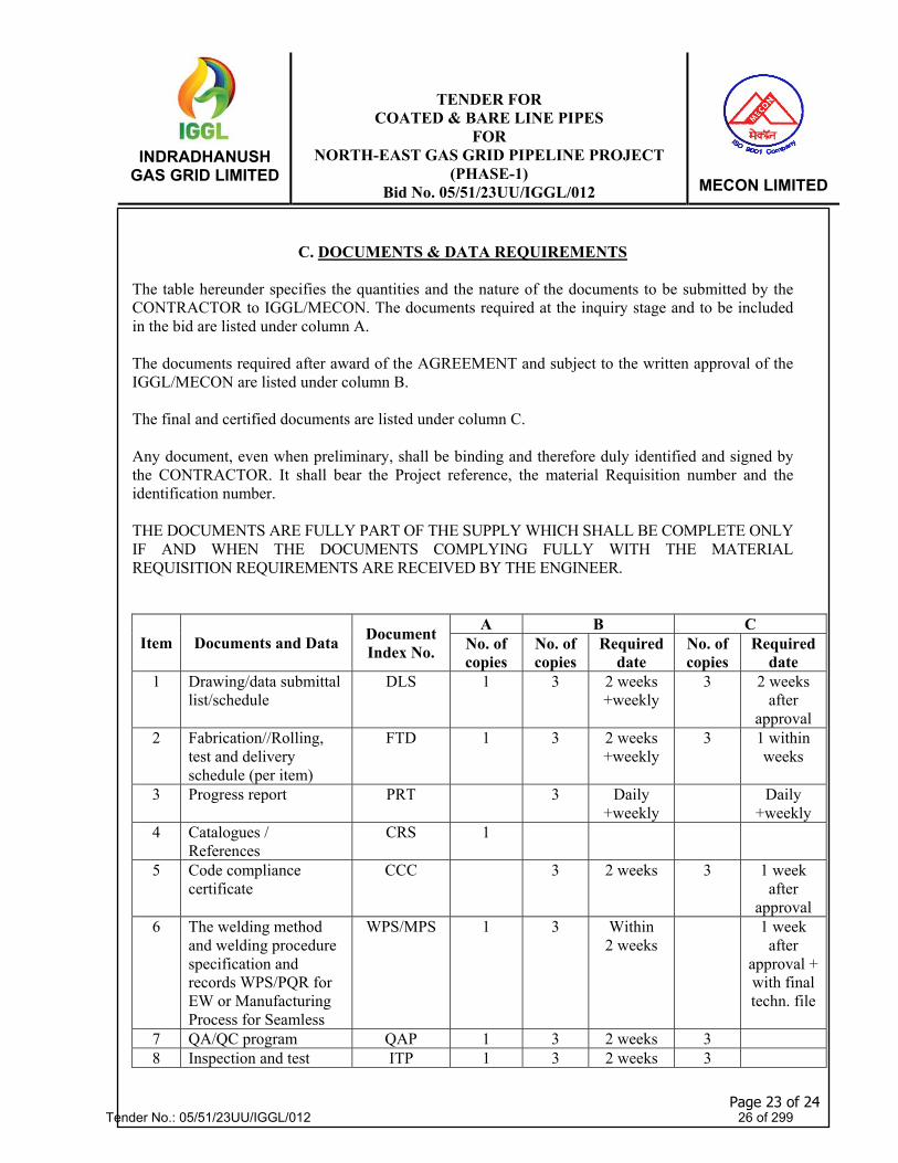
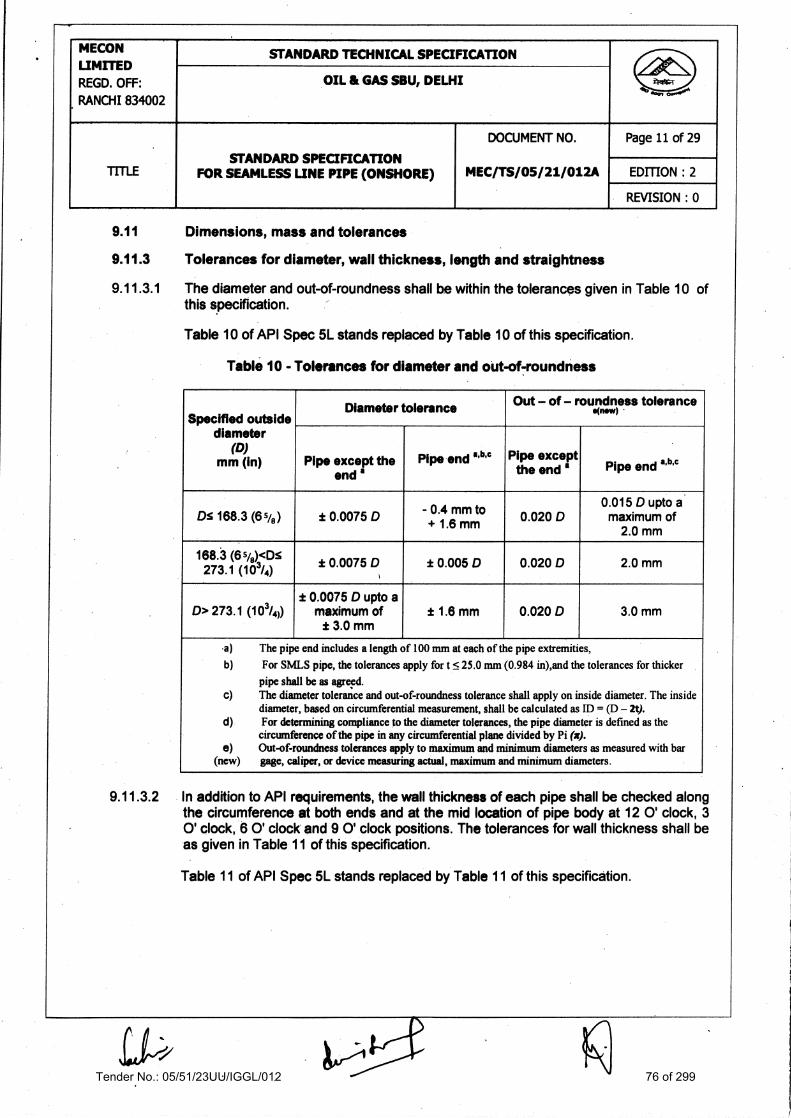
9.11.3.2
Dimensions, mass and tolerances
Tolerances for diameter, wall thickness, length and straightness
The diameter and out-of-roundness shall be within the tolerances given in Table 10 of this specification.
Table 10 of API Spec 51. stands replaced by Table 10 of this specification.
Table 10 - Tolerances for diameter and out-of-roundness
Specified outside diameter
(D) mm (in)
Diameter tolerance )
Out — of — roundness tolerance *new
Pipe except the end a
Pipe end 63),c Pipe except the end
.
Pipe end 1132 'c
Ds 168.3 (6%) ± 0.0075 D - 0.4 mm to + 1.6 mm 0.020 D
0.015 D upto a maximum of
2.0 mm .
'168.3 (6 %)<Ds 273.1 (103/4)
t 0.0075 D ± 0.005 D 0.020 D 2. mm 0
D> 273.1 (103/4)) t 0.0075 D upto a
maximum of ± 3.0 mm
± 1.6 mm 0.020 D 3.0 mm
.a) The pipe end includes a length of 100 mm at each of the pipe extremities, b) For SMLS pipe, the tolerances apply for t 5. 25.0 mm (0.984 in),and the tolerances for thicker
pipe shall be as agrepd. c) The diameter tolerance and out-of-roundness tolerance shall apply on inside diameter. The inside
diameter, based on circumferential measurement, shall be calculated as ID = (D — 2t). d) For determining compliance to the diameter tolerances, the pipe diameter is defined as the
circumference of the pipe in any circumferential plane divided by Pi (x). e) Out-of-roundness tolerances apply to maximum and minimum diameters as measured with bar
(new) gage, caliper, or device measuring actual, maximum and minimum diameters.
In addition to API requirements, the wail thickness of each pipe shall be checked along the circumference at both ends and at the mid location of pipe body at 12 0' clock, 3 0' clock, 6 0' clock and 9 0' clock positions. The tolerances for wall thickness shall be as given in Table 11 of this specification.
Table 11 of API Spec 5L stands replaced by Table 11 of this specification.
Tender No.: 05/51/23UU/IGGL/012 76 of 299

MECON
REGD. OFF: RANCHI 834002
LIMITED STANDARD TECHNICAL SPECIFICATION
c,--004 OIL & GAS MU, DELHI
TITLE STANDARD SPECIFICATION
FOR SEAMLESS LINE PIPE (ONSHORE)
DOCUMENT NO.
MEC/TS/05/21/012A
Page 12 of 29
EDITION : 2
REVISION : 0
Table 11 - Tolerances for wall thickness
Wall thickness (mm) Tolerances (mm)
t < 4.0 + 1.10 —0.00
4.0 < < 10.0 + 0.225 t
—0.00
10.0 <t< 25.0 + 0.20 t —0.00
tk 25.0 +5.00 —0.00
9.11.3.3 All pipes shall be supplied with length between 11.5 m and 12.5 m. However pipe with length between 10.0 m and 11.5 m can also be accepted for a maximum of 5% of the ordered quantity. The minimum average length of the entire ordered quantity in any case shall be 12.0 m Overall length tolerance shall be (-) Zero and (+) One pipe length to complete the ordered quantity. Table 12 of API Spec 51. stands deleted.
9.11.3.4 The tolerances for straightness shall be as follows:
a) The total deviation from a straight line over the entire pipe length shall not exceed 12 mm, as shown in Figure 1 of API Spec 5L.
b) The local deviation from straight line in 1.0 m (3.0 ft) portion at each pipe end shall be 5 3.0 mm (0.120 in), as shown in Figure 2 of API Spec 5L.
9.12 Finish of pipe ends
9.12.5 Plain ends
9.12.5.6 (New) Unless specified otherwise, the pipe ends shall be beveled as per API Spec 5L.
During removal of inside burrs at the pipe ends, care shall be taken not to remove excess metal and not to form an inside cavity on bevel. Removal of excess metal beyond the minimum wall thickness as indicated in clause 9.11.3.2 of this specification shall be a cause for re-bevelling. In case root face of bevel is less than that specified, the pipe ends shall be re-bevelled and rectification by filing or grinding shall not be done.
9.12.5.7 (New)
Bevel Protectors
Both pipe ends of each pipe shall be provided with metallic or high impact plastic bevel protectors as per Manufacturer's standard. Bevel protectors shall be of a design such that they can be re-used by coating applicator for providing on externally anti-corrosion coated pipes subsequent to coating of line pipe.
Tender No.: 05/51/23UU/IGGL/012 77 of 299

MECON LIMITED REGD. OFF: RANCH! 834002
STANDARD TECHNICAL SPECIFICATION
OIL & GAS SBU, DELHI —woo
TITLE STANDARD SPECIFICATION
FOR SEAMLESS LINE PIPE (ONSHORE)
DOCUMENT NO.
MEC/TS/05/21/012A
Page 13 of 29
EDITION : 2
REyISION : 0
INSPECTION
Types of inspection and inspection documents
Inspection documents for PSL 2pipes
Manufacturer shall issue inspection certificate 3.2 in accordance with EN 10204 for each dispatched pipe.
10.2 Specific inspection
10.2.1 Inspection frequency
10.2.1.2 For PSL 2 pipe, the inspection frequency shall be as given in Table 18 of this specification.
Table 18 of API Spec 51.. stands replaced by Table 18 of this specification.
Table 18 - Inspection frequency of pipe
S . no. Type of inspection Frequency of inspection
1. Heat analysis a One analysis per heat of steel
2. Product analysis b Two pipes per lot (maximum 100 pipes) per heat
3. Tensile testing of the pipe body C Two pipes per test unit of not more than 100
pipes per heat
4.. ,CVN impact testing of the pipe body
with specified wall thickness as given in Table 22 of API spec 5L
One set of three specimen per test unit of not . more than 100 Ives per heat
, 5. _ Vickers Hardness testing of pipe body Each specimen taken from one finished pipe from each lot (Maximum 50 pipes) per heat (see 10.2.4.8)
6. Hydrostatic testing Each pin 7. Weighing of pipe Each pipe shall be measured and recorded 8. Wall thickness measurement e Each pipe
9. Pipe diameter and out-of- roundness a Each pipe
10. Length Each length of pipe shall be measured and
recorded 11. Straightness e Each pipe
12. Visual inspection d Each pipe
13. Other dimensional testing Random testing, with the details left to the discretion of the manufacturer
Tender No.: 05/51/23UU/IGGL/012 78 of 299

14. Non-destructive inspection
In accordance with Annex E of API Spec 5L and as modified herein
a Where the steel mill is not a part of an integrated pipe mill, heat analysis shall be reported by the Manufacturer prior to start of pipe production.
b Samples used for product analysis shall be taken from finished pipes only. Pipes selected shall be such that one at the beginning of the heat and one at the end of the heat are also represented.
c Tensile test specimens shall be taken from finished pipes only. Heating or artificial ageing of tests specimens is not permitted. •
d Visual examination shall be carried out in a sufficiently illuminated area; minimum 1000 Lux. If required additional light shall be used to obtain good contrast and relief effect between imperfections and backgrounds.
e Measurement shall be recorded at least 3 times per operating shift (12 hrs maximum).
MECON LIMITED REGD. OFF: RANCHI 834002
STANDARD TECHNICAL SPECIFICATION
OIL & GAS SBU, DELHI
TITLE STANDARD SPECIFICATION
FOR SEAMLESS LINE PIPE (ONSHORE)
DOCUMENT NO.
MEC/TS/05/21/012A
Page 14 of 29
EDITION : 2
REVISION : 0
10.2.2 Samples and test pieces for product analysis
Samples shall be taken, and test pieces prepared, in accordance with ISO 14284 or ASTM E 1806. Samples used for product analysis shall be taken from finished pipes only.
10.2.3 Samples and test pieces for mechanical tests
10.2.3.1 General
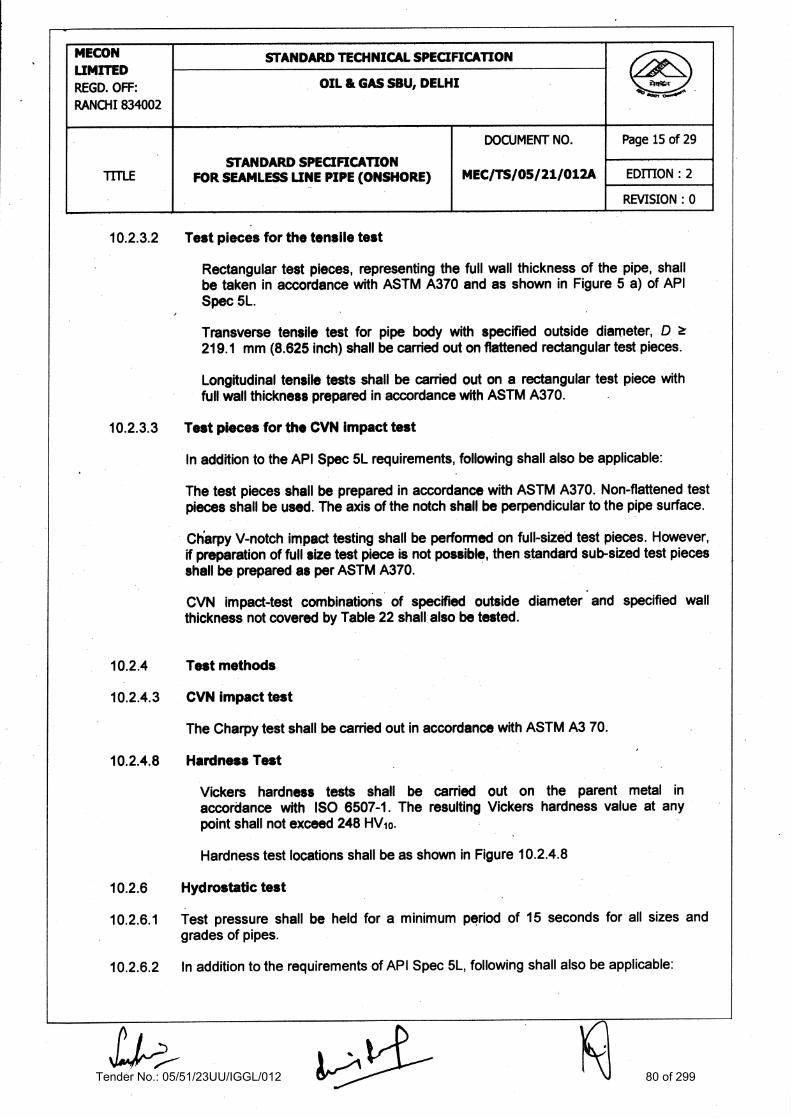
In addition to API Spec 51.. requirements, samples and test pieces for various types of tests shall be taken from Figure 5 a) of API Spec N. and Figure 10.2.4.8 of this specification, whichever is applicable, and as given in Table 20 of this specification.
Table 20 of API Spec M. stands replaced by Table 20 of this specification.
Table 20 - Number, orientation and location of test pieces per sample for mechanical tests
Sample Location
Type of test Number, Orientation and location of test *mos per samples
Pi pe body Tensile U. , IT C
CVN 3T d Hardness 1 T
a. See figure 5 (a) of API Spec 5L for an explanation of the symbols used to designate orientation and location.
b. Longitudinal tensile tests shall be carried out on a strip specimen with full wall thickness prepared according to ASTM A370.
c. The transverse tensile tests shall be carried on flattened rectangular specimen prepared according to ASTM A370 for D a 219.1mm only.
d. Test pieces shall be prepared in accordance with ASTM A370 without any prior flattening of the test material. Test specimen shall be taken from the body of the finished pipe only. Full size test specimen shall be used whenever possible.
Tender No.: 05/51/23UU/IGGL/012 79 of 299
MECON UMrTED REGD. OFF: RANCHI 834002
,
STANDARD TECHNICAL SPECIFICATION .,'
OIL & GAS SBU, DELHI
.
0-004
TITLE STANDARD SPECIFICATION
FOR SEAMLESS UNE PIPE (ONSHORE)
DOCUMENT NO.
MEC/TS/05/21/012A
Page 15 of 29
EDITION : 2
REVISION : 0
10.2.3.2 Test pieces for the tensile test
Rectangular test pieces, representing the full wall thickness of the pipe, shall be taken in accordance with ASTM A370 and as shown in Figure 5 a) of API SDec 5L.
Transverse tensile test for pipe body with specified outside diameter, D 219.1 mm (8.625 inch) shall be carried out on flattened rectangular test pieces.
Longitudinal tensile tests shall be carried out on a rectangular test piece with full wall thickness prepared in accordance with ASTM A370.
10.2.3.3 Test pieces for the CVN impact test
In addition to the API Spec 5L requirements, following shall also be applicable:
The test pieces shall be prepared in accordance with ASTM A370. Non-flaftened test pieces shall be used. The axis of the notch shall be perpendicular to the pipe surface.
Ctiatpy V-notch impact testing shall be performed on full-sized test pieces. However, if preparation of full size test piece is not possible, then standard sub-sized test pieces shall be prepared as per ASTM A370.
CVN impact-test combinations of specified outside diameter and specified wall thickness not covered by Table 22 shall also be tested.
10.2.4 Test methods
10.2.4.3 CVN impact test
The Charpy test shall be carried out in accordance with ASTM A3 70.
10.2.4.8 Hardness Test
Vickers hardness tests shall be carried out on the parent metal in accordance with ISO 6507-1. The resulting Vickers hardness value at any point shall not exceed 248 HV10.
Hardness test locations shall be as shown in Figure 10.2.4.8
10.2.6 Hydrostatic test
10.2.6.1 Test pressure shall be held for a minimum period of 15 seconds for all sizes and grades of pipes.
10.2.6.2 In addition to the requirements of API Spec 5L, following shall also be applicable:
Tender No.: 05/51/23UU/IGGL/012 80 of 299

In the event any analysis/test fails to conform to the specified requirements, manufacturer shall either reject the lot/test unit involved or test two additional lengths from same test unit. If both of the new tests conform to the specified requirements, then all the lengths in that test unit shall be accepted, with the exception of original selected length. If one or both of the retest samples fail to conform to the specified requirements, the purchaser or purchaser's representative reserves the right to either test remaining lengths in that test unit or reject the whole lot/test unit.
10.2.12 Retesting (New)
MECON LIMITED REGD. OFF: RANCHI 834002
STANDARD TECHNICAL SPECIFICATION
....0.4 OIL. & GAS SSU, DELHI
,
ITTLE STANDARD SPECIFICATION
FOR SEAMLESS UNE PIPE (ONSHORE)
DOCUMENT NO.
MEC/TS/05/21/012A
Page 16 of 29
EDITION : 2
REVISION : 0
The pressure gauge used for hydrostatic testing shall have a minimum range of 1.5 times and maximum range of 4 times the test pressure. The test-pressure measuring device shall be calibrated by means of a dead-weight tester only. The test configuration shall permit bleeding of trapped air prior to pressurization of the pipe.
10.2.6.5 The test pressure for all sizes and grades of pipe shall be such that hoop stress (fibre stress) generated is at least 95% of SMYS, computed based on the Equation (6) indicated in clause 10.2.6.5 of API Spec 5L. Table 26 of API Spec 5L stands deleted.
10.2.7 Visual inspection
Each pipe shall be visually examined for entire external surface and internal surface to the extent feasible and shall be free of _defects in finished condition. Visual examination shall be carried out in a sufficiently illuminated area; minimum 1000 lx. If required additional lights shall be used to obtain good contrast and relief effect between imperfections and backgrounds.
10.2.8 Dimensional testing
10.2.8.1 Diameter measurements shall be made with a circumferential tape only.
10.2.8.7 The measuring equipment requiring calibration or verification under the provisions of API Spec 5E. shall be calibrated with manual instruments at least once per operating shift (12 hours maximum). Such calibration records shall be furnished to Purchaser's Representative on request.
10.2.10 Non-destructive inspection
Non-destructive inspection shall be performed in accordance with Annex E of API Spec 51. and as modified herein.
10.2.11 Reprocessing Reprocessing of line pipes to meet mechanical property test results is not allowed. This clause of API Spec 5L stands cancelled.
■.■
Tender No.: 05/51/23UU/IGGL/012 81 of 299

MECON LIMITED REGD. OFF: RANCH' 834002
STANDARD TECHNICAL SPECIFICATION
OIL & GAS SBU, DELHI ....-04
TITLE STANDARD SPECIFICATION
FOR SEAMLESS LINE PIPE (ONSHORE)
DOCUMENT NO.
MEC/TS/05/21/012A
Page 17 of 29
EDITION : 2
REVISION : 0
10.2.12.1 Recheck analyses
Modalities of recheck analysis shall be as per API Spec 5L as applicable to the lot being tested (see Table 18 of this specification). However, during individual testing, each pipe shall be fully analyzed to meet the requirements of Table 5 of this specification.
11 MARKING
11.1 General
11.1.1 Pipe manufactured in accordance with this specification shall be marked by the manufacturer as per the requirements of API Spec 51.. and as modified herein. Marking shall be in English language and International System (SI) of Units:.
11.1.5 Marking shall also include API Monogram, Purchase Order number, item number, pipe (New) number and heat number.
11.2 Pipe markings
11.2.1
K) Actual length in metres and actual pipe weight in kg shall be marked. (New)
11.2.2 (New) c) Paint used for stencil marking shall withstand a temperature up to 250°C expected
to be experienced during further external anti-corrosion coating operations of line pipe by coating applicator.
11.2.3 The pipe number shall be placed by cold rolling or low stress dot marking on the outside surface of the pipe at an approximate distance of 50 mm from both ends. In case of no availability of either cold rolling or low stress dot marking facility in pipe mill, an alternative marking scheme of a permanent nature may be proposed by the Manufacturer.
11.2.7
A color code band shall be marked on inside surface of finished pipe for identification of pipes of same diameter but different .wall thickness, as indicated in the Purchase Order.
The color code band shall be 50 mm wide and shall be marked at a distance of 150 mm from the pipe ends.
12 COATINGS AND THREAD PROTECTORS
12.1.1 Unless otherwise specified in the Purchase Order, the pipes shall be delivered bare, free of any trace of oil, stain, grease and paint. Varnish coating shall be applied on the marking area. Bevels shall be free of any coating.
Tender No.: 05/51/23UU/IGGL/012 82 of 299

LIMITED REGD. OFF: RANCH! 834002
MECON
STANDARD TECHNICAL SPECIFICATION
OIL & GAS SBU, DELHI .....00
TITLE STANDARD SPECIFICATION
FOR SEAMLESS LINE PIPE (ONSHORE)
DOCUMENT NO.
MEC/TS/05/21/012A
,
Page 18 of 29
EDITION : 2
REVISION : 0
13 RETENTION OF RECORDS
14 (New)
15 (New)
In addition to the records indicated in API Spec 5L, the Manufacturer shall retain the records of all additional tests and calibration records mentioned in this specification including the hard copy records of ultrasonic testing carried out on pipe/coil as well as pipe ends.
PRODUCTION REPORT
The Manufacturer shall provide one electronic copy and six hard copies of production report in English language indicating at least the following for each pipe. International system of units (SI) shall be adopted.
- Detail of Billet/ Bloom (Heat-wise) - Pipe Number - Heat number from which pipe is produced - Pipe length and weight - Pipe grade - Consignment details.
The Manufacturer shall provide one electronic copy and six hard copies of acceptance certificates which shall include the results of all tests required as per this specification and performed on delivered material giving details of, but not limited to, the following:
All test certificates as per clause 10.1.3 of API Spec 5L and as modified herein. Certified reports of dimensional inspection, surface imperfections & defects. Data on test failures, rejected heats/lots, etc. All other reports and results required as per this specification. Copy of final inspection report with MTC. Description and disposition of repairs.
The certificates shall be valid only when signed by the Purchaser's Representative. Only those pipes, which have been certified by the Purchaser's Representative, shall be dispatched from the pipe mill.
In the event of small quantities of pipes supplied against this specification, the production report may consist of only test certificates required as per clause 10.1.3 of API Spec 5L and as modified herein and other test reports/results required as per this specification.
Online Pipe Tracking Data
Additionally, the manufacturer shall establish and follow procedures for maintaining heat and lot identity of all pipes during production. Also, it is required to have traceability of each day production.
Tender No.: 05/51/23UU/IGGL/012 83 of 299

MECON LIMITED REGD. OFF: RANCH' 834002 .
STANDARD TECHNICAL SPECIFICATION
OIL & GAS MU, DELHI ...0.4
"TULE STANDARD SPECIFICATION
FOR SEAMLESS LINE PIPE (ONSHORE)
,
DOCUMENT NO.
MEC/TS/05/21/012A
Page 19 of 29
EDITION : 2
REVISION : 0
17 •
(New)
In order to establish traceability of pipes, the system should have minimum of following information:
The manufacturer/water/supplier shall submit calculations and sketch for loading / unloading & stacking of Bare/Coated pipes at all points, e.g. warehouse/ pipe-yard (ex-works), loading and transportation on trailers, etc. as per API RP 5LT (latest edition).
In addition to the above, foreign manufacturersicoaters/suppliers shall submit calculations and sketches for loading/unloading, stacking & transportation by ship/ barge as per API RP 5LW (latest edition).
INSPECTION OF FIELD TESTS & WARRANTY
Purchaser shall be reimbursed by Manufacturer for any pipe furnished on this order that fails under field hydrostatic test if such failure is caused by a material/ manufacturing defect in the pipe. The reimbursement cost shall include pipe, labor and equipment rental for finding, excavating, cutting out and installation of replaced pipe in position . The field hydrostatic test pressure will not exceed that value which will cause a calculated hoop stress equivalent to 95 percent of specified minimum yield strength.
In case Manufacturer so desires, he will be advised at least two weeks in advance so that his Representative may witness the hydrostatic test in field, however, the testing and leak Of any) finding and repair operation shall not be postponed because of absence of the Manufacturer's Representative.
- Heat/ Billet/ Bloom number - Traceability of pipe at each station - Final status of pipe - Reason for each rejection
16 , Pipe Loading (New)
Tender No.: 05/51/23UU/IGGL/012 84 of 299

MECON LIMITED REGD. OFF: RANCH! 834002
I STANDARD TECHNICAL SPECIFICATION
OIL & GAS SBU, DELHI
STANDARD SPECIFICATION FOR SEAMLESS LINE PIPE (ONSHORE)
DOCUMENT NO.
MEC/TS/05/21/012A
Page 20 of 29 i
EDITION : 2 I I I LE
REVISION : 0
Annex B
Manufacturing Procedure Qualification for PSL 2 Pipe
B.1 INTRODUCTION
B.1.1
B. 1.2
B.1.3
This annex specifies additional provisions that apply for the PSL 2 pipes ordered as per this specification.
Two lengths, each of completely finished pipes from two different heats (i.e. a total of four pipe lengths) shall be selected at random for testing as per clause B.5.1 of this specification to verify that the manufacturing procedure results in the quality of pipes which are in complete compliance with this specification. The pipes thus tested shall be considered to be the test pipes required per heat or per lot as per relevant clauses of this specification.
These manufacturing procedure qualification tests (MPQT) shall be repeated upon any change in the manufacturing procedure as deemed necessary by Purchaser's Representative. The manufacturing procedure qualification tests shall be carried out on pipes for each wall thickness, each diameter and each grade of steel.
Verification of the manufacturing procedure shall be by qualification in accordance with clause 8.3, B.4 and B.5 of API Spec 51. and as modified herein.
Note: In the event of small quantities of pipes ordered against this specification, like those,for bends and other similar applications, as specifically called out in the Purchase Order, the manufacturing procedure qualification test as per clause B.5.1 of this specification shell not be carried out Pipes in such case shall be accepted based on regular production tests. Herwever, waiver of MPQT for any item shall be specifically as per instruction in Material Requisition (MR).
B.3 CHARACTERISTICS OF THE MANUFACTURING PROCEDURE SPECIFICATION
Before pipe production commences, Manufacturing Procedure Specification (MPS) for manufacturing of pipes and Statistical process control charts shall be prepared by pipe manufacturer (including all information as per clause B.3 a), b) and f) of API Spec 5L) and submitted for approval of the Purchaser.
B.5 MANUFACTURINGPROCEDURE QUALIFICATION TESTS (MPQT)
B.5.1 For the qualification of the manufacturing procedure, all tests & inspections specified in Table 18 and clause B.5.2 of this specification shall be conducted on all the pipes selected for testing as per clause B. 1.2 of this specification.
B.5.2 The Manufacturer shall submit to Purchaser a report giving the results of all tests mentioned below. The report shall be agreed and signed by Purchaser's Representative, prior to start of regular production.
The various tests to be conducted on each pipe shall be as follows. The test method
Tender No.: 05/51/23UU/IGGL/012 85 of 299

MECON
REGD. OFF: RANCHI 834002
LIMITED STANDARD TECHNICAL SPECIFICATION
OIL & GAS SBU, DELHI ....004
ME STANDARD SPECIFICATION
FOR SEAMLESS LINE PIPE (ONSHORE)
DOCUMENT NO.
MEC/TS/05/21/012A
Page 21 of 29
EDITION : 2
REVISION : 0
and acceptance values shall be as per this specification unless specified differently in this Annex.
a. Visual Examination
All pipes shall be examined visually for dimensional tolerances and apparent surface defects.
b. Ultrasonic Examination
All pipes shall be examined ultrasonically by automatic ultrasonic equipment.
c. Mechanical Properties
The mechanical properties of all pipes shall be tested and shall meet the requirements of this specification. Purchaser's Representative will select the places in pipe from where the test pieces shall be extracted.
The following tests shall be conducted:
i. Tensile Oft
Tensile tests as per note b & c of Table 20 shall be conducted on:
- Two (2) transverse test pieces from base material - Two (2) longitudinal test pieces from base material
ii. Fracture to$4911filps, testing
Four (4) sets of three transverse specimen shall be extracted from base metal. Test pieces shall be tested at - 40°C, - 10°C, 0°C and + 20° C for shear area and absorbed energy to produce full transition curve. The minimum average of three test pieces) shear fracture area at the test temperature specified in clause 9.8.2 of this specification shall be complied with. For other temperatures, the value shall be for information only.
Hardn946 Tiost
Hardness test shall be conducted on selected pipes as per requirement of clause 10.2.4.8 of this specification. •
Tender No.: 05/51/23UU/IGGL/012 86 of 299

MECON LIMITED REGD. OFF: RANCHI 834002
STANDARD TECHNICAL SPECIFICATION 4d 4
OIL & GAS SBU, DELHI ......0
TITLE FOR SEAMLESS LINE PIPE (ONSHORE) STANDARD SPECIFICATION
DOCUMENT NO.
MEC/TS/05/21/012A
Page 22 of 29
EDITION : 2
REVISION : 0
d. Burst Test (New)
Burst Test shall be done on each grade of pipe for each size on lowest thickness at the time of first day production test. Burst pressure & location of failure shall be recorded. Technical audit shall be carried out by OWNER / OWNER'S representative during manufacturing.
Burst pressure of the subjected pipe shall not be less than the calculated burst pressure based on the minimum actual Ultimate Tensile Strength of the subjected pipe.
Tender No.: 05/51/23UU/IGGL/012 87 of 299

MECON LIMITED REGD. OFF: RANCH! 834002
STANDARD TECHNICAL SPECIFICATION
OIL & GAS SBU, DELHI .0..0
TITLE
. i
STANDARD SPECIFICATION FOR SEAMLESS UNE PIPE (ONSHORE)
DOCUMENT NO.
MEC/TS/05/21/012A
Page 23 of 29
EDITION : 2
REVISION : 0
Annex C
Treatment of surface imperfections and defects
C.I TREATMENT OF SURFACE IMPERFECTIONS
Surface imperfection not classified as defect as per this specification shall be cosmetically dressed-out by grinding.
C.2 TREATMENTOF DRESSABLE SURFACE DEFECTS
C.2.3 Complete removal of defects shall be verified by local visual inspection and by suitable non-destructive inspection. To be acceptable, the wall thickness in the ground area shall be in accordance with clause 9.11.3.2 of this specification.
C.3 TREATMENT OF NON-DRESSABLE SURFACE DEFECT
Pipes that contain non-dressable surface defects shall be given one or more of the following dispositions.
a) Deleted
b) The sections of the pipe containing the surface defects shall be cut off, within the limits on length.
c) The entire pipe length shall be rejected.
Tender No.: 05/51/23UU/IGGL/012 88 of 299

MECON UMITED REGD. OFF: RANCHI 834002
STANDARD TECHNICAL SPECIFICATION ASe
OIL & GAS SBU, DELHI tevsa-
TITLE STANDARD SPECIFICATION
FOR SEAMLESS LINE PIPE (ONSHORE)
DOCUMENT NO.
MEC/TS/05/21/012A
_
Page 24 of 29
EDITION : 2
REVISION : 0 .
Annex E
Non-destructive inspection for other than sour service or offshore service
The Purchaser reserves the right to depute its Representative(s) to perform inspection and witness tests in all phases of manufacturing and testing starting from steel making to finished line pipe ready for shipment. Manufacturer shall comply with the provisions regarding inspection notice, plant access, compliance and rejection mentioned in the Annex Q (New) of this specification. The Manufacturer shall give the Purchaser reasonable notice of the starting date of normal production and the work schedule. Any action or omission on part of Purchaser's Representative shall not relieve the Manufacturer of his responsibility and obligation to supply material in strict accordance with this specification.
E. 1 QUALIFICATION OF PERSONNEL
E.1.1 All personnel performing NDT ictivities shall be qualified in the technique applied, in accordance with latest edition of ISO 9712, ISO 11484 or ASNT No. ASNT-TC-1A or equivalent •
All NOT shall be performed in accordance with written procedures. , These procedures shall have prior approval of the Purchaser.
Ipspopctor Qua/4110*ln Acceptable qua Ification for NDT inspectors shall be as specified below:
(0 For UT
For UT, at least one Level III qualified inspector shall be available to the mill for overall supervision. Level III inspectors shall be ASNT Level III or ACCP Professional Level III and certified in applicable method.
A level II inspector is required for shift supervision and calibration of all systems (both manual and automated).
(ii) For all other NOT methods
Evaluation of Indications : Level II & Level III inspector Shift Supervisor : Level II inspector
E.3 METHODS OF INSPECTION
E.3.1 General
E.3.1.1 All seamless pipes shall be non-destructively inspected for full length (100%) in accordance with applicable method given in Table E.2 of API Spec 5L
using automatic ultrasonic equipment in accordance with clause E.5 of API . Spec 5L and as modified in this specification.
Tender No.: 05/51/23UU/IGGL/012 89 of 299

MECON LIMITED REGD. OFF: RANCHI 834002
STANDARD TECHNICAL SPECIFICATION
OIL & GAS SBU, DELHI ...we
STANDARD SPECIFICATION
FOR SEAMLESS LINE PIPE (ONSHORE)
DOCUMENT NO.
MEC/TS/05/21/012A
Page 25 of 29
EDITION : 2 I I I LE
REVISION : 0
E.3.3 Pipe End Inspection-1MS pipe
E3.3.1 Pipe ends not covered by automatic ultrasonic equipment shall be inspected by manual ultrasonic equipment with same sensitivity and capability as automatic equipment, or, such non—inspected pipe end shall be cut—off. Records in accordance with E.5.4 of API Spec R. shall be maintained.
E3.3.2 Ultrasonic inspection in accordance with ISO 10893-8 shall be used to verify that the 50 mm (2.0 in) wide zone at each pipe end is free of such laminar defects. Pipe ends. not covered by automatic ultrasonic equipment shall be either cut—off or inspected by manual ultrasonic equipment with same sensitivity and capability as automatic equipment.
E3.3.3 Any lamination or inclusion either extending into the face or bevel of the pipe or present (New) within 50 mm of pipe ends is classified as defects and treated in accordance with
clause E.10 (e) or (0 of API Spec 5L.
E3.3.4 • Bevel face of each pipe end shall be magnetic particle inspected for the detection of (New) laminar imperfections in accordance with ISO 10893-5. ,
E.5 ULTRASONIC AND ELECTROMAGNETIC INSPECTION
E.5.1 Equipment
E.5.1 .3(New) In addition to the API Spec 5L requirements, all automatic ultrasonic equipment shall have an alarm device, which continuously monitors the effectiveness of the coupling. The equipment for the automatic inspection shall allow the localization of both longitudinal and transverse defects corresponding to the signals exceeding the acceptance limits of the reference standard. The equipment shall be fitted with a paint spray or automatic marking device and alarm device for areas g lying unacceptable ultrasonic indications. All ultrasonic testing equipment shall be provided with recording device.
E.5.2 Ultrasonic and electromagneticinspection reference standards
E.5.2.1 The reference standard (calibration pipe) shall have the same specified diameter and wall thickness as specified for the production pipe being inspected.
E.5.2.2 Reference standards shall be of sufficient length to permit calibration of ultrasonic inspection equipment at the speed to be used in normal production.
The reference standard (calibration pipe) shall also be of the same material, type and have the same surface finish and heat treatment as the pipe being inspected.
Tender No.: 05/51/23UU/IGGL/012 90 of 299
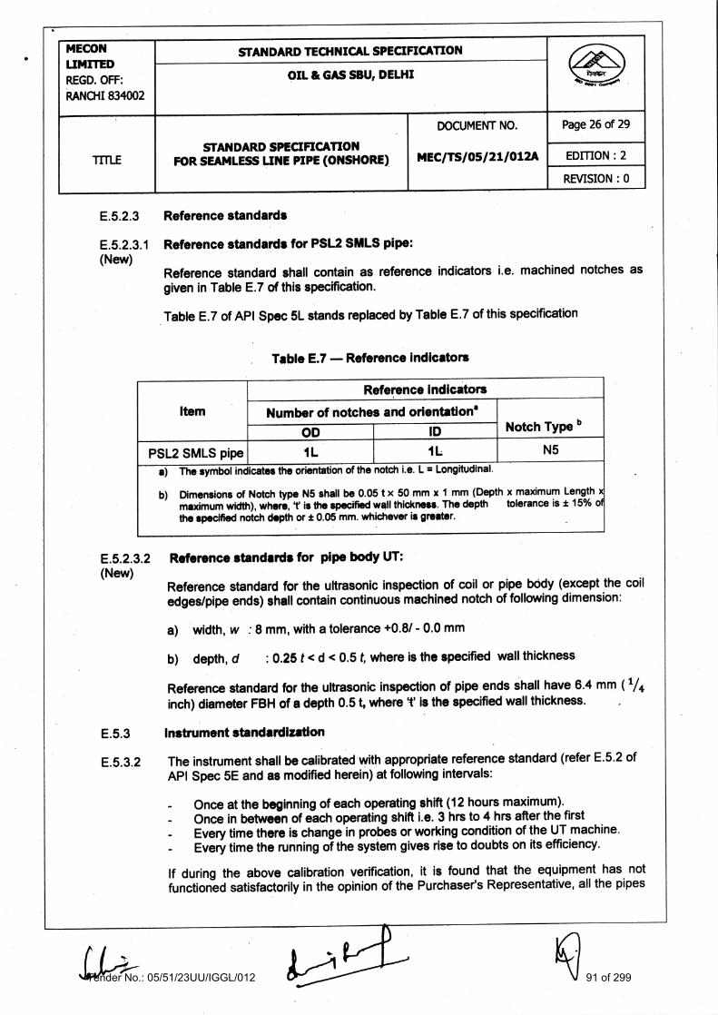
Reference Indicators
Item
Number of notches and orientation*
OD
ID Notch Type b
PSL2 SMLS pipe
1L
N5
a) The symbol indicates the orientation of the notch i.e. L = Longitudinal.
b) Dimensions of Notch type N5 shall be 0.05 t x 50 mm x 1 mm (Depth x maximum Length x maximum width), where, T is the specified wall thickness. The depth tolerance is t 15% of the specified notch depth or t 0.05 mm. whichever is greater.
•
MECON LIMITED REGD. OFF: RANCHI 834002
STANDARD TECHNICAL SPECIFICATION ,
OIL & GAS SOU, DELHI ....00
TITLE STANDARD SPECIFICATION
FOR SEAMLESS LINE PIPE (ONSHORE)
DOCUMENT NO.
MEC/TS/05/21/012A
Page 26 of 29
EDITION : 2
REVISION : 0
E.5.2.3 Reference standards
E.5.2.3.1 Reference standards for PSL2 SMLS pipe: (New)
Reference standard shall contain as reference indicators i.e. machined notches as given in Table E.7 of this specification.
Table E.7 of API Spec 51.. stands replaced by Table E.7 of this specification
Table E.7 Reference indicators
E.5.2.3.2 Reference standards for pipe body UT: (New)
Reference standard for the ultrasonic inspection of coil or pipe bOdy (except the coil edges/pipe ends) shall contain continuous machined notch of following dimension:
a) • width, w : 8 mm, with a tolerance +0.8/ - 0.0 mm
b) depth, d : 0.25 t < d < 0.5 t, where is the specified wall thickness
Reference standard for the ultrasonic inspection of pipe ends shall have 6.4 mm ( 1/4
inch) diameter FBH of a depth 0.5 t, where 1' is the specified wall thickness.
E.5.3 Instrument standardization
E.5.3.2 The instrument shall be calibrated with appropriate reference standard (refer E.5.2 of API Spec 5E and as modified herein) at following intervals:
Once at the beginning of each operating shift (12 hours maximum). Once in between of each operating shift i.e. 3 hrs to 4 hrs after the first Every time there is change in probes or working condition of the UT machine. Every time the running of the system gives rise to doubts on its efficiency.
If during the above calibration verification, it is found that the equipment has not functioned satisfactorily in the opinion of the Purchaser's Representative, all the pipes
Tender No.: 05/51/23UU/IGGL/012 91 of 299

MECON LIMITED REGD. OFF: RANCHI 834002
STANDARD TECHNICAL SPECIFICATION
OIL & GAS SBU, DELHI
TITLE
•
STANDARD SPECIFICATION FOR SEAMLESS LINE PIPE (ONSHORE)
DOCUMENT NO.
MEC/TS/05/ 21/012A
Page 27 of 29
EDITION : 2
REVISION : 0
or coils already inspected after the previous verification shall be inspected again at Manufacturer's cost.
E. 5.5 Acceptance limits
E.5.5.4 For all examination types, indications exceeding the acceptance limit signals are unacceptable. For lamination detection in seamless pipe body and pipe ends, the acceptance limits shall be based on the lamination size and frequency as given below:
Any lamination in the body of the pipe exceeding both of the following is considered a defect:
a) Greater than or equal to 12.0 mm in the minor dimension b) Greater than or equal to 5000 mm 2 in area.
E.5.6 Disposition of defects found by ultrasonic and electromagnetic inspection
Disposition of any imperfection in pipe that produces an indication greater than the acceptable limits as specified in this specification shall be classified as defect and shall be given disposition as specified in (e) or (f) of E.10 of API Spec 5L.
E.7 • RESIDUAL MAGNETISM
E.7.2 The longitudinal magnetic field shall be measured on all sizes of pipes. Measurement on pipe in stack shall not be considered valid..
E.7.3 Measurements shall be made using Hall - effect gauss-meter only.
E.7.4 Measurements shall be made on each end of a pipe for 5% of the pipes produced but at least once per 4 hr per operating shift (12 hrs maximum).
E.7.6 Four readings shall be taken approximately 90° apart around the circumference of each end of the pipe. The average of the four readings shall not exceed 2.0 mT (20 gauss) and no single reading shill exceed 2.5 mT (25 gauss). All residual magnetism measurements shall be recorded.
E.10 DISPOSITION OF PIPES CONTAINING DEFECTS
c) The repaired area shall be 100% rechecked by magnetic particle or ultrasonic inspection to ensure complete removal of defects. However for repair of cosmetic type of defects, MPI may not be conducted if so directed by Purchaser's Representative on case to case basis. The pipes having a thickness less than the minimum allowed in accordance with this specification, after repair by grinding shall be treated for disposition in accordance with (e) or (f) of clause E. 10 of API Spec 5L.
Tender No.: 05/51/23UU/IGGL/012 92 of 299

MECON LIMITED REGD. OFF: RANCHI 834002
STANDARD TECHNICAL SPECIFICATION
OIL & GAS SBU, DELHI
, ....00
...
TITLE
—
STANDARD SPECIFICATION FOR SEAMLESS LINE PIPE (ONSHORE)
DOCUMENT NO.
MEC/TS/05/21/012A
Page 28 of 29
EDITION : 2
REVISION : 0
Annex Q (New)
Purchaser Inspection
Q.1 INSPECTION NOTICE
Advance notice shall be given by the manufacturer prior to the start of production to thepurchaser to inspect/ witness the manufacturing activities including tests.
Q.2 PLANT ACCESS
The inspector representing the purchaser shall have unrestricted access, at all times while work of the contract of the purchaser is being performed, to all parts of the manufacturer's works that will concern the manufacture of the pipe ordered. The manufacturer shall afford the inspector all reasonable facilities to satisfy the inspector that the pipe is being manufactured in accordance with this specification. All inspections should be made at the place of manufacture prior to shipment, unless otherwise specified on the purchase order, and shall be so conducted as not to interfere unnecessarily with the operation of the works.
Q.3 CCMIPLIANCE
The manufacturer is responsible for complying with all of the provisions of this specification. The purchaser may make any investigation necessary to be satisfied of compliance by the manufacturer and any reject any material that does not comply with this specification.
Q.4 REJECTION
If the Purchaser Representative rejects pipes repeatedly for any recurring cause, this shall be adequate reason to refuse final inspection of subsequent pipes until the cause has been investigated and corrective action taken by the Manufacturer.
Tender No.: 05/51/23UU/IGGL/012 93 of 299

1 • • mm
............. ........ . . . . .. .... . .• ... -4.111 ....
........... 1/2 WT" •
...... ........ ...... .... mm .... I .
. . .................:...........H ...........
..................... ....... .....
. ................
...........
.........................
•
*** 5 mm I
..... _S.. ....... • .....
MECON LIMITED REGD. OFF: RANCHI 834002
STANDARD TECHNICAL SPECIFICATION Are
OIL & GAS SBU, DELHI ..., .....-
TITLE STANDARD SPECIFICATION
FOR SEAMLESS LINE PIPE (ONSHORE)
DOCUMENT NO.
MEC/TS/OS/21/012A
Page 29 of 29
EDITION : 2
REVISION : 0
Notes:
1. Number of hardness measurement required on each specimen shall be min. 12 at the dotted lines intersection locations
FIGURE: 10.2.4.8
LOCATIONS FOR HARDNESS MEASUREMENT
k
Tender No.: 05/51/23UU/IGGL/012 94 of 299

Tender No.: 05/51/23UU/IGGL/012 95 of 299

Tender No.: 05/51/23UU/IGGL/012 96 of 299

Tender No.: 05/51/23UU/IGGL/012 97 of 299

Tender No.: 05/51/23UU/IGGL/012 98 of 299

Tender No.: 05/51/23UU/IGGL/012 99 of 299
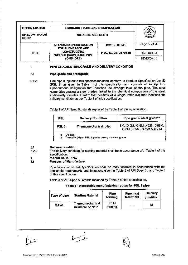
Tender No.: 05/51/23UU/IGGL/012 100 of 299

Tender No.: 05/51/23UU/IGGL/012 101 of 299

Tender No.: 05/51/23UU/IGGL/012 102 of 299

Tender No.: 05/51/23UU/IGGL/012 103 of 299
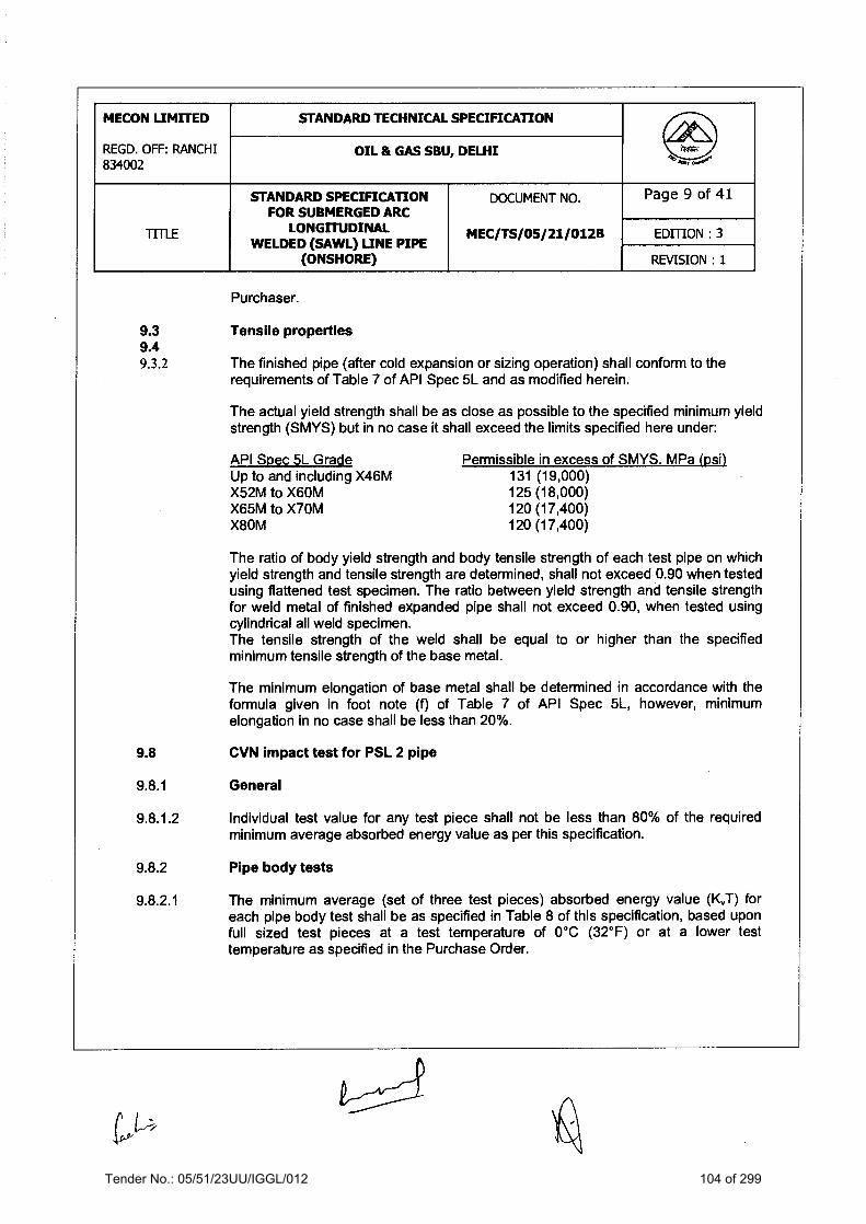
Tender No.: 05/51/23UU/IGGL/012 104 of 299

Tender No.: 05/51/23UU/IGGL/012 105 of 299

Tender No.: 05/51/23UU/IGGL/012 106 of 299
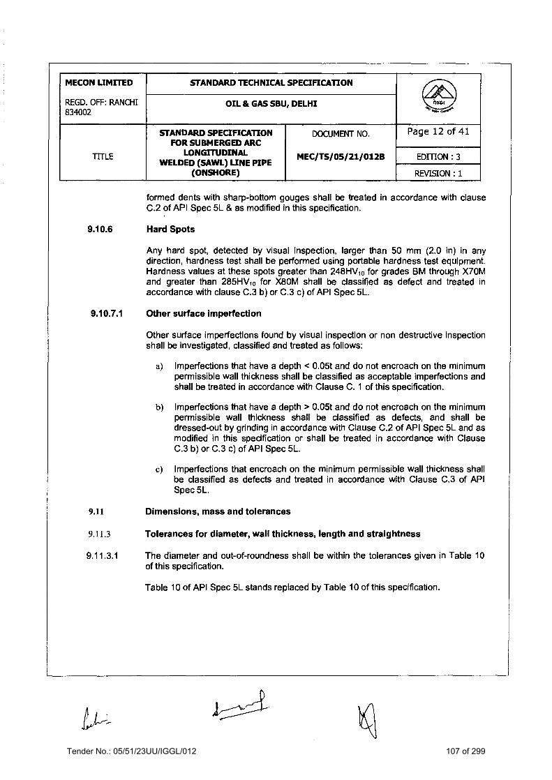
Tender No.: 05/51/23UU/IGGL/012 107 of 299

Tender No.: 05/51/23UU/IGGL/012 108 of 299

Tender No.: 05/51/23UU/IGGL/012 109 of 299

Tender No.: 05/51/23UU/IGGL/012 110 of 299

Tender No.: 05/51/23UU/IGGL/012 111 of 299

Tender No.: 05/51/23UU/IGGL/012 112 of 299

Tender No.: 05/51/23UU/IGGL/012 113 of 299

Tender No.: 05/51/23UU/IGGL/012 114 of 299

Tender No.: 05/51/23UU/IGGL/012 115 of 299

Tender No.: 05/51/23UU/IGGL/012 116 of 299

Tender No.: 05/51/23UU/IGGL/012 117 of 299

Tender No.: 05/51/23UU/IGGL/012 118 of 299

Tender No.: 05/51/23UU/IGGL/012 119 of 299

Tender No.: 05/51/23UU/IGGL/012 120 of 299

Tender No.: 05/51/23UU/IGGL/012 121 of 299

Tender No.: 05/51/23UU/IGGL/012 122 of 299

Tender No.: 05/51/23UU/IGGL/012 123 of 299

Tender No.: 05/51/23UU/IGGL/012 124 of 299

Tender No.: 05/51/23UU/IGGL/012 125 of 299

Tender No.: 05/51/23UU/IGGL/012 126 of 299

Tender No.: 05/51/23UU/IGGL/012 127 of 299

Tender No.: 05/51/23UU/IGGL/012 128 of 299

Tender No.: 05/51/23UU/IGGL/012 129 of 299

Tender No.: 05/51/23UU/IGGL/012 130 of 299

Tender No.: 05/51/23UU/IGGL/012 131 of 299

Tender No.: 05/51/23UU/IGGL/012 132 of 299

Tender No.: 05/51/23UU/IGGL/012 133 of 299

Tender No.: 05/51/23UU/IGGL/012 134 of 299

Tender No.: 05/51/23UU/IGGL/012 135 of 299

Tender No.: 05/51/23UU/IGGL/012 136 of 299

Tender No.: 05/51/23UU/IGGL/012 137 of 299

Tender No.: 05/51/23UU/IGGL/012 138 of 299

Tender No.: 05/51/23UU/IGGL/012 139 of 299

Tender No.: 05/51/23UU/IGGL/012 140 of 299

Tender No.: 05/51/23UU/IGGL/012 141 of 299

Tender No.: 05/51/23UU/IGGL/012 142 of 299

Tender No.: 05/51/23UU/IGGL/012 143 of 299

Tender No.: 05/51/23UU/IGGL/012 144 of 299

Tender No.: 05/51/23UU/IGGL/012 145 of 299

Tender No.: 05/51/23UU/IGGL/012 146 of 299

Tender No.: 05/51/23UU/IGGL/012 147 of 299

Tender No.: 05/51/23UU/IGGL/012 148 of 299

Tender No.: 05/51/23UU/IGGL/012 149 of 299

Tender No.: 05/51/23UU/IGGL/012 150 of 299

Tender No.: 05/51/23UU/IGGL/012 151 of 299

Tender No.: 05/51/23UU/IGGL/012 152 of 299

Tender No.: 05/51/23UU/IGGL/012 153 of 299

Tender No.: 05/51/23UU/IGGL/012 154 of 299

Tender No.: 05/51/23UU/IGGL/012 155 of 299

Tender No.: 05/51/23UU/IGGL/012 156 of 299

Tender No.: 05/51/23UU/IGGL/012 157 of 299

Tender No.: 05/51/23UU/IGGL/012 158 of 299

Tender No.: 05/51/23UU/IGGL/012 159 of 299

Tender No.: 05/51/23UU/IGGL/012 160 of 299

Tender No.: 05/51/23UU/IGGL/012 161 of 299

Tender No.: 05/51/23UU/IGGL/012 162 of 299

Tender No.: 05/51/23UU/IGGL/012 163 of 299

Tender No.: 05/51/23UU/IGGL/012 164 of 299

Tender No.: 05/51/23UU/IGGL/012 165 of 299

Tender No.: 05/51/23UU/IGGL/012 166 of 299

Tender No.: 05/51/23UU/IGGL/012 167 of 299

Tender No.: 05/51/23UU/IGGL/012 168 of 299

Tender No.: 05/51/23UU/IGGL/012 169 of 299

Tender No.: 05/51/23UU/IGGL/012 170 of 299

Tender No.: 05/51/23UU/IGGL/012 171 of 299

Tender No.: 05/51/23UU/IGGL/012 172 of 299

Tender No.: 05/51/23UU/IGGL/012 173 of 299

Tender No.: 05/51/23UU/IGGL/012 174 of 299

Tender No.: 05/51/23UU/IGGL/012 175 of 299

Tender No.: 05/51/23UU/IGGL/012 176 of 299

Tender No.: 05/51/23UU/IGGL/012 177 of 299

Tender No.: 05/51/23UU/IGGL/012 178 of 299

Tender No.: 05/51/23UU/IGGL/012 179 of 299

Tender No.: 05/51/23UU/IGGL/012 180 of 299

SPECIFICATION
FOR 3-LAYER POLYETHYLENE COATING OF LINEPIPES
SPECIFICATION NO.: MEC/S/05/21/014
(OIL & GAS SBU) MECON LIMITED DELHI 110 092
Rev. : 0 Edition : 1
Tender No.: 05/51/23UU/IGGL/012 181 of 299

MECON LIMITED REGD. OFF: RANCHI 834002
STANDARD TECHNICAL SPECIFICATION
OIL & GAS SBU, DELHI
DOCUMENT NO. Page 1 of 1
TITLE 3-LAYER POLYETHYLENE COATING OF LINEPIPES
MEC/S/05/21/014 REVISION : 0
EDITION : 1
G:\B Drive\E drive\2014 GAIL\JHPL Phase -1\Volume II of II\014 - 3-LPE Coating of Linepipes- Edt.1-Dec 08.doc
C O N T E N T S
1.0 SCOPE 2.0 REFERENCE DOCUMENTS 3.0 PLANT SCALE AND INSTALLATION 4.0 MATERIALS 5.0 FUNCTIONAL REQUIREMENTS AND PROPERTIES OF COATING 6.0 MEASUREMENT AND LOGGING 7.0 COATING PROCEDURE AND QUALIFICATION 8.0 PIPE SURFACE PREPARATION 9.0 COATING APPLICATION 10.0 INSPECTION AND TESTING 11.0 HANDLING, TRANSPORTATION AND STORAGE 12.0 REPAIR OF COATING 13.0 MARKING 14.0 QUALITY ASSURANCE ANNEXURE-I : COMBINATION OF COATING MATERIALS PREPARED BY:
(A.K. Nimbekar)
CHECKED BY:
(Vinod Kumar)
APPROVED BY:
(A.K. Johri)
ISSUE DATE :
Feb. 2008
Tender No.: 05/51/23UU/IGGL/012 182 of 299

MECON LIMITED REGD. OFF: RANCHI 834002
STANDARD TECHNICAL SPECIFICATION
OIL & GAS SBU, DELHI
DOCUMENT NO. Page 1 of 1
TITLE 3-LAYER POLYETHYLENE COATING OF LINEPIPES
MEC/S/05/21/014 REVISION : 0
EDITION : 1
G:\B Drive\E drive\2014 GAIL\JHPL Phase -1\Volume II of II\014 - 3-LPE Coating of Linepipes- Edt.1-Dec 08.doc
AMENDMENT STATUS
Sl. No.
Clause / Paragraph / Annexure / Exhibit / Drawing Amended
Page No.
Revision Date By (Name)
Verified (Name)
Tender No.: 05/51/23UU/IGGL/012 183 of 299

MECON LIMITED REGD. OFF: RANCHI 834002
STANDARD TECHNICAL SPECIFICATION
OIL & GAS SBU, DELHI
DOCUMENT NO. Page 1 of 33
TITLE 3-LAYER POLYETHYLENE COATING OF LINEPIPES
MEC/S/05/21/014 REVISION : 0
EDITION : 1
G:\B Drive\E drive\2014 GAIL\JHPL Phase -1\Volume II of II\014 - 3-LPE Coating of Linepipes- Edt.1-Dec 08.doc
1.0 SCOPE This specification covers the minimum requirements for supply/ arrangement of all
materials, plant, equipment, plant sites, consumables, utilities and application including all labour, supervision, inspection and tests etc. for application of external anti-corrosion coating of pipes by using 3 Layer Side Extruded Polyethylene Coating conforming to DIN-30670, 1991, `Polyethylene Coating of Steel Pipes and Fittings' and the requirements of this specification.
2.0 REFERENCE DOCUMENTS Reference has also been made to the latest edition of the following standards, codes
and specifications. The edition enforce at the time of floating the enquiry shall be termed as latest edition.
a. ASTM D-149 : Standard Test Methods of Dielectric Breakdown
voltage and Dielectric strength of solid electrical insulating materials at commercial frequencies.
b. ASTM D-257 : Standard Test Methods for D-C Resistance or
conductance of insulating materials. c. ASTM D-543 : Standard Method of Test for Ressistance of
Plastics to Chemical Reagents. d. ASTM D-570 : Standard Method of Test for Water Absorption of
Plastics. e. ASTM D-638 : Standard Test Method for Tensile
Properties of Plastics. f. ASTM D-792 : Standard Test Method of Specific Gravity and
Density of Plastics by Displacement. g. ASTM D-1238 : Test Method for Low Rate of Thermoplastics by Extrusion.
h. ASTM D-1525 : Test Method for Vicat Softening Temperature of Plastics i. ASTM D-1603 : Test Method for Carbon Black in Olefin
Plastics j. ASTM D-1693 : Test Method for Environmental Stress Cracking of Ethylene Plastics k. ASTM D-2240 : Test Method for Rubber Property – Durometer Hardness
Tender No.: 05/51/23UU/IGGL/012 184 of 299

MECON LIMITED REGD. OFF: RANCHI 834002
STANDARD TECHNICAL SPECIFICATION
OIL & GAS SBU, DELHI
DOCUMENT NO. Page 2 of 33
TITLE 3-LAYER POLYETHYLENE COATING OF LINEPIPES
MEC/S/05/21/014 REVISION : 0
EDITION : 1
G:\B Drive\E drive\2014 GAIL\JHPL Phase -1\Volume II of II\014 - 3-LPE Coating of Linepipes- Edt.1-Dec 08.doc
l. ASTM D-3895 : Test Method for Oxidative – Induction Time of Polyolefins by Differential Scanning Calorimetry
m. ASTM G-42 : Tentative Methods for Cathodic disbonding of
Pipeline Coatings Subjected to Elevated or Cyclic Temperatures.
n. API RP 5L1 : Recommended Practice for Railroad
Transportation of Linepipe. o. API RP 5LW : Transportation of Line Pipe on barges and
marine vessels p. DIN EN 10204 : Metallic Products – Types of Inspection
Documents q. DIN 53735 : Testing of Plastics : Determination of Melt Index
of Thermoplastics. r. ISO 8502-3 : Preparation of Steel Stubstrates before
Application of Paints and Related Products – Part-3 – Assessment of Dust on Steel Surfaces Prepared for Painting (Pressure Sensitive Tape Method)
s. ISO 9002 : Quality Systems : Specification of Production and
Installation t. ISO 11124 : Preparation of Steel Substrates Before
Application of Paints and Related Products u. SIS 055900 : Preparation of Steel Substrates before
Application of Paints and Related Products – Visual Assessment of Surface Cleanliness.
v. APL 5L : Specification for Line Pipe w. ASME B 31.8 : Gas Transmission and Distribution
Piping Systems
x. ASME B 31.4 : Liquid Transportation systems for Hydrocarbons, Liquid petroleum Gas Anhydrous ammonia, and Alcohols
y. CSA Z245.20-98 : External Fusion Bond Epoxy Coating for
Steel Pipe
Tender No.: 05/51/23UU/IGGL/012 185 of 299

MECON LIMITED REGD. OFF: RANCHI 834002
STANDARD TECHNICAL SPECIFICATION
OIL & GAS SBU, DELHI
DOCUMENT NO. Page 3 of 33
TITLE 3-LAYER POLYETHYLENE COATING OF LINEPIPES
MEC/S/05/21/014 REVISION : 0
EDITION : 1
G:\B Drive\E drive\2014 GAIL\JHPL Phase -1\Volume II of II\014 - 3-LPE Coating of Linepipes- Edt.1-Dec 08.doc
The CONTRACTOR shall be familiar with the requirements of these documents and
shall make them readily available at the coating plant to all persons concerned with carrying out the works specified in this specification.
3.0 PLANT SCALE AND INSTALLATION 3.1 CONTRACTOR shall size coating plant(s) after evaluating the scale of work and the
time schedule required for the works. Coating plant(s), both new or existing shall be installed into a yard whose geometry and dimensions are such as to allow the execution of a continuous work schedule. For this purpose the CONTRACTOR shall ensure non stop work execution owing to prohibitive adverse weather conditions and install requisite equipment and plant in roofed and adequately weather protected areas.
3.2 Plant equipment, machinery and other facilities shall be in first class operating
condition to atleast meet the job requirements of quality and production. Worn out and improvised plants are not acceptable.
3.3 The CONTRACTOR shall, at his own responsibility and cost, provide and prepare all
necessary area for the storage of bare and coated pipe and all other materials, for coating yard, stock-piling and other temporary installation. For each area, CONTRACTOR shall provide necessary agreements as required with the land Owner(s) / relevant Authorities, and, on work completion, to clean, restore and pay servitude and claims for damages, as applicable.
3.4 CONTRACTOR shall at its own responsibility and cost, provide for water and power
supply and other utilities and consumables and obtain authorisation regarding access roads and other permits required for the execution of works conforming to all the requirements of the governing authorities.
3.5 CONTRACTOR shall at its own expense provide a fully equipped laboratory and test
facilities with adequate inventory to carry out tests required for the procedure qualification and during regular production. Outside testing for qualification and regular production is not acceptable to COMPANY.
3.6 The CONTRACTOR shall be fully responsible for adherence to all statutory regulations
applicable for handling and disposal of the hazardous chemicals during the coating works.
3.7 The CONTRACTOR shall be responsible for obtaining all statutory approvals/ clearances
from relevant Authorities including Pollution Control Board, as applicable for the coating plant(s).
Tender No.: 05/51/23UU/IGGL/012 186 of 299

MECON LIMITED REGD. OFF: RANCHI 834002
STANDARD TECHNICAL SPECIFICATION
OIL & GAS SBU, DELHI
DOCUMENT NO. Page 4 of 33
TITLE 3-LAYER POLYETHYLENE COATING OF LINEPIPES
MEC/S/05/21/014 REVISION : 0
EDITION : 1
G:\B Drive\E drive\2014 GAIL\JHPL Phase -1\Volume II of II\014 - 3-LPE Coating of Linepipes- Edt.1-Dec 08.doc
4.0 MATERIALS 4.1 The three layer coating system shall comprise of a powder epoxy primer, polymeric
adhesive and a polyethylene top coat. Coating materials shall be suitable for the service conditions and the pipe sizes involved. The coating materials i.e. epoxy powder, adhesive and polyethylene compound shall have proven compatibility. The coating system and materials shall be pre-qualified and approval COMPANY in accordance with provision Annexure-I of this specification. CONTRACTOR shall obtain prior approval from COMPANY for the coating system and coating of all materials.
4.2 The coating materials Manufacturer shall carry out tests for all properties specified in
para 5.3.1 and 5.3.2 for each batch of epoxy, adhesive and polyethylene compound. In addition, the Manufacturer shall also furnish Infra-red Scan for each batch of epoxy powder. The coating materials manufacturer shall issue test certificates as per DIN EN 10204, 3.1B for each batch of materials supplied to CONTRACTOR and the same shall be submitted to COMPANY for approval prior to their use.
4.3 In addition to Manufacturer’s certificate, the CONTRACTOR shall draw samples from
each batch of epoxy, adhesive and polyethylene in the presence of COMPANY Representative and test for the following properties at the coating yard at least one week prior to its use, to establish compliance with the Manufacturer’s certificates.
a) Epoxy Powder
i. Gel Time ii. Cure Time iii. Moisture Content iv. Thermal Characteristics (Tg1, Tg2, ∆H)
b) Adhesive
i. Specific Gravity ii. Melt Flow Rate iii. Vicat Softening Point
c) Polyethylene
i. Melt Flow Rate ii. Specific Gravity iii. Vicat Softening Point iv. Moisture Content v. Oxidative Induction Time
In case of failure of any of the above tests in a batch, that batch of material shall be
tested for all other tests required as per para 5.3.1 and 5.3.2 including the tests which failed. If all tests pass, the batch shall be accepted for coating. If any of the tests fail, entire batch of material shall be rejected and shall not be used for the coating.
Tender No.: 05/51/23UU/IGGL/012 187 of 299

MECON LIMITED REGD. OFF: RANCHI 834002
STANDARD TECHNICAL SPECIFICATION
OIL & GAS SBU, DELHI
DOCUMENT NO. Page 5 of 33
TITLE 3-LAYER POLYETHYLENE COATING OF LINEPIPES
MEC/S/05/21/014 REVISION : 0
EDITION : 1
G:\B Drive\E drive\2014 GAIL\JHPL Phase -1\Volume II of II\014 - 3-LPE Coating of Linepipes- Edt.1-Dec 08.doc
4.4 All materials to be used shall be supplied in sealed, damage free containers and shall be suitably marked and identifiable with the following minimum information:
a. Name of the manufacturer b. Type of material c. Batch Number d. Place and Date of Manufacture
e. Shelf Life/ Expiry Date (if applicable) f. Quantity
All materials noted to be without above identification shall be deemed suspect and
shall be rejected by COMPANY. Such materials shall not be used for coating and shall be removed from site and replaced by CONTRACTOR at its expense.
4.6 CONTRACTOR shall ensure that all coating materials properly stored in accordance
with the Manufacturer’s recommendation at all times, to prevent damage and deterioration in quality prior to use.
4.7 CONTRACTOR shall be required to use all materials on a date received rotation basis,
i.e. first in-first used basis. 5.0 FUNCTIONAL REQUIREMENTS AND PROPERTIES OF COATING 5.1 The coating must be able to withstand a maximum in service operating temperature of
+65°C and shall conform to `S’ Type of coating as per DIN 30670. In addition, in open storage the coating must be able to withstand a temperature of atleast +80°C, without impairing its serviceability and properties specified.
5.2 The top coat polyethylene used shall be black readymade compound, fully stabilized
against influence of ultraviolet radiation (.e. sunlight), oxygen in air and heat (due to environmental temperature as specified above). No appreciable changes shall occur during exposure to such environments up to at least a period of 6000 hours. The CONTRACTOR shall submit certificate from Manufacturer in this regard.
5.3 Properties
Properties of coating system and coating material shall comply the requirements indicated in subsequent paragraph. In case the coating/ material properties are tested as per test methods/ standards other than specified herein below, the same may be accepted provided the test procedures and test conditions are same or more stringent than the specified.
5.3.1 Properties of Epoxy Powder and Adhesive CONTRACTOR shall choose such a brand of epoxy powder and adhesive that will
achieve the functional requirements and properties of coating system as specified in para 5.1 and 5.3.3 of this specification respectively. Epoxy powder properties shall be as per CSA Z245.20.98. The colour of epoxy powder shall be either green or dark red
Tender No.: 05/51/23UU/IGGL/012 188 of 299

MECON LIMITED REGD. OFF: RANCHI 834002
STANDARD TECHNICAL SPECIFICATION
OIL & GAS SBU, DELHI
DOCUMENT NO. Page 6 of 33
TITLE 3-LAYER POLYETHYLENE COATING OF LINEPIPES
MEC/S/05/21/014 REVISION : 0
EDITION : 1
G:\B Drive\E drive\2014 GAIL\JHPL Phase -1\Volume II of II\014 - 3-LPE Coating of Linepipes- Edt.1-Dec 08.doc
or any other colour approved by COMPANY except grey colour. Copolymer grafted adhesive shall have the following properties.
Sl. No.
Properties Unit Requirement Test Method
a. Melt Flow Rate (190°C / 2.16 kg)
g/10 minutes
1.0 ASTM D1238
b. Vicat Softening Point °C 100 min. ASTM D1525 c. Specific Gravity - 0.926 min. ASTM D792
5.3.2 Properties of Polyethylene Compound
Sl. No.
Properties Units Requirement Test Method
a. Tensile Strength @+25°C N/mm2 17 min. ASTM D 638
b. Melt Flow Rate
(190°C / 2.16 kg)
g/10 minute
0.25 min. ASTM D 1238 or DIN 53735
c. Specific Gravity @+25°C - 0.926 min. (MDPE)
0.941 min. (HDPE)
ASTM D 792
d. Hardness @+25°C Shore D 50 min. ASTM D 2240
e. Water Absorption, 24 hours, @+25°C % 0.05 max ASTM D 570
f. Volume Resistivity @+25°C Ohm-cm 1015 min ASTM D 257
g. Dielectric withstand,1000 Volt/sec rise @+25°C
Volts/ mm
30,000 min ASTM D 149
h. Vicat Softening Point °C 110 min. ASTM D 1525
i. Elongation % 600 min. ASTM D 638
j. Oxidative Induction Time in Oxygen at 220°C, Aluminium pan, no screen
Min 10 ASTM D3895
j. Environmental Stress Crack Resistance (ESCR) (for F50) - Medium Density, Condition “C” - High Density, Condition “B”
Hours
300 300
ASTM D1693
l. Carbon Black Content % 2 min. ASTM D1603
Tender No.: 05/51/23UU/IGGL/012 189 of 299

MECON LIMITED REGD. OFF: RANCHI 834002
STANDARD TECHNICAL SPECIFICATION
OIL & GAS SBU, DELHI
DOCUMENT NO. Page 7 of 33
TITLE 3-LAYER POLYETHYLENE COATING OF LINEPIPES
MEC/S/05/21/014 REVISION : 0
EDITION : 1
G:\B Drive\E drive\2014 GAIL\JHPL Phase -1\Volume II of II\014 - 3-LPE Coating of Linepipes- Edt.1-Dec 08.doc
5.3.3 Properties of Coating System
Sl. No.
Properties Unit Requirement Test Method
a. Bond Strength (using Type 2 Test Assembly i.e. Dynamometer)
- @ 20±5°C - @ 60±5°C
Kg/cm
8.0 min 5.0 min.
DIN 30670
b. Impact Strength (min. of 30 impacts on body along the length. No breakdown allowed when tested at 25 kV)
Joules per mm of coating
thickness
7 min
DIN 30670
c. Indentation Hardness - @ 23±2°C - @ 70±2°C
mm 0.2 max 0.3 max
DIN 30670
d. Elongation at Failure % 300 min. DIN 30670 e. Coating Resistivity (*) Ohm-m2 108 min. DIN 30670 f. Heat Ageing (*) - Melt flow rate
shall not deviate by more than
35% of original value
DIN 30670
g. Light Ageing (*) - Melt flow rate shall not deviate
by more than 35% of original
value
DIN 30670
h. Cathodic Disbondment - @+65°C after 30 days - @+65°C after 48 hrs
mm radius of disbondment
(**)
15 max. 7 max.
ASTM G42
i. Degree of Cure of Epoxy - Percentage Cure, ∆H - ∆Tg
% °C
95
+3/ -2
CSA Z245.20-
98(*)
(*) Test carried out in an independent laboratory of national/ international
recognition on PE top coat is also acceptable. (**) Disbondment shall be equivalent circle radius of total unsealed area as per
ASTM G42. (***) Temperature to which the test specimens are to be heated during cyclic
heating shall however be as per the recommendations of epoxy powder manufacturer.
Tender No.: 05/51/23UU/IGGL/012 190 of 299

MECON LIMITED REGD. OFF: RANCHI 834002
STANDARD TECHNICAL SPECIFICATION
OIL & GAS SBU, DELHI
DOCUMENT NO. Page 8 of 33
TITLE 3-LAYER POLYETHYLENE COATING OF LINEPIPES
MEC/S/05/21/014 REVISION : 0
EDITION : 1
G:\B Drive\E drive\2014 GAIL\JHPL Phase -1\Volume II of II\014 - 3-LPE Coating of Linepipes- Edt.1-Dec 08.doc
6.0 MEASUREMENT AND LOGGING CONTRACTOR shall maintain records in computer using MS ACCESS database
Software containing all the relevant data of individual pipe and pipe coating including pipe number, heat number, diameter, length, wall thickness, defects, coating number, batches of materials, sampling, testing, damages, repairs, rejects and any other information that COMPANY considers to be relevant and required for all incoming bare pipes and COMPANY approved outgoing coated pipes as applicable. CONTRACTOR’s documentation shall be designed to ensure full tractability of pipe and coating materials through al stages of coating and testing. CONTRACTOR shall submit this information in the form of a report at the agreed intervals. The above data shall be provided in MS ACCESS format in Compact Disc (CD), CONTRACTOR shall provide one Computer Terminal to COMPANY Representative for monitoring / tracking of the above. The CONTRACTOR shall also submit the material balance details to COMPANY for information at the end of each shift.
7.0 COATING PROCEDURE AND QUALIFICATION 7.1 Upon the award of the CONTRACT, the CONTRACTOR shall submit within two(2)
weeks, for COMPANY approval, a detailed report in the form of bound manual outlining, but not limited to the following:
a. Details of plant(s), locations, layout, capacity and production rate(s). b. Details of the equipment available to carry out the coating works including
surface preparation, epoxy powder application and its recycling system, adhesive & polyethylene extrusion, moisture control facilities available for coating materials.
c. Details of process control and inspection equipment required for the coating process such as temperature control, thickness control, holiday testers, etc.
d. Details of chemicals pre-treatment facilities including process control and inspection equipment for phosphoric acid wash, de-ionised-ionised water wash and chromate wash.
e. Facilities in the yard for unloading, handling, transport, production, storage, stockpiling, loading of bare and coated pipes and warehouses for storage of other coating materials.
f Plant Organisation Chart and availability of manpower including coating specialist.
g Details of utilities/facilities such as water, power, fuel, access roads and communication etc.
After approval has been given by COMPANY, no change in plant set-up shall be made.
However, unavoidable changes shall be executed only after obtaining written approval from COMPANY.
7.2 At least two(2) weeks prior to the commencement of production coating, a detailed
procedure of CONTRACTOR's methods, material proposed, etc., shall be formulated by CONTRACTOR and submitted for COMPANY's approval in the form of a bound manual. The procedure shall include, but not limited to the following information and proposals:
Tender No.: 05/51/23UU/IGGL/012 191 of 299

MECON LIMITED REGD. OFF: RANCHI 834002
STANDARD TECHNICAL SPECIFICATION
OIL & GAS SBU, DELHI
DOCUMENT NO. Page 9 of 33
TITLE 3-LAYER POLYETHYLENE COATING OF LINEPIPES
MEC/S/05/21/014 REVISION : 0
EDITION : 1
G:\B Drive\E drive\2014 GAIL\JHPL Phase -1\Volume II of II\014 - 3-LPE Coating of Linepipes- Edt.1-Dec 08.doc
a. Pipe inspection at the time of bare pipe receipt. b. Steel surface preparation, including preheating, removal of steel defects,
method of pipe cleaning, dust removal, abrasive blast cleaning and surface profile, methods of measurements and consumables.
c. Complete details of chemical pre-treatment viz phosphoric acid wash, de-ionised water wash, and chromate wash including product data sheets, health and safety sheets and manufacturer’s recommended application procedure.
d. Pipe heating, temperatures and control prior to epoxy application. e. Complete details of raw materials including current data sheets showing values
for all the properties specified together with quality control and application procedure recommendation from manufacturer(s).
f. Application of FBE powder, adhesive and polyethylene, including characteristics, temperature, line speed, application window, curing time, etc.
g. Quenching and cooling, including time and temperature. h. Quality assurance system, Inspection and test plan and reporting formats,
including instrument and equipment types, makes and uses etc. i. Detailed method of repair of coating defects duly classified depending upon
nature and magnitude of defects and repairs thereof including coating stripping technique.
j. Details of instrument and equipment calibration methods including relevant standards and examples of calibration certificates.
k. Complete details and inventory of laboratory and equipment for procedure qualification and regular production.
l. Pipe handling and stock piling procedures. m. Sample of recording and reporting formats, including laboratory reports,
certificates and requirement as per clause 6.0 of this specification. n. Complete details of test certificates for raw materials including test methods
and standards used. o. Test certificates from PE compound manufacturer for tests for thermal aging
coating resistivity and aging under exposure to light. These test certificates shall not be older than three years.
p. Health, safety and environment plans. q. Storage details of coating materials and chemicals. r. Continuous temperature monitoring at various stages of coating.
Procedure Qualification Tests (PQT) shall be carried out only after obtaining written approval of the above procedure from COMPANY. No change in the procedure shall be made after approval has been given by the COMPANY. However, unavoidable changes shall be executed only after obtaining written approval from COMPANY.
7.3 Prior to start of production, the CONTRACTOR shall, at his expense, carry out a
coating PQT for each pipe diameter on max. wall thickness, for each type of pipe, for each coating material combination, and for each plant, to prove that his plant, materials, and coating procedures result in a quality of end product conforming to the properties stated in clause 5.3, relevant standards, specifications and material manufacturer's recommendations. CONTRACTOR shall give seven (7) working days notice to witness all procedures and tests.
Tender No.: 05/51/23UU/IGGL/012 192 of 299

MECON LIMITED REGD. OFF: RANCHI 834002
STANDARD TECHNICAL SPECIFICATION
OIL & GAS SBU, DELHI
DOCUMENT NO. Page 10 of 33
TITLE 3-LAYER POLYETHYLENE COATING OF LINEPIPES
MEC/S/05/21/014 REVISION : 0
EDITION : 1
G:\B Drive\E drive\2014 GAIL\JHPL Phase -1\Volume II of II\014 - 3-LPE Coating of Linepipes- Edt.1-Dec 08.doc
A batch representing a normal production run, typically 15 pipes, shall be coated in accordance with the approval coating procedure and the coating operations witnessed by COMPANY Representative. Out of these pipes, at least one pipe shall be coated partly with epoxy and partly with both epoxy and adhesive layers. Atleast 5 (five) test pipes shall be selected by Company Representative for coating procedure approval tests and shall be subjected to procedure qualification testing as described hereinafter. All tests shall be witnessed by COMPANY’s representative. Out of 5(five) test pipes 1(one) pipe shall be coated partly with epoxy and partly with both epoxy and adhesive layers. Remaining 4(four) test pipes shall be coated with all three layers.
During PQT, the CONTRACTOR shall qualify various procedures forming a part of coating
operations as detailed subsequently. 7.4 Qualification of Procedures 7.4.1 Epoxy Powder Application & Recycling During pre-qualification, air pressure in the epoxy spray guns, satisfactory
functioning of monitoring system, line speed vs coating thickness, etc. shall be established. Dew point of air used to supply the fluidised bed, epoxy spray system and epoxy recycling system shall be recorded during the PQT.
Also, the CONTRACTOR shall remove samples of reclaimed powder from the
reclamation system. These of reclaimed powder shall be subject to a detailed visual examination, thermal analysis and moisture content tests. The properties of the reclaimed powder shall be within the range specified by the Manufacturer of epoxy powder. In case the properties of the reclaimed powder are out of the range specified by the Manufacturer, CONTRACTOR shall not the use the reclaimed powder during the regular production.
7.4.2 Pipe Pre-Heating The CONTRACTOR shall establish the temperature variation due to in-coming pipe
temperature, line speed variation, wall thickness variation, emissivity, interruptions, etc. and document the same during the PQT stage. During PQT, proper functioning of pipe temperature monitoring and recording system including alarm/ hooter shall be demonstrated to the COMPANY Representative.
7.4.3 Surface Preparation The procedure to clean and prepare the pipe surface shall be in accordance with the
requirements of this specification. The ratio to shots to grits shall be established during procedure qualification testing, such that the resultant surface profile is not dished and rounded. The qualification shall be performed through a visual inspection, measurement of roughness and check of the presence of dust in the abrasive blast cleaned pipe surface.
Tender No.: 05/51/23UU/IGGL/012 193 of 299

MECON LIMITED REGD. OFF: RANCHI 834002
STANDARD TECHNICAL SPECIFICATION
OIL & GAS SBU, DELHI
DOCUMENT NO. Page 11 of 33
TITLE 3-LAYER POLYETHYLENE COATING OF LINEPIPES
MEC/S/05/21/014 REVISION : 0
EDITION : 1
G:\B Drive\E drive\2014 GAIL\JHPL Phase -1\Volume II of II\014 - 3-LPE Coating of Linepipes- Edt.1-Dec 08.doc
7.4.4 Chemical Pre-Treatment 7.4.4.1 Phosphoric Acid Wash followed by De-ionised Water Wash The procedure to apply the chemical pre-treatment viz. phosphoric acid wash
followed by de-ionised water wash shall be in accordance with the recommendation of the manufacturer and shall result in intended cleaning requirements of this specification. Working solution preparation, maintaining concentration, application procedure including method of spreading, spreading rate, drying times, etc. depending upon the cleanliness/ temperature of the incoming pipe and the line speed shall be established. Temperature of the chemical, pipe pre-heat temperature vs line speed vs dwell time, rinsing procedure, testing & control, rectificatory measures, drying procedure etc. shall be clearly established during PQT. Also the quality of the deionised water shall be established during PQT.
7.4.4.2 Chromate Treatment The procedure to apply the chromate treatment shall be in accordance with the
recommendation of the manufacturer. Working solution preparation, maintaining concentration, application procedure including method of spreading, spreading rate, drying times, etc. depending upon the temperature of the incoming pipe and the line speed shall be established. Temperature of the chemical, pipe pre-heat temperature vs line speed, pipe heating after chromating and time limit within which the pipe to be heated, testing & control, rectificatory measures, shall be clearly established during PQT.
7.4.5 Coating Application The COMPANY Representative will check the correctness of each coating application
operation, values of the main parameters of each operation, pre-heating pipe surface temperature prior to epoxy powder application temperature, line speed, fusion bonded epoxy curing time, temperature and flow rate of co-polymer adhesive and polyethylene etc. and the same shall be recorded. These values shall be complied with during regular production.
7.5 Qualification of Applied Coating 7.5.1 Tests on pipe coated partly with epoxy and partly with epoxy & adhesive
Layers a. Degree of Cure
Epoxy film samples (min 4 Nos.) shall be scrapped from the coated pipe using hammer and cold chisel and the samples shall be taken for cure test using Differential Scanning Calorimatry (DSC) procedure. Care shall be taken to remove the samples of full film thickness avoiding inclusion of steel debris. Glass transition temperature differential (∆Tg) and % cure (∆H) shall comply the specified requirements.
Tender No.: 05/51/23UU/IGGL/012 194 of 299

MECON LIMITED REGD. OFF: RANCHI 834002
STANDARD TECHNICAL SPECIFICATION
OIL & GAS SBU, DELHI
DOCUMENT NO. Page 12 of 33
TITLE 3-LAYER POLYETHYLENE COATING OF LINEPIPES
MEC/S/05/21/014 REVISION : 0
EDITION : 1
G:\B Drive\E drive\2014 GAIL\JHPL Phase -1\Volume II of II\014 - 3-LPE Coating of Linepipes- Edt.1-Dec 08.doc
b. Epoxy Layer Thickness
Epoxy layer thickness shall be checked at every one meter spacing at 3, 6, 9 and 12 o’clock positions. The thickness shall comply the specified thickness requirements.
c. Adhesive Layer Thickness
Adhesive layer thickness shall be checked at every one meter spacing at 3, 6, 9 and 12 o’clock positions. The thickness shall comply the specified thickness requirements.
d. Holiday Inspection
Entire pipe shall be subject to holiday inspection and the test voltage shall be set to exceed 5 v/micron of epoxy thickness specified for the portion coated only with epoxy layer.
e. Adhesion Test
i) Adhesion Test (24 hrs or 48 hrs) shall be carried out on the epoxy coated pipe. Test method, no. of test specimen and acceptance criteria shall comply CSA Z.245,20-98, Table 4.
ii) Adhesion of FBE shall also be separately determined at ambient
temperature at two locations by the “St Andrews Cross” method and the test shall comply with the specified requirements.
f. 2.5° Flexibility Test
2.5° Flexibility test shall be carried out on the epoxy coated pipe at test
temperature of 0°C. Test method, no. of test specimen and acceptance criteria shall comply CSA Z.245,20-98, Table-4.
g. Cross-section & Interface Porosity Test
Cross section porosity and interface porosity tests shall be carried out on the
epoxy coated pipe. Test method, no. of test specimen and acceptance criteria shall comply CSA Z.245,20-98, Table-4.
7.5.2 Tests on pipes coated only with all three layers a. Bond Strength Three test pipes shall be selected for bond strength tests. On each of the
selected pipes, three bond strength test shall be performed for each specified temperature i.e. one at each end and one in the middle of the pipe and
Tender No.: 05/51/23UU/IGGL/012 195 of 299

MECON LIMITED REGD. OFF: RANCHI 834002
STANDARD TECHNICAL SPECIFICATION
OIL & GAS SBU, DELHI
DOCUMENT NO. Page 13 of 33
TITLE 3-LAYER POLYETHYLENE COATING OF LINEPIPES
MEC/S/05/21/014 REVISION : 0
EDITION : 1
G:\B Drive\E drive\2014 GAIL\JHPL Phase -1\Volume II of II\014 - 3-LPE Coating of Linepipes- Edt.1-Dec 08.doc
specified requirements shall be complied with, i.e. bond strength as well as mode of separation. Length of peel shall be minimum 65mm. None of these samples shall fail.
b. Impact Strength
Three test pipes shall be selected for impact strength test and the test shall meet the requirement.
c. Indentation Hardness
Two samples for both the temperatures from all pipes shall be taken. If any one of these samples fail to satisfy the requirements, then the test shall be repeated on four more samples. In this case, none of the samples must fail.
d. Elongation at Failure
Six samples each from two coated pipes i.e. 12 samples in all shall be tested and the test shall comply the specified requirement. Only one sample per pipe may fail.
e. Cathodic Disbondment Test
Two CD test shall be carried out for the total lot of test pipes having all three layers. One test shall be carried out for 30 days duration and another test for 48 hours duration The tests shall comply the specified requirement. Whenever Procedure Qualification is necessitated for different pipe size with same coating material combination, 48 hours test only be conducted. 30 days CD test is not mandatory in this case.
f. Holiday Inspection
All the pipes shall be subject to holiday inspection. The test voltage shall be as specified in para 10.4(b)
g. Coating Thickness Measurement
All pipes shall be subject to coating thickness measurement. Acceptance criteria shall be as per para 10.3
h. Air Entrapment
One sample each from pipe body and on weld (if applicable) shall be taken from all four coated pipes and the specified requirements shall be complied with.
Tender No.: 05/51/23UU/IGGL/012 196 of 299

MECON LIMITED REGD. OFF: RANCHI 834002
STANDARD TECHNICAL SPECIFICATION
OIL & GAS SBU, DELHI
DOCUMENT NO. Page 14 of 33
TITLE 3-LAYER POLYETHYLENE COATING OF LINEPIPES
MEC/S/05/21/014 REVISION : 0
EDITION : 1
G:\B Drive\E drive\2014 GAIL\JHPL Phase -1\Volume II of II\014 - 3-LPE Coating of Linepipes- Edt.1-Dec 08.doc
i. Degree of Cure
Epoxy film samples (minimum 4 no., equally spaced) shall be scrapped from one coated pipe and the samples shall be taken for cure test using Differential Scanning Calorimetry (DSC) procedure. Care shall be taken to remove the samples of full film thickness avoiding inclusion of steel debris. Glass transition temperature differential (∆Tg) and % cure (∆H) shall comply with the specified requirements.
7.5.3 Inspection of all test pipes
All pipes shall be subject to the following inspections: a. surface cleanliness, surface roughness measurements and dust control
immediately after second abrasive blast cleaning and salt test immediately after De-ionised water wash.
b. pH of pipe surface before and after phosphoric acid wash. c. visual inspection of chromate coating. d. visual inspection of finished coating, cut back dimension, internal/ external
cleanliness, end sealing and bevel inspection. Acceptance criteria for all inspection and testing shall be as specified in this specification.
7.6 After completion of the qualification tests and inspection as per para 7.4 and 7.5
above, the CONTRACTOR shall prepare and issue to COMPANY for approval a detailed report of the above tests and inspection including test reports/ certificates of all materials and coatings tested. Only upon written approval from COMPANY, CONTRACTOR shall commence production coating.
7.7 On successful completion of PQT, coating of all five(5) test pipes shall be removed
and completely recycled as per the approved coating procedure specification, at CONTRACTOR’s expense. Remaining pipes will be accepted by COMPANY provided they meet the requirements of this specification and need not be stripped and re-cycled.
7.8 The CONTRACTOR shall re-establish the requirements of qualification and in a
manner as stated before or to the extent considered necessary by COMPANY, in the event of, but not limited to, the following :
• Every time there is a change in the previously qualified procedure. • Every time there is a change in the manufacturer and change in formulation of
any of the raw materials and change in location of raw material manufacture. • Every time the coating yard is shifted from one location to the other or every
time the critical coating equipments (induction heater, epoxy spray system, extruder, etc) are shifted.
• Any change in line speed during coating application.
Tender No.: 05/51/23UU/IGGL/012 197 of 299

MECON LIMITED REGD. OFF: RANCHI 834002
STANDARD TECHNICAL SPECIFICATION
OIL & GAS SBU, DELHI
DOCUMENT NO. Page 15 of 33
TITLE 3-LAYER POLYETHYLENE COATING OF LINEPIPES
MEC/S/05/21/014 REVISION : 0
EDITION : 1
G:\B Drive\E drive\2014 GAIL\JHPL Phase -1\Volume II of II\014 - 3-LPE Coating of Linepipes- Edt.1-Dec 08.doc
• Any time when in COMPANY’s opinion the properties are deemed to be suspect during regular production tests.
7.9 COMPANY reserves the right to conduct any or all the test required for qualification
through an independent laboratory or agency at the cost of CONTRACTOR when in COMPANY’s opinion, the results are deemed suspect. COMPANY’s decision shall be final.
8.0 PIPE SURFACE PREPARATION 8.1 Unless specified otherwise, the pipes shall be supplied free from mill applied oils but
may be subject to contamination occurring during transit. 8.2 Prior to cleaning operation, CONTRACTOR shall visually examine the pipes and shall
ensure that all defects, flats and other damages have been repaired or removed. The CONTRACTOR shall also remove marking stickers, if any, present within the pipe. Record shall be kept of such marking on the stickers of ensure traceability of pipe after coating.
8.3 Any oil, grease, salt or other contaminants detrimental to the formation of a good
coating bond or coating quality shall be removed prior to coating application. Contaminants may be removed by the use of non-oily solvents. Gasoline or kerosene shall not be used for this purpose. Visible oil and grease spots shall be removed by solvent wiping. Solvents cleaning shall be in accordance with SSPC-SP1. Steel surface shall be allowed to dry before abrasive cleaning.
8.4 All pipes shall be preheated to a temperature 65°C to 85°C prior to abrasive blast
cleaning. The external surface of the pipe shall be cleaned using 2 no. dry abrasive blasting cleaning units to achieve the specified surface cleanliness and profile. After first abrasive blast cleaning, chemical pre-treatment with phosphoric acid solution as per para 8.6 shall be carried out prior to second abrasive blast cleaning. However at the option of CONTRACTOR, chemical pre-treatment with phosphoric acid solution as per para 8.6 may be carried out after the second abrasive blaster.
The abrasive blast cleaning units shall have an effective dust collection system to ensure total removal of dust generated during blast cleaning from the pipe surface. The equipment used for abrasive blast cleaning shall meet the specified requirements and shall be free from oil, water soluble salts and other forms of contamination to ensure that the cleaning process is not impaired. Traps, separators and filters shall be checked for condensed water and oil at the start of each shift and emptied and cleaned regularly. During abrasive blast cleaning the metallic abrasive shall be continuously sieved to remove “fines” and “contaminates” and the quality checked at every four hours. Abrasive used for blast cleaning shall comply ISO- 11124.
8.5 Suitable plugs shall be provided at both pipe ends to prevent entry of any shot/grit into pipe during blast cleaning operations. These plugs shall be removed after blast
Tender No.: 05/51/23UU/IGGL/012 198 of 299
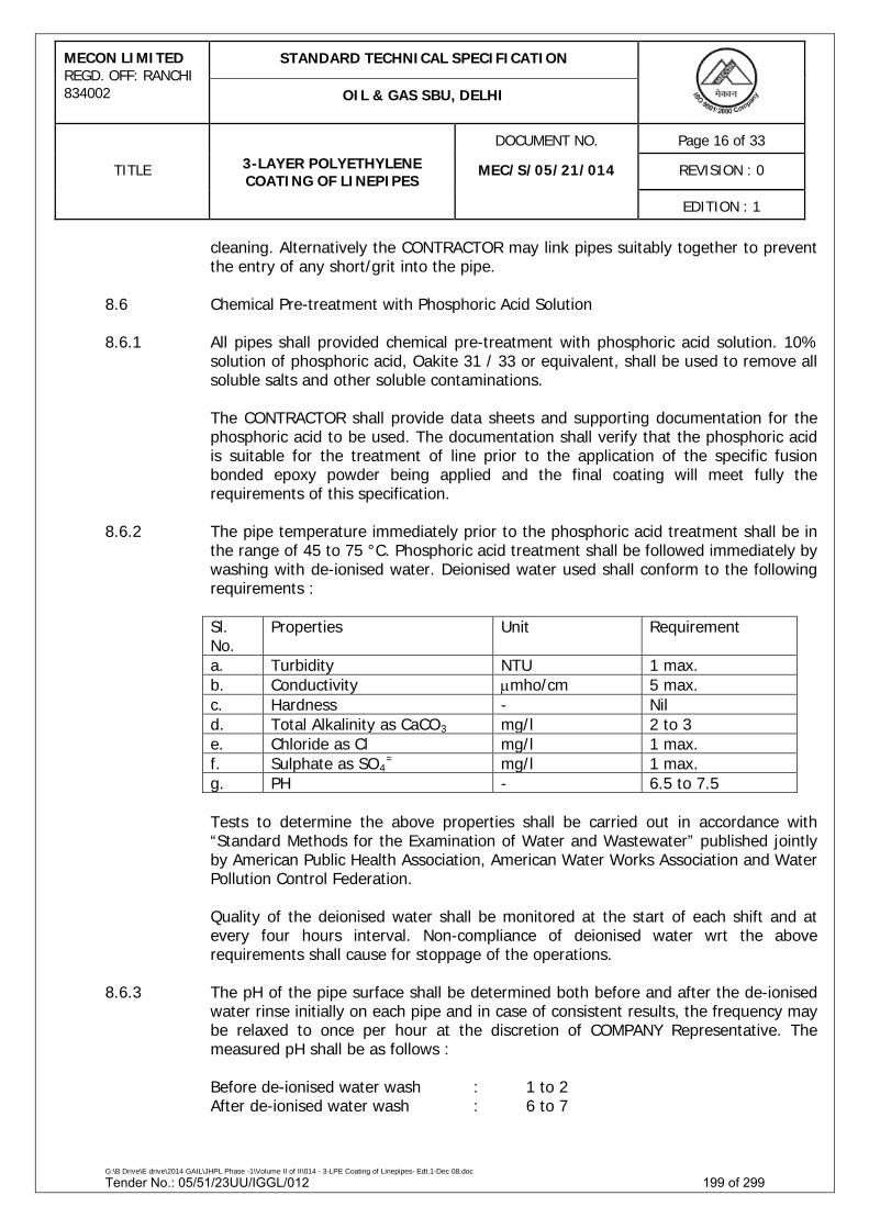
MECON LIMITED REGD. OFF: RANCHI 834002
STANDARD TECHNICAL SPECIFICATION
OIL & GAS SBU, DELHI
DOCUMENT NO. Page 16 of 33
TITLE 3-LAYER POLYETHYLENE COATING OF LINEPIPES
MEC/S/05/21/014 REVISION : 0
EDITION : 1
G:\B Drive\E drive\2014 GAIL\JHPL Phase -1\Volume II of II\014 - 3-LPE Coating of Linepipes- Edt.1-Dec 08.doc
cleaning. Alternatively the CONTRACTOR may link pipes suitably together to prevent the entry of any short/grit into the pipe.
8.6 Chemical Pre-treatment with Phosphoric Acid Solution 8.6.1 All pipes shall provided chemical pre-treatment with phosphoric acid solution. 10%
solution of phosphoric acid, Oakite 31 / 33 or equivalent, shall be used to remove all soluble salts and other soluble contaminations.
The CONTRACTOR shall provide data sheets and supporting documentation for the
phosphoric acid to be used. The documentation shall verify that the phosphoric acid is suitable for the treatment of line prior to the application of the specific fusion bonded epoxy powder being applied and the final coating will meet fully the requirements of this specification.
8.6.2 The pipe temperature immediately prior to the phosphoric acid treatment shall be in
the range of 45 to 75 °C. Phosphoric acid treatment shall be followed immediately by washing with de-ionised water. Deionised water used shall conform to the following requirements :
Sl. No.
Properties Unit Requirement
a. Turbidity NTU 1 max. b. Conductivity µmho/cm 5 max. c. Hardness - Nil d. Total Alkalinity as CaCO3 mg/l 2 to 3 e. Chloride as Cl mg/l 1 max. f. Sulphate as SO4
= mg/l 1 max. g. PH - 6.5 to 7.5
Tests to determine the above properties shall be carried out in accordance with
“Standard Methods for the Examination of Water and Wastewater” published jointly by American Public Health Association, American Water Works Association and Water Pollution Control Federation.
Quality of the deionised water shall be monitored at the start of each shift and at every four hours interval. Non-compliance of deionised water wrt the above requirements shall cause for stoppage of the operations.
8.6.3 The pH of the pipe surface shall be determined both before and after the de-ionised
water rinse initially on each pipe and in case of consistent results, the frequency may be relaxed to once per hour at the discretion of COMPANY Representative. The measured pH shall be as follows :
Before de-ionised water wash : 1 to 2 After de-ionised water wash : 6 to 7
Tender No.: 05/51/23UU/IGGL/012 199 of 299
MECON LIMITED REGD. OFF: RANCHI 834002
STANDARD TECHNICAL SPECIFICATION
OIL & GAS SBU, DELHI
DOCUMENT NO. Page 17 of 33
TITLE 3-LAYER POLYETHYLENE COATING OF LINEPIPES
MEC/S/05/21/014 REVISION : 0
EDITION : 1
G:\B Drive\E drive\2014 GAIL\JHPL Phase -1\Volume II of II\014 - 3-LPE Coating of Linepipes- Edt.1-Dec 08.doc
8.6.4 After the de-ionised water wash, the pipe shall be dried with dry air and preheated to a temperature of 65°C to 85°C.
8.6.5 The salt tests shall be carried out after de-ionised water rinse. One test shall be
carried out at one end of each pipe. The acceptance criteria shall be 2µg/cm2. An approved salt meter (SCM 400 or equivalent) shall be used to carry out salt tests and shall be calibrated in accordance with the equipment manufacturer’s recommendation.
8.7 Abrasive cleaning carried out shall be such that the resultant surface profile is not
dished and rounded when viewed with 30X magnification. The standard of finish for cleaned pipe shall conform to near white metal finish to Sa 2½ of Swedish Standard SIS 055900 latest edition. Surface of pipe after abrasive blast cleaning shall have an anchor pattern of 50 to 70 microns(Rz). This shall be measured for each pipe by a suitable instrument such as surface profile depth gauge. In addition the pipe surface after blast cleaning shall be checked for the degree of cleanliness (Sa 2½), degree of dust and shape of profile. Degree of dust shall comply the requirements of ISO:8502 – 3. Acceptance limit shall be either quality rating 2 or Class 2.
8.8 All pipes shall be visually examined for presence of any shot/ grit/ loose material left
inside the pipe during blast cleaning. Suitable mechanical means (stiff brush) shall be employed to remove the same before the pipes are processed further. In addition, inside surface of the pipe shall also be visually inspected for presence of any foreign material or shots and grit (free or embedded/ sticking to pipe inside surface). The pipe inside surface shall be examined using sharp floodlight focused at the middle of the pipe at one end while inspection is carried out visually from other end. Any foreign material or shots/ grit present in the pipe shall be completely removed by mechanical/ brush, high pressure air jets, by tilting of pipe etc.
8.9 At no time shall the blast cleaning be performed when the relative humidity exceeds
85%. The CONTRACTOR shall measure the ambient conditions at regular intervals during blast cleaning and coating operations and keep records of prevailing temperature, humidity and dew point.
8.10 The blast cleaned surface shall not be contaminated with dirt, dust, metal particles,
oil, water or any other foreign material, nor shall be surface or its anchor pattern be scarred or burnished. All blast cleaned pipe surface shall be kept in dust free enclosure prior to coating. After blast cleaning, all surfaces shall be thoroughly inspected under adequate lighting to determine anchor pattern, quality of blasting and identify any surface defects prior to coating application. All surface defects such as slivers, scab, burns, laminations, welds spatters, gouges, scores, indentations, slugs or any other defects considered injurious to the coating integrity made visible during blast cleaning shall be reported to the COMPANY Representative and on permission from COMPANY Representative, such defects shall be removed by filing or grinding. After any grinding or mechanical repairs, the remaining wall thickness shall be checked and compared with specified thickness. Ay pipes having thickness less than 95% of specified thickness shall be kept aside and disposed off as per the instructions of COMPANY Representative. The method employed to remove surface
Tender No.: 05/51/23UU/IGGL/012 200 of 299

MECON LIMITED REGD. OFF: RANCHI 834002
STANDARD TECHNICAL SPECIFICATION
OIL & GAS SBU, DELHI
DOCUMENT NO. Page 18 of 33
TITLE 3-LAYER POLYETHYLENE COATING OF LINEPIPES
MEC/S/05/21/014 REVISION : 0
EDITION : 1
G:\B Drive\E drive\2014 GAIL\JHPL Phase -1\Volume II of II\014 - 3-LPE Coating of Linepipes- Edt.1-Dec 08.doc
defects shall not burnish or destroy then anchor pattern or contaminate the surface. Pneumatic tools shall not be used unless they are fitted with effective air/ oil and water traps. Where burnishing results in destruction of anchor pattern, the anchor patter shall be restored by suitable means. Pipes which have damages repaired by grinding and have ground areas more than 50mm in diameter shall be re-blasted.
Any dust or loose residues that have been accumulated during blasting and/ or
during filing/ grinding operations shall be removed by vacuum cleaning.
If contamination of surface occurs, the quality of blast cleaning method and process shall be examined. If the surface roughness is outside the specified limit, the blast cleaning material shall be checked and replaced.
8.11 Upon Completion of the blasting operations, the quality control supervisor shall
accept the pipe for further processing or return for re-blasting after removal of defects/ imperfections. In case imperfections are considered detrimental to the coating quality, the same shall be reported to COMPANY’s Representative for final decision on rejection or re-blasting/ removal of defects. Re-blasting/ removal of defects or returning pipe to the yard shall be at the CONTRACTOR’s cost.
COMPANY’s Representative, in additions, reserves the right to initiate any of the above actions during periodic inspections for oil, dust, salt, imperfections, surface defects, lack of white metal finish etc.
8.12 In order to ensure that pipe with defects are not processed further, provisions shall
be available to lift the pipes from inspection stand. 8.13 Chemical Pre-treatment with Chromate Solution 8.13.1 Following completion of abrasive blast cleaning, all pipe surface shall be chemically
Pre-treated with a 10% strength chromate solution. 8.13.2 The CONTRACTOR shall provide data sheets and supporting documentation for the
chemical to be used. The documentation shall verify that the chemical is suitable for the treatment of line pipe prior to the application of the specific fusion bonded epoxy powder being applied and the final coating will meet fully the requirements of this specification.
8.13.3 The chemical pre-treatment shall be applied fully in accordance with the chemical
suppliers’ instructions and in a manner that ensures 100% uniform coverage of the pipe surface without introducing surface contamination.
8.13.4 The CONTRACTOR shall check that the concentration for the chemical pre-treatment
solution remains within the range recommended by the chemical manufacturer for the pipe coating process. The concentration shall be checked at the make up of each fresh solution and once per hour, using a method approved by the chemical manufacturer. The CONTRACTOR shall also ensure that the chemical pre-treatment
Tender No.: 05/51/23UU/IGGL/012 201 of 299

MECON LIMITED REGD. OFF: RANCHI 834002
STANDARD TECHNICAL SPECIFICATION
OIL & GAS SBU, DELHI
DOCUMENT NO. Page 19 of 33
TITLE 3-LAYER POLYETHYLENE COATING OF LINEPIPES
MEC/S/05/21/014 REVISION : 0
EDITION : 1
G:\B Drive\E drive\2014 GAIL\JHPL Phase -1\Volume II of II\014 - 3-LPE Coating of Linepipes- Edt.1-Dec 08.doc
solution remains free from contamination at all times. Recycling of chemical pre-treatment solution is not permitted.
8.13.5 The CONTRACTOR shall ensure that the temperature of the substrate is maintained
between 40°C and 80°C and the chromate solution temperature does not exceed 60° or as recommended by the manufacturer.
8.13.6 The chromate coating shall be smooth, even, free from runs, drips or excessive
application and lightly adherent with no flaking of the coating. The chromate coated steel must be thoroughly dried immediately after application and shall be achieved by boiling off any residual solution on the surface.
8.14 The total allowable elapsed time between completion of the blasting operations and
commencement of the pre-coating and heating operations shall be such that no detectable oxidation of the surface occurs. Relative humidity readings shall be recorded every half on hour during the blasting operations in the immediate vicinity of the operations. The maximum elapsed time shall not exceed the duration given below :
Relative Humidity % Maximum elapsed time > 80 2 hours 70 to 80 3 hours < 70 4 hours
Any pipe not processed within the above time-humidity requirement shall be
completely re-blasted. Any pipe showing flash rusting shall be re-blasted even if the above conditions have not been exceeded.
8.15 Pipe handling between abrasive blasting and pipe coating shall not damage the
surface profile achieved during blasting. Any pipe affected by the damage to the surface exceeding 200mm2 in area/ or having contamination of steel surface shall be rejected and sent for re-blasting.
9.0 COATING APPLICATION
The external surface of the cleaned pipe conforming to clause 8.0 of this specification shall be immediately coated with 3-layer extruded polyethylene coating in accordance with the procedures approved by COMPANY, relevant standards and this specification. In general, the procedure shall be as follows :
9.1 Pipe Heating 9.1.1 Immediately prior to heating of pipe, all dust and grit shall be removed from both
inside and outside of the pipe by a combination of air blast, brushing and vacuum cleaning. Suitable arrangement shall be made to protect the bevel ends from getting damaged during the coating operation.
Tender No.: 05/51/23UU/IGGL/012 202 of 299

MECON LIMITED REGD. OFF: RANCHI 834002
STANDARD TECHNICAL SPECIFICATION
OIL & GAS SBU, DELHI
DOCUMENT NO. Page 20 of 33
TITLE 3-LAYER POLYETHYLENE COATING OF LINEPIPES
MEC/S/05/21/014 REVISION : 0
EDITION : 1
G:\B Drive\E drive\2014 GAIL\JHPL Phase -1\Volume II of II\014 - 3-LPE Coating of Linepipes- Edt.1-Dec 08.doc
9.1.2 Induction heater or gas furnace shall be used for heating the pipe. The method shall be capable of maintaining uniform temperature along the total length of the pipe, and shall be such that it shall not contaminate the surface to be coated. In case of induction heating, appropriate frequency shall be used to ensure `deep heating’ and intense skin heating is avoided. Gas fired heating system shall be well adjusted so that no combustion products are deposited on the steel surface. This shall be demonstrated on bare pipes prior to start of PQT. Oxidation of the cleaned pipe surfaces prior to coating (in the form of bluing or other apparent oxide formation) is not acceptable.
9.1.3 External surface of the pipe shall be heated to about 190°C or within a temperature
range (min. to max.) as recommended by the powder manufacturer. Required pipe temperature shall be maintained as it enters the coating chamber.
9.1.4 Temperature of the pipe surface shall be continuously monitored & recorded by
using suitable instruments such as infrared sensors, contact thermometers, thermocouples etc. The recording method shall allow to correlate each line pipe. The monitoring instrument shall be able to raise an alarm/ activate audio system (hooter) in the event of tripping of induction heater/ gas fired heater or in the event of pipe temperature being outside the range recommended by the manufacturer. Any deviation from the application temperature range recommended by manufacturer shall be rectified. If immediate rectification is not feasible, the production shall be stopped until cause of deviation has been removed. Any pipe coated during the duration of temperature deviation shall be identified by marking and rejected. Such rejected pipes shall be stripped and recoated.
9.1.5 Temperature measuring & monitoring equipment shall be calibrated twice every shift
and/ or as per COMPANY representative’s instruction. 9.1.6 Contractor shall ensure that pipe surface emissivity variations are minimised during
pipe heating. To avoid significant variance, more than once blasted joints should be coated at the same time and not mixed with joints blasted only once.
9.2 Pipe Coating 9.2 .1 Subsequent to pipe heating, coating consisting of following layers shall be applied
onto the pipe.
i. Electrostatic application of epoxy powder of minimum dry film thickness 0.150 mm, unless otherwise specified. The maximum thickness shall not exceed the epoxy thickness specified by epoxy powder manufacturer.
ii. Grafted co-polymer adhesive applied by extrusion, minimum thickness 0.200 mm.
iii. Polyethylene coating by extrusion.
The coated pipe shall be subsequently quenched and cooled in water for a period which shall sufficiently lower the temperature of pipe coating to permit handling and inspection.
Tender No.: 05/51/23UU/IGGL/012 203 of 299

MECON LIMITED REGD. OFF: RANCHI 834002
STANDARD TECHNICAL SPECIFICATION
OIL & GAS SBU, DELHI
DOCUMENT NO. Page 21 of 33
TITLE 3-LAYER POLYETHYLENE COATING OF LINEPIPES
MEC/S/05/21/014 REVISION : 0
EDITION : 1
G:\B Drive\E drive\2014 GAIL\JHPL Phase -1\Volume II of II\014 - 3-LPE Coating of Linepipes- Edt.1-Dec 08.doc
9.2.2 Minimum total thickness of finished coating shall be as under :
Pipe Size (Specified Outside Diameter)
Minimum Coating Thickness (mm) (*)
Normal Type (n) Reinforced Type (v)
Up to 10¾” (273.1 mm) 2.0 2.7 Over 10¾” (273.1 mm) to below 20” (508.0 mm) 2.2 2.9
From 20” (508.0mm) to below 32” (813.0 mm) 2.5 3.2
From 32” (813.0 mm) and above 3.0 3.7
(*) In case HDPE material is used as top coat, 10% reduction in minimum
coating thickness specified is permissible. Required coating thickness shall be Normal Type (n), unless otherwise specified.
9.2.3 Coating materials shall be inspected in accordance with the manufacturer’s
recommendation prior to coating application and it shall be ensured that the materials are moisture free. In case the relative humidity exceeds 80%, the adhesive and polyethylene material shall be dried using hot air as per the directions of COMPANY representative.
9.2.4 Prior to starting the application of fusion bonded epoxy powder, the recovery system
shall be thoroughly cleaned to remove any unused powder remaining from a previous line pipe coating application. The use of recycled powder shall be permitted subjected to:
a) satisfactory qualification of the reclaimed system during PQT stage b) the proportion of the reclaimed powder in the working mix does not exceed
20% at any one time. c) the quality of the recycled powder being routinely checked during production,
at a minimum frequency of once per shift and consistently meets the requirements stated at para 5.3.1.
9.2.5 Dry air, free of oil and moisture shall be used in the coating chamber and spraying
system and for this purpose filters, dehumidifier/ heater as required alongwith control & monitoring system shall be provided for this purpose. Dew point of air used to supply the fluidized bed, epoxy spray system and epoxy recycling system shall be at least (-) 40°C and this shall be monitored during the regular production.
Tender No.: 05/51/23UU/IGGL/012 204 of 299

MECON LIMITED REGD. OFF: RANCHI 834002
STANDARD TECHNICAL SPECIFICATION
OIL & GAS SBU, DELHI
DOCUMENT NO. Page 22 of 33
TITLE 3-LAYER POLYETHYLENE COATING OF LINEPIPES
MEC/S/05/21/014 REVISION : 0
EDITION : 1
G:\B Drive\E drive\2014 GAIL\JHPL Phase -1\Volume II of II\014 - 3-LPE Coating of Linepipes- Edt.1-Dec 08.doc
9.2.6 Air pressure in the epoxy spray guns shall be controlled, continuously monitored and recorded by using suitable instruments. The air pressure shall be controlled within the limits established during coating procedure qualification. The monitoring system shall be able capable of raising an alarm/ activate audio system (hooter) in the event of change in air pressure beyond the set limits. Any deviation from the pre-set limits shall be rectified. If immediate rectification is not feasible, the production shall be stopped until cause of deviation has been removed. Any pipe coated during the duration of air pressure deviation shall be identified by suitable marking and rejected. Such rejected pipes shall be stripped and recoated.
9.2.7 Extruded adhesive layer shall be applied before gel time of the epoxy coating has
elapsed. The application of the adhesive layer shall not be permitted after epoxy is fully cured. The CONTRACTOR shall establish, to the satisfaction of the COMPANY representative, that the adhesive is applied within the gel time window of epoxy and at the temperature recommended by the adhesive manufacturer. The CONTRACTOR shall state the minimum and maximum time interval between epoxy and adhesive application at the proposed pre-heat temperature and line speed.
9.2.8 Extruded polyethylene layer shall be applied over the adhesive layer within the time
limit established during PQT stage and within the time/ temperature range recommended by the manufacturer. The extrusion temperatures of the adhesive and polyethylene shall be continuously recorded. The monitoring instruments shall be independent of the temperature control equipment. The instruments shall be calibrated prior to start of each shift.
9.2.9 CONTRACTOR shall ensure that there is no entrapment of air or void formation along
the seam weld (where applicable) during application of coating. Air entrapment below the coating and also along the coating overlap shall be prevented by forcing the coating on to the pipe using high pressure roller of suitable design during coating application. In case it is not adequately achieved, CONTRACTOR shall supplement by other method to avoid air entrapment. The methods used shall be witnessed and approved by COMPANY.
9.2.10 Resultant coating shall have a uniform gloss and appearance and shall be free from
air bubbles, wrinkles, holidays, irregularities, discontinuities, separation between layers of polyethylene & adhesive, etc.
9.2.11 Coating and/ or adhesive shall terminate 150mm (+)20/(-)0 mm from pipe ends.
The adhesive shall seal the end of applied coating. CONTRACTOR shall adopt mechanical brushing for termination of the coating at pipe ends. Edge of the coating shall be shaped to form a bevel angle of 30° to 45°.
9.2.12 Failure to comply with any of the above applicable requirement and of the approved
procedure shall be cause for the rejection of the coating and such coating shall be removed in a manner approved by COMPANY at CONTRACTOR’s expense.
Tender No.: 05/51/23UU/IGGL/012 205 of 299

MECON LIMITED REGD. OFF: RANCHI 834002
STANDARD TECHNICAL SPECIFICATION
OIL & GAS SBU, DELHI
DOCUMENT NO. Page 23 of 33
TITLE 3-LAYER POLYETHYLENE COATING OF LINEPIPES
MEC/S/05/21/014 REVISION : 0
EDITION : 1
G:\B Drive\E drive\2014 GAIL\JHPL Phase -1\Volume II of II\014 - 3-LPE Coating of Linepipes- Edt.1-Dec 08.doc
10.0 INSPECTION AND TESTING 10.1 General
CONTRACTOR shall establish and maintain such quality assurance system as are necessary to ensure that goods or services supplied comply in all respects with the requirements of this specification. The minimum inspection and testing to be performed shall be as indicated subsequently herein.
10.2 Visual Inspection
Immediately following the coated, each coated pipe shall be visually checked for imperfections and irregularities of the coating. The coating shall be of natural colour and gloss, smooth and uniform and shall be blemish free with no dust or other particulate inclusion. The coating shall not slow and defects such as blisters, pinholes, scratches, wrinkles, engravings, cuts swelling, disbonded zones, air inclusions, tears, voids or any other irregularities. Special attentions shall be paid to the areas adjacent to the longitudinal weld (if applicable), adjacent to the cut back at each of pipe and within the body of the pipe. In addition inside surface of the pipe shall also be visually inspected for presence of any foreign material or shots and grit (free or embedded/ sticking to pipe inside surface). The pipe inside surface shall be examined using sharp floodlight focussed at the middle of the pipe at line end while inspection is carried out visually form other end.
10.3 Coating Thickness
a. The coating thickness shall be determined by taking atleast 10 measurement at locations uniformly distributed over the length and periphery of each pipe. In case of weld pipes, five of the above readings shall be made at the apex of the weld seam, uniformly distributed over the length of the coated pipe. All the readings must meet the minimum requirements. However, localised coating thickness of less than the permissible minimum thickness can be tolerated on the condition that it does not attain a total extent of more than 5cm2 per meter length of coated pipe, and the actual coating thickness does not drop more than 10% below the permissible minimum coating thickness at these locations. The frequency of thickness measurement as stated above shall be initially on every pipe, which shall be further reduced depending upon consistency of results, at the sole discretion of COMPANY’s representative. Resultsof all measurement shall be recorded.
b. Thickness of epoxy and adhesive shall be measured at the beginning of each
shift and whenever the plant re-starts after any stoppage for compliance. Coating of epoxy and adhesive on portion of pipe required for this purpose, stripping and recoating of such partly coated pipe shall be at CONTRACTOR’s expense.
Tender No.: 05/51/23UU/IGGL/012 206 of 299

MECON LIMITED REGD. OFF: RANCHI 834002
STANDARD TECHNICAL SPECIFICATION
OIL & GAS SBU, DELHI
DOCUMENT NO. Page 24 of 33
TITLE 3-LAYER POLYETHYLENE COATING OF LINEPIPES
MEC/S/05/21/014 REVISION : 0
EDITION : 1
G:\B Drive\E drive\2014 GAIL\JHPL Phase -1\Volume II of II\014 - 3-LPE Coating of Linepipes- Edt.1-Dec 08.doc
c. Coated pipes not meeting the above requirements shall be rejected. The CONTRACTOR shall remove the entire coating and the pipe shall be recycled to the cleaning and coating operations as per the approved procedure and shall be to CONTRACTOR’s expenses.
10.4 Holiday Detection
a. Each coated pipe length shall be checked over 100% of coated surface by means of a “holiday detector” of a type approved by COMPANY for detecting holidays in the finished coating.
b. The holiday detector shall be a low pulse DC full circle electronic detector
with audible alarm and precise voltage control with DIN VDE 0433 Part 2. The set voltage for inspection shall be 25 kV. Travel speed shall not exceed 300 mm/s.
c. CONTRACTOR shall calibrate the holiday detector at least once every 4 hours
of production. CONTRACTOR shall have necessary instruments or devices for calibrating the holiday detector.
d. Any pipe coating shall be rejected if more than 1(one) holiday & area more
than 100 cm2 in size are detected in its length attributable to coating process.
e. Holidays which are lesser in number and size than those mentioned in (d) above, shall be repaired in accordance with a approved procedure and shall be to CONTRACTOR’s expense.
10.5 Bond Strength Test
a. CONTRACTOR shall conduct bond strength test for composite coating as per clause 5.3.3 (a) of this specification. A minimum of 65mm length shall be peeled. First 20mm and last 20mm shall not be counted for assessment of bond strength.
b. The frequency of test for cut back portions shall be one pipe in every
fifteen(15) pipes coated and for middle of pipe shall be one pipe in every sixty(60) pipes coated or one pipe per shift whichever is higher. On each selected pipe, bond strength shall be performed for each specified temperature. Test shall be performed at each cut back portion and one in the middle of pipe. The system shall disbond/ separate cohesively either in adhesive layer or in polyethylene layer. Majority of the peeled off area on the pipe shall show presence of adhesive. Disbondment/ separation at epoxy to steel interface or epoxy/ adhesive interface or adhesive/ polyethylene interface shall not be permitted. The failure mode shall be recorded for each test.
c. In case the above tests do not comply with the above requirement,
CONTRACTOR shall test all the preceding and succeeding coated pipes. If
Tender No.: 05/51/23UU/IGGL/012 207 of 299

MECON LIMITED REGD. OFF: RANCHI 834002
STANDARD TECHNICAL SPECIFICATION
OIL & GAS SBU, DELHI
DOCUMENT NO. Page 25 of 33
TITLE 3-LAYER POLYETHYLENE COATING OF LINEPIPES
MEC/S/05/21/014 REVISION : 0
EDITION : 1
G:\B Drive\E drive\2014 GAIL\JHPL Phase -1\Volume II of II\014 - 3-LPE Coating of Linepipes- Edt.1-Dec 08.doc
both pipes pass the test, then the remainder of the pipe joints in that shift shall be deemed satisfactory. If either pipe fails to meet the specified requirements, all pipes coated during the shift shall be tested until the coating is provided acceptable. Rejected coated pipes shall be stripped and re-coated in accordance with approved procedure, at CONTRACTOR’s expense.
d. The frequency of bond strength test as per para 10.5(b) for cut back portion
may be reduced depending upon the consistently of result to one pipe in every twenty five(25) instead of every fifteen pipes, at the sole discretion of the COMPANY Representative.
10.6 Impact Strength
a. Impact resistance test shall be conducted as per clause 5.3.3 (b) of this specification. Initially the frequency of test shall be 2(two) coated pipes per shift, which may be further reduced and/ or waived depending upon consistently acceptable results at the sole discretion of COMPANY’s representative.
b. Minimum thirty(30) impacts located equidistant along the length of coated
pipe shall be performed.
c. Immediately after testing, the test area shall be subjected to holiday detection at the same voltage as used prior to impact strength test. The pipe shall be rejected if any holiday is noted in the test area.
d. In case of test failure, retesting and disposal of coated pipe shall be as per
10.5(c) above. 10.7 Indentation Hardness
a. Indentation hardness test shall be as per clause 5.3.3 (c) of this specification. The frequency of test shall be initially 2(two) coated pipes per shift which shall be further reduced to one test each on 2 coated pipes per week at random after 1 week of consistently acceptable results. Two samples for each temperature shall be taken from the cut back portion of coated pipe and one in middle of the pipe for this test.
b. In case of test failure, retesting and disposal of coated pipe shall be as per
10.5(c) above. 10.8 Air Entrapment Test
a. Strips from bond strength tests or coated pipe may be used to help determine the porosity of the finished coating. Strip shall be also cut from longitudinal weld (if applicable) at cut back portion and examined for the presence of voids.
Tender No.: 05/51/23UU/IGGL/012 208 of 299

MECON LIMITED REGD. OFF: RANCHI 834002
STANDARD TECHNICAL SPECIFICATION
OIL & GAS SBU, DELHI
DOCUMENT NO. Page 26 of 33
TITLE 3-LAYER POLYETHYLENE COATING OF LINEPIPES
MEC/S/05/21/014 REVISION : 0
EDITION : 1
G:\B Drive\E drive\2014 GAIL\JHPL Phase -1\Volume II of II\014 - 3-LPE Coating of Linepipes- Edt.1-Dec 08.doc
b. Bond strength strip shall be viewed from the side and at the failure interface.
At the pipe bond strength test location, utility knife shall be used to cut the edge of the coating to a 45° angle and view with a microscope. Similar examination shall be done in the coating cut back area.
c. One sample each either on the bond strength strip or coated pipe and strip
cut from the longitudinal weld (if applicable) shall be examined for air entrapment per shift. Strips shall be viewed from the side.
d. All examination shall be done using a 30X magnification hand-held
microscope. The polyethylene and adhesive layers shall have no more than 10% of the observed area taken up with air entrapment (porosity or bubbles). Air entrapment shall not occupy more than 10% of the thickness in each case. Bubbles shall not link together to provide a moisture path to the epoxy layer.
e. In case of test failure, retesting and disposal of coated pipe shall be as per
10.5(c) above. 10.9 Degree of Cure
a. Epoxy film samples shall be removed from cut back portion of the coated pipe using hammer and cold chisel and the samples shall be taken for cure test using DSC procedure. Care shall be taken to remove the samples of full film thickness avoiding inclusion of steel debris. Glass transition temperature differential (∆Tg) and % cure (∆H) shall comply the specified requirements.
b. Frequency of this test shall be once per shift. Pipe shall be selected randomly
by COMPANY Representative during the middle of a shift. Suitable provisions/ arrangements as per the instructions of COMPANY Representative shall be made by the CONTRACTOR for this purpose.
c. In case of test failure, production carried out during the entire shift shall be
rejected, unless the CONTRACTOR proposes a method to establish the compliance with the degree of cure requirements of all pipes coated during that shift.
10.10 Epoxy Layer Adhesive Test
a. Adhesion of epoxy layer shall be determined at ambient temperature by the “St Andrews Cross” method i.e. by cutting two straight lines through the epoxy layer with a sharp knife. The incisions shall intersect at an angle of 30°/ 150°. The epoxy coating shall resist disbondment from the steel when attempts are made to flick/ lift the coating from the 30° angle with a sharp knife.
Tender No.: 05/51/23UU/IGGL/012 209 of 299

MECON LIMITED REGD. OFF: RANCHI 834002
STANDARD TECHNICAL SPECIFICATION
OIL & GAS SBU, DELHI
DOCUMENT NO. Page 27 of 33
TITLE 3-LAYER POLYETHYLENE COATING OF LINEPIPES
MEC/S/05/21/014 REVISION : 0
EDITION : 1
G:\B Drive\E drive\2014 GAIL\JHPL Phase -1\Volume II of II\014 - 3-LPE Coating of Linepipes- Edt.1-Dec 08.doc
b. Frequency of this test shall be once per shift. The test shall be carried out at the cut back portion of the pipe from which the Degree of Cure test has been carried out as per para 10.9 above.
c. In case of test failure, retesting and disposal of coated pipe shall be as per
10.9(c) above. 10.11 Cathodic Disbondment Test
a. 48 hours CD test shall be conducted as per clause 5.3.3. (h) of this specification.
b. The frequency of this test shall be once in every two weeks or one test
representing each batch of epoxy powder used, whichever is more frequent.
c. In case the test fails to conform to the specified requirement, at the option of the CONTRACTOR, all pipes coated after the previous acceptable test and prior to next acceptable test shall be rejected or the test shall be repeated or the shall be repeated using two additional samples taken from the same end of the affected pipe.
When both retests conform to the specified requirement, the lot of pipes shall be accepted. When one or both the retests fail to conform to the specified requirement, all coated pipes after previous acceptable test and prior to next acceptable shall be rejected. All rejected pipes shall be stripped, re-cleaned and re-coated. COMPANY may consider a further retest program to determine whether any of the affected pipe meet the criteria for acceptance upon written request by the CONTRACTOR.
10.12 Damages occurring to pipe coating during above tests shall be repaired in
accordance with approved coating repair procedure. 10.13 Repairs occurring on account of the production test are however excluded from
above mentioned limitations at para 10.4 (d) above.
10.14 COMPANY, reserves the right to perform inspection and witness tests on all activities concerning the pipe coating operations starting from bare pipe to finished coated pipe ready for dispatch and also testing of raw materials. CONTRACTOR shall give reasonable notice of time and shall provide without charge reasonable access and facilities required for inspection to the COMPANY’s Representative. Inspection and tests performed or witnessed by COMPANY’s Representative shall in no way relieve the CONTRACTORs obligation to perform the required inspection and tests.
10.15 In case rate of defective or rejected pipes and/ or samples tests are 10% or more for
a single shift (typically 8 hours), CONTRACTOR shall be required to stop production and carry out a full and detailed investigation and shall submit findings to COMPANY for approval. CONTRACTOR shall recommence the production only after getting the written permission from COMPANY.
Tender No.: 05/51/23UU/IGGL/012 210 of 299

MECON LIMITED REGD. OFF: RANCHI 834002
STANDARD TECHNICAL SPECIFICATION
OIL & GAS SBU, DELHI
DOCUMENT NO. Page 28 of 33
TITLE 3-LAYER POLYETHYLENE COATING OF LINEPIPES
MEC/S/05/21/014 REVISION : 0
EDITION : 1
G:\B Drive\E drive\2014 GAIL\JHPL Phase -1\Volume II of II\014 - 3-LPE Coating of Linepipes- Edt.1-Dec 08.doc
Under no circumstances any action or omission of the COMPANY’s representative shall relieve the CONTRACTOR of his responsibility for material and quality of coating produced. No pipes shall be transported from the coating plants unless authorised by COMPANY in writing.
11.0 HANDLING, TRANSPORTATION AND STORAGE 11.1 The CONTRACTOR shall be fully responsible for the pipe and for the pipe
identification marking from the time of “taking over” of bare pipe from COMPANY until such time that the coated line pipes are `handed over’ and/ or installed in the permanent installation as the case may be according to the provisions of the Contract.
At the time of “taking over” of bare pipes CONTRACTOR shall inspect and record all
the relevant details referred above including pipe defects in the presence of COMPANY. All pipes shall be checked for bevel damages, weld seam height, dents, gouges, corrosion and other damages. COMPANY Representative shall decide whether pipe defects/ damages are suitable for repair. Damage to the pipes which occur after the CONTRACTOR has taken delivery such as dents, flats, or damage to the weld ends shall be cut off or removed and pipes rebevelled and repaired again as necessary. The cost of this work, as well as that of the pipe lost in cutting and repair shall be to the CONTRACTOR’s account. All such works shall be carried out after written approval of the COMPANY. Any reduction in length shall be indicated in the CONTRACTOR’s pipe tracking system.
11.2 The CONTRACTOR shall unload, load, stockpile and transport the bare pipes within
the coating plant(s) using suitable means and in a manner to avoid damage to pipes.
The CONTRACTOR shall stockpile the bare pipes at the storage area of the coating plant. The CONTRACTOR shall prepare and furnish to COMPANY a procedure/ calculation generally in compliance with API RP-5L1 for pipe stacking, which shall be approved by COMPANY prior to commencement.
11.3 The CONTRACTOR shall load, unload, transport and stockpile the coated pipes within
the coating plant using approved suitable means and in a manner to avoid damage to the pipe and coating. The procedure shall be approved by COMPANY prior to commencement of work.
11.4 Coated pipes may be handled by means of slings and belts of proper width
(minimum 60mm) made of non-abrasive/ non-metallic materials. In this case, pipes to be stacked shall be separated row by row to avoid damages by rubbing the coated surface in the process of taking off the slings. Use of round sectional slings are prohibited. Fork lifts may be used provided that the arms of the fork lift are covered with suitable pads preferably rubber.
11.5 Bare/ coated pipes at all times shall be stacked completely clear from the ground so
that the bottom row of pipes remain free from any surface water. The pipes shall be
Tender No.: 05/51/23UU/IGGL/012 211 of 299

MECON LIMITED REGD. OFF: RANCHI 834002
STANDARD TECHNICAL SPECIFICATION
OIL & GAS SBU, DELHI
DOCUMENT NO. Page 29 of 33
TITLE 3-LAYER POLYETHYLENE COATING OF LINEPIPES
MEC/S/05/21/014 REVISION : 0
EDITION : 1
G:\B Drive\E drive\2014 GAIL\JHPL Phase -1\Volume II of II\014 - 3-LPE Coating of Linepipes- Edt.1-Dec 08.doc
stacked at a slope so that driving rain does not collect inside the pipe. Bare/ coated pipes may be stacked by placing them on ridges of sand free from stones and covered with a plastic film or on wooden supports provided with suitable cover. This cover can, for example, consist of dry, germ free straw with a plastic film, otherwise foam rubber may be used. The supports shall be spaced in such a manner as to avoid permanent bending of the pipes. Stacks shall consist of limited number of layers such that the pressure exercised by the pipe’s own weight does not cause damages to the coating. CONTRACTOR shall submit calculations for COMPANY approval in this regard. Each pipe section shall be separated by means of spacers suitably spaced for this purpose. Stacks shall be suitably secured against falling down and shall consist of pipe sections having the same diameter and wall thickness. The weld seam of pipes shall be positioned always in a manner so as not to touch the adjacent pipes. The ends of the pipes during handling and stacking shall always be protected with bevel protectors.
11.6 The lorries used for transportation shall be equipped with adequate pipe supports
having as many round hollow beds as there as pipes to be placed on the bottom of the lorry bed. Total width of the supports shall be at least 5% of the pipe length and min. 3 Nos. support shall be provided. These supports shall be lined with a rubber protection and shall be spaced in a manner as to support equal load from the pipes. The rubber protection must be free from all nails and staples where pipes are in contact. The second layer and all following layers shall be separated from the other with adequate number of separating layers of protective material such as straw in plastic covers or mineral wool strips or equivalent, to avoid direct touch between the coated pipes.
All stanchions of lorries used for transportation shall be covered by non-abrasive
material like rubber belts or equivalent. Care shall be exercised to properly cover the top of the stanchions and other positions such as reinforcement of the truck body, rivets, etc. to prevent damage to the coated surface. Slings or non-metallic straps shall be used for securing loads during transportation. They shall be suitable padded at the contact points with the pipe.
11.7 Materials other than pipes and which are susceptible of deteriorating or suffering
from damages especially due to humidity, exposure to high thermal excursions or other advers weather conditions, shall be suitably stored and protected. Deteriorated materials shall not be used and shall be replaced at CONTRACTOR’s expenses. These materials, shall always be handled during loading, unloading and storage in a manner so as to prevent any damage, alteration and dispersion. When supplied in containers and envelopes, they shall bot be dropped or thrown, or removed by means of hooks, both during the handling operations till their complete use. During unloading transport and utilization, any contact with water earth, crushed stone and any other foreign material shall be carefully avoided.
Tender No.: 05/51/23UU/IGGL/012 212 of 299

MECON LIMITED REGD. OFF: RANCHI 834002
STANDARD TECHNICAL SPECIFICATION
OIL & GAS SBU, DELHI
DOCUMENT NO. Page 30 of 33
TITLE 3-LAYER POLYETHYLENE COATING OF LINEPIPES
MEC/S/05/21/014 REVISION : 0
EDITION : 1
G:\B Drive\E drive\2014 GAIL\JHPL Phase -1\Volume II of II\014 - 3-LPE Coating of Linepipes- Edt.1-Dec 08.doc
CONTRACTOR shall strictly follow Manufacturer’s instructions regarding storage temperature and methods for volatile materials which are susceptible to change in properties and characteristics due to unsuitable storage. If necessary the CONTRACTOR shall provide for a proper conditioning.
11.8 In case of any marine transportation of bare/ coated line pipes involved, the same
shall be carried out in compliance with API RP 5LW. CONTRACTOR shall furnish all details pertaining to marine transportation including necessary drawings of cargo barges, storing/ stacking, sea fastening of pipes on the barges/ marine vessels to the COMPANY for approval prior to undertaking such transportation works. In addition CONTRACTOR shall also carry out requisite analyses considering the proposed transportation scheme and establish the same is safe and stable. On-deck overseas shipment shall not be allowed.
12.0 REPAIR OF COATING
CONTRACTOR shall submit to COMPANY, its methods and materials proposed to be used for executing a coating repair and shall receive approval from COMPANY prior to use. In open storage the repair coating materials must be able to withstand a temperature of atleast +80°C, without impairing its serviceability and properties. CONTRACTOR shall furnish manufacturer’s test certificates for the repair materials clearly establishing the compliance of the repair materials with the applicable coating requirements indicated in this specification. All pipe leaving coating plant, shall have sound external coating with no holiday porosity on 100% of the surface.
Defects, repairs and acceptability criteria shall be as follows :
• Pipes showing porosities or very small damage not picked up during holiday
test and having a surface less than 0.5 cm2 or linear damage (cut) of less than 3 cm shall be repaired by stick welding using material of same quality.
• Damages caused to coating by handling such as scratches, cuts, dents,
gouges, not picked up during holiday test, having a total reduced thickness on damaged portion not less than 2.0mm and an area not exceeding 20 cm2 shall be rebuild by heat shrink patch only and without exposing to bare metal.
• Defects or size exceeding above mentioned area or holidays of width less
than 300 mm shall be repaired with heat shrinks repair patch by exposing the bare metal surface.
• Defects exceeding the above and in number not exceeding 2 per pipe and
linear length not exceeding 500mm shall be repaired using heat shrinkable sleeves of HTLP80 or equivalent.
• Pipes with bigger damage shall be stripped and recoated.
Tender No.: 05/51/23UU/IGGL/012 213 of 299

MECON LIMITED REGD. OFF: RANCHI 834002
STANDARD TECHNICAL SPECIFICATION
OIL & GAS SBU, DELHI
DOCUMENT NO. Page 31 of 33
TITLE 3-LAYER POLYETHYLENE COATING OF LINEPIPES
MEC/S/05/21/014 REVISION : 0
EDITION : 1
G:\B Drive\E drive\2014 GAIL\JHPL Phase -1\Volume II of II\014 - 3-LPE Coating of Linepipes- Edt.1-Dec 08.doc
• In case of coating defect close to coating cut back, CONTRACTOR shall
remove the coating throughout the entire circumference of the pipe down to the steel surface and increase the coating cut back length. Now if the coating cut back exceeds 170 mm of linear length of pipe then the coating shall be repaired by the use of heat shrinkable sleeves thereby making up the coating cut back length of 150 mm.
Not withstanding the above, under no circumstances, if the defects exceeds 70mm from the original coating cut back length, the entire coating shall be removed and the pipe shall be recycled through the entire coating procedure.
Irrespective of type of repair, the maximum nos of repair of coating shall be as
follows :
• Holiday repair of size ≤ 100 cm2 attributable to process of coating application shall be maximum of one per pipe.
• In addition to the above, defects to be repaired by heat shrink patch/ sleeve shall be maximum 2(two) per pipe.
Defects exceeding the above limits shall cause pipe coating rejection, stripping and recoating. The above is exclusive of the repairs warranted due to testing as per this specification. All repairs carried out to coating for whatever reason shall be to the account of CONTRACTOR. Cosmetic damages occurring only in the Polyethylene layer only need not be repaired by exposing upto steel surface, as deemed fit by the COMPANY representative. In any case the CONTRACTOR shall establish his material, methods and procedure of repair that results in acceptable quality of product by testing and shall receive approval from COMPANY prior to use. Testing of repairs shall be in the same form as testing coating. All repairs shall result in a coating thickness no less than the parent coating thickness. CONTRACTOR shall test repairs to coating as and when required by COMPANY.
13.0 MARKING
CONTRACTOR shall place marking on the outside surface of the coating at one end of the coated pipe, and marking shall indicate, but not limited to the following information: a. Pipe number, Heat number b. Diameter & Wall Thickness c. Coated Pipe Number d. Colour band e. Any other information considered relevant by COMPANY.
Tender No.: 05/51/23UU/IGGL/012 214 of 299

MECON LIMITED REGD. OFF: RANCHI 834002
STANDARD TECHNICAL SPECIFICATION
OIL & GAS SBU, DELHI
DOCUMENT NO. Page 32 of 33
TITLE 3-LAYER POLYETHYLENE COATING OF LINEPIPES
MEC/S/05/21/014 REVISION : 0
EDITION : 1
G:\B Drive\E drive\2014 GAIL\JHPL Phase -1\Volume II of II\014 - 3-LPE Coating of Linepipes- Edt.1-Dec 08.doc
f. Pipe Manufacturer Name g. Inspection Mark/ Punch
CONTRACTOR shall obtain prior approval on making procedure to be adopted from the COMPANY.
14.0 QUALITY ASSURANCE 14.1 The CONTRACTOR shall have established within the organisation and, shall operate
for the contract, a documented Quality System that ensures that the requirements of this specification are met in all aspects. The Quality System shall be based upon ISO 9001/2 or equivalent.
14.2 The CONTRACTOR shall have established a Quality Assurance Group within its
organisation that shall be responsible for reviewing the Quality System and ensuring that it is implemented.
14.3 The CONTRACTOR shall submit the procedures that comprise the Quality System to
the COMPANY for agreement. 14.4 The CONTRACTOR’s Quality System shall pay particular attention to the control of
Suppliers and sub-contractors and shall ensure that the requirements of this specification are satisfied by the Suppliers and Sub-contractors operating Quality system in their organisation.
14.5 The CONTRACTOR shall, prior to the commencement of work, prepare and issue a
Quality plan for all of the activities required to satisfy the requirements of this specification. The plan shall include any sub-contracted work, for which the sub-contractors Quality plans shall be submitted. The plan shall be sufficiently detailed to indicate sequentially for each discipline the requisite quality control, inspection , testing and certification activities with reference to the relevant procedures and the acceptance standards.
14.6 The CONTRACTOR’s Quality system and associated procedures may, with due notice,
be subject to formal audits. The application of quality control by the CONTRACTOR will be monitored by the COMPANY Representatives who will witness and accept the inspection testing and associated work required by this specification.
Tender No.: 05/51/23UU/IGGL/012 215 of 299

MECON LIMITED REGD. OFF: RANCHI 834002
STANDARD TECHNICAL SPECIFICATION
OIL & GAS SBU, DELHI
DOCUMENT NO. Page 33 of 33
TITLE 3-LAYER POLYETHYLENE COATING OF LINEPIPES
MEC/S/05/21/014 REVISION : 0
EDITION : 1
G:\B Drive\E drive\2014 GAIL\JHPL Phase -1\Volume II of II\014 - 3-LPE Coating of Linepipes- Edt.1-Dec 08.doc
ANNEXURE-I
LIST OF ACCEPTABLE COMBINATIONS OF COATING MATERIALS
The following combinations of coating materials are considered acceptable. In the event of award of contract, CONTRACTOR shall furnish the combination(s) proposed and reconfirmation of compatibility & properties of the proposed combination (s) from the raw materials Manufacturers & system properties.
Epoxy Powder (Manufacturer)
Adhesive (Manufacturer)
PE Compound (Manufacturer)
CORRO-COAT EP-F 2001 (JOTUN)
FUSABOND 158D (DUPONT)
SCLAIR 35 BP HDPE (NOVACOR)
PE 50-8190/8191 LUCALEN G3510H LUPOLEN 3652 D SW 00413 (BASF) (BASF) (BASF)
or CORRO-COAT EP-F 2001
(JOTUN)
PE 50-6109 ME 0420 HE 3450 (BASF) (BOREALIS) (BOREALIS)
or CORRO-COAT EP-F
2001/2002HW (JOTUN) or
SCOTCHKOTE 226N (3M)
CORRO-COAT EP-F 2001 LE – 149 V ET 509 B (JOTUN) (S K CORPORATION) (S K CORPORATION)
SCOTCHKOTE 226N ME 0420 PB 48A004 (3M) (BOREALIS) (GAIL)
Although the above combinations would be acceptable to COMPANY, the responsibility of suitability for application, performance, properties and compliance to the coating system requirements shall unconditionally lie with the CONTRACTOR.
Tender No.: 05/51/23UU/IGGL/012 216 of 299

SPECIFICATION
FOR INTERNAL EPOXY COATING FOR LINE PIPES
SPECIFICATION NO.: MEC/TS/05/21/014B
(OIL & GAS SBU) MECON LIMITED DELHI 110 092
Rev. : 0 Edition : 1
Tender No.: 05/51/23UU/IGGL/012 217 of 299

MECON LIMITED REGD. OFF: RANCHI 834002
STANDARD TECHNICAL SPECIFICATION
OIL & GAS SBU, DELHI
DOCUMENT NO. Page 1 of 1
TITLE INTERNAL EPOXY COATING FOR LINE PIPES
MEC/TS/05/21/014B REVISION : 0
EDITION : 1
C O N T E N T S
1 SCOPE 2 DEFINITIONS 3 ABBREVIATIONS 4 INTERNAL LIQUID EPOXY COATING 5 COATING MATERIAL 6 APPLICATION OF THE COATING MATERIAL 7 PRODUCTION CONTROL 8 REPAIRS 9 HANDLING, TRANSPORTATION AND STORAGE ANNEX A : (NORMATIVE) DETERMINATION OF ASH (REFER TO SUB CLAUSE 5.2.5) ANNEX B : (NORMATIVE) DRY FILM THICKNESS (REFER TO SUB CLAUSE 5.3.3 AND 7.1.2) ANNEX C : (NORMATIVE) RESISTANCE TO GAS PRESSURE VARIATION (REFER TO SUB CLAUSE 5.3.9) ANNEX D : (NORMATIVE) HYDRAULIC- PRESSURE BLISTERING (REFER TO SUB CLAUSE 5.3.12) ANNEX E : (NORMATIVE) POROSITY OF A FILM OF THE COATING MATERIAL ON A GLASS PANEL (REFER TO SUB CLAUSE 7.2.6) ANNEX F : (NORMATIVE) CURING TEST (REFER TO SUB CLAUSE 7.2.5) ANNEX G : (NORMATIVE) WET-SPONGE TEST (REFER TO SUB CLAUSE 7.2.6) PREPARED BY:
(Sachin Singhal)
CHECKED BY:
(A.K. Gupta)
APPROVED BY:
(A.K. Johri)
ISSUE DATE :
Aug. 2008
Tender No.: 05/51/23UU/IGGL/012 218 of 299

MECON LIMITED REGD. OFF: RANCHI 834002
STANDARD TECHNICAL SPECIFICATION
OIL & GAS SBU, DELHI
DOCUMENT NO. Page 1 of 1
TITLE INTERNAL EPOXY COATING FOR LINE PIPES
MEC/TS/05/21/014B REVISION : 0
EDITION : 1
AMENDMENT STATUS
Sl. No.
Clause / Paragraph / Annexure / Exhibit / Drawing Amended
Page No.
Revision Date By (Name)
Verified (Name)
Tender No.: 05/51/23UU/IGGL/012 219 of 299

MECON LIMITED REGD. OFF: RANCHI 834002
STANDARD TECHNICAL SPECIFICATION
OIL & GAS SBU, DELHI
DOCUMENT NO. Page 1 of 26
TITLE INTERNAL EPOXY COATING FOR LINE PIPES
MEC/TS/05/21/014B REVISION : 0
EDITION : 1
1 SCOPE
The intent of this specification is to set forth the minimum requirements for supply / arrangement of all materials, plant, equipments, plant sites consumables, utilities and application including all labour, supervision, inspection & test etc for application of internal epoxy coating.
2 DEFINITIONS
The COATING CONTRACTOR is the party, who will do coating, supplies equipment and services to perform the duties specified by the contractor. CONTRACTOR / VENDOR means the person(s) named as contractor in the FORM OF AGREEMENT and the legal successors in title to this person (s). The word shall indicates a requirement The word should indicates a recommendation
3 ABBREVIATIONS
ASTM - American Society for Testing and Materials BS - British Standards DIN - Deutsche Industries Normen FBE - Fusion Bonded Epoxy ISO - International Organisation of Standardisation NACE - National Association of Corrosion Engineers SSPC - Steel Structures Painting Council
3.1 Codes, Regulations and Standards
The latest edition of the following codes and standards shall establish the minimum standards for the work. VENDOR may use alternate standards that meet or exceed those if approved by OWNER. American Society for Testing and Materials (ASTM) - ASTM D 638 Test Methods for Tensile Properties of Plastics - ASTM G95 Test Method for Cathodic Disbonding of Pipeline Coatings. International Standards Organization (ISO) - ISO 9002 Quality System – Quality Assurance in Production, Installation and
Servicing
Tender No.: 05/51/23UU/IGGL/012 220 of 299

MECON LIMITED REGD. OFF: RANCHI 834002
STANDARD TECHNICAL SPECIFICATION
OIL & GAS SBU, DELHI
DOCUMENT NO. Page 2 of 26
TITLE INTERNAL EPOXY COATING FOR LINE PIPES
MEC/TS/05/21/014B REVISION : 0
EDITION : 1
- ISO 8501-1 Preparation of Steel Substrates before Application of (Part I) Paints and Related Products – Visual Assessment of Surface Cleanliness
- ISO 8503-1 Preparation of Steel Substrates before Application of (Part 1) Paints and
Related Products – Visual Assessment of Surface Cleanliness - ISO 15741 Paints and Varnishes – Friction-reduction coatings for the interior of on
– and offshore steel pipeline for non-corrosive gases. British Standards (BS) - BS 5750 Specification for Final Inspection and Testing (Part 3) Deutsche Institute Fur Normung (DIN) - DIN 30670 Polyethylene Coatings for Steel Pipes and Fittings - DIN 50049 Inspection Documents for the Delivery of Metallic Products.
3.4 Document Precedence
The VENDOR shall notify OWNER / CONSULTANT of any conflict between this specification, the related data sheets, the Codes and Standards and any other specifications noted herein. Resolution and / or interpretation precedence shall be obtained from OWNER / CONSULTANT in writing before proceeding with the design & manufacture. In case of conflict, the order of precedence shall be: • Coating Data Sheets • Coating Narrative Specification • Design General Specification and Standards • Industry Codes and Standards
4 INTERNAL LIQUID EPOXY COATING
Each pipeline shall be provided with an internal liquid epoxy coating by the Vendor. The internal coating shall be as per ISO 15741 – 2001 (E).
5 COATING MATERIAL 5.1 General
The coating material shall typically be a two-pack epoxy paint. It shall not contain any substances which will be released from the paint film after it has cured and are proven to be detrimental to the operation of the pipeline and the quality of the gas. Unless otherwise agreed, the coating material shall be qualified in accordance with 5.2 and 5.3 and shall not be changed after qualification.
Tender No.: 05/51/23UU/IGGL/012 221 of 299

MECON LIMITED REGD. OFF: RANCHI 834002
STANDARD TECHNICAL SPECIFICATION
OIL & GAS SBU, DELHI
DOCUMENT NO. Page 3 of 26
TITLE INTERNAL EPOXY COATING FOR LINE PIPES
MEC/TS/05/21/014B REVISION : 0
EDITION : 1
The manufacturer of the coating material shall provide on request infrared spectrograms of the base component and the curing agent component (see 5.2.8) In addition, the manufacturer shall provide a product data sheet (see 5.6), a health and safety data sheet and a certificate stating the test results obtained in accordance with 5.2 and 5.3 respectively and, if applicable, deviating test conditions. The manufacturer shall also provide with every batch of the coating material a batch test certificate stating the information as given in 5.8. Unless otherwise agreed, the applied coating shall provide corrosion protection during storage and transport for a minimum period of one year without significant breakdown of the coating. The typical operating-temperature range for this type of coating is between -20 °C and 110°C. Where, subsequently, external coatings have to be applied, care shall be taken not to allow the internal coating to be damaged by the elevated temperatures which may occur.
5.2 Particular requirement for qualification of the coating material 5.2.1 General
The following sub clauses describe the laboratory test methods which are required for qualification of the coating material.
5.2.2 Non-volatile matter (by mass)
When determined in accordance with ISO 3251, the non-volatile matter (by mass) of the coating material shall comply with the value specified by the coating material manufacturer in the qualification certificate (Table 2)
5.2.3 Non-volatile matter (by volume)
When determined in accordance with ISO 3233, the non-volatile matter (by volume) of the coating material shall comply with the value specified by the coating material manufacturer in the product data sheet (Table 1)
5.2.4 Viscosity
When determined by the method specified by the manufacturer, the viscosity of the ready-mixed coating material shall comply with the value specified by the coating material manufacturer in the qualification certificate (Table 2) The viscosity should preferably be measured with ISO 2431
Tender No.: 05/51/23UU/IGGL/012 222 of 299

MECON LIMITED REGD. OFF: RANCHI 834002
STANDARD TECHNICAL SPECIFICATION
OIL & GAS SBU, DELHI
DOCUMENT NO. Page 4 of 26
TITLE INTERNAL EPOXY COATING FOR LINE PIPES
MEC/TS/05/21/014B REVISION : 0
EDITION : 1
5.2.5 Density When determined in accordance with one of the parts of ISO 2811, the density of the coating material shall comply with the value specified by the coating material manufacturer in the product data sheet (Table 1)
5.2.6 Ash (residue on ignition)
When determined in accordance with the method described in annex A, the ash (residue on ignition) of the coating material shall comply with the value specified by the coating material manufacturer in the qualification certificates (Table 2)
5.2.7 Pot life
The pot life is considered to be the time taken by the ready-mixed coating material to reach a condition at which it can no longer be applied satisfactorily. The pot life shall be specified in the product data sheet (see 5.6)
5.2.8 Infrared spectrograms
Infrared spectrograms of the base component and the curing agent component shall be submitted on request.
5.2.9 Appearance
The appearance and continuity of the coating shall be inspected visually without any magnification.
5.3 Particular requirement for qualifications of the cured paint film 5.3.1 Preparation of test panels
Perform the tests specified in 5.3.3 to 5.3.12 on coatings applied to the required dry film thickness specified in 5.3.3 by spraying on to test panels (steel or glass). Prepare steel test panels as specified in 6.2 and glass panels as specified each test at least in duplicate.
5.3.2 Conditions of test panels
If specified, condition the coated test panels using one of the following cycles, depending on the substrate and on the individuals test. Cycle B and cycle C are optional and the choice of the conditioning cycle depends on the time available to perform the test procedure.
Cycle A Substrate: Steel or Glass - Condition at 18 0C to 25 0C and ≤ 80% relative humidity until the coating is at least
tack-free.
Tender No.: 05/51/23UU/IGGL/012 223 of 299

MECON LIMITED REGD. OFF: RANCHI 834002
STANDARD TECHNICAL SPECIFICATION
OIL & GAS SBU, DELHI
DOCUMENT NO. Page 5 of 26
TITLE INTERNAL EPOXY COATING FOR LINE PIPES
MEC/TS/05/21/014B REVISION : 0
EDITION : 1
- Dry for 30 minutes in a circulating-air oven at (75±2) 0C - Condition for a minimum of 30 minutes at 18 0C to 25 0C and ≤ 80% relative
humidity before testing. Cycle B Substrate: Steel or Glass - Condition at 18 0C to 25 0C and ≤ 80% relative humidity until the coating is at least
tack-free. - Dry for 30 minutes in a circulating-air oven at (150±2) 0C - Condition for a minimum of 30 minutes at 18 0C to 25 0C and ≤ 80% relative
humidity before testing. Cycle C Substrate: Steel or Glass - Condition at 18 0C to 25 0C and ≤ 80% relative humidity until the coating is at least
tack-free. - Dry for 30 minutes in a circulating-air oven at (40±2) 0C - Condition for a minimum of 30 minutes at 18 0C to 25 0C and ≤ 80% relative
humidity before testing. 5.3.3 Dry film thickness
Unless otherwise agreed, the dry film thickness of the coating, applied on a glass or steel panel, shall be minimum 80 µm except for the test described in 5.3.6 (resistance to neutral salt spray). Unless otherwise agreed, the dry film thickness shall be measured in accordance with ISO 2808: 1997, Method No. 2 for glass and Method No. 10 for blast-cleaned steel, following the procedure given in annex B.
5.3.4 Adhesion
When determined in accordance with ISO 2409, the cross-cut classification of the coating applied on steel panels and conditioned using cycle B or C (see 5.3.2) shall be equal to or lower than 1.
Tender No.: 05/51/23UU/IGGL/012 224 of 299

MECON LIMITED REGD. OFF: RANCHI 834002
STANDARD TECHNICAL SPECIFICATION
OIL & GAS SBU, DELHI
DOCUMENT NO. Page 6 of 26
TITLE INTERNAL EPOXY COATING FOR LINE PIPES
MEC/TS/05/21/014B REVISION : 0
EDITION : 1
5.3.5 Buchholz hardness
When determined in accordance with ISO 2815, the Buchholz hardness of the coating, applied on glass or steel panels and conditioned using cycle B or C (see 5.3.2) shall have a value of 94 or more.
5.3.6 Resistance to neutral salt spray
The coating, applied on steel panels with a dry film thickness of 60 Gm to 75 Gm, conditioned using cycle B or C (see 5.3.2), and with an X-cut down to the substrate at least 20 mm from any edge, shall be tested in accordance with ISO 7253 for 480 h. After the test, allow the test panels to dry for at least 30 min at 18 0C to 25 0C and ≤ 80% relative humidity. The coating shall be free from any signs of deterioration, for example blistering (except in the area within 2.0 mm from the X-cut), cracking and staining. Any corrosion shall extend not more than 2.0 mm at the most from the X-cut. It shall not be possible to remove by means of clear plastic tape more than 3.0 mm of the coating in any direction from the area around the X-cut.
5.3.7 Resistance to artificial ageing
Prepare two different sets of coated test panels, each set consisting of 3 steel panels. The dimensions of the panels shall be approx. 100 mm X 50 mm X 0.8 mm. Carry out the following procedure: - Condition set 1 using cycle C (see 5.3.2) - Condition set 2 using cycle C (see 5.3.2) and then age the panel 80 0C in a
circulating-air oven for 100 h followed by conditioning for 24 h at 18 0C to 25 0C and ≤ 80% relative humidity.
- After ageing, subject the test panels to a bend test in accordance with 5.3.8 The result of the bend test shall comply with the requirement specified in 5.3.8.
5.3.8 Bend test (conical mandrel)
Prepare steel panels and condition them using cycle B or C (see 5.3.2). When the panel are tested in accordance with ISO 6860, the maximum extent of cracking along the panel from the small and of the mandrel shall be less than or equal to 13 mm, and there shall be no loss of adhesion.
5.3.9 Resistance to gas pressure variations
Prepare steel panels and condition them using cycle B or C (see 5.3.2). When the panels are tested with annex C, they shall have a generally good appearance when examined in accordance with 5.2.9 and shall not show any blistering. The adhesion value shall fulfil the
Tender No.: 05/51/23UU/IGGL/012 225 of 299

MECON LIMITED REGD. OFF: RANCHI 834002
STANDARD TECHNICAL SPECIFICATION
OIL & GAS SBU, DELHI
DOCUMENT NO. Page 7 of 26
TITLE INTERNAL EPOXY COATING FOR LINE PIPES
MEC/TS/05/21/014B REVISION : 0
EDITION : 1
requirements are given in 5.3.4 after conditioning for 24 h and 40 h at 18 0C to 25 0C and ≤ 80% relative humidity.
5.3.10 Resistance to water immersion
Prepare steel panels and conditions them using cycle B or C (see 5.3.2). When the panels are tested in accordance with ISO 2812 – 2 for 480 h, the coating shall not show any blistering or appreciable softening.
The examination shall be carried out 3 min after the panels have been removed from the test liquid.
5.3.11 Resistance to chemicals
Prepare steel panels and condition then using cycle B or C (see 5.3.2). When the panels are tested in accordance with ISO 2812-1:1993, Method No. 1, Procedure a, for 168 h, the coating shall not show any blistering or appreciable softening. Use the following test liquid: cyclo hexane; 95% by volume di-ethylene glycol solution in water; hexane; methanol; toluene and lubricating oil (e.g. compressor shall oil in accordance with ISO 6743-4). The test panels shall be completely immersed in the test liquid. The examination shall be carried out at 18 0C to 25 0C and ≤ 80% relative humidity 3 min after the panels have been removed from the test liquid. After conditioning for 24 h at 18 0C to 25 0C and ≤ 80% relative humidity, the adhesion value shall fulfil the requirements given in 4.3.4. A change in the colour of the coating shall not be considered as an indication of inferior coating quality.
5.3.12 Resistance to hydraulic blistering
Prepare steel panels and condition them using cycle B or C (see 5.3.2). When the panels are tested in accordance with annex D, the coating shall not show any blistering. The examination shall be carried out at 18 0C to 25 0C and ≤ 80% relative humidity 3 min after the panels have been removed from the test liquid. The adhesion value shall fulfil the requirements given in 5.3.4 after conditioning at 18 0C to 25 0C and ≤ 80% relative humidity for 24 h.
5.4 Packaging, labelling and storing
All coating materials and solvents shall be stored in the original container bearing the manufacturer’s label and instruction. At least the following information shall be shown on the label: - The name of the coating material; - The name of the manufacturer of the coating material; - The colour of the coating material; - The batch number; - Instructions and warnings regarding health, safety and environmental protection;
Tender No.: 05/51/23UU/IGGL/012 226 of 299

MECON LIMITED REGD. OFF: RANCHI 834002
STANDARD TECHNICAL SPECIFICATION
OIL & GAS SBU, DELHI
DOCUMENT NO. Page 8 of 26
TITLE INTERNAL EPOXY COATING FOR LINE PIPES
MEC/TS/05/21/014B REVISION : 0
EDITION : 1
- a reference to the relevant product data sheet; 5.5 Quality Assurance
It necessary to ensure that the goods or services supplied comply in all respects with the requirements of this International Standard. The coater shall therefore set up and maintain a quality assurance system as, for example, detailed in ISO 9001.
The purchaser shall have the right to undertake inspection and testing of the coated goods during any stage of coating at which the quality of the finished goods may be affected and to undertake inspection or testing of coating materials, or other materials used, to ensure compliance with the requirement given in 5.2 and 5.3.
5.6 Product data sheet
The coating material manufacturer’s product data sheet give information regarding at least the items listed in Table 1.
Table 1 – Minimum information to be included in product data sheet
Date of issue Name of coating material Name of coating material manufacturer Colour of coating material Type of coating material Shelf life Non-volatile matter by volume a Test method used (see5.3.2) Density b Test method used (see 5.2.5) Pot life a (see 5.2.7) Flash point c Time to complete curing Recommended thinner Maximum allowed quantity of thinner, in % Recommended surface preparation grade Recommended method of application Recommended maximum / minimum dry film thickness of the applied coating Recommended cleaning solvent (for the application equivalent) Recommended application conditions (air and steel temperature and relative humidity)
Tender No.: 05/51/23UU/IGGL/012 227 of 299

MECON LIMITED REGD. OFF: RANCHI 834002
STANDARD TECHNICAL SPECIFICATION
OIL & GAS SBU, DELHI
DOCUMENT NO. Page 9 of 26
TITLE INTERNAL EPOXY COATING FOR LINE PIPES
MEC/TS/05/21/014B REVISION : 0
EDITION : 1
Recommended minimum curing conditions Recommended maximum / minimum service temperature Recommended storage conditions Reference to instruction and warnings regarding health, safety and environmental protection Theoretical spreading rate (l/m2 or kg/m2) for a given dry film thickness. a. Only for the mixed coating material. b. Give separately for base component and curing agent component (if pigmented) c. Give separately for base component, curing agent component and mixed coating material. 5.7 Qualification certificate
The qualification certificate shall give, as a minimum, the values of the properties listed in Table 2.
Table 2 – Minimum information to be included in qualification certificate
Date of issue Name of coating material Mane of coating material manufacturer Authority of issue
Property Test Method Sub Clause Non-volatile matter by mass a ISO 3251 See 5.2.2 Ash b Annex A See 5.2.6 Viscosity c See 5.2.4 Adhesion ISO 2409 See 5.3.4 Buchholz hardness ISO 2815 See 5.3.5 Resistance to neutral salt spray ISO 7253 See 5.3.6 Resistance to artificial ageing See 5.3.7 Bend test (conical mandrel) ISO 6860 See 5.3.8 Resistance to gas pressure variations Annex C See 5.3.9 Resistance to water immersion ISO 2812-2 See 5.3.10 Resistance to chemicals - Resistance to cyclohexane - Resistance to 95% by volume diethylene glycol solution in water
Tender No.: 05/51/23UU/IGGL/012 228 of 299

MECON LIMITED REGD. OFF: RANCHI 834002
STANDARD TECHNICAL SPECIFICATION
OIL & GAS SBU, DELHI
DOCUMENT NO. Page 10 of 26
TITLE INTERNAL EPOXY COATING FOR LINE PIPES
MEC/TS/05/21/014B REVISION : 0
EDITION : 1
- Resistance to hexane ISO 2812-1 See 5.3.11 - Resistance to methanol - Resistance to toluene - Resistance to lubricating oil (e.g. compressed seal oil) Resistance to hydraulic blistering Annex D See 5.3.12 a. Separate for base component, curing agent component and mixed coating material. b. Separate for base component and curing agent component (if pigmented). c. Only for the mixed coating material. 5.8 Batch test certificate
The batch test certificate shall give, as a minimum, the information and test results for the items listed in Table 3
Table 3 – Minimum information to be included in batch test certificate
Item Test
Method Information from the
Coating Material Manufacturer
Test Results
Date of issue Batch number Name of coating material Name of coating material manufacturer
Production date Expiry date for use Non-volatile matter by mass – base component
See 5.2.2
Non-volatile matter by mass – curing agent component a
See 5.2.2
Viscosity – base component b Viscosity – curing agent component
b
Density – base component See 5.2.5 Density – curing agent component See 5.2.5
Tender No.: 05/51/23UU/IGGL/012 229 of 299

MECON LIMITED REGD. OFF: RANCHI 834002
STANDARD TECHNICAL SPECIFICATION
OIL & GAS SBU, DELHI
DOCUMENT NO. Page 11 of 26
TITLE INTERNAL EPOXY COATING FOR LINE PIPES
MEC/TS/05/21/014B REVISION : 0
EDITION : 1
Item Test Method
Information from the Coating Material
Manufacturer
Test Results
Ash – base component c See 5.2.6 Ash – curing agent component c, d See 5.2.6 Infrared spectrogram d, e See 5.2.8 a. The non-volatile matter by mass of the curing agent component shall not be used for any
purposes other than batch consistency checks. b. As specified by the coating material manufacturer. c. If required. d. If pigmented. e. Separately for base component and curing agent component. 6 APPLICATION OF THE COATING MATERIAL 6.1 General
During application of the coating material, all steps in the coating process shall be assessed and recorded.
The parameters listed in Table 4 shall be included.
Table 4 – Minimum items to be checked and recorded during the coating process
Items Method Frequency Acceptance
criteria Coating material Name of product Name of manufacturer Batch number
Visual examination
At every change of shift At every change of shift At every change of shift
As specified As specified As specified
Surface condition prior to surface preparation
Visual examination
Every pipe As specified
Surface condition after surface preparation Surface cleanliness Surface profile
ISO 8501-1 ISO 8503-2
Twice per shift Twice per shift
As specified As specified
Surface imperfections E.g. dents, laps
Visual examination
Every pipe Subject to agreement
Wet paint (mixed) Viscosity and temperature
As specified Every time paint is mixed and every time painting
is interrupted
As specified
Environmental conditions in the painting area
Instrumental Instrumental
At every change of shift At every change of shift
As specified As specified
Tender No.: 05/51/23UU/IGGL/012 230 of 299

MECON LIMITED REGD. OFF: RANCHI 834002
STANDARD TECHNICAL SPECIFICATION
OIL & GAS SBU, DELHI
DOCUMENT NO. Page 12 of 26
TITLE INTERNAL EPOXY COATING FOR LINE PIPES
MEC/TS/05/21/014B REVISION : 0
EDITION : 1
Items Method Frequency Acceptance criteria
Ambient temperature Steel temperature Relative humidity Flash point
Instrumental Instrumental
At every change of shift At every change of shift
As specified As specified
Cured paint film on pipes Appearance and continuity Dry film thickness Porosity (pinholes)
Visual examination
ISO 2808:1997, Method 10 Wet-sponge
test (annex G)
Spot test Twice per shift a
No sagging As specified As
required
Cured paint film on steel test panels As described in Table 5
See table 5 Twice per shift As specified in Table 5
Paint film on glass test panels Porosity (pinholes)
Annex E At every change of shift Max. 5 pores
a. The wet sponge test shall be carried out only if the porosity test on glass panels constitutes a failure
6.2 Surface preparation
First check that the surface are free from any foreign matter such as welding flux, welding spatter, salts, oil or grease. If necessary, wash the surfaces with a high-pressure jet of fresh water. Removed organic contaminants using detergents or suitable organic solvents. Then blast-clean the surfaces to surface preparation grade Sa 2 ½ in accordance with ISO8501-1. Removed, using suitable methods, any surface irregularities or imperfections which may have become visible. Check the surface profile. Unless otherwise agreed, it shall be such that R γ5 (see ISO 8503-1) is between 25 µm and 60 µm. During and after blast-cleaning and prior to application of the coating material, the temperature of the steel surface shall be at least 3 0C above the dew point or the minimum curing temperature given by the coating material manufacturer, whichever is the higher.
6.3 Paint preparation
Before removing each component from its container, stir or agitate it until it is homogeneous, using equipment which is capable of homogenizing the entire contents of the container without excessively entraining air into the material. Mix the two components (base
Tender No.: 05/51/23UU/IGGL/012 231 of 299

MECON LIMITED REGD. OFF: RANCHI 834002
STANDARD TECHNICAL SPECIFICATION
OIL & GAS SBU, DELHI
DOCUMENT NO. Page 13 of 26
TITLE INTERNAL EPOXY COATING FOR LINE PIPES
MEC/TS/05/21/014B REVISION : 0
EDITION : 1
component and curing agent component) thoroughly and, if necessary, dilute in accordance with the coating material manufacturer’s instructions. After the material has been homogenized, it shall be continuously mixed at a slow speed. The mixed paint shall be free of any lumps and pieces of skin. Measure the viscosity in accordance with the method recommended by the manufacturer and record it. Check whether it complies with the value specified by the manufacturer and keep it constant during application procedure.
6.4 Paint application
Check the surface to be coated to see whether it still complies with the specified surface preparation grade and profile (see 6.2).
Apply the paint in a covered or enclosed space, shielded from wind, blowing dust and inclement weather, using the application parameters recommended bt the coating material manufacturer and approved by the coater. The ambient temperature and relative humidity and the temperature of the steel surface application and subsequent drying/ curing shall be in accordance with the recommendations of the manufacturer of the coating material. The temperature of the steel shall be at least 3 0C above the dew point. In the case of accelerated curing, the temperature shall be as agreed between the coating material manufacturer and the coater. Spray the paint continuously and uniformly on to the whole surface to be coated. The coating shall be uniform, and particular attention shall be given to achieving the specified dry film thickness. Unless otherwise specified or agreed, maintain a cutback length of (20 ± 5) mm.
6.5 Health and safety and protection of the environment It is the duty of clients, specifiers, contractors, coating material manufacturers, inspectors and all other personnel involved in the undertaking to carry out the work for which they are responsible in such a manner that they do not endanger the health and safety of themselves or others. In pursuance of this duty, each person shall ensure that all the statutory requirement of the country in which their work, or any part of the work, is carried out are complied with.
7 PRODUCTION CONTROL 7.1 Assessment of the coating on the pipes 7.1.1 Appearance
Inspect the coating visually for uniformity of colour, smoothness and freedom from runs, holidays and other defects that could be detrimental to its quality.
Tender No.: 05/51/23UU/IGGL/012 232 of 299

MECON LIMITED REGD. OFF: RANCHI 834002
STANDARD TECHNICAL SPECIFICATION
OIL & GAS SBU, DELHI
DOCUMENT NO. Page 14 of 26
TITLE INTERNAL EPOXY COATING FOR LINE PIPES
MEC/TS/05/21/014B REVISION : 0
EDITION : 1
7.1.2 Dry film thickness Unless otherwise specified or agreed, the minimum dry film thickness of the coating shall be 80 µm above the peaks in the profile of the substrate and shall be determined in accordance with annex B.
7.2 Assessment of the coating on steel panels 7.2.1 Preparation of test panels
Perform the tests specified in 7.2.2 to 7.2.5 on coating applied by spraying on to steel test panels, to give dry film thickness specified in 5.3.3. Prepare the test panels as specified in 6.2 and apply the paint in accordance with the instructions of the coating material manufacturer. Use conditioning cycle B or C (see 5.3.2). Perform each test at least in duplicate. Table 5 shows the required frequency of the tests specified in 7.2.2 to 7.2.5
7.2.2 Adhesion
When determined in accordance with ISO 2409, the cross-cut classification of the coating shall be equal to or lower than 1.
7.2.3 Buchholz hardness
When determined in accordance with ISO 2815, the Buchholz hardness of the coating shall be at least 94.
7.2.4 Bend test
When determined in accordance with ISO 6860, the maximum extent of cracking along the panel from the small end of the mandrel shall be less than or equal to 13 mm, and there shall be no loss adhesion.
7.2.5 Curing test
When tested in accordance with annex F, the coating shall not show any softening, wrinkling or blistering.
7.2.6 Porosity test
The porosity of both the wet and the dry film shall be checked on glass panels by the method given in annex E. Porosity is considered to be any coating defect (pinhole) through which light can pass directly. More than 5 pinholes shall constitute a failure. If the porosity test on a glass panel is deemed a failure, the wet-sponge test given in annex G shall be carried out on the surfaces painted with the coating material which failed the
Tender No.: 05/51/23UU/IGGL/012 233 of 299

MECON LIMITED REGD. OFF: RANCHI 834002
STANDARD TECHNICAL SPECIFICATION
OIL & GAS SBU, DELHI
DOCUMENT NO. Page 15 of 26
TITLE INTERNAL EPOXY COATING FOR LINE PIPES
MEC/TS/05/21/014B REVISION : 0
EDITION : 1
glass –panel test, testing at least ten areas, excluding welds. The coating on these surfaces shall not have more than 1 pinhole per 100 cm2
Table 5 – Required frequency of, and acceptance criteria for, the production –control
tests specified in 7.2.2.to 7.2.5
Test Method Frequency Acceptance criteria
Adhesion ISO 2409 Twice per shift Classification ≤ 1
Bend test ISO 6860 Twice per shift No loss of Adhesion
Buchholz hardness ISO 2815 Twice per shift Hardness ≥ 94
Curing test Annex F Twice per shift No softening, wrinkling or blistering 8 REPAIRS
Defective coating, or areas with insufficient dry film thickness, shall be repaired in accordance with the coating material manufacturer’s recommendations.
9 HANDLING, TRANSPORTATION AND STORAGE 9.1 Handling
Coated pipes shall be handled in such a way that no damaged is caused to the coating. 9.2 Transportation to the storage area
During transportation to the storage area at the coater’s workshop, the coater shall take all relevant precautions to avoid damaged to the coating.
9.3 Storage
Coated pipes shall be stored in such a way that the quality of the coating will not be affected.
9.4 Loading coated pipes for transportation
When loading pipes at the workshop or in the field, all relevant precautions shall be taken to avoid the possibility of damage to the pipes or to the coating during transportation. The coater is responsible for ensuring that all pipes delivered to the purchaser are correctly coated and the coating is properly cured.
Tender No.: 05/51/23UU/IGGL/012 234 of 299

MECON LIMITED REGD. OFF: RANCHI 834002
STANDARD TECHNICAL SPECIFICATION
OIL & GAS SBU, DELHI
DOCUMENT NO. Page 16 of 26
TITLE INTERNAL EPOXY COATING FOR LINE PIPES
MEC/TS/05/21/014B REVISION : 0
EDITION : 1
ANNEX A : (NORMATIVE) DETERMINATION OF ASH (REFER TO SUB CLAUSE 5.2.5) A.1 General
This annex describes a method for determining the ash residue from a coating. A.2 Apparatus
Ordinary laboratory apparatus, together with following:
A.2.1 Porcelain crucible A.2.2 Muffle furnace A2.3 Desiccator, containing an active desiccant A2.4 Analytical balance, capable of weighing to 1 mg
A.3 Procedure
Weigh, to the nearest 1 mg, between 3g and 5 g of the product into a porcelain crucible (A.2.1). Place the crucible in a hood and heat with a low flame until the contents of the crucible are a dry, charred mass. Transfer to the muffle furnace (A.2.2) and ignite the residue at red heat (not exceeding 600ºC) until the ash is free of carbon. Cool in the desiccator (A.2.3) and weigh. Repeat the igniting, cooling and weighing until the difference between successive weighing does not exceed 1 mg.
A.4 Expression of results
Calculate the ash WA, as a percentage by mass, using the following equation: WA ═ (m1/m0) X 100 (A.1) Where
m1 is the mass, in grams, of the residue after ignition. m is the mass, in grams, of the test portion.
Tender No.: 05/51/23UU/IGGL/012 235 of 299

MECON LIMITED REGD. OFF: RANCHI 834002
STANDARD TECHNICAL SPECIFICATION
OIL & GAS SBU, DELHI
DOCUMENT NO. Page 17 of 26
TITLE INTERNAL EPOXY COATING FOR LINE PIPES
MEC/TS/05/21/014B REVISION : 0
EDITION : 1
ANNEX B : (NORMATIVE) DRY FILM THICKNESS (REFER TO SUB CLAUSE 5.3.3 AND 7.1.2)
B.1 General
This annex describes the measurement of the dry film thickness of a coating on a blast-cleaned steel surface using an instrument based on the permanent-magnet principle or the inductive-magnet principle. If a coating has been applied to a blast-cleaned steel substrate, the measurement of the dry film thickness is more complicated than for smooth, flat surfaces. The effect of a surface roughness on the result increase with profile depth also related to the design of the measurement probe and the thickness of the coating.
B.2 Apparatus
Unless otherwise specified or agreed, the minimum dry film thickness of the coating shall be determined in accordance with ISO 2808:1997, Method No.10, using a single-pole instrument of the permanent-magnet or inductive-magnet type.
B.3 Procedure
Before use, ascertain that the instrument is in good working order (see manufacturers). Calibrate the instrument on a smooth, flat, level steel plate, using ISO 2808:1997, Method No.10. It will then be necessary to determine a “correction factor” by taking a series of readings on the unpainted blast-cleaned surface and calculating the average. All readings subsequently taken on the painted surface are then reduced by the “correction factor” to give the true value of the thickness above the peaks. Check the calibration at frequent intervals. For each pipe or fitting tested, at least 8 values shall be recorded. Each value shall be constituted by the arithmetic mean of 5 difference measurement taken very close to the point at which the thickness is to be measured. When during a series of measurement an individual dry film thickness value does not meet the specified criterion, a repeat measurement not more than 10mm from the point of first measurement shall be carried out. The first value shall then rejected and replaced by the result of the repeat measurement. The maximum number of repeat measurements permitted is 2. If any measurement are less than 80% of the nominal dry film thickness (NDFT). Then the specimen fails this test.
B.4 Results
Calculate the arithmetic mean of the measurement values. Unless otherwise specified or agreed, the minimum dry film thickness of the coating shall be 80μm above the perks.
Tender No.: 05/51/23UU/IGGL/012 236 of 299

MECON LIMITED REGD. OFF: RANCHI 834002
STANDARD TECHNICAL SPECIFICATION
OIL & GAS SBU, DELHI
DOCUMENT NO. Page 18 of 26
TITLE INTERNAL EPOXY COATING FOR LINE PIPES
MEC/TS/05/21/014B REVISION : 0
EDITION : 1
In cases of dispute the result at one point, recalibrate the instrument and carry out five measurements, again very close to the point. Recalculate the arithmetic mean of the 5 measurements.
Tender No.: 05/51/23UU/IGGL/012 237 of 299

MECON LIMITED REGD. OFF: RANCHI 834002
STANDARD TECHNICAL SPECIFICATION
OIL & GAS SBU, DELHI
DOCUMENT NO. Page 19 of 26
TITLE INTERNAL EPOXY COATING FOR LINE PIPES
MEC/TS/05/21/014B REVISION : 0
EDITION : 1
ANNEX C : (NORMATIVE) RESISTANCE TO GAS PRESSURE VARIATION (REFER TO SUB CLAUSE 5.3.9)
C.1 General
The test consists of verifying, by evaluation of visual appearance and determination of the adhesion, the behaviour of the applied coating after it has been subjected to pressure variation in a gaseous environment (N2).
C.2 Apparatus and materials
C.2.1 Sealed chamber, capable of resisting the test pressures during the whole of the test
C.2.2 Nitrogen, as pressurizing gas
C.2.3 Pressurizing system, capable of increasing the pressure by 1 bar per minute C.3 Test specimens
Substrates can be of two types:
- approx. 100mm x 50mm x 1mm steel panels;
- lengths of steel pipe approx. 100mm long with a minimum diameter of 80 mm or, if the diameter is too large for the pipe to fit into the chamber, specimens obtained from the pipe or fitting.
The surface of the test panels or lengths of the pipe shall be prepared and coated at the same time and in the same way as the corresponding production surfaces.
C.4 Procedure C.4.1 General
Unless otherwise specified by the coating material manufacturer, wait a month after the coating has been applied to the test panels or lengths of pipe before carrying out any test.
C4.2 Cyclic pressure test
This test is carried out as a qualification test on the inside coating. Put the specimen in the chamber and subject it to the set of 10 test cycles shown schematically in figure C.1, as follows:
- Progressively increase the pressure in the chamber to 100 bar. - Keep the specimen under pressure for a fixed period of time to allow the pressurizing
gas to penetrate into the coating:
Tender No.: 05/51/23UU/IGGL/012 238 of 299

MECON LIMITED REGD. OFF: RANCHI 834002
STANDARD TECHNICAL SPECIFICATION
OIL & GAS SBU, DELHI
DOCUMENT NO. Page 20 of 26
TITLE INTERNAL EPOXY COATING FOR LINE PIPES
MEC/TS/05/21/014B REVISION : 0
EDITION : 1
• 20 h for the 1st to 4th cycles and the 6th to 9th cycles, • 68 h for the 5th and 10th cycles;
- Release the pressure rapidly over a few minutes (not more than 5 minutes); - Leave the coating at atmosphere pressure for 4 h to permit the development of any
blisters on the coating, so that a cycle lasts either 24h or 72h (this latter period corresponds to the weekend, i.e. from Friday to Monday).
Immediately at the end of the 10th test cycle, open the chamber and examine the appearance of the coating, noting all modifications (corrosion, spots or blisters).In addition, carry out an adhesion test in accordance with ISO 2409. Repeat the appearance examination after 24 h and after 48 h, again noting all modifications.
Figure C.1 – Complete set of pressure cycles
C.4.3 Decompression blistering test
The test is carried out only when the coated pipes are utilized at operating pressures higher than 100 bar. The test pressure shall be at least the pressure specified for that pipeline. Put the specimen in the chamber and then subject it to the specified pressure for 24 h so that the pressurizing gas can penetrate into the coating. Release the pressure rapidly over a few minutes (not more than 5 minutes) Immediately at the end of the test cycle, open the chamber and examine the appearance of the coating, noting all modifications (corrosion, spots or blisters).In addition, carry out an adhesion test in accordance with ISO 2409. Repeat the appearance examination after 24 h and after 48 h, again noting all modifications.
Tender No.: 05/51/23UU/IGGL/012 239 of 299

MECON LIMITED REGD. OFF: RANCHI 834002
STANDARD TECHNICAL SPECIFICATION
OIL & GAS SBU, DELHI
DOCUMENT NO. Page 21 of 26
TITLE INTERNAL EPOXY COATING FOR LINE PIPES
MEC/TS/05/21/014B REVISION : 0
EDITION : 1
C.5 Results
Record any degradation observed immediately on removing the specimen from the chamber and indicates any further changes after 24 h and 48 h. Record the adhesion of the coating measured in the adhesion test.
Tender No.: 05/51/23UU/IGGL/012 240 of 299

MECON LIMITED REGD. OFF: RANCHI 834002
STANDARD TECHNICAL SPECIFICATION
OIL & GAS SBU, DELHI
DOCUMENT NO. Page 22 of 26
TITLE INTERNAL EPOXY COATING FOR LINE PIPES
MEC/TS/05/21/014B REVISION : 0
EDITION : 1
ANNEX D : (NORMATIVE) HYDRAULIC- PRESSURE BLISTERING (REFER TO SUB CLAUSE 5.3.12)
D.1 General
The test consists of verifying, by evaluation of the visual appearance and determination of the adhesion, the behavior of the applied coating when subjected to pressure variation in a liquid environment (water/CaCO3).
D.2 Apparatus and materials
D.2.1 Sealed chamber, capable of resisting the test pressure during the whole of the test. D.2.2 Water saturated with CaCO3, as pressurizing liquid. D.2.3 Pressurizing system, capable of increasing the pressure by 1 bar per minute.
D.3 Test specimens
Substrates can be of two types:
- approx. 100 mm x 1 mm steel panels; - lengths of steel pipe approx. 100 mm long with a minimum diameter of 80 mm or, if
the diameter is too large for the pipe to fit into the chamber, specimens obtained from the pipe or fitting.
The surfaces of the test panels or length of the pipe shall be prepared and coated at the same time and in the same way as the corresponding production surfaces.
D.4 Procedure
Unless otherwise specified by the coating material manufacturer, wait a month after the coating has been applied to the test panels or lengths of pipe before carrying out any test. This test is carried out at least 100 bar if the maximum operating pressure is 100 bar or less. If the operating pressure is higher than 100 bar, the test pressure shall be at least the pressure specified for that pipeline. Put the specimen in the chamber and then subject it to the specified pressure specified for 24 h so that the pressurizing liquid can be penetrate into the coating. Release the pressure rapidly over a few minutes (not more than 5 minutes). Immediately at the end of the test cycle, open the chamber and examine the appearance of the coating, noting all modifications (corrosion, spots or blisters).In addition, carry out an adhesion test in accordance with ISO 2409. Repeat the appearance examination after 24 h and after 48 h, again noting all modifications.
Tender No.: 05/51/23UU/IGGL/012 241 of 299

MECON LIMITED REGD. OFF: RANCHI 834002
STANDARD TECHNICAL SPECIFICATION
OIL & GAS SBU, DELHI
DOCUMENT NO. Page 23 of 26
TITLE INTERNAL EPOXY COATING FOR LINE PIPES
MEC/TS/05/21/014B REVISION : 0
EDITION : 1
D.5 Results
Record any degradation observed immediately on removing the specimen from the chamber and indicates any further changes after 24 h and 48 h. Record the adhesion of the coating measured in the adhesion test.
Tender No.: 05/51/23UU/IGGL/012 242 of 299

MECON LIMITED REGD. OFF: RANCHI 834002
STANDARD TECHNICAL SPECIFICATION
OIL & GAS SBU, DELHI
DOCUMENT NO. Page 24 of 26
TITLE INTERNAL EPOXY COATING FOR LINE PIPES
MEC/TS/05/21/014B REVISION : 0
EDITION : 1
ANNEX E : (NORMATIVE) POROSITY OF A FILM OF THE COATING MATERIAL ON A GLASS PANEL (REFER TO SUB CLAUSE 7.2.6)
Use a glass panel measuring approx. 75 mm x 25 mm x 2 mm and frosted on one side. Clean the panel by immersion in a suitable solvent and then in acetone. Allow the panel to dry in air for a few seconds. Place a panel inside the pipe to be coated with non-frosted side facing the wall of the pipe; keep it in position at each end by means of adhesive tape (max. overlap on glass 10 mm). Just before coating, check that the panel is free from dust or pollution. Apply the coating material to glass panel during the pipe-coating process. Then examine the panel as follows: (a) Wet film- Five minutes after application of the coating material, place the glass panel over
an opaque (dark) shield measuring approx. 300 mm x 300 mm with a 50 mm x 20 mm slot in the middle. Hold the panel, together with the shield, 130 mm from an illuminated 100 W bulb, with the shield facing the bulb. Check for pinholes. More than 5 pinholes shall constitute a failure.
(b) Cured film-If the coating is acceptable in the wet state, allow it to cure for an additional 30
min in air at 18 º C to 25 º C and a relative humidity of ≤ 80 %, and then place in a circulating-air oven at (75 ± 2 ) º C for a minimum of 30 min. repeat the examination described above. More than 5 pinholes shall constitute a failure.
Another curing schedule may be agreed between the coater and the coating material manufacturer. NOTE : if justified by the prevailing application and drying conditions or the type of paint used, the
test conditions may be modified by agreement between the interested parties.
Tender No.: 05/51/23UU/IGGL/012 243 of 299

MECON LIMITED REGD. OFF: RANCHI 834002
STANDARD TECHNICAL SPECIFICATION
OIL & GAS SBU, DELHI
DOCUMENT NO. Page 25 of 26
TITLE INTERNAL EPOXY COATING FOR LINE PIPES
MEC/TS/05/21/014B REVISION : 0
EDITION : 1
ANNEX F : (NORMATIVE) CURING TEST (REFER TO SUB CLAUSE 7.2.5)
Apply the coating material to steel panels and condition the coated panels as specified in 7.2.1. Test for resistance to the thinner which is recommended for thinning the coating material, in accordance with ISO 2812-1, for 4 h. Examine the panels after a recovery period of 30 min at 18 º C to 25 º C and ≤ 80 % relative humidity following removal of the panels from the test liquid. The coating shall not show any softening, wrinkling or blistering.
Tender No.: 05/51/23UU/IGGL/012 244 of 299

MECON LIMITED REGD. OFF: RANCHI 834002
STANDARD TECHNICAL SPECIFICATION
OIL & GAS SBU, DELHI
DOCUMENT NO. Page 26 of 26
TITLE INTERNAL EPOXY COATING FOR LINE PIPES
MEC/TS/05/21/014B REVISION : 0
EDITION : 1
ANNEX G : (NORMATIVE) WET-SPONGE TEST (REFER TO SUB CLAUSE 7.2.6) G.1 General
The test consists of examining the coating for any porosity or other damage using a wet sponge, to which a low voltage is applied, as a scanning electrode. Defects are indicated by an acoustic signal caused by the short circuit which occurs between the electrode (sponge) and the earth (steel substrate) at such defects.
G.2 Apparatus and materials
G.2.1 Adjustable low-voltage wet-sponge tester, equipped with an alarm, an electrode in the form of a sponge and conductors for connecting the coated pipe or fitting under test to earth
G.2.2 Tap water
G.3 Procedure
Set the test voltage to 9 V. Connect up the instrument, connecting the earth lead, by means of a crocodile clip, to an uncoated section of the metal of the surface under test. Moisten the sponge with tap water. Note that too much water will affect the performance. Switch on the electrode and move it continuously in connect with the surface of the coating to be inspected; the rate of travel of the electrode is not limited, but it shall not be higher than the speed at which it can be demonstrated that a porosity defect can be detected. The presence of a porosity defect is indicated by the emission of a high-pitched note from the alarm.
G.4 Results
Record the number of porosity defects per 100 cm².
Tender No.: 05/51/23UU/IGGL/012 245 of 299

Page 1 of 3
1.
AMENDMENTS TO TECHNICAL SPECIFICATION Nos. MEC/TS/05/21/12, MEC/TS/05/21/12A, MEC/TS/05/21/12B, MEC/TS/05/21/012C & MEC/TS/05/21/14
LINE PIPE: Amendment to TS No. MEC/TS/05/21/012
a) 10.2.3.1 Table-20 (Modified)
b) Annexure-B: Cl. No. B 5.2 (c) ii. Tensile Test (Modified)
Tensile tests shall be conducted on: For pipe with specified outside diameter, D < 219.1 mm (8.625 inch) : - Two (2) longitudinal test pieces from base metal For pipe with specified outside diameter, D ≥ 219.1 mm (8.625 inch): - Two (2) transverse test pieces from base metal - Two (2) transverse test pieces from the longitudinal weld seam
Tender No.: 05/51/23UU/IGGL/012 246 of 299

Page 2 of 3
a. No repair of weld seam is permissible after hydrostatic testing.
2. LINE PIPE: Amendment to TS No. MEC/TS/05/21/012C (SAWH) C.4 REPAIR OF DEFECTS BY WELDING (Modified) C.4.2 In addition to the API Spec 5L, following requirements shall also be
complied with for repair welding:
b. No repair of weld seam is permissible at pipe ends up to a length of 300 mm.
c. Through thickness repair of weld seam is not permitted. d. Maximum length of any repair shall be 300 mm. e. Minimum length between weld repairs shall be >100 mm. f. No repair of a repaired weld is permitted. g. Repair welding shall be executed only after specific approval by
Purchaser’s representative for each repair. h. The repair weld shall be performed with minimum of two passes.
3.
For pipe with D ≥508 mm (20 inch), the shear fracture area on CVN specimen shall be estimated and reported for information only. For ensuring avoidance of brittle fracture propagation and control of ductile fracture propagation, DWT testing as per clause 9.9 of this specification shall be performed for pipe with D ≥508 mm (20 inch). For inspection frequency, refer Table 18 of this specification
Clause No. 9.8.2.2 of Technical Specification Nos. MEC/TS/05/21/12B and MEC/TS/05/21/12C
4. SEAMLESS Line Pipe Specification no. MEC/TS/05/21/12A
5.
Cl. no. 7.3 (Modified):- Wall Thickness In addition to API requirements, the wall thickness of each pipe shall be checked along the circumference at both ends and at the mid location of pipe body at 12 o’clock, 3 o'clock, 6 o'clock and 9 o'clock positions. The wall thickness tolerances shall comply with the requirements of this specification. The tolerances on specified wall thickness shall be (+) 22.5% and (-) 0%. API Spec. 5LTable 9 stands cancelled
List of acceptable Combinations of coating materials: Please refer (Annexure-I) (modified)
3LPE COATING- Amendment to TS No. MEC/TS/05/21/14
Addition: In case the contractor proposes coating material other than above mentioned combination of epoxy, adhesive and polyethylene,
Tender No.: 05/51/23UU/IGGL/012 247 of 299

Page 3 of 3
coating procedure and qualification as per project specification need to be carried out by an internationally recognized agency by the coating material manufacturer. All supporting documents submitted by the successful coating contractor to be certified true copies duly signed, dated and stamped by the Chamber of Commerce of the coating material in the manufacturing country. In absence of requested documents, MECON reserves the right to reject the proposal without making any reference to the contractor
Tender No.: 05/51/23UU/IGGL/012 248 of 299

ANNEXURE-I
LIST OF ACCEPTABLE COMBINATIONS OF COATING MATERIALS
The following combinations of coating materials are considered acceptable. In the event of award of contract, CONTRACTOR shall furnish the combination(s) proposed and reconfirmation of compatibility & properties of the proposed combination (s) from the raw materials Manufacturers & system properties.
Epoxy Powder (Manufacturer)
Adhesive(Manufacturer)
PE Compound(Manufacturer)
CORRO-COAT EP-F 2001 (JOTUN)
FUSABOND 158D (DUPONT)
SCLAIR 35 BP HDPE (NOVACOR)
CORRO-COAT EP-F 2002HW (JOTUN) LUCALEN G3710E LUPOLEN 4552 D SW 00413
or (LYONDELLBASELL) (LYONDELLBASELL)SCOTCHKOTE 226N
(3M)
PE 50-6109 (BASF)
or CORRO-COAT EP-F 2001/ ME 0420 HE 3450
2002HW/1003HW (JOTUN) (BOREALIS) (BOREALIS/BOROUGE)or
SCOTCHKOTE 226N (3M)
CORRO-COAT EP-F 2001 LE – 149 V ET 509 B (JOTUN) (HYUNDAI ENGINEERING
PLASTICS) (HYUNDAI ENGINEERING
PLASTICS)
SCOTCHKOTE 226N ME 0420 PB 48A004 (3M) (BOREALIS) (GAIL)
Although the above combinations would be acceptable to COMPANY, the responsibility of suitability for application, performance, properties and compliance to the coating system requirements shall unconditionally lie with the CONTRACTOR.
Tender No.: 05/51/23UU/IGGL/012 249 of 299

E:\IGGL\Line pipe\VOLUME II OF II\QAP -Guidlines for-Coated .doc
INDRADHANUSH GAS GRID LIMITED (Joint Venture of IOCL, ONGC, GAIL, OIL and NRL)
GUWAHATI, ASSAM NORTH-EAST GAS GRID PIPELINE PROJECT (PHASE-1)
QUALITY ASSURANCE PLAN
(GUIDELINE)
(MR No. : MEC/23UU/05/21/M/001/S012)
MECON LIMITED DELHI - 110 092
Tender No.: 05/51/23UU/IGGL/012 250 of 299

K?cOMMRcRpul wpwl c] UR\ S K OO UL OOcWGV /M~pkspul z mvy/I vh|l k 0kvj
4
QAP No. : 05/21/12/001
Tender No.: 05/51/23UU/IGGL/012 251 of 299
E:\IGGL\Line pipe\VOLUME II OF II\QAP -Guidlines for-Coated .doc
I N D E X Sl.No. Subject Page No. 1.0 INTRODUCTION 2.0 SCOPE OF WORK BY TENDERER 3.0 GUIDELINES TO TENDERERS FOR PREPARATION OF QUALITY PLAN 4.0 FORMATS FOR QUALITY PLAN 5.0 FORMAT FOR INSPECTION AND TEST PLAN (ITP)
Tender No.: 05/51/23UU/IGGL/012 252 of 299

E:\IGGL\Line pipe\VOLUME II OF II\QAP -Guidlines for-Coated .doc Page 1 of 4
1.0 INTRODUCTION This specification establishes the Quality Assurance (QA) requirements to be met by
the item rate contractor during execution of work. Requirements stipulated in this specification conform to ISO:9002 & IS:14002. 2.0 SCOPE 2.1 Prior to award of Contract Following documents shall be submitted along with the tender : Quality Assurance Manual of their organisation covering : • Policy statement QA indicating approach for achieving quality assurance. • Organisation structure for QA/QC programme. • Responsibility and authority of personnel for QA/QC programme. • Communication system. • List of written down job procedure they have for major activities for the
work put to tender. • Incoming material control, storage and transportation procedure. • Procedure to deal with non conformance in case these crop up during job
execution. 2.2 After award of Contract (Prior to start of job) 2.2.1 a) Quality Plan The sample formats for preparation of the quality plan is enclosed.
Contractor shall list all the major activities in their area/ scope and prepare the quality plan accordingly.
2.2.2 b) Inspection and Test Plan (ITP) for detailed activity of the job. Sample format of ITP is enclosed. Contractor shall develop ITPs for job
activities in his scope in line with sample ITP format. 2.2.3 The Contractor shall obtain approval of his detailed quality assurance programme
and quality plans for all the works under his scope. This quality programme is tailored system which Contractor shall be using for the job giving details of JOB PROCEDURES and construction technologies for all major activities.
2.2.4 During Job Execution Implement agreed Quality Assurance Programme and submit the reports as per the
programme.
Tender No.: 05/51/23UU/IGGL/012 253 of 299

E:\IGGL\Line pipe\VOLUME II OF II\QAP -Guidlines for-Coated .doc Page 2 of 4
ANNEXURE-I GUIDELINES TO BIDDERS FOR PREPARATION FOR QUALITY PLAN QUALITY PLAN One of the special features of this specification is "Quality Plan". The format is designed to include important information such as : • List of all major activities i.e. Work Break-down Structure (WBS). • Job Procedure Number for each activity covering construction technology to be adopted. • Responsibility. • Controls for Quality at Contractors end. • Inspection and Test requirement for clients witness. • Record generation. While finalising the "QUALITY PLAN" for the particular job following is the sequence of actions. Break-down of work into activities Break-down the entire project work under the scope into smallest identifiable activity, in sequence. The column "Activity Description" is provided for the purpose. Decide Work Method Well laid down, step-by-step procedure totally covering the activity are to be specified under the column "Procedure No". Applicable Standards can also be specified under this column. Code of conformance as per tender specification can be specified under the column provided. Assign Responsibilities Under the "Performer" column, the job performer level is identified as per experience level and designation. Decide Internal Controls The type of internal controls that shall exercise to produce Quality shall be identified under columns : • Checker • Reviewer/ Approver. Decide number of Inspection & Test Plans (ITPs) and Record Requirements. Under this column the number of Inspection & Test Plan, that shall be developed by Contractor shall be indicated.
Tender No.: 05/51/23UU/IGGL/012 254 of 299
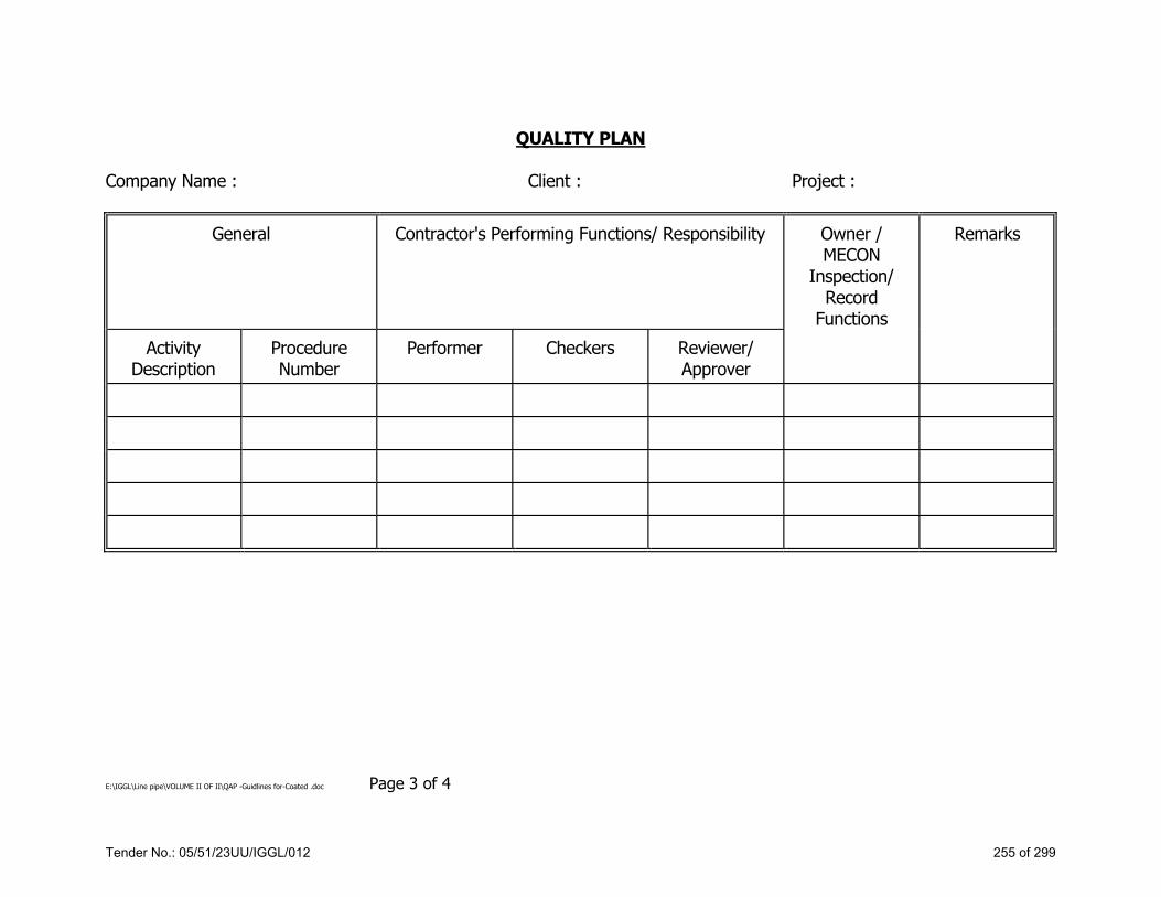
E:\IGGL\Line pipe\VOLUME II OF II\QAP -Guidlines for-Coated .doc Page 3 of 4
QUALITY PLAN Company Name : Client : Project :
General Contractor's Performing Functions/ Responsibility Owner / MECON
Inspection/ Record
Functions
Remarks
Activity Description
Procedure Number
Performer Checkers Reviewer/ Approver
Tender No.: 05/51/23UU/IGGL/012 255 of 299

E:\IGGL\Line pipe\VOLUME II OF II\QAP -Guidlines for-Coated .doc Page 4 of 4
INSPECTION AND TEST PLAN
Sl. No.
Activity Examination by Contractor
Inspection by MECON
Records to be submitted by Contractor
Tender No.: 05/51/23UU/IGGL/012 256 of 299

INSPECTION AND TEST PLAN
FOR STANDARD SPECIFICATION NO.
ELECTRIC WELDED LINE PIPES MEC/TS/05/21/012
(ON SHORE) Page 1 of 4
ITP No. : 05/21/12/001
INSPECTION AND TEST PLAN
FOR
ELECTRIC WELDED LINE PIPES (ON SHORE)
1 OCT 2015 ISSUED FOR IMPLEMENTATION Sachin Singhal Anil Kumar A.K.Sarkar
Rev. No.
Date Purpose Prepared by Checked by Approved by
Tender No.: 05/51/23UU/IGGL/012 257 of 299

INSPECTION AND TEST PLAN
FOR STANDARD SPECIFICATION NO.
ELECTRIC WELDED LINE PIPES MEC/TS/05/21/012
(ON SHORE) Page 2 of 4
ITP No. : 05/21/12/001
SCOPE OF INSPECTION
Sl. No.
Stage Component Characteristics Method of
check Quantum of check
Reference documents
Record MECON Sub
vendorVendor
VENDOR APPOINTED
TPI
MECON /
CLIENT
1a Raw material
inspection HR coil
Chemical Composition CE, PCM, UTS, YS,
%EL, Impact
Review of records &
visual
100% By Supplier & Supplier
appointed TPI and
Random By MECON / CLIENT
PO, Material specification
PO, Material specification
Inspection report
- W W/R W
1B Raw material inspection
HR coil Laminations,
internal imperfection
AUT As per PR Material
specification Material
specification Graphical Recording
- W W R/W
2a Manufacturing, Welding
Rolled pipe Welding
Welding Speed
Current, Voltage,
Frequency, Squeeze out
length
At random Approved
parameters Approved
WPS Internal report
- W W M
2b Manufacturing Pipe Offset, Height of
flash, Trim Visual As per ____ PR, API 5L PR, API 5L
Inspection Report
- W W RW
2c
Manufacturing Procedure
Qualification (1st day
production test)
Pipe
Workmanship, Chemical, Non
destructive examination, Destructive examination
Visual destructive &
Non destructive
tests
As specified in PR
PR PR - W W RW
Tender No.: 05/51/23UU/IGGL/012 258 of 299

INSPECTION AND TEST PLAN
FOR STANDARD SPECIFICATION NO.
ELECTRIC WELDED LINE PIPES MEC/TS/05/21/012
(ON SHORE) Page 3 of 4
ITP No. : 05/21/12/001
Sl. No.
Stage Component Characteristics Method of
check Quantum of check
Reference documents
Record MECON Sub
vendorVendor
VENDOR APPOINTED
TPI
MECON /
CLIENT
3 Heat treatment (if applicable)
Pipe Seam Annealing
Temperature Start & end
length of Annealing
100% PO, Material specification
PO, Material specification
Inspection Report
- W R R
4 Hydro testing Pipe Leak Check Visual
100% by vendor, At random by MECON
Material specification,
PR
Material specification,
PR
Inspection report,
Hydrograph - W W RW
5
Non destructive testing (if
applicable)
Test pipe calibration &
pipes
Surface & internal imperfection
AUT, Eddy current or other as specified
Test pipe & 100% pipe
Technical Specification
Technical Specification
Inspection report,
Graphical record
- W W RW
6 Destructive testing
Pipe Mechanical properties
Tensile Flattening, Reverse Bend,
Hardness, Impact, Micro
(incl. Grain size)
Material specification, 6-71-0005,
PR
Technical Specification
Technical Specification
Lab report - W W RW
7a Final
inspection Pipe
Bevel inspection for cracks, other
defects MPI 100% API 5L, PR API 5L, PR
Inspection report
- W W RW
7b Final inspection
Pipe Ends Inspection for laminations
MUT 100% API 5L, PR API 5L, PR Inspection
report - W W RW
7c Final
inspection Pipe
Residential magnetism
Gauss meter 100% API 5L, PR API 5L, PR Inspection
report - W RW RW
Tender No.: 05/51/23UU/IGGL/012 259 of 299

INSPECTION AND TEST PLAN
FOR STANDARD SPECIFICATION NO.
ELECTRIC WELDED LINE PIPES MEC/TS/05/21/012
(ON SHORE) Page 4 of 4
ITP No. : 05/21/12/001
Sl. No.
Stage Component Characteristics Method of
check Quantum of check
Reference documents
Record MECON Sub
vendorVendor
VENDOR APPOINTED
TPI
MECON /
CLIENT
7d Final
inspection Pipe Pipe
Surface condition,
Straightness, End finish,
Bevel angle, Root face, Outer dia., (Pipe body, Pipe ends),
out of Roundness, Thickness,
Length, Coating, Marking, Colour
coding, End caps
Visual dimensional
100% by vendor, at random by MECON
Technical Specification
Inspection report
- W W RW
8 Weight
checking Pipe Pipe Weight
Weighing scale
100% Technical
Specification Inspection
report - W RW RW
Legends: H- Hold (Offer for witness & obtain clearance), W – Witness, R – Review, RW – Random Witness, A – Approval, I – Information, X – Submit, PO – Purchase Order, PR – Purchase requisition, AUT – Automatic ultrasonic testing, MUT – Manual ultrasonic inspection, MPI – Magnetic particle inspection, M – Monitoring. Regular production shall commence only after tests, calibration, manufacturing procedures and approved and after first day production witness and qualification. All the NDT / Leak testing / Heat treatment / Special manufacturing procedures have to be specially approved or only previously approved procedures have to be used. In case of conflict between purchase specification, contract documents and ITP, Purchase Specification shall be applicable. Note : All items shall be provided with EN 10204-3.2 Certificates.
Tender No.: 05/51/23UU/IGGL/012 260 of 299

INSPECTION AND TEST PLAN
FOR STANDARD SPECIFICATION NO.
LONGITUDINAL SEAM SUBMERGED ARC WELDED LINE PIPES MEC/TS/05/21/012B
(ON SHORE) Page 1 of 6
ITP No. : 05/21/12B/002
INSPECTION AND TEST PLAN
FOR
LONGITUDINAL SEAM SUBMERGED ARC WELDED LINE PIPES (ON SHORE)
1 APR-16 ISSUED FOR IMPLEMENTATION Sachin Singhal Anil Kumar A.K.Sarkar
Rev. No.
Date Purpose Prepared by Checked by Approved by
Tender No.: 05/51/23UU/IGGL/012 261 of 299

INSPECTION AND TEST PLAN
FOR STANDARD SPECIFICATION NO.
LONGITUDINAL SEAM SUBMERGED ARC WELDED LINE PIPES MEC/TS/05/21/012B
(ON SHORE) Page 2 of 6
ITP No. : 05/21/12B/002
1.0 SCOPE:
This Inspection Test Plan covers the minimum testing requirements of LONGITUDINAL SEAM SUBMERGED ARC WELDED LINE PIPES (ON SHORE)
2.0 REFERENCE DOCUMENTS:
1) POIPR/ Standards referred there in Job specifications / Approved documents. 3.0 INPECTION AND TEST REQUIREMENTS:
SL. NO.
STAGE/ACTIVITY CHARACTERISTICS QUANTUM OF
CHECK RECORD
SCOPE OF INSPECTION
Sub Supplier Supplier Supplier
Appointed TPI
MECON / CLIENT
1
Hydro Test, Heat Treatment, NDT, Hot Forming, Expansion And Other Procedures
Documented Procedures. 100% Procedure Documents
- P - R
2 First day production test All testing requirements as per PR
As per PR Test report - H H H
Tender No.: 05/51/23UU/IGGL/012 262 of 299

INSPECTION AND TEST PLAN
FOR STANDARD SPECIFICATION NO.
LONGITUDINAL SEAM SUBMERGED ARC WELDED LINE PIPES MEC/TS/05/21/012B
(ON SHORE) Page 3 of 6
ITP No. : 05/21/12B/002
SL. NO.
STAGE/ACTIVITY CHARACTERISTICS QUANTUM OF
CHECK RECORD
SCOPE OF INSPECTION
Sub Supplier Supplier Supplier
Appointed TPI
MECON / CLIENT
3 Raw Material Inspection Heat No., Plate No., Method of Manufacturing, Heat Treatment Condition
100% By Supplier &
Supplier appointed TPI and Random
By MECON / CLIENT
Inspection Report
- H W W
4 Plate UT 1) 25mm (Min) From Edges 2) 20% Min Coverage In Bal.
Part of late 100%
Inspection Report
- W W
Calibration-W Plate
UT-RW
5 Pipe Forming Bending surface 100% Inspection
Report - W W M
6 Pipe Welding (SAW) 1) Automatic Tack Welding 2) ID & 00 Welding
100% Inspection
Report - W W RW
7 Visual Welding Inspection Examination Of Welding Defects Inside & Outside
100% Inspection
Report - W W RW
Tender No.: 05/51/23UU/IGGL/012 263 of 299

INSPECTION AND TEST PLAN
FOR STANDARD SPECIFICATION NO.
LONGITUDINAL SEAM SUBMERGED ARC WELDED LINE PIPES MEC/TS/05/21/012B
(ON SHORE) Page 4 of 6
ITP No. : 05/21/12B/002
SL. NO.
STAGE/ACTIVITY CHARACTERISTICS QUANTUM OF
CHECK RECORD
SCOPE OF INSPECTION
Sub Supplier Supplier Supplier
Appointed TPI
MECON / CLIENT
8 Cold Expansion Expansion Ratio 100% Inspection
Report . W W RW
9 Hydro Test Leakage & Pressure Drop, Calibration of Gauges Recorder
100% Inspection
Report - W
100% W
RW
10 Calibration of Seam U/T M/C & Final Automatic U/T Inspection
Calibration, Seam Tracking. & Examination of Welding Defects
Calibration -Start & End of Every Shift,
Seam UT 100% By
Supplier & Supplier appointed TPI and Random
By MECON / CLIENT
Inspection Report
- W 100%
W RW
11 Manual Off On Pipe Ends
Lamination 100% Inspection
Report - W
100% W
RW
Tender No.: 05/51/23UU/IGGL/012 264 of 299

INSPECTION AND TEST PLAN
FOR STANDARD SPECIFICATION NO.
LONGITUDINAL SEAM SUBMERGED ARC WELDED LINE PIPES MEC/TS/05/21/012B
(ON SHORE) Page 5 of 6
ITP No. : 05/21/12B/002
SL. NO.
STAGE/ACTIVITY CHARACTERISTICS QUANTUM OF
CHECK RECORD
SCOPE OF INSPECTION
Sub Supplier Supplier Supplier
Appointed TPI
MECON / CLIENT
12 Inspection Of Pipe Ends RT
Welding Defects
203 Mm Length of Both Ends Of
Each Pipe As Per
PR/Specification
RT Films - R Evaluation
of Films R
13 Inspection Of Pipe Ends MPI
1) Examination of Surface Defects After Bevelling. 2) Demagnetisation
100% By Supplier &
Supplier appointed TPI and Random
By MECON / CLIENT
Inspection Report
- H W RW
14 Final Inspection 1) Visual Examination 2) Dimensional Check 3) Weight
100% Inspection
Report - H W RW
15 Mech Properties & Testing
1) Chemical Analysis 2) Tensile Tests of Base Metal 3) Tensile Tests of Weld
(Transverse) 4) Guided Bend Tests 5) Macro & Hardness Tests 6) Impact Tests 7) Dwtt
As Per PR Inspection
Report - H W RW
Tender No.: 05/51/23UU/IGGL/012 265 of 299

INSPECTION AND TEST PLAN
FOR STANDARD SPECIFICATION NO.
LONGITUDINAL SEAM SUBMERGED ARC WELDED LINE PIPES MEC/TS/05/21/012B
(ON SHORE) Page 6 of 6
ITP No. : 05/21/12B/002
SL. NO.
STAGE/ACTIVITY CHARACTERISTICS QUANTUM OF
CHECK RECORD
SCOPE OF INSPECTION
Sub Supplier Supplier Supplier
Appointed TPI
MECON / CLIENT
16 Marking Pipe No, Acceptance No., H.No. , Size, Grade, Thickness & Colour Code
100% Inspection
Report - H W / R RW
NOTES (As applicable): 1. Wherever W/R or H/W is indicated, Inspection Engineer shall decide the option to be exercised for the particular stage and supplier. 2. Supplier's in house procedures may be accepted in case MECON is satisfied with adequacy of procedures to comply with Purchase order /
Specifications requirements. In case of non availability of suitable procedures fresh procedures may be qualified under MECON witness. 3. In case of conflict between purchase specification, contract documents and ITP, more stringent conditions shall be applicable. 4. This document describes generally the requirements pertaining to all types of the item. Requirements specific to PO and the item are only
applicable. 5. Acceptance Norms for all the activities shall be as per PO/PR/STANDARDS referred there in / Job Specification / Approved Documents 6. All items shall be provided with EN 10204-3.2 Certificates.
Legends: CCE or CCOE-Chief Controller of Explosives, DT- Destructive Testing, HT- Heat treatment, H- Hold (Do not proceed without approval), IBR-Indian Boiler Regulations, ITP-Inspection and Test Plan, NDT- Non Destructive Testing, P-Perform., PO- Purchase Order, PR-Purchase Requisition, PQR- Procedure Qualification Record, QAP-Quality Assurance Plan, Random -10% (min. 1 no.) of each size and type of Bulk item, R-Review, RT- Radiography Testing, RW- random Witness, TC-Test Certificate, VDR- Vendor Data Requirements, WPS- Welding Procedure Specification, WPQ- Welders Performance Qualification, W-Witness (Give due notice, work may proceed after scheduled date).
Tender No.: 05/51/23UU/IGGL/012 266 of 299

INSPECTION AND TEST PLAN
FOR STANDARD SPECIFICATION NO.
HELICAL (SPIRAL) SEAM SAW LINE PIPES MEC/TS/05/21/012C
(ON SHORE) Page 1 of 6
ITP No. : 05/21/12C/003
INSPECTION AND TEST PLAN
FOR
HELICAL (SPIRAL) SEAM SAW LINE PIPES (ON SHORE)
1 OCT-15 ISSUED FOR IMPLEMENTATION Sachin Singhal Anil Kumar A.K.Sarkar
Rev. No.
Date Purpose Prepared by Checked by Approved by
Tender No.: 05/51/23UU/IGGL/012 267 of 299

INSPECTION AND TEST PLAN
FOR STANDARD SPECIFICATION NO.
HELICAL (SPIRAL) SEAM SAW LINE PIPES MEC/TS/05/21/012C
(ON SHORE) Page 2 of 6
ITP No. : 05/21/12C/003
1.0 SCOPE:
This Inspection and Test Plan covers the minimum testing requirements of Helical (Spiral) Seam SAW Line Pipes (Onshore) 2.0 REFERENCE DOCUMENTS:
PO/PRI Standards referred there in! Job specifications / Approved documents. 3.0 INSPECTION AND TEST REQUIREMENTS:
S. NO
STAGE/ACTIVITY CHARACTERISTICS QUANTUM OF CHECK
RECORD
SCOPE OF INSPECTION
Sub Supplier
SupplierSupplier
Appointed TPI
MECON / CLIENT
1
Hydro Test, Heat Treatment, Non Destructive Testing, Hot
Forming, Expansion and Other
Procedures
Documented Procedures 100% Procedure Documents
- P - R
2 First day production test All testing requirements as per PR
As per Purchase Requisition
Test report - H H H
3 Raw material inspection Marking & Correlation with TC
100% By Supplier & Supplier
appointed TPI and Random By
MECON / CLIENT
Inspection Report
- H W W
Tender No.: 05/51/23UU/IGGL/012 268 of 299

INSPECTION AND TEST PLAN
FOR STANDARD SPECIFICATION NO.
HELICAL (SPIRAL) SEAM SAW LINE PIPES MEC/TS/05/21/012C
(ON SHORE) Page 3 of 6
ITP No. : 05/21/12C/003
S. NO
STAGE/ACTIVITY CHARACTERISTICS QUANTUM OF CHECK
RECORD
SCOPE OF INSPECTION
Sub Supplier
SupplierSupplier
Appointed TPI
MECON / CLIENT
4 Continuous UT of Plate / Coil 1) 25mm (min) front edges. 2) 20% Min. coverage.
100% by supplier, supplier appointed TPI &
Random by MECON
-do- - H W RW
5 Pipe Welding (Submerged Arc
Welding) Welding parameters, Auto Tracking of weld
100% by supplier, supplier appointed TPI &
Random by MECON
Inspection Report
- H W RW
6 Visual Welding Inspection Examination of welding defects in ID & OD
100% by supplier, supplier appointed TPI &
Random by MECON
-do- - H W RW
7 Hydro testing I) Calibration of pressure gauge 2) Leakage
100% by supplier, supplier appointed TPI &
Random by MECON
-do- - H 100%
W RW
8 Final Automatic
UT Inspection of weld Seam
Internal imperfections of weld seam
100% by supplier, supplier appointed TPI &
Random by MECON
-do- - H 100%
W RW
Tender No.: 05/51/23UU/IGGL/012 269 of 299

INSPECTION AND TEST PLAN
FOR STANDARD SPECIFICATION NO.
HELICAL (SPIRAL) SEAM SAW LINE PIPES MEC/TS/05/21/012C
(ON SHORE) Page 4 of 6
ITP No. : 05/21/12C/003
S. NO
STAGE/ACTIVITY CHARACTERISTICS QUANTUM OF CHECK
RECORD
SCOPE OF INSPECTION
Sub Supplier
SupplierSupplier
Appointed TPI
MECON / CLIENT
9 Manual Ultrasonic Testing of
pipe ends Lamination
100% by supplier, supplier appointed TPI &
Random by MECON
-do- - H 100%
W RW
10 X-ray of pipe ends Internal imperfections of weld seam
203mm on both ends
of each pipe -do- - H
Evaluation of Films
R
11 MPT of beveled edges Examination of surface imperfections after beveling
100% by supplier, supplier appointed TPI &
Random by MECON
Inspection Report
- H 100%
W RW
12 Final Inspection
Pipe
I) Surface condition 2) Straightness 3) End Finish 4) Bevel Angle 5) Root face 6) OD 7) Thickness 8) Square ness 9) Residual Magnetism
100% by supplier, supplier appointed TPI &
Random by MECON
-do- - H 100%
W RW
13 Product Analysis Pipe Chemical composition One sample per heat per lot of
100 pipes -do- - H
100% W
RW
Tender No.: 05/51/23UU/IGGL/012 270 of 299

INSPECTION AND TEST PLAN
FOR STANDARD SPECIFICATION NO.
HELICAL (SPIRAL) SEAM SAW LINE PIPES MEC/TS/05/21/012C
(ON SHORE) Page 5 of 6
ITP No. : 05/21/12C/003
S. NO
STAGE/ACTIVITY CHARACTERISTICS QUANTUM OF CHECK
RECORD
SCOPE OF INSPECTION
Sub Supplier
SupplierSupplier
Appointed TPI
MECON / CLIENT
14 Destructive testing
Pipe
I) Tensile tests of base metal 2) Tensile tests of weld 3) Macro & Hardness test 4) Impact test 5) Guided bends tests 6) Drop weight tear tests 7) Residual stress
One sample per heat per lot of
pipe -do- - H
100% W
RW
15 Marking pipe
Pipe No., Heat Number, Acceptance No., Size, Grade Thickness, API- Monogram & colour coding
100% by supplier
Inspection Report
- H W / R RW
16 Documentation Verification & compliance of inspection & tests reports for submission to client
100% by supplier
Dossier - H H H
Legends: CCE or CCOE-Chief Controller of Explosives, DT- Destructive Testing, HT- Heat treatment, H- Hold (Do not proceed without approval), IBR-Indian Boiler Regulations, ITP-Inspection and Test Plan, NDT- Non Destructive Testing, P-Perform., PO- Purchase Order, PR-Purchase Requisition, PQR- Procedure Qualification Record, QAP-Quality Assurance Plan, Random -10% (min. 1 no.) of each size and type of Bulk item, R-Review, RT- Radiography Testing, RW- random Witness, TC-Test Certificate, VDR- Vendor Data Requirements, WPS- Welding Procedure Specification, WPQ- Welders Performance Qualification, W-Witness (Give due notice, work may proceed after scheduled date).
Tender No.: 05/51/23UU/IGGL/012 271 of 299

INSPECTION AND TEST PLAN
FOR STANDARD SPECIFICATION NO.
HELICAL (SPIRAL) SEAM SAW LINE PIPES MEC/TS/05/21/012C
(ON SHORE) Page 6 of 6
ITP No. : 05/21/12C/003
NOTES (As applicable): 1. Wherever W/R or H/W is indicated, Inspection Engineer shall decide the option to be exercised for the particular stage and supplier. 2. Supplier's in house procedures may be accepted in case MECON is satisfied with adequacy of procedures to comply with Purchase order /
Specifications requirements. In case of non availability of suitable procedures fresh procedures may be qualified under MECON witness. 3. In case of conflict between purchase specification, contract documents and ITP, more stringent conditions shall be applicable. 4. This document describes generally the requirements pertaining to all types of the item. Requirements specific to PO and the item are only
applicable. 5. Acceptance Norms for all the activities shall be as per PO/PR/STANDARDS referred there in / Job Specification / Approved Documents 6. All items shall be provided with EN 10204-3.2 Certificates.
Tender No.: 05/51/23UU/IGGL/012 272 of 299

INSPECTION AND TEST PLAN
FOR STANDARD SPECIFICATION NO.
3-LAYER PE COATING OF LINE PIPES MEC/TS/05/21/014
Page 1 of 5
ITP No. : 05/21/14/004
INSPECTION AND TEST PLAN
FOR
3-LAYER PE COATING OF LINE PIPES
1 APR-2016 ISSUED FOR IMPLEMENTATION Sachin Singhal Anil Kumar A.K.Sarkar
Rev. No. Date Purpose Prepared by Checked by Approved by
Tender No.: 05/51/23UU/IGGL/012 273 of 299

INSPECTION AND TEST PLAN
FOR STANDARD SPECIFICATION NO.
3-LAYER PE COATING OF LINE PIPES MEC/TS/05/21/014
Page 2 of 5
ITP No. : 05/21/14/004
SL. NO. STAGE COMPONENT CHARACTE-
RSTICS METHOD
OF CHECK QUANTUM OF
CHECK REFERENCE DOCUMENTS
ACCEPTANCE NORMS RECORD VENDOR
VENDOR APPOINTED TPI
MECON /
CLIENT
1a Raw material inspection
Epoxy powder, Adhesive polyethylene compound, shots, grils and chronic acids and
phosphoric acids
Batch nos. and date of
manufacturing and correlation with
MTC
Review of records &
visual 100% PO, Material
specification
PO, Material specification for each batch of raw material used in PQT
Inspection report W R R
1b Raw material inspection
Epoxy powder, Adhesive polyethylene compound, shots, grils and chronic acids and
phosphoric acids
In addition to mfc, contractor shall test
samples as per spec.
In-house testing
One Sample per each batch per
item
PO, Material specification
PO, Material specification
Inspection report W W W
2a Surface
preparation (1st blast cleaning)
Each bare pipe
Oil free, preheating, blast cleaning and
free from salt contamination, phosphoric and
treatment followed by De-ionized water wash
As per internal QA
Plan 100% QA plan Internal standard Inspection
report W W/R W/R
2b Surface
preparation (2nd blast cleaning)
Each bare pipe
Relative humidity, degree of cleaning, degree of dust and
roughness
As per internal QA
Plan 100% QA plan PO,
specifications Inspection
report W W/R W/R
3 Chromate treatment Each bare pipe
Application as per manufacturer’s
recommendation and data sheet
As per internal QA
Plan 100% QA plan PO,
specifications Inspection
report W W/R W/R
4 Coating
application 1) Pipe heating
Each bare pipe
Pre-heating pipe surface
temperature prior to epoxy powder
application
Infrared camera/thermal sticks
100% QA plan PO, specifications
Inspection report W W/R W/R
Tender No.: 05/51/23UU/IGGL/012 274 of 299

INSPECTION AND TEST PLAN
FOR STANDARD SPECIFICATION NO.
3-LAYER PE COATING OF LINE PIPES MEC/TS/05/21/014
Page 3 of 5
ITP No. : 05/21/14/004
SL. NO. STAGE COMPONENT CHARACTE-
RSTICS METHOD
OF CHECK QUANTUM OF
CHECK REFERENCE DOCUMENTS
ACCEPTANCE NORMS RECORD VENDOR
VENDOR APPOINTED TPI
MECON /
CLIENT
5 2) Epoxy powder
application Each pipe
Application as per manufacturer’s
recommendation and data sheet
Set pressures
and thickness
100% QA plan PO, specifications
Inspection report W W/R W/R
6 3) Adhesive
layer application
Each pipe
Application as per manufacturer’s
recommendation and data sheet
Film Thickness 100% QA plan PO,
specifications Inspection
report W W/R W/R
7 PE Layer application Each pipe
PE Film application temperature,
finished coating thickness
Film thickness 100% QA plan PO,
specifications Inspection
report W W/R W/R
7a Final inspection Each pipe Visual &
identification Visual 100% QA plan PO, specifications
Inspection report W W/R W/R
8 Coating
procedure & qualification
(PQT)
Tests on pipe coated partly with epoxy and partly with epoxy &
adhesive layers
Air pressure, Application window, dew point of dry air
As per PQT procedures
and specificatio
ns
5 samples from coated pipes/as
per specifications for each pipe
diameter\, and for each plant
QA plan PO, specifications
Inspection report H H H
8a Tests on pipe coated with
all three layers
Coated pipe
1) Impact test 2) Indentation 3) Elongation 4) Bond strength
As per specification and PQT requiremen
ts
1) Min. 30 impacts on body along, the length, no holiday allowed.
2) Two samples for both temp.
3) Six samples from 3 coated pipes
4) From 3 coated pipes
QA plan PO, specifications
Inspection report H H H
Tender No.: 05/51/23UU/IGGL/012 275 of 299

INSPECTION AND TEST PLAN
FOR STANDARD SPECIFICATION NO.
3-LAYER PE COATING OF LINE PIPES MEC/TS/05/21/014
Page 4 of 5
ITP No. : 05/21/14/004
SL. NO. STAGE COMPONENT CHARACTE-
RSTICS METHOD
OF CHECK QUANTUM OF
CHECK REFERENCE DOCUMENTS
ACCEPTANCE NORMS RECORD VENDOR
VENDOR APPOINTED TPI
MECON /
CLIENT
8b Tests on pipe coated with
all three layers
Coated pipe
1) Cathodic disbondment
2) Holiday inspection
3) Coating thickness
4) Visual inspection
As per specificatio
n
1) One sample 2) On all pipes 3) On all points 4) On all pipes
QA plan PO, PR & specifications
Inspection report W W W
9 On line
inspection and testing
Coated pipe Start of production
By thickness
gauge epoxy thk. Adhesive
thk.
Start of production, i.e.
first pipe QA plan PO, PR &
specifications Inspection
report W W W
9a Holi day
detection at 25 kV
Coated pipe To find surface discontinuities
Holiday detector Every pipe QA plan Inspection
report W W/R W/R
9b Overall coating
thckness Each coated pipe Thickness of
coating Every pipe Every pipe QA plan PO, PR & specifications
Inspection report W W/R W/R
10 Off line tests a) Impact test Coated pipe Energy absorbed
by impact Impact test instrument
Two pipes per shift QA plan PO, PR &
specifications Inspection
report W W W
10a ERsistance to peel test Coated pipe To measure peel
load Peel test machine
One in 15 pipes / as per
specification QA plan PO, PR &
specifications Inspection
report W
W
W
Tender No.: 05/51/23UU/IGGL/012 276 of 299

INSPECTION AND TEST PLAN
FOR STANDARD SPECIFICATION NO.
3-LAYER PE COATING OF LINE PIPES MEC/TS/05/21/014
Page 5 of 5
ITP No. : 05/21/14/004
SL. NO. STAGE COMPONENT CHARACTE-
RSTICS METHOD
OF CHECK QUANTUM OF
CHECK REFERENCE DOCUMENTS
ACCEPTANCE NORMS RECORD VENDOR
VENDOR APPOINTED TPI
MECON /
CLIENT
10b Resistence to
indentation test
Coated pipe
Indentation bath, with
heater, dial gauge &
thermostat
Two pipes per shift QA plan PO, PR &
specifications Inspection
report W W W
Legends: H- Hold (Offer for witness & obtain clearance), W – Witness, R – Review, A – Approval, I – Information, X – Submit, PO – Purchase Order, PR – Purchase requisition, N – Normalizing & Tempering, SA – Solution annealing, N & SR – Normalizing & Stress relieving, PR – Purchase Requisition, Ref. Doc: ASTM D-149, D-257, D-570, D-638, G-42 & DIN 53735 and SIS 055900.
All the NDT / Leak testing / Heat treatment / Special manufacturing procedures have to be specially approved or only previously approved procedures have to be used. In case of conflict between purchase specification, contract documents and ITP more stringent conditions shall be applicable. This document describes generally the requirements pertaining to 3-layer PE coating of pipes. All items shall be provided with EN 10204-3.2 Certificates.
Tender No.: 05/51/23UU/IGGL/012 277 of 299

INSPECTION AND TEST PLAN FOR
INTERNAL LIQUID EPOXY COATING
STANDARD SPECIFICATION NO. MEC/TS/05/21/014B
Page 1 of 7
ITP.: 05/21/14B/005
INSPECTION AND TEST PLAN
FOR
INTERNAL LIQUID EPOXY COATING
1 APR-16 ISSUED FOR IMPLEMENTATION Sachin Singhal Anil kumar
Rev. No. Date Purpose Prepared & Checked by
Approved by
Tender No.: 05/51/23UU/IGGL/012 278 of 299

INSPECTION AND TEST PLAN FOR
INTERNAL LIQUID EPOXY COATING
STANDARD SPECIFICATION NO. MEC/TS/05/21/014B
Page 2 of 7
ITP.: 05/21/14B/005
1.0 SCOPE:
This Inspection Test Plan covers the minimum testing requirements of Internal Coating.
2.0 REFERENCE DOCUMENTS:
1) PO/PR/ Standards referred there in / Job specifications / Approved documents.
3.0 INPECTION AND TEST REQUIREMENTS:
SL.
NO. STAGE/ACTIVITY CHARACTERISTICS
QUANTUM OF CHECK
RECORD SCOPE OF INSPECTION
VENDOR
VENDOR APPOINTED
TPI
MECON/ CLIENT
1a Raw Material Inspection of Coating Paint & Hardener
Batch No. Date of manufacturing, correlation with MTC, properties
100% Inspection
Report W W R
1b
Raw Material Inspection of Coating Paint & Hardener for qualification of coating material
In addition to MTC review, contractor shall test sample as per specification as minimum but not limited to following: a) Non-volatile matter (by mass) b) Non-volatile matter (by volume) c) Viscosity d) Density e) Ash residue on ignition f) Pot life
Each Batch
Check
Test
Report
W W W/R
Tender No.: 05/51/23UU/IGGL/012 279 of 299

INSPECTION AND TEST PLAN FOR
INTERNAL LIQUID EPOXY COATING
STANDARD SPECIFICATION NO. MEC/TS/05/21/014B
Page 3 of 7
ITP.: 05/21/14B/005
SL.
NO. STAGE/ACTIVITY CHARACTERISTICS
QUANTUM OF CHECK
RECORD SCOPE OF INSPECTION
VENDOR
VENDOR APPOINTED
TPI
MECON/ CLIENT
2
Surface preparation (Visual appearance prior to blast cleaning) Inside surface of each pipe
Free from foreign matter, welding flux, spatters, salts, oil & grease
100% Inspection
Report W W S
3a
Surface preparation (Visual appearance prior to blast cleaning) Inside surface of each pipe
Free from visual damage & other contaminations, surface, irregularities, dent, lap etc.
100% Inspection
Report W W S
3b Surface preparation (after blast cleaning) Inside surface of pipe
Degree of cleanliness / dust 1/10 Pipes Inspection
Report W W S
3c Surface preparation (after blast cleaning) Inside surface of pipe
Surface profile / roughness / surface preparation
1/10 Pipes Inspection
Report W W S
4
Paint preparation (Wet paint mixture) Paint Mix ratio as per manufacturer recommendation
Viscosity & Temperature
Each time paint is mixed & at time of interruption if any and each start of shift
Inspection
Report W W W/R
5 Environmental conditions Plant conditions
Ambient temperature, pipe surface temp., relative humidity, dew point
Once every 4 hours
Inspection
Report W W W/R
Tender No.: 05/51/23UU/IGGL/012 280 of 299

INSPECTION AND TEST PLAN FOR
INTERNAL LIQUID EPOXY COATING
STANDARD SPECIFICATION NO. MEC/TS/05/21/014B
Page 4 of 7
ITP.: 05/21/14B/005
SL.
NO. STAGE/ACTIVITY CHARACTERISTICS
QUANTUM OF CHECK
RECORD SCOPE OF INSPECTION
VENDORVENDOR
APPOINTED TPI
MECON/ CLIENT
6
Cured paint film on steel panel, 5 no. sample Procedure qualification test and repair procedure qualification test
1) Adhestion test 2) Buchholz hardness 3) Resistance to neutral salt
spray 4) Resistance to artificial
ageing 5) Bend test (conical Mandrel) 6) Resistance to gas pressure
variation 7) Resistance to water
immersion 8) Resistance to chemicals 9) Resistance to hydraulic
blistering 10) Porosity (glass panel dry
+wet) 11) WFT (on all 25 pipes) 12) DFT (on all 25 pipes)
On start of production / each change of
manufacturer / each change of
manufacturer / each change of plant (5 No. pipes to be selected
from coated 25 pipes)
PQT Document /
Report W W H
7 Coating inspection (on pipe) Inside Coating of Pipe
a) Appearance and continuity Each pipe Inspection
Report W W W/R
b) WET Film Thickness
Each hour of production (at 4 circumferential
equidistance points on both ends of pipes)
Inspection
Report W W W/R
Tender No.: 05/51/23UU/IGGL/012 281 of 299

INSPECTION AND TEST PLAN FOR
INTERNAL LIQUID EPOXY COATING
STANDARD SPECIFICATION NO. MEC/TS/05/21/014B
Page 5 of 7
ITP.: 05/21/14B/005
SL.
NO. STAGE/ACTIVITY CHARACTERISTICS
QUANTUM OF CHECK
RECORD SCOPE OF INSPECTION
VENDORVENDOR
APPOINTED TPI
MECON/ CLIENT
c) Porosity (Pinhole)* At start of production,
change of paint / hardener batch, interruption if any
Inspection
Report W W W/R
d) DFT (At Yard) Each pipe Inspection
Report W W W/R
e) Visual & cut back length Each pipe
Inspection
Report W W W/R
8 Coating Repair Internal Coating Repair
Defective coating Each defective pipe Repair
Inspection Report
W W W/R
9 Cured paint film on steel test panel Regular production test
a) Adhesion test 2/Shift Inspection
Report W W W/R
b) Bend Test 2/Shift Inspection
ReportW W W/R
c) Buchholz Hardness 2/Shift
Inspection
Report W W W/R
Tender No.: 05/51/23UU/IGGL/012 282 of 299

INSPECTION AND TEST PLAN FOR
INTERNAL LIQUID EPOXY COATING
STANDARD SPECIFICATION NO. MEC/TS/05/21/014B
Page 6 of 7
ITP.: 05/21/14B/005
SL.
NO. STAGE/ACTIVITY CHARACTERISTICS
QUANTUM OF CHECK
RECORD SCOPE OF INSPECTION
VENDORVENDOR
APPOINTED TPI
MECON/ CLIENT
d) Curing Test 2/Shift
Inspection
ReportW W W/R
10 Paint film on glass test panels Regular production test
* Porosity (PINHOLE) both wet film and dry film
2/Shift and each new batch
Inspection
Report W W W/R
11 Pipe handling and storage Storage in yard
Secured handling & storage Accepted coated pipesInspection
Report W W S
12 Calibration of instruments Calibration of thermometer, thickness gauge, roughness, gauge etc.
Once / Shift Calibration
Report W W S
13 Final Documents Final Documents completion
Each Set
H H H
* The wet sponge test shall be carried out if the porosity on glass panels constitute a failure as per ISO 15741 Annexure G
Legends: CCE or CCOE-Chief Controller of Explosives, DT- Destructive Testing, HT- Heat treatment, H- Hold (Do not proceed without approval), IBR-Indian Boiler Regulations, ITP-Inspection and Test Plan, M- Monitor, NDT- Non Destructive Testing, O - Observer, P- Perform., PO- Purchase Order, PR-Purchase Requisition, PQR- Procedure Qualification Record, QAP-Quality Assurance Plan, Random - 10% (min. 1 no.) of each size and type of Bulk item, R-Review, RT- Radiography Testing, RW- random Witness, S - Surveillance inspection, TC-Test Certificate, TPI or TPIA - Third party inspection agency, VDR- Vendor Data Requirements, WPS- Welding Procedure Specification, WPQ- Welders Performance Qualification, W-Witness (Give due notice, work may proceed after scheduled date).
All items shall be provided with EN 10204-3.2 Certificates.
Tender No.: 05/51/23UU/IGGL/012 283 of 299
INSPECTION AND TEST PLAN FOR
INTERNAL LIQUID EPOXY COATING
STANDARD SPECIFICATION NO. MEC/TS/05/21/014B
Page 7 of 7
ITP.: 05/21/14B/005
NOTES (As applicable): 1) Wherever W/R or H/W is indicated, MECON Inspection Engineer shall decide the option to be exercised for the particular
stage and supplier. 2) Supplier's in house procedures may be accepted in case MECON is satisfied with adequacy of procedures to comply with
Purchase order / Specifications requirements. In case of non availability of suitable procedures fresh procedures may be qualified under MECON witness.
3) In case of conflict between purchase specification, contract documents and ITP, more stringent conditions shall be applicable.
4) This document describes general1y the requirements pertaining to all types of the item. Requirements specific to PO and the item are only applicable.
5) Acceptance Norms for all the activities shall be as per PO/PR/STANDARDS referred there in / Job Specification / Approved Documents.
Tender No.: 05/51/23UU/IGGL/012 284 of 299

INSPECTION AND TEST PLAN
FOR STANDARD SPECIFICATION NO.
SEAMLESS PIPES MEC/TS/05/21/012A Page 1 of 4
ITP No. : 05/21/012A/001
INSPECTION AND TEST PLAN
FOR
SEAMLESS PIPES
0 SEP-2017 ISSUED FOR IMPLEMENTATION Sachin Singhal Anil Kumar
Rev. No. Date Purpose Prepared &
Checked by Approved by
Tender No.: 05/51/23UU/IGGL/012 285 of 299

INSPECTION AND TEST PLAN
FOR STANDARD SPECIFICATION NO.
SEAMLESS PIPES MEC/TS/05/21/012A Page 2 of 4
ITP No. : 05/21/012A/001
SCOPE OF INSPECTION
1.0 SCOPE :
This Inspection Test Plan covers the minimum testing requirements of SEAMLESS PIPES.
2.0 REFERENCE DOCUMENTS: 1) PO / PR / Standards referred there in / Job specifications / Approved documents.
3.0 INSPECTION AND TEST REQUIREMENTS:
SL. NO. STAGE / ACTIVITY CHARACTERISTICS QUANTUM OF CHECK RECORD
SCOPE OF INSPECTION
VENDOR VENDOR
APPOINTED TPI
MECON / CLIENT
1a Raw Material Inspection Marking And Correlation With Tc 100% Inspection Report W R R
1b Raw Material Inspection Chemical Composition One Sample per Heat Inspection Report R R R
1c Raw Material Inspection Internal Soundness One Sample per Heat Inspection Report W - -
2 Pipe Rolling Heating, Hot Rolling, Straightening Process Controls As per internal QA Plan Inspection Report W - -
Tender No.: 05/51/23UU/IGGL/012 286 of 299

INSPECTION AND TEST PLAN
FOR STANDARD SPECIFICATION NO.
SEAMLESS PIPES MEC/TS/05/21/012A Page 3 of 4
ITP No. : 05/21/012A/001
SL. NO. STAGE / ACTIVITY CHARACTERISTICS QUANTUM OF CHECK RECORD
SCOPE OF INSPECTION
VENDOR VENDOR
APPOINTED TPI
MECON / CLIENT
3 Heat Treatment (If Applicable) HT Cycle (Time & Temperature) 100% Inspection Report W R R
4 Non Destructive Testing (If Applicable)
Surface & Internal Imperfections PO, Material Specification Inspection Report,
Graphical Record W R R
5 Destructive Testing
(Note Special Impact, Hardness, Requirements For Hz Service)
Chemical & Mechanical Properties
Each HT Lot / Each Heat No. / Size Lab Report H H H
6 Destructive Testing (For SS Materials) Corrosion Properties
Highest Thickness & Highest
Carbon / HT Lot Lab Report H H H
7 Hydro Testing Leak Check 100 % By Supplier,
At Random By MECON / TPIA
Inspection Report, Hydro Graph H H H
8. Final Inspection
Surface Condition, Straightness, End Finish, Bevel Angle, Root Face, Outer Dia., Thickness,
Length, End Finish, Coating, Marking, Colour
Coding, End Caps,
100 % By Supplier, At Random By MECON /
TPIA Inspection Report H H H
9. Weight Checking Weight 100% Inspection Report W - -
10. Final Inspection (For AS/SS Pipe) PMI Check As per Specification No. MEC/TS/05/21/012D Inspection Report H RW RW
Tender No.: 05/51/23UU/IGGL/012 287 of 299

INSPECTION AND TEST PLAN
FOR STANDARD SPECIFICATION NO.
SEAMLESS PIPES MEC/TS/05/21/012A Page 4 of 4
ITP No. : 05/21/012A/001
Legends: CCE or CCOE-Chief Controller of Explosives, DT- Destructive Testing, HT- Heat treatment, H- Hold (Do not proceed without approval), IBR-Indian Boiler Regulations, ITP-Inspection and Test Plan, M- Monitor, NDT- Non Destructive Testing, P-Perform, PO- Purchase Order, PR-Purchase Requisition, PQR- Procedure Qualification Record, QAP-Quality Assurance Plan, Random -10% (min. l no.) of each size and type of Bulk item, R-Review, RT- Radiography Testing, RW- Random Witness, TC-Test Certificate, TPI or TPIA - Third Party Inspection Agency, VDR- Vendor Data Requirements, WPS- Welding Procedure Specification, WPQ- Welders Performance Qualification, W-Witness (Give due notice, work may proceed after scheduled date). NOTES (As applicable): 1. Wherever W/R or H/W is indicated, MECON Inspection Engineer shall decide the option to be exercised for the particular stage and supplier. 2. Supplier's in house procedures may be accepted in case TPI / MECON is satisfied with adequacy of procedures to comply with Purchase Order / Specifications
requirements. In case of non availability of suitable procedures, fresh procedures may be qualified under TPI / MECON witness. 3. In case of conflict between purchase specification, contract documents and ITP, more stringent conditions shall be applicable. 4 This document describes generally the requirements pertaining to all types of the item. Requirements specific to PO and the item are only applicable. 5. Acceptance Norms for all the activities shall be as per PO / PR / STANDARDS referred there in / Job Specification / Approved Documents. 6. All items shall be provided with EN 10204-3.2 Certificates.
Tender No.: 05/51/23UU/IGGL/012 288 of 299

STANDARD SPECIFICATION
NO. MEC/TS/05/21/012E
ITP No. : ITP No. : 05/21/12B/006
Raw Material (HR COIL/PLATE) Quality Requirements for Line Pipes
1 APR-16 ISSUED FOR IMPLEMENTATION Sachin Singhal K.P.Singh O.P.Jain
Rev.
No. Date Purpose Prepared by Checked by Approved by
Tender No.: 05/51/23UU/IGGL/012 289 of 299

STANDARD SPECIFICATION
NO. MEC/TS/05/21/012E
ITP No. : ITP No. : 05/21/12B/006
1.0 SCOPE:
This Inspection and Test Plan covers the minimum inspection & testing requirements for Rolling process for manufacturing of Hot Rolled Coil & Plates as part of raw material quality requirements for line pipes
2.0 INSPECTION AND TEST REQUIREMENTS:
Client :
Standards : Date :--------------
Size & Grade :
Page no.
:
Scope Of Inspection
NO Sl. No. Components & Operations
Characteristics/ Type of check
Quantum ofcheck
Reference document and Acceptance norm Responsibility
Format of records
Steel Manuf.
Pipe Manuf.&
TPI
MECON / CLIENT
1 2 3 4 5 6 7 8 9 10 11
2
Rolling
department
Slab
preheating
Heating
parameters per zone
1 slab/Heat
As per Steel Manuf. control level and
acceptance as per Tender Requirement
Quality
In-charge
Report as per Steel Mill
format P
RW (20%)
M
3
Hot rolling department
Rolling and accelerated
cooling of coils
Rolling parameters
and temperature tolerances.
1 coil/Plate per Heat
As per Steel Manuf. control level and
acceptance as per Tender Requirement
Quality In-charge
Report as per Steel Mill
format P
RW (20%)
M
Tender No.: 05/51/23UU/IGGL/012 290 of 299

STANDARD SPECIFICATION
NO. MEC/TS/05/21/012E
ITP No. : ITP No. : 05/21/12B/006
4 Ultrasonic of
plates
Automatic Ultrasonic machine
Internal imperfections&
lamination 1 Plate/Heat
As per Steel Manuf. control level and
acceptance as per Tender Requirement
Quality In-charge
Report as per Steel Mill
format P
W
RW
5
Sampling
department
Sample removal
Check sample position (end or
within body)
1 coil/Plate per Heat
As per Steel Manuf. control level and
acceptance as per Tender Requirement
Quality
In-charge
Report as per Steel Mill
format P
W
RW
6
Sampling
department
Inspection of coil end
surface quality and
dimensions
Surface of
coil
1 coil/Plate per Heat
As per Steel Manuf. control level and
acceptance as per Tender Requirement
Quality
In-charge
Report as per Steel Mill
format P
RW
M
7
Sampling
department
Mechanical, chemical and
hardness tests
Chemical analysis,
Tensile Test, Bend Test,
Impact Test, Hardness Test,
DWTT Test Ferritic Grain
Size
1 coil/Plate
per Heat
As per Steel Manuf. control level and
acceptance as per Tender Requirement
Quality
In-charge
Report as per Steel Mill format &
inspections reports
P
W
RW(Minimum 20% of Total
Heats)
Tender No.: 05/51/23UU/IGGL/012 291 of 299

STANDARD SPECIFICATION
NO. MEC/TS/05/21/012E
ITP No. : ITP No. : 05/21/12B/006
8
Packing and
shipping department
Marking
No hard stamping
Each
coil/Plate
As per Steel Manuf. control level and
acceptance as per Tender Requirement
Quality
In-charge
Report as per Steel Mill
format P
RW
M
9
Packing and
shipping department
Production of
test certificates
Manuf.
INSPECTION CERTIFICATE
as per EN 10204-3.2
Each heat of Coil &
plate
As per Steel Manuf. control level and
acceptance as per Tender Requirement
Quality
In-charge
Report as per Steel Mill
format P C R
10
Packing and
shipping department
Shipping
Correct loading
Each
coil/Plate
As per Steel Manuf. control level and
acceptance as per Tender Requirement
Quality
In-charge
Report as per Steel Mill
format P RW H
NOTES (As applicable):
1. Successful pipe Manufacturer has to submit latest audit report of offered Coil /Plate mill along with Inspection Test plan.
2. Wherever W/R is indicated, Inspection Engineer shall decide the option to be exercised for the particular stage and supplier.
3. Wherever RW is indicated, Inspection engineer shall witness at least 10% quantity (Minimum 1No.) randomly in a specific time interval.
4. Steel Manufacture’s in house procedures may be accepted in case MECON is satisfied with adequacy of procedures
Legends:, HT- Heat treatment, H- Hold (Do not proceed without approval), , ITP-Inspection and Test Plan, NDT- Non Destructive Testing, P-Perform(100%)., PO- Purchase Order, PR-Purchase Requisition, QAP-Quality Assurance Plan, RW-Random witness-Min 10% or min. 1 no. (Whichever is higher), R-Review, TC-Test Certificate, , W-Witness (Give due notice, work may proceed after scheduled date).,M-Monitor, C-Certify
Tender No.: 05/51/23UU/IGGL/012 292 of 299

STANDARD SPECIFICATION
NO. MEC/TS/05/21/012E
ITP No. : ITP No. : 05/21/12B/006
to comply with Purchase order / Specifications requirements. In case of non availability of suitable procedures, fresh procedures may be submitted to MECON.
5. In case of conflict between purchase specification, contract documents and ITP, more stringent conditions shall be applicable.
6. The Line Pipe Manufacturer shall be completely responsible for the design, materials, testing, inspection, preparation for shipment, loading of the supplied item strictly in accordance with the Material Requisition and all attachments thereto.
7. Inspection by MECON would be only to review/witness the requirement of the material for pipe manufacturing and no way absolve the Line pipe manufacturer of his responsibility/contractual obligation to comply with PR requirements, applicable codes, specifications and statutory rules/regulations. Any error/deficiency noticed during any stage of manufacturing/inspection/execution/installation shall be promptly corrected by the line pipe manufacturer without any extra cost or time, whether or not comments on the same were received from MECON during the inspection/other stage.
8. Line pipe manufacturer has to give at least 3 weeks advance notice for inspection to Mecon/CLIENT. 9. All items shall be provided with EN 10204-3.2 Certificates. 10. Scope of inspection for Quantity less than 10,000MT shall be finalized after award of contract.
Tender No.: 05/51/23UU/IGGL/012 293 of 299

Tender No.: 05/51/23UU/IGGL/012 294 of 299

Tender No.: 05/51/23UU/IGGL/012 295 of 299
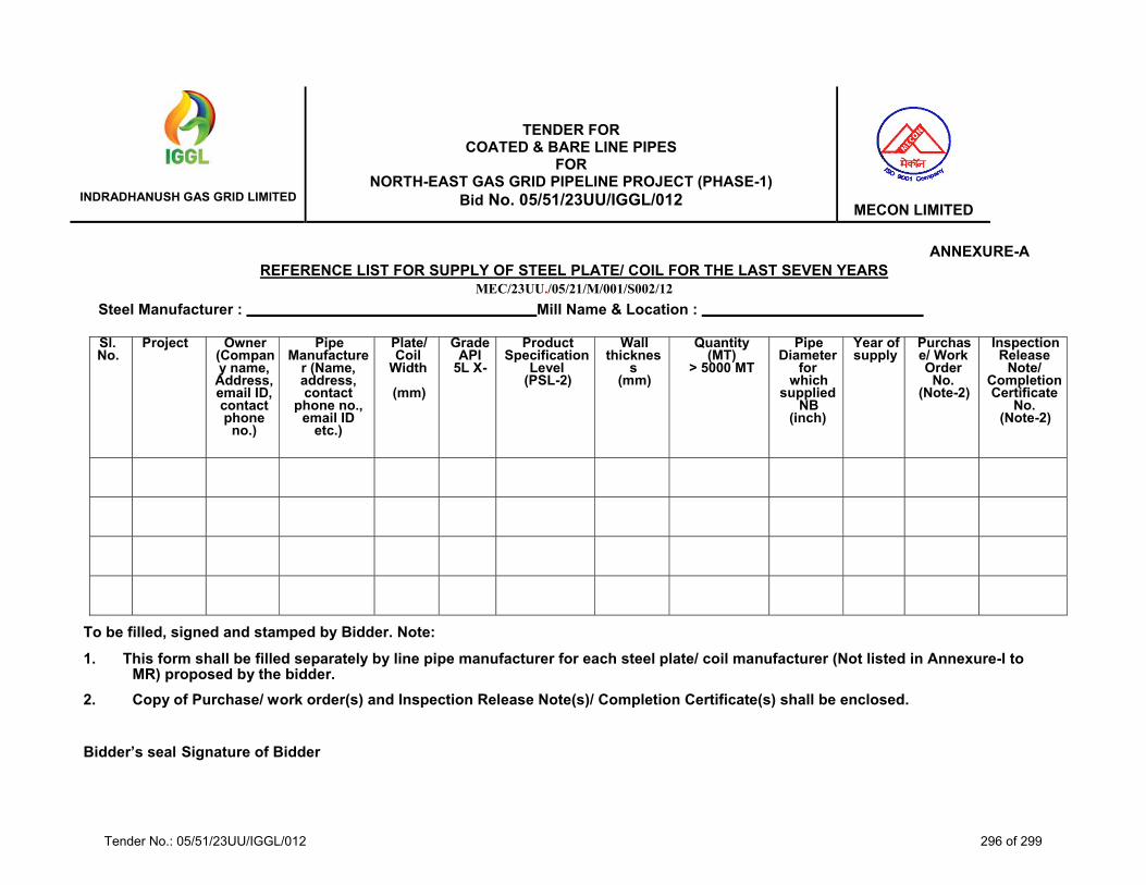
INDRADHANUSH GAS GRID LIMITED
TENDER FOR COATED & BARE LINE PIPES
FOR NORTH-EAST GAS GRID PIPELINE PROJECT (PHASE-1)
Bid No. 05/51/23UU/IGGL/012
MECON LIMITED
ANNEXURE-A REFERENCE LIST FOR SUPPLY OF STEEL PLATE/ COIL FOR THE LAST SEVEN YEARS
MEC/23UU./05/21/M/001/S002/12
Steel Manufacturer : Mill Name & Location :
Sl. No.
Project Owner (Company name,
Address, email ID, contact phone
no.)
Pipe Manufacture
r (Name, address, contact
phone no., email ID
etc.)
Plate/ Coil
Width
(mm)
GradeAPI
5L X-
Product Specification
Level (PSL-2)
Wall thicknes
s (mm)
Quantity(MT)
> 5000 MT
Pipe Diameter
for which
suppliedNB
(inch)
Year of supply
Purchase/ Work Order
No. (Note-2)
Inspection Release
Note/ Completion Certificate
No. (Note-2)
To be filled, signed and stamped by Bidder. Note:
1. This form shall be filled separately by line pipe manufacturer for each steel plate/ coil manufacturer (Not listed in Annexure-I to MR) proposed by the bidder.
2. Copy of Purchase/ work order(s) and Inspection Release Note(s)/ Completion Certificate(s) shall be enclosed.
Bidder’s seal Signature of Bidder
Tender No.: 05/51/23UU/IGGL/012 296 of 299

Page 1 of 3ANNEXURE-II
Sl.No.
BEC Clause No.(Ann-I to IFB -
Vol-I)
Description & Documents Required Submitted(Bidder to indicate Yes/ No)
Reference in Bid Document
(Bidder to indicate place in the bid, such as Page No./ Vol. No.
etc.)
FOR BARE PIPE3.1.1.1 (01) 0Bidder shall have minimum domestic value addition of 15% on inputs such as Plate/HR coils as applicable for
manufacturing of Steel pipes against each quoted items & has to submit the affidavit for the same.- Copy of affidavit as per format given in the tender
1 3.1.1.1 (02) The Line Pipe Manufacturer shall be a manufacturer of API 5L PSL-2 (or equivalent) quality line pipes and shallhave a valid license to use API 5L monogram on Line pipe with product specification level PSL-2 quality for theproposed pipe mill(s).Submit the following documents in support of above- Copy of valid API 5L Certificate with PSL-2 quality for the proposed mill(s)
2 3.1.1.1 (03) The Line Pipe Manufacturer should have manufactured and supplied from proposed pipe mill(s) at least 1 km of linepipes of type as quoted in one single order in one single order as per API 5L PSL-2 or equivalent that are of equalor higher in terms of diameter ,wall thickness and grade as quoted for, in any of the last seven years reckoned fromthe due date of submission of bid.
(i) Copy of relevant Purchase Order (PO). (ii) Inspection Certificate / Release Note (iii) Completion Certificate against referred P.O.
3 3.1.1.1 (04) In addition, line pipe manufacturer should have manufactured and supplied from proposed pipe mill (s) at least 10%of the quoted quantity of line pipes in single order as per API 5L PSL 2 (or equivalent) of Grade X-65 or higher foritems A1, A2 & B1 ,that are of same type, equal or higher in terms of diameter with minimum wall thickness of 9.5mm or higher for the items A1 & A2 and 6.4 mm or higher for the item B1as quoted for, in last 07 (seven) yearsreckoned from the bid due date.Submit the following documents in support of above(i) Copy of relevant Purchase Order (PO) / Letter of Award (LOA) (ii) Inspection Certificate / Release Note (iii) Completion Certificate against referred P.O.
4 3.1.1.1 (05) The Mill Qualification : The bidder shall furnish a certificate for proposed pipe mills along with their bid, which havenot been audited by IGGL / or its authorized representatives or, have not supplied pipes to IGGL of same or highersize and material Grade as quoted for or higher grade during last (7) seven years reckoned from the due date ofsubmission of bid, as per Format provided in the bid document, from a reputed International inspection agency (i.e.BV/CEIL/ LLOYDS/ DNV/ TUV/ ABS/ MOODY/AIB-Vincotte), certifying that the mill has capability to produce linepipes complying with technical requirements specified in the bid documents.
Non-compliance to the above requirement will make the mill liable for rejection.
The mill capability certificate from one of the above mentioned reputed agencies for the proposed mill for same orhigher size, wall thickness and material grade of same type as quoted for or higher grade, issued in the last 12months, reckoned from the bid due date, for any of IGGL projects shall be considered acceptable for this projectalso.
Submit the following documents in support of above- Capability Certificate format certified by International Inspection Agency as mentioned.
5 3.1.1.1 (06) The Bidder shall procure Steel Rounds/Billets/Blooms/HR coils/Plates from the steel Rounds/Billets/Blooms/HRcoils/Plates manufacturer as per list provided in bid document. In addition, the bidder may submit more names, ifthey so desire, which shall be evaluated during bidding stage based on the criteria mentioned in the bid document.The techno-commercially qualified bidder(s) will be informed prior to price bid opening on acceptance of theproposed steel Rounds/Billets/Blooms/HR coils/Plates manufacturer(s), if any. Bidder’s offer shall be unconditionalirrespective of finally qualified steel Rounds/Billets/Blooms/HR coils/Plates manufacturer(s).
TThe list of accepted Rounds/Billets/Blooms/HR coils/Plates manufacturer(s) other than specified in the biddocument will also be intimated to all the techno-commercial acceptable bidders once techno-commercialevaluation of bids is finalized.
Submit the Letter of Confirmation for the same from 2(two) nos Steel Plate/ Coil/Billet/RoundManufacturer's..
CHECK LIST FOR SUBMISSION OF DOCUMENTS REQUIRED FOR BID EVALUATION NORTH-EAST GAS GRID PIPELINE PROJECT (PHASE-1)
BID DOCUMENT NO.: 05/51/23UU/IGGL/012DOCUMENTS REQUIRED FOR BID EVALUATION (TECHNICAL)
(Bidder's Signature & Seal)Tender No.: 05/51/23UU/IGGL/012 297 of 299

Page 2 of 3ANNEXURE-II
Sl.No.
BEC Clause No.(Ann-I to IFB -
Vol-I)
Description & Documents Required Submitted(Bidder to indicate Yes/ No)
Reference in Bid Document
(Bidder to indicate place in the bid, such as Page No./ Vol. No.
etc.)
6 3.1.1.1 (07) Bidders who do not meet the qualification requirement under clauses 3.1.1.1 (02) & 3.1.1.1 (03) above, who intendto quote for line pipes of 24" /12" diameter, such Indian Bidder shall be considered for Supply of Line Pipes coveredunder scope of supply subject to the bidder demonstrating manufacturing capability of proposed mill(s) to IGGL orits authorized representative as per BEC clause .
Bidder’s who have already been qualified by IGGL/ its authorized nodal agency, based on satisfactorydemonstration of the pipe mill(s) capability for line pipe as per API 5L PSL-2 that are of same type and equal orhigher in terms of diameter, wall thickness and grade as quoted for , in the last 24 months, reckoned from the biddue date, shall be considered qualified without any capability demonstration.
7 3.1.4.1 a) For Pipe MillSubmit the following documents for capacity assessment
(Bidder's Signature & Seal)Tender No.: 05/51/23UU/IGGL/012 298 of 299

Page 3 of 3ANNEXURE-II
Sl.No.
BEC Clause No.(Ann-I to IFB -
Vol-I)
Description & Documents Required Submitted(Bidder to indicate Yes/ No)
Reference in Bid Document
(Bidder to indicate place in the bid, such as Page No./ Vol. No.
etc.)
(i) Copy of Purchase Order (PO) / Letter of Acceptance (LOA) (ii) Copy of Inspection Certificate / Release Note (iii) Copy of Daily Progress Report (DPR) The bidder shall furnish complete details pertaining to the data required to establish its production capacity. It maybe noted that it is mandatory for the bidders to provide duly certified by charted engineer the details / datapertaining to the above, failing which, the bid submitted by the bidder, will be rejected.
(iv) or DEMO certificate
8 3.1.1.2 For Authorized Pipe Supplier
Submit authority certificate from the pipe manufacturer confirming the bidder's status as their authorized /accredited supplier / trading house as per tender
FOR COATING1 3.1.2 (01) The bidder shall be a coating applicator and his proposed coating plants (s) should have completed at least one line
pipe coating contract using Three – Layer polyethylene extruded (3LPE) External Coating and liquid epoxy internalcoating of line pipe of the following outside diameters of minimum 25 km length or 50% of quoted length (whicheveris lower) under a single contract in last 7 years reckoned from the bid due date.
i) For all items of Group A: Outside diameter 18” or higherii) For all items of Group B: Outside diameter 12” or higher
The external and internal coating should have been carried out in the same contract or in different contracts. Incase bidder does not meet the qualification criteria in respect of internal coating specified under clause no. 3.1..1.2above bidder shall furnish a certificate as per Format provided in the bid document from international inspectionagency (i.e. CEIL, LLOYDS, BV, DNV, TUV, ABS, MOODY, AIB-Vincotte) certifying the bidder’s capability forinternal liquid epoxy coating.
Submit the following documents in support of above(i) Copy of Purchase Order (PO). (ii) Inspection Certificate / Completion Certificate
2 3.1.2 (02) Coating Plant Qualification: The Bidder shall furnish a certificate for proposed coating plant for Three — LayerPolyethylene extruded (3LPE) External Coating along with their bid, as per Format provided in the bid documentwhich have not been audited by IGGL / or its authorized representatives or, have not carried out Coatingapplication for IGGL of same or higher size during last seven years reckoned from the Due date for Bid Submission, as per Format provided in the bid documents, from a reputed International inspection agency (i.e. BV,CEIL,LLOYDS, DNV, TUV, ABS, MOODY, AIB-Vincotte) certifying that the plant has capability to coat line pipes(external and or internal, as applicable ) complying with technical requirements specified in bid document.Non¬compliance to the above requirement will make the plant liable for rejection.'
The coating plant capability certificate from one of the above mentioned reputed agencies for the proposed coatingSubmit the following documents in support of above
(i) Capability Certificate format certified by International Inspection Agency as mentioned.
3 3.1.2 (03) Bidders who does not meet the qualification under clause 3.1.2.1 above, such bidder shall also be consideredprovided they meet the following criteria (this clause is applicable only for Coating plant located in India) :
A) The bidder will be considered for coating of line pipes covered under this enquiry subject to submission of coatingplant capability & capacity demonstration certificate issued by IGGL / its authorized agency based on satisfactorydemonstration of the coating plant(s) capability for 3 LPE coating of line pipe that are of equal or higher in terms ofdiameter as quoted, in the last 24 months reckoned from bid due date along with their bid-Copy of Demonstration certificate
B) B) IB) In case the bidder having the Coating plant in India but do not meet the qualification requirement underclauses 3.1.2.1 & 3.1.2.3 (A) above, intend to quote for coating, such Bidders shall be considered for application ofLine Pipe coating covered under scope of supply subject to the bidder demonstrating the capability of proposedcoating plant-Copy of Demonstration certificate
4 3.1.4.1 B) For Coating Submit the following documents for capacity assessment (i) Copy of Purchase Order (PO) / Letter of Acceptance (LOA) (ii) Copy of Inspection Certificate / Release Note
(iii) Copy of Daily Progress Report (DPR) The bidder shall furnish complete details pertaining to the data required to establish its production capacity. It maybe noted that it is mandatory for the bidders to provide duly certified by charted engineer the details / datapertaining to the above, failing which, the bid submitted by the bidder, will be rejected. (IAS APPLICABLE)
(Bidder's Signature & Seal)Tender No.: 05/51/23UU/IGGL/012 299 of 299