Embed Size (px)
Citation preview

Bholanath
Step Servo - BHSS - 400 W
BHSSD Step Servo Driver
User’s Manual
Precision Engineering Pvt.Ltd.
44
Email : [email protected]
Step servo drive & motor are matched pair with BH-75Vac power supply
Note:-

Website : www.bholanath.in
a. BHSS 400 W - Step Servo
Overview ( Step Servo )
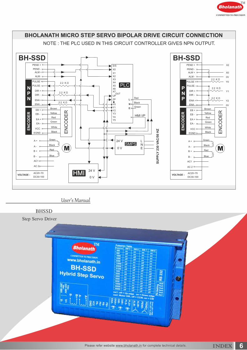
1. Drive Circuit Connection With BH-SDC-01 & 02 ( Step Servo )
INDEX
5
3
4
7
6
7
8
88910
11
12
12131415
15
151616
17
18
19
20
20
202020
6.3 Micro steps Setting6.2 Running Direction Setting6.1 Activate Edge Setting
6. DIP Switch Setting
7. Faults alarm and LED flicker frequency
8. Appearance and Installation Dimensions
9. Typical Connection
10. Processing Methods to Common Problems and Faults
10.1 Power on power light off10.2 Power on red alarm light on10.3 Red alarm light on after the motor running a small angle10.4 After input pulse signal but the motor not running
Overview ( Drive )
Drive circuit connection wth PLC And Drive front page
2.Features
3.Ports Introduction
3.1 ALM and PEND signal output ports3.2 Control Signal Input Ports3.3 Encoder Feedback Signal Input Ports3.4 Power Interface Ports
4. Technological Index
5. Connections to Control Signal
5.1 Connections to Common Anode5.2 Connections to Common Cathode5.3 Connections to Differential Signal5.4 Sequence Chart of Control Signals

BholanathTM
COMMITTED TO PRECISIONSTEP SERVO MOTORS
BHOLANATH STEP SERVO MOTORS
Bholanath Step Servo motors are closed loop stepping systems - high speed (>2000 RPM)stepper motors with incremental optical encoders and digital drives.
Incremental optical encoders ( 1000 PPR and 2500 PPR ) feedback with new generationdigital drives,Bholanath Step Servo motors get the reliability of servo motors.
Bholanath Step Servo motors are good replacement of servo motors (25 Watts to 1500 Watts),the price being much lower than servo motors.
Bholanath Step Servo motors give high speed performance of servo motors with accuratefeedback and micro stepping accuracy of stepper motors with feedback.
Bholanath Step Servo motors give better holding torque’s(complete stand still position).
As can seen from the graph,the Bholanath Step Servo motor torque equals servomotor torqueat 2000 RPM.Thus for applications up to 2000 RPM,Bholanath Step Servo motor can easily beused.At lesser RPM,say at 1000 RPM,the Bholanath Step Servo motor gives 50% more torquethan servo,giving the user much better performance.
The Step Servo Motor Driver has automatic current adjustments as per load,resultingin low heat / generation,thereby giving high efficiency.
Comparison between Bholanath Step Servo BHSS - 400 W with 400 Watt servo motor.
BHOLANATH STEP SERVO MOTOR BHSS - 400 W
SERVO MOTOR 400 WATTS
3INDEX
4

4INDEX
BholanathTM
COMMITTED TO PRECISION
BHSS - 400 W STEP SERVO MOTOR
BHOLANATH STEP SERVO MOTOR BHSS - 400 W
SERVO MOTOR 400 WATTS
TECHNICAL DATA
Power Input - BH-75Vac
Characteristics
Encoder Options - 1000 PPR/2500 PPR
Cable Length - 3 / 5 Meters
Motor - Bipolar Hybrid Stepper Motor
Step Angle - 1.8 Degree
Degree Of Protection - DIN 40050 IP 60 / IP 65
Insulation Class - H
Weight - 2.70 Kg
Current Per Phase - 4.0 A
Torque - 3.4 Nm - 1.27 Nm
RPM - 0 - 2000
Stock Temperature - ( - 10° C to + 70° C )
Operation Temperature - ( - 10° C to + 40° C )
Shaft Axial Play - 0.08 Max.Play (450 G Load)
Shaft Radial Play - 0.02 Max.Play (450 G Load)
Max. Radial Force - 220 N (20 MM from Front Flange)
Max. Axial Force - 60 N (20 MM from Front Flange)
Motor Options Available -Standard Model - SWith Low Backlash Planetary Gearbox - PLWith Electro Magnetic Brake - BRWith Spur Gearbox - SGCE Certificate - N - STANDARD/CE - CERTIFIED
BHSS- 400 W - S - 1000 - 3MTR.- IP 60-NORDERING CODE -
Closed Loop Stepping System which includes High Speed (>2000 RPM)Stepper Motors withIncremental Optical Encoders,Digital Drives and 3 Meter Cable.
SUITABILITY - The BHSS - 400 W Step Servo is comparable to 400 Watts Servo Motor upto 1500RPM.The Step - Servo Motor BHSS - 400 W gives more torque at lower RPM’s thus giving abetter performance than 400 Watts Servo Motors as seen in the graph.
TOR
QU
E (
Nm
)
4
0
0.5
1
1.5
2
2.5
3
1 30 60 90 210 270 300 400 500 700 900 1100 1300 1500 1700 1900 2000
RPM
5+0.0
30
0
-/+0.05
31.75±1
64.8±1 20
84.8
Ø73±0.0
5Ø
14-0
.012
25
2
9.6
69.6±0.2
86±0.5
86±0.5
69.6
±0.2
11.5
R7
7
3Meter
3MeterMotor
Encoder
Single Core x 0.34 sq mmMultistrand P.V.C Sheathed
Flexible wire
15
M5
4065
105
BholanathTM
COMMITTED TO PRECISION
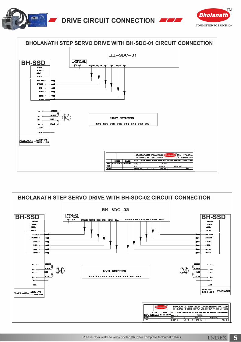
DRIVE CIRCUIT CONNECTION
5INDEX
1
1BHOLANATH STEP SERVO DRIVE WITH BH-SDC-01 CIRCUIT CONNECTION
BHOLANATH STEP SERVO DRIVE WITH BH-SDC-02 CIRCUIT CONNECTION
Bholanath
STEP SERVO MOTOR
BHSS-200W-HT
BHSSDStep Servo Driver
BholanathTM
COMMITTED TO PRECISION
User’s Manual
6INDEX
AC20~70
DC30-100
AC20~70
DC30-100
Blue
Black Black
Green Green
Blue

1. Overview
2. Features
The BHSSD hybrid stepper servo drive system integrates the servo control
technology into the digital stepper drive perfectly.And this product adopts an
optical encoder with high speed position sampling feedback of 50 µ s, once
the position deviation appears.it will be fixed immediately.This product is
compatible the advantages of the stepper drive and the servo drive , such
as lower heat , less vibration , fast acceleration and so on. This kind of servo
drive also has an excellent cost performance.
Without losting step, High accuracy in positioning.
100% rated output torque.
Variable current control technology, High current efficiency.
Small vibration, Smooth and reliable moving at low speed.
Compatible with 1000 and 2500 lines encoder.
No adjustment in general applications.
Over current, over voltage and over position error protection.
Green light means running while red light means protection or off line.
Accelerate and decelerate control inside, Great improvement in smoothnessof starting or stopping the motor.
Website : www.bholanath.in
7INDEX

3. Ports Introduction
3.1 ALM and PEND signal output ports
3.2 Control Signal Input Ports
Port Symbol Name Remark
1
2
3
4
PEND +
ALM +
ALM -
PEND -
In position signal output +
In position signal output -
Alarm output +
Alarm output -
+
-
1
2
3
4
1
2
3
4
5
6
Website : www.bholanath.in
8INDEX

Port Symbol Name Remark
1
2
3
5
4
6
PLS +
DIR +
ENA +
DIR -
ENA -
PLS -
Pulse signal +Compatible with
5V or 24 V
Compatible with5V or 24 V
Compatible with5V or 24 V
Pulse signal -
Direction signal +
Enable signal +
Direction signal -
Enable signal -
3.3 Encoder Feedback Signal Input Ports
1
2
3
4
5
6
Port Symbol Name Remark
1
2
3
5
4
EB + Brown
Yellow
Red
Green
White
Black
EA +
VCC
EA -
EB -
Encoder Phase B +
Encoder Phase B -
Encoder Phase A +
Input Power
Encoder Phase A -
6 GND Input power ground
Website : www.bholanath.in
9INDEX

Website : www.bholanath.in
3.4 Power Interface Ports
1
2
3
4
5
6
10INDEX
Port Identification Name Remark
1
2
3
5
4
6
Motor PhaseWire Input Ports
Power InputPorts
Phase A +(Green)Motor Phase A
Motor Phase B
AC 24 V - 70 VDC 30 V - 100 V
Phase A - ( Black )
Phase B + ( Red )
Input Power +
Phase B - ( Blue )
Input Power -
Symbol
A +
B +
B -
A -
VCC
GND
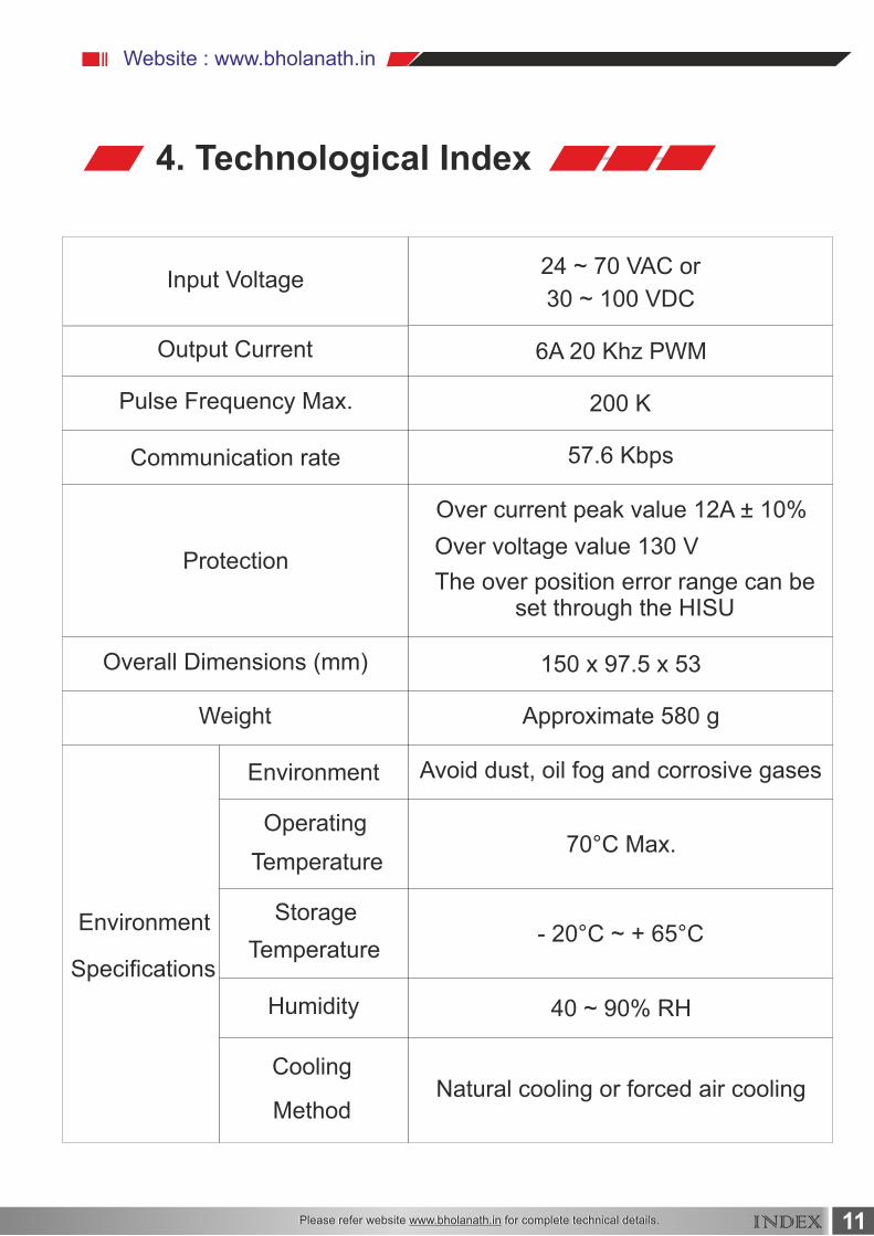
Input Voltage
Output Current
57.6 Kbps
200 K
6A 20 Khz PWM
Pulse Frequency Max.
Communication rate
Protection
Overall Dimensions (mm)
Weight
Environment
Specifications
Environment
Operating
Avoid dust, oil fog and corrosive gases
Approximate 580 g
150 x 97.5 x 53
The over position error range can beset through the HISU
Over voltage value 130 V
Over current peak value 12A ± 10%
Temperature
Temperature
Humidity 40 ~ 90% RH
Cooling
MethodNatural cooling or forced air cooling
Storage- 20°C ~ + 65°C
30 ~ 100 VDC
24 ~ 70 VAC or
70°C Max.
4. Technological Index
Website : www.bholanath.in
11INDEX

5. Connections to Control Signal
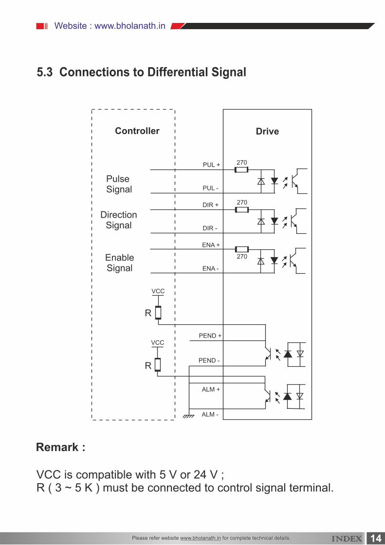
Remark :
VCC is compatible with 5 V or 24 V ;R ( 3 ~ 5 K ) must be connected to control signal terminal.
5.1 Connections to Common Anode
Website : www.bholanath.in
Controller Drive
PulseSignal
DirectionSignal
EnableSignal
VCC
VCC
VCC
ALM -
ALM +
PEND +
ENA -
ENA +
DIR +
DIR -
PUL -
PUL +
PEND -R
R
270
270
270
12INDEX

Remark :
VCC is compatible with 5 V or 24 V ;R ( 3 ~ 5 K ) must be connected to control signal terminal.
5.2 Connections to Common Cathode
Website : www.bholanath.in
Controller Drive
PulseSignal
DirectionSignal
EnableSignal
VCC
VCC
VCC
VCC
VCC
ALM -
ALM +
PEND +
ENA -
ENA +
DIR +
DIR -
PUL -
PUL +
PEND -R
R
270
270
270
13INDEX
Remark :
VCC is compatible with 5 V or 24 V ;R ( 3 ~ 5 K ) must be connected to control signal terminal.
5.3 Connections to Differential Signal
Website : www.bholanath.in
Controller Drive
PulseSignal
DirectionSignal
EnableSignal
VCC
VCC
ALM -
ALM +
PEND +
ENA -
ENA +
DIR +
DIR -
PUL -
PUL +
PEND -R
R
270
270
270
14INDEX
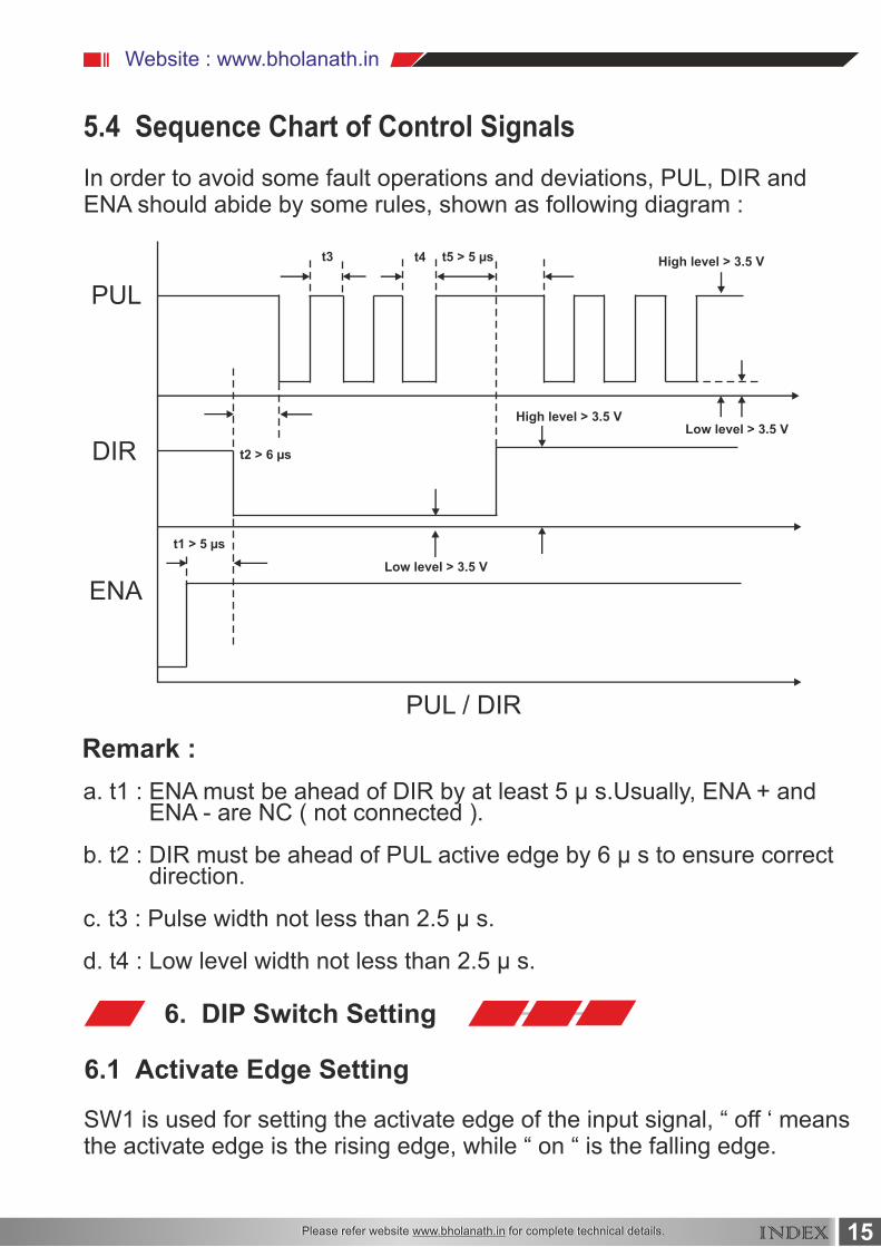
5.4 Sequence Chart of Control Signals
6. DIP Switch Setting
6.1 Activate Edge Setting
Website : www.bholanath.in
In order to avoid some fault operations and deviations, PUL, DIR andENA should abide by some rules, shown as following diagram :
SW1 is used for setting the activate edge of the input signal, “ off ‘ meansthe activate edge is the rising edge, while “ on “ is the falling edge.
a. t1 : ENA must be ahead of DIR by at least 5 µ s.Usually, ENA + and ENA - are NC ( not connected ).
b. t2 : DIR must be ahead of PUL active edge by 6 µ s to ensure correct direction.
c. t3 : Pulse width not less than 2.5 µ s.
d. t4 : Low level width not less than 2.5 µ s.
Remark :
PUL
DIR
PUL / DIR
t3 t4 t5 > 5 µs
t1 > 5 µs
t2 > 6 µs
ENA
High level > 3.5 V
High level > 3.5 VLow level > 3.5 V
Low level > 3.5 V
15INDEX
Website : www.bholanath.in
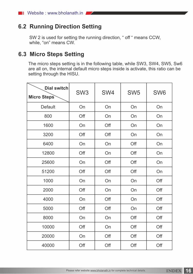
6.2 Running Direction Setting
6.3 Micro Steps Setting
SW 2 is used for setting the running direction, “ off “ means CCW, while, “on” means CW.
The micro steps setting is in the following table, while SW3, SW4, SW5, Sw6are all on, the internal default micro steps inside is activate, this ratio can besetting through the HISU.
Dial switch
Micro Steps
Default
800
1600
3200
6400
12800
25600
51200
1000
2000
4000
5000
8000
10000
20000
40000
Off
Off
Off
Off
Off
Off
Off
Off
Off
Off
Off
Off
Off
Off
Off
Off
Off
Off
Off
Off
Off
Off
Off
Off
Off
Off
Off
Off
Off
Off
Off
On
On
Off
On
On
On
On
On
On
On
On
On
On
On
On
On
On
On
On
On
On
On
On
On
On
On
On
On
On
On
On
On
On
SW3 SW4 SW5 SW6
16INDEX

Website : www.bholanath.in
7. Faults alarm and LED flicker frequency
0.8s
Red Alarm LED Flash Time Interval
2s
Flicker
FrequencyDescription to the Faults
Error occurs when the motor coil currentexceeds the drive’s current limit.
Voltage reference error in the drive.
Parameters upload error in the drive.
Error occurs when the input voltage exceeds thedrive’s voltage limit.
Error occurs when the actual position followingerror exceeds the limit which is set by the positionerror limit.
1
2
3
4
5
17INDEX

Website : www.bholanath.in
8. Appearance and Installation Dimensions
++
26.5
97.5
53
4.0
44
4 - Ø 4.0
Hybrid Step Servo Drive
142
142
150
18INDEX

Website : www.bholanath.in
9. Typical Connection This drive can provide the encoder with a power supply of +5V,
maximum current 80 mA.It adopts a quadruplicated-frequency counting
method, and the resoulation ratio of the encoder multiply 4 are the pulses
per rotate of the servo motor.Here is the typical connection of BHSSD.
19INDEX
Controller Drive
PulseSignal
DirectionSignal
EnableSignal
VCC
VCC
VCCALM -
ALM +
PEND +
ENA -
ENA +
DIR +
DIR -
PUL -
PUL +
R
R
270
270
270
EB +EB -EA +EA -VCC
GND
ENCODER
Brown
Yellow
Red
Green
White
M
VAC
24 ~ 70 V
Green
Black
Black
Blue
Red
A +
A -
B +
B -
AC 1
AC 2
Website : www.bholanath.in
10. Processing Methods to Common Problems and Faults
10.1 Power on power Light off
10.2 Power on red alarm light on
10.4 After input pulse signal but the motor not running
10.3 Red alarm light on after the motor running a small angle
No power input please check the power supply circuit.The voltage istoo low.
Please check the motor feedback signal and if the motor is connectedto the drive.
Please check the input pulse signal wires are connected in reliableway.
Please make sure the input pulse mode is corresponding with thereal input mode.
Please check the motor phase wires if they are connected correctly, ifnot, Please refer to the 3.4 Power Ports. Please check the parameter in the drive if the poles of the motor andthe encoder lines are corresponding with the real parameters, if not, setthem correctly. Please check if the frequency of the pulse signal is too fast, thus themotor may be out of the rated speed and lead to position error.
The stepper servo drive is over voltage or under voltage.Pleaselower or increase the input voltage.
20INDEX