Embed Size (px)
Citation preview

1
Training ReportIn
Control Equipment Engineering
Under the guidance of Submitted by:Mr. Dinesh Dubey Ronak Jain(Sr. Engg C.E.E.) Submitted to:

2
HRDC, BHEL Bhopal
Bharat Heavy Electricals LimitedBhopal
CERTIFICATE This is certified that Mr. Ronak Jain, student of Sardar Vallabhbhai National Institute of Technology, Surat has taken practical vocational training in Control Equipment Engineering at BHEL, Bhopal from 25.05.15 to 20.06.15. During the course of training, his interest & behavior was found to be satisfactory & dedicated to work.
Best wishes for his future

3
Date: 20.06.2015
Place: Bhopal Mr. Dinesh Dubey (Sr. Engg C.E.E.)
Declaration
I ,Ronak Jain ,student of Sardar Vallabhbhai National Institute of Technology hereby declare that I have successfully completed industrial training in Control Equipment Engineering.
The information incorporated in this report in true and original to the best of my knowledge.

4
Table of Contents
About BHEL Page 6
Operations Page 6
Main Manufacturing Facilities Page 7
Products and Services Page 8
Rail Transport in India Page 10

5
Locomotives Page 10EMU Page 10Types
Page 10
Locomotives Page 11
Steam Locomotives Page 11
Electronic Power for Locomotives Page 12
AC Locomotives with DC drive Page 13
Diode Page 14Thyristor Page 15DC Locomotive with DC drive
Page 17Dynamic Breaking
Page 19

6
AC Motor Page 19AC Locomotive with AC drive
Page 21IGBT Page 22Diesel Locomotives Page 23Diesel-Electric Types Page 25
EMU Page 26Car Types Page 26MEMU Page 27DEMU Page 27

7
About BHEL
Bharat Heavy Electricals Limited (BHEL), owned by Government of India, is a power plant equipment manufacturer and operates as an engineering and manufacturing company based in New Delhi, India. Established in 1964, BHEL is India's largest engineering and manufacturing company of its kind. The company has been earning profits continuously since 1971-72 and paying dividends uninterruptedly since 1976-77
Operations:

8
It is engaged in the design, engineering, manufacturing, construction, testing, commissioning and servicing of a wide range of products, systems and services for the core sectors of the economy, viz. Power, Transmission, Industry, Transportation, Renewable energy, Oil & Gas and Defence.It has a network of 17 manufacturing units, 2 repair units, 4 regional offices, 8 service centres, 8 overseas offices, 15 regional centres, 7 joint ventures, and infrastructure allowing it to execute more than 150 projects at sites across India and abroad. The company has established the capability to deliver 20,000 MW p.a. of power equipment to address the growing demand for power generation equipment.BHEL has retained its market leadership position during 2013-14 with 72% market share in the Power Sector. An improved focus on project execution enabled BHEL record its highest ever commissioning/synchronization of 13,452 MW of power plants in domestic and international markets in 2013-14, marking a 30% increase over 2012-13. The company has added more than 1,24,000 MW to the country's installed power generating capacity so far.It also has been exporting its power and industry segment products and services for over 40 years. BHEL's global references are spread across over 76 countries across all the six continents of the world.

9
The cumulative overseas installed capacity of BHEL manufactured power plants exceeds 9,000 MW across 21 countries. Their physical exports range from turnkey projects to after sales services.
Main manufacturing facilities
Centralized Stamping Unit & Fabrication Plant (CSU & FP), Jagdishpur
Insulator Plant (IP), Jagdishpur Electronics Division (EDN), Bangalore Industrial Systems Group (ISG), Bangalore Electro-Porcelains Division (EPD), Bangalore Heavy Electrical Plant (HEP), Bhopal Industrial Valves Plant (IVP), Goindwal Heavy Electrical Equipment Plant
(HEEP), Ranipur (Haridwar) Central Foundry Forge Plant (CFFP), Ranipur
(Haridwar) Heavy Power Equipment Plant
(HPEP), Hyderabad Transformer Plant (TP), Jhansi Boiler Auxiliaries Plant (BAP), Ranipet Component Fabrication Plant (CFP), Rudrapur High Pressure Boiler Plant (HPBP), Tiruchirappalli Seamless Steel Tube Plant (SSTP), Tiruchirappalli Power Plant Piping Unit (PPPU), Thirumayam Heavy Plates & Vessels Plant
(HPVP), Visakhapatnam

10
The company is also setting up a new Greenfield Power Equipment Fabrication Plant (GPEFP) at Bhandara, Maharashtra, the foundation stone for which was laid on 14 May 2013. Further, BHEL is planning to enter solar manufacturing in a big scale, as it has announced its plans for a 600 MW Solar Module Factory.[5]
Products and services[edit] Thermal power Plants [6]
Nuclear power Plants Gas based power Plants Hydro power Plants DG power Plants Boilers (steam generator) Boiler Auxiliaries Gas generator Hydro generator Steam turbine Gas turbine Hydro turbine Transformer Switchgear Oil field equipment Boiler drum Piping System Soot Blowers

11
Valves Seamless Steel Tubes Condenser s and Heat exchangers Pumps Desalination and Water treatment plants Automation and Control systems Power electronics Transmission system control Semiconductor devices Solar photo voltaics Software system solutions Bus ducts Insulators Control panels Capacitors Bushings Electrical machines DC, AC heavy duty Motors Compressors Control gears Traction motors Research and development products

12
Rail Transport in India
Locomotives: A locomotive or engine is a rail transport vehicle that provides the motive power for a train. A locomotive has no payload capacity of its own, and its sole purpose is to move the train along the tracks.
Electric Multiple Unit (EMU) : An electric multiple unit or EMU is a multiple unit train consisting of self-propelled carriages, using electricity as the motive power. An EMU requires no separate locomotive, as electric traction motors are incorporated within one or a number of the carriages.
Types of Locomotives: Steam Traction Diesel Traction DC Electric Traction AC Electric Traction

13
Types of EMU MEMU DEMU
LOCOMOTIVES
Steam Locomotive: A steam locomotive is a railway locomotive that produces its pulling power through a steam engine. These locomotives are fueled by burning combustible material—usually coal, wood, or oil—to produce steam in a boiler. The steam moves reciprocating pistons which are mechanically connected to the locomotive's main wheels (Drivers).

14
Both fuel and water supplies are carried with the locomotive, either on the locomotive itself or in wagons (tenders) pulled behind. The first steam locomotive was made by Richard Trevithick on the 21st of Feb 1804, two years after the railway locomotive he made in 1802 or the road locomotive he made in 1801.

15
ELECTRONIC POWER FOR LOCOMOTIVES
AC and DC Differences
To understand the principles of modern traction power control systems, it is worth a look at the basics of DC and AC circuitry. DC is direct current - it travels in one direction only along a conductor. AC is alternating current - so called because it changes direction, flowing first one way along the conductor, then the other. It does this very rapidly. The number of times it changes direction per second is called the frequency and is measured in Hertz (Hz). It used to be called cycles per second, in case you've read of this in historical papers. In a diagrammatic representation, the two types of current appear as shown in the diagram above.From a transmission point of view, AC is better than DC because it can be distributed at high voltages over a small size conductor wire, whereas

16
DC needs a large, heavy wire or, on many DC railways, an extra rail. DC also needs more frequent feeder substations than AC - the ratio for a railway averages at about 8 to 1. It varies widely from one application to another but this gives a rough idea. Over the hundred years or so since the introduction of electric traction on railways, the rule has generally been that AC is used for longer distances and main lines and DC for shorter, suburban or metro lines. DC gets up to 3000 volts, while AC uses 15,000 - 50,000 volts.Until recently, DC motors have been the preferred type for railways because their characteristics were just right for the job. They were easy to control too. For this reason, even trains powered from AC supplies were usually equipped with DC motors.
AC Locomotives with DC Drives

17
This diagram (above) shows a simplified schematic for a 25 kV AC electric locomotive used in the UK from the late 1960s. The 25 kV AC is collected by the pantograph and passed to the transformer. The transformer is needed to step down the voltage to a level which can be managed by the traction motors. The level of current applied to the motors is controlled by a "tap changer", which switches in more sections of the transformer to increase the voltage passing through to the motors. It works in the same way as the resistance controllers used in DC traction, where the resistance contactors are controlled by a camshaft operating under the driver's commands.
Before being passed to the motors, the AC has to be changed to DC by passing it through a rectifier. For the last 30 years, rectifiers have used diodes

18
and their derivatives, the continuing development of which has led to the present, state-of-the-art AC traction systems.
Diode
A diode is a device with no moving parts, known as a semi-conductor, which allows current to flow through it in one direction only. It will block any current which tries to flow in the opposite direction. Four diodes arranged in a bridge configuration, as shown below, use this property to convert AC into DC or to "rectify" it. It is called a "bridge rectifier". Diodes quickly became popular for railway applications because they represent a low maintenance option. They first appeared in the late 1960s when diode rectifiers were introduced on 25 kV AC electric locomotives.

19
Thyristor
The thyristor is a development of the diode. It acts like a diode in that it allows current to flow in only one direction but differs from the diode in that it will only permit the current to flow after it has been switched on or "gated". Once it has been gated and the current is flowing, the only way it can be turned off is to send current in the opposite direction. This cancels the original gating command. It's simple to achieve on an AC locomotive because the current switches its direction during each cycle. With this development, controllable rectifiers became possible and tap changers quickly became history.

20
A thyristor controlled version of the 25 kV AC electric locomotive traction system looks like the diagram here.
A tapping is taken off the transformer for each DC motor and each has its own controlling thyristors and diodes. The AC from the transformer is rectified to DC by chopping the cycles, so to speak, so that they appear in the raw as half cycles of AC as shown.
In reality, a smoothing circuit is added to remove most of the "ripple" and provide a more constant power flow as shown in the diagram. Meanwhile, the power level for the motor is controlled by varying the point in each rectified cycle at which the thyristors are fired. The later in the cycle the thyristor is gated, the lower the current available to the motor. As the gating is advanced, so the

21
amount of current increases until the thyristors are "on" for the full cycle. This form of control is known as "phase angle control".
SEPEXIn more recent thyristor control systems, the motors themselves are wired differently from the old standard DC arrangement. The armatures and fields are no longer wired in series, they are wired separately - separate excitement, or SEPEX. Each field has its own thyristor, which is used to control the individual fields more precisely.Since the motors are separately excited, the acceleration sequence is carried out in two stages. In the first stage, the armature is fed current by its thyristors until it reaches the full voltage. This might give about 25% of the locomotive's full speed. In the second stage, the field thyristors are used to weaken the field current, forcing the motor to speed up to compensate. This technique is known as field weakening and was already used in pre-electronic applications.A big advantage of SEPEX is that wheel slip can be detected and corrected quickly, instead of the traditional method of either letting the wheels spin until the driver noticed or using a wheel slip relay to switch off the circuit and then restart it.

22
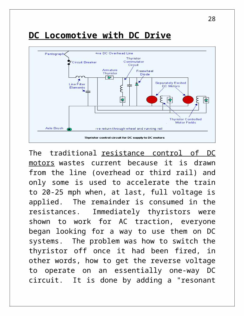
DC Locomotive with DC Drive
The traditional resistance control of DC motors wastes current because it is drawn from the line (overhead or third rail) and only some is used to accelerate the train to 20-25 mph when, at last, full voltage is applied. The remainder is consumed in the resistances. Immediately thyristors were shown to work for AC traction, everyone began looking for a way to use them on DC systems. The problem was how to switch the thyristor off once it had been fired, in other words, how to get the reverse voltage to operate on an essentially one-way DC circuit. It is done by adding a "resonant circuit" using an inductor and a capacitor to force current to flow in the opposite direction to normal. This has the effect of switching off the thyristor, or "commutating" it. It is shown as part of the

23
complete DC thyristor control circuit diagram. It has its own thyristor to switch it on when required.Two other features of the DC thyristor circuit are the "freewheel diode" and the "line filter". The freewheel diode keeps current circulating through the motor while the thyristor is off, using the motor's own electro magnetic inductance. Without the diode circuit, the current build up for the motor would be slower.Thyristor control can create a lot of electrical interference - with all that chopping, it's bound to. The "line filter" comprises a capacitor and an inductor and, as its name suggests, it is used to prevent interference from the train's power circuit getting into the supply system.
The thyristor in DC traction applications controls the current applied to the motor by chopping it into segments, small ones at the beginning of the acceleration process, gradually enlarging as speed increases. This chopping of the circuit gave rise to the nickname "chopper control". It is visually

24
represented by the diagram below, where the "ON" time of the thyristor is regulated to control the average voltage in the motor circuit. If the "ON" time is increased, so does the average voltage and the motor speeds up. The system began to appear on UK EMUs during the 1980s.
Dynamic BrakingTrains equipped with thyristor control can readily use dynamic braking, where the motors become generators and feed the resulting current into an on-board resistance (rheostatic braking) or back into the supply system (regenerative braking). The circuits are reconfigured, usually by a "motor/brake switch" operated by a command from the driver, to allow the thyristors to control the current flow as the motors slow down. An advantage of the thyristor control circuitry is its ability to choose either regenerative or rheostatic braking simply by automatically detecting the state of receptivity of the line. So, when the regenerated voltage across the supply connection filter circuit reaches a preset upper limit, a thyristor fires to divert the current to the on-board resistor.
The GTO ThyristorBy the late 1980s, the thyristor had been developed to a stage where it could be turned off by a control circuit as well as turned on by one.

25
This was the "gate turn off" or GTO thyristor. This meant that the thyristor commutating circuit could be eliminated for DC fed power circuits, a saving on several electronic devices for each circuit. Now thyristors could be turned on and off virtually at will and now a single thyristor could be used to control a DC motor.It is at this point that the conventional DC motor reached its ultimate state in the railway traction industry. Most systems now being built use AC motors.
AC MotorsThere are two types of AC motor, synchronous and asynchronous. The synchronous motor has its field coils mounted on the drive shaft and the armature coils in the housing, the inverse of normal practice. The synchronous motor has been used in electric traction - the most well-known application being by the French in their TGV Atlantique train. This used a 25 kV AC supply, rectified to DC and then inverted back to AC for supply to the motor. It was designed before the GTO thyristor had been sufficiently developed for railway use and it used simple thyristors. The advantage for the synchronous motor in this application is that the motor produces the reverse voltages needed to turn off the thyristors. It was a good solution is its day but it was quickly overtaken by the second type of AC motor - the

26
asynchronous motor - when GTO thyristors became available.The Asynchronous Motor
The asynchronous motor, also called the induction motor, is an AC motor which comprises a rotor and a stator like the DC motor, but the AC motor does not need current to flow through the armature. The current flowing in the field coils forces the rotor to turn. However, it does have to have a three phase supply, i.e. one where AC has three conductors, each conducting at a point one third into the normal cycle period, as visually represented in the diagram. The two big advantages of the 3-phase design are that, one, the motor has no brushes, since there is no electrical connection between the armature and the fields and, two, the armature can be made of steel laminations, instead of the large number of windings required in other motors. These features make it more robust and cheaper to build than a commutator motor.

27
AC Locomotive with AC DriveModern electronics has given us the AC drive. It has only become available with modern electronics because the speed of a 3-phase AC motor is determined by the frequency of its supply but, at the same time, the power has to be varied. The frequency used to be difficult to control and that is why, until the advent of modern electronics, AC motors were almost exclusively used in constant speed applications and were therefore unsuitable for railway operation. A modern railway 3-phase traction motor is controlled by feeding in three AC currents which interact to cause the machine to turn. The three phases are most easily provided by an inverter which supplies the three variable voltage, variable frequency (VVVF) motor inputs. The variations of the voltage and frequency are controlled electronically.
28
The AC motor can be used by either an AC or DC traction supply system. In the case of AC supply (diagram), the line voltage (say 25kV single phase) is fed into a transformer and a secondary winding is taken off for the rectifier which produces a DC output of say 1500 - 2000 volts depending on the application. This is then passed to the inverter which provides the controlled three phases to the traction motors. The connection between the rectifier and the inverter is called the DC link. This usually also supplies an output for the train's auxiliary circuits.All the thyristors are GTOs, including those in the rectifier, since they are now used to provide a more efficient output than is possible with the older thyristors. In addition, all the facilities of DC motor control are available, including dynamic braking, but are provided more efficiently and with less moving parts. Applied to a DC traction supply, the 3-phase set-up is even more simple, since it doesn't need a transformer or a rectifier. The DC line voltage is applied to the inverter, which provides the 3-phase motor control.Control of these systems is complex but it is all carried out by microprocessors. The control of the voltage pulses and the frequency has to be matched with the motor speed. The changes which occur during this process produce a set of characteristic buzzing noises which sound like the

29
"gear changing" of a road vehicle and which can clearly be heard when riding on the motor car of an AC driven EMU.
IGBTHaving got AC drive using GTO thyristors universally accepted (well, almost) as the modern traction system to have, power electronics engineers have produced a new development. This is the IGBT or Insulated Gate Bipolar Transistor. The transistor was the forerunner of modern electronics, (remember transistor radios?) and it could be turned on or off like a thyristor but it doesn't need the high currents of the thyristor turn off. However it was, until very recently, only capable of handling very small currents measured in thousanths of amps. Now, the modern device, in the form of the IGBT, can handle thousands of amps and it has appeared in traction applications. A lower current version was first used instead of thyristors in auxiliary supply inverters in the early 1990s but a higher rated version has now entered service in the most recent AC traction drives. Its principle benefit is that it can switch a lot faster (three to four times faster) than GTOs. This reduces the current required and therefore the heat generated, giving smaller and lighter units. The faster switching also reduces the complex "gearing" of GTOs and makes for a much smoother and more even sounding acceleration buzz from

30
under the train. With IGBTs, "gear changing" has gone.
Diesel LocomotivesThe modern diesel locomotive is a self contained version of the electric locomotive. Like the electric locomotive, it has electric drive, in the form of traction motors driving the axles and controlled with electronic controls. It also has many of the same auxiliary systems for cooling, lighting, heating, braking and hotel power (if required) for the train. It can operate over the same routes (usually) and can be operated by the same drivers. It differs principally in that it carries its own generating station around with it, instead of being connected to a remote generating station through overhead wires or a third rail. The generating station consists of a large diesel engine coupled to an alternator producing the necessary electricity. A fuel tank is also essential. It is interesting to note that the modern diesel locomotive produces about 35% of the power of a electric locomotive of similar weight.

31
Parts of a Diesel-Electric Locomotive
Diesel EngineThis is the main power source for the locomotive. It comprises a large cylinder block, with the cylinders arranged in a straight line or in a V (see more here). The engine rotates the drive shaft at up to 1,000 rpm and this drives the various items needed to power the locomotive. As the transmission is electric, the engine is used as the power source for the electricity generator or alternator, as it is called nowadays.
Main AlternatorThe diesel engine drives the main alternator which provides the power to move the train. The alternator generates AC electricity which is used to provide power for the traction motors mounted on the trucks (bogies). In older locomotives, the alternator was a DC machine, called a generator. It produced direct current which was used to provide power for DC traction motors. Many of

32
these machines are still in regular use. The next development was the replacement of the generator by the alternator but still using DC traction motors. The AC output is rectified to give the DC required for the motors.
Auxiliary AlternatorLocomotives used to operate passenger trains are equipped with an auxiliary alternator. This provides AC power for lighting, heating, air conditioning, dining facilities etc. on the train. The output is transmitted along the train through an auxiliary power line. In the US, it is known as "head end power" or "hotel power". In the UK, air conditioned passenger coaches get what is called electric train supply (ETS) from the auxiliary alternator.
Rectifiers/InvertersThe output from the main alternator is AC but it can be used in a locomotive with either DC or AC traction motors. DC motors were the traditional type used for many years but, in the last 10 years, AC motors have become standard for new locomotives. They are cheaper to build and cost less to maintain and, with electronic management can be very finely controlled. To convert the AC output from the main alternator to DC, rectifiers are required. If the motors are DC, the output from the rectifiers is used directly. If

33
the motors are AC, the DC output from the rectifiers is converted to 3-phase AC for the traction motors.
Diesel-Electric TypesDiesel-electric locomotives come in three varieties, according to the period in which they were designed. These three are:DC-DC (DC generator supplying DC traction motors);AC-DC (AC alternator output rectified to supply DC motors) and AC-DC-AC (AC alternator output rectified to DC and then inverted to 3-phase AC for the traction motors).
The DC - DC type has a generator supplying the DC traction motors through a resistance control system, the AC - DC type has an alternator producing AC current which is rectified to DC and then supplied to the DC traction motors and, finally, the most modern has the AC alternator output being rectified to DC and then converted to AC (3-phase) so that it can power the 3-phase AC traction motors. Although this last system might seem the most complex, the gains from using AC motors far outweigh the apparent complexity of the system.

34
EMU Car Types
The cars that form a complete EMU set can usually be separated by function into four types: power car, motor car, driving car, and trailer car. Each car can have more than one function, such as a motor-driving car or power-driving car. A power car carries the necessary equipment to
draw power from the electrified infrastructure, such as pickup shoes for third rail systems and pantographs for over head systems, and transformers.

35
Motor cars carry the traction motors to move the train, and are often combined with the power car to avoid high-voltage inter-car connections.
Driving cars are similar to a cab car, containing a driver's cab for controlling the train. An EMU will usually have two driving cars at its outer ends.
Trailer cars are any cars that carry little or no traction or power related equipment, and are similar to passenger cars in a locomotive-hauled train. On third rail systems the outer vehicles usually carry the pick up shoes, with the motor vehicles receiving the current via intra-unit connections.
MEMUThe Mainline Electric Multiple Unit or MEMU is a commuter rail system in India operated by the Indian Railway for semi-urban and rural areas. The system uses Mainline Electrical Multiple Units (MEMU) operating on Alternating Current (AC) drawn from over-head cables through the catenary system.
DEMUIn a diesel-electric multiple unit (DEMU) a diesel engine drives an electrical generator or an alternator which produces electrical energy. The generated current is then fed to electric traction

36
motors on the wheels or bogies in the same way as a conventional diesel electric locomotive. In modern DEMUs, such as the Bombardier Voyager family, each car is entirely self-contained and has its own engine, generator and electric motors.