Embed Size (px)
Citation preview

BGP in Large NetworksScaling BGP across multiple locations
www.noction.com

Page 1 of 15
BGP in Large Networks
Table of Contents
Introduction..................................................................................................................................2iBGP with loopback addresses........................................................................................................3Propagating loopback and next hop addresses.............................................................................5Route reflectors....................................................................................................................................7Where to originate prefixes..............................................................................................................9Filtering announcements...............................................................................................................12Conclusion.....................................................................................................................................15

Page 2 of 15
However, things do get more complex in networks that span mul-tiple locations and have routers that communicate with other net-works over eBGP in more than one location. In those networks, it’s important to think about the following:
Using iBGP with loopback addressesMaking sure all routers know next hop and loopback addressesWhether to use route reflectors rather than an iBGP full meshWhere to originate prefixesWhere and how to filter announcements
Implementing BGP has many benefits: it becomes possible to use multiple ISPs at the same time, augment transit service from an ISP with peering with other networks and isolation from problems in ISP networks. If, when using multiple ISPs, one ISP goes down, most of the time BGP automatically re-routes traffic over the other ISP(s). And if an ISP doesn’t de-liver the desired performance, connecting to another one is just a matter of getting the physical connection in place and a few lines in a router configuration—no renumbering of serv-ers and other systems necessary.
Usually, when an organization implements BGP for the first time, they do this by putting two BGP routers at the edge of their network. Of course just one BGP router would also work, but the second one is required in case the first one fails. The existing internal network is usually left running as before, typ-ically using OSPF routing. This makes for a very simple BGP setup, where each router has the requisite filters to make sure only the network’s own IP address block(s) are advertised to the outside world over eBGP (external BGP), an all of one iBGP (internal BGP) session between the two BGP routers. Adding a third and maybe even a fourth router in the same location doesn’t change that picture very much.
BGP in Large Networks
Introduction

Page 3 of 15
When a network only has two BGP routers and those routers are connected using a connection that is very unlikely to go down, the most straightforward iBGP setup is to simply configure it much the same as an eBGP session: by using the interface address of the other router as the neighbor address, as displayed in Figure 1.
However, in a larger network the BGP routers typically don’t sit right next to each other so it can simply be assumed that the link between them never goes down. Suppose that in the network in Figure 2 the link between routers 1 and 3 goes down. This means that address 10.0.1.1 on router 1 and address 10.0.1.2 on router 3 are no longer reachable, so all iBGP sessions to and from those addresses go down, even though routers 1 and 3 can still commu-nicate by going through routers 2 and 4.
Figure 1: an iBGP session using interface addresses in a small network
Figure 2: iBGP sessions using interface addresses in a larger network
BGP in Large Networks
iBGP with loopback addresses

Page 4 of 15
By using loopback addresses as the source and destination of iBGP sessions, there is no longer any dependency on a particular interface of a router. This may seem strange, as hosts always use the loopback addresses 127.0.0.1 (IPv4) and ::1 (IPv6). On a host, the loopback ad-dress is used for applications to talk to other applications running on the local system. However, on routers, loopback interfaces have a regular address, which can be used for management and control communication.
The difference between a loopback address and the address config-ured on a regular interface is that the loopback address is always up, while an interface address becomes unreachable when the interface it’s configured on goes down. Because loopback interfaces don’t con-nect to anything, it’s possible to configure them with an individual /32 (IPv4) or /128 (IPv6) address. However, in order for remote systems to reach a loopback address, it must be injected into an interior routing protocol such as OSPF.
So in Figure 3, if the link between routers 1 and 3 goes down, the iBGP session (and all data packets between routers 1 and 3) will flow through routers 2 and 4. When the link between routers 1 and 3 comes back up and then the link between routers 2 and 4 goes down, the iBGP packets as well as data packets between routers 1 and 3 fill flow over the direct link, and now the communication between routers 2 and 4 will also make use of that path.
BGP in Large Networks
Figure 3: iBGP sessions using loopback addresses

Page 5 of 15
BGP in Large Networks
On a Cisco router, the configuration to use iBGP between loopback addresses would look like this:
The loopback interface gets IP address 192.0.2.1/32. The peer-group ibgp is configured to use the same AS number for the re-mote routers as the local AS number; this makes the BGP sessions in question iBGP sessions. The update-source line makes sure the router will use the address of the loopback interface as the source address in outgoing BGP updates. Three neighbors inherit the settings configured for the peergroup ibgp.
The configuration above needs one additional thing: other routers in the network need to know where to send their packets for each router’s loopback address in order to set up their iBGP sessions. This is accomplished by running an internal routing protocol such as OSPF and then redistributing those loopback addresses into that routing protocol.
eBGP, on the other hand, normally runs between addresses on opposite sides of a shared subnet, and as such each router knows where to send packets addressed to the other by virtue of being connected to that same subnet. However, there is a complication: when a prefix learned over eBGP is propagated over iBGP, its next hop address isn’t changed.
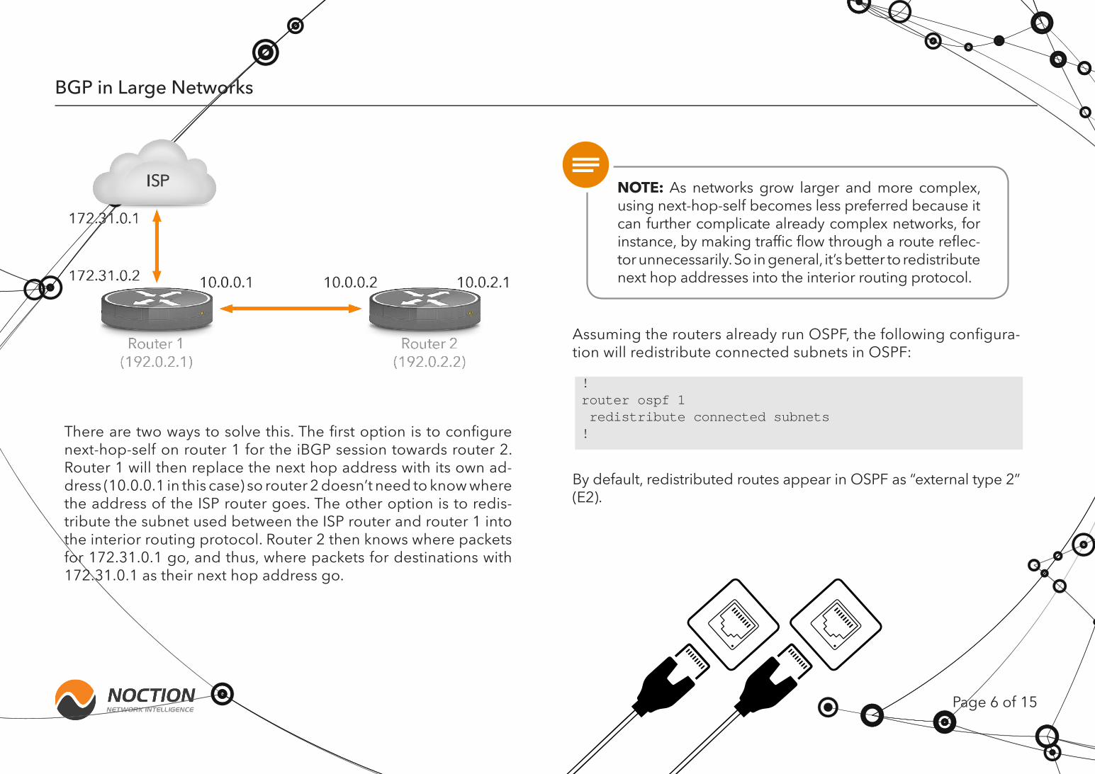
For instance, consider Figure 4. Router 1 and the ISP router share the 172.31.0.x subnet, so router 1 can reach the ISP router’s ad-dress 172.31.0.1 without the help from an interior routing proto-col. The prefixes router 1 receives from the ISP router then have 172.31.0.1 as their next hop address, which obviously doesn’t pose any issues for router 1. However, when router 1 propagates these prefixes to router 2 over iBGP, they’ll still have next hop address 172.31.0.1, and router 2 doesn’t have a route to that address.
!interface Loopback0 ip address 192.0.2.1 255.255.255.255!router bgp 65000 neighbor ibgp peer-group neighbor ibgp remote-as 65000 neighbor ibgp update-source Loopback0 neighbor 192.0.2.2 peer-group ibgp neighbor 192.0.2.3 peer-group ibgp neighbor 192.0.2.4 peer-group ibgp!
Propagating Loopback and Next Hop Addresses
Page 6 of 15
BGP in Large Networks
There are two ways to solve this. The first option is to configure next-hop-self on router 1 for the iBGP session towards router 2. Router 1 will then replace the next hop address with its own ad-dress (10.0.0.1 in this case) so router 2 doesn’t need to know where the address of the ISP router goes. The other option is to redis-tribute the subnet used between the ISP router and router 1 into the interior routing protocol. Router 2 then knows where packets for 172.31.0.1 go, and thus, where packets for destinations with 172.31.0.1 as their next hop address go.
Assuming the routers already run OSPF, the following configura-tion will redistribute connected subnets in OSPF:
By default, redistributed routes appear in OSPF as “external type 2” (E2).
NOTE: As networks grow larger and more complex, using next-hop-self becomes less preferred because it can further complicate already complex networks, for instance, by making traffic flow through a route reflec-tor unnecessarily. So in general, it’s better to redistribute next hop addresses into the interior routing protocol.
!router ospf 1 redistribute connected subnets!

Page 7 of 15
BGP in Large Networks
To avoid loops, BGP routers are only allowed to learn prefixes over iBGP from the router that advertises them or learned them over eBGP. As a result, every BGP router must have an iBGP session with every other BGP router in the network. In other words: there must be a full mesh of iBGP sessions. In networks with hundreds of routers, maintaining so many iBGP sessions can become a prob-lem. However, long before the router’s CPUs get overloaded with iBGP processing, the iBGP full mesh requirement becomes prob-lematic when adding new routers, as this requires configuring all existing routers with a new iBGP session.
There are two ways to avoid the iBGP full mesh requirement: con-federations and route reflectors. Confederations split an Autono-mous System (AS) into sub-ASes where the full mesh requirement only applies within each sub-AS. However, confederations have fallen out of use. Route reflectors propagate information learned over one iBGP session over other iBGP sessions, implementing additional logic to make sure there can’t be any loops. In a net-work with route reflectors, there are three types of BGP routers:
Route reflectorsRoute reflector clientsNon-client peers
To further complicate matters, there can be a hierarchy of route re-flectors, where a route reflector is in turn a client of another route reflector. However, the configuration is very straightforward:
In this configuration, neighbors 192.0.2.2 and 192.0.2.3 are mem-bers of the rrclients peergroup, and thus the route-reflector-client statement applies to them, making them route reflector clients. Neighbor 192.0.2.4 and 192.0.2.5 are in the regular ibgp peer-group and are not route reflector clients. They may be route reflec-tor themselves, or they can be non-client peers.
Route Reflectors
!router bgp 65000 neighbor ibgp peer-group neighbor ibgp remote-as 65000 neighbor ibgp update-source Loopback0 neighbor rrclients peer-group neighbor rrclients remote-as 65000 neighbor rrclients update-source Loopback0 neighbor rrclients route-reflector-client neighbor 192.0.2.2 peer-group rrclients neighbor 192.0.2.3 peer-group rrclients neighbor 192.0.2.4 peer-group ibgp neighbor 192.0.2.5 peer-group ibgp!

Page 8 of 15
BGP in Large Networks
NOTE: The route-reflector-client keyword on an iBGP session makes the router on the other end of that iBGP session a route reflector client. The client itself doesn’t know that it’s a route reflector client and doesn’t change its behavior.
NOTE: As such, it’s best to have at least one route re-flector be local to the route reflector clients and/or have route reflectors in all locations that have external con-nectivity.
In this setup, the iBGP full mesh requirement still applies to non-clients 192.0.2.4 and 192.0.2.5, so these still need to have an iBGP session towards each other. The route reflector will propagate iBGP information from the other iBGP routers to 192.0.2.2 and 192.0.2.3, so these routers don’t require iBGP sessions with any other BGP routers. However, it’s fine for these routers to have additional iBGP sessions, it’s just that they don’t need to have iBGP sessions to the rest of the BGP routers anymore. In practice, each BGP router should be served by at least two route servers, so when something goes wrong with one route server, the clients don’t get disconnected from the iBGP cloud.
It’s important to give some consideration to the placement of route reflectors. Suppose that in the network in Figure 3 routers 1 and 2 are route reflectors. Router 3 now wants to send packets to a desti-nation that is reachable over eBGP through both router 1 and router 4. Router 4 is in the same location as router 3, so under normal cir-cumstances, the shorter internal path towards router 4 would make the path through router 4 more preferred, assuming that the local
preference, AS path length and MED are all the same. However, to router 1, its own external path is preferred over the path through router 4. So in its capacity as a route reflector, router 1 will propa-gate its own external path to router 3, effectively hiding the path through router 4. And as a result the packets will travel a longer path across the internal network than would be the case without route reflectors or the case where router 3 has an iBGP session to a local route reflector.
Page 9 of 15
BGP in Large Networks
But now the connection between locations A and B goes down. This means that when a packet arrives at router 1 or router 2 to an address in 10.0.66.0/23, that packet can’t be delivered to its destination. The same for when a packet to an address in 10.0.64.0/23 that arrives at routers 3 or 4.
One solution is to have the addresses used in location A origi-nated in BGP by routers in location A and addresses used in lo-cation B by routers in location B. So routers 1 and 2 would origi-nate 10.0.64.0/23 while routers 3 and 4 originate 10.0.66.0/23. Under normal circumstances the announcements will propagate over iBGP so all routers announce both prefixes. The difference is that when the connection between the two locations goes down, the 10.0.64.0/23 prefix doesn’t reach routers 3 and 4 so those stop announcing it to their eBGP neighbors and 10.0.66.0/23 doesn’t reach routers 1 and 2 and thus their eBGP neighbors. As a result, packets won’t end up in the wrong locations so each location can still independently connect to destinations across the internet.
With one exception: even though both locations are connected to the internet, they won’t be able to talk to each other. The rea-son for this is that when both locations use the same AS number, routers 1 and 2 will see their own AS number for the 10.0.66.0/23 prefix advertised by routers 3 and 4 when it arrives over eBGP, which makes BGP think there’s a routing loop. So to avoid prob-
In a network with just two BGP routers, both BGP routers an-nounce all prefixes. They also originate all prefixes. To originate a prefix means that a BGP router is configured to inject a prefix into BGP. It will then announce that prefix over all its iBGP ses-sions. On its eBGP sessions, a router will advertise/announce all of the network’s prefixes (assuming no filters are in place to pre-vent this). It doesn’t matter whether those prefixes are originat-ed by the router itself, or the prefixes are originated by anoth-er router and propagated to other routers in the AS over iBGP. Originating prefixes is typically done using network statements with a little help from a null0 route:
NOTE: A Cisco router won’t originate a route unless that route is present in its routing table. A static route point-ing to the null0 interface accomplishes this.
Where to Originate Prefixes
!router bgp 65000 network 10.0.64.0 mask 255.255.252.0!ip route 10.0.64.0 255.255.252.0 null0!

Page 10 of 15
BGP in Large Networks
One way to solve this is with a default route. Or by static routes to-wards one or more ISPs for the prefixes used in the other location. However, in this case the static route must have a higher adminis-trative distance than that of BGP, or the static routes will overrule the BGP routes when the connection between both locations is up.
The administrative distance is a value that allows a router to select a route when the same prefix is present in more than one routing protocol. By default, OSPF has a distance of 110. Routes learned over eBGP have a distance of 20, lower than that of (nearly) all other routing protocols, while routes learned over iBGP have a distance of 200, higher than all other routing protocols. So a good distance value for a floating static route (one that normally isn’t used but becomes active when other routes disappear) would be 250, and is configured as follows:
Another way to solve this problem is with a tunnel such as a GRE (generic routing encapsulation) tunnel or a VPN tunnel between both locations. Of course in that case it’s important to use ad-dresses for the tunnel endpoints that are always reachable, i.e.,
Selectively advertising prefixes in each location is also predicat-ed on the assumption that it’s possible to group the addresses in each location into a number of prefixes that can be indepen-dently advertised in BGP. If the network only has a single /24, this won’t be possible as a /24 is the smallest block that is generally accepted in BGP. Or maybe the second location only uses a /26. It’s also possible for subnets to span multiple locations. In these situations, BGP can’t help keep things running when the link be-tween locations goes down. Or perhaps the added complexity required to allow BGP to do this isn’t considered worth it.
Obviously, it’s helpful to make the connection between locations as robust as possible, perhaps using two independently routed connections. With that in place, it can be a reasonable choice to only announce prefixes in the most important location so the secondary location becomes unreachable when the link between locations goes down—even though the secondary location may still have BGP sessions with one or more ISPs. But because the network’s prefix or prefixes are injected in BGP in the other lo-cation and the iBGP sessions are down, the BGP routers in the secondary location simply have nothing to announce and thus won’t receive any incoming traffic.
!ip route 10.0.64.0 255.255.254.0 172.20.0.1 250!
not the network’s own 10.0.64.0/22 prefix in our example. A com-plication with tunnels is that they reduce the maximum packet size. In theory, path MTU discovery (PMTUD) should automati-cally reduce packet sizes, but in practice this often leads to com-plications.
lems, BGP ignores all prefixes learned over eBGP with the local AS number in the AS path.

Page 12 of 15
BGP in Large Networks
Another possibility is the situation shown in Figure 5, where a net-work has its infrastructure in location C where there aren’t any eBGP connections available, and then uses internal links to two or more satellite locations where it connects to external networks. In this case, it’s best to have two BGP routers that originate the network’s prefixes in location C, even though there are no connections to ex-ternal networks in location C. These BGP routers can be relatively modest, as they don’t necessarily need to handle any traffic if other
devices, perhaps switches and/or firewalls, already handle that. Their sole purpose is to handle the BGP announcements.
The reason to have routers 3 and 4 originate the prefixes is that when the link to location A goes down but router 1 is still connected to external networks, router 1 will automatically stop announcing the network’s prefixes and traffic will start flowing through location B because router 2 still receives the announcements over iBGP from routers 3 and 4 and propagates them over eBGP. The same when the link to location B is down but the link to location A is up.
When peering over an Internet Exchange, it’s common to have one or more routers that just handle Internet Exchange peering while other routers handle connections to one or more ISPs for the traffic that can’t be exchanged over peering. In those cases, the Internet Exchange routers should never originate any prefixes. In general, when a location only has one or more routers for the purpose of connecting to the outside world, without any servers or users or anything else connected, then prefixes shouldn’t be originated from that location.
In the simple two-router BGP setup, filtering announcements is very straightforward: each router is configured with the required filters. It’s recommended to have two filters, one that only allows the network’s own prefixes in outgoing eBGP updates, and one that only allows AS paths with just the network’s AS number:
Filtering Announcements
Figure 5: Main location C with satellite locations A and B for handling eBGP
Page 12 of 15
BGP in Large Networks
In this example, AS path access list 2 only permits empty AS paths. All prefixes received over eBGP have an AS path one or more ASes in it, so those prefixes aren’t allowed in outgoing updates. Prefixes originated in the local AS have an empty AS path at the time the filter is applied, the local AS number is added to the AS path between the moment the filter is applied and the moment the update is transmitted over eBGP. The prefix list named export only allows the locally originated /22.
Both the AS path filter list and the prefix list specify what’s allowed and then end, depending on the “implicit deny” property of Cisco access lists: everything that is not explicitly allowed by an access list is denied.
Having both access lists in place provides protection against the situation where one of the filters doesn’t function properly.
This way, it’s possible to update a filter by pasting a new one to the router’s command line as follows:
With two filters present, the AS path access list still makes sure no improper updates leak out to the rest of the world while the modified prefix list is being pasted into the configuration. And yes, without a second filter, that does happen. If the BGP neigh-bor has a prefix limit applied to the session, the updates that slip through can easily be enough to trigger the maximum prefix limit so it’s necessary to ask the other side to clear the session manu-ally. So when only a single filter is present, be sure to use a more conservative way to modify filters; i.e., by adding/removing indi-vidual lines rather than replacing the entire filter.
!router bgp 65000 network 10.0.64.0 mask 255.255.252.0 neighbor 172.19.0.1 remote-as 65065 neighbor 172.19.0.1 filter-list 2 out neighbor 172.19.0.1 prefix-list export out!ip as-path access-list 2 permit ^$!ip prefix-list export permit 10.0.64.0/22!ip route 10.0.64.0 255.255.252.0 null0!
!no ip prefix-list exportip prefix-list export permit 10.0.64.0/22ip prefix-list export permit 10.0.64.0/23ip prefix-list export permit 10.0.66.0/23!
NOTE: During the moment or two that the export prefix list isn’t present (even though it’s referenced in the BGP section of the configuration), all updates are allowed through.

Page 13 of 15
BGP in Large Networks
However, in larger networks having an outgoing AS path ac-cess list as well as an outgoing prefix list comes problematic. In really large networks, those filters may become unmanageably large. But even in medium-sized networks, having to reconfig-ure all routers when a new prefix gets added quickly becomes problematic. This is especially true in ISP networks where new customers often bring new prefixes and new ASes that should be allowed by the filters.
An alternative to enumerating all ASes and prefixes that are allowed is to tag all prefixes that should be advertised with a community and then filter on that community on outgoing eBGP sessions. This is a little more complex initially, but the big advantage is that it’s only necessary to filter prefixes on the routers where they’re originated or are learned over eBGP. This means the configurations of all other routers remain un-changed when a new prefix is added.
This is the configuration for a router that originates a prefix:
Because typically, ISPs don’t do much filtering on the peering sessions between them, it’s of paramount importance for ISPs to make sure they only allow legitimate advertisements from their customers. So here, once again two filters are used: an AS path filter list and a prefix list make sure only the prefixes that belong to the customer are accepted. The AS path filter list uses a regular expression that matches the beginning of the AS path (the ^ character) followed by the customer’s AS number a space: 64999_. That sequence is put between parentheses so the + character applies to the entire sequence, allowing it to be present one or more times. Then the $ character marks the end of the AS path, so there is no room for any other AS num-bers. In other words: the customer may announce prefixes with an AS path that contains the customer’s own AS number one or more times, but no other AS numbers.
The prefix list allows two prefixes. If a prefix is allowed by both the AS path filter and the prefix list, the route map custa-in is ap-plied, which applies the community 65000:2 to the prefix. The additive keyword preserves the community values that were al-ready present. The route map also sets the local preference to 200, so routes received directly from the customer are always preferred over the same prefixes learned from other ISPs.
At this point, the BGP table holds prefixes with community 65000:1 that are originated within the network itself and prefix-es with community 65000:2 that were learned from customers. The following configuration allows these prefixes to be adver-tised to external (non-customer) networks.
!router bgp 65000 network 10.0.64.0 mask 255.255.252.0 route-map set-self!ip route 10.0.64.0 255.255.252.0 null0!route-map set-self permit 10 set community 65000:1!

Page 14 of 15
BGP in Large Networks
This configuration is the same on all the network’s routers, wheth-er those routers originate prefixes or learn prefixes from custom-ers or not.!router bgp 65000 neighbor 172.19.0.1 remote-as 65065 neighbor 172.19.0.1 route-map strip-comm in neighbor 172.19.0.1 route-map allow-out out!ip community-list standard del-comm permit 65000:1ip community-list standard del-comm permit 65000:2!ip community-list standard allowed-out-deny deny 65000:1ip community-list standard allowed-out-deny deny 65000:2ip community-list standard allowed-out-deny permit!route-map strip-comm permit 10 set comm-list del-comm delete!route-map allow-out deny 10 match community allowed-out-deny!route-map allow-out permit 20 set comm-list del-comm delete!
The incoming one is simple enough: it uses the community list fil-ter “del-comm” to match the communities 65000:1 and 65000:2 that are used to tag the network’s own and the network’s cus-tomer routes. If those communities are present, they’re removed from the prefixes received from AS 65065. This way, nothing un-expected happens should those communities be applied else-where by accident or maliciously.
The route map allow-out is a bit more unusual, as it uses deny 10 for the first clause rather than the expected permit 10. The match then points towards the allowed-out-deny community list. There, things get a bit tricky, because here the communi-ties that should actually be allowed are denied, while all pre-fixes that don’t have either of these communities on them are permitted. But because this is a deny route map clause, the pre-fixes matched in the match section are actually denied and fil-tered out. The prefixes denied in the community list have now encountered a double negative and are therefore permitted to progress further.
Of course the same effect could have been achieved with a reg-ular permit route map and a deny community filter... Except that in that case, a match would simply have allowed the prefixes to be advertised—with no opportunity to apply any further route map actions. In this example, the prefixes that survive the deny 10 clause (because they have the 65000:1 or 65000:2 com-munity) go on to the permit 20 clause. There, the 65000:1 and 65000:2 communities are removed because the rest of the in-ternet doesn’t have any use for them. At this point, it’s also pos-
In this configuration, the BGP session with AS 65065 is configured with two route maps: one that is applied to incoming updates and one that is applied to outgoing updates.

Page 15 of 15
BGP in Large Networks
!ip prefix-list import deny 10.0.64.0/22 le 32ip prefix-list import permit 0.0.0.0/0 le 24!
sible to apply additional actions, such as setting the Multi Exit Discriminator or performing AS path prepending.
Note that the above only applies to outgoing filters on BGP ses-sions to other networks. There are also two other types of filters that are important: incoming filters on BGP sessions and outgo-ing filters on router interfaces.
Although ISPs advertise connectivity to the entire world in BGP, there are two types of prefixes that are best filtered out from ISPs and peering partners: the network’s own prefixes and internet exchange prefixes. By accepting more specific routes towards its own address space, a network may be tricked into sending traffic for internal destinations towards an external network. And accepting more specific routes for an internet exchange peer-ing LAN leaves a network vulnerable to mistakes that may take down its peering sessions. As such, it’s best to filter out these prefixes and all more specific sub-prefixes:
This filter filters out the 10.0.64.0/22 prefix as well as all longer (more specific) prefixes that fall within that /22, such as 10.0.64.0/23, 10.0.66.0/23, 10.0.64.0/24, 10.0.65.0/24 and so on. It then permits all prefixes as long as the prefix length is at least (le = less or equal) 24 bits.
On the interfaces that connect to ISPs and peering partners, it’s best practice to only allow outgoing packets with source address-es that belong to the network. So if a computer connected to the network sends out packets with spoofed source addresses, those packets aren’t propagated to the rest of the internet. (See BCP 38.) However, these anti-spoofing filters don’t have to be applied at the edge of the network. They can also be applied on the inter-faces that receive packets from servers or users.
NOTE: Сustomer prefixes should not be filtered in this manner. If the connection to a customer goes down, the customer’s prefixes may legitimately arrive through one of the customer’s other ISPs.
So it’s still a good idea to have a filter like this on all non-customer eBGP sessions, which means that all routers must be reconfigured when new prefixes are added to the network. However, this doesn’t have to happen immediately: everything still works without updating this filter, it’s just that the protection against one (rare) type of attack isn’t in place yet.
As BGP networks grow, they inevitably get more complex. But with some careful planning, it’s possible keep a larger BGP network functioning in a straightforward manner so unnecessary extra work and mistakes can be minimized.
Conclusion

Copyright ©2016 Noction Holdings Ltd, All Rights Reserved.
This ebook was brought to you by Noction.
Noction Intelligent Routing Platform enables enterprises and service providers to maximize end-to-end network performance and safely reduce infrastructure
costs. The platform evaluates critical network performance metrics in real-time and responds quickly by automatically rerouting traffic through a better path to avoid
outages and congestion.
Request a free trial today and see how IRP can boost your network performance.
Start a Free Trial