Embed Size (px)
Citation preview
Beverage-Air Refrigerator Performance Testing
Application of ASHRAE 117-2002
FSTC Report # 5011.03.01
Food Service Technology Center Final Report, January 2003
Prepared by: Fred Wong
David Zabrowski David Cowen
Fisher-Nickel, Inc.
Contributor: Angelo Karas Scott Miner
Fisher-Nickel, Inc.
2003 by Fisher-Nickel, inc. All rights reserved.
The information in this report is based on data generated at the Food Service Technology Center.
Acknowledgments
California consumers are not obligated to purchase any full service or other service not funded by this program. This program is funded by California utility ratepayers under the auspices of the California Public Utilities Commission.
Los consumidores en California no estan obligados a comprar servicios completos o adi-cionales que no esten cubiertos bajo este programa. Este programa esta financiado por los usuarios de servicios públicos en California bajo la jurisdiccion de la Comision de Servicios Públicos de California.
A National Advisory Group provides guidance to the Food Service Technology Center Project. Members include:
Advantica Restaurant Group
Applebee’s International Group
California Energy Commission (CEC)
California Restaurant Association
Carl Karcher Enterprises, Inc.
DJ Horton & Associates
Electric Power Research Institute (EPRI)
Enbridge Gas Distribution
EPA Energy Star
Gas Technology Institute (GTI)
Lawrence Berkeley National Laboratories
McDonald’s Corporation
National Restaurant Association
Pacific Gas and Electric Company
Safeway, Inc.
Southern California Edison
Underwriters Laboratories (UL)
University of California at Berkeley
University of California at Riverside
US Department of Energy, FEMP
Specific appreciation is extended to Beverage-Air, for supplying the Food Service Technology Center with a 2-door reach-in refrigerator for controlled testing in the appliance laboratory.
Policy on the Use of Food Service Technology Center Test Results and Other Related Information
• Fisher-Nickel, inc. and the Food Service Technology Center
(FSTC) do not endorse particular products or services from any specific manufacturer or service provider.
• The FSTC is strongly committed to testing food service equipment using the best available scientific techniques and instrumentation.
• The FSTC is neutral as to fuel and energy source. It does not, in any way, encourage or promote the use of any fuel or en-ergy source nor does it endorse any of the equipment tested at the FSTC.
• FSTC test results are made available to the general public through technical research reports and publications and are protected under U.S. and international copyright laws.
• In the event that FSTC data are to be reported, quoted, or referred to in any way in publications, papers, brochures, ad-vertising, or any other publicly available documents, the rules of copyright must be strictly followed, including written per-mission from Fisher-Nickel, inc. in advance and proper attribu-tion to Fisher-Nickel, inc. and the Food Service Technology Center. In any such publication, sufficient text must be ex-cerpted or quoted so as to give full and fair representation of findings as reported in the original documentation from FSTC.
Legal Notice
This report was prepared as a result of work sponsored by the California Public Utilities Commission (Commission). It does not necessarily repre-sent the views of the Commission, its employees, or the State of Califor-nia. The Commission, the State of California, its employees, contractors, and subcontractors make no warranty, express or implied, and assume no legal liability for the information in this report; nor does any party rep-resent that the use of this information will not infringe upon privately owned rights. This report has not been approved or disapproved by the Commission nor has the Commission passed upon the accuracy or ade-quacy of the information in this report.
Contents
5011.03.01 iii Food Service Technology Center
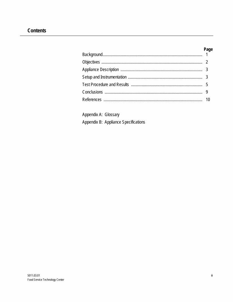
Page Background............................................................................................... 1 Objectives ................................................................................................ 2 Appliance Description .............................................................................. 3 Setup and Instrumentation ....................................................................... 3 Test Procedure and Results .................................................................... 5 Conclusions ............................................................................................. 9 References .............................................................................................. 10 Appendix A: Glossary Appendix B: Appliance Specifications
List of Figures and Tables
5011.03.01 iv Food Service Technology Center
Page 1 Adjustable refrigeration shelving system ........................................ 2 2 Beverage-Air ER48-1A2 refrigerator ............................................... 3 3 Test simulator with thermocouple configuration ............................. 4 4 Test simulator locations and configuration ...................................... 4 5 Shelf locations and test simulator configuration…........................... 5 6 24-Hour individual test simulator temperatures ............................... 6 7 24-Hour average shelf temperatures…. .......................................... 6
Page 1 Appliance Specifications ................................................................ 3 2 Energy Consumption Test Results ................................................. 7 3 24-Hour Temperature Performance ............................................... 8 4 Energy Consumption and Cost. ...................................................... 8
Figures
Tables
Beverage-Air Refrigerator Performance Report
5011.03.01 1 Food Service Technology Center
Refrigeration is an integral, and potentially expensive, part of every food service establishment. Commercial refrigeration comprises 6% of a food ser-vice operation's energy use1; in refrigeration-intensive operations, such as super markets, that percentage could be even higher. The American Society of Heating Refrigerating and Air-Conditioning Engineers (ASHRAE ) devel-oped the BSR/ASHRAE Standard 117 - 2002 Method of Testing Closed Re-frigerators, which determines the daily energy consumption of closed refrigerators. For many years the California Energy Commission (CEC) has been requiring manufacturers to provide energy performance numbers based on the ASHRAE 117 - 1992 test method (the predecessor of ASHRAE 117 - 2002) for any commercial refrigeration unit sold in the state of California for many years. The differences between 117 – 1992 and 117 – 2002 are changes in simulator mixture, placement of ambient temperature measurement device, and refrigerator loading scenario 2,3. The EPA has also established guidelines that determine performance criteria for the Energy Star label for refrigera-tors.
Dedicated to the advancement of the food service industry, the Food Service Technology Center (FSTC) has focused on the development of standard test methods for commercial food service equipment since 1987. The primary component of the FSTC is a 10,000 square-foot appliance laboratory equipped with energy monitoring and data acquisition hardware, 60 linear feet of canopy exhaust hoods integrated with utility distribution systems, ap-pliance setup and storage areas, and a state-of-the-art demonstration and training facility.
Beverage-Air’s double door reach-in refrigerator employs epoxy-coated rails for a multitude of shelf configurations, as well as a fan shut-off switch that operates when the doors open. This report presents the results of applying the ASHRAE 117 - 2002 test method to the Beverage-Air ER48-1AS double-
Background
Beverage-Air Refrigerator Performance Report
5011.03.01 2 Food Service Technology Center
door reach-in refrigerator. The glossary in Appendix A is provided so that the reader has a quick reference to the terms used in this report.
The objective of this report is to examine the operation and performance of a Beverage-Air 48-inch double-door reach-in refrigerator, under the controlled conditions of the ASHRAE's standard 117 - 2002 Method of Testing Closed Refrigerators. The scope of this testing at the FSTC is as follows:
1. Verify that the appliance is operating at the manufacturer’s rated energy input (current draw).
2. Document test simulator temperatures and appliance energy consumption during the 24-hour test.
3. Characterize the simulator temperatures and energy use during the 8-hour door openings and 16-hour idle.
4. Estimate the operating cost based on a standardized cost model.
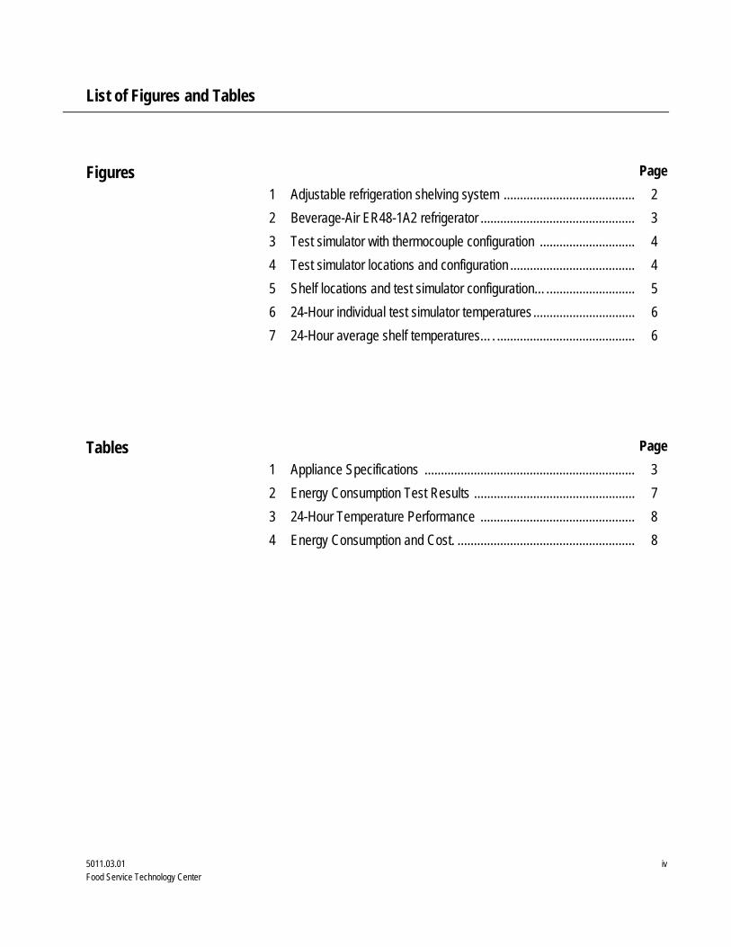
Beverage-Air’s ER48-1AS, 48-inch double-door reach-in refrigerator in-cludes epoxy coated wire rod slides (see Figure 1), which accommodates 18 x 26-inch (full size) sheet pans. The cavity is cooled by a top mounted sys-tem, which turns off when the doors are opened. The top and front are stainless steel, with aluminum comprising the case, interior and end panels (Figure 2).
Objectives
Appliance Description
Figure 1. Epoxy coated rods for adjustable shelving.
Beverage-Air Refrigerator Performance Report
5011.03.01 3 Food Service Technology Center
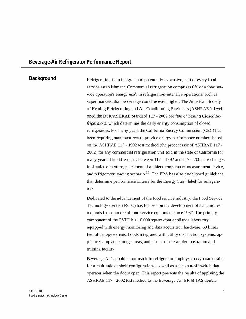
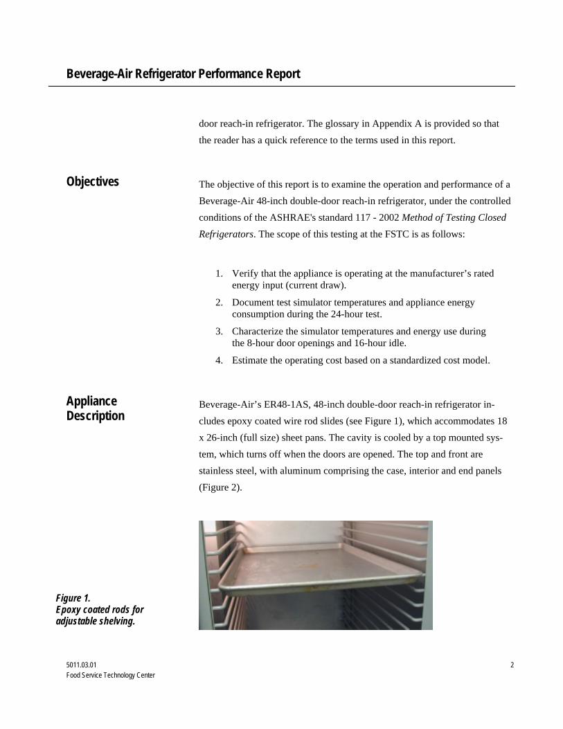
Nominal 2-inch thick R22 polyurethane insulation (foamed in place) prevents heat gain into the refrigerator cavity, while the two doors feature self-closing hinges and snap-in magnetic gaskets.
Appliance specifications are listed in Table 1, and the manufacturer’s litera-ture is in Appendix B.
Table 1. Appliance Specifications.
Manufacturer Beverage-Air
Model ER48-1AS
Generic Appliance Type Double-Door Reach-in Refrigerator
External Dimensions 52" wide x 33.5" deep x 84.5" high (including casters)
Shelf Configuration Epoxy Coated Wire Rod Slides
Current Rating 9.4 amps @ 115 volts
Refrigerant Type R134A
Refrigerant Amount 14 oz
Design Pressure 250 psig high; 250 psig low
Construction Stainless-steel doors and grill with steel gray acrylic finish for exterior sides. Exterior top bottom and back are galva-nized steel, and an anodized aluminum finish interior
Usable Volume 42.5 cubic feet
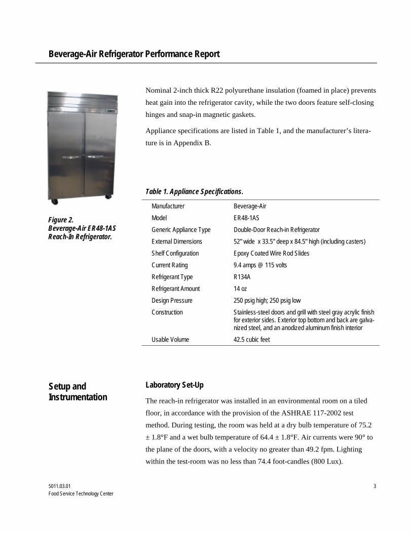
Laboratory Set-Up
The reach-in refrigerator was installed in an environmental room on a tiled floor, in accordance with the provision of the ASHRAE 117-2002 test method. During testing, the room was held at a dry bulb temperature of 75.2 ± 1.8°F and a wet bulb temperature of 64.4 ± 1.8°F. Air currents were 90° to the plane of the doors, with a velocity no greater than 49.2 fpm. Lighting within the test-room was no less than 74.4 foot-candles (800 Lux).
Figure 2. Beverage-Air ER48-1AS Reach-In Refrigerator.
Setup and Instrumentation
Beverage-Air Refrigerator Performance Report
5011.03.01 4 Food Service Technology Center
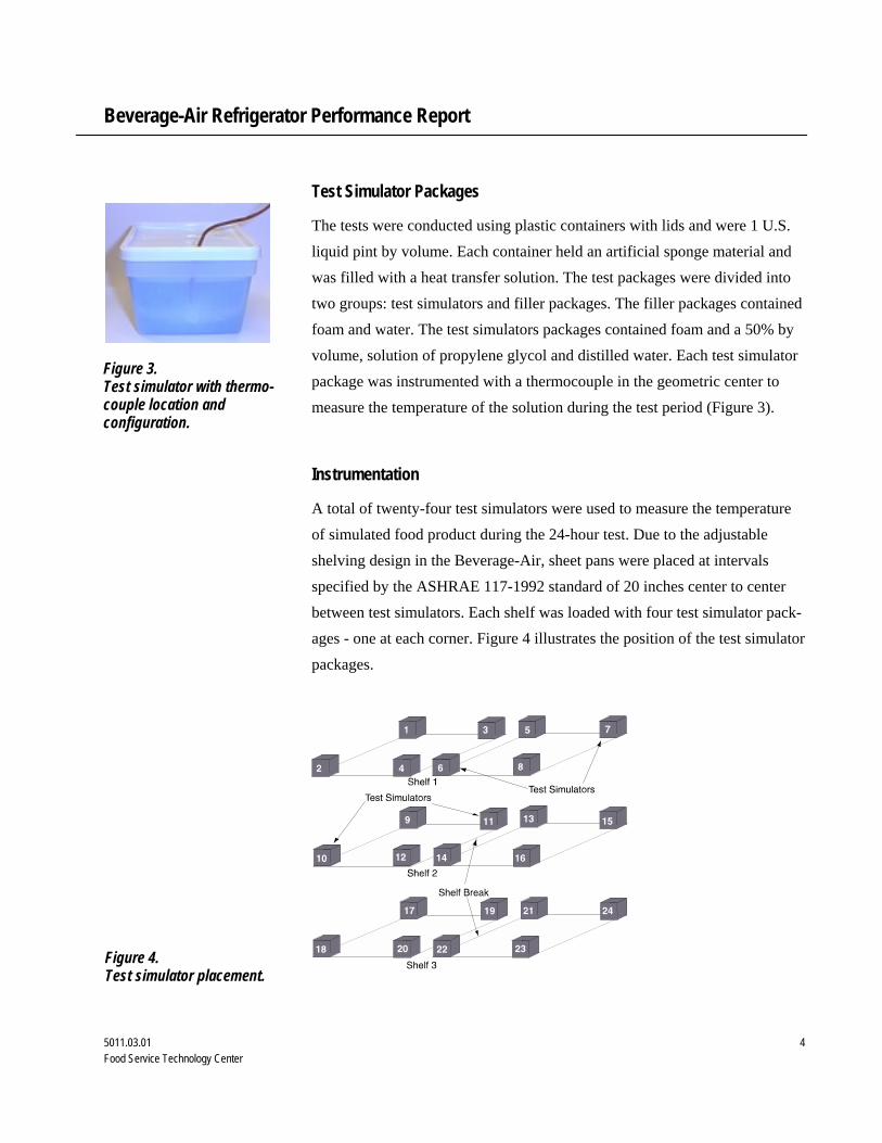
Test Simulator Packages
The tests were conducted using plastic containers with lids and were 1 U.S. liquid pint by volume. Each container held an artificial sponge material and was filled with a heat transfer solution. The test packages were divided into two groups: test simulators and filler packages. The filler packages contained foam and water. The test simulators packages contained foam and a 50% by volume, solution of propylene glycol and distilled water. Each test simulator package was instrumented with a thermocouple in the geometric center to measure the temperature of the solution during the test period (Figure 3).
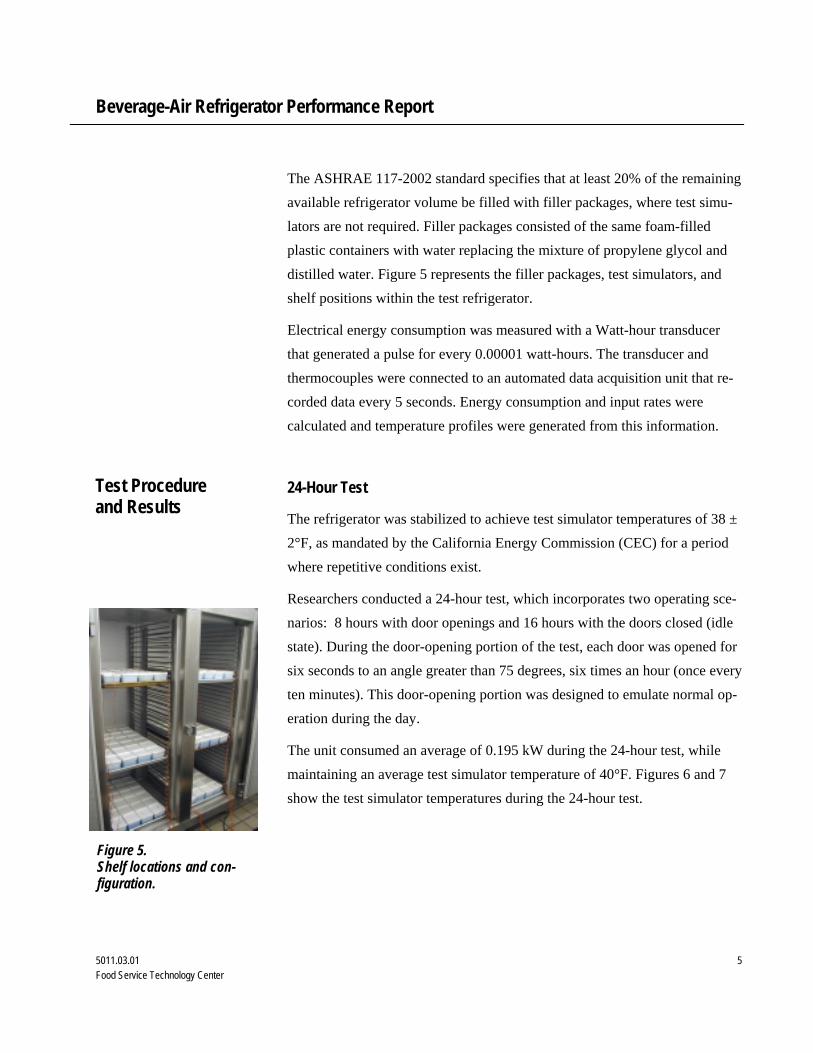
Instrumentation
A total of twenty-four test simulators were used to measure the temperature of simulated food product during the 24-hour test. Due to the adjustable shelving design in the Beverage-Air, sheet pans were placed at intervals specified by the ASHRAE 117-1992 standard of 20 inches center to center between test simulators. Each shelf was loaded with four test simulator pack-ages - one at each corner. Figure 4 illustrates the position of the test simulator packages.
Figure 3. Test simulator with thermo-couple location and configuration.
Figure 4. Test simulator placement.
Beverage-Air Refrigerator Performance Report
5011.03.01 5 Food Service Technology Center
The ASHRAE 117-2002 standard specifies that at least 20% of the remaining available refrigerator volume be filled with filler packages, where test simu-lators are not required. Filler packages consisted of the same foam-filled plastic containers with water replacing the mixture of propylene glycol and distilled water. Figure 5 represents the filler packages, test simulators, and shelf positions within the test refrigerator.
Electrical energy consumption was measured with a Watt-hour transducer that generated a pulse for every 0.00001 watt-hours. The transducer and thermocouples were connected to an automated data acquisition unit that re-corded data every 5 seconds. Energy consumption and input rates were calculated and temperature profiles were generated from this information.
24-Hour Test
The refrigerator was stabilized to achieve test simulator temperatures of 38 ± 2°F, as mandated by the California Energy Commission (CEC) for a period where repetitive conditions exist.
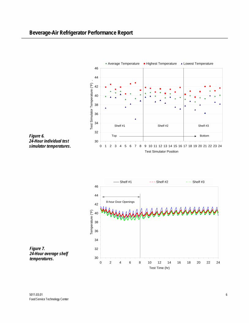
Researchers conducted a 24-hour test, which incorporates two operating sce-narios: 8 hours with door openings and 16 hours with the doors closed (idle state). During the door-opening portion of the test, each door was opened for six seconds to an angle greater than 75 degrees, six times an hour (once every ten minutes). This door-opening portion was designed to emulate normal op-eration during the day.
The unit consumed an average of 0.195 kW during the 24-hour test, while maintaining an average test simulator temperature of 40°F. Figures 6 and 7 show the test simulator temperatures during the 24-hour test.
Test Procedure and Results
Figure 5. Shelf locations and con-figuration.
Beverage-Air Refrigerator Performance Report
5011.03.01 6 Food Service Technology Center
30
32
34
36
38
40
42
44
46
0 1 2 3 4 5 6 7 8 9 10 11 12 13 14 15 16 17 18 19 20 21 22 23 24
Test Simulator Position
Test
Sim
ulat
or T
empe
ratu
re (°
F) .
Average Temperature Highest Temperature Lowest Temperature
Top Bottom
Shelf #1 Shelf #2 Shelf #3
30
32
34
36
38
40
42
44
46
0 2 4 6 8 10 12 14 16 18 20 22 24Test Time (hr)
Tem
pera
ture
(°F)
Shelf #1 Shelf #2 Shelf #3
8-hour Door Openings
Figure 6. 24-Hour individual test simulator temperatures.
Figure 7. 24-Hour average shelf temperatures.

Beverage-Air Refrigerator Performance Report
5011.03.01 7 Food Service Technology Center
Test Results
Compressor percentage run time, or duty cycle, was calculated during the 24-hour test. Duty cycle was further calculated for the 8-hour door opening por-tion and 16-hour idle portion. The compressor exhibited more frequent, short on-cycles during the 8-hour door-opening test. The average energy consump-tion rates during the 8-hour and 16-hour portions were 0.241 kW and 0.173 kW, respectively. Ambient air entering the refrigerator cavity during the door openings was the primary reason for the 28% increase in energy consumption rate. During the idle state, any loss of cavity temperature was due to heat transfer through the insulation and door seals. Table 2 summarizes the test results for the energy consumption of the refrigerator. The Beverage-Air was able to maintain an average test simulator temperature of 40°F over the 24-hour test period. Though ASHRAE 117-2002 does not currently require a specified temperature range, the CEC requires a range of 38 ± 2°F for aver-age simulator temperature. Table 3 summarizes the temperature data for the Beverage-Air refrigerator test. With an average energy consumption rate of approximately 0.195 kW during the 24-hour test, the Beverage-Air refrigera-tor used 11% less energy than a previously tested refrigerator at the Food Service Technology Center. 4
Table 2. Energy Consumption Test Results.
8-Hr Door Openings
16-Hr Idle
24-Hr Test
Compressor Duty Cycle (%) 32.2 19.5 23.8
Fan Energy Consumption (kWh) 0.580 1.160 1.740
Compressor Energy Consumption (kWh) 1.346 1.605 2.951
Total Energy Consumption (kWh) 1.926 2.765 4.691
Energy Consumption Rate (kW) 0.241 0.173 0.195

Beverage-Air Refrigerator Performance Report
5011.03.01 8 Food Service Technology Center
Table 3. 24-Hour Temperature Performance.
Ambient Dry-Bulb Temperature (°F) 74.2
Ambient Wet-Bulb Temperature (°F) 63.5
Average Temperature (AT) for All Test Simulators (°F) 40
Coldest Test Simulator Average (CTSA) Temperature (°F) 38.6
Coldest Test Simulator (CTS) Temperature (°F) 36.9
Warmest Test Simulator Average (WTSA) Temperature (°F) 41.0
Warmest Test Simulator (WTS) Temperature (°F) 42.1
Energy Model
Researchers developed an energy usage/cost model to estimate annual user costs. The model is based on operational energy use from both the door openings and closed door conditions. The door opening condition was used to estimate daily energy use of the unit, while the closed door condition was used to estimate idle state during the night. The model assumed 24 operating hours per day, 365 days per year. The energy cost was based on $0.10/kWh, a typical average energy rate for the United States. Energy consumption and operating cost are summarized in Table 4.
Table 4. Energy Consumption and Cost.
Energy Consumption (kWh/yr) Annual Operating Cost ($/yr)
Door Openings 703 70
Door Closed 1,009 101 Total 1,712 171

Beverage-Air Refrigerator Performance Report
5011.03.01 9 Food Service Technology Center
Beverage-Air's double-door reach-in refrigerator performed well during the comprehensive laboratory testing. The unit was capable of maintaining the CEC required test simulator temperatures during both door-opening and closed door portions of 38 ± 2°F. Energy consumption rate was low, at 0.195 kW for the 24-hour test relative to units previously tested at the FSTC. The reported energy consumption under 117-2002 is higher than it would be un-der 117 – 1992 due to the loading scenario that was used for this test (unit was loaded to 20% capacity instead of 100% as required for 117 - 1992). Furthermore, the Beverage-Air's low energy use qualifies it as an Energy Star refrigerator. 5
Conclusions

Beverage-Air Refrigerator Performance Report
5011.03.01 10 Food Service Technology Center
1. Claar, C.N., Mazzucchi, R.P., Heidell, J.A., 1985. The Project on Restau-rant Energy Performance (PREP) - End-Use Monitoring and Analysis. Prepared for the Office of Building Energy Research and Development, DOE, May.
2. American Society of Heating, Refrigerating and Air-Conditioning Engi-neers. ASHRAE 117 - 1992. Method of Testing Closed Refrigerators. Atlanta. American Society of Heating, Refrigerating and Air-Conditioning Engineers. Atlanta, GA.
3. American Society of Heating, Refrigerating and Air-Conditioning Engi-neers. ASHRAE 117 - 2002. Method of Testing Closed Refrigerators. Atlanta. American Society of Heating, Refrigerating and Air-Conditioning Engineers. Atlanta, GA.
4. Food Service Technology Center. 1999. Traulsen Two-Door Reach-In Refrigerator Performance Test. Report 5011.99.73 prepared for Cus-tomer Energy Management. San Francisco. Pacific Gas and Electric Company.
5. Environmental Protection Agency. 2002. Energy Star Qualified Com-mercial Solid Door Refrigerators and Freezers. http://yosemite1.epa.gov/estar/consumers.nsf/content/refrigerator.htm
References
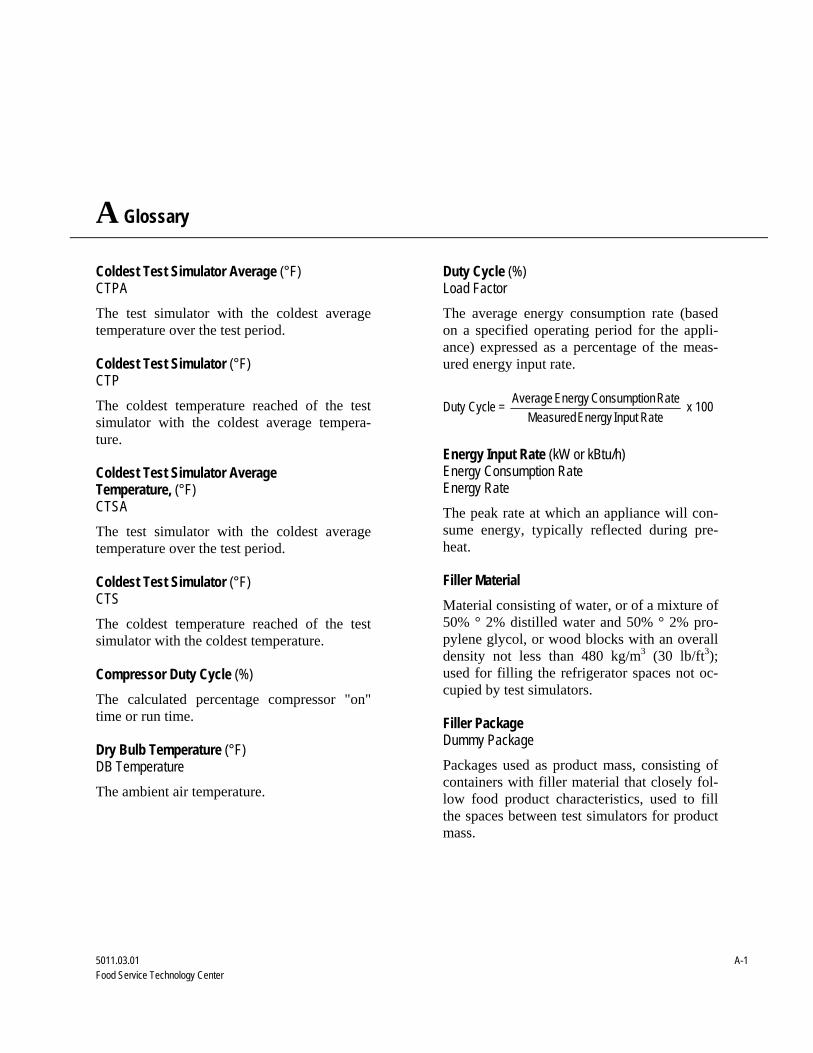
A Glossary
5011.03.01 A-1 Food Service Technology Center
Coldest Test Simulator Average (°F) CTPA The test simulator with the coldest average temperature over the test period. Coldest Test Simulator (°F) CTP The coldest temperature reached of the test simulator with the coldest average tempera-ture. Coldest Test Simulator Average Temperature, (°F) CTSA The test simulator with the coldest average temperature over the test period. Coldest Test Simulator (°F) CTS The coldest temperature reached of the test simulator with the coldest temperature. Compressor Duty Cycle (%) The calculated percentage compressor "on" time or run time. Dry Bulb Temperature (°F) DB Temperature The ambient air temperature.
Duty Cycle (%) Load Factor The average energy consumption rate (based on a specified operating period for the appli-ance) expressed as a percentage of the meas-ured energy input rate.
Duty Cycle = RateInput Energy Measured
Rate nConsumptioEnergy Average x 100
Energy Input Rate (kW or kBtu/h) Energy Consumption Rate Energy Rate The peak rate at which an appliance will con-sume energy, typically reflected during pre-heat. Filler Material Material consisting of water, or of a mixture of 50% ° 2% distilled water and 50% ° 2% pro-pylene glycol, or wood blocks with an overall density not less than 480 kg/m3 (30 lb/ft3); used for filling the refrigerator spaces not oc-cupied by test simulators. Filler Package Dummy Package Packages used as product mass, consisting of containers with filler material that closely fol-low food product characteristics, used to fill the spaces between test simulators for product mass.
Glossary
5011.03.01 A-2 Food Service Technology Center
Idle Energy Rate (kW or Btu/h) Idle Energy Input Rate Idle Rate The rate of appliance energy consumption while it is “idling” or “holding” at a stabilized operating condition or temperature. Intergrated Average Temperature, IAT (°F) Average Temperature, AT (°F) The average temperature of all of the test simulators over the test period. Measured Input Rate (kW or Btu/h) Measured Energy Input Rate Measured Peak Energy Input Rate The maximum or peak rate at which an appli-ance consumes energy, typically reflected dur-ing the initial appliance draw-down or cool-down period (i.e., the period of operation when the compressor(s) are “on”). Rated Energy Input Rate (kW, W or Btu/h, Btu/h) Input Rating (ANSI definition) Nameplate Energy Input Rate Rated Input The maximum or peak rate at which an appli-ance consumes energy as rated by the manu-facturer and specified on the nameplate. Relative Humidity (%) RH A measurement of the degree of saturation of air, with 100% indicating completely saturated air and 0% indicating completely dry air. Test Method A definitive procedure for the identification, measurement, and evaluation of one or more qualities, characteristics, or properties of a material, product, system, or service that pro-duces a test result.
Test Simulator Package Test Simulator A 1 U.S. pint (473 ml) container holding a sponge and a 50%-50% solution of water and propylene glycol with a thermocouple to measure the center temperature of the con-tainer. Warmest Test Simulator(°F) WTS The highest temperature recorded of the test simulator with the warmest average tempera-ture over the test period. Warmest Test Simulator Average(°F) WTPA The test package with the warmest average temperature over the test period. Warmest Test Simulator Average(°F) WTSA The test simulator with the warmest average temperature over the test period. Wet Bulb Temperature (°F) WB Temperature An air temperature where the temperature is a function of the saturation of the air.
B Manufacturer Specifications
5011.03.01 B-1 Food Service Technology Center
Appendix B includes the product literature for the Beverage-Air ER48-1AS refrigerator.
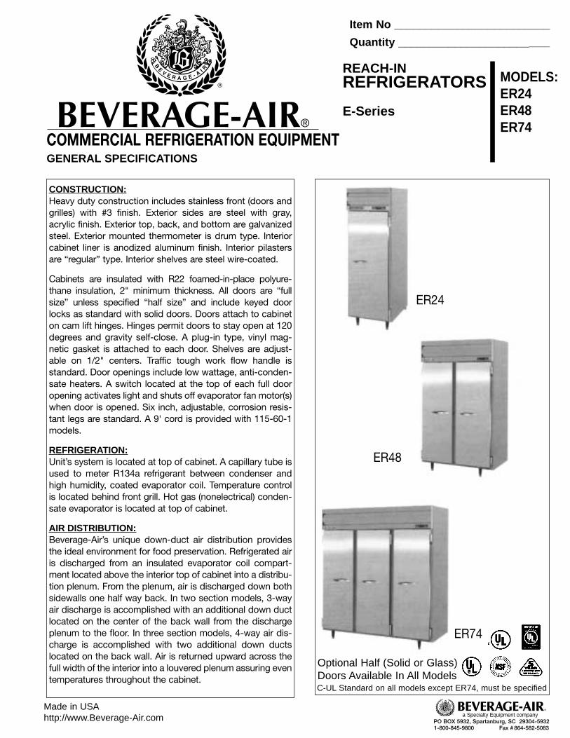
CONSTRUCTION:Heavy duty construction includes stainless front (doors andgrilles) with #3 finish. Exterior sides are steel with gray,acrylic finish. Exterior top, back, and bottom are galvanizedsteel. Exterior mounted thermometer is drum type. Interiorcabinet liner is anodized aluminum finish. Interior pilastersare “regular” type. Interior shelves are steel wire-coated.
Cabinets are insulated with R22 foamed-in-place polyure-thane insulation, 2" minimum thickness. All doors are “fullsize” unless specified “half size” and include keyed doorlocks as standard with solid doors. Doors attach to cabineton cam lift hinges. Hinges permit doors to stay open at 120degrees and gravity self-close. A plug-in type, vinyl mag-netic gasket is attached to each door. Shelves are adjust-able on 1/2" centers. Traffic tough work flow handle is standard. Door openings include low wattage, anti-conden-sate heaters. A switch located at the top of each full dooropening activates light and shuts off evaporator fan motor(s)when door is opened. Six inch, adjustable, corrosion resis-tant legs are standard. A 9' cord is provided with 115-60-1models.
REFRIGERATION:Unit’s system is located at top of cabinet. A capillary tube isused to meter R134a refrigerant between condenser andhigh humidity, coated evaporator coil. Temperature control is located behind front grill. Hot gas (nonelectrical) conden-sate evaporator is located at top of cabinet.
AIR DISTRIBUTION:Beverage-Air’s unique down-duct air distribution providesthe ideal environment for food preservation. Refrigerated airis discharged from an insulated evaporator coil compart-ment located above the interior top of cabinet into a distribu-tion plenum. From the plenum, air is discharged down bothsidewalls one half way back. In two section models, 3-wayair discharge is accomplished with an additional down ductlocated on the center of the back wall from the dischargeplenum to the floor. In three section models, 4-way air dis-charge is accomplished with two additional down ductslocated on the back wall. Air is returned upward across thefull width of the interior into a louvered plenum assuring eventemperatures throughout the cabinet.
Item No _________________________
Quantity _________________________
REACH-INREFRIGERATORS
E-Series
MODELS:ER24ER48ER74
COMMERCIAL REFRIGERATION EQUIPMENTGENERAL SPECIFICATIONS
Made in USAhttp://www.Beverage-Air.com
ER24
ER48
PO BOX 5932, Spartanburg, SC 29304-59321-800-845-9800 Fax # 864-582-5083
BEVERAGE-AIR®
a Specialty Equipment company
Optional Half (Solid or Glass)Doors Available In All Models
ER74
C-UL Standard on all models except ER74, must be specified

ER24, ER48, ER74Reach-In Refrigerators
❑ SPECIFICATIONS ER24
SOLID DOOR GLASS DOORExterior Width 26" 26"Exterior Depth, Overhandle 33 1/2" 33 1/2"Exterior Height, With Legs 84 1/2" 84 1/2"Cubic Feet 23.1 23.1Cabinet Voltage (50 Cycle Available) 115 115Horsepower 1/4 1/4Amps 5.7 5.7Recommended BTU/HR* 1900 1900Crated Weight 351 360Shelves 3 3Shelf Dimension 20 3/4" x 26" 20 3/4" x 26"
❑ SPECIFICATIONS ER48
SOLID DOOR GLASS DOORExterior Width 52" 52"Exterior Depth, Overhandle 33 1/2" 33 1/2"Exterior Height, With Legs 84 1/2" 84 1/2"Cubic Feet 46.6 46.6Cabinet Voltage (50 Cycle Available) 115 115Horsepower 1/3 1/3Amps 9.4 9.4Recommended BTU/HR* 2500 2500Crated Weight 562 580Shelves 6 6Shelf Dimension 20 3/4" x 26" 20 3/4" x 26"
❑ SPECIFICATIONS ER74
SOLID DOOR GLASS DOORExterior Width 78" 78"Exterior Depth, Overhandle 33 1/2" 33 1/2"Exterior Height, With Legs 84 1/2" 84 1/2"Cubic Feet 74 74Cabinet Voltage (50 Cycle Available) 115 115Horsepower 1/2 3/4Amps 10.5 12.0Recommended BTU/HR* 4550 6000Crated Weight 791 818Shelves 9 9Shelf Dimension 20 3/4" x 26" 20 3/4" x 26"NOTES:*Net refrigeration capacity of cabinet at 20˚ F evaporator temperature & 120˚ F condenser temperature. Heat load generated by cabinet is 2565 BTU/HR for ER24, 3375 for ER48, and 6143 for ER74.ER-244874-BW
PAN AND TRAY SLIDE COMBINATIONSNO. 1 STAINLESS STEEL ANGLE SLIDE❑ ■ Part No. 61C08-007A
■ Each pair rim supports 2 ea. 12"x20" hotel pans - 3" minimum spacing
■ Requires use of heavy duty pilasterkit No. 61C08-010A(2 required per section)
Max. Cap. 16Pr/Sec
NO. 2 STAINLESS STEEL ANGLE SLIDE❑ ■ Part No. 61C08-008A
■ Each pair rim supports 1 ea.18" x 26" bun pan or 2 ea. 14"x18" bun pans - 2" minimum spacing
■ Requires use of wide pilaster, kitNo. 61C08-011A (2 required persection)
Max. Cap. 26Pr/Sec
OPTIONAL EQUIPMENT❑ Stainless Steel Breakers ❑ Rehinging of Doors❑ Prison Package ❑ Stainless Steel Shelves❑ Casters ❑ Half Solid Doors❑ Remote Hook-Up ❑ Half Glass Doors❑ Digital Thermometer ❑ Full Glass Doors❑ Gastronorm Pan Slides ❑ Locks - Glass Door
(Check factory)
PO BOX 5932, Spartanburg, SC 29304-59321-800-845-9800 Fax # 864-582-5083
a Specialty Equipment company
NO. 3 STAINLESS STEEL ANGLE SLIDE❑ ■ Part No. 61C08-009A
■ Each pair bottom supports 2 ea.12" x 20" hotel pans or 1 ea. 18" x26" bun pan or 2 ea. 14" x 18" bun pans
■ Requires use of heavy duty pilaster, kitNo. 61C08-010A (2 required per section)
Max. Cap. 16Pr/Sec
NO. 4 EPOXY COATED WIRE ROD SLIDE❑ ■ Part No. 61C31-053A
■ Rim supports a maximum of 19 ea. 18" x 26" bun pans per half section with 1 1/2" fixed spacing
■ Pilasters not required - Adjustableto pan width
Max. Cap. 38Pr/Sec
File # ____________________________
Spec. __________________________