Embed Size (px)
Citation preview
1Laurent S. Nadolski Beam diagnostics CAS, 2008, Dourdan
Version 2.0
Between Model and Reality IIor why diagnostics are so crucial for
running an accelerator facility?
Laurent S. Nadolski
Accelerator Physics Group
Synchrotron SOLEIL

2Laurent S. Nadolski Beam diagnostics CAS, 2008, Dourdan
Version 2.0
Layout
• Introduction – Main focus on circular synchrotron light sources– Beam line stability � See S. Hustache’s talk on June 5th
• Example of a 3GLS needs for commissioning (SOLEIL)• Stability requirements for accelerators
– Noise sources and solutions– Closed orbit stability– Tune, chromaticity, coupling stability
• Collective effects• Other needs for operation• Conclusion
Note: General overview w/o going into details� See detailed talks during this diagnostics CAS
3Laurent S. Nadolski Beam diagnostics CAS, 2008, Dourdan
Version 2.0
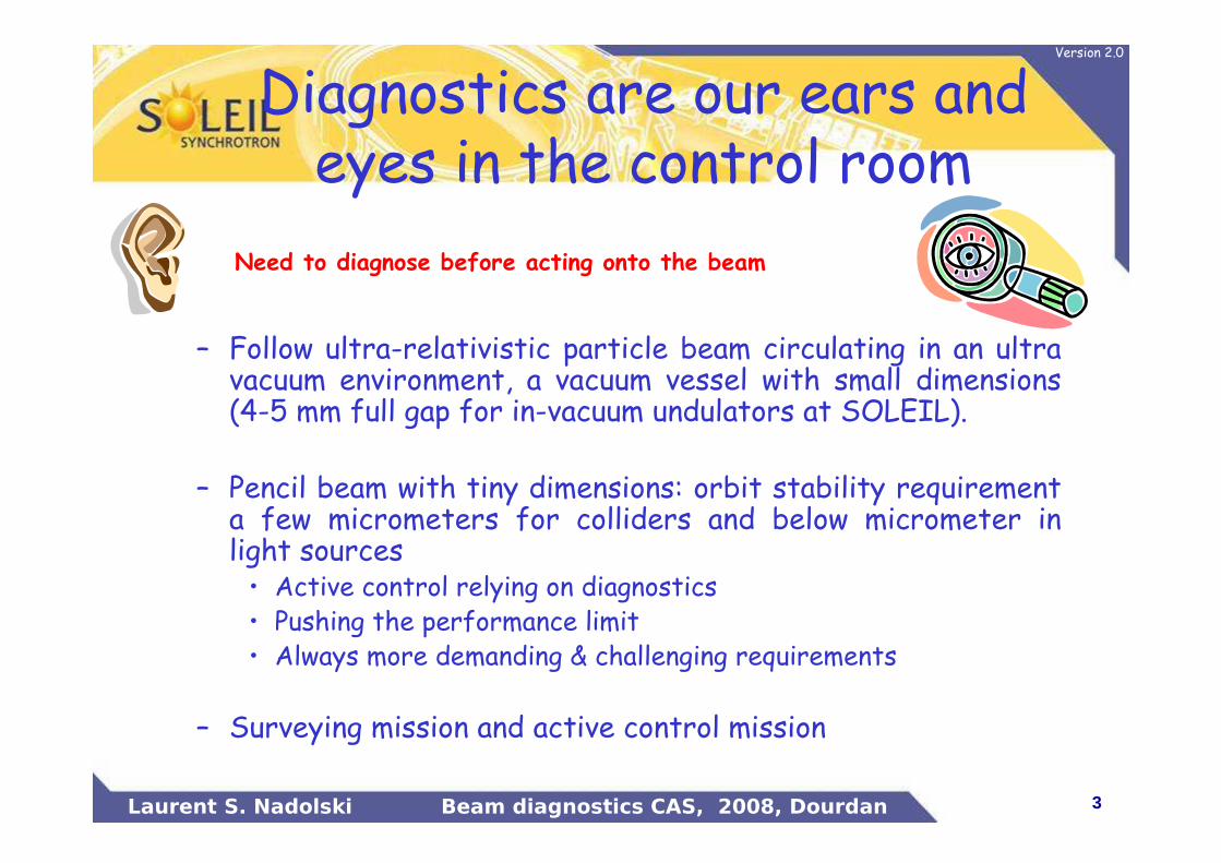
Diagnostics are our ears and eyes in the control room
– Follow ultra-relativistic particle beam circulating in an ultra vacuum environment, a vacuum vessel with small dimensions (4-5 mm full gap for in-vacuum undulators at SOLEIL).
– Pencil beam with tiny dimensions: orbit stability requirement a few micrometers for colliders and below micrometer in light sources• Active control relying on diagnostics• Pushing the performance limit• Always more demanding & challenging requirements
– Surveying mission and active control mission
Need to diagnose before acting onto the beam
4Laurent S. Nadolski Beam diagnostics CAS, 2008, Dourdan
Version 2.0
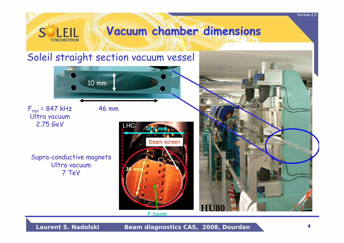
Vacuum chamber dimensionsVacuum chamber dimensions
HU80
46 mm
10 mm
Soleil straight section vacuum vessel
Supra-conductive magnetsUltra vacuum
7 TeV
Frev = 847 kHzUltra vacuum2.75 GeV
P-beam
5Laurent S. Nadolski Beam diagnostics CAS, 2008, Dourdan
Version 2.0
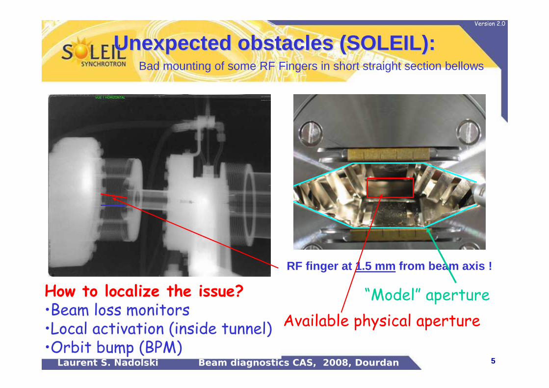
Bad mounting of some RF Fingers in short straight section bellows
RF finger at 1.5 mm from beam axis !
Available physical aperture
How to localize the issue?•Beam loss monitors•Local activation (inside tunnel) •Orbit bump (BPM)
Unexpected obstacles (SOLEIL):Unexpected obstacles (SOLEIL):
“Model” aperture
6Laurent S. Nadolski Beam diagnostics CAS, 2008, Dourdan
Version 2.0
Reality differs all the time from Models
No large accelerator run the first day with nominal performance just by pushing a simple “button”.
There are expected and unexpected sources of (static and time variable) perturbations
7Laurent S. Nadolski Beam diagnostics CAS, 2008, Dourdan
Version 2.0
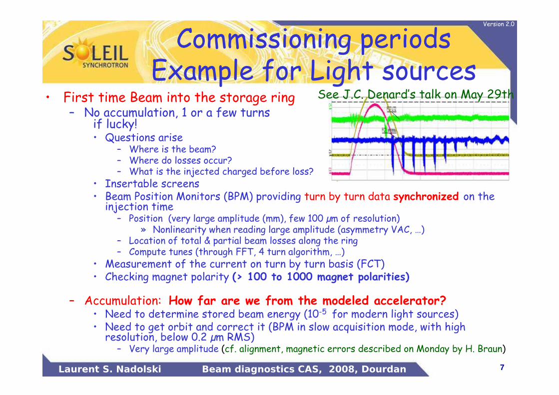
Commissioning periodsExample for Light sources
• First time Beam into the storage ring– No accumulation, 1 or a few turns
if lucky!• Questions arise
– Where is the beam?– Where do losses occur?– What is the injected charged before loss?
• Insertable screens• Beam Position Monitors (BPM) providing turn by turn data synchronized on the injection time
– Position (very large amplitude (mm), few 100 µm of resolution)» Nonlinearity when reading large amplitude (asymmetry VAC, …)
– Location of total & partial beam losses along the ring – Compute tunes (through FFT, 4 turn algorithm, …)
• Measurement of the current on turn by turn basis (FCT)• Checking magnet polarity (> 100 to 1000 magnet polarities)
– Accumulation: How far are we from the modeled accelerator?• Need to determine stored beam energy (10-5 for modern light sources) • Need to get orbit and correct it (BPM in slow acquisition mode, with high resolution, below 0.2 µm RMS)
– Very large amplitude (cf. alignment, magnetic errors described on Monday by H. Braun)
See J.C. Denard’s talk on May 29th
8Laurent S. Nadolski Beam diagnostics CAS, 2008, Dourdan
Version 2.0
Stacking the beam con’t• Need to correct the betatron tunes
– In general tunes are off by 0.5 to a few units ! (cf. Monday H. Braun’s talk)
– Wrong tunes can prevent good injection efficiency, give large orbit distortion, jeopardize any orbit correction, .... » Measured by excitation of the transverse motion (kicker, shaker, stripline, …)
» Analysis of turn by turn data (BPM electronics, FFT)
• Current, lifetime measurement (DCCT, …)• Need to insure the beam is going through the center of the quadrupole and sextupole magnets– Correct for magnetic center determination errors, alignment errors of both magnets and BPM blocks into the tunnel)
– Standard technique is known as Beam Based Alignment» Use of the BPM to measure the closed orbit for various steerer settings
» Low noise BPM electronics to reach center values below micrometer level
For Lattice measurement, see J. Wenninger’s talk on May 31st
9Laurent S. Nadolski Beam diagnostics CAS, 2008, Dourdan
Version 2.0
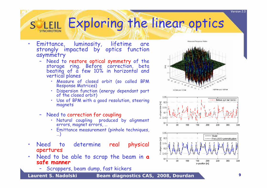
Exploring the linear optics
• Emittance, luminosity, lifetime are strongly impacted by optics function asymmetry– Need to restore optical symmetry of the
storage ring. Before correction, beta beating of a few 10% in horizontal and vertical planes• Measure of closed orbit (so called BPM
Response Matrices)• Dispersion function (energy dependant part
of the closed orbit)• Use of BPM with a good resolution, steering
magnets
– Need to correction for coupling• Natural coupling produced by alignment
errors, magnet errors, …• Emittance measurement (pinhole techniques,
…)
• Need to determine real physical apertures
• Need to be able to scrap the beam in a safe manner– Scrappers, beam dump, fast kickers
10Laurent S. Nadolski Beam diagnostics CAS, 2008, Dourdan
Version 2.0
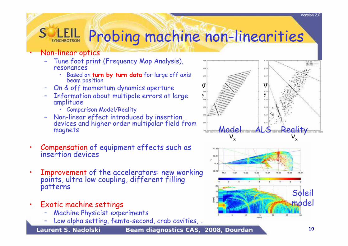
Probing machine non-linearities• Non-linear optics
– Tune foot print (Frequency Map Analysis), resonances• Based on turn by turn data for large off axis
beam position– On & off momentum dynamics aperture– Information about multipole errors at large
amplitude• Comparison Model/Reality
– Non-linear effect introduced by insertion devices and higher order multipolar field from magnets
• Compensation of equipment effects such as insertion devices
• Improvement of the accelerators: new working points, ultra low coupling, different filling patterns
• Exotic machine settings– Machine Physicist experiments– Low alpha setting, femto-second, crab cavities, ..
νxνx
νy
νy
Soleilmodel
ALSModel Reality
11Laurent S. Nadolski Beam diagnostics CAS, 2008, Dourdan
Version 2.0
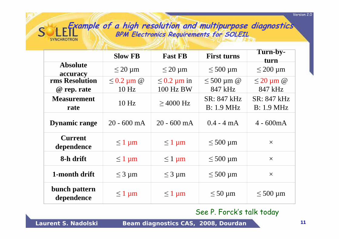
Example of a high resolution and multipurpose diagnostics BPM Electronics Requirements for SOLEIL
See P. Forck’s talk today
Slow FB Fast FB First turnsTurn-by-
turnAbsolute accuracy
≤ 20 µm ≤ 20 µm ≤ 500 µm ≤ 200 µm
rms Resolution @ rep. rate
≤ 0.2 µm@ 10 Hz
≤ 0.2 µmin 100 Hz BW
≤ 500 µm @ 847 kHz
≤ 20 µm@ 847 kHz
Measurement rate
10 Hz ≥ 4000 HzSR: 847 kHzB: 1.9 MHz
SR: 847 kHzB: 1.9 MHz
Dynamic range 20 - 600 mA 20 - 600 mA 0.4 - 4 mA 4 - 600mA
Current dependence
≤ 1 µm ≤ 1 µm ≤ 500 µm ×
8-h drift ≤ 1 µm ≤ 1 µm ≤ 500 µm ×
1-month drift ≤ 3 µm ≤ 3 µm ≤ 500 µm ×
bunch pattern dependence
≤ 1 µm ≤ 1 µm ≤ 50 µm ≤ 500 µm

12Laurent S. Nadolski Beam diagnostics CAS, 2008, Dourdan
Version 2.0
Stability criteria for different facilities
What are the machine and user requirements?
How to maintain performance for user operation?
How to reach a beam availability larger than 96%?
How to operate without damaging the accelerator facility?
13Laurent S. Nadolski Beam diagnostics CAS, 2008, Dourdan
Version 2.0
Requirements for colliders
• Lepton accelerators (LEP, PEPII, KEK-B,…)– Collider luminosity and collision stability– Effective Emittance preservation– Minimization of coupling (orbit in sextupoles)– Minimization of spurious dispersion (orbit in quadrupoles)– Tune and orbit feedbacks mostly during energy ramping
• Hadron colliders (HERA, LHC, RHIC, Tevatron, …)– Keep the beam into the pipe
• Significant amount of energy stored into the beam– Quench superconducting magnets– Drill holes into the vacuum vessel and/ or serious damage
– Capacity to control particle losses in the machine– Orbit stability driven by luminosity inside the experimental insertions: 25 µm
constraint at collimators for LHC– Energy preservation below 10-4 at LHC– Ramping the beams from injection energy (450 GeV) to collision energy (7
TeV)• Synchronization of the magnets• Different working point in tune diagram• Avoid crossing resonances in tune diagram• LHC: ∆ν < 10-3, ∆ξ = 2±1 (ξ changed by >100 units during ramping)• � orbit, tune, chromaticity and coupling feedforward/feedbacks
14Laurent S. Nadolski Beam diagnostics CAS, 2008, Dourdan
Version 2.0
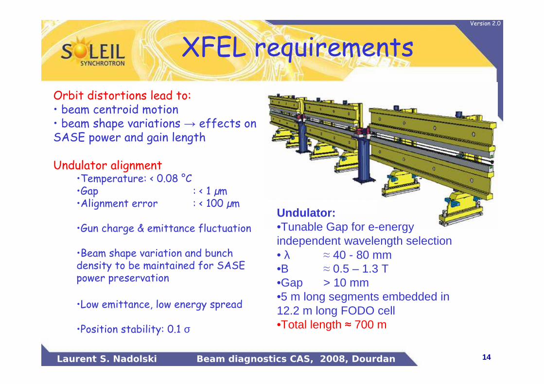
Orbit distortions lead to:• beam centroid motion• beam shape variations → effects on SASE power and gain length
Undulator alignment•Temperature: < 0.08 °C•Gap : < 1 µm•Alignment error : < 100 µm
•Gun charge & emittance fluctuation
•Beam shape variation and bunch density to be maintained for SASE power preservation
•Low emittance, low energy spread
•Position stability: 0.1 σ
XFEL requirements
Undulator:•Tunable Gap for e-energy independent wavelength selection• λ ≈ 40 - 80 mm•B ≈ 0.5 – 1.3 T•Gap > 10 mm•5 m long segments embedded in 12.2 m long FODO cell•Total length ≈ 700 m
15Laurent S. Nadolski Beam diagnostics CAS, 2008, Dourdan
Version 2.0
Third generation Synchrotron Light Sources
• Brilliance preservation• (Ultra) low emittance• Constant (large) lifetime• Sub micron orbit stability (< 0.1 σ)• Energy stability (< 10-4 to 10-5) for spectral resolution
• User freely controlled insertion devices – Has to be transparent for all the users
• Tune variations (10-3), low coupling (1-0.1%) and sometime chromaticity preservation
BI I
x z x x z z
∝ ≡ε ε σ σ σ σ' '
See AS. Mueller’s talk on June 3nd
16Laurent S. Nadolski Beam diagnostics CAS, 2008, Dourdan
Version 2.0
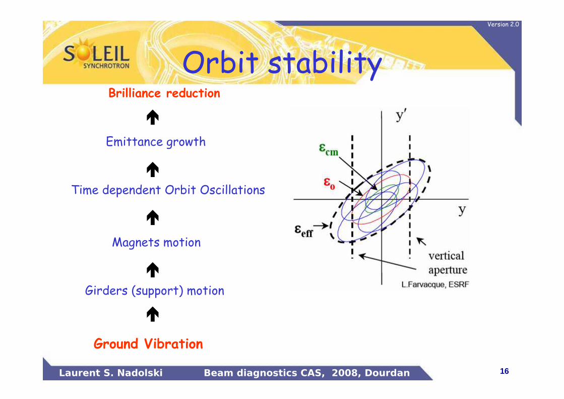
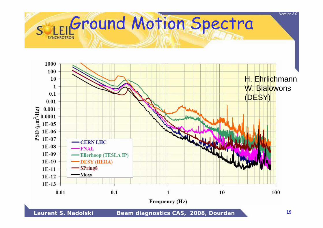
Ground Vibration
�
Girders (support) motion
�
Magnets motion
�
Time dependent Orbit Oscillations
Emittance growth
Brilliance reduction
�
�
Orbit stability
17Laurent S. Nadolski Beam diagnostics CAS, 2008, Dourdan
Version 2.0
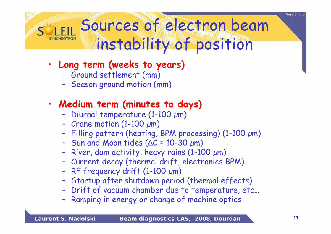
Sources of electron beam instability of position
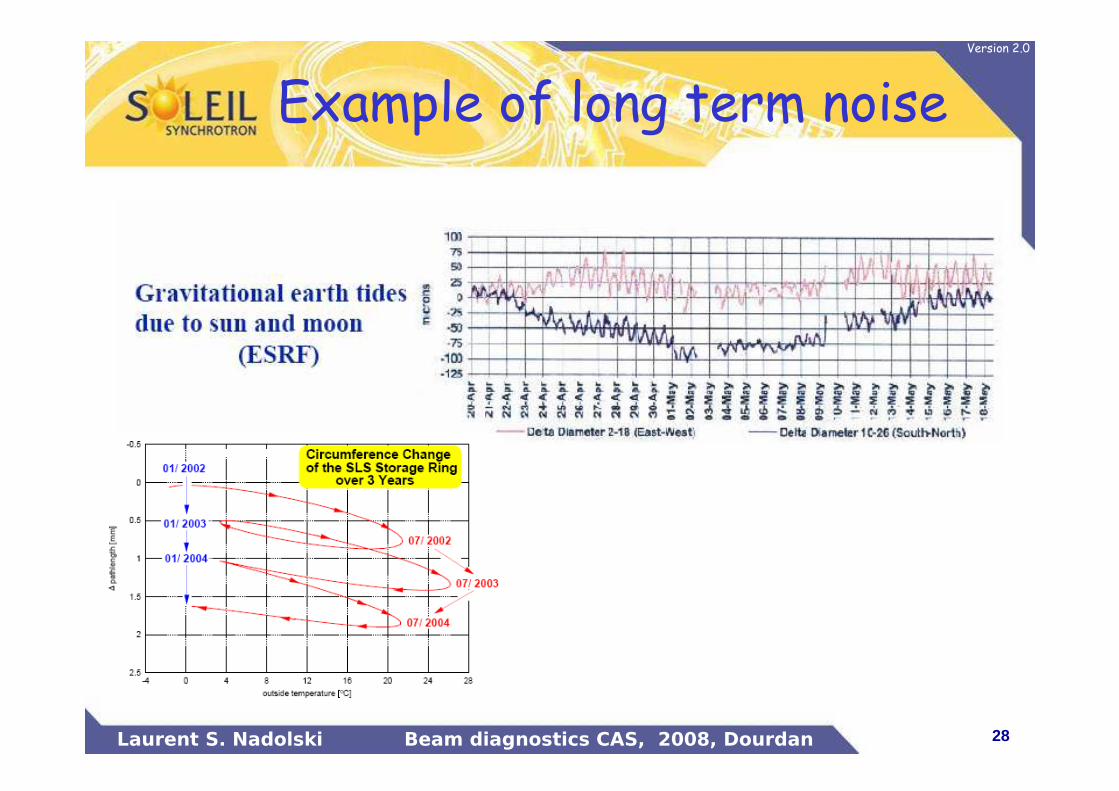
• Long term (weeks to years)– Ground settlement (mm)– Season ground motion (mm)
• Medium term (minutes to days)– Diurnal temperature (1-100 µm)– Crane motion (1-100 µm)– Filling pattern (heating, BPM processing) (1-100 µm)– Sun and Moon tides (∆C = 10-30 µm)– River, dam activity, heavy rains (1-100 µm)– Current decay (thermal drift, electronics BPM)– RF frequency drift (1-100 µm)– Startup after shutdown period (thermal effects)– Drift of vacuum chamber due to temperature, etc…– Ramping in energy or change of machine optics
18Laurent S. Nadolski Beam diagnostics CAS, 2008, Dourdan
Version 2.0
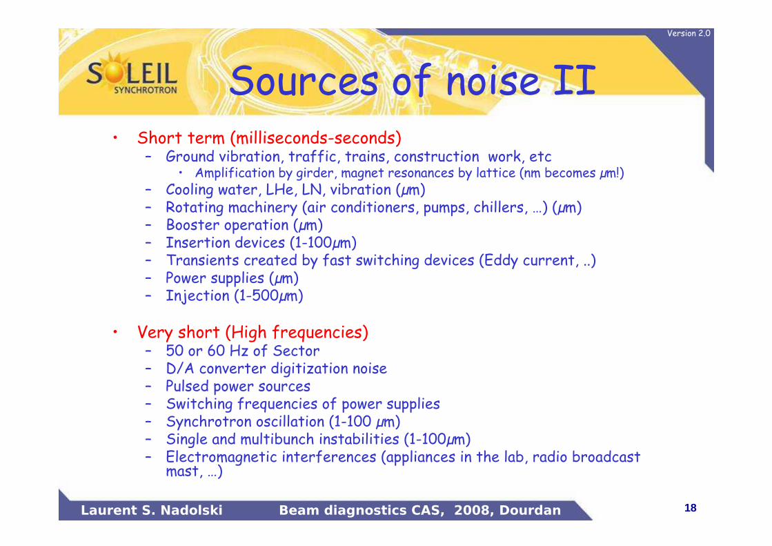
Sources of noise II• Short term (milliseconds-seconds)
– Ground vibration, traffic, trains, construction work, etc• Amplification by girder, magnet resonances by lattice (nm becomes µm!)
– Cooling water, LHe, LN, vibration (µm)– Rotating machinery (air conditioners, pumps, chillers, …) (µm)– Booster operation (µm)– Insertion devices (1-100µm) – Transients created by fast switching devices (Eddy current, ..)– Power supplies (µm)– Injection (1-500µm)
• Very short (High frequencies)– 50 or 60 Hz of Sector– D/A converter digitization noise– Pulsed power sources– Switching frequencies of power supplies– Synchrotron oscillation (1-100 µm)– Single and multibunch instabilities (1-100µm)– Electromagnetic interferences (appliances in the lab, radio broadcast
mast, …)
19Laurent S. Nadolski Beam diagnostics CAS, 2008, Dourdan
Version 2.0
Ground Motion Spectra
H. EhrlichmannW. Bialowons(DESY)
20Laurent S. Nadolski Beam diagnostics CAS, 2008, Dourdan
Version 2.0
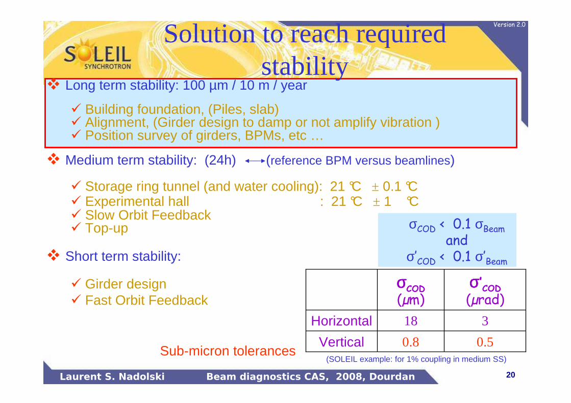
� Long term stability: 100 µm / 10 m / year
� Building foundation, (Piles, slab)� Alignment, (Girder design to damp or not amplify vibration )� Position survey of girders, BPMs, etc …
� Medium term stability: (24h) (reference BPM versus beamlines)
� Storage ring tunnel (and water cooling): 21 °C ± 0.1 °C� Experimental hall : 21 °C ± 1 °C� Slow Orbit Feedback� Top-up
� Short term stability:
� Girder design� Fast Orbit Feedback
0.50.8Vertical
318Horizontal
σσσσ’COD
(µrad)σσσσCOD
(µm)
(SOLEIL example: for 1% coupling in medium SS)Sub-micron tolerances
Solution to reach required stability
σCOD < 0.1 σBeam
and σ’COD < 0.1 σ’Beam

21Laurent S. Nadolski Beam diagnostics CAS, 2008, Dourdan
Version 2.0
Heavy concrete
Overhead crane 7 t
Exp. Hall slabthickness 0.75 mSR tunnel slab
thickness 0.95 m
Offices
Prep Lab.
140 Piles Φ 80 416 Piles Φ 60
Slab settlement < 50 µm /yearVibrations amplitude < ± 0.5 µm
95 cm thick slabs laying on piles for Storage Ring and Exp. HallBuilding design: SOLEIL exampleBuilding design: SOLEIL example
22Laurent S. Nadolski Beam diagnostics CAS, 2008, Dourdan
Version 2.0
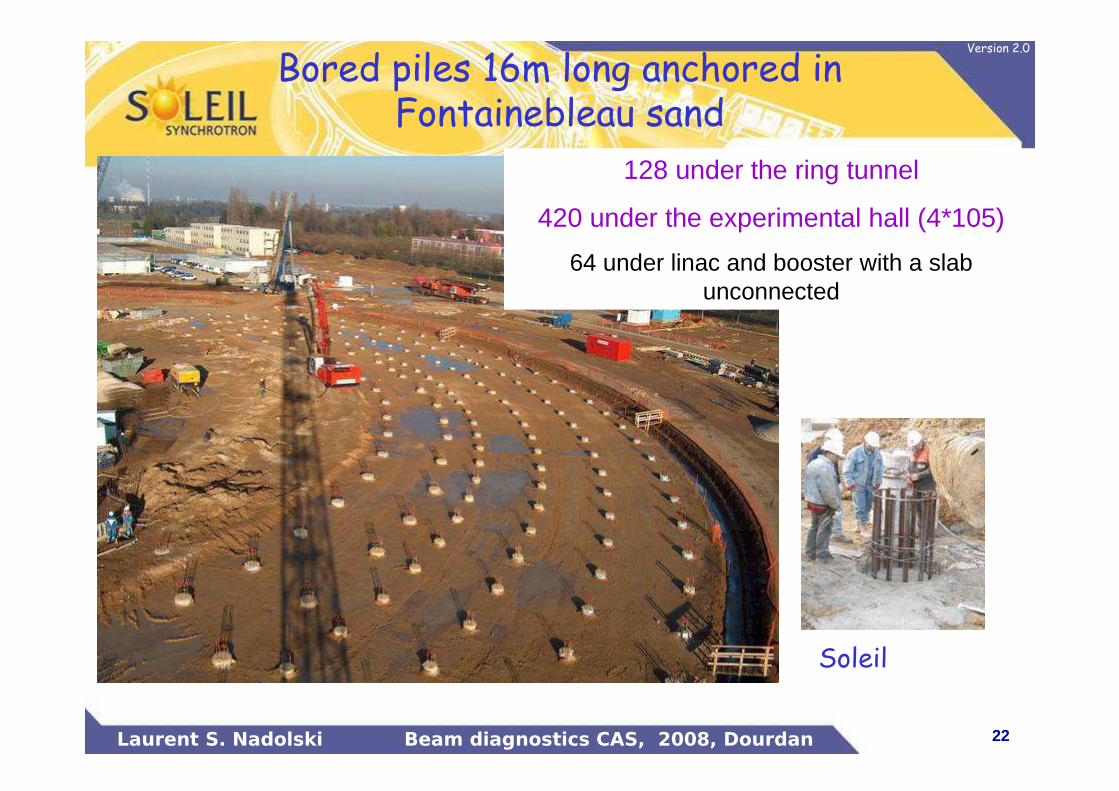
128 under the ring tunnel
420 under the experimental hall (4*105)
64 under linac and booster with a slab unconnected
Soleil
Bored piles 16m long anchored in Fontainebleau sand
23Laurent S. Nadolski Beam diagnostics CAS, 2008, Dourdan
Version 2.0
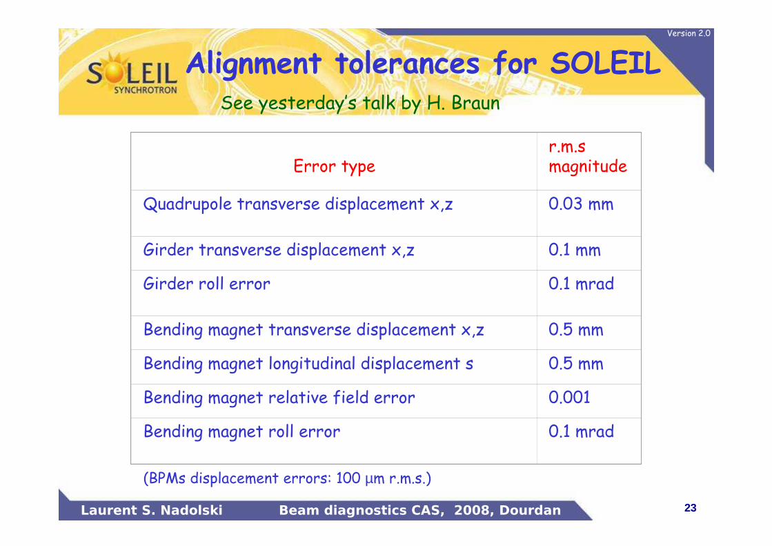
Error typer.m.smagnitude
Quadrupole transverse displacement x,z 0.03 mm
Girder transverse displacement x,z 0.1 mm
Girder roll error 0.1 mrad
Bending magnet transverse displacement x,z 0.5 mm
Bending magnet longitudinal displacement s 0.5 mm
Bending magnet relative field error 0.001
Bending magnet roll error 0.1 mrad
(BPMs displacement errors: 100 µm r.m.s.)
See yesterday’s talk by H. Braun
Alignment tolerances for SOLEIL
24Laurent S. Nadolski Beam diagnostics CAS, 2008, Dourdan
Version 2.0
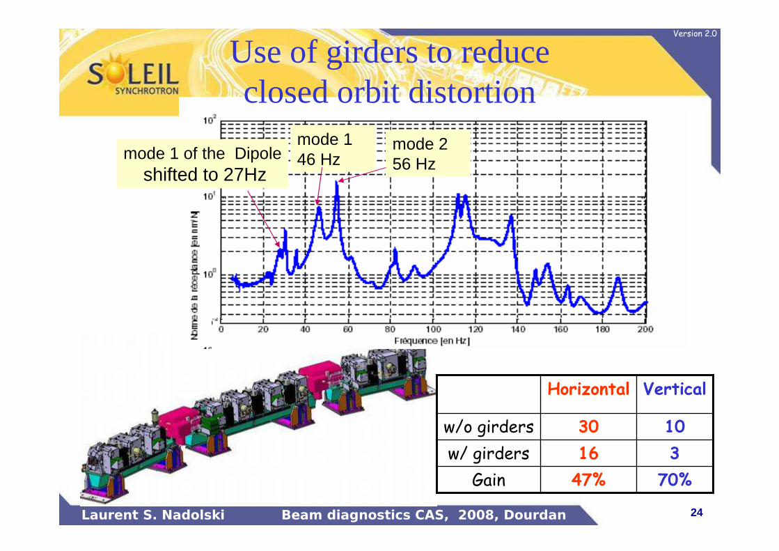
mode 1 46 Hzmode 1 of the Dipole
shifted to 27Hz
mode 2 56 Hz
70%47%Gain
316w/ girders
1030w/o girders
VerticalHorizontal
Use of girders to reduce closed orbit distortion
25Laurent S. Nadolski Beam diagnostics CAS, 2008, Dourdan
Version 2.0
507
5085098
1
18
524523522521520
519518
517
51615
514513
512511
510
506505
504503
502501
123121
109
101
309
409410
310 311
411412
413414
314313
312
415
416
316315
215216
209210 211
212213
214
209210 211
214213
212
301
401402
302
303
403404
405406
306305
304
206205
204203
202201
4061407
319
419420
320321
421 422 423 424
324323322
224223222221220219
418
208
308
408
307207
218
318
417
317
217
507508
5098
1
18
524523522521520519
518
51751615514513512
511510
506505
504503
502501
123121
117115
109
101
309
409
410
310311
411 412413
414
314313312
415 416
316315
215 216
209
210211
212 213 214
209
210211
214213212
301
401402
302303
403404
405406
306305304
206205
204203
202201
4061407
319
419 420
320 321
421 422 423 424
324323322
224223222221220219
418
208
308
408
307
207
218
318
417
317
217
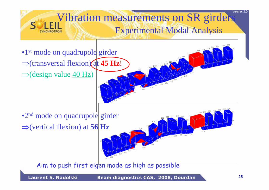
Vibration measurements on SR girdersExperimental Modal Analysis
•1st mode on quadrupole girder
⇒(transversal flexion) at45 Hz!⇒(design value 40 Hz)
•2nd mode on quadrupole girder
⇒⇒⇒⇒(vertical flexion) at56 Hz
Aim to push first eigen mode as high as possible
26Laurent S. Nadolski Beam diagnostics CAS, 2008, Dourdan
Version 2.0
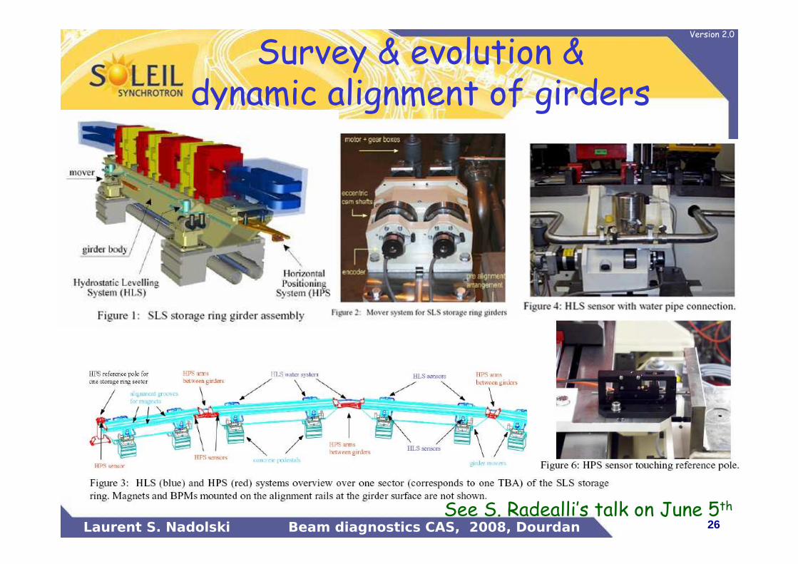
Survey & evolution & dynamic alignment of girders
See S. Radealli’s talk on June 5th
27Laurent S. Nadolski Beam diagnostics CAS, 2008, Dourdan
Version 2.0
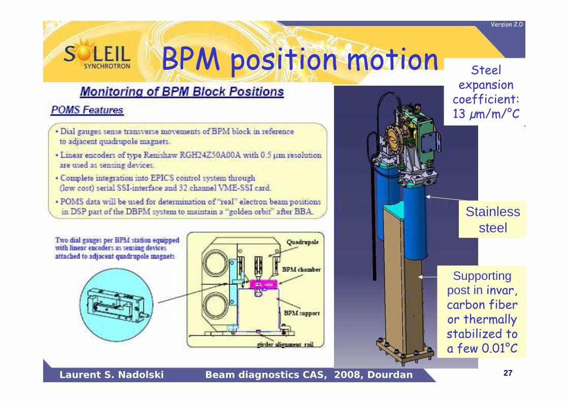
BPM position motion
Supporting post in invar, carbon fiber or thermally stabilized to a few 0.01°C
Stainless steel
Steel expansion coefficient: 13 µm/m/°C
28Laurent S. Nadolski Beam diagnostics CAS, 2008, Dourdan
Version 2.0
Example of long term noise
29Laurent S. Nadolski Beam diagnostics CAS, 2008, Dourdan
Version 2.0
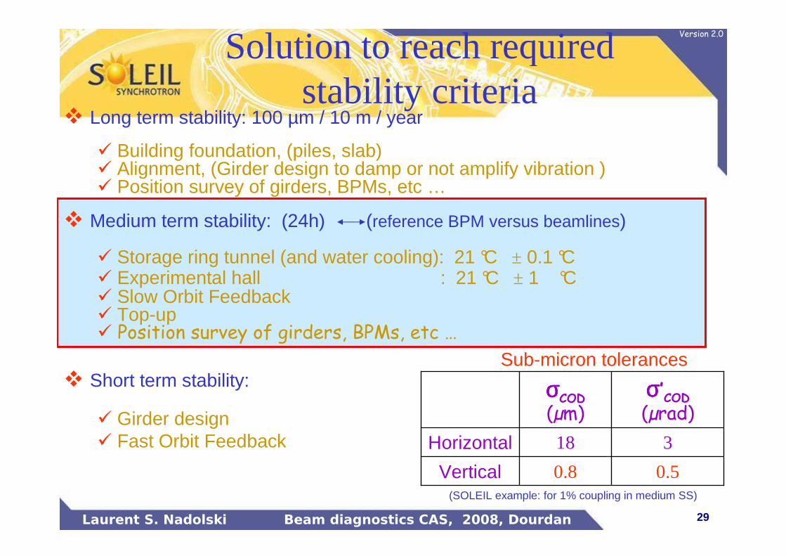
� Long term stability: 100 µm / 10 m / year
� Building foundation, (piles, slab)� Alignment, (Girder design to damp or not amplify vibration )� Position survey of girders, BPMs, etc …
� Medium term stability: (24h) (reference BPM versus beamlines)
� Storage ring tunnel (and water cooling): 21 °C ± 0.1 °C� Experimental hall : 21 °C ± 1 °C� Slow Orbit Feedback� Top-up� Position survey of girders, BPMs, etc …
� Short term stability:
� Girder design� Fast Orbit Feedback
0.50.8Vertical
318Horizontal
σσσσ’COD
(µrad)σσσσCOD
(µm)
(SOLEIL example: for 1% coupling in medium SS)
Sub-micron tolerances
Solution to reach required stability criteria

30Laurent S. Nadolski Beam diagnostics CAS, 2008, Dourdan
Version 2.0
Natural drift of orbit w/o FB
Current
X BPM1
X BPM2
Z BPM1
Z BPM2
A
50 µm
1 h
31Laurent S. Nadolski Beam diagnostics CAS, 2008, Dourdan
Version 2.0
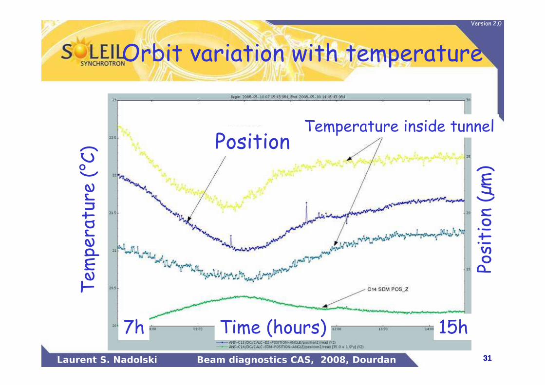
Orbit variation with temperature
Tem
perature (°C)
Position (µm
)
PositionTemperature inside tunnel
Time (hours)7h 15h

32Laurent S. Nadolski Beam diagnostics CAS, 2008, Dourdan
Version 2.0
1 m
Jets froids
1,48 m (UTA axis)1.20 m (Beam axis)
� The achieved static (average) air temperature in the area of the girders is of 19.5 ± 0.3 °C in the longitudinal direction. UTA regulation should insure the temporal stability within ± 0.1 °C.
(altimetry)
Tunnel temperature regulation

33Laurent S. Nadolski Beam diagnostics CAS, 2008, Dourdan
Version 2.0
Top-up injection and light sources
• Constant thermal load on beam-line optics (mirror alignment, thermal optical bumps, …)
• Constant thermal load on accelerator equipments. Reduction of thermal drift on BPM electronics.
• Only way to reach sub micron stability level• Not suitable for all user needs (long integration
time, image scanning, …)
34Laurent S. Nadolski Beam diagnostics CAS, 2008, Dourdan
Version 2.0
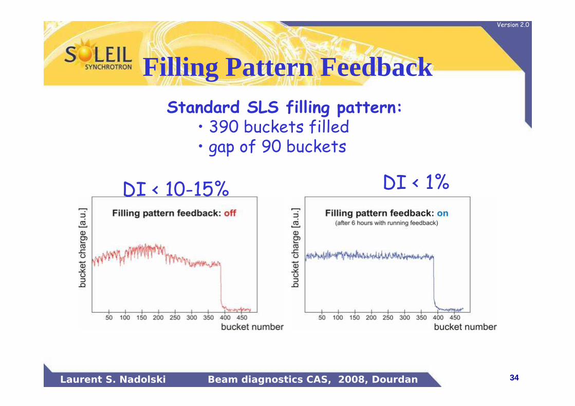
Standard SLS filling pattern:• 390 buckets filled• gap of 90 buckets
Filling Pattern Feedback
DI < 1%DI < 10-15%

35Laurent S. Nadolski Beam diagnostics CAS, 2008, Dourdan
Version 2.0
Filling pattern Feedback: bunch by bunch current
EPAC’04, Kalantari et al., SLS
•Filling pattern preservation (<1% bunch to bunch variation)•Electronics stability•Useful for beam-line experiments
•For time resolved experiment: need of bunch purity monitor (see K. Wittenburg’s talk on June 5th)

36Laurent S. Nadolski Beam diagnostics CAS, 2008, Dourdan
Version 2.0
� Long term stability: 100 µm / 10 m / year
� Building foundation, (Piles, slab)� Alignment, (Girder design to damp or not amplify vibration )� Position survey of girders, BPMs, etc …
� Medium term stability: (24h) (reference BPM versus beamlines)
� Storage ring tunnel (and water cooling): 21 °C ± 0.1 °C� Experimental hall : 21 °C ± 1 °C� Slow Orbit Feedback� Top-up� Position survey of girders, BPMs, etc …
� Short term stability:
�Girder design�Feedforwards (insertion devices,injection)
� Fast Orbit Feedback0.50.8Vertical
318Horizontal
σσσσ’COD
(µrad)σσσσCOD
(µm)
(SOLEIL example: for 1% coupling in medium SS)
Sub-micron tolerances
Solution to reach required stability criteria
37Laurent S. Nadolski Beam diagnostics CAS, 2008, Dourdan
Version 2.0
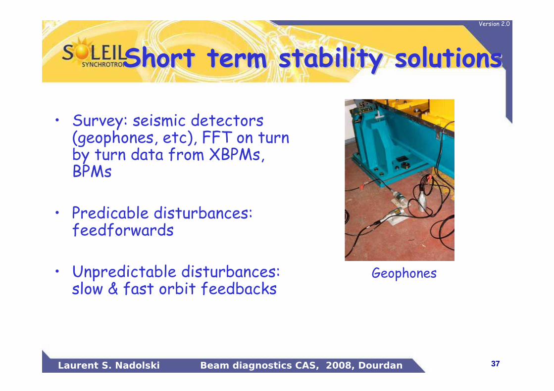
• Survey: seismic detectors (geophones, etc), FFT on turn by turn data from XBPMs, BPMs
• Predicable disturbances: feedforwards
• Unpredictable disturbances: slow & fast orbit feedbacks
Short term stability solutionsShort term stability solutions
Geophones
38Laurent S. Nadolski Beam diagnostics CAS, 2008, Dourdan
Version 2.0
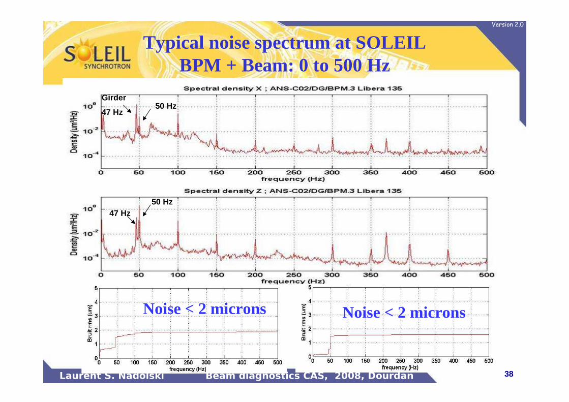
Typical noise spectrum at SOLEIL BPM + Beam: 0 to 500 Hz
Noise < 2 microns Noise < 2 microns
Girder
47 Hz50 Hz
47 Hz50 Hz
39Laurent S. Nadolski Beam diagnostics CAS, 2008, Dourdan
Version 2.0
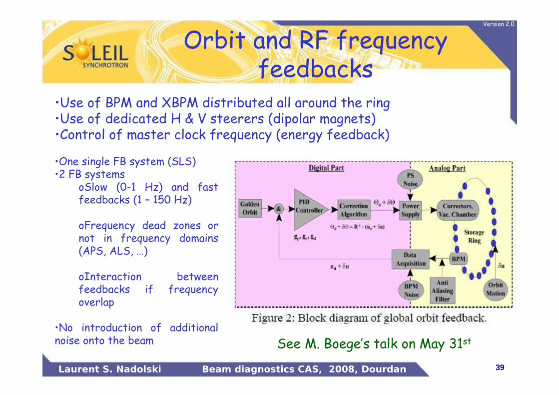
Orbit and RF frequency feedbacks
•Use of BPM and XBPM distributed all around the ring•Use of dedicated H & V steerers (dipolar magnets)•Control of master clock frequency (energy feedback)
•One single FB system (SLS)•2 FB systems
oSlow (0-1 Hz) and fast feedbacks (1 – 150 Hz)
oFrequency dead zones or not in frequency domains (APS, ALS, …)
oInteraction between feedbacks if frequency overlap
•No introduction of additional noise onto the beam See M. Boege’s talk on May 31st
40Laurent S. Nadolski Beam diagnostics CAS, 2008, Dourdan
Version 2.0
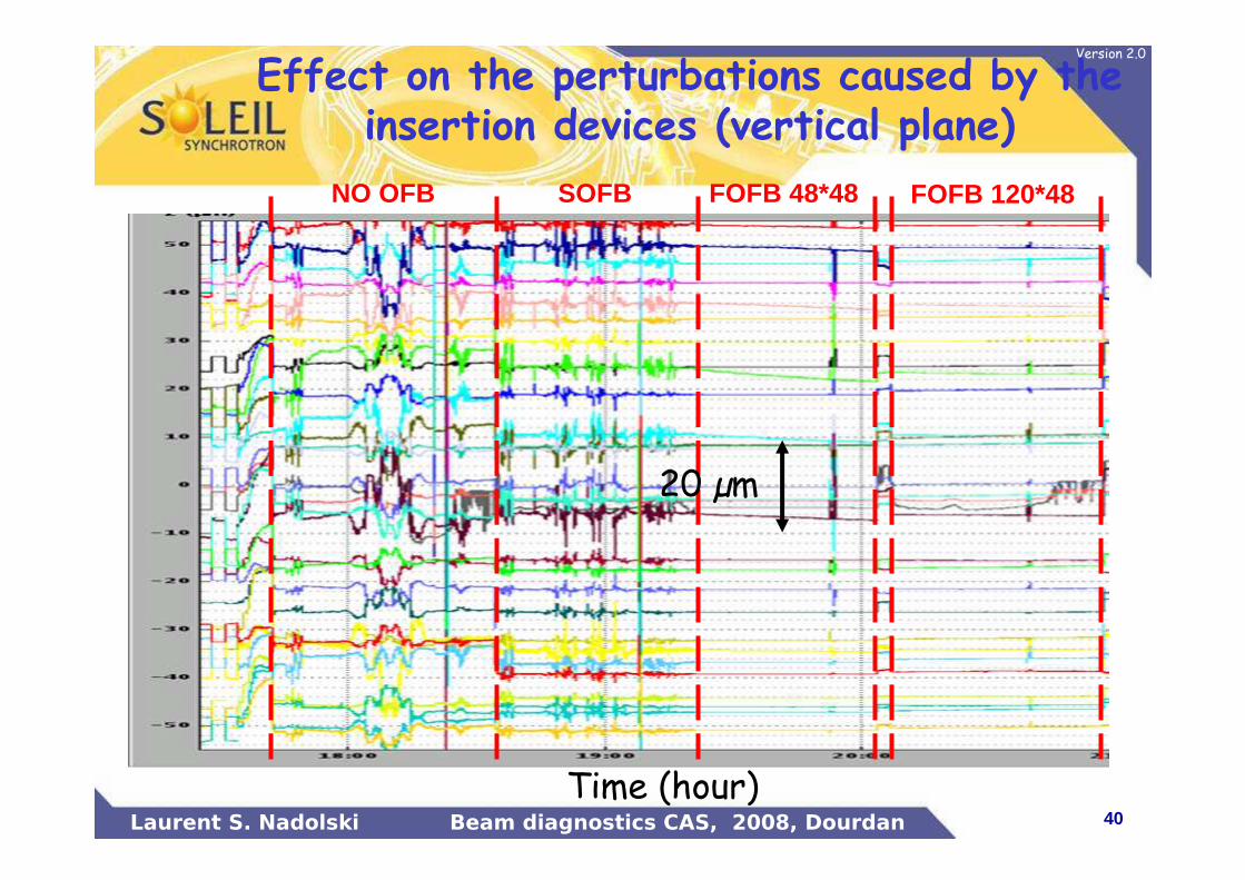
Effect on the perturbations caused by the insertion devices (vertical plane)
FOFB 48*48 FOFB 120*48SOFBNO OFB
20 µm
Time (hour)
41Laurent S. Nadolski Beam diagnostics CAS, 2008, Dourdan
Version 2.0
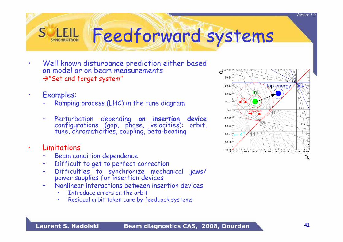
Feedforward systems• Well known disturbance prediction either based
on model or on beam measurements�”Set and forget system”
• Examples: – Ramping process (LHC) in the tune diagram
– Perturbation depending on insertion deviceconfigurations (gap, phase, velocities): orbit, tune, chromaticities, coupling, beta-beating
• Limitations– Beam condition dependence– Difficult to get to perfect correction– Difficulties to synchronize mechanical jaws/
power supplies for insertion devices– Nonlinear interactions between insertion devices
• Introduce errors on the orbit• Residual orbit taken care by feedback systems
42Laurent S. Nadolski Beam diagnostics CAS, 2008, Dourdan
Version 2.0
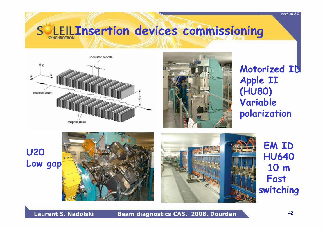
Insertion devices commissioning
EM IDHU64010 mFast
switching
U20Low gap
Motorized IDApple II (HU80)Variable polarization

43Laurent S. Nadolski Beam diagnostics CAS, 2008, Dourdan
Version 2.0
BL Name Energy Source Location Useful length (m)
PolarizationSwitch time
Periodic Technology Installation
phase 1DESIRS 5 – 40 eV HU640 I 05-L 10 Circ./lin/phasevar Yes HU640 InstalléTEMPO #1 45 – 1500 eV HU80 I 08-M 1,6 Circ./lin. QP APPLE II InstalléPROXIMA1 4 – 30 keV U20 I 10-C 1,96 Lin. Yes Hybrid in vacuum InstalléSWING 4 – 30 keV U20 I 11-C 1,96 Lin Yes Hybrid in vacuum InstalléCASSIOPEE #1 10 – 1000 eV HU256 I 15-M 3,1 Circ./lin. QP HU256 InstalléCRISTAL 4 – 30 keV U20 I 06-C 1,96 Lin Yes Hybrid in vacuum Installé
phase 2PLEIADES #2 10 – 1000 eV HU256 I 04-M 3,1 2 s QP HU256 InstalléPLEIADES #1 35 – 1500 eV HU80* I 04-M 1,6 Circ./lin. QP APPLE II InstalléANTARES #1 10 – 1000 eV HU256 I 12-M 3,1 Circ./lin. QP HU256 InstalléCASSIOPEE #2 45 – 1500 eV HU80 I 15-M 1,6 Circ./lin. QP APPLE II InstalléDEIMOS #1 500 eV – 6 keV HU52 I 07-M 1,6 Circ./lin. Yes APPLE II InstalléLUCIA 500 eV – 6 keV HU52 I 16-M 1,6 2 s ? APPLE II avr.-08SIXS 4 – 30 keV U20 I 14-C 1,96 Lin Yes Hybrid in vacuum mai-08MicroFOC #2 1 – 8 keV HU44 I 14-M 1,6 2 s APPLE II mai-08MicroFOC #1 50– 1500 eV HU80 I 14-M 1,6 Circ./lin. QP APPLE II août-08CASSIOPEE #2 100 eV – 4 keV HU60 I 15-M 1,6 2 s APPLE II août-08GALAXIES 4 – 30 keV U20 I 07-C 1,96 Lin Yes Hybrid in vacuum août-08TEMPO #2 1 – 8 keV HU44 I 08-M 1,6 2 s APPLE II sept.-08PROXIMA2 #1 5 – 15 keV U24 I 10-M 1,96 Lin. Yes Hybrid in vacuum janv.-09SIRIUS 2 – 10 keV HU34 I 15-C 1,6 2 – 4 keV Yes APPLE II janv.-09ANTARES #2 100 eV – 4 keV HU60 I 12-M 1,6 2 s APPLE II mars-09DEIMOS #2 350 – 900 eV HU65 I 07-M 1,6 0,2 s/ 5Hz-10Hz Yes EMPHU avr.-09MicroXmou 100 eV – 4 keV HU60 ? I 06-M 1,6 Circ./lin. QP APPLE II mai-09HT PRESSION 10 – 50 keV WSV50 I 03-C 2,0 Lin Yes Wiggler in vacuum juil.-09MicroScopium 4 – 30 keV U20 ? I 02-C 1,96 Lin. Yes Hybrid in vacuum janv.-10
Insertion device based rings
44Laurent S. Nadolski Beam diagnostics CAS, 2008, Dourdan
Version 2.0
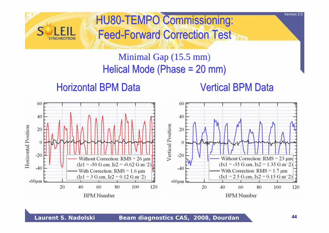
HU80HU80--TEMPO Commissioning: TEMPO Commissioning:
FeedFeed--Forward Correction TestForward Correction Test
Minimal Gap (15.5 mmMinimal Gap (15.5 mm))
Helical Mode (Phase = 20 mm)Helical Mode (Phase = 20 mm)
Horizontal BPM DataHorizontal BPM Data Vertical BPM DataVertical BPM Data
45Laurent S. Nadolski Beam diagnostics CAS, 2008, Dourdan
Version 2.0
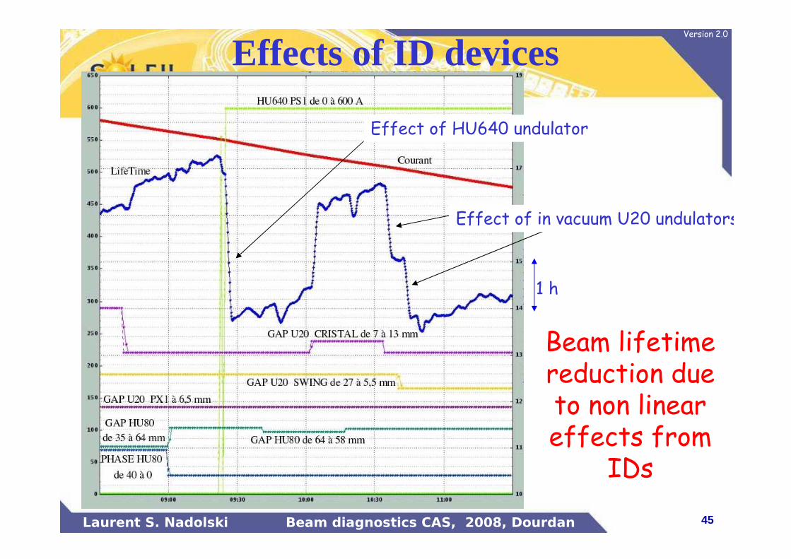
Effect of HU640 undulator
1 h
Effect of in vacuum U20 undulators
Effects of ID devices
Beam lifetime reduction due to non linear effects from
IDs
46Laurent S. Nadolski Beam diagnostics CAS, 2008, Dourdan
Version 2.0
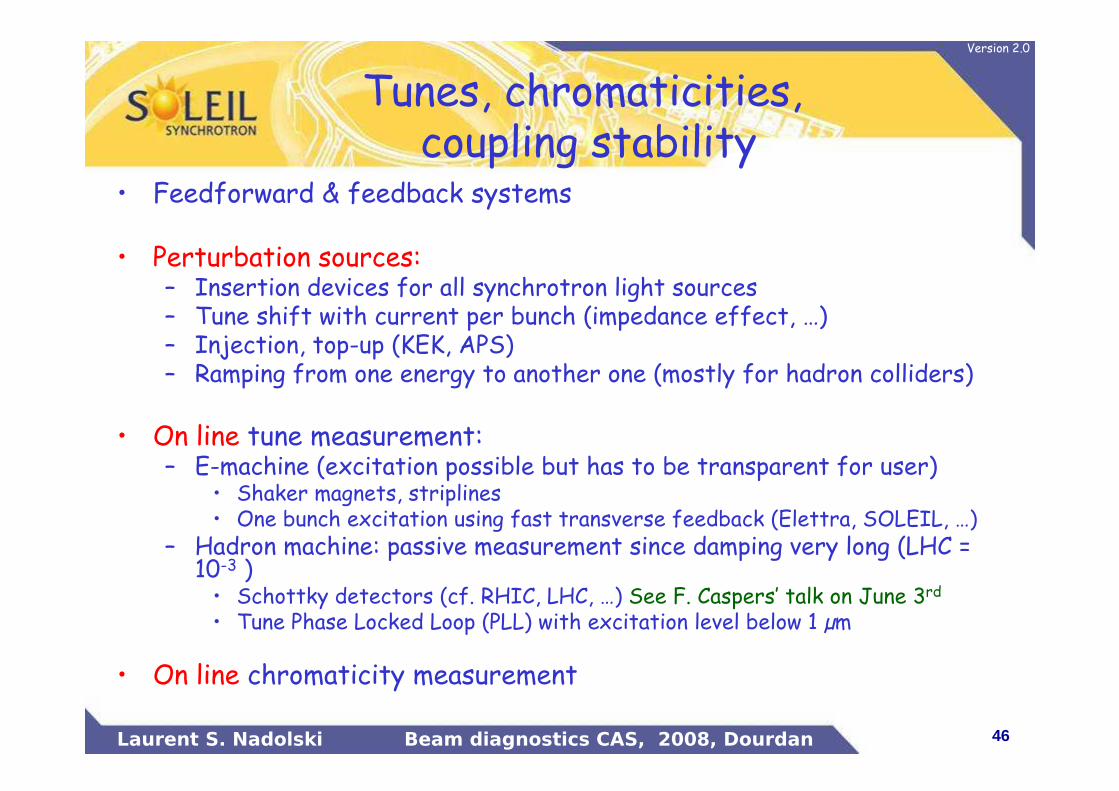
Tunes, chromaticities, coupling stability
• Feedforward & feedback systems
• Perturbation sources:– Insertion devices for all synchrotron light sources– Tune shift with current per bunch (impedance effect, …)– Injection, top-up (KEK, APS)– Ramping from one energy to another one (mostly for hadron colliders)
• On line tune measurement:– E-machine (excitation possible but has to be transparent for user)
• Shaker magnets, striplines• One bunch excitation using fast transverse feedback (Elettra, SOLEIL, …)
– Hadron machine: passive measurement since damping very long (LHC = 10-3 )• Schottky detectors (cf. RHIC, LHC, …) See F. Caspers’ talk on June 3rd
• Tune Phase Locked Loop (PLL) with excitation level below 1 µm
• On line chromaticity measurement
47Laurent S. Nadolski Beam diagnostics CAS, 2008, Dourdan
Version 2.0
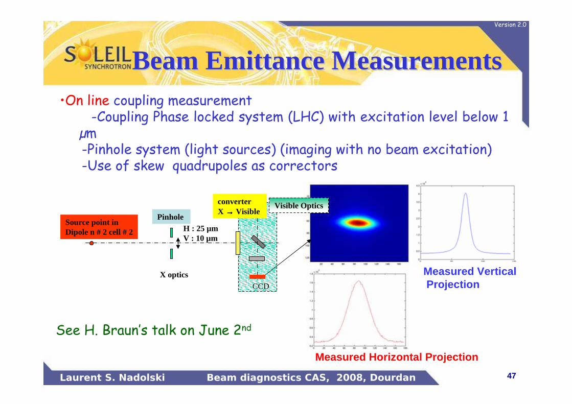
Measured Horizontal Projection
Measured VerticalProjection
Visible OpticsconverterX →→→→ Visible
H : 25 µmV : 10 µm
PinholeSource point inDipole n # 2 cell # 2
CCD
X optics
See H. Braun’s talk on June 2nd
•On line coupling measurement-Coupling Phase locked system (LHC) with excitation level below 1
µm-Pinhole system (light sources) (imaging with no beam excitation)-Use of skew quadrupoles as correctors
Beam Emittance MeasurementsBeam Emittance Measurements
48Laurent S. Nadolski Beam diagnostics CAS, 2008, Dourdan
Version 2.0
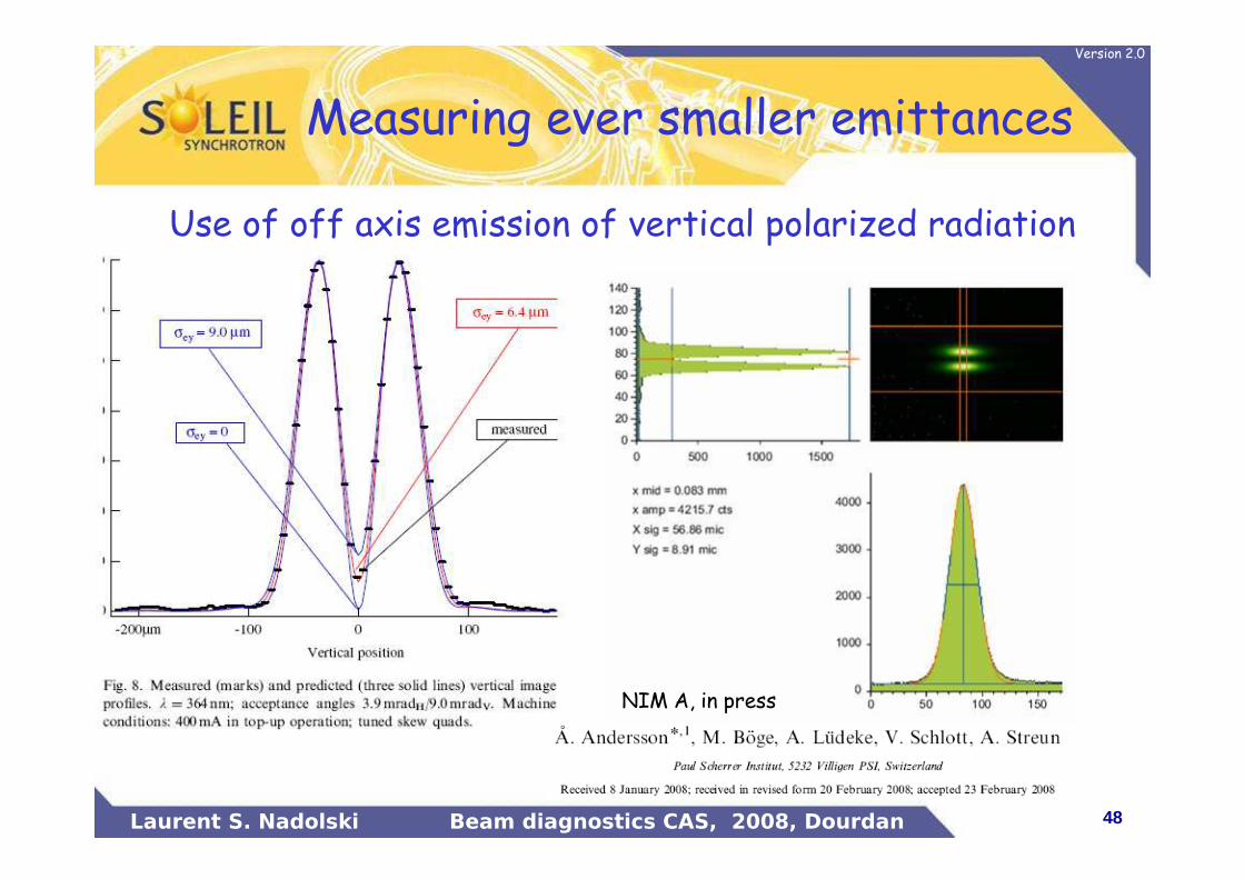
Measuring ever smaller emittances
NIM A, in press
Use of off axis emission of vertical polarized radiation
49Laurent S. Nadolski Beam diagnostics CAS, 2008, Dourdan
Version 2.0
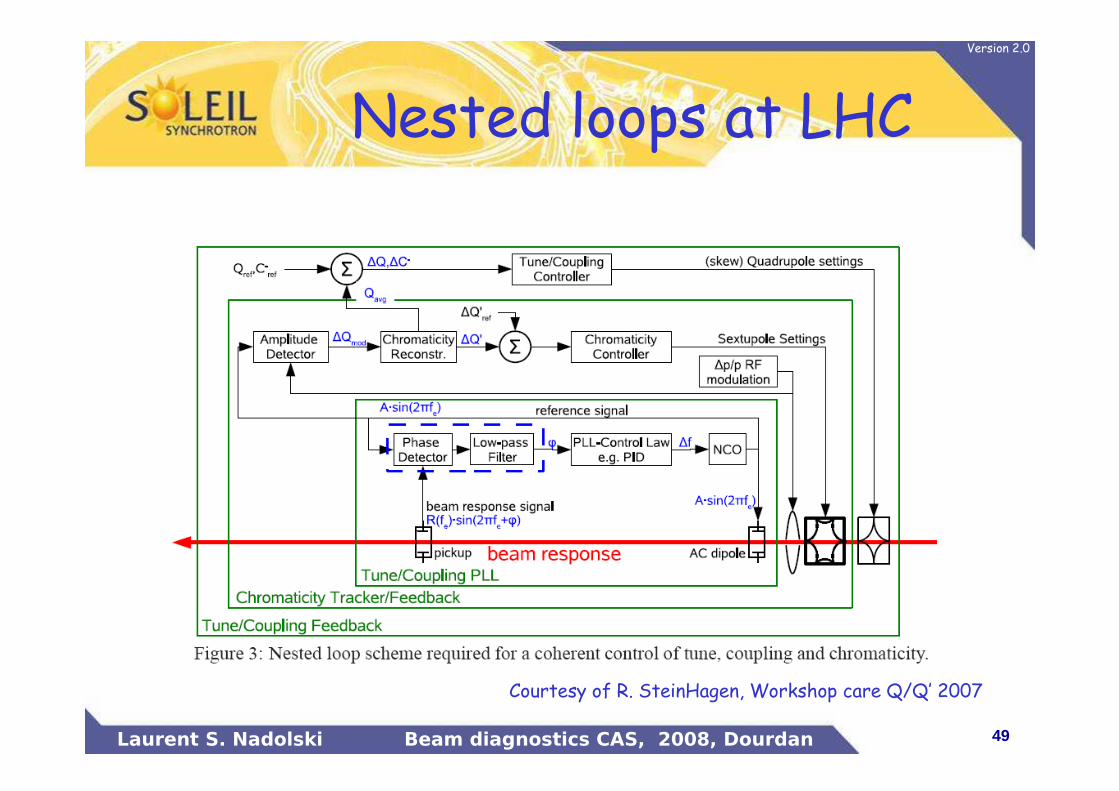
Nested loops at LHC
Courtesy of R. SteinHagen, Workshop care Q/Q’ 2007
50Laurent S. Nadolski Beam diagnostics CAS, 2008, Dourdan
Version 2.0
Collective effects: difficult part
• Interaction of the beam with the vacuum vessel (wake fields, impedance), with the residual gas– Trigger instability in transverse and longitudinal planes– Trigger single bunch and multi-bunch instabilities – Need of dedicated feedbacks, designs, …
• High density of current per bunch induces– Bunch lengthening– Instabilities (microwave, …) � current threshold
�Bunch length measurement (streak camera, …)
• Beam/beam effect in colliders
• CSR effects and instabilities, beam break-up, …
See M. Lonza’s talk on June 4th
51Laurent S. Nadolski Beam diagnostics CAS, 2008, Dourdan
Version 2.0
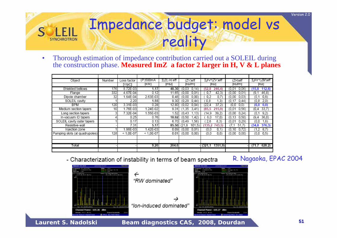
Impedance budget: model vsreality
• Thorough estimation of impedance contribution carried out a SOLEIL during the construction phase. Measured ImZ a factor 2 larger in H, V & L planes
R. Nagaoka, EPAC 2004
52Laurent S. Nadolski Beam diagnostics CAS, 2008, Dourdan
Version 2.0
Daily operationAim: high beam availability, save operation and steady high
performances
• Survey of the beam parameters (closed orbit, tunes, chromaticities, coupling, current decay, luminosity, injection efficiency, instabilities)
• Top-up operation for Light sources• Dose rate• Capacity to control and localize beam losses
– Mandatory for large energy machine (cf. LHC, loosing the beam isforbidden)• Too much energy stored into the beam will quench magnets and/or destroy equipments
• Activation of components, areas• Radiation safety issue
– Machine Protection system See R. Schmidt’s talk on June 5th• Thermocouple, Instabilities slot, Beam position, Pressure …• Limit maximum current stored into the accelerator• Beam dumpers
53Laurent S. Nadolski Beam diagnostics CAS, 2008, Dourdan
Version 2.0
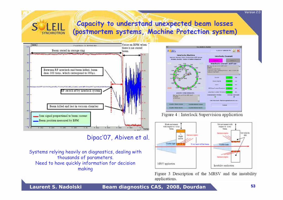
Capacity to understand unexpected beam losses (postmortem systems, Machine Protection system)
Dipac’07, Abiven et al.
Systems relying heavily on diagnostics, dealing with thousands of parameters.
Need to have quickly information for decision making

54Laurent S. Nadolski Beam diagnostics CAS, 2008, Dourdan
Version 2.0
Conclusion• Model/Reality: a lots of improvements this last 10 years, nevertheless:
– Difficulties to foresee all aspects– Static errors (modeled in a statistical way: impossible to get the real
distribution)– Dynamical errors
• High number of perturbation sources– Known sources– Unknown sources
• By pushing so much accelerator performance, parameters become very sensitive to any drift in temperature, in tunes, …
• High performance can be reached only with the heavy help of lots of feedforward and feedback systems.
Fortunately, high performance diagnostics enable us to get a model close to reality
Diagnostics improvements help us to increase performance
55Laurent S. Nadolski Beam diagnostics CAS, 2008, Dourdan
Version 2.0
Acknowledgments
• A. Nadji (SOLEIL)
• J.C. Denard (SOLEIL)
• P. Brunelle (SOLEIL)
• R. Steinhagen (LHC)
• V. Schlott (PSI)
• W. Decking (DESY)
• H. Braun (CERN)


![Multiband Transceivers - [Chapter 2] Noises and Linearities](https://img.dokumen.tips/doc/110x75/55cf0420bb61ebb0078b482e/multiband-transceivers-chapter-2-noises-and-linearities.jpg)