Embed Size (px)
Citation preview
Better Lightning Protection
with
Insulation, Arresters & Grounds_________________________________________________________________________________________________________________
PowerStream’s FindingsPresentation at
EDIST 2017, Engineering Track A6
Joe Crozier, Standards Engineer, PowerStream
2017.01.19
1

Presentation abstract
Lightning is a major cause of distribution system
outages. With annual ground strikes expected to
increase fifty per cent by 2100, utilities need
effective, economic mitigation measures. A recent
lightning protection study at PowerStream
identified 30 industry best practices, most of them
involving better insulation, arresters and grounds.
These are summarized, along with expected
improvement based on experience at
PowerStream and elsewhere.
2

Presentation outline
1. Lightning W5
2. Circuit model
3. Grounds
4. Arresters
5. Insulation
6. Q&A
3
They helped!
Dave Burns Lori Gallaugher Bill Chisholm
PowerStream Utilities Standards Kinectrics
Forum
4
IEEE Std 1410-2010
5
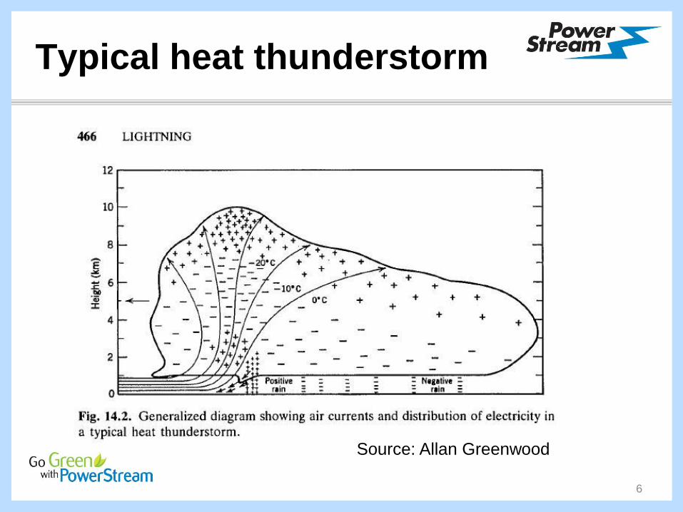
Typical heat thunderstorm
6
Source: Allan Greenwood

Slo-mo lightning flash
7
Source: Allan Greenwood
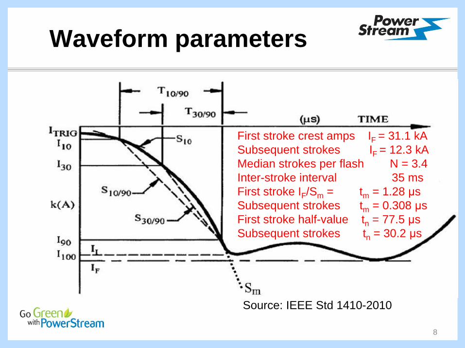
Waveform parameters
8
Source: IEEE Std 1410-2010
First stroke crest amps IF = 31.1 kA
Subsequent strokes IF = 12.3 kA
Median strokes per flash N = 3.4
Inter-stroke interval 35 ms
First stroke IF/Sm = tm = 1.28 μs
Subsequent strokes tm = 0.308 μs
First stroke half-value tn = 77.5 μs
Subsequent strokes tn = 30.2 μs
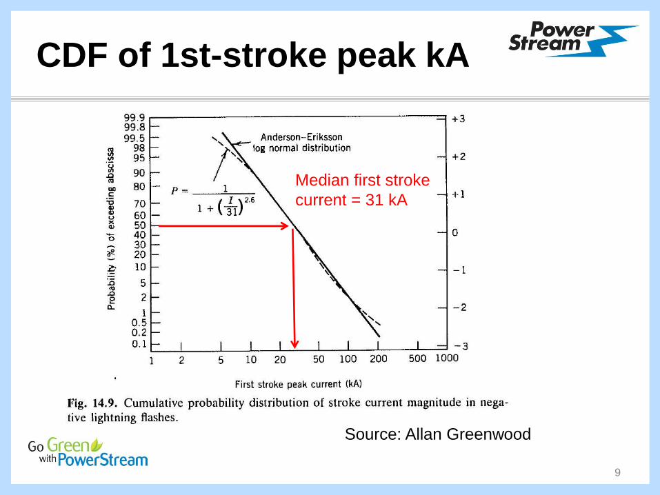
CDF of 1st-stroke peak kA
9
Source: Allan Greenwood
Median first stroke
current = 31 kA
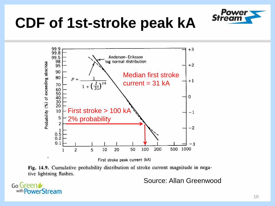
CDF of 1st-stroke peak kA
10
Source: Allan Greenwood
Median first stroke
current = 31 kA
First stroke > 100 kA
2% probability

Lightning, Canada West
11
Source: Environment Canada

Lightning, Ontario
12
Source: Environment Canada

Lightning, Southern Ont.
13
Source: Environment Canada
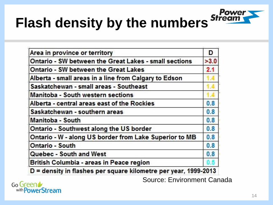
Flash density by the numbers
14
Source: Environment Canada

“STRUCK BY LIGHTNING”
“The temperature of the electrical arc can reach 30,000
degrees Celsius … When lightning hits the ground, in most
cases it will be on an elevated point, such as the top of a
mountain, a high-rise structure, a component of an electric
distribution network, etc … When lightning directly strikes on
an electric distribution network, it inevitably generates
devastating consequences … network power distribution
equipment can be damaged … most of the regular protection
mechanisms will not be able to withstand the power generated
by the electrical discharge of a lightning strike”
15
Source: David Savard, CEP

Global warming & lightning
“Lightning plays an important role in atmospheric chemistry …
we propose that … flash rate is proportional to the convective
available potential energy (CAPE) times the precipitation rate.
Using observations, the product of CAPE and precipitation
explains 77% of the variance in the time series of total cloud-
to-ground lightning flashes over the contiguous United States
(CONUS). Storms convert CAPE times precipitated water
mass to discharged lightning energy with an efficiency of 1%.
When … applied to 11 climate models, CONUS lightning strikes are predicted to increase 12 ±5% per degree Celsius
of global warming and about 50% over this century.”
16
Source: Science, 14 Nov 2014

Lightning W5
• Median first stroke 30 kA but can exceed 100 kA
• Microsecond event times (BIL wave 1.2 x 50 μs)
• 2.34 million flashes/year in Canada, about once
every three seconds during the summer months
• Hot spots southwest and southcentral ON
southwest MB & southeast SK
central AB east of Rockies
northeast BC (Peace region)
• Possible 50% increase in flash density by 2100
17
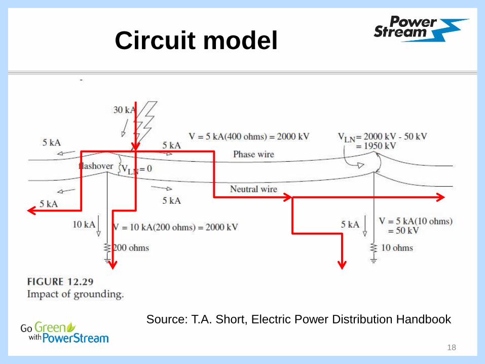
Circuit model
18
Source: T.A. Short, Electric Power Distribution Handbook

Circuit model
19
Source: T.A. Short, Electric Power Distribution Handbook
400 ohms surge impedance
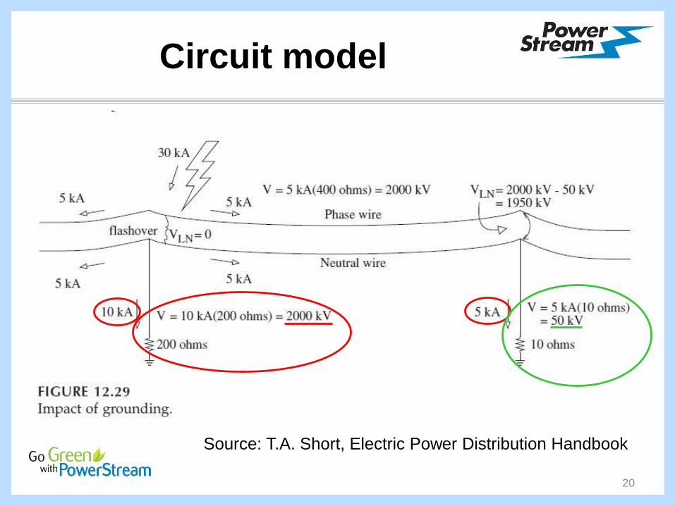
Circuit model
20
Source: T.A. Short, Electric Power Distribution Handbook

Circuit model
21
Source: T.A. Short, Electric Power Distribution Handbook
1. Pole ground resistance
2. Lightning
arresters3. Insulation
Pole ground resistance
O.C. Seevers, P.E. wrote several electrical
engineering books based on his experience at
Kentucky Utilities from 1947 to 1991:
• “Wherever we have had repeated lightning
damage we have found high resistance
measurements to ground. Wherever we have
improved those grounds to near zero, the
lightning damage has ceased.”
22
Source: O.C. Seevers, Power Systems Handbook

Pole ground resistance
• “About 8 years ago, I started a program of
testing and improving all grounds on equipment
poles in rural areas, by contractor. About half of
my territory is on limestone. The rest has sandy,
clay-type soil. If the ground measures over 10
ohms, we add a rod, and re-measure. If still over
10 ohms, we add one more rod and then give
up.”
23
Source: O.C. Seevers, P.E., Power Systems Handbook

Pole ground resistance
• “ … in the areas we have covered, our expense
due to lightning damage has been reduced to
one-fifth of the cost before grounding. I set out
to cover my division in ten years. The savings
each year have more than paid for the annual
program cost. When you consider that the
savings will continue forever and the costs will
cease two years from now, you get some feel for
the enormous benefit we will reap on out into the
future.”
24
Source: O.C. Seevers, P.E., Power Systems Handbook
Pole ground resistance
• “We have installed arresters on long distribution
lines where lightning damage was a regular
visitation. We installed them every few miles
and made sure the grounds were good
(emphasis added – JC). The trouble just
stopped. No more trouble at all.”
25
Source: O.C. Seevers, P.E., Power Systems Handbook
Pole ground resistance
• Seevers’s experience supports 10 Ω as standard
• The common industry standard is 25 Ω
• Q: is 25 Ω an adequate, ‘good enough’ target?
• Q: would 10 Ω be too stringent? uneconomic?
• Lori Gallaugher (executive director, USF) asked
John O’Neill (project manager, CSA std. C22.3)
• Apparently no engineering studies support 25 Ω
as an adequate standard for ground resistance
26
Source: Lori Gallaugher and John O’Neill, July 9, 2015

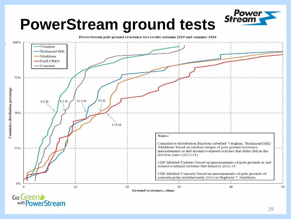
PowerStream ground tests
• Measured ground Ω near all pole-mounted LISs
and ScadaMates in Markham, Richmond Hill &
Vaughan that failed from 2012 to 2015.
• For each of the three municipalities, picked a
representative control sample of poles in the
vicinity of switches that didn’t fail 2012-15. Used
stratified/cluster random sampling to ensure the
conclusions we drew from the data were valid.
• Analysis, conclusions, recommendations
27
Source: PowerStream

PowerStream ground tests
• Used AEMC model 3700 clamp-on ground
resistance tester for all tests.
• Verified accuracy by measuring several pole
down-grounds using clamp-on testers from two
other manufacturers, Fluke and Megger. The
three manufacturers’ testers yielded results
within 3% of one another for readings up to 10Ω
and within 11% for readings up to 100Ω –
considered accurate enough for our purposes
28
Source: PowerStream
PowerStream ground tests
29
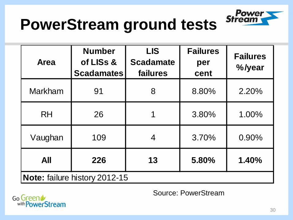
PowerStream ground tests
30
Source: PowerStream
Markham 91 8 8.80% 2.20%
RH 26 1 3.80% 1.00%
Vaughan 109 4 3.70% 0.90%
All 226 13 5.80% 1.40%
Area
LIS
Scadamate
failures
Number
of LISs &
Scadamates
Failures
per
cent
Failures
%/year
Note: failure history 2012-15
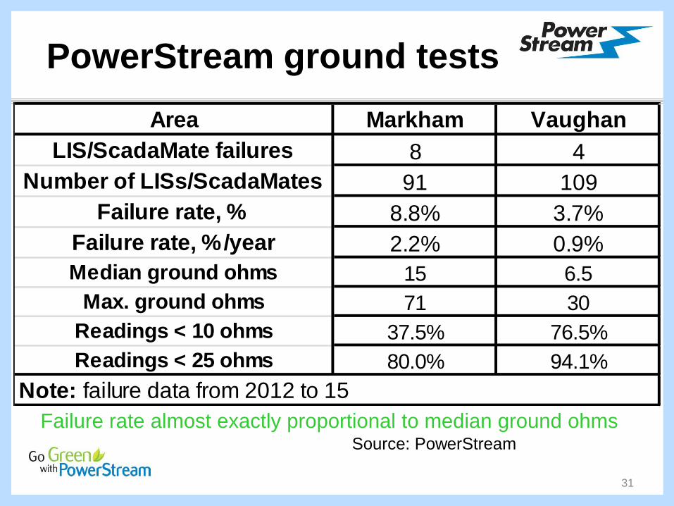
PowerStream ground tests
Failure rate almost exactly proportional to median ground ohms
31
Source: PowerStream
Area Markham Vaughan
LIS/ScadaMate failures 8 4
Number of LISs/ScadaMates 91 109
Failure rate, % 8.8% 3.7%
Failure rate, %/year 2.2% 0.9%
Median ground ohms 15 6.5
Max. ground ohms 71 30
Readings < 10 ohms 37.5% 76.5%
Readings < 25 ohms 80.0% 94.1%
Note: failure data from 2012 to 15

PowerStream ground tests
• Despite our small sample size, our results at
PowerStream appear consistent with Seevers’s
• Despite the encouraging concrete pole ground
resistance results, we don’t yet know if a 10 Ω
standard is economic on all equipment poles
• Costliest replacements – automated switches
Recommendation:
• Max. 10 Ω ground on all automated switches
32
Source: PowerStream
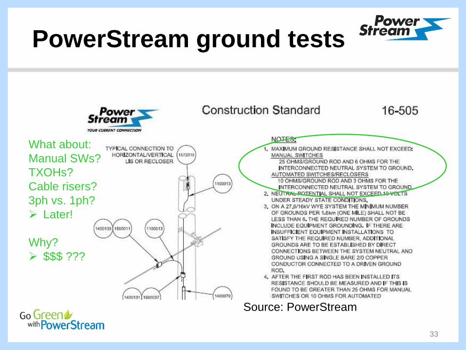
PowerStream ground tests
33
Source: PowerStream
What about:
Manual SWs?
TXOHs?
Cable risers?
3ph vs. 1ph?
Later!
Why?
$$$ ???
Arresters
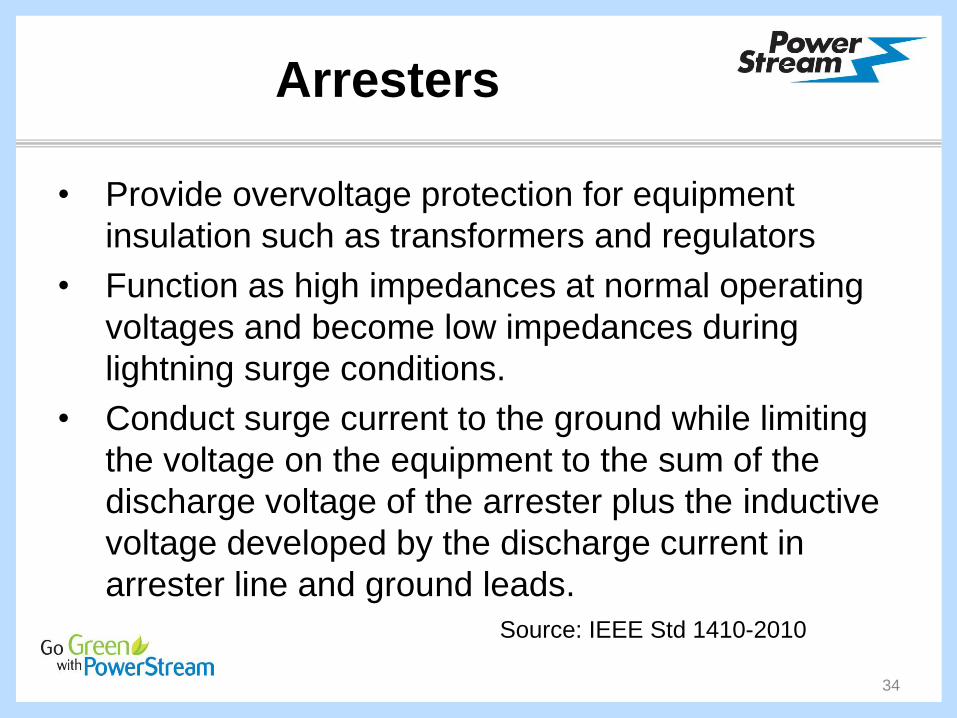
• Provide overvoltage protection for equipment
insulation such as transformers and regulators
• Function as high impedances at normal operating
voltages and become low impedances during
lightning surge conditions.
• Conduct surge current to the ground while limiting
the voltage on the equipment to the sum of the
discharge voltage of the arrester plus the inductive
voltage developed by the discharge current in
arrester line and ground leads.
34
Source: IEEE Std 1410-2010

Arresters
• asdf
35
Source: T.A. Short, Electric Power Distribution Handbook

Arresters
• asdf
36
Source: IEEE Std 1410-2010
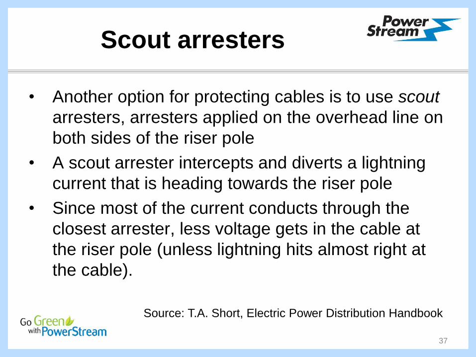
Scout arresters
• Another option for protecting cables is to use scout
arresters, arresters applied on the overhead line on
both sides of the riser pole
• A scout arrester intercepts and diverts a lightning
current that is heading towards the riser pole
• Since most of the current conducts through the
closest arrester, less voltage gets in the cable at
the riser pole (unless lightning hits almost right at
the cable).
37
Source: T.A. Short, Electric Power Distribution Handbook

Scout arresters
Scout arrester effectiveness depends on grounding the scout
arresters well. Without good grounding, the ground potential
rises at the scout arrester, causing high voltage on the phase
and neutral wire (but little voltage difference between them).
When the surge arrives at the riser pole, the low impedance
ground path offered by the cable drops the neutral potential
(and increases the phase-to-neutral voltage). This pulls
significant current through the riser-pole arrester (and sends a
voltage wave down the cable), which reduces the
effectiveness of the scout arresters. The lower the impedance
of the scout arrester grounds, the less this effect occurs.
38
Source: T.A. Short, Electric Power Distribution Handbook

Scout arresters
39

Scout arresters
40
What about:
Manual SWs?
TXOHs?
Cable risers?
3ph vs. 1ph?
Later!
Why?
$$$ ???

Insulators
41
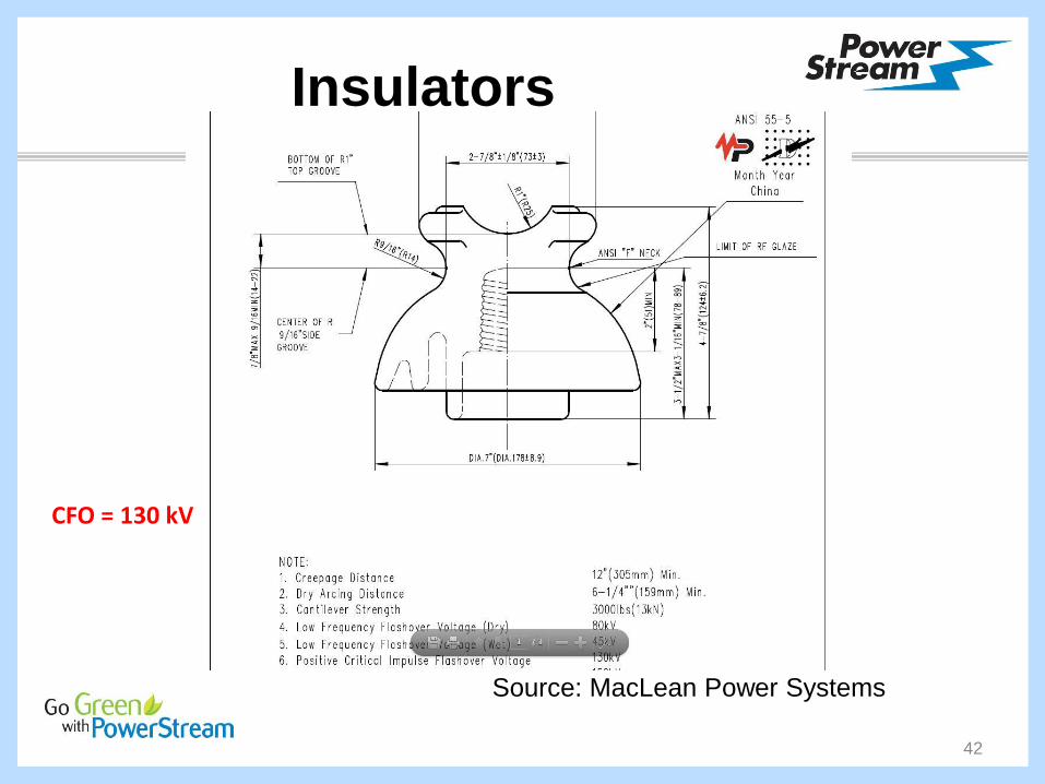
3.4 critical impulse flashover
voltage (CFO) (insulators): The
crest value of the impulse wave that,
under specified conditions, causes
flashover through the surrounding
medium on 50% of the applications.
Source: IEEE Std 1410-2010S
Insulators
42
Source: MacLean Power Systems
CFO = 130 kV

Insulators
43
CFO = 200 kV
Source: MacLean Power Systems

Insulators
44
Source: K-Line Insulators
15 kV
CFO = 130 kV
46 kV
CFO =
130 kV
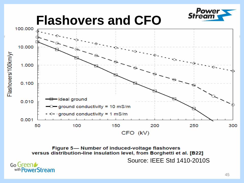
Flashovers and CFO
45
Source: IEEE Std 1410-2010S

Flashovers & Sparkovers
46
• A flashover involves a surface. Thus, if a surge causes
a spark to propagate across the surface of a bushing [or
an insulator], it would be a flashover.
• A sparkover occurs across a gap. It may be, for
instance, across a protective rod gap. [Or between
rebar and bolts]
• Why is this distinction important?
Wood poles can contribute significantly to the CFO of
the entire insulation path from primary to ground
Concrete poles contribute a CFO of 0 kV!
Source: Allan Greenwood
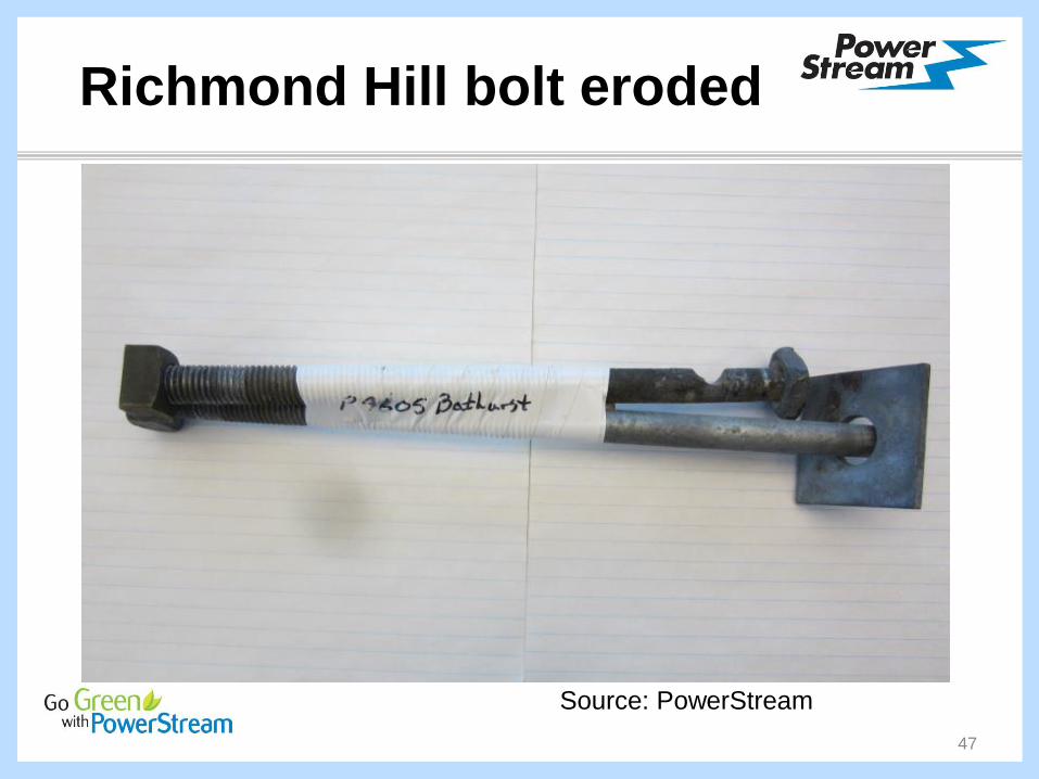
Richmond Hill bolt eroded
47
Source: PowerStream

Richmond Hill bolt eroded
48
Source: PowerStream
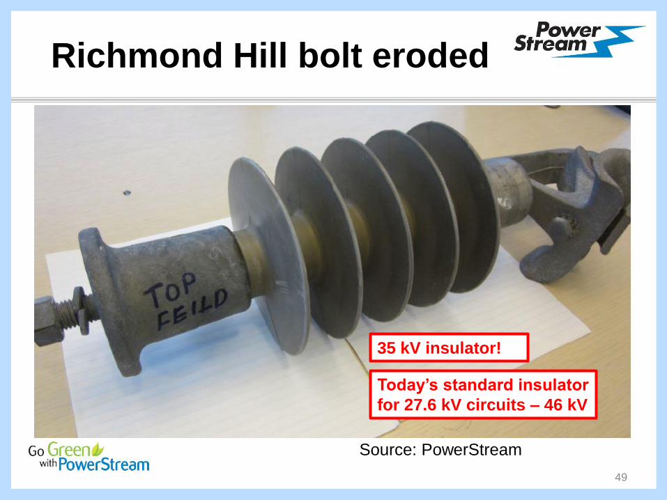
Richmond Hill bolt eroded
49
Source: PowerStream
35 kV insulator!
Today’s standard insulator
for 27.6 kV circuits – 46 kV

Markham concrete pole pilot
50
Source: PowerStream
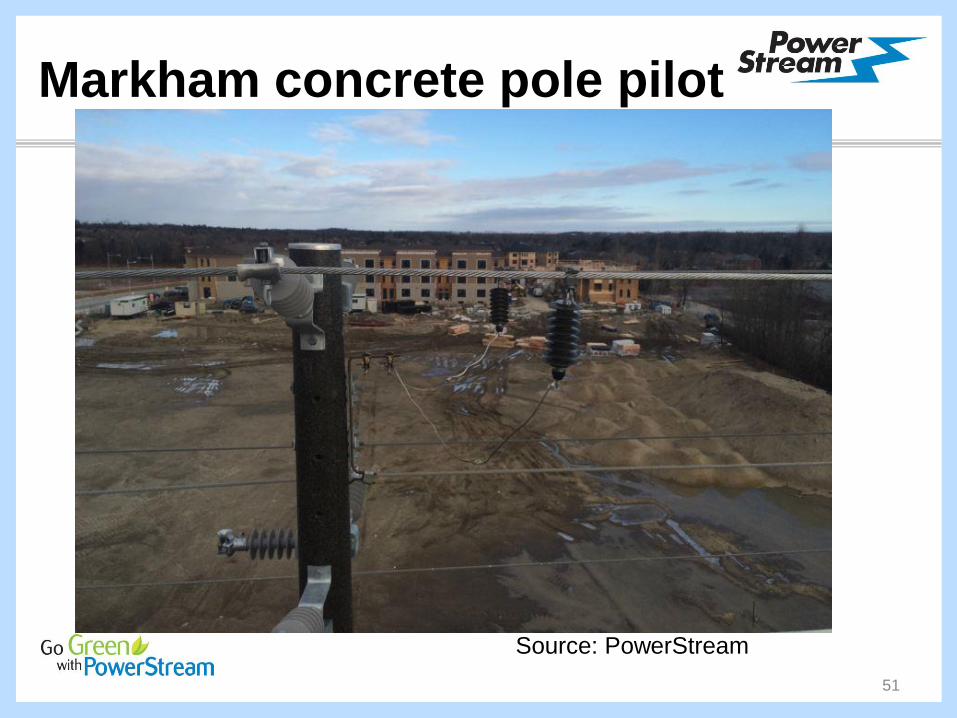
Markham concrete pole pilot
51
Source: PowerStream

Markham concrete pole pilot
52
Source: PowerStream

Flashovers and CFO
53
Source: IEEE Std 1410-2010S
Ideal ground
100 Ω·m ground

Presentation summary
1. Lightning W5: flashes/(km2·yr) ↑
2. Circuit model: simple, not simplistic
3. Grounds: auto switches: 25 Ω 10 Ω
4. Arresters: scouts on auto switches
5. Insulation: 46 kV KLI on 27.6 kV ccts
6. Q&A
54