Embed Size (px)
Citation preview

Betriebsanleitung
Watt-Drive MAS® - Getriebe und Getriebemotoren
LABA-WDMAS-0117

Montageanleitung inklusive Hinweise zu Betrieb und Wartung
Mounting Instruction Information about operation and maintenance is included
MAS® - Getriebe und Getriebemotoren MAS® - Gear units and geared motors
ATEX included
BA27 MAS, ATEX 01/2017 Deutsch – English Originaldokument: Deutsch Original documentation: German

Montageanleitung für MAS® - Getriebe und Getriebemotoren Mounting Instruction for MAS® - Gear units and geared motors
Watt Drive Antriebstechnik GmbH ·A-2753 Markt Piesting ·Wöllersdorfer Str. 68 ·Phone: +43(0)2633 404-0 · Fax: +43(0)2633 404-220 · Mail: [email protected] · Web: www.wattdrive.com 2
Inhaltsverzeichnis / Contents 1 Allgemeines / General ................................................................................................................................................................ 4
Sicherheits- und Hinweiszeichen / Safety and information markings ................................................................................... 4
Allgemeine Informationen / General information .................................................................................................................. 4
Haftungsausschluss / Exclusion of liability ........................................................................................................................... 5
Hinweis auf Urheber und Schutzrecht / Indication of copyright and protective right ............................................................. 5
2 Allgemeine Sicherheit / General safety .................................................................................................................................... 6 3 Beschreibung des Getriebes, Getriebemotors / Gear unit, Geared motor description ........................................................ 7
Typenschild / Nameplate ...................................................................................................................................................... 7
Typenbezeichnung / Type designation ................................................................................................................................. 7
4 Transport .................................................................................................................................................................................. 10 5 Lagerung / Storage .................................................................................................................................................................. 11 6 Getriebeaufbau / Gear unit construction ............................................................................................................................... 12
Prinzipieller Aufbau – Stirnradgetriebe H / Basic design principles helical gear unit H ...................................................... 12
Prinzipieller Aufbau – Aufsteckgetriebe A / Basic design principles shaft mounted gear unit A ......................................... 13
Prinzipieller Aufbau – Flachgetriebe F / Basic design principles parallel shaft gear unit F ................................................. 14
Prinzipieller Aufbau - Schneckengetriebe S / Basic design principles helical worm gear unit S ......................................... 15
Prinzipieller Aufbau – Kegelstirnradgetriebe K / Basic design principles helical bevel gear unit K ..................................... 16
Prinzipieller Aufbau – Kegelflachgetriebe C / Basic design principles angle parallel shaft gear unit C .............................. 17
7 Mechanische Installation / Mechanical installation ............................................................................................................... 18 Vorarbeiten Getriebe / Preparatory work gear unit ............................................................................................................. 18
Vorarbeiten Motor / Preparatory work motor ...................................................................................................................... 19
Aufstellen des Getriebes, Getriebemotors / Setting up the gear unit, geared motor .......................................................... 21
8 Checkliste – Getriebe / Check list – Gear unit ....................................................................................................................... 33 9 Checkliste – Motor / Check list – Motor ................................................................................................................................. 34 10 Inbetriebnahme / Startup ......................................................................................................................................................... 35
Elektrischer Anschluss des Motor / Electrical connecting the motor .................................................................................. 35
Drehrichtung / Direction of rotation ..................................................................................................................................... 35
Ölstand des gelieferten Getriebes / Oil level in the gear unit as delivered ......................................................................... 35
11 Betrieb / Operation ................................................................................................................................................................... 36 12 Betriebsstörungen / Malfunction ............................................................................................................................................ 36 13 Inspektion und Wartung / Inspection and maintenance ....................................................................................................... 37
Inspektions- und Wartungsintervalle / Inspection and maintenance intervals .................................................................... 38
Inspektions- und Wartungsarbeiten Getriebe / Inspection and maintenance work on gear unit ......................................... 39
14 Schmierstoffe / Lubricants ...................................................................................................................................................... 41 15 Bauformen und Schmierstoffmengen / Mounting positions and lubricant capacity ......................................................... 42
Stirnradgetriebe H / Helical gear units H ............................................................................................................................ 42
Einstufige Stirnradgetriebe H / Single stage helical gear units H ....................................................................................... 43
Aufsteckgetriebe A / Shaft mounted gear units A ............................................................................................................... 44
Flachgetriebe F / Parallel shaft gear units F ....................................................................................................................... 45
Kegelstirnradgetriebe K40 - K75 / Helical bevel gear units K40 - K75 ............................................................................... 46
Kegelstirnradgetriebe K77 - K139 / Helical bevel gear units K77 - K139 ........................................................................... 47
Stirnradschneckengetriebe S / Helical worm gear units S .................................................................................................. 48
Kegelflachgetriebe C / Angle parallel shaft gear units C .................................................................................................... 49

Montageanleitung für MAS® - Getriebe und Getriebemotoren Mounting Instruction for MAS® - Gear units and geared motors
Watt Drive Antriebstechnik GmbH ·A-2753 Markt Piesting ·Wöllersdorfer Str. 68 ·Phone: +43(0)2633 404-0 · Fax: +43(0)2633 404-220 · Mail: [email protected] · Web: www.wattdrive.com 3
Ölstandskontrolle bei Getrieben mit Ölstandsschraube in vertikaler Bauform / Oil level control of gear units with oil level plug at vertical mounting position ......................................................................................................................................... 50
16 Klemmenanschluss / Terminal board connection ................................................................................................................. 51 17 Optionale Motorzusatzeinrichtungen / Optional motor devices .......................................................................................... 53
Stillstandsheizung / Anti-condensation heating .................................................................................................................. 53
Kondenswasserbohrung / Drain ......................................................................................................................................... 53
Fremdlüfter / Forced cooling .............................................................................................................................................. 54
Temperaturwächter Bimetallschalter “Öffner” (TH) / Temperature controller Bimetal switch “NC contact” (TH) ................ 54
PTC Kaltleitertemperaturfühler (TF) / PTC Thermistor protection (TF) .............................................................................. 54
Bremse / Brake .................................................................................................................................................................. 55
Drehgeber / Encoder .......................................................................................................................................................... 58
18 Tabelle für Schraubenanzugsmomente / Table of Tightening Torques .............................................................................. 59 19 Entsorgung / Disposal ............................................................................................................................................................. 59 20 Einbauerklärung / Declaration of Incorporation .................................................................................................................... 61 21 EU-Konformitätserklärung ATEX 2014/34/EU / EU Declaration of Conformity ATEX 2014/34/EU ..................................... 63 22 EU-Konformitätserklärung Niederspannungsrichtlinie 2014/35/EU / EU-Declaration of Conformity Low Voltage
Directive 2014/35/EU ................................................................................................................................................................ 65

Montageanleitung für MAS® - Getriebe und Getriebemotoren Mounting Instruction for MAS® - Gear units and geared motors
Watt Drive Antriebstechnik GmbH ·A-2753 Markt Piesting ·Wöllersdorfer Str. 68 ·Phone: +43(0)2633 404-0 · Fax: +43(0)2633 404-220 · Mail: [email protected] · Web: www.wattdrive.com 4
1 Allgemeines / General
Sicherheits- und Hinweiszeichen / Safety and information markings
Diese Sicherheits- und Warnhinweise sind unbedingt zu beachten!
GEFAHR ! Warnung vor elektrischer oder mechanischer Gefahr.
ATEX ! Wichtige Hinweise zum Explosionsschutz.
VORSICHT ! Wichtige Anweisung für sicheren und störungsfreien Betrieb.
All safety and warning instructions must be followed without exception!
WARNING ! Warning of electrical or mechanical danger.
ATEX ! Important information on explosion protection.
ATTENTION ! Important instructions for safe and trouble-free operation.
Allgemeine Informationen / General information
Die vorliegende Montageanleitung (MA) ist Bestandteil der Getriebelieferung und muss bevor Sie mit dem Getriebe arbeiten gelesen werden. Die Anweisungen dieser MA sollten unbedingt eingehalten werden. Bewahren Sie die MA in der Nähe des Getriebes auf.
Für Schäden bzw. Betriebsstörungen, die durch Nichtbeachtung dieser MA resultieren, wird keine Haftung übernommen.
Der Hersteller behält sich in Sinne einer Weiterentwicklung das Recht vor, an den einzelnen Bauteilen bzw. Baugruppen Änderungen vorzunehmen, die unter Beibehaltung der wesentlichen Merkmale zur Verbesserung des Produkts für sinnvoll erachtet werden.
Schutzart:
Die Getriebe entsprechen der Schutzart IP 65.
Motore sind mindestens in Schutzart IP 55 (siehe Typenschild) ausgeführt.
Bestimmungsgemäße Verwendung:
Die Getriebe / Getriebemotoren sind ausschließlich zur Erzeugung einer definierten Drehbewegung innerhalb von Maschinen und Anlagen bestimmt. Die Getriebe entsprechen so weit als möglich den grundlegenden Anforderungen der Maschinerichtlinie 2006/42/EG.
Eine andere oder darüber hinausgehende Benutzung gilt als nicht bestimmungsgemäß. Für hieraus resultierende Schäden haftet allein der Benutzer/Betreiber der Maschine / Anlage.
Die Angaben in dieser Montageanleitung, auf dem Typenschild sowie in der sonstigen technischen Dokumentation sind zu beachten und einzuhalten.
This Mounting Instruction (MI) is part of the gear unit as supplied and must be read carefullybefore working with the gear unit. The instructions in the MI must be followed. Keep the MI close to the gear unit.
We assume no liability for damages or disruptions of operations resulting from the failure to observe this MI.
In order to develop the product further, the producer reserves the right to make modifications to the individual components or assemblies that are believed to be useful to improve the product, while maintaining its essential characteristics.
Protection class:
The gears are in accordance with Protection Class IP 65.
Motors are designed within Protection Class IP 55 at minimum (see nameplate).
Intended use:
The gears / geared motors are exclusively assigned for the generation of a defined rotary motion within machinery and plants. The gears comply with the basic requirements of the machinery directive 2006/42/EC as far as possible.
Any other use or utilisation above this is deemed to be a not intended use. The user / operator of the machine / plant is solely liable for damages resulting therefrom.
The details in this mounting instruction, on the nameplate as well as in other technical documentation, are to be considered and observed.

Montageanleitung für MAS® - Getriebe und Getriebemotoren Mounting Instruction for MAS® - Gear units and geared motors
Watt Drive Antriebstechnik GmbH ·A-2753 Markt Piesting ·Wöllersdorfer Str. 68 ·Phone: +43(0)2633 404-0 · Fax: +43(0)2633 404-220 · Mail: [email protected] · Web: www.wattdrive.com 5
Bestimmungsgemäße Verwendung im EX-Bereich:
Getriebe in ATEX-Ausführung entsprechen den gültigen Normen und Vorschriften und erfüllen die Forderungen der Richtlinie 2014/34/EU. Motore, Getriebemotoren welche nicht für den EX-Bereich zugelassen sind, dürfen nicht eingesetzt werden.
Die explosionsgeschützten Getriebe der Baureihen
H... Stirnradgetriebe
A... Aufsteckgetriebe
F... Flachgetriebe
S... Stirnradschneckengetriebe
K... Kegelstirnradgetriebe
C... Kegelflachgetriebe
entsprechen den Bauvorschriften der:
Gerätegruppe I, Kategorie M2 und Gerätegruppe II, Kategorie 2G, 3G (Ex-Atmosphäre Gas) und 2D, 3D (Ex-Atmosphäre Staub).
Das Getriebe K.. 40. darf nicht im explosionsgefährdeten Bereich eingesetzt werden.
Bestimmungsgemäße Verwendung Motor:
Die Motoren entsprechen den grundlegenden Anforderungen der Niederspannungsrichtlinie 2014/35/EU. Sie sind sowohl für Netzbetrieb als auch in Verbindung mit Frequenzumrichtern konzipiert.
Die Motoren in Standardausführung sind für folgenden Betrieb ausgelegt:
Umgebungstemperatur: -20°C (-4°F) bis +40°C (104°F)
Aufstellungshöhen ≤ 1000m (über Meeresspiegel)
Intended use in the ex-area:
Drive units in ATEX execution meet valid standards and specifications as well as the requirements set forth in Directive 2014/34/EU. Motors, geared motors that are not approved for the ex-area, must not be used.
The explosion-protected gear units of series
H... Helical gear unit
A... Shaft mounted gear unit
F... Parallel shaft gear unit
S... Helical worm gear unit
K... Helical bevel gear units
C... Angle parallel shaft gear units
meet the design specifications of:
Equipment group 1, Category M2 and Equipment group II, Category 2G, 3G (ex atmospheres gas) and 2D, 3G (ex atmospheres dust).
The gear unit K.. 40. must not be used in areas where there is a risk
Intended use for motors:
The motors comply with the basic requirements of the Low Voltage Directive 2014/35/EU. They are designed for power operating as well as operating in combination with frequency inverters.
They are designed both for mains operation as well as in conjunction with frequency converters.
Standard motors are designed for use at:
Ambient temperature of -20°C (-4°F) to +40°C (104°F)
Altitudes of ≤ 1,000m above sea level.of explosions.
Haftungsausschluss / Exclusion of liability
Die Beachtung der MA ist Grundvoraussetzung für den sicheren Betrieb des Getriebes/Getriebemotors und für die Erreichung der angegebenen Produkteigenschaften und Leistungsmerkmale.
Für Personen-, Sach- oder Vermögensschäden, die wegen Nichtbeachtung der MA entstehen, übernimmt der Hersteller keine Haftung. Die Sachmängelhaftung ist in solchen Fällen ausgeschlossen.
You must comply with the information contained in this MI to ensure safe operation of the gear unit, geared motor and to achieve the specified product characteristics and performance requirements.
The producer assumes no liability for injury to people or damage to equipment or property resulting from non-observance of this MI. In such cases, any liability for defects is excluded.
Hinweis auf Urheber und Schutzrecht / Indication of copyright and protective right
Alle technischen Unterlagen sind im Sinne des Urheberrechts geschützt. Die Bearbeitung, Vervielfältigung und Verbreitung , von diesen, auch auszugsweise, sowie sonstiger Verwertung sind nicht gestattet, soweit nicht ausdrücklich schriftlich zugestanden.
All technical documents are protected in the sense of the copyright law. The processing, reproduction and dissemination of it, even in extracts, as well as other utilisation is not allowed, unless it has been expressly conceded in written form.

Montageanleitung für MAS® - Getriebe und Getriebemotoren Mounting Instruction for MAS® - Gear units and geared motors
Watt Drive Antriebstechnik GmbH ·A-2753 Markt Piesting ·Wöllersdorfer Str. 68 ·Phone: +43(0)2633 404-0 · Fax: +43(0)2633 404-220 · Mail: [email protected] · Web: www.wattdrive.com 6
2 Allgemeine Sicherheit / General safety
Der Kunde ist verantwortlich für die fachgerechte Aufstellung des Antriebes.
Bestätigte Eigenschaften der Antriebe sowie die Erfüllung eventueller Garantieansprüche bedingen die Einhaltung der Hinweise in dieser Montageanleitung.
Achten Sie darauf, niemals beschädigte Produkte in Betrieb zu nehmen!
Lesen Sie die Montageanleitung sorgfältig, bevor Sie mit Aufstell-, Montage- oder Wartungsarbeiten beginnen.
Die Montage, Inbetriebnahme sowie Wartungs- und Reparaturarbeiten am Getriebe/Getriebemotor sowie an der elektrischen Zusatzausstattung dürfen nur von qualifiziertem Fachpersonal ausgeführt werden, unter Berücksichtigung folgender Punkte:
Montageanleitung
Hinweisschilder am Getriebe/Getriebemotor
aller anderen zum Antrieb gehörenden Projektierungs-unterlagen, Inbetriebnahmeanleitungen
Anlagenspezifische Bestimmungen und Erfordernisse
aktuell gültigen nationalen und regionalen Vorschriften über Sicherheit und Unfallverhütung.
GEFAHR ! Alle Arbeiten dürfen nur :
am stillstehenden Antrieb,
im spannungsfreien und
gegen Wiedereinschalten gesicherten Zustand vor genommen werden.
Der Betrieb des Getriebemotors mittels Frequenzumrichter darf nur unter Einhaltung der Angaben am Typenschild des Motors durchgeführt werden.
ATEX ! Der Einsatz von Getrieben/Getriebemotoren kann in explosionsfähigen Gasgemischen oder Staubkonzentrationen in Verbindung mit heißen, spannungsführenden und bewegten Teilen schwere oder tödliche Verletzungen verursachen.
The customer is responsible for setting up the drive in accordance with good engineering practices.
The instructions in this Mounting Instruction must be followed to achieve the confirmed characteristics of the drive units and to ensure approval in case of warranty claims.
Make certain that you never put damaged products into operation!
Read this Mounting Instruction carefully before you begin any setup, installation, or maintenance work.
Installation, startup, maintenance and repair work on the gear unit / gear motor as well as on electrical accessory equipment may only be performed by qualified technical personnel, taking the following items into account:
Operating Instructions
Information labels/tags on the gear unit / geared motor
All other project documents, setup manuals, operating manuals
Drive-specific specifications and requirements belonging to the drive unit
the applicable regional and national regulations on safety and accident prevention.
WARNING ! Work is only permitted :
on the stationary drive,
while disconnected and
prevented form being switched on again.
Operation of the drive unit by means of a frequency inverter may only occur if the specifications shown on the motor nameplate have been carried out.
ATEX ! The use of gear units/gear motors in gas mixtures or dust concentrations that are capable of exploding in combination with hot, load bearing and moving parts, can result in death or serious injury.

Montageanleitung für MAS® - Getriebe und Getriebemotoren Mounting Instruction for MAS® - Gear units and geared motors
Watt Drive Antriebstechnik GmbH ·A-2753 Markt Piesting ·Wöllersdorfer Str. 68 ·Phone: +43(0)2633 404-0 · Fax: +43(0)2633 404-220 · Mail: [email protected] · Web: www.wattdrive.com 7
3 Beschreibung des Getriebes, Getriebemotors / Gear unit, Geared motor description
Typenschild / Nameplate
Alle Daten am Typenschild des Getriebes legen die Grenzen seines bestimmungsgemäßen Gebrauchs fest. Diese Daten sind unbedingt einzuhalten.
Weitere technische Daten, Zeichnungen entnehmen Sie Bitte aus dem aktuellesten Getriebemotorenkatalog.
All data on the nameplate of the gear define the limits of its intended usage. It is imperative to adhere to this data.
Please take further technical data and drawings from the latest geared motor catalogue.
Getriebemotor / Geared motor (Beispielhafte Darstellung / Typical appearance)
Getriebe im EX-Bereich / Gear unit in ex-area (Beispielhafte Darstellung / Typical appearance)
Typenbezeichnung / Type designation
HU 40A … Typenbezeichnung Type designation # 950… Getriebenummer Gear no. 0,18 kW Leistung Power 24 min-1 Drehzahl Speed 72 Nm Drehmoment Torque
B3 Bauform Mounting position i=55,30 Getriebeuntersetzung Gear unit ratio
II Gerätegruppe Instrument group 2 Kategorie Category D EX - Atmosphäre EX Atmosphere c Zündschutzart Type of ignition protection
120° Temperaturklasse bzw. max. Oberflächentemperatur Temperature class or maximum surface
Typenbezeichnung (Beispiel) Type designation (example)
HF 70A 3B 100L-04E TH FL IG ASA 66C 3B 90S/L-04E BR20
Baureihe / Model range H (Stirnradgetriebe / Helical gear unit)
A (Aufsteckgetriebe / Shaft mounted gear unit)
Mögliche Getriebeausführung / Possible gear unit execution
HU (Uniblock®) HF (Flansch / Flange) HG (Fuß / Foot)
ASA (Support+Hohlwelle / Hollow shaft) AS (Support+Abtriebswelle / Output shaft) ASS (Support+Schrumpfscheibe / Shrink disc) ASZ (Support+Doppelabtriebswelle / Double output shaft) AFA (Flansch+Hohlwelle / Flange+Hollow shaft) AF (Flansch+Abtriebswelle / Flange+Output sh.) AFS (Flansch+Schrumpfscheibe / Flange+Shrink disc) ARA (Rührwerksausführung mit Hohlwelle / Agitator drive with hollow shaft) AR (Rührwerksausführung mit Abtriebswelle / Agitator drive with output shaft) ARS (Rührwerksaus. mit Schrumpfscheibe / Agitator drive with shrink disc)

Montageanleitung für MAS® - Getriebe und Getriebemotoren Mounting Instruction for MAS® - Gear units and geared motors
Watt Drive Antriebstechnik GmbH ·A-2753 Markt Piesting ·Wöllersdorfer Str. 68 ·Phone: +43(0)2633 404-0 · Fax: +43(0)2633 404-220 · Mail: [email protected] · Web: www.wattdrive.com 8
Mögliche Getriebegrößen / Possible gear unit sizes
40, 41, 50, 51, 55, 60, 65, 70, 80, 85, 110, 130, 133, 136
46, 56, 66, 76, 86
Zahnradstufencode / Gear stage code
E (1-stufig, 1-stage) A, S (2-stufig, 2- stages) C (3-stufig, 3-stages) D (4-stufig, 4-stages) F (5-stufig, 5-stages)
A, S (2-stufig, 2- stages) C (3-stufig, 3-stages) D (4-stufig, 4-stages)
Typenbezeichnung (Beispiel) Type designation (example)
FUA 111C 3B 112M-04E MIP KUA 75C 3A 63-04F SD
Baureihe / Model range F (Flachgetriebe / Parallel shaft gear unit)
K (Kegelstirnradgetriebe / Helical bevel gear unit)
Mögliche Getriebeausführung / Possible gear unit execution
FUA (Uniblock®+ Hohlwelle / Hollow shaft) FU (Uniblock®+Abtriebswelle / Output shaft) FUS (Uniblock®+Schrumpfscheibe / Shrink disc) FUZ (Uniblock®+ Abtriebswelle beidseitig / Double output shaft) FFA (Flansch+Hohlwelle / Flange+Hollow shaft) FF (Flansch+Abtriebswelle / Flange+Output sh.) FFS (Flansch+Schrumpfscheibe / Flange+Shrink disc) FSA (Support+Hohlwelle / Hollow shaft) FS (Support+Abtriebswelle / Output shaft) FSS (Support+Schrumpfscheibe / Shrink disc) FSZ (Support+Abtriebswelle beidseitig / Double output shaft) FRA (Rührwerksausf.mit Hohlwelle / Agitator drive with hollow shaft) FR (Rührwerksausf. Abtriebswelle / Agitator drive with output shaft) FRS (Rührwerksaus. Mit Schrumpf- scheibe / Agitator drive with shrink disc)
KUA (Uniblock®+ Hohlwelle / Hollow shaft) KU (Uniblock®+Abtriebswelle / Output shaft) KUS (Support+Schrumpfscheibe / Shrink disc) KUZ (Uniblock®+ Abtriebswelle beidseitig / Double output shaft) KSA (Support+Hohlwelle / Hollow shaft) KSS (Support+Schrumpfscheibe / Shrink disc).) KFA (Flansch+Hohlwelle / Flange+Hollow shaft) KF (Flansch+Abtriebswelle / Flange+Output sh.) KFS (Flansch+Schrumpfscheibe / Flange+Shrink disc) KRA (Rührwerksausführung mit Hohlwelle / Agitator drive with hollow shaft) KR (Rührwerksausführung mit Abtriebswelle / Agitator drive with output shaft) KRS (Rührwerksaus. mit Schrumpfscheibe / Agitator drive with shrink disc)
Mögliche Getriebegrößen / Possible gear unit sizes
111, 131, 137 40, 50, 60, 70, 75, 77, 80, 86, 110, 136, 139
Zahnradstufencode / Gear stage code
111, 131: A, S (2-stufig, 2- stages) C (3-stufig, 3-stages) D (4-stufig, 4-stages) F (5-stufig, 5-stages) 137: A (3-stufig, 3-stages) C (4-stufig, 4-stages) D (5-stufig, 5-stages)
40, 50, 60, 70, 75: A (2-stufig, 2- stages) C (3-stufig, 3-stages) D (4-stufig, 4-stages) 77, 80, 86, 110, 136, 139: A (3-stufig, 3-stages) C (4-stufig, 4-stages) D (5-stufig, 5-stages)

Montageanleitung für MAS® - Getriebe und Getriebemotoren Mounting Instruction for MAS® - Gear units and geared motors
Watt Drive Antriebstechnik GmbH ·A-2753 Markt Piesting ·Wöllersdorfer Str. 68 ·Phone: +43(0)2633 404-0 · Fax: +43(0)2633 404-220 · Mail: [email protected] · Web: www.wattdrive.com 9
Typenbezeichnung (Beispiel) Type designation (example)
SSA 455A 3A 80-04E CF 130A 3C 200M/L-04E SG
Baureihe / Model range S (Stinradschneckengetriebe / Helical worm gear unit
C (Kegelflachgetriebe / Angle parallel shaft gear unit)
Mögliche Getriebeausführung / Possible gear unit execution
SUA (Uniblock®+ Hohlwelle / Hollow shaft) SU (Uniblock®+Abtriebswelle / Output shaft) SUS (Uniblock®+Schrumpfscheibe / Shrink disc) SUZ (Uniblock®+ Abtriebswelle beidseitig / Double output shaft) SFA (Flansch+Hohlwelle / Flange+Hollow shaft) SF (Flansch+Abtriebswelle / Flange+Output sh.) SFS (Flansch+Schrumpfscheibe / Flange+Shrink disc) SSA (Support+Hohlwelle / Hollow shaft) SS (Support+Abtriebswelle / Output shaft)
CUA (Uniblock®+ Hohlwelle / Hollow shaft) CU (Uniblock®+Abtriebswelle / Output shaft) CUS (Uniblock®+Schrumpfscheibe / Shrink disc) CUZ (Uniblock®+ Abtriebswelle beidseitig / Double output shaft) CFA (Flansch+Hohlwelle / Flange+Hollow shaft) CF (Flansch+Abtriebswelle / Flange+Output sh.) CFS (Flansch+Schrumpfscheibe / Flange+Shrink disc) CSA (Support+Hohlwelle / Hollow shaft) CS (Support+Abtriebswelle / Output shaft) CSS (Support+Schrumpfscheibe / Shrink disc) CSZ (Support+Abtriebswelle beidseitig / Double output shaft)
Mögliche Getriebegrößen / Possible gear unit sizes
454, 455, 506, 507, 608, 609 70, 80, 85, 110, 130
Zahnradstufencode / Gear stage code
A, B, S (2-stufig, 2- stages) C (3-stufig, 3-stages)
A (3-stufig, 3-stages) C (4-stufig, 4-stages) D (5-stufig, 5-stages)
Getriebeeintriebsvarianten / Gear unit input types 63.. – 225... Motorbaugröße / motor frame size IA.., IAK.. IEC-Adapter SA.. Servo-Adapter NA.. Nema-Adapter WN Antriebswelle / Input shaft WN-RSG Antriebswelle mit Rücklaufsperre / Input shaft with back stop IEC.. Motordirektanbau / Direct motor fixing
Optionale Motorzusatzeinrichtungen / Optional additional motor devices Typenbezeichnung (Beispiel) Type designation (example)
3B 100L-04F SH K1 KB MIP BRH40 FL SD
3B 100L-04F Motortype / Motor type TH, TF, KTY Temperaturüberwachung / Temperature control FL Fremdlüfter / Forced cooling IG, SG Inkrementalgeber / Encoder BR.. Bremse / Brake BBR.. Doppelbremse / Double brake BRH.. Bremse mit Handlüftung / Brake with manual release BRHA.. Bremse mit Handlüftung und Arretierung / Brake with manual release and locking device KKM, RSM Rücklaufsperre / Back stop U, UW Unbelüftet / unventilated KB Kondenswasserbohrung / Drain SH Stillstandsheizung / Anti condensation heating K1, K2 Klimaschutz / Climatic protection MIP, MIG Klemmkastenausführung / Terminal box design SD Schutzdach / Protection cap HR Handrad / Hand wheel ZM Metalllüfter / Metal fan ZL Schwerer Lüfter / Fly wheel fan ZWM, ZWV Zweites Wellenende / Second shaft end

Montageanleitung für MAS® - Getriebe und Getriebemotoren Mounting Instruction for MAS® - Gear units and geared motors
Watt Drive Antriebstechnik GmbH ·A-2753 Markt Piesting ·Wöllersdorfer Str. 68 ·Phone: +43(0)2633 404-0 · Fax: +43(0)2633 404-220 · Mail: [email protected] · Web: www.wattdrive.com 10
4 Transport
Die Lieferung ist nach Erhalt auf etwaige Transportschäden zu untersuchen. Die Inbetriebnahme ist gegebenenfalls auszuschließen.
VORSICHT! Zum Heben der Getriebemotoren müssen Ringschrauben nach DIN 580 verwendet werden. Die Ringschraube muß, falls nicht im Lieferumfang enthalten, in die dafür vorgesehene Gewindebohrung im Getriebe (siehe Bild 1) komplett auf Anschlag eingedreht werden!
Die Ringschrauben müßen fest angezogen sein. Sie sind nur für das Eigengewicht des Getriebes bzw. Getriebemotors ausgelegt. Die Vorschriften in der DIN 580:2010 sind einzuhalten.
Es dürfen keine zusätzlichen Lasten angebracht werden.
Die Masse m [kg] (Tabelle 1) entspricht der maximal anzuhängenden Last bei Zug in Richtung F der Schraubenachse.
Die Ringschrauben sind möglichst senkrecht in Richtung der Schraubenachse zu belasten. Wenn nötig, müssen zusätzlich geeignete Transportmittel eingesetzt werden.
After delivery, the unit must be inspected for any damage that may have occurred during transport. If the unit's condition warrants, it may be necessary to take action to prevent the unit from being put into operation.
ATTENTION! To lift the geared motors you have to use eye bolts as per DIN 580. If the eye bolt isn´t included, it has to be screwed in the designated thread hole in the gear unit completely (see figure 1 below)!
The eye bolts must be securely tightened. They are designed to hold the gear unit's own weight and that of the gear motor. The requirements contained in DIN 580:2010 must be observed.
No additional loads may be applied.
The mass m [kg] (Table 1) corresponds to the maximum dependent load in tension in direction F of the bolt axis.
The eye bolts should possibly be weighted vertically in direction of the screw axis. If necessary, adequate means of transport have to be used additionally.
Tabelle 1: Maximal zulässige Last Table 1: Max. permissible load
Bild 1: Ringschrauben Position Fig. 1: Eye bolt position
Stirnradgetriebe H40-H136 Helical gear unit H40-H136
Einst. Stirnradgetriebe H41E-H110E Single stage helical g. u. H41E-H110E
Aufsteckgetriebe A46-A86 Shaft mounted gear u. A46-A86
Flachgetriebe F111-F137 Parallel shaft gear u. F111-F137
Kegelstirnradgetriebe K40-K75 Helical bevel gear unit K40-K75
Kegelstirnradgetriebe K77-K139 Helical bevel gear unit K77-K139
Stirnradschneckengetriebe Helical worm gear unit
S454-S609
Kegelflachgetriebe C70-C130 Angle parallel shaft g. C70-C130
Gewinde Thread
M8 M10 M12 M16 M20 M24 M30
m [kg] 140 230 340 700 1200 1800 3200
F

Montageanleitung für MAS® - Getriebe und Getriebemotoren Mounting Instruction for MAS® - Gear units and geared motors
Watt Drive Antriebstechnik GmbH ·A-2753 Markt Piesting ·Wöllersdorfer Str. 68 ·Phone: +43(0)2633 404-0 · Fax: +43(0)2633 404-220 · Mail: [email protected] · Web: www.wattdrive.com 11
5 Lagerung / Storage
Allgemeines:
Bei der Lagerung der Getriebe sind folgende Punkte zu beachten:
Die Lagerung von Antriebseinheiten hat generell in geschlossenen Räumen zu erfolgen.
Umgebungstemperatur max. 25°C (77°F)
Relative Luftfeuchtigkeit max. 80%
Die Antriebseinheiten sind vor Sonneneinstrahlung bzw. UV - Licht zu schützen.
Es dürfen keine aggressiven und korrosiven Stoffe in der Umgebung gelagert werden.
Die Lagerung der Getriebe hat in der für die spätere Verwendung vorgesehene Einbaulage zu erfolgen.
Die Getriebe sind alle 6 Monate abtriebsseitig um 1-2 Umdrehungen zu drehen, um eine Benetzung der Innenbauteile mit Schmierstoff zu gewährleisten.
Die Einheiten sind vor mechanischer Belastung und Krafteinwirkung von aussen zu schützen.
General:
The following items must be taken into account when storing the gear units:
In general, the drive units must be stored in closed rooms.
Ambient temperature max. 25°C (77°F)
Relative humidity max. 80%
The drive units are to be protected from exposure to the sun or UV light.
No aggressive or corrosive materials are to be stored in the vicinity of the unit.
The gear units are to be stored in the same position that is intended for a later use.
The gear units are to be rotated 1-2 revolutions on the output side every 6 months to ensure that the interior parts are wetted with lubricant.
The units are to be protected from mechanical loads and exposure to outside forces.
Langzeitlagerung:
Bei längerer Lagerdauer als 12 Monate sind die Getriebe komplett mit dem Schmiermittel laut Typenschild bzw. Ölschild zu befüllen.
Die außenliegenden blanken Teile sind mit Korrosionsschutzmittel zu konservieren (eine halbjährliche Kontrolle ist empfehlenswert). Nach einem Jahr ist der Korrosionsschutz zu erneuern.
Vor Inbetriebnahme ist das Schmiermittel des Getriebes abzulassen. Falls mehrere Ölräume vorhanden sind, gilt, dass alle Ölräume entleert werden müssen.
Die Dichtungen setzen sich bei längerer Standzeit. Vor Inbetriebnahme sind die Schrauben nachzuziehen.
Anschließend ist das Getriebe mit der am Typenschild spezifizierten Schmiermitteltype und angegebenen Schmiermittelmenge zu befüllen.
Bei längerer Lagerung als 24 Monate sind vor der Inbetriebnahme die Getriebe auf Dichtheit zu überprüfen. Bei eventuellen sichtbaren Rissen an der Oberfläche der Dichtelemente sind diese zu ersetzen.
Long-term storage:
When the gear units are to be stored for longer than 12 months, they must be completely filled with lubricant per the nameplate or lubricant plate.
Unfinished, bare-metal parts on the outside of the unit are to be protected with a corrosion protection product (inspection every 6 months is recommended). The corrosion protection must be replaced after one year.
Before starting the gear unit, drain the lubricant from it. If more than one lubricant chamber is present, make certain that all of the lubricant chambers have been drained out.
Gasket settles, especially after a longer period without loading. Before starting the screws must be retightening.
Then fill the gear unit with the lubricant type specified on the nameplate using the specified quantity of lubricant.
If the gear units are stored for longer than 24 months before being put into service, they must be checked for leaks. If there are any visible cracks on the surfaces of sealing elements, such parts must be replaced.

Montageanleitung für MAS® - Getriebe und Getriebemotoren Mounting Instruction for MAS® - Gear units and geared motors
Watt Drive Antriebstechnik GmbH ·A-2753 Markt Piesting ·Wöllersdorfer Str. 68 ·Phone: +43(0)2633 404-0 · Fax: +43(0)2633 404-220 · Mail: [email protected] · Web: www.wattdrive.com 12
6 Getriebeaufbau / Gear unit construction
Die nachfolgenden Zeichnungen zeigen den prinzipiellen Aufbau der unterschiedlichen Getriebereihen.
Abweichungen zu anderen Getriebegrößen und Ausführungsvarianten pro Getriebereihe sind möglich.
The following drawings basically show the construction of the various dry series in theory.
Deviations from other gear unit sizes and design versions are possible per gear unit series.
Prinzipieller Aufbau – Stirnradgetriebe H / Basic design principles helical gear unit H
1 1A 1B 2 3F 4 6 8 11 12 13 14 16 17 17B 19 19B 24 25 27 43 44 44A 45
Getriebegehäuse Gehäuseplatte Kegelstift Eingangsdeckel Abtriebsflansch Spannstift Wellendichtring Entlüftungsschraube Stiftschraube Federring Sechskantmutter Verschlußschraube Sicherungsring Modulritzel Ritzelbuchse Stützscheibe Paßscheibe Zahnrad Ritzelwelle Kegelrollenlager Distanzring Kegelrollenlager Kegelrollenlager Abtriebsrad
Gear case Cover plate Taper pin Case cover Output flange Dowel pin Shaft seal Vent plug Stud bolt Spring washer Hexagon nut Plug Circlip Modul-pinion Pinion shaft Supporting ring Adjusting disc Gear wheel Pinion shaft Taper roller bearing Distance sleeve Taper roller bearing Taper roller bearing Gear wheel end stage
46 47 50 50A 50B 61 61A 61B 81 84 85 85A 85B 85C 86 86A 86B 87 87A 88 89 200 201
Abtriebswelle Zylinderstift Fußplatte Sechskantschraube Federring Zylinderschraube mit I6KT Federring Sechskantmutter Zylinderschraube mit I6KT Paßfeder Sicherungsring Stützscheibe Paßscheibe Paßscheibe Sicherungsring Stützscheibe Paßscheibe Sicherungsring Stützscheibe Sicherungsring Stützscheibe Feststoffdichtung Feststoffdichtung
Output shaft Cylindrical pin Foot plate Hexagon head screw Spring washer Socket head cap screw Spring washer Hexagon nut Socket head cap screw Key Circlip Supporting ring Adjusting disc Adjusting disc Circlip Supporting ring Adjusting disc Circlip Supporting ring Circlip Supporting ring Gasket Gasket

Montageanleitung für MAS® - Getriebe und Getriebemotoren Mounting Instruction for MAS® - Gear units and geared motors
Watt Drive Antriebstechnik GmbH ·A-2753 Markt Piesting ·Wöllersdorfer Str. 68 ·Phone: +43(0)2633 404-0 · Fax: +43(0)2633 404-220 · Mail: [email protected] · Web: www.wattdrive.com 13
Prinzipieller Aufbau – Aufsteckgetriebe A / Basic design principles shaft mounted gear unit A
1A 1B 1C 2 3F 4 6A 6B 8 11 12 13 14 14A 16 17 17B 19 19A 19B 24 25 27 43 44 45 46 46A-H 46A-S 46A-V
Getriebegehäuse Gehäuseplatte Senkkopfschrauben Eingangsdeckel Abtriebsflansch Spannstift Wellendichtring Wellendichtring Entlüftungsschrauben Stiftschraube Federring Sechskantmutter Verschlußschraube Dichtring Sicherungsring Modulritzel Ritzelbuchse Stützscheibe Paßscheibe Paßscheibe Zahnrad Ritzelwelle Kegelrollenlager Distanzring Rillenkugellager Abtriebsrad Einsteckwelle Hohlwelle Schrumpfscheibenhohlw. Abtriebswelle
Gear case Cover plate Countersunk head screw Case cover Output flange Dowel pin Shaft seal Shaft seal Vent plug Stud bolt Spring washer Hexagon nut Plug Gasket Circlip Modul-pinion Pinion shaft Supporting ring Adjusting disc Adjusting disc Gear wheel Pinion shaft Taper roller bearing Distance sleeve Deep groove ball bearing Gear wheel end stage Input shaft Hollow shaft Shrink disc hollow shaft Output shaft
46A-D 47 50a 50b 51 54 59 59A 61 70a 70b 70c 81 84 84A 84B 85 85A 85B 88 89 100 170 171a 171b 180 181 182 199 200 201
Beidseitige Abtriebswelle Zylinderstift Schrumpfscheibenabdeckk. Zylinderschraube mit I6KT Verschlußdeckel Verschlußdeckel Sicherungsring Paßscheibe Zylinderschraube mit I6KT Sicherungsring Spannscheibe Zylinderschraube mit I6KT Zylinderschraube mit I6KT Paßfeder Paßfeder Paßfeder Sicherungsring Paßscheibe Paßscheibe Sicherungsring Stützscheibe Glykodur-Buchse Schrumpfscheibensatz Hohlwellenabdeckkappe Zylinderschraube mit I6KT Gummipufferset Sechskantschraube Sechskantmutter Gehäusedichtung Feststoffdichtung Feststoffdichtung
Output shaft on both sides Cylindrical pin Protection cap for shrink disc Socket head cap screw Cover Cover Circlip Adjusting disc Socket head cap screw Circlip Tension disc Socket head cap screw Socket head cap screw Key Key Key Circlip Adjusting disc Adjusting disc Circlip Supporting ring Glykodur bush Shrink disc set Protection-cap for hollow shaft Socket head cap screw Rubber buffer set Hexagon head cap screw Hexagon nut Case gasket Gasket Gasket

Montageanleitung für MAS® - Getriebe und Getriebemotoren Mounting Instruction for MAS® - Gear units and geared motors
Watt Drive Antriebstechnik GmbH ·A-2753 Markt Piesting ·Wöllersdorfer Str. 68 ·Phone: +43(0)2633 404-0 · Fax: +43(0)2633 404-220 · Mail: [email protected] · Web: www.wattdrive.com 14
Prinzipieller Aufbau – Flachgetriebe F / Basic design principles parallel shaft gear unit F
1 2 3F 4 4A 4B 5A 5B 5C 6A 6B 8 11 12 13 14 14A 16 17 17B 19 19A 19B 24 25 27 43 44 45 46 46A-H
Getriebegehäuse (2 T.) Eingangsdeckel Abtriebsflansch Spannstift Spannstift Zylinderstift Sechskantschraube Sechskantschraube Sechskantschraube Wellendichtring Wellendichtring Entlüftungsschraube Stiftschraube Federring Sechskantmutter Verschlußschraube Ringschraube Sicherungsring Modulritzel Ritzelbuchse Stützscheibe Paßscheibe Paßscheibe Zahnrad Ritzelwelle Kegelrollenlager Distanzring Rillenkugellager Abtriebsrad Einsteckwelle Hohlwelle
Gear case (2 parts) Case cover Output flange Dowel pin Dowel pin Cylindrical pin Hexagon head cap screw Hexagon head cap screw Hexagon head cap screw Shaft seal Shaft seal Vent plug Stud bolt Spring washer Hexagon nut Plug Eye bolt Circlip Modul-pinion Pinion shaft Supporting ring Adjusting disc Adjusting disc Gear wheel Pinion shaft Taper roller bearing Distance sleeve Deep groove ball bearing Gear wheel end stage Insert shaft Hollow shaft
46A-S 46A-D 46A-V 46D 47 50a 50b 54 58A 58B 58C 59 61 70a 70b 70c 81 84 84A 84B 85 85A 85B 100 170 171a 171b 180 181 182 199 200 201
Schrumpfscheibenhohlwelle Beidseitige Abtriebswelle Abtriebswelle Sicherungsring Paßfeder Schrumpfscheibenabdeckk. Sechskantschraube Verschlußdeckel Paßscheibe Paßscheibe Paßscheibe Sicherungsring Zylinderschraube mit I6KT Sicherungsring Spannscheibe Zylinderschraube mit I6KT Zylinderschraube mit I6KT Paßfeder Paßfeder Paßfeder Sicherungsring Stützscheibe Paßscheibe Glykodur-Buchse Schrumpfscheibensatz Hohlwellenabdeckkappe Zylinderschraube mit I6KT Gummipufferset Sechskantschraube Sechskantmutter Gehäusedichtung Feststoffdichtung Feststoffdichtung
Shrink disc hollow shaft Output shaft on both sides Output shaft Circlip Key Protection cap for hollow s. Hexagon head cap screw Cover Adjusting disc Adjusting disc Adjusting disc Circlip Socket head cap screw Circlip Tension disc Socket head cap screw Socket head cap screw Key Key Key Circlip Supporting ring Adjusting disc Glykodur bush Shrink disc set Protection cap for hollow s. Socket head cap screw Rubber buffer set Hexagon head cap screw Hexagon nut Gear case gasket Gasket Gasket

Montageanleitung für MAS® - Getriebe und Getriebemotoren Mounting Instruction for MAS® - Gear units and geared motors
Watt Drive Antriebstechnik GmbH ·A-2753 Markt Piesting ·Wöllersdorfer Str. 68 ·Phone: +43(0)2633 404-0 · Fax: +43(0)2633 404-220 · Mail: [email protected] · Web: www.wattdrive.com 15
Prinzipieller Aufbau - Schneckengetriebe S / Basic design principles helical worm gear unit S
1 3F 6 8 11 13 14 14A 16 17 17B 20 20A 24 30 31 38 46 46A-D 46A-H 46A-S 46A-V 47 48 50a 50b
Getriebegehäuse Abtriebsflansch Wellendichtring Entlüftungsschraube Stiftschraube Sechskantmutter Verschlußschraube Dichtring Sicherungsring Modulritzel Ritzelbuchse Stützscheibe Paßscheibe Zahnrad Schneckenwelle Schneckenrad Rillenkugellager Einsteckwelle Beidseitige Abtriebswelle Hohlwelle Schrumpfscheibenhohlwelle Abtriebswelle Zylinderstift Rillenkugellager Schrumpfscheibenabdeckk. Sechskantschraube
Gear case Output flange Shaft seal Vent plug Stud bolt Hexagon nut Plug Gasket Circlip Modul-pinion Pinion shaft Supporting ring Adjusting disc Gear wheel Worm shaft Worm wheel Deep groove ball bearing Insert shaft Output shaft on both sides Hollow shaft Shrink disc hollow shaft Output shaft Cylindrical pin Deep groove ball bearing Protection cap for shrink d. Hexagon head cap screw
51 52 52A 54 58 58A 59 61 70a 70b 70c 84 84A 85 85A 85B 99a 99b 99c 100 170 171a 171b 171c 201
Verschlußdeckel Fußleiste Zylinderschraube mit I6KT Verschlußdeckel Paßscheibe Paßscheibe Sicherungsring Zylinderschraube mit I6KT Sicherungsring Spannscheibe Zylinderschraube mit I6KT Paßfeder Paßfeder Sicherungsring Paßscheibe Paßscheibe Drehmomentstütze Elastische Buchse Zylinderschraube mit I6KT Glykodur-Buchse Schrumpfscheibensatz Hohlwellenabdeckkappe Zylinderschraube mit I6KT Rundschnur für O-Ring Feststoffdichtung
Cover Foot plate Socket head cap screw Cover Adjusting disc Adjusting disc Circlip Socket head cap screw Circlip Tension disc Socket head cap screw Key Key Circlip Adjusting disc Adjusting disc Torque arm Flexible bush Socket head cap screw Glykodur bush Shrink disc set Protection-cap for hollow s. Socket head cap screw O-ring seal Gasket

Montageanleitung für MAS® - Getriebe und Getriebemotoren Mounting Instruction for MAS® - Gear units and geared motors
Watt Drive Antriebstechnik GmbH ·A-2753 Markt Piesting ·Wöllersdorfer Str. 68 ·Phone: +43(0)2633 404-0 · Fax: +43(0)2633 404-220 · Mail: [email protected] · Web: www.wattdrive.com 16
Prinzipieller Aufbau – Kegelstirnradgetriebe K / Basic design principles helical bevel gear unit K
1 1A 1B 2 3F 4 6 8 9 11 12 13 14 14A 16 17 17B 19 20 20A 20B 21 21A 21B 24 25 27 28 29 33 34 43 45 46 46A-H 46A-S
Getriebegehäuse Gehäuseplatte Senkschraube mit I6K Eingangsdeckel Abtriebsflansch Spannstift Wellendichtring Entlüftungsschraube Sicherungsblech Stiftschraube Federring Sechskantmutter Verschlußschraube Dichtring Sicherungsring Modulritzel Ritzelbuchse Nutmutter Stützscheibe Paßscheibe Paßscheibe Paßscheibe Paßscheibe Paßscheibe Zahnrad 1.Stufe Kegelritzelwelle Kegelrollenlager Kegelrollenlager Nilosring Kegelrad Ritzelwelle Distanzring Abtriebsrad Einsteckwelle Hohlwelle Schrumpfscheibenhohlw.
Gear case Cover plate Countersunk screw Case cover Output flange Dowel pin Shaft seal Vent plug Locking shim Stud bolt Spring washer Hexagon nut Plug Gasket Circlip Modul-pinion Pinion shaft Groove nut Supporting ring Adjusting disc Adjusting disc Adjusting disc Adjusting disc Adjusting disc Gear wheel 1st stage Bevel gear pinion shaft Taper roller bearing Taper roller bearing Nilos-ring Bevel gear wheel Pinion shaft Distance sleeve Gear wheel end stage Insert shaft Hollow shaft Shrink disc hollow shaft
46A-V 46A-D 47 48 50a 50b 51 54 58 59 61 70a 70b 70c 81 84 84A 84B 85 85A 85B 88 89B 99a 99b 100 170 171a 171b 171c 180 181 182 200 201
Abtriebswelle Beidseitige Abtriebswelle Zylinderstift Rillenkugellager Schrumpfscheibenabdeckk. Sechskantschraube Verschlußdeckel Verschlußdeckel Paßscheibe Sicherungsring Zylinderschraube mit I6KT Sicherungsring Spannscheibe Zylinderschraube mit I6KT Zylinderschraube mit I6KT Paßfeder Paßfeder Paßfeder Sicherungsring Stützscheibe Paßscheibe Sprengring Stützscheibe Drehmomentstütze Sechskantschraube Glycodur-Buchse Schrumpscheibensatz Hohlwellenabdeckkappe Zylinderschraube mit I6KT Rundschnur für O-Ring Gummipufferset Sechskantschraube Sechskantmutter Feststoffdichtung Feststoffdichtung
Output shaft Output shaft on both sides Cylindrical pin Deep groove ball bearing Protection cap for shrink d. Hexagon head cap screw Cover Cover Adjusting disc Circlip Socket head cap screw Circlip Tension disc Socket head cap screw Socket head cap screw Key Key Key Circlip Supporting ring Adjusting disc Snap ring Supporting ring Torque arm Hexagon head cap screw Glycodur bush Shrink disc set Protection cap for hollow s. Socket head cap screw O-ring seal Rubber buffer set Hexagon head cap screw Hexagon nut Gasket Gasket

Montageanleitung für MAS® - Getriebe und Getriebemotoren Mounting Instruction for MAS® - Gear units and geared motors
Watt Drive Antriebstechnik GmbH ·A-2753 Markt Piesting ·Wöllersdorfer Str. 68 ·Phone: +43(0)2633 404-0 · Fax: +43(0)2633 404-220 · Mail: [email protected] · Web: www.wattdrive.com 17
Prinzipieller Aufbau – Kegelflachgetriebe C / Basic design principles angle parallel shaft gear unit C
1U 1S 1B 2 3F 4 5 6 8 9 10 11 12 13 14 14A 16 17 17B 19 21 21A 21B 24 25 27 28 28A 33 34 45 46 46A-H 46A-S
Getriebegehäuse – UNIB. Getriebegehäuse – SUP. Getriebegehäuse Eingangsdeckel Abtriebsflansch Spannstift Zylinderschraube mit I6KT Wellendichtring Entlüftungsschraube Sicherungsblech Lagerträger Stiftschraube Federring Sechskantmutter Verschlußschraube Dichtring Sicherungsring Modulritzel Ritzelbuchse Nutmutter Paßscheibe Paßscheibe Paßscheibe Zahnrad 1.Stufe Kegelritzelwelle Kegelrollenlager Kegelrollenlager Nilosring Kegelrad Ritzelwelle Abtriebsrad Einsteckwelle Hohlwelle Schrumpfscheibenhohlw.
Gear case - UNIBLOCK® Gear case - SUPPORT Gear case Case cover Output flange Dowel pin Socket head cap screw Shaft seal Vent plug Locking shim Bearing carrier Stud bolt Spring washer Hexagon nut Plug Gasket Circlip Modul-pinion Pinion shaft Groove nut Adjusting disc Adjusting disc Adjusting disc Gear wheel 1st stage Bevel gear pinion shaft Taper roller bearing Taper roller bearing Nilos ring Bevel gear wheel Pinion shaft Gear wheel end stage Insert shaft Hollow shaft Shrink disc hollow shaft
46A-V 46A-D 47 48 50a 50b 51 54 55 55A 58 61 62 70a 70b 70c 81 84 84A 84B 85 85A 85B 87 100 170 171a 171b 171c 180 181 182 200 201
Abtriebswelle Beidseitige Abtriebswelle Zylinderstift Rillenkugellager Schrumpfscheibenabdeckk. Zylinderschraube mit I6KT Verschlußdeckel Verschlußdeckel Paßscheibe Paßscheibe Paßscheibe Zylinderschraube mit I6KT Vorsatzgetriebeehäuse Sicherungsring Spannscheibe Zylinderschraube mit I6KT Zylinderschraube mit I6KT Paßfeder Paßfeder Paßfeder Sicherungsring Paßscheibe Paßscheibe Zylinderschraube mit I6KT Glykodur-Buchse Schrumpscheibensatz Hohlwellenabdeckkappe Zylinderschraube mit I6KT Rundschnur für O-Ring Gummipufferset Sechskantschraube Sechskantmutter Feststoffdichtung Feststoffdichtung
Output shaft Output shaft on both sides Cylindrical pin Deep groove ball bearing Protection cap for shrink d. Socket head cap screw Cover Cover Adjusting disc Adjusting disc Adjusting disc Socket head cap screw Primary gear case Circlip Tension disc Socket head cap screw Socket head cap screw Key Key Key Circlip Adjusting disc Adjusting disc Socket head cap screw Glykodur bush Shrink disc set Protection cap for hollow s. Socket head cap screw O-ring seal Rubber buffer set Hexagon head cap screw Hexagon nut Gasket Gasket

Montageanleitung für MAS® - Getriebe und Getriebemotoren Mounting Instruction for MAS® - Gear units and geared motors
Watt Drive Antriebstechnik GmbH ·A-2753 Markt Piesting ·Wöllersdorfer Str. 68 ·Phone: +43(0)2633 404-0 · Fax: +43(0)2633 404-220 · Mail: [email protected] · Web: www.wattdrive.com 18
7 Mechanische Installation / Mechanical installation
Vorarbeiten Getriebe / Preparatory work gear unit
7.1.1 Prüfung des Getriebes / Inspecting the gear unit
Das Getriebe darf nur dann in Betrieb genommen werden, wenn:
keine Beschädigungen, z.B. durch Lagerung oder Transport erkennbar sind.
Insbesondere die Wellendichtringe, Verschlusskappen und Abdeckhauben nicht beschädigt sind.
keine Undichtigkeit bzw. kein Ölverlust sichtbar ist.
keine Korrosion oder andere Hinweise auf eine unsachgemäße oder feuchte Lagerung hinweisen.
das Verpackungsmaterial restlos entfernt wurde.
Ölablassschrauben sowie Entlüftungsventile müssen frei zugänglich sein!
ATEX ! Die Angaben auf dem Leistungsschild des Getriebes
mit dem zulässigen Ex-Einsatzbereich vor Ort übereinstimmen (Gerätegruppe, Kategorie, Zone, Temperaturklasse, maximale Oberflächentemperatur).
keine explosionsfähige Atmosphäre bei der Montage, vorhanden ist.
angebaute Antriebselemente, wie Kupplungen, Riemenscheiben u.s.w sowie Antriebsmotoren müssen ATEX- konform sind.
Grundsätzlich sind Abtriebswellen und Flanschflächen gründlich von Korrosionsschutzmittel oder Verschmutzungen zu befreien, dabei können handeslübliche Lösungsmittel verwendet werden.
VORSICHT ! Die Dichtlippen der Wellendichtringe dürfen nicht mit dem Lösungsmittel in Kontakt treten Materialschäden möglich!
The gear unit must not be put into operation unless:
Nno damage caused, for example, by storage or transport, is apparent.
In particular, the shaft seals, cover caps, and guard hoods are not damaged.
No leaks or loss of oil are visible.
No corrosion or other indication of improper storage or storage under damp conditions is present.
All of the packaging materials were removed.
Oil drain plugs and vent plugs must be fully accessible!
ATEX ! The information on the gear unit specifications plate
matches the permissible local Ex usage area (Device group, category, zone, temperature class, maximum surface temperature).
No potentially explosive atmosphere is present upon installation,
Attached drive elements, like couplings, pulleys and so on, as well as drive motors, must be ATEX compliant.
As a general rule, drive shafts and flange surfaces must have all corrosion protection products and dirt cleaned from them, standard commercial solvents can be used.
ATTENTION ! The sealing lips on the shaft seals must not be allowed to come in contact with the solvent. Material can be damaged!
7.1.2 Bauform / Mounting position
Das Getriebe darf nur in der angegebenen Bauform betrieben werden, welche dem Typenschild zu entnehmen ist. Die Einbaulage darf sich im Betrieb nicht verändern.
The gear unit may only be operated in the specified mounting position, which may be found on the nameplate. The mounting position must not changed during operation.
7.1.3 Drehmomentabstützung mittels Gummipuffer / Torque support by means of rubber buffer
Jede Urelastfeder muß mit einer Vorspannung von 3mm montiert werden.
Every Urelast spring must be mounted with a pre-stressing of 3mm.

Montageanleitung für MAS® - Getriebe und Getriebemotoren Mounting Instruction for MAS® - Gear units and geared motors
Watt Drive Antriebstechnik GmbH ·A-2753 Markt Piesting ·Wöllersdorfer Str. 68 ·Phone: +43(0)2633 404-0 · Fax: +43(0)2633 404-220 · Mail: [email protected] · Web: www.wattdrive.com 19
7.1.4 Lackieren des Getriebes / Painting the gear unit
Wenn der Antrieb überlackiert bzw. teilweise nachlackiert wird, so ist darauf zu achten, dass das Entlüftungsventil und die Wellendichtringe sorgfältig abgeklebt werden. Nach Fertigstellung der Lackierarbeiten sind die Klebestreifen zu entfernen.
If the gear unit will be painted or partially repainted, make certain that the vent plug and the shaft seals are carefully masked. Remove the masking tape after the painting work is completed.
7.1.5 Umgebungstemperatur / Ambient temperature
ATEX ! Die Getriebe in Kategorie IM2, II2G und II2D dürfen nur bei Umgebungstemperaturen von -20°C (-4°F) bis +40°C (104°F) verwendet werden.
Bei abweichenden Umgebungstemperaturen halten Sie unbedingt Rücksprache mit dem Hersteller.
Temperaturklasse: Die Getriebe gemäß ATEX 95 sind in die Temperaturklasse T4 (Gas) bzw. 120°C (Staub) eingruppiert.
ATEX ! The gear units of categories IM2, II2G, and II2D may only be used at ambient temperatures from -20°C (-4°F) to +40°C (104°F).
In the event of deviating ambient temperatures, you must contact the producer.
Temperature class: The drives are classified according to ATEX 95 into temperature class T4 (gas) or 120°C (dust)
7.1.6 Gehäuseoberflächentemperatur / Housing surface temperature
Um unzulässige Erwärmung des Getriebes zu verhindern ist folgendes zu beachten:
Um das Getriebe muss ausreichend Freiraum vorhanden sein.
Die Kühlluft bei Getriebemotoren muss das Getriebe ungehindert umströmen können.
Das Getriebe darf nicht vollkommen eingehaust werden.
Die Getriebe dürfen nicht von anderen Aggregaten mit warmer Abluft beströmt werden.
Es darf keine Wärme in das Getriebe eingeleitet werden.
In order to prevent excessive heating of the gear unit, the following must be observed:
Sufficient clearance must be provided around the gear unit.
The cooling air for gear unit motors must be able to flow unhindered around the gear unit.
The gear unit must not be completely boxed in with a housing.
The gear units must not be exposed to hot exhaust air from other units.
No heat must be transferred into the gear unit.
Vorarbeiten Motor / Preparatory work motor
7.2.1 Anschlusskasten / Terminal box
Im Anschlusskasten dürfen sich keine Fremdkörper, Schmutz sowie Feuchtigkeit befinden. Weitere offene Einführungen sind mit O-Ring oder geeigneter Flachdichtung, der Anschlusskasten selbst mit der Originaldichtung staub- und wasserdicht zu verschließen.
Anschlusskasten, Klemmenbrett, Kabelanschlüsse, etc. im Innenraum des Anschlusskastens dürfen nicht beschädigt werden!
GEFAHR ! Der Anschlusskasten muss staub- und wasserdicht verschlossen sein!
It must be ensured that there are no foreign bodies, dirt or moisture in the terminal box. Open entries are to be sealed with an O ring or a suitable flat gasket so that dust and water cannot enter, whereas the terminal box itself is to be sealed against dust and water with the original seal.
It must be ensured that the terminal box, terminal board and cable connections etc. inside the terminal box are not damaged.
WARNING ! The terminal box must be sealed so that dust and water cannot enter.

Montageanleitung für MAS® - Getriebe und Getriebemotoren Mounting Instruction for MAS® - Gear units and geared motors
Watt Drive Antriebstechnik GmbH ·A-2753 Markt Piesting ·Wöllersdorfer Str. 68 ·Phone: +43(0)2633 404-0 · Fax: +43(0)2633 404-220 · Mail: [email protected] · Web: www.wattdrive.com 20
7.2.2 Isolationswiderstand überprüfen / Checking the insulation resistance
Eine Prüfung des Isolationswiderstandes ist vor Inbetriebnahme sowie nach längerer Lagerung oder Stillstandszeit erforderlich!
Beachten Sie vor Beginn der Messung des Isolationswiderstandes die Bedienungsanleitung des verwendeten Isolationsmessgerätes. Zur Isolationsmessung sind bereits angeschlossene Kabel des Hauptstromkreises wieder von den Klemmen zu entfernen.
GEFAHR ! Die Klemmen haben bei der Messung, sowie unmittelbar nach der Messung, teilweise gefährliche Spannungen und dürfen nicht berührt werden. Stellen Sie bei angeschlossenen Netzleitungen sicher, dass keine Spannung angelegt werden kann.
Messen Sie den Mindestisolationswiderstand der Wicklung gegen das Maschinengehäuse möglichst bei einer Wicklungstemperatur von +20 °C bis +30 °C. Für andere Temperaturen gelten andere Werte für den Isolationswiderstand. Bei der Messung muss abgewartet werden, bis der Endwert des Widerstandes erreicht ist (ca. 1 Minute).
VORSICHT ! Wird der kritische Isolationswiderstand erreicht oder unterschritten, müssen die Wicklungen getrocknet bzw. bei ausgebautem Läufer gründlich gereinigt und getrocknet werden. Beachten Sie nach dem Trocknen gereinigter Wicklungen, dass der Isolationswiderstand bei warmer Wicklung kleiner ist. Der Isolationswiderstand lässt sich nur nach Umrechnung auf die Referenztemperatur +25 °C richtig beurteilen. Liegt der gemessene Wert nahe am kritischen Wert, den Isolationswiderstand in der Folgezeit in entsprechend kurzen Intervallen kontrollieren.
Die folgende Tabelle 2 gibt die Messspannung sowie den Mindest-Isolationswiderstand und den kritischen Isolationswiderstand an. Werte gelten für eine Wicklungstemperatur von +25 °C.
The insulation resistance needs to be checked prior to start-up and again after any extended periods of storage or periods during which the equipment is not in operation.
Before you begin measuring the insulation resistance, please read the manual for the insulation resistance meter you are going to use. Any cables of the main circuit which are already connected should be disconnected from the terminals in order to carry out the insulation measurements.
WARNING ! During the measurement, and immediately afterwards, some of the terminals are at hazardous voltage levels and must not be touched. Carry out a check with the power cables connected that no voltage can be applied.
Where possible, measure the minimum insulation resistance of the winding to the motor enclosure when the winding temperature is between +20 °C and +30 °C. For other temperatures, different values apply to the insulation resistance. When taking the measurement, you must wait until the final resistance value is reached (approximately 1 minute).
ATTENTION ! If the critical insulation resistance is less than or equal to this value, the windings must be dried or, if the fan is removed, cleaned thoroughly and dried. Note that the insulation resistance of dried, clean windings is lower than that of warm windings. The insulation resistance can only be properly assessed after conversion to the reference temperature of +25 °C. If the measured value is close to the critical value, you must subsequently check the insulation resistance at appropriately frequent intervals.
The following Table 2 indicates the measuring circuit voltage together with the minimum insulation resistance and the critical insulation resistance. Values apply at a winding temperature of +25 °C.
Tabelle 2: Isolationswiderstand Table 2: Insulation resistance
Bemessungsspannung UN < 2 kV
Messspannung 500 V Mindest-Isolationswiderstand bei neuen, gereinigten oder instand gesetzten Wicklungen
10 MΩ
Kritischer spezifischer Isolationswiderstand nach langer Betriebszeit
0,5 MΩ/kV
Rated voltage Urated < 2 kV
Measuring circuit voltage 500 V Minimum insulation resistance with new, cleaned or repaired windings
10 MΩ
Critical specific insulation resistance after a long operating time
0.5 MΩ/kV

Montageanleitung für MAS® - Getriebe und Getriebemotoren Mounting Instruction for MAS® - Gear units and geared motors
Watt Drive Antriebstechnik GmbH ·A-2753 Markt Piesting ·Wöllersdorfer Str. 68 ·Phone: +43(0)2633 404-0 · Fax: +43(0)2633 404-220 · Mail: [email protected] · Web: www.wattdrive.com 21
Folgende Punkte sind hierbei noch zu beachten:
Bei Messung mit anderen Wicklungstemperaturen als +25 °C muss der gemessene Wert auf die Referenztemperatur +25 °C umgerechnet werden. Pro 10 K Temperaturanstieg halbiert sich der Isolationswiderstand, pro 10 K Temperaturabfall verdoppelt sich der Widerstand.
Trockene, neuwertige Wicklungen haben Isolations-widerstände zwischen 100 bis 2.000 MΩ, gegebenenfalls auch höhere Werte. Liegt der Isolationswiderstandswert in der Nähe oder unterhalb des Mindestwertes, so können Feuchtigkeit und/oder Verschmutzung die Ursache sein. Die Wicklungen sind dann zu trocknen.
Während der Betriebszeit kann der Isolationswiderstand der Wicklungen durch Umwelt- und Betriebseinflüsse auf den kritischen Isolationswiderstand sinken. Der kritische Wert des Isolationswiderstandes bei einer Wicklungstemperatur von +25 °C ist je nach Bemessungsspannung durch Multiplikation der Bemessungsspannung (kV) mit dem spezifischen kritischen Widerstandswert (0,5 MΩ/kV) zu errechnen; z.B. kritischer Widerstand für Bemessungsspannung (UN) 690 V : 1000 V x 0,5 MΩ/kV = 0,345 MΩ
Also note the following points:
When measuring at winding temperatures other than +25 °C, the measured value must be converted to the reference temperature of +25 °C. The insulation resistance is reduced by a factor of a half for every 10 K increase in temperature, and it is increased by a factor of two for every 10 K decrease in temperature.
New, dry windings have an insulation resistance of between 100 and 2,000 MΩ, or even higher values in some cases. If the insulation resistance is close to or below the minimum value, the cause could be humidity and/or dirt accumulation. The windings must then be dried.
During operation, the insulation resistance of the windings can fall to the critical insulation resistance due to ambient and operational influences. Depending on the rated voltage, the critical insulation resistance for a +25 °C winding temperature can be calculated by multiplying the rated voltage (kV) by the specific critical resistance value (0.5 MΩ/kV); e.g. critical resistance for a rated voltage (UN) 690 V : 1000 V x 0.5 MΩ/kV = 0.345 MΩ
7.2.3 Anschluss des Erdungsleiters / Connecting the ground conductor
Die Erdung muß mit dem Anschluss im Anschlusskasten an der dafür vorgesehenen und entsprechend gekennzeichneten Stelle durchgeführt werden.
Der Erdungsleiterquerschnitt der Maschine muss mit den Errichtungsbestimmungen, z.B. nach DIN EN IEC 60204-1 übereinstimmen.
Beim Anschließen ist zu beachten, dass:
Die Anschlussfläche kontaktblank und mit geeignetem Mittel gegen Korrosion geschützt ist, z.B. mit säurefreier Vaseline.
The grounding has to be connected in the terminal box at the place intended for this purpose and marked accordingly.
The cross-section of the ground conductor of the machine must comply with the regulations for electrical installations, e.g. DIN EN IEC 60204-1.
Please note the following when connecting-up:
The contact surface must be clean and bright, and protected with a suitable anti-corrosion agent, e. g. acid-free Vaseline.
Tabelle 3: Mindestquerschnittsfläche Table 3: Minimum surface area
Mindestquerschnittsfläche „S“ des Phasenleiters (L1, L2, L3)
Minimum surface area „S“ of phase conductor (L1, L2, L3)
Mindestquerschnittsfläche des zugehörigen Erdungsanschlusses
Minimum surface area of corresponding ground connection
mm2 mm2 S ≤ 16 S
16 < S ≤ 35 16 S > 35 0,5 x S
Aufstellen des Getriebes, Getriebemotors / Setting up the gear unit, geared motor
Die Aufstellung soll so erfolgen, daß der Antrieb keinen Schwingungen oder Erschütterungen ausgesetzt ist, um dadurch bedingte Geräuschentwicklung zu vermeiden.
When installing please ensure that the unit is not exposed to any shocks or vibrations in order to avoid noise during operation.
Montageanleitung für MAS® - Getriebe und Getriebemotoren Mounting Instruction for MAS® - Gear units and geared motors
Watt Drive Antriebstechnik GmbH ·A-2753 Markt Piesting ·Wöllersdorfer Str. 68 ·Phone: +43(0)2633 404-0 · Fax: +43(0)2633 404-220 · Mail: [email protected] · Web: www.wattdrive.com 22
Die Befestigungsfläche muß eben und verwindungssteif sein.
Gehäuseverspannungen sind unbedingt zu vermeiden.
Das Reaktionsmoment ist mit einer Drehmomentstütze oder einem Gummipufferset abzufangen (keine starren Verschraubungen).
An- und Abtriebselemente müssen mit einem Berührschutz ausgestattet werden.
Die Aufstellung hat so zu erfolgen, daß der Zutritt von Frischluft und das Abströmen der Warmluft ungehindert erfolgen kann. Es ist verboten den Lüfterflügel und die Lüfterhaube zu entfernen bzw. den Motor in ein Gehäuse einzuschließen, da in beiden Fällen die Kühlluftzufuhr verringert wird. Dadurch würde der Motor überhitzt werden.
The mounting surface should be even and torsionally rigid.
Distortion of the gear case should also be avoided.
Reduce reaction torque with a torque arm or a rubber buffer kit (no rigid joints).
Input and output elements have to be equipped with a contact protection.
When installing the motor, ensure that the intake is not obstructed and air can circulate freely. Do not remove the fan blade or cowl, or enclose the motor with a casing because in both cases there would not be enough air for cooling and the motor could overheat.
7.3.1 Getriebeentlüftung / Gear unit ventilation
Getriebe mit Entlüftungsschraube:
Ölablassschrauben sowie Entlüftungsschraube müssen frei zugänglich sein!
Die Entlüftungsschraube mit Transportsicherung ist an der der Bauform entsprechenden Position angebracht.
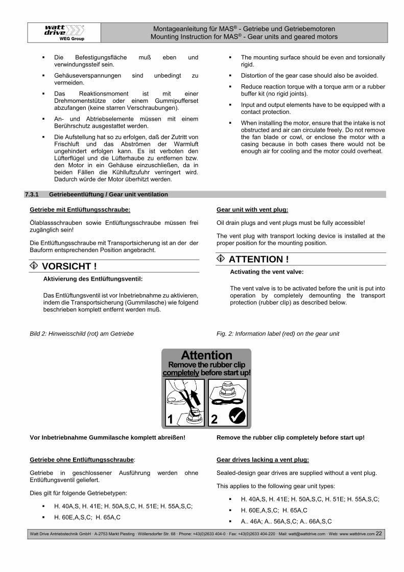
VORSICHT ! Aktivierung des Entlüftungsventil:
Das Entlüftungsventil ist vor Inbetriebnahme zu aktivieren, indem die Transportsicherung (Gummilasche) wie folgend beschrieben komplett entfernt werden muß.
Gear unit with vent plug:
Oil drain plugs and vent plugs must be fully accessible!
The vent plug with transport locking device is installed at the proper position for the mounting position.
ATTENTION ! Activating the vent valve:
The vent valve is to be activated before the unit is put into operation by completely demounting the transport protection (rubber clip) as described below.
Bild 2: Hinweisschild (rot) am Getriebe Fig. 2: Information label (red) on the gear unit
Vor Inbetriebnahme Gummilasche komplett abreißen! Remove the rubber clip completely before start up!
Getriebe ohne Entlüftungsschraube:
Getriebe in geschlossener Ausführung werden ohne Entlüftungsventil geliefert.
Dies gilt für folgende Getriebetypen:
H. 40A,S, H. 41E; H. 50A,S,C, H. 51E; H. 55A,S,C;
H. 60E,A,S,C; H. 65A,C
Gear drives lacking a vent plug:
Sealed-design gear drives are supplied without a vent plug.
This applies to the following gear unit types:
H. 40A,S, H. 41E; H. 50A,S,C, H. 51E; H. 55A,S,C;
H. 60E,A,S,C; H. 65A,C
A.. 46A; A.. 56A,S,C; A.. 66A,S,C

Montageanleitung für MAS® - Getriebe und Getriebemotoren Mounting Instruction for MAS® - Gear units and geared motors
Watt Drive Antriebstechnik GmbH ·A-2753 Markt Piesting ·Wöllersdorfer Str. 68 ·Phone: +43(0)2633 404-0 · Fax: +43(0)2633 404-220 · Mail: [email protected] · Web: www.wattdrive.com 23
A.. 46A; A.. 56A,S,C; A.. 66A,S,C
K.. 40A; K.. 50A,C; K.. 60A,C
K.. 40A; K.. 50A,C; K.. 60A,C
7.3.2 Ölausgleichsbehälter / Lubricant expansion unit
VORSICHT ! Vor Inbetriebnahme muß der Ölausgleichsbehälter am Motorflansch mittels flexiblem Schlauch angeschlossen werden. Dichtheit ist zu überprüfen!
ATTENTION ! Before starting the gear unit the expansion unit must be connected to the motor flange with the flexible pipe.
Leakage test of the expansion unit!
Bild 3: Motor mit Ölausgleichsbehälter Fig. 3: Motor with lubricant expansion unit
Ölausgleichbehälter Flexibler Schlauch Motorflansch
Lubricant expansion unit Flexible pipe Motor flange
7.3.3 Getriebe, Getriebemotor mit Rücklaufsperre / Gear unit, geared motor with backstop
Die Rücklaufsperre erlaubt den Betrieb in nur eine Drehrichtung. Die freie Drehrichtung ist durch einen Drehrichtungspfeil am Abtrieb des Getriebes bzw. auf der Lüfterhaube des Motors gekennzeichnet.
VORSICHT ! Ein Anlauf des Motors mit voller Leistungsaufnahme, entgegen der Sperrrichtung des Getriebes, führt zur Zerstörung oder Beschädigung der Rücklaufsperre.
Die freie Drehrichutng muß vor der Inbetriebnahme geprüft werden.
Getriebe mit Antriebswelleneinheit (WN) und integrierter Rücklaufsperre:
In der Antriebswelleneinheit WN (8), WN (11) und WN (13) kann optional eine Rücklaufsperre eingebaut werden.
Getriebemotor mit Rücklaufsperre am Motor:
Bei Getrieben mit Rücklaufsperre ist die Drehrichtung des E-Motors und des Netzes mit einem Messgerät zu ermitteln. Drehrichtungspfeil auf dem Gehäuse beachten! Bei Motoren,
The backstop allows the operating in only one rotating direction. The free rotating direction is marked with a rotating direction arrow at the output of the gear or on the ventilation cover of the motor.
ATTENTION ! A start-up of the motor with full power consumption against the locking direction of the gear will lead to destruction or damage of the backstop.
The free rotating direction has to be checked before the start-up.
Gear units with a input shaft unit (WN) and integrated back stop:
A backstop can be implemented optionally in the drive shaft unit WN (8), WN (11) and WN (13).
Geared motor with a backstop at the motor:
Using gears with backstop the rotating direction of the e-motor and the mains is to be detected with a meter. Mind the rotating direction arrow on the housing! On motors, which are winded

Montageanleitung für MAS® - Getriebe und Getriebemotoren Mounting Instruction for MAS® - Gear units and geared motors
Watt Drive Antriebstechnik GmbH ·A-2753 Markt Piesting ·Wöllersdorfer Str. 68 ·Phone: +43(0)2633 404-0 · Fax: +43(0)2633 404-220 · Mail: [email protected] · Web: www.wattdrive.com 24
die 400/690 Volt gewickelt sind, kann die Drehrichtung durch kurzzeitigen Anlauf in Sternschaltung ermittelt werden.
400/690 Volt, the rotating direction can be detected through a short-time start-up in star connection.
7.3.4 Getriebe mit Vollwelle / Gear unit with solid shaft
Die Abtriebswellen sind bis zu einem Durchmesser von 50mm nach Toleranzfeld ISO k6 und ab 55mm nach Toleranzfeld ISO m6 gefertigt.
Alle Abtriebswellen sind mit Zentriergewinden nach DIN 332 versehen, die zum Aufziehen von Übertragungselementen benutzt werden sollten.
Alle Abtriebswellen sind bei Lieferung mit einem Konservierungsmittel versehen, der mit einem üblichen Lösungsmittel zu entfernen ist.
VORSICHT ! Das Lösungsmittel darf nicht an die Dichtlippen der
Wellendichtringe kommen!
Schläge und Stöße auf das Wellenende unbedingt vermeiden, da die Abtriebslagerung dadurch beschädigt werden kann.
Mech. Antriebselemente die Radialkräfte auf die Abtriebswelle ausüben sind möglichst nah dem Abtriebslagern zu montieren!
Aufgesetzte Übertragungselemente sollten gewuchtet sein und dürfen keine unzulässigen Radial- oder Axialkräfte hervorrufen (zulässige Werte siehe Katalog).
The output shafts are manufactured with a diameter of 50 mm in ISO k6 tolerance class and beginning at a diameter 55 mm in ISO m6 tolerance class.
All output shafts are equipped with DIN 332 tapped center holes that are used to tighten the transfer elements.
All output shafts are provided with a corrosion protection product upon delivery. This product must be removed with a conventional solvent.
ATTENTION ! The solvent must not be allowed to come into contact
with the shaft seals!
Make certain to prevent all impacts and mechanical shocks on the end of the shaft since the output bearing system can be damaged.
Mechaincal drive elements that apply radial forces to the output shaft must be installed as close as possible to the output shaft bearings!
Add-on power transfer elements should balance and must not cause any unacceptable radial or axial forces (see Catalogue for acceptable values).
7.3.5 Montage und Demontage von Getrieben mit Hohlwelle / Installation and demounting of hollow-shaft gear units
VORSICHT ! Bitte beachten Sie bezüglich der Gestaltung der Kundenwelle die Konstruktionshinweise im aktuellen Getriebemotorenkatalog.
Montage: (siehe Bild 4 bis 6, Seite 25)
Die Montage von Hohlwellengetrieben hat grundsätzlich so zu erfolgen, dass keine axialen Kräfte auf die Abtriebswellenlagerung entstehen.
Überprüfen Sie die Maschinewelle (3) auf eventuelle Schäden wie z.B. Kerben oder Aufstauchungen.
Reinigen Sie vor der Montage die kundenseitige Maschinenwelle (3) sorgfältig.
Vor dem Aufziehen des Hohlwellengetriebes auf die Maschinenwelle tragen Sie auf die Oberfläche der Maschinenwelle eine Schmierpaste (3) wie z.B. Klüber-Paste 46MR401 auf.
Ziehen Sie das Getriebe auf die Maschinenwelle auf (4, 5). Bei einer Kundenwelle ohne Anlageschulter wird ein Distanzrohr (7) benötigt
Setzen Sie das optional erhältliche Befestigungsset in die Hohlwelle ein und sichern Sie die Kundenwelle
ATTENTION ! Concerning the design of the customer’s shaft please mind the construction references in the latest geared motor catalogue.
Assembling: (see Fig. 4 up to Fig. 6 on page 25)
The hollow-shaft gear units must always be installed in such a way that no axial forces are applied to the output shaft bearing system.
Check the machine shaft (3) on possible damages like e.g. notches or upsettings.
Clean the customer’s machine shaft (3) thoroughly before the mounting.
Before tightening the hollow-shaft gear unit onto the machine shaft, paint the surface of the machine shaft with lubricating paste (3) such as Klüber Paste 46MR401.
Mount the drive onto the machine shaft (4, 5). A distance tube (7) is required for a customer’s shaft without contact shoulder.
Implement the optional obtainable fixing set into the hollow shaft and secure the customer’s shaft axial with the locking bolt (4). Screw tightening torque see page 59.

Montageanleitung für MAS® - Getriebe und Getriebemotoren Mounting Instruction for MAS® - Gear units and geared motors
Watt Drive Antriebstechnik GmbH ·A-2753 Markt Piesting ·Wöllersdorfer Str. 68 ·Phone: +43(0)2633 404-0 · Fax: +43(0)2633 404-220 · Mail: [email protected] · Web: www.wattdrive.com 25
mittels der Befestigungsschraube (4) axial. Schrauben-Anzugsmoment siehe Seite 59.
Bild 4:Aufziehen der Kundenwelle ohne oder mit Anlageschulter
Fig. 4: Tightening the customer shaft with or without contact shoulder
Bild 5: Kundenwelle-Befestigung mittels Befestigungsset ohne Anlageschulter
Fig. 5: Mounting the customer shaft using a mounting set without a contact shoulder
Bild 6: Kundenwelle-Befestigung mittels Befestigungsset mit Anlageschulter
Fig. 6: Mounting the customer shaft using a mounting set with a contact shoulder
Gewindestange + Sechskantmutter Druckscheibe Kundenseitige Maschinenwelle Befestigungsschraube DIN6912 Spannscheibe Sicherungsring DIN472 Distanzrohr (nicht im Lieferumfang)
Teil (4), (5) und (6) sind sind im optional erhältlichen Befestigungsset GMBSBSD… enthalten.
Threaded rod + hex nut Thrust washer Customer-side machine shaft Retaining screw DIN6912 Tension disc Circlip DIN472 Space tube (not included in items supplied)
Parts (4), (5) and (6) are included in the optional fixing kit GMBSBSD… .
Demontage:
Lösen Sie die Befestigungschraube (4). Entfernen Sie das komplette Befestigungsset und falls vorhanden das Distanzrohr (7).
Geben Sie die Druckscheibe (11), Abdrückmutter (10) und Sicherungsring (6) in die Hohlwelle.
Schrauben Sie die Befestigungsschraube (9) ein. Durch Anziehen der Schraube dücken Sie das Getriebe von der Maschinenwelle (3) ab.
Demounting:
Loosen the fixing bolt (4). Remove the complete fixing set and, if existing, the distance tube (7).
Put the pressure disc (11), jack nut (10) and circlip (6) into the hollow shaft.
Screw in the fixing bolt (9). Through tightening of the screw you are pressing the gear off the machine shaft (3).
Bild 7: Demontage der Kundenwelle mit oder ohne Anlageschulter
Fig. 7: Demounting the customer shaft with or without contact shoulder
(3) Kundenwelle mit Zentriergewinde nach DIN332, Bl.2 Form DR (6) Sicherungsring DIN 472
(3) Customer's shaft with tapped centre hole as per DIN332, sh.1 (6) Circlip DIN 472

Montageanleitung für MAS® - Getriebe und Getriebemotoren Mounting Instruction for MAS® - Gear units and geared motors
Watt Drive Antriebstechnik GmbH ·A-2753 Markt Piesting ·Wöllersdorfer Str. 68 ·Phone: +43(0)2633 404-0 · Fax: +43(0)2633 404-220 · Mail: [email protected] · Web: www.wattdrive.com 26
(8) Hohlwelle (9) Befestigungsschraube (kundenbezogen, Länge der Schraube entsprechend der Maschinenwellenlänge) (10) Abdrückmutter (11) Druckscheibe
(8) Hollow shaft (9) Retaining screw DIN 933 (to customer specification, length according to machine shaft length) (10) Jack nut (11) Thrust washer
7.3.6 Montage und Demontage von Schrumpfscheiben / Installation and demounting of shrink disks
VORSICHT ! Die Schrumpfscheiben werden einbaufertig geliefert. Diese dürfen nicht vor dem erstmaligen Einbau zerlegt werden. Das Anziehen der Spannschrauben ohne eingebaute Kundenwelle kann zu Verformung der Hohlwelle führen.
Montage (siehe Bild 8, Seite 27):
Entfernen Sie die eventuell vorhandene Abdeckkappe.
Lösen Sie die Spannschrauben (3) um einige Gewindegänge. Nicht ganze herausdrehen!
Entfetten Sie sorgfältig die komplette Hohlwellenbohrung (2, graue Fläche). Diese muß ABSOLUT fettfrei sein!
Entfetten Sie sorgfältig die Maschinenwelle (1, graue Fläche) im Klemmbereich der Schrumpfscheibe. Diese muß ABSOLUT fettfrei sein!
Schieben Sie die Schrumpfscheibe auf die Hohlwelle (2) bis der Aussenring der Schrumpfscheibe mit der Hohlwelle (2) bündig abschließt. Im Bereich des Schrumpfscheiben-Sitzes kann die Außenfläche der Hohlwelle (2) gefettet werden.
Führen Sie die entfettete Maschinenwelle (1) in die Hohlwelle (2) ein, so dass der Bereich der Schrumpfverbindung vollständig ausgenutzt wird.
Ziehen Sie die Spannschrauben (3) der Reihe nach im Uhrzeigersinn über mehrere Umläufe leicht an, damit die beiden Aussenringe (5) parallel zueinander gespannt werden. Die Spannschraubenanzahl hängt von der Schrumpfscheibenbaugröße ab.
VORSICHT ! Spannschrauben (3) nicht „ÜBER KREUZ“ anziehen.
Ziehen Sie die Spannschrauben (3) mit einem Drehmomentschlüssel bis zu dem auf der Schrumpfscheibe angegebenen Anzugsdrehmoment (6) an. Nach dem Festziehen der Spannschrauben (3) muss zwischen den Aussenringen (5) ein gleichmäßiger Spalt vorhanden sein. Falls dies nicht gegeben ist, muss die Schrumpfscheibe nochmals neu montiert werden.
VORSICHT ! Nach erfolgter Montage ist die Hohlwelle bzw. die Maschinenwelle stirnseitig mit einem Strich (Stift) zu kennzeichnen, um ein Durchrutschen während der Inbetriebnahme (unter Last) zu erkennen.
ATTENTION ! The shrink discs are supplied ready to install. They must not be taken apart prior to the first installation. The tightening of the locking bolts without an implemented customer’s shaft can lead to a deformation of the hollow shaft.
Assembling (see Fig. 8, page 27):
Remove the possibly existing cover cap.
Loosen the locking bolts (3) with just a few threads. Do not screw them out completely!
Thoroughly degrease the entire hollow shaft boring (2, grey area). It must be ABSOLUTELY free of grease!
Thoroughly degrease the machine shaft (1, grey area) in the clamping area of the shrink disc. It must be ABSOLUTELY free of grease!
Push the shrink disc onto the hollow shaft (2) until the outer ring of the shrink disc is flush with the hollow shaft (2). The outer part of the hollow shaft (2) can be greased in the area where the shrink disc is fitted.
Insert the degreased machine shaft (1) into the hollow shaft (2) so that the area of the shrink connection is fully used.
Slightly tighten the locking bolts (3) in sequence clockwise with several turns, so that both outer rings (5) are clamped parallel towards each other. The number of locking bolts depends on the size of the shrink disc.
ATTENTION ! Do not tighten the locking bolts (3) „CROSSED“.
Tighten the locking bolts (3) with a torque key up to the
indicated screwing torque (6) on the shrink disc. After the tightening of the locking bolts (3) there has to be an even gap between the outer rings (5). If it is not the case the shrink disc has to be mounted anew.
ATTENTION ! After installation you can sign the hollow shaft respectively the machine shaft with a marking (use a pencil) to detect a slipping during the initial operation (under load).

Montageanleitung für MAS® - Getriebe und Getriebemotoren Mounting Instruction for MAS® - Gear units and geared motors
Watt Drive Antriebstechnik GmbH ·A-2753 Markt Piesting ·Wöllersdorfer Str. 68 ·Phone: +43(0)2633 404-0 · Fax: +43(0)2633 404-220 · Mail: [email protected] · Web: www.wattdrive.com 27
Bild 8: Hohlwelle mit Schrumpfscheibe Fig. 8: Hollow shaft with shrink disc
(1) Kundenseitige Maschinenwelle (2) Hohlwelle (3) Spannschraube (4) Innenring (5) Außenring (6) Anzugsdrehmoment der Spannschrauben (7) Abdrückgewinde
(1) Customer-side machine shaft (2) Hollow shaft (3) Locking screw (4) Inner ring (5) Outer ring (6) Tightening torque of the locking screws (7) Jack nut
Demontage:
Lösen Sie die Spannschrauben (3), gleichmäßig und der Reihe nach. Jede Spannschraube darf anfangs pro Umlauf nur etwa eine Viertel-Umdrehung gelöst werden. Die Spannschrauben nie ganz herausdrehen.
Drücken Sie mit Hilfe des Abdrückgewindes (7) den Innenring (4) ab. Rostansatz, der sich auf der Maschinenwelle vor der Hohlwelle gebildet haben könnte, muß zuvor entfernt werden.
Ziehen Sie die Schrumpfscheibe von der Hohlwelle (2) ab.
Schritt 2 ist nur bei der zweiteiliger Schrumpfscheiben-ausführung möglich !
Demounting:
Undo the locking screws (3) uniformly and in sequence. Only undo each locking bolt about a quarter turn initially. Do not remove the locking bolts completely.
Press the inner ring (4) off using the jack nut (7). Remove any rust beforehand that may have formed on the machine shaft in front of the hollow shaft.
Remove the shrink disc from the hollow shaft (2)
Step 2 only required for two-part shrink disk execution!
7.3.7 Montage von Abdeckkappe / Installation and demounting of protection cap
Abdeckkappen sind vor der Montage auf Transportschäden zu untersuchen. Beschädigte Abdeckkappen dürfen nicht verbaut werden, da sie möglicherweise schleifen können.
Alle Befestigungsschrauben sind zu verwenden und durch Benetzung mit Sicherungsklebstoff (mittelfest), zu sichern. Schrauben-Anzugsmoment siehe Seite 59.
Before being installed, the protection caps must be inspected for any damage that might have occurred during transport. Damaged protection caps must not be installed, since they can possibly cause abrasion.
All of the fixing bolts are to be used and secured by wetting them with a thread-locking adhesive (medium strength). See on page 59 for the bolt tightening torque.
Bild 9: Getriebe mit Hohlwellen-Abdeckkappe
Fig. 9: Protection cap for hollow shaft
Bild 10: Getriebe mit Schrumpfscheiben-Abdeckkappe
Fig. 10: Protection cap for shrink disc hollow shaft
(1) O-Ring bei den Getriebetypen K.. 40. – K.. 110. S.. 454. – S.. 609.
(1) O-ring at gear unit types K.. 40. – K.. 110. S.. 454. – S.. 609.

Montageanleitung für MAS® - Getriebe und Getriebemotoren Mounting Instruction for MAS® - Gear units and geared motors
Watt Drive Antriebstechnik GmbH ·A-2753 Markt Piesting ·Wöllersdorfer Str. 68 ·Phone: +43(0)2633 404-0 · Fax: +43(0)2633 404-220 · Mail: [email protected] · Web: www.wattdrive.com 28
7.3.8 Montage von Normmotoren B5 (IEC 60072, DIN EN 50347) an den IEC-Adapter / Installation of standard motors B5 (IEC 60072, DIN EN 50347) on the IEC adapters
ATEX ! Es dürfen nur IEC - Motoren aufgebaut werden, die eine für die ATEX Zone ausreichende Kategorie gemäß Motortypenschild aufweisen. Bei Getrieben der ATEX - Kategorie 2D muss der Motor mindestens die Schutzart IP6x haben.
Wir liefern IEC Adapter der Baugrößen 100/112 und 132 auch mit einer integrierten spielfreien Klauenkupplung (IAK) aus (siehe Bild 12, Seite 29). Die IEC – Adapter sind öldicht ausgeführt, die Abdichtung der Schnittstelle erfolgt zwischen Getriebe und Adapter.
Montageablauf eines IEC-Normmotors (B5) an den IEC-Adapter IA63 bis IA132:
Reinigen Sie die Motorwelle und die Flanschflächen von Motor und Adapter und überprüfen Sie diese auf Beschädigungen.
Benetzen Sie die Motorwelle vor der Montage mit Schmierpaste wie z.B. Klüberpaste 46 MR 401.
Benetzen Sie die Befestigungsschrauben (1) mit Sicherungsklebstoff (mittelfest).
Setzen Sie danach den Motor auf den Adapter und ziehen Sie die Schrauben (1) (nicht im Lieferumfang) mit dem entsprechenden Moment an. Schrauben mit einer Mindestfestigkeit 8.8 verwenden. Schrauben-Anzugsmoment siehe Seite 59.
ATEX ! Only IEC motors that have a sufficient rating for the ATEX zone per the motor nameplate may be installed. With ATEX category 2D gear units, the motor must be at least protection type IP6x.
We supply also IEC adapters in sizes 100/112 and 132 with an integrated, play-free claw coupling (IAK, see Fig. 12, page 29). The IEC adapters have an oil-tight design, with the interface being sealed between the gears and the adapter.
Assembly procedure for IEC standard motor (B5) on the IEC Adapter IA63 up to IA132:
Clean the motor shaft and the flange surfaces of the motor and adapter and check for damage.
Before installing, wet the motor shaft with lubrication paste, such as Klüber Paste 46 MR 401.
Wet the retaining screws (1) with thread-locking adhesive (medium strength).
Then place the motor on the adapter and tighten the bolts (1) (not included) to the specified torque.Use bolts with minimum property class 8.8. See on page 59 for the bolt tightening torque.
Bild 11: Prinzipdarstellung Montage Normmotor an IEC-Adapter
Fig. 11: Exposition for assembling standard motors on an IEC adapter
Befestigungsschraube Retaining screw

Montageanleitung für MAS® - Getriebe und Getriebemotoren Mounting Instruction for MAS® - Gear units and geared motors
Watt Drive Antriebstechnik GmbH ·A-2753 Markt Piesting ·Wöllersdorfer Str. 68 ·Phone: +43(0)2633 404-0 · Fax: +43(0)2633 404-220 · Mail: [email protected] · Web: www.wattdrive.com 29
Montageablauf eines IEC - Normmotors (B5) an den IEC – Adapter mit Klauenkupplung IAK100, IAK112, IAK132, IAK160, IAK180, IAK200 und IAK225:
Bei der Montage der mitgelieferten Kupplungshälfte auf die Motorwelle ist auf die richtige Einbaulage zu achten. Die Kupplungshälfte ist dabei bündig auf die Motorwelle zu montieren (siehe Bild 12 auf der Seite 29).
Entfernen Sie die Abdeckung des Adapters (1) und entnehmen Sie die beiliegende Kupplungshälfte (3).
Reinigen Sie die Motorwelle (2) und die Flanschflächen von Motor und Adapter.
Erwärmen sie die Kupplungshälfte (3) auf ca. 80°C (176°F) und montieren Sie diese auf die Motorwelle.
Montieren Sie die Kupplungshälfte dabei bündig Wellenspiegel mit Ende der Bohrung (siehe Bild!).
Sichern Sie die Passfeder (4) und die montierte Kupplungshälfte mittels Gewindestift (5) mit dem angegebenen Anzugsdrehmoment TA (M5 ca. 2,5Nm, M8 ca. 10Nm). Verwenden Sie dazu Schraubensicherungsmittel „mittelfest“.
Kontrollieren Sie den korrekten Sitz der Kupplungshälfte.
Die Kontaktfläche zwischen Motor und Adapter ist mit geeignetem Dichtmittel (anaerobe Flächendichtung wie z.B. Loctite 510 oder Silikon wie z.B. Terostat 9140 abzudichten. Dies gilt nur bei Anbau von Motoren nach ATEX.
Montieren Sie den Motor an den Adapter, die Kupplungsklauen müssen beidseitig in den Kupplungsstern (6) eingreifen.
Befestigen Sie den Motor mit den geeigneten Befestigungsschrauben (nicht im Lieferumfang) am Adapter. Schrauben-Anzugsmoment siehe Seite 59. Festigkeitsklasse mindestens 8.8.
Assembly procedure for IEC standard motor (B5) on the IEC adapter with claw coupling IAK100, IAK112, IAK132, IAK160, IAK180, IAK200 and IAK225:
The correct assembly position must be observed when fitting the half coupling supplied onto the motor shaft. The half coupling should be fitted flush to the motor shaft (see figure 12 on page 29).
Remove the adapter cover (1) and remove the half coupling provided (3).
Clean the motor shaft (2) and the flange surfaces on the motor and adapter.
Heat the half coupling (3) to approx. 80°C (176°F) and fit onto the motor shaft.
The half coupling is fitted flush to the shaft panel with the end of the bore hole (see diagram!).
Secure the key (4) and the fitted half coupling using a set pin (5) using the specified tightening torque TA (M5 approx. 2.5Nm, M8 approx. 10Nm). Use a "medium-tight" screw locking adhesive for this purpose.
Check that the half coupling is seated correctly.
The contact surface between the motor and adapter must be sealed with anaerobic sealant e. g. Loctite 510 or silicone e. g. Terostat 9140. This assembling step is only valid for ATEX applications.
Fit the motor onto the adapter; the coupling claws must engage with the coupling star (6) on both sides.
Fasten the motor onto the adapter using the appropriate fastening screws (observe screw tightening torques on page 59, minimum strength class 8.8).
Bild 12: Montage eines IEC – Motors an einen Kupplungsadapter (IAK)
Fig. 12: Installing an IEC motor on the coupling adapter (IAK)
Adapter Motorwelle Kupplungshälfte Passfeder Gewindestift Kupplungsstern Ritzel Wellendichtring Lager
Adapter Motor shaft Half coupling Key Set pin Coupling star Pinion Seal ring Bearing
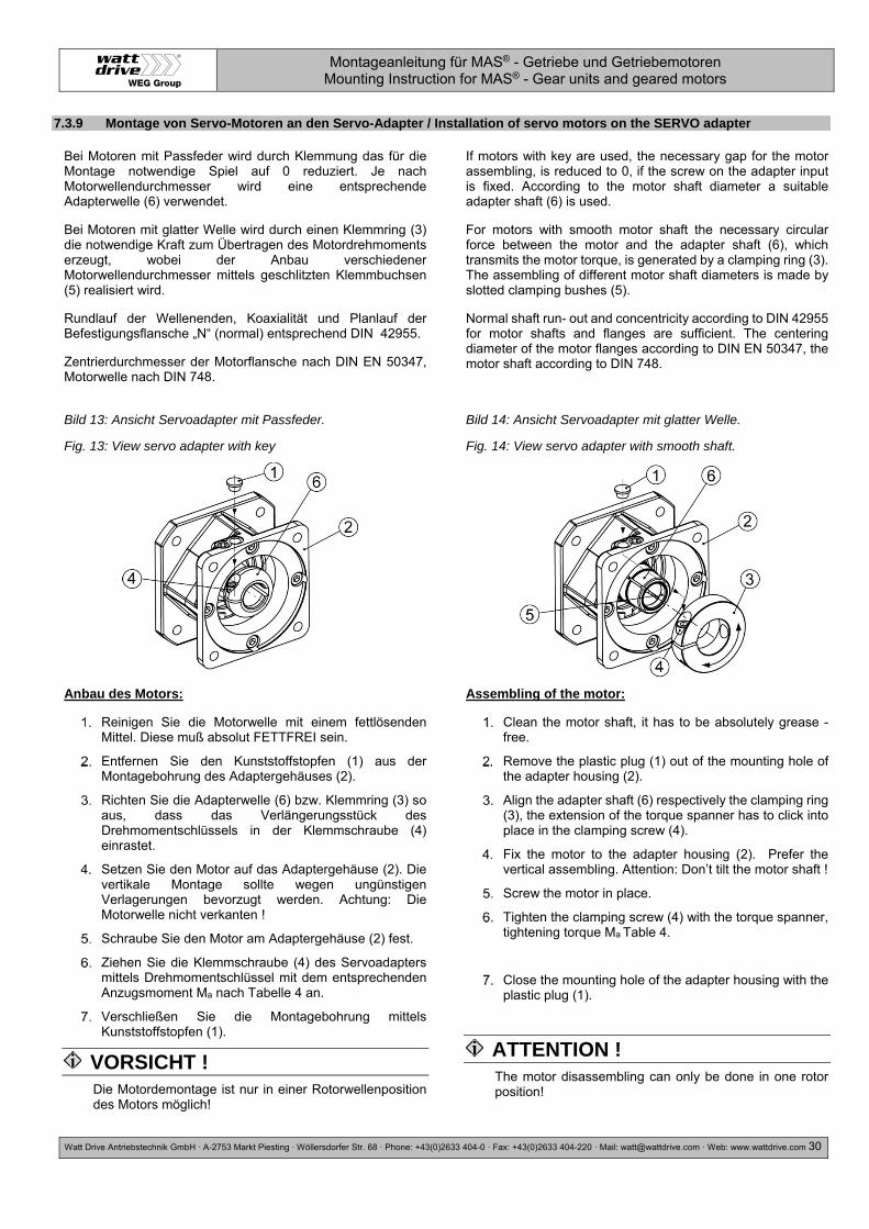
Montageanleitung für MAS® - Getriebe und Getriebemotoren Mounting Instruction for MAS® - Gear units and geared motors
Watt Drive Antriebstechnik GmbH ·A-2753 Markt Piesting ·Wöllersdorfer Str. 68 ·Phone: +43(0)2633 404-0 · Fax: +43(0)2633 404-220 · Mail: [email protected] · Web: www.wattdrive.com 30
7.3.9 Montage von Servo-Motoren an den Servo-Adapter / Installation of servo motors on the SERVO adapter
Bei Motoren mit Passfeder wird durch Klemmung das für die Montage notwendige Spiel auf 0 reduziert. Je nach Motorwellendurchmesser wird eine entsprechende Adapterwelle (6) verwendet.
Bei Motoren mit glatter Welle wird durch einen Klemmring (3) die notwendige Kraft zum Übertragen des Motordrehmoments erzeugt, wobei der Anbau verschiedener Motorwellendurchmesser mittels geschlitzten Klemmbuchsen (5) realisiert wird.
Rundlauf der Wellenenden, Koaxialität und Planlauf der Befestigungsflansche „N“ (normal) entsprechend DIN 42955.
Zentrierdurchmesser der Motorflansche nach DIN EN 50347, Motorwelle nach DIN 748.
If motors with key are used, the necessary gap for the motor assembling, is reduced to 0, if the screw on the adapter input is fixed. According to the motor shaft diameter a suitable adapter shaft (6) is used.
For motors with smooth motor shaft the necessary circular force between the motor and the adapter shaft (6), which transmits the motor torque, is generated by a clamping ring (3). The assembling of different motor shaft diameters is made by slotted clamping bushes (5).
Normal shaft run- out and concentricity according to DIN 42955 for motor shafts and flanges are sufficient. The centering diameter of the motor flanges according to DIN EN 50347, the motor shaft according to DIN 748.
Bild 13: Ansicht Servoadapter mit Passfeder.
Fig. 13: View servo adapter with key
Bild 14: Ansicht Servoadapter mit glatter Welle.
Fig. 14: View servo adapter with smooth shaft.
Anbau des Motors:
Reinigen Sie die Motorwelle mit einem fettlösenden Mittel. Diese muß absolut FETTFREI sein.
Entfernen Sie den Kunststoffstopfen (1) aus der Montagebohrung des Adaptergehäuses (2).
Richten Sie die Adapterwelle (6) bzw. Klemmring (3) so aus, dass das Verlängerungsstück des Drehmomentschlüssels in der Klemmschraube (4) einrastet.
Setzen Sie den Motor auf das Adaptergehäuse (2). Die vertikale Montage sollte wegen ungünstigen Verlagerungen bevorzugt werden. Achtung: Die Motorwelle nicht verkanten !
Schraube Sie den Motor am Adaptergehäuse (2) fest.
Ziehen Sie die Klemmschraube (4) des Servoadapters mittels Drehmomentschlüssel mit dem entsprechenden Anzugsmoment Ma nach Tabelle 4 an.
Verschließen Sie die Montagebohrung mittels Kunststoffstopfen (1).
VORSICHT ! Die Motordemontage ist nur in einer Rotorwellenposition des Motors möglich!
Assembling of the motor:
Clean the motor shaft, it has to be absolutely grease - free.
Remove the plastic plug (1) out of the mounting hole of the adapter housing (2).
Align the adapter shaft (6) respectively the clamping ring (3), the extension of the torque spanner has to click into place in the clamping screw (4).
Fix the motor to the adapter housing (2). Prefer the vertical assembling. Attention: Don’t tilt the motor shaft !
Screw the motor in place.
Tighten the clamping screw (4) with the torque spanner, tightening torque Ma Table 4.
Close the mounting hole of the adapter housing with the plastic plug (1).
ATTENTION ! The motor disassembling can only be done in one rotor position!

Montageanleitung für MAS® - Getriebe und Getriebemotoren Mounting Instruction for MAS® - Gear units and geared motors
Watt Drive Antriebstechnik GmbH ·A-2753 Markt Piesting ·Wöllersdorfer Str. 68 ·Phone: +43(0)2633 404-0 · Fax: +43(0)2633 404-220 · Mail: [email protected] · Web: www.wattdrive.com 31
Tabelle 4: Erforderliche Anzugsmoment Ma der Klemmschraube für Servoadapter mit und ohne Paßfeder:
Table 4: Requried tightening torque Ma for the clamping screw of the servo adapter with key and with smooth shaft:
Klemmschraube Clamping screw
„s“ Ma [Nm]
M6 5 9,5 M8 6 20
M10 8 48 M12 10 94
7.3.10 Montage von Drehmomentstützen / Installation of torque arms
VORSICHT ! Drehrichtung der Hohlwelle beachten!
Die Urelastfedern des Gummipuffersets sind in der Hauptarbeitsdrehrichtung auf Druck zu beanspruchen!
Empfohlene Vorspannung der Urlelastfeder 3mm pro Puffer.
ATTENTION ! Pay attention to the direction of rotation of the hollow shaft!
The Urelast springs in the rubber buffer set are to be loaded under compression in the main working direction of rotation!
Recommended pre loading 3mm per Urelast spring.
Bild 15: Aufsteckgetriebe
Fig. 15: Shaft mounted gear unit
Bild 16: Stirnradschneckengetriebe
Fig. 16: Helical worm gear unit
R L
R … Rechtslauf / Clockwise
L … Linkslauf / Counterclockwise

Montageanleitung für MAS® - Getriebe und Getriebemotoren Mounting Instruction for MAS® - Gear units and geared motors
Watt Drive Antriebstechnik GmbH ·A-2753 Markt Piesting ·Wöllersdorfer Str. 68 ·Phone: +43(0)2633 404-0 · Fax: +43(0)2633 404-220 · Mail: [email protected] · Web: www.wattdrive.com 32
Bild 17: Kegelstirnradgetriebe (*) . . . Buchse muß beidseitg gelagert werden. K.. 40. - K.. 77.
Fig. 17: Helical bevel gear unit (*) . . . Bushing must have bearings on both sides. K.. 80. - K.. 139.
R L
(*)

Montageanleitung für MAS® - Getriebe und Getriebemotoren Mounting Instruction for MAS® - Gear units and geared motors
Watt Drive Antriebstechnik GmbH ·A-2753 Markt Piesting ·Wöllersdorfer Str. 68 ·Phone: +43(0)2633 404-0 · Fax: +43(0)2633 404-220 · Mail: [email protected] · Web: www.wattdrive.com 33
8 Checkliste – Getriebe / Check list – Gear unit
Vor Inbetriebnahme des Getriebes ist zu überprüfen:
Informationen siehe Kapitel
Geprüft
Untersuchen Sie die Lieferung sofort nach Erhalt auf etwaige Transportschäden. Die Inbetriebnahme ist ggf. nicht durchzuführen.
Entspricht die Bauform auf dem Typenschild der tatsächlichen Einbaulage? 3.1, 15
Ist das Entlüftungsventil an der richtigen Stelle (der Bauform entsprechend) montiert und frei zugänglich?
15
Ist das Entlüftungsventil aktiviert (Gummilasche entfernt)? 7.3.1
Wurde bei einer Schrumpfscheibenausführung die Verbindung geprüft? 7.3.6
Wurde die freie Drehrichtung bei Verwendung einer Rücklaufsperre überprüft? 7.3.3
Ist bei drehenden Teilen der Berührschutz angebracht?
Stimmen die folgenden Angaben auf dem Typenschild des Getriebes mit dem zulässigen Ex-Einsatzbereich vor Ort überein? – Gerätegruppe, - Ex-Kategorie, - Atmosphäre, - Temperaturklasse, - maximale Oberflächentemperatur
3.1
Ist sichergestellt, dass bei der Montage des Getriebes keine explosionsfähige Atmosphäre, Öle, Säuren,Gase, Dämpfe oder Strahlungen vorhanden sind?
7.1
Ist sichergestellt, dass die Getriebe ausreichend belüftet werden und kein externer Wärmeeintrag (z. B. über Kupplungen) vorhanden ist? Die Kühlluft darf eine Temperatur von 40°C nicht überschreiten.
7.1
Haben alle An- und Abtriebselemente eine ATEX - Zulassung? 7.1
Hat der Motor eine entsprechende ATEX- Zulassung? 7.3.8
Check the following before starting up the gear unit:
Informations see chapter
checked
Inspect the shipment immediately after reception for any transport damages. In some cases, it may not be advisable to start up the unit.
Does the mounting position on the nameplate correspond to the actual mounting position ? 3.1, 15
Is the vent plug located at the correct location (in compliance with the installation position) and freely accessible?
15
Is the vent plug activated (rubber flap removed)? 7.3.1
In the case of a shrink disc version: has the expansion been checked? 7.3.6
Has the free rotating direction been checked when using a backstop? 7.3.3
Is protection provided around rotating parts to prevent personnel from coming into contact with them?
Do the data on the nameplate of the drive unit agree with the local explosion usage area on the drive unit nameplate? - Instrument group, - Ex-category, - Atmosphere, - Temperature class, -Maximum surface tension
3.1
Has it been ascertained that no atmosphere is capable of exploding, oils, acid, gases, vapors, or radiation are present when the gear unit is being installed?
7.1
Has it been ascertained that the gear unit is adequately ventilated and that no outside source of heat can be transferred into the unit (for example via clutches)? The cooling air must not exceed a temperature of 40°C.
7.1
Do all input and output elements have an ATEX approval? 7.1
Does the motor have a corresponding ATEX approval? 7.3.8

Montageanleitung für MAS® - Getriebe und Getriebemotoren Mounting Instruction for MAS® - Gear units and geared motors
Watt Drive Antriebstechnik GmbH ·A-2753 Markt Piesting ·Wöllersdorfer Str. 68 ·Phone: +43(0)2633 404-0 · Fax: +43(0)2633 404-220 · Mail: [email protected] · Web: www.wattdrive.com 34
9 Checkliste – Motor / Check list – Motor
Vor Inbetriebnahme des Motors ist zu überprüfen: Informationen
siehe Kapitel Geprüft
Stimmt die Netzspannung und Frequenz mit den angeführten Daten am Motorleistungsschild überein? Wurden alle Anschlüsse ordnungsgemäß ausgeführt (Motoranschluss, Erdungsleiter,…)? Ist der Motoranschluss ident mit dem beiliegendem Schaltbild?
7.2.3
Stimmt die Drehrichtung des Motors/Getriebemotors? 10.2 Wurde die freie Drehrichtung bei Verwendung einer Rücklaufsperre überprüft? 7.3.3 Anschlusskasten staub- und wasserdicht verschlossen? 7.2.1 Motorschutzschalter installiert? 10.1 Sind alle Motorschutzeinrichtungen aktiv und auf den Bemessungsstrom des Motors eingestellt ? Isolationswiderstand überprüft? 7.2.2 Optionale Stillstandsheizung ausgeschalten? 17.1 Optionale Fremdlüftung an eine externe Stromversorgung angeschlossen? 17.3
Check the following before starting up the motor:
Informations see chapter
checked
Check that the mains voltage and frequency correspond to the data on the motor rating plate? All connections have been made properly (motor connection, ground conductor,…)? 7.2.3 Is the direction of rotation of the motor/geared motor correct? 10.2 Has the free rotating direction been checked when using a backstop? 7.3.3 Is the terminal box dust and watertight? 7.2.1 Is a motor circuit breaker installed? 10.1 Is all motor protection equipment active and set for the rated motor current? Has the insulation resistance been checked? 7.2.2 Optional anti-condensation heating is switched off? 17.1 Optional forced cooling is connected to an external power supply? 17.3

Montageanleitung für MAS® - Getriebe und Getriebemotoren Mounting Instruction for MAS® - Gear units and geared motors
Watt Drive Antriebstechnik GmbH ·A-2753 Markt Piesting ·Wöllersdorfer Str. 68 ·Phone: +43(0)2633 404-0 · Fax: +43(0)2633 404-220 · Mail: [email protected] · Web: www.wattdrive.com 35
10 Inbetriebnahme / Startup
Elektrischer Anschluss des Motor / Electrical connecting the motor
Netzspannung und -frequenz müssen mit den Daten auf dem Tpyenschild übereinstimmen. Spannungsabweichungen von ± 5% und/oder Frequenzabweichungen von ± 2% sind zulässig.
VORSICHT ! Der Anschluss des Motors erfolgt nach dem Anschluss-Schaltbild, welche dem Motor im Anschlusskasten beigefügt sind.
Das Schaltbild der Motorserie 3A, 3B und 3C finden Sie auch in dieser Betriebsanleitung auf der Seite 52. Es muss eine dauerhaft sichere, elektrische Verbindung aufrecht erhalten werden (keine abstehenden Drahtenden); zugeordnete Kabelendbestückung verwenden.
VORSICHT ! Ein Motorschutzschalter bzw. ein Schutz mit Überstromrelais zum Schutz der Motorwicklungen sollte installiert werden. Schmelzsicherungen schützen den Motor nicht vor Überlastungen sondern lediglich die Netzzuleitungen oder Schaltanlagen gegen Schäden bei Kurzschluss. Vor jedem Einschalten muss sichergestellt sein, dass die optionale Stillstandsheizung ausgeschaltet wird.
The mains voltage and the mains frequency must match the data on the nameplate. Voltage deviations of ± 5% and/or frequency deviations of ± 2% are allowable.
ATTENTION ! Connect the motor only as shown in the wiring diagram included in the terminal box of the motor.
The wiring diagram for the motor series 3A, 3B and 3C is available in this manual on page 52. Connections must be made in such a way as to ensure that a permanently safe electrical connection is maintained (no protruding wire ends); use the corresponding cable end pieces.
ATTENTION ! A motor circuit breaker or contactor with an overcurrent relay should be installed to prevent the motor winding from burning out. Fuses do not stop the motor overloading, but merely protect the power cables or switchgear from damage in the event of a short circuit. Before energizing the motor, always make sure that the optional anti-condensation heating is switched off.
Drehrichtung / Direction of rotation
Standardmäßig sind die Motoren für Rechts- und Linkslauf geeignet. Wenn die Netzleitungen mit der Phasenfolge L1, L2, L3 an U1, V1, W1 angeschlossen werden, ergibt sich Rechtslauf (Blick auf antriebsseitiges Wellenende).
Werden zwei Anschlüsse vertauscht, ergibt sich Linkslauf (z.B. L1, L2, L3 an V1, U1, W1).
The standard motors are suitable for clockwise and counter-clockwise rotation. Connection of the power cables in the phase sequence L1, L2, L3 to U1, V1, W1 results in clockwise rotation (looking at the shaft end on the drive side).
If two connections are interchanged, this results in counterclockwise rotation (e.g. L1, L2, L3 to V1, U1, W1).
Ölstand des gelieferten Getriebes / Oil level in the gear unit as delivered
VORSICHT ! Der bauformgerechte Ölstand wird werksseitig ausgeführt. Genaue Ölfüllmenge siehe Getriebe-Typenschild.
Antriebe, welche ohne Ölfüllung bestellt werden, kommen mit Innenkonservierung zur Auslieferung. Die Innenkonservierung der Getriebe erfolgt mit Korrosionsschutzöl. Das Konservierungsöl ist auf jeden Fall mit der am Typenschild angegebenen Öltype mischbar, sodass die Getriebe vor der Befüllung nicht ausgespült werden müssen.
ATTENTION ! The proper oil level for the mounting position is designed by the plant. See gear unit nameplate for the precise amount of oil to add.
Gear units that are ordered without oil filling are supplied with internal rust proofing consisting of anti-corrosion oil. The anti-corrosion oil can however be mixed with the recommended lubricant indicated on the nameplate. This means that the unit does not have to be flushed before filling with oil.

Montageanleitung für MAS® - Getriebe und Getriebemotoren Mounting Instruction for MAS® - Gear units and geared motors
Watt Drive Antriebstechnik GmbH ·A-2753 Markt Piesting ·Wöllersdorfer Str. 68 ·Phone: +43(0)2633 404-0 · Fax: +43(0)2633 404-220 · Mail: [email protected] · Web: www.wattdrive.com 36
VORSICHT ! Ein Bauformenwechsel darf nur nach vorheriger Rücksprache mit dem Hersteller erfolgen.
Im Fall einer Öffnung des Getriebes z.B.: wegen einer Reparatur, ist es notwendig, dass das Getriebe vor der Inbetriebnahme wieder gemäß den Angaben auf dem Typenschild mit dem richtigen Schmierstoff, in der richtigen Menge befüllt wird. Schmierstoffe siehe Seite 41.
ATTENTION ! A change in the mounted position must not be made before consulting the producer.
If the gear unit is opened, for example: to make repairs, it must be filled with the correct lubricant in the correct amount as stated on the nameplate before being put back into service. For lubricants, see on page 41.
11 Betrieb / Operation
Während des Betriebs unter maximaler Belastung ist das Getriebe zu prüfen auf:
ungewöhnliche Geräusche
Vibrationen und ungewöhnliche Schwingungen
Rauchbildung
Undichtheit
Bei Schrumpfscheibenausführungen: Nach dem Entfernen der Abdeckkappe ist zu prüfen, ob eine Relativbewegung zwischen Hohlwelle und Maschinenwelle stattgefunden hat. Anschließend ist die Abdeckhaube wieder zu montieren.
Maximale Gehäuseoberflächentemperatur 90°C.
Gehäuseoberflächentemperatur:
Die Oberflächentemperatur ist während des Betriebs im maximalen Belastungszustand zu messen. Die max. Oberflächentemperatur ist nach ca. 3 Stunden erreicht und darf 90°C nicht überschreiten.
Die Messung der Oberflächentemperatur ist mit handelsüblichen Temperaturmessgeräten durchzuführen.
VORSICHT ! Der Antrieb muss stillgesetzt werden, wenn bei der Kontrolle der Getriebe Auffälligkeiten hinsichtlich der oben angeführten Punkte festgestellt wurden. Es ist Rücksprache mit dem Hersteller zu halten.
During the operation, the gear unit must be tested under maximum load for:
unusual noises
vibrations and unusual oscillations
smoke formation
Leaks
With shrink disc types: After demounting the cover cap, check whether any relative movement has occurred between the hollow shaft and the machine shaft. Then reinstall the cover guard.
Maximum gear housing temoperature 90°.
Gear housing temperature:
During the operation, the surface temperature must be measured in the maximum operating condition. The max. surface temperature is reached in about 3 hours, and it must not exceed 90°C.
The surface temperature shall be measured with standard commercially available temperature-measuring instruments.
ATTENTION ! The drive must be shut down if any abnormalities relative to the items listed above have been noted upon inspection. Contact the producer.
12 Betriebsstörungen / Malfunction
Bei benötigter Hilfe bitte folgende Angaben bereithalten:
Typenschilddaten
Art der Störung
Zeitpunkt und Begleitumstände der Störung
Mögliche Ursache
VORSICHT ! Unsachgemäße Arbeiten am Getriebe oder Motor können zu Schäden führen. Sollten Störungen am Getriebe bzw. Getriebemotor auftreten, muss der Antrieb sofort stillgesetzt werden !
Please provide the following information if help is needed:
Data from the nameplate
Type of problem
Time the problem occurred and circumstances accompanying the problem
Possible cause
ATTENTION ! Incorrect work on the gear or motor can lead to damages. Should errors emerge at the gear or gearbox, the drive has to be stopped immediately!

Montageanleitung für MAS® - Getriebe und Getriebemotoren Mounting Instruction for MAS® - Gear units and geared motors
Watt Drive Antriebstechnik GmbH ·A-2753 Markt Piesting ·Wöllersdorfer Str. 68 ·Phone: +43(0)2633 404-0 · Fax: +43(0)2633 404-220 · Mail: [email protected] · Web: www.wattdrive.com 37
Mögliche Störungen am Getriebe: Possible malfunctions on the gear unit:
Störung Mögliche Ursache Beseitigung Ungewöhnliche, gleichmäßige Lauf-geräusche.
Lagerschaden, Verzahnungsschaden
Rücksprache mit dem Hersteller.
Ungewöhnliche, ungleichmäßige Lauf-geräusche.
Fremdkörper im Öl. Ölwechsel durchführen.
Bewegungen des Getriebes beim Einschalten.
Getriebebefestigung hat sich gelockert.
Befestigungsschrauben, - muttern mit vorgeschriebenem Drehmoment anziehen. Beschädigte Befestigungsschrauben, - muttern austauschen.
Gummipufferset bei Drehmoment-stütze nicht vorgespannt bzw. beschädigt.
Gummipurfferset korrekt vorspannen bzw. beschädigtes Gummipufferset austauschen.
Getriebe wird zu warm (Getriebeober-flächentemp. > 90°C).
Zu viel Öl. Ölfüllmenge korrigieren. Getriebeschaden (Verzahnung, Lagerung)
Rücksprache mit dem Hersteller.
Entlüftungsventil defekt. Entlüftungsventil austauschen.
Ölaustritt am Getriebe oder Motor. Dichtung defekt. Dichtungen kontrollieren, ggf. auswechseln.
Getriebe nicht entlüftet. Transportsicherung am Entlüftungsventil entfernen.
Ölaustritt am Entlüftungsventil.
Zu viel Öl. Ölfüllmenge korrigieren.
Getriebe wird in falscher Bauform betrieben.
Entlüftungsventil an die korrekte Position montieren. Ölfüllmenge der Bauform entsprechend anpassen.
Entlüftungsventil defekt. Entlüftungsventil austauschen.
Getriebeabtriebswelle dreht sich nicht obwohl Motor läuft bzw. Antriebswelle gedreht wird.
Bruch im Getriebe oder Wellen-Narbenverbindung unterbrochen.
Rücksprache mit dem Hersteller.
Schrumpfscheibenverbindung rutscht durch.
Schrumpfscheibenverbindung kontrollieren.
Malfunction Possible Cause Settling Unusual, even operating noise. Bearing damage, gearing damage. Consult the producer. Unusual, uneven operating noise. Foreign object in the oil. Perform an oil change. Movement of the gear unit during switch-on.
Gear unit fixation has loosened. Tighten the fixing bolts, - nuts with prescribed screwing torque. Change damaged fixing bolts, - nuts.
Rubber buffer set at the torque support is not pre-stressed or damaged.
Pre-stress the rubber buffer set correctly or change the damaged rubber buffer set.
Gear unit gets too warm (Gear surface temp. > 90°C).
Too much oil. Correct the oil fill capacity. Gear unit damage (gearing, bearing). Consult the producer. Vent plug is defective. Change the vent plug.
Oil leakage at the gear unit or motor. Gasket is damaged. Check gaskets, change them if necessary. Gear unit is not ventilated. Remove the transport lock at the vent plug.
Oil leakage at the vent plug. Too much oil. Correct the oil fill capacity. Gear unit is operated with the wrong type.
Mount the vent plug at the correct position. Adjust the oil fill capacity according to the type.
Vent plug is defect. Change the vent plug. The gear unit output shaft does not turn though the motor runs or the drive shaft is being turned.
Breakage in the gear unit or shaft hub connection disrupted.
Consult the producer.
Shrink disc connection slips through. Check the shrink disc connection.
13 Inspektion und Wartung / Inspection and maintenance
Getriebe der Baureihen H, A, F, K in den Größen 40, 41, 50, 51, 55, 60, 65 werden wartungsfrei ausgeführt, es ist kein Wechsel des Schmiermittels erforderlich. Diese Antriebe werden ohne Entlüftungsventil ausgeführt, es gibt keine Ölablass-, Ölstands- bzw. Ölbefüllschrauben.
Gear units of the model range H, A, F, K, size 40, 41, 50, 51, 55, 60, 65 are maintenance-free, an oil change is not necessary. The gear units are executed without vent plug, there are no oil drain-, oil level respectively oil filling screws.

Montageanleitung für MAS® - Getriebe und Getriebemotoren Mounting Instruction for MAS® - Gear units and geared motors
Watt Drive Antriebstechnik GmbH ·A-2753 Markt Piesting ·Wöllersdorfer Str. 68 ·Phone: +43(0)2633 404-0 · Fax: +43(0)2633 404-220 · Mail: [email protected] · Web: www.wattdrive.com 38
Bei Getrieben der Baureihen H, A, F, K und C in den Größen 70, 75, 80, 86, 110, 111, 130, 131, 133, 136, 137, 139 und bei allen Stirnradschneckengetrieben Baureihe S ist entsprechend den Wartungsintervallen ein Schmierstoffwechsel durchzuführen. Diese Getriebe sind für die Hauptbauformen mit entsprechenden Ölablass- bzw. Ölbefüllschrauben ausgestattet.
Bei Sonderausführungen unter erschwerten/aggresiven Umgebungsbedingungen Öl öfters wechseln!
In the case of gear units of model range H, A, F, K and C size 70, 75, 80, 86, 110, 111, 130, 131, 133, 136, 137, 139 and all helical worm gear units, an oil change has to be executed corresponding to the maintenance periods. The gear units are executed with oil drain-, respectively oil filling screws for the main mounting positions.
For special applications under difficult/aggressive ambient conditions an oil change has to be done frequently!
Inspektions- und Wartungsintervalle / Inspection and maintenance intervals
Zeitintervall Inspektions- und Wartungsarbeit
monatlich
Getriebe auf Geräuschveränderungen (Laufgeräusche der Verzahnung und der Wälzlager) kontrollieren
Gehäusetemperatur kontrollieren (max. 90°C, 194°F) Sichtkontrolle der Dichtungen auf Leckage (Ölaustritt) Sichkontrolle Ölschauglas im Rührwerksflansch Staubablagerungen entfernen
alle 3 Monate Entlüftungsventil äußerlich reinigen
halbjährlich Gummipuffer überprüfen Befestigungsschrauben auf festen Sitz kontrollieren
jährlich Lagerung in Rührwerksflansch nachfetten
Alle 5.000 Betriebsstunden, spätestens alle 4 Jahre
Sichtprüfung der Wellendichtringe auf Leckage; gegebenenfalls Wellendichtringe tauschen
alle 10.000 Betriebsstunden, spätestens alle 5 Jahre
Ölwechsel: Stirnradgetriebe H. 70. - H. 136. Flachgetriebe F.. 111. - F.. 137. Aufsteckgetriebe A.. 76. - A.. 86. Kegelstirnradgetriebe K.. 70. - K.. 139. Kegelflachgetriebe C.. 70. - C.. 130.
alle 20.000 Betriebsstunden, spätestens alle 5 Jahre
Ölwechsel: alle Stirnradschneckengetriebe
alle 10 Jahre Generalüberholung regelmässig nach Bedarf
(abhängig von äußeren Einflüssen) Bremsluftspalt überprüfen Lüfterrad des Motors reinigen
Time interval Inspection and maintenance work
monthly
gear units must be checked for noise changes (running noise of the gearing and rolling bearings)
Check the housing temperature (max. 90°C, 194°F) Visible inspection of seals for leakage (Oil leakage) Visible inspection of oil level gauge in the agitator flange Remove dust deposits
every 3 months Clean the exterior of the vent plug
every half year Check the rubber buffer set Check the fixing bolts to make certain they are tight
annually Grease the bearing in the agitator flange
every 5.000 service hours, no later than every 4 years
Visual check of the shaft seals; if applicable replace the shaft seals
every 10.000 service hours, no later than every 5 years
Oil change: Helical gear unit H. 70. - H. 136. Parallel shaft gear unit F.. 111. - F.. 137. Shaft mounted gear unit A.. 76. - A.. 86. Helical bevel gear unit K.. 70. - K.. 139. Angle parallel shaft gear unit C.. 70. - C.. 130.
every 20.000 service hours, no later than every 5 years
Oil change: All helical worm gear units
every 10 years General recovery Regularly on demand (depending on
outside influences) Check the air gap Clean the fan wheel of the motor

Montageanleitung für MAS® - Getriebe und Getriebemotoren Mounting Instruction for MAS® - Gear units and geared motors
Watt Drive Antriebstechnik GmbH ·A-2753 Markt Piesting ·Wöllersdorfer Str. 68 ·Phone: +43(0)2633 404-0 · Fax: +43(0)2633 404-220 · Mail: [email protected] · Web: www.wattdrive.com 39
Inspektions- und Wartungsarbeiten Getriebe / Inspection and maintenance work on gear unit
GEFAHR ! Bei allen Wartungs- und Instandhaltungsarbeiten darf keine explosive Atmosphäre vorhanden sein. Wartungs- und Instandhaltungsarbeiten dürfen nur von qualifiziertem Fachpersonal ausgeführt werden.
Wartungs- und Instandhaltungsarbeiten sind nur bei stillstehendem, spannungsfreiem und gegen versehentliches Einschalten abgesichertem Antrieb durchzuführen.
GEFAHR ! Vor Beginn der Arbeiten Getriebe abkühlen lassen. Verbrennungsgefahr !
Sichtkontrolle der Dichtungen auf Leckage:
Es ist auf austretendes Getriebeöl bzw. Ölspuren zu achten, wobei besonders Wellendichtringe und Verschlusskappen sowie Dichtflächen zu kontrollieren sind.
Sichkontrolle Ölschauglas im Rührwerksflansch:
Siehe Bild 18 Seite 40. Sollte Öl sichtbar sein, muß der Wellendichtring im Getriebegehäuse ausgetauscht werden.
Gummipuffer überprüfen:
Die Gummipuffer sind auf sichtbare Schäden wie Risse an der Oberfläche zu überprüfen und gegebenenfalls zu tauschen.
Staubablagerungen entfernen:
Auf dem Getriebe abgelagerte Staubschichten sind zu entfernen, bei Getriebeausführung mit Abdeckkappe, ist diese zu entfernen und ebenfalls zu reinigen. Danach muss die Abdeckkappe wieder montiert werden (siehe Seite 27).
Wellendichtringe wechseln:
Beim Wechsel des Dichtringes ist darauf zu achten, dass je nach Ausführung ein ausreichendes Fettdepot zwischen Staub- und Dichtlippe vorhanden ist.
Beim Einsatz von doppelten Dichtringen ist der Zwischenraum zu einem Drittel mit Fett zu füllen.
Ölwechsel:
Vor Beginn der Arbeiten Getriebe abkühlen lassen ! Öl muß jedoch noch warm sein damit eine vollständige Enleerung leichter durchgefürt werden kann (mangelnde Fließeigenschaft).
Stellen Sie ein passendes Gefäß unter die Ölablass- bzw. Verschlussschraube.
Entfernen Sie die Entlüftungs- und Ölablassschraube.
Lassen Sie das Öl vollständig ab.
Drehen Sie die Ölablass- bzw. Verschlussschraube wieder vollständig ein.
WARNING ! No explosive atmosphere may be prevented in any maintenance or repair work. Maintenance and repair work must only be performed by qualified specialists in the field.
Maintenance and repair work are only to be carried out on a drive, which is in standstill with zero potential and secured against accidental switch on.
WARNING ! Before beginning the work let the gear cool down. Danger of burning!
Visible inspection of seals for leakage:
Make certain that no gear oil is leaking and that no oil traces can be found. In particular, the shaft seals and locking caps, as well as the sealing surface must be checked.
Visual control oil inspection glass in the agitator flange:
See fig. 19 page 40. Should Oil be visible the shaft seal in the gear housing has to be exchanged.
Check the rubber buffer set:
The rubber buffer set must be checked for visible damage, such as cracks on the surface, and they must be replaced in some cases.
Remove dust deposits:
Remove any layers of dust that have accumulated on the gear unit. If the gear unit design included a protection cap, remove it and clean it too. Then reinstall the protection cap (see on page 27).
Change the shaft seals:
When changing the shaft seal, make certain that, depending on the design, a sufficient deposit of grease is present between the dust lip and the sealing lip.
When using double seals, fill one-third of the space between them with grease.
Oil change:
Let the gear cool down before beginning with the work! The oil still has to be warm to make a complete emptying easier (poor flow characteristics).
Put an appropriate container under the air vent- and oil drain plug.
Remove the air vent- and oil drain plug.
Let the oil drain completely.
Turn in the plug completely again.
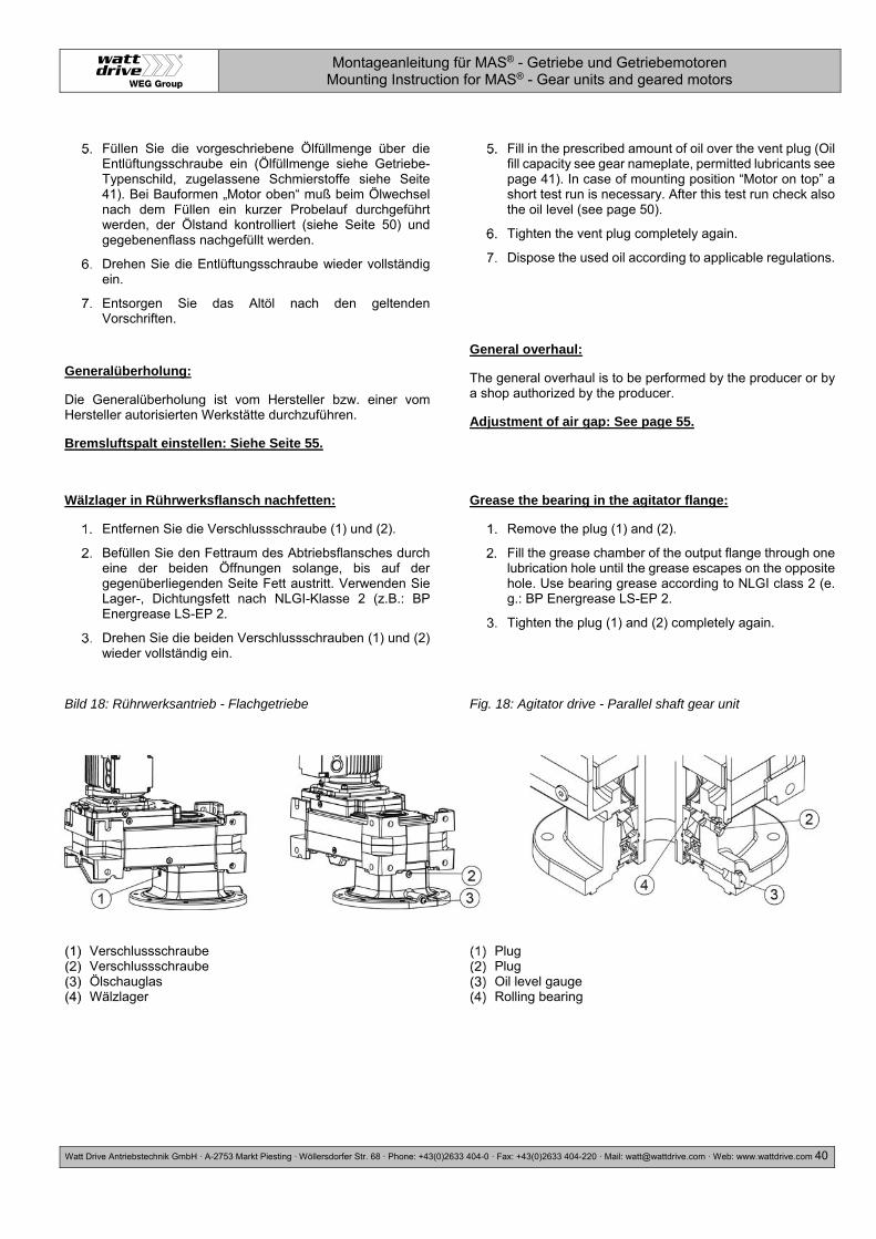
Montageanleitung für MAS® - Getriebe und Getriebemotoren Mounting Instruction for MAS® - Gear units and geared motors
Watt Drive Antriebstechnik GmbH ·A-2753 Markt Piesting ·Wöllersdorfer Str. 68 ·Phone: +43(0)2633 404-0 · Fax: +43(0)2633 404-220 · Mail: [email protected] · Web: www.wattdrive.com 40
Füllen Sie die vorgeschriebene Ölfüllmenge über die Entlüftungsschraube ein (Ölfüllmenge siehe Getriebe-Typenschild, zugelassene Schmierstoffe siehe Seite 41). Bei Bauformen „Motor oben“ muß beim Ölwechsel nach dem Füllen ein kurzer Probelauf durchgeführt werden, der Ölstand kontrolliert (siehe Seite 50) und gegebenenflass nachgefüllt werden.
Drehen Sie die Entlüftungsschraube wieder vollständig ein.
Entsorgen Sie das Altöl nach den geltenden Vorschriften.
Generalüberholung:
Die Generalüberholung ist vom Hersteller bzw. einer vom Hersteller autorisierten Werkstätte durchzuführen.
Bremsluftspalt einstellen: Siehe Seite 55.
Fill in the prescribed amount of oil over the vent plug (Oil fill capacity see gear nameplate, permitted lubricants see page 41). In case of mounting position “Motor on top” a short test run is necessary. After this test run check also the oil level (see page 50).
Tighten the vent plug completely again.
Dispose the used oil according to applicable regulations.
General overhaul:
The general overhaul is to be performed by the producer or by a shop authorized by the producer.
Adjustment of air gap: See page 55.
Wälzlager in Rührwerksflansch nachfetten:
Entfernen Sie die Verschlussschraube (1) und (2).
Befüllen Sie den Fettraum des Abtriebsflansches durch eine der beiden Öffnungen solange, bis auf der gegenüberliegenden Seite Fett austritt. Verwenden Sie Lager-, Dichtungsfett nach NLGI-Klasse 2 (z.B.: BP Energrease LS-EP 2.
Drehen Sie die beiden Verschlussschrauben (1) und (2) wieder vollständig ein.
Grease the bearing in the agitator flange:
Remove the plug (1) and (2).
Fill the grease chamber of the output flange through one lubrication hole until the grease escapes on the opposite hole. Use bearing grease according to NLGI class 2 (e. g.: BP Energrease LS-EP 2.
Tighten the plug (1) and (2) completely again.
Bild 18: Rührwerksantrieb - Flachgetriebe Fig. 18: Agitator drive - Parallel shaft gear unit
Verschlussschraube Verschlussschraube Ölschauglas Wälzlager
Plug Plug Oil level gauge Rolling bearing

Montageanleitung für MAS® - Getriebe und Getriebemotoren Mounting Instruction for MAS® - Gear units and geared motors
Watt Drive Antriebstechnik GmbH ·A-2753 Markt Piesting ·Wöllersdorfer Str. 68 ·Phone: +43(0)2633 404-0 · Fax: +43(0)2633 404-220 · Mail: [email protected] · Web: www.wattdrive.com 41
14 Schmierstoffe / Lubricants
Wird keine Sonderregelung bezüglich des Schmierstoffes vereinbart, werden die Getriebe mit der Werksfüllung ausgeliefert. (siehe nachfolgende Tabelle grau markiert).
Die vorgeschriebene Schmierstoff-Füllmenge und Schmierstoffart ist am Getriebe-Typenschild vermerkt. Diese können auf Grund von spezifischen Anwendungsfällen vom Standard abweichen.
Die nachfolgende Schmierstofftabelle zeigt die zugelassenen Schmierstoffe für MAS-Getriebe.
If a special agreement regarding the lubricant is not reached, the gear units shall be delivered factory-filled (see table below marked grey.)
The specified gear fill amount and type is stated on the gear unit nameplate. The fill amount and oil type can be different at special applications.
The following lubricant table shows the lubricants that are approved for MAS gear units.
Für Stirnrad-, Aufsteck-, Flach-, Kegelstirnrad- und Kegelflachgetriebe bei einer Umgebungstemperatur: -10°C bis +60°C (14°F bis 140°F)
For helical, shaft-mounted, parallel shaft, helical bevel and angle parallel shaft gear units at ambient temperatures: -10°C up to +60°C (14°F up to 140°F)
ALPHA SP 220
Klüberoil GEM 1-220 N
DEGOL BG 220 Mobilgear 600 XP 220
Energol GR-XP 220
Omala S2 GX220
Addinol CLP220
Synthetisches Schmiermittel für Stirnradschnecken-getriebe bei einer Umgebungstemperatur: -20°C bis +80°C (-4°F bis 176°F)
Synthetic lubricant for helical worm gear units at ambient temperatures: -20°C up to +80°C (-4°F up to 176°F)
Alpha SYN PG 460
Klübersynth GH6-460
DEGOL GS 460
Enersyn SG-XP 460
Omala S4 WE460 Glygoyle 460
Polygear 460
Keinesfalls verschiedene Schmierstoffe miteinander mischen!
Do not mix different types of lubricant.
Schmiermittel für abweichende Umgebungsbedingungen auf Anfrage. Lebensmittelverträgliche und biologische abbaubare Schmiermittel auf Anfrage.
Lubricants for other ambient conditions on request. Food proofed and biodegradable lubricants on request.
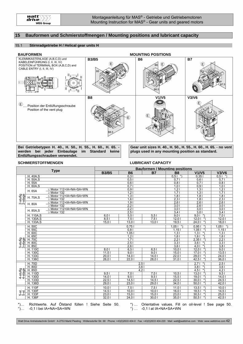
Montageanleitung für MAS® - Getriebe und Getriebemotoren Mounting Instruction for MAS® - Gear units and geared motors
Watt Drive Antriebstechnik GmbH ·A-2753 Markt Piesting ·Wöllersdorfer Str. 68 ·Phone: +43(0)2633 404-0 · Fax: +43(0)2633 404-220 · Mail: [email protected] · Web: www.wattdrive.com 42
15 Bauformen und Schmierstoffmengen / Mounting positions and lubricant capacity
Stirnradgetriebe H / Helical gear units H
BAUFORMEN MOUNTING POSITIONS KLEMMKASTENLAGE (A,B,C,D) und KABELEINFÜHRUNG (I, II, III, IV) POSITION of TERMINAL BOX (A,B,C,D) and CABLE ENTRY (I, II, III, IV)
B3/B5
B6
B7
… Position der Entlüftungsschraube Position of the vent plug
B8
V1/V5
V3/V6
Bei Getriebetypen H. 40., H. 50., H. 55., H. 60., H. 65. - werden bei jeder Einbaulage im Standard keine Entlüftungsschrauben verwendet.
Gear unit sizes H. 40., H. 50., H. 55., H. 60., H. 65. - no vent plugs used in any mounting position as standard.
SCHMIERSTOFFMENGEN LUBRICANT CAPACITY
Type Bauformen / Mounting positions B3/B5 B6 B7 B8 V1/V5 V3/V6
2-st
ufig
2-
stag
e
H. 40A,S 0,3 l 0,5 l °) 0,35 l 0,5 l °) H. 50A,S 0,5 l 0,7 l 0,6 l 0,7 l H. 55A 0,6 l 0,8 l 0,7 l 0,8 l H. 60A,S 0,7 l 1,0 l 0,9 l 1,0 l
H. 65A Motor 112+IA+NA+SA+WN 0,9 l 1,2 l 1,3 l 1,2 l Motor 132 1,2 l 1,7 l 1,3 l 1,7 l
H. 70A,S Motor 112+IA+NA+SA+WN 1,3 l 1,8 l 1,8 l 1,8 l Motor 132 1,6 l 2,3 l 1,8 l 2,3 l
H. 80A Motor 112+IA+NA+SA+WN 1,9 l 2,6 l 2,6 l 2,6 l Motor 132 2,2 l 3,0 l 2,6 l 3,0 l
H. 85A,S Motor 112+IA+NA+SA+WN 2,2 l 3,0 l 3,0 l 3,0 l Motor 132 2,5 l 3,4 l 3,0 l 3,4 l
H. 110A,S 6,0 l 5,5 l 5,5 l 9,0 l 9,0 l *) 7,0 l H. 130A,S 8,5 l 7,5 l 7,5 l 12,0 l 12,0 l *) 12,0 l H. 133A,S 15,0 l 13,0 l 13,0 l 19,5 l 24,0 l *) 18,0 l
3-st
ufig
3-
stag
e
H. 50C 0,75 l 1,05 l °) 0,95 l *) 1,05 l °) H. 55C 0,8 l 1,15 l 1,05 l *) 1,15 l H. 60C 1,05 l 1,3 l 1,3 l *) 1,3 l H. 65C 1,2 l 1,6 l 1,6 l *) 1,6 l H. 70C 1,7 l 2,2 l 2,35 l *) 2,2 l H. 80C 2,5 l 3,3 l 3,6 l *) 3,3 l H. 85C 2,6 l 3,6 l 4,0 l *) 3,8 l H. 110C 8,0 l 6,5 l 6,5 l 10,0 l 12,0 l *) 9,0 l H. 130C 11,5 l 9,0 l 9,0 l 15,0 l 17,0 l *) 13,5 l H. 133C 20,0 l 14,0 l 14,0 l 22,0 l 29,0 l *) 24,0 l H. 136C 26,0 l 22,0 l 28,0 l 31,0 l 42,5 l *) 36,0 l
4-st
ufig
4-
stag
e
H. 70D 2,5 l 2,7 l *) 2,5 l H. 80D 3,6 l 3,8 l *) 3,6 l H. 85D 4,2 l 4,5 l *) 4,2 l H. 110D 9,5 l 7,0 l 7,0 l 10,5 l 13,0 l *) 9,5 l H. 130D 14,0 l 9,5 l 9,5 l 15,5 l 19,0 l *) 14,0 l H. 133D 22,5 l 14,5 l 14,5 l 22,5 l 30,0 l *) 24,5 l H. 136D 29,0 l 23,0 l 29,0 l 34,0 l 50,0 l *) 42,0 l
5-st
. 5-
st. H. 110F 10,0 l 7,5 l 7,5 l 11,0 l 13,5 l *) 10,0 l
H. 130F 14,5 l 10,0 l 10,0 l 16,0 l 18,5 l *) 14,5 l H. 133F 23,0 l 15,0 l 15,0 l 23,0 l 30,5 l *) 25,0 l H. 136F 32,0 l 24,0 l 30,0 l 35,0 l 50,5 l *) 42,5 l
*)… Richtwerte. Auf Ölstand füllen ! Siehe Seite 50. °)… -0,1 l bei IA+NA+SA+WN
*) … Orientative values. Fill on oil-level ! See page 50. °) … -0,1 l at IA+NA+SA+WN
IV III
E
B3
B5
EB6
B6.5
E
B7
B7.5
E
E
B8
B8.5
E
V1
V5
E
V6
V3

Montageanleitung für MAS® - Getriebe und Getriebemotoren Mounting Instruction for MAS® - Gear units and geared motors
Watt Drive Antriebstechnik GmbH ·A-2753 Markt Piesting ·Wöllersdorfer Str. 68 ·Phone: +43(0)2633 404-0 · Fax: +43(0)2633 404-220 · Mail: [email protected] · Web: www.wattdrive.com 43
Einstufige Stirnradgetriebe H / Single stage helical gear units H
BAUFORMEN MOUNTING POSITIONS KLEMMKASTENLAGE (A,B,C,D) und KABELEINFÜHRUNG (I, II, III, IV) POSITION of TERMINAL BOX (A,B,C,D) and CABLE ENTRY (I, II, III, IV)
B3/B5
B6
B7
… Position der Entlüftungsschraube Position of the vent plug
B8
V1/V5
V3/V6
Bei Getriebetypen H. 41E, H. 51E, H. 60E - werden bei jeder Einbaulage im Standard keine Entlüftungsschrauben verwendet.
Gear unit sizes H. 41E, H. 51E, H. 60E - no vent plugs used in any mounting position as standard.
SCHMIERSTOFFMENGEN LUBRICANT CAPACITY
Type Bauformen B3/B5 B6 B7 B8 V1/V5 V3/V6
1-st
ufig
1-
stag
e
H. 41E 0,35 l °) H. 51E 0,4 l °)
H. 60E Motor 112+IA+NA+SA+WN 0,5 l Motor 132 0,9 l 1,1 l
H. 70E Motor 112+IA+NA+SA+WN 1,0 l Motor 132 1,3 l 1,5 l
H. 80E Motor 112+IA+NA+SA+WN 1,5 l Motor 132 1,8 l 2,1 l
H. 110E 4,5 l 5,5 l 4,5 l 5,5 l *)
*)… Richtwerte. Auf Ölstand füllen ! Siehe Seite 50. °)… -0,1 l bei IA+NA+SA+WN
*) … Orientative values. Fill on oil-level ! See page 50. °) … -0,1 l at IA+NA+SA+WN
IV III
E
B3
B5E
B6
B6.5
E
B7
B7.5
E
E
B8
B8.5
E
V1
V5
E
V6
V3

Montageanleitung für MAS® - Getriebe und Getriebemotoren Mounting Instruction for MAS® - Gear units and geared motors
Watt Drive Antriebstechnik GmbH ·A-2753 Markt Piesting ·Wöllersdorfer Str. 68 ·Phone: +43(0)2633 404-0 · Fax: +43(0)2633 404-220 · Mail: [email protected] · Web: www.wattdrive.com 44
Aufsteckgetriebe A / Shaft mounted gear units A
BAUFORMEN MOUNTING POSITIONS KLEMMKASTENLAGE (1,2,3,4) und KABEL- EINFÜHRUNG (I, II, III, IV) POSITION of TERMINAL BOX (1,2,3,4) and CABLE ENTRY (I, II, III, IV)
H3..
H4..
H1..
… Position der Entlüftungsschraube Position of the vent plug
H2..
V5..
V6..
Bei Getriebetypen A.. 46., A.. 56., A.. 66. - werden bei jeder Einbaulage im Standard keine Entlüftungsschrauben verwendet.
Ausnahme A.. 66C bei der Bauform V6. Hier wird eine Entlüftungsschraube verwendet.
Gear unit sizes A.. 46., A.. 56., A.. 66.- no vent plugs used in any mounting position as standard.
Exception A.. 66C for the mounting position V6. For this gear unit a vent plug must be used.
SCHMIERSTOFFMENGEN LUBRICANT CAPACITY
Type Bauformen / Mounting positions H1 H2 H3 V6 H4 V5
2-st
ufig
2-
stag
e
A.. 46A,S 0,9 l 1,05 l 1,1 l A.. 56A,S 0,9 l 1,3 l 1,5 l 1,3 l
A.. 66A,S Motor 112+IA+NA+SA+WN 1,8 l 2,7 l 3,3 l 2,7 l Motor 132 2,2 l 3,3 l 3,3 l 3,3 l
A.. 76A,S Motor 112+IA+NA+SA+WN 3,1 l 4,5 l 5,5 l 4,5 l Motor 132 3,4 l 5,1 l 5,5 l 5,1 l
A.. 86A,S Motor 112+IA+NA+SA+WN 6,0 l 9,0 l 10,9 l 9,0 l Motor 132 6,4 l 9,8 l 10,9 l 9,8 l
3-st
. 3-
st A.. 56C 1,1 l 1,7 l 1,8 l *) 1,7 l
A.. 66C 2,0 l 3,4 l 3,8 l *) 3,4 l A.. 76C 3,2 l 5,5 l 6,1 l *) 5,5 l A.. 86C 6,0 l 10,0 l 11,9 l *) 10,0 l
4-.
4-. A.. 76D 3,5 l 6,2 l 6,5 l *) 6,2 l
A.. 86D 6,2 l 11,0 l 12,2 l *) 11,0 l
*)… Richtwerte. Auf Ölstand füllen ! Siehe Seite 50. *) … Orientative values. Fill on oil-level ! See page 50.
IV III
EE
E
E
EE
E

Montageanleitung für MAS® - Getriebe und Getriebemotoren Mounting Instruction for MAS® - Gear units and geared motors
Watt Drive Antriebstechnik GmbH ·A-2753 Markt Piesting ·Wöllersdorfer Str. 68 ·Phone: +43(0)2633 404-0 · Fax: +43(0)2633 404-220 · Mail: [email protected] · Web: www.wattdrive.com 45
Flachgetriebe F / Parallel shaft gear units F
BAUFORMEN MOUNTING POSITIONS KLEMMKASTENLAGE (1,2,3,4) und KABEL- EINFÜHRUNG (I, II, III, IV) POSITION of TERMINAL BOX (1,2,3,4) and CABLE ENTRY (I, II, III, IV)
H3..
H4..
H1..
… Position der Entlüftungsschraube Position of the vent plug
H2..
V5.
V6..
Bei allen Getriebetypen werden bei jeder Einbaulage im Standard Entlüftungsschrauben verwendet.
All parallel shaft gear units have vent plugs in all mounting positions as standard.
SCHMIERSTOFFMENGEN LUBRICANT CAPACITY
Type Bauformen / mounting positions H1 H2 H3 V5 H4 V6
2-s
t. F.. 111A,S 8,0 l 11,0 l 14,0 l 14,0 l *) F.. 131A,S 12,0 l 17,0 l 21,0 l 21,0 l *)
3- F.. 137A 32,0 l 39,0 l 47,0 l *)
3-s
t. F.. 111C 9,0 l 14,0 l 15,0 l 17,0 l *) F.. 131C 13,0 l 23,0 l 23,0 l 26,0 l *)
4- F.. 137C 33,0 l 46,0 l 41,0 l 41,0 l 51,5 l *)
4-s
t. F.. 111D 9,5 l 15,0 l 14,0 l 15,4 l 17,4 l *) F.. 131D 13,5 l 25,0 l 23,5 l 24,0 l 27,0 l *)
5- F.. 137D 34,0 l 49,0 l 42,0 l 52,5 l *)
5-s
t. F.. 111F 10,0 l 15,5 l 14,5 l 16,0 l 18,0 l *) F.. 131F 14,0 l 25,5 l 24,0 l 24,5 l 27,5 l *)
*)… Richtwerte. Auf Ölstand füllen ! Siehe Seite 50. *) … Orientative values. Fill on oil-level ! See page 50.
IV III
E E
E
E
E
E
E
Ö

Montageanleitung für MAS® - Getriebe und Getriebemotoren Mounting Instruction for MAS® - Gear units and geared motors
Watt Drive Antriebstechnik GmbH ·A-2753 Markt Piesting ·Wöllersdorfer Str. 68 ·Phone: +43(0)2633 404-0 · Fax: +43(0)2633 404-220 · Mail: [email protected] · Web: www.wattdrive.com 46
Kegelstirnradgetriebe K40 - K75 / Helical bevel gear units K40 - K75
BAUFORMEN MOUNTING POSITIONS KLEMMKASTENLAGE (1,2,3,4) und KABEL- EINFÜHRUNG (I, II, III, IV) POSITION of TERMINAL BOX (1,2,3,4) and CABLE ENTRY (I, II, III, IV)
H3..
H4..
H5..
… Position der Entlüftungsschraube Position of the vent plug
H6..
V1..
V2..
Bei Getriebetypen K.. 40., K.. 50., K.. 60. - werden bei jeder Einbaulage im Standard keine Entlüftungsschrauben verwendet.
Gear unit sizes K.. 40., K.. 50., K.. 60. - no vent plugs used in any mounting position as standard.
SCHMIERSTOFFMENGEN LUBRICANT CAPACITY
Type Bauformen / Mounting positions H3 H4 V1 V2 H5 H6
2-st
ufig
2-
stag
e
K.. 40A 0,7 l 1,0 l K.. 50A 0,8 l 1,2 l 1,25 l
K.. 60A Motor 112+IA+NA+SA+WN 1,3 l 2,0 l 2,1 l Motor 132 1,6 l 2,3 l 2,1 l
K.. 70A Motor 112+IA+NA+SA+WN 2,3 l 3,9 l 2,6 l 4,1 l Motor 132 2,8 l 4,1 l 3,2 l 4,1 l
K.. 75A Motor 112+IA+NA+SA+WN 3,0 l 5,0 l 3,0 l 5,5 l Motor 132 3,4 l 5,3 l 3,6 l 5,5 l
3-st
. 3-
st. K.. 50C 1,0 l 1,5 l 1,6 l *)
K.. 60C 1,5 l 2,4 l 2,6 l *) K.. 70C 2,7 l 4,4 l 3,0 l 4,6 l *) K.. 75C 3,4 l 5,8 l 3,4 l 6,2 l *)
4-s.
4.
s.
K.. 70D 3,0 l 4,8 l 3,3 l 5,0 l *) K.. 75D 3,7 l 6,2 l 3,7 l 6,4 l *)
*)… Richtwerte. Auf Ölstand füllen ! Siehe Seite 50. *) … Orientative values. Fill on oil-level ! See page 50.
IV III E
E
E
E
E
EE

Montageanleitung für MAS® - Getriebe und Getriebemotoren Mounting Instruction for MAS® - Gear units and geared motors
Watt Drive Antriebstechnik GmbH ·A-2753 Markt Piesting ·Wöllersdorfer Str. 68 ·Phone: +43(0)2633 404-0 · Fax: +43(0)2633 404-220 · Mail: [email protected] · Web: www.wattdrive.com 47
Kegelstirnradgetriebe K77 - K139 / Helical bevel gear units K77 - K139
BAUFORMEN MOUNTING POSITIONS KLEMMKASTENLAGE (1,2,3,4) und KABEL- EINFÜHRUNG (I, II, III, IV) POSITION of TERMINAL BOX (1,2,3,4) and CABLE ENTRY (I, II, III, IV)
H3..
H4..
H5..
… Position der Entlüftungsschraube Position of the vent plug
H6..
V1..
V2..
Bei allen Getriebetypen werden bei jeder Einbaulage im Standard Entlüftungsschrauben verwendet.
All parallel shaft gear units have vent plugs in all mounting positions as standard.
SCHMIERSTOFFMENGEN LUBRICANT CAPACITY
Type Bauformen / Mounting positions H3 H4 V1 V2 H5 H6
3-st
ufig
3-
stag
e
K.. 77A Motor 112+IA+NA+SA+WN 2,6 l 3,5 l 2,6 l 3,5 l 5,0 l Motor 132 2,8 l 4,1 l 2,8 l 4,1 l 5,0 l
K.. 80A Motor 112+IA+NA+SA+WN 4,5 l 6,4 l 4,5 l 5,8 l 8,8 l Motor 132 4,7 l 7,0 l 4,7 l 6,4 l 8,8 l
K.. 86A Motor 112+IA+NA+SA+WN 7,6 l 10,7 l 7,6 l 9,6 l 15,5 l *) Motor 132 7,9 l 11,3 l 7,9 l 10,2 l 15,5 l *)
K.. 110A 13,0 l 19,0 l 13,0 l 18,0 l 23,5 l *) K.. 136A 30,0 l 44,0 l 30,0 l 39,0 l 61,0 l *) K.. 139A 40,0 l 53,0 l 45,0 l 48,0 l 76,0 l *)
4-st
ufig
4-
stag
e K.. 77C 3,8 l 3,0 l 3,9 l 5,7 l *)
K.. 80C 6,7 l 4,8 l 6,2 l 9,7 l *) K.. 86C 11,0 l 8,0 l 10,0 l 16,2 l *) K.. 110C 17,0 l 21,0 l 14,0 l 20,0 l 27,5 l *) K.. 136C 40,0 l 47,0 l 32,0 l 42,0 l 67,0 l *) K.. 139C 48,0 l 56,0 l 48,0 l 52,0 l 81,0 l *)
5-st
ufig
5-
stag
e K.. 77D 4,4 l 3,5 l 4,4 l 5,9 l *)
K.. 80D 7,0 l 5,3 l 6,7 l 9,7 l *) K.. 86D 11,2 l 8,5 l 10,5 l 16,0 l *) K.. 110D 21,0 l 22,5 l 15,0 l 22,0 l 28,5 l *) K.. 136D 45,0 l 50,0 l 33,0 l 45,0 l 68,0 l *) K.. 139D 56,0 l 59,0 l 50,0 l 55,0 l 82,0 l *)
*)… Richtwerte. Auf Ölstand füllen ! Siehe Seite 50. *) … Orientative values. Fill on oil-level ! See page 50.
IV IIIE
E E
E
E
EE
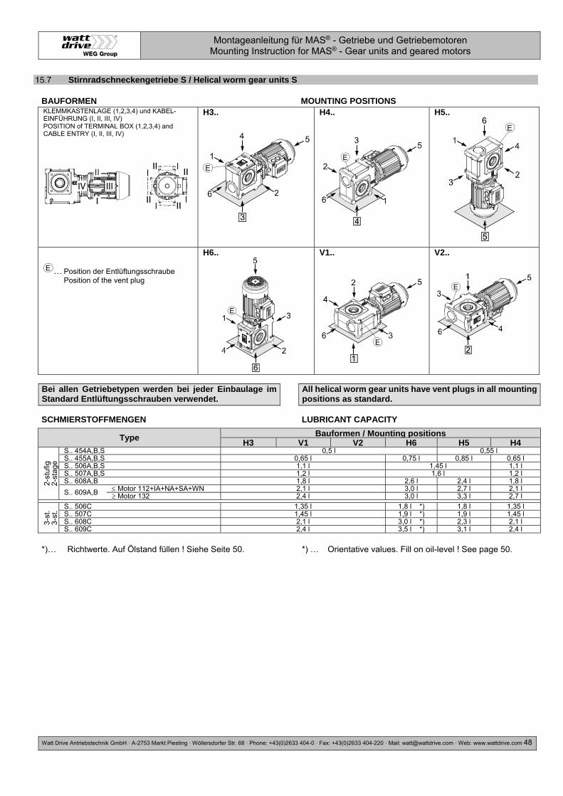
Montageanleitung für MAS® - Getriebe und Getriebemotoren Mounting Instruction for MAS® - Gear units and geared motors
Watt Drive Antriebstechnik GmbH ·A-2753 Markt Piesting ·Wöllersdorfer Str. 68 ·Phone: +43(0)2633 404-0 · Fax: +43(0)2633 404-220 · Mail: [email protected] · Web: www.wattdrive.com 48
Stirnradschneckengetriebe S / Helical worm gear units S
BAUFORMEN MOUNTING POSITIONS KLEMMKASTENLAGE (1,2,3,4) und KABEL- EINFÜHRUNG (I, II, III, IV) POSITION of TERMINAL BOX (1,2,3,4) and CABLE ENTRY (I, II, III, IV)
H3..
H4..
H5..
… Position der Entlüftungsschraube Position of the vent plug
H6..
V1..
V2..
Bei allen Getriebetypen werden bei jeder Einbaulage im Standard Entlüftungsschrauben verwendet.
All helical worm gear units have vent plugs in all mounting positions as standard.
SCHMIERSTOFFMENGEN LUBRICANT CAPACITY
Type Bauformen / Mounting positions H3 V1 V2 H6 H5 H4
2-st
ufig
2-
stag
e
S.. 454A,B,S 0,5 l 0,55 l S.. 455A,B,S 0,65 l 0,75 l 0,85 l 0,65 l S.. 506A,B,S 1,1 l 1,45 l 1,1 l S.. 507A,B,S 1,2 l 1,6 l 1,2 l S.. 608A,B 1,8 l 2,6 l 2,4 l 1,8 l
S.. 609A,B Motor 112+IA+NA+SA+WN 2,1 l 3,0 l 2,7 l 2,1 l Motor 132 2,4 l 3,0 l 3,3 l 2,7 l
3-st
. 3-
st. S.. 506C 1,35 l 1,8 l *) 1,8 l 1,35 l
S.. 507C 1,45 l 1,9 l *) 1,9 l 1,45 l S.. 608C 2,1 l 3,0 l *) 2,3 l 2,1 l S.. 609C 2,4 l 3,5 l *) 3,1 l 2,4 l
*)… Richtwerte. Auf Ölstand füllen ! Siehe Seite 50. *) … Orientative values. Fill on oil-level ! See page 50.
IV III
E
E
E
E
E
E
E

Montageanleitung für MAS® - Getriebe und Getriebemotoren Mounting Instruction for MAS® - Gear units and geared motors
Watt Drive Antriebstechnik GmbH ·A-2753 Markt Piesting ·Wöllersdorfer Str. 68 ·Phone: +43(0)2633 404-0 · Fax: +43(0)2633 404-220 · Mail: [email protected] · Web: www.wattdrive.com 49
Kegelflachgetriebe C / Angle parallel shaft gear units C
BAUFORMEN MOUNTING POSITIONS KLEMMKASTENLAGE (1,2,5,6) und KABELEINFÜHRUNG (I, II, III, IV) POSITION of TERMINAL BOX (1,2,5,6) and CABLE ENTRY (I, II, III, IV)
… Position der Entlüftungsschraube Position of the vent plug
H3..
H4..
Vorsatzgetriebelage Seite 1, 2, 5 oder 6 Position of primary gear unit towards side 1, 2, 5 or 6
H1..
H2..
V5..
V6..
Bei allen Getriebetypen werden bei jeder Einbaulage im Standard Entlüftungsschrauben verwendet.
All angle parallel shaft gear units have vent plugs in all mounting positions as standard.
SCHMIERSTOFFMENGEN LUBRICANT CAPACITY
Type Bauformen / Mounting positions H1 H2 V5 H3 H4 V6
3-st
ufig
3-
stag
e
C.. 70A Motor 112+IA+NA+SA+WN 2,2 l 3,0 l 2,4 l 2,2 l Motor 132 2,6 l 3,0 l 3,0 l 2,6 l
C.. 80A Motor 112+IA+NA+SA+WN 3,7 l 5,6 l 4,0 l 3,7 l Motor 132 4,2 l 5,6 l 4,6 l 4,2 l
C.. 85A Motor 112+IA+NA+SA+WN 7,2 l 10,5 l 7,2 l Motor 132 7,7 l 10,5 l 7,7 l
C.. 110A 9,0 l 12,0 l 15,5 l *) 12,0 l C.. 130A 12,5 l 15,0 l 23,0 l *) 15,0 l
4-st
ufig
4-
stag
e C.. 70C 2,7 l 3,6 l *) 2,7 l
C.. 80C 5,6 l 6,5 l *) 5,6 l C.. 85C 9,5 l 11,5 l *) 9,5 l C.. 110C 15,0 l 19,5 l *) 15,0 l C.. 130C 21,0 l 28,0 l *) 21,0 l
5-st
ufig
5-
stag
e C.. 70D 3,6 l 3,9 l *) 3,6 l
C.. 80D 6,5 l 7,0 l *) 6,5 l C.. 85D 10,5 l 11,9 l *) 10,5 l C.. 110D 18,0 l 20,0 l *) 18,0 l C.. 130D 25,0 l 29,0 l *) 25,0 l
*)… Richtwerte. Auf Ölstand füllen ! Siehe Seite 50. *) … Orientative values. Fill on oil-level ! See page 50.
IV III
E
E
E
E
E
EE
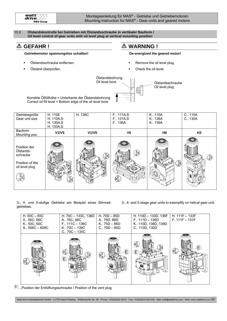
Montageanleitung für MAS® - Getriebe und Getriebemotoren Mounting Instruction for MAS® - Gear units and geared motors
Watt Drive Antriebstechnik GmbH ·A-2753 Markt Piesting ·Wöllersdorfer Str. 68 ·Phone: +43(0)2633 404-0 · Fax: +43(0)2633 404-220 · Mail: [email protected] · Web: www.wattdrive.com 50
Ölstandskontrolle bei Getrieben mit Ölstandsschraube in vertikaler Bauform / Oil level control of gear units with oil level plug at vertical mounting position
GEFAHR ! Getriebemotor spannungslos schalten!
Ölstandsschraube entfernen.
Ölstand überprüfen.
WARNING ! De-energized the geared motor!
Remove the oil level plug.
Check the oil level.
3-, 4- und 5-stufige Getriebe am Beispiel eines Stirnrad-getriebes.
3-, 4- and 5-stage gear units to exemplify on helical gear unit.
…Position der Entlüftungsschraube / Position of the vent plug E
Getriebegröße Gear unit size
H. 110E H. 110A,S H. 130A,S H. 133A,S
H. 136C F.. 111A,S F.. 131A,S F.. 136A
K.. 110A K.. 136A K.. 139A
C.. 110A C.. 130A
Bauform Mounting pos.
V1/V5 V1/V5 V6 H6 H3
Position der Ölstands-schraube Position of the oil level plug
H. 50C – 65C A.. 56C, 66C K.. 50C, 60C S.. 506C – 609C
H. 70C – 133C, 136D A.. 76C, 86C F.. 111C – 136C K.. 70C – 139C C.. 70C – 130C
H. 70D – 85D A.. 76D, 86D K.. 75D – 86D C.. 70D – 85D
H. 110D – 133D, 136F F.. 111D – 136D K.. 110D, 136D, 139D C.. 110D, 130D
H. 111F – 133F F. 111F – 131F
E
E EE
Korrekte Ölfüllhöhe = Unterkante der Ölstandsbohrung Correct oil fill level = Bottom edge of the oil level bore
Ölstandsbohrung Oil level bore Ölstandsschraube
Oil level plug

Montageanleitung für MAS® - Getriebe und Getriebemotoren Mounting Instruction for MAS® - Gear units and geared motors
Watt Drive Antriebstechnik GmbH ·A-2753 Markt Piesting ·Wöllersdorfer Str. 68 ·Phone: +43(0)2633 404-0 · Fax: +43(0)2633 404-220 · Mail: [email protected] · Web: www.wattdrive.com 51
16 Klemmenanschluss / Terminal board connection
Bemessungsspannung Serien 3A, 3B, 3C (IEC Baugrößen 63 bis 100) Rated voltage series 3A, 3B, 3C (IEC frame sizes 63 to 100)
Mögliche Schaltung Possible connection
Nennleistung PN Rated power PN
Erhöhte Leistung Increased rated power 1,2 x PN
Frequenzumrichterbetrieb Frequency inverter operation
Dreieck Delta
220 – 230 – 240 V bei/at 50 Hz 220 – 265 – 277 V bei/at 60 Hz
- 254 – 265 – 277 V bei/at 60 Hz
400 V, 87 Hz
Doppeldreieck Delta - Delta
110 – 115 – 120 V bei/at 50 Hz 110 – 132 – 138 V bei/at 60 Hz
- 127 – 132 – 138 V bei/at 60 Hz
230 V, 100 Hz
Stern (Grundschaltung) Star (Basic connection)
380 – 400 – 420 V bei/at 50 Hz 380 – 460 – 480 V bei/at 60 Hz
- 440 – 460 – 480 V bei/at 60 Hz
400 V, 100 Hz
Doppelstern Star Star
190 – 200 – 210 V bei/at 50 Hz 190 – 230 – 240 V bei/at 60 Hz
- 220 – 230 – 240 V bei/at 60 Hz
460 V, 120 Hz
Bemessungsspannungen Serien 3A, 3B, 3C (IEC Baugrößen 112 bis 315) Rated voltage series 3A, 3B, 3C (IEC frame sizes 112 to 315)
Mögliche Schaltung Possible connection
Nennleistung PN Rated power PN
Erhöhte Leistung Increased rated power 1,2 x PN
Frequenzumrichterbetrieb Frequency inverter operation
Dreieck (Grundschaltung) Delta (Basic connection)
380 – 400 – 420 V bei/at 50 Hz 380 – 460 – 480 V bei/at 60 Hz
- 440 – 460 – 480 V bei/at 60 Hz 400 V, 100 Hz
Doppeldreieck Delta - Delta
190 – 200 – 210 V bei/at 50 Hz 190 – 230 – 240 V bei/at 60 Hz
- 220 – 230 – 240 V bei/at 60 Hz
Stern Star
660 – 690 – (730) V bei/at 50 Hz 660 – (796) – (830) V bei/at 60 Hz
- (760) – (796) V bei/at 60 Hz 460 V, 120 Hz
Doppelstern Star - Star
330 – 346 – 365 V bei/at 50 Hz 330 – 400 – 415 V bei/at 60 Hz
- 380 – 400 – 415 V bei/at 60 Hz

Montageanleitung für MAS® - Getriebe und Getriebemotoren Mounting Instruction for MAS® - Gear units and geared motors
Watt Drive Antriebstechnik GmbH ·A-2753 Markt Piesting ·Wöllersdorfer Str. 68 ·Phone: +43(0)2633 404-0 · Fax: +43(0)2633 404-220 · Mail: [email protected] · Web: www.wattdrive.com 52
Das folgende Schaltbild gilt für Modulare Systemmotoren Baugröße 63 bis 315 der Serie 3A, 3B und 3C.
The following connection diagram is vaild for Modular System Motor frame size 63 up to 315. Motor series 3A, 3B and 3C.
Bild 19: Klemmenanschluss Motorserie 3A, 3B und 3C Fig. 19: Term. board connection – Motor series 3A, 3B and 3C
Tabelle 5: Anzugsmomente Table 5: Tightening torque
Gewinde Thread
Anzugsmoment Ma [Nm] Tightening torque Ma [Nm]
M4 0,7 - 1,0 M5 1,6 - 2,2 M6 2,2 - 3,5 M8 6 - 8
M10 10 - 14

Montageanleitung für MAS® - Getriebe und Getriebemotoren Mounting Instruction for MAS® - Gear units and geared motors
Watt Drive Antriebstechnik GmbH ·A-2753 Markt Piesting ·Wöllersdorfer Str. 68 ·Phone: +43(0)2633 404-0 · Fax: +43(0)2633 404-220 · Mail: [email protected] · Web: www.wattdrive.com 53
17 Optionale Motorzusatzeinrichtungen / Optional motor devices
Bremse, Inkrementalgeber, Temperaturwächter, Still-standsheizung, Fremdlüftung,… sind nur auf besondere Bestellung vorhanden.
Zusatzeinrichtungen sind nach den beiliegenden Schaltbildern anzuschließen.
Brake, encoder, temperature controller, anti condensation heating, forced ventilation,… are present only on special order.
Additional devices are to be connected after the valid wiring diagrams.
Stillstandsheizung / Anti-condensation heating
Bei besonderen Klimaverhältnissen z.B. bei starken Temperaturschwankungen oder bei stillstehenden Motoren in feuchter Atmosphäre kann eine Stillstandsheizung vorgesehen werden. Die Beschaltung des Heizelementes ist im Anschlusskasten des Motors ersichtlich.
GEFAHR ! Vor jedem Einschalten muss sichergestellt sein, dass die optionale Stillstandsheizung ausgeschaltet wird.
Under certain climatic conditions an anti- condensation heater may be required e.g. when there are great fluctuations in temperature or the motor is at rest in a humid atmosphere. For heater connection, see the motor terminal box.
WARNING ! Before energizing the motor, always make sure that the (optional) anti-condensation heating is switched off.
Kondenswasserbohrung / Drain
Bei Motoren, die starken Temperaturschwankungen oder extremen klimatischen Verhältnissen ausgesetzt sind, kann im Inneren Luftfeuchtigkeit kondensieren. In diesem Fall empfehlen wir eine optionale Kondeswasserbohrung.
VORSICHT ! Öffnen Sie in Abhängigkeit von den Umgebungs- und
Betriebsbedingungen den Kondenswasserstopfen zum Ablassen des Wassers. Stopfen anschließend wieder schließen.
Bei Motoren mit Kondenswasserbohrungen ist auf die richtige Einbaulage zu achten!
If motors are subject to great fluctuations in temperature or extreme climatic conditions, humid air can condense inside the machine. We recommend using a drain.
ATTENTION ! Open the drain in dependent of the environment and
operating condiions. Afterwards, close the drain plug.
Before installing motors with drain, check that the mounting position is correct.
Bild 20: Detail des Kondenswasserstopfens am Lagerschild. Fig. 20: Detail of the drain plug position on drive endshield.
Kondenswasserstopfen geschlossen. Rubber drain plug closed.
Kondenswasserstopfen geöffnet. Rubber drain plug open.

Montageanleitung für MAS® - Getriebe und Getriebemotoren Mounting Instruction for MAS® - Gear units and geared motors
Watt Drive Antriebstechnik GmbH ·A-2753 Markt Piesting ·Wöllersdorfer Str. 68 ·Phone: +43(0)2633 404-0 · Fax: +43(0)2633 404-220 · Mail: [email protected] · Web: www.wattdrive.com 54
Fremdlüfter / Forced cooling
VORSICHT ! Der Fremdlüfter muss nach beiliegendem Schaltbild
(siehe Anschlusskasten Fremdlüfter) an eine externe Versorgungsspannung angeschlossen werden.
Bei Betrieb des Motors an einem Frequenzumrichter darf der Fremdlüfter nicht an den Frequenzumrichter angeschlossen, sondern muss an eine EXTERNE Versorgungsspannung angeschlossen werden.
ATTENTION ! The forced cooling must be connected according to
wiring diagram (see in forced cooling terminal box).
If the motor is operated with a frequency inverter, it´s not allowed to connect the forced cooling on the frequency inverter. Connect the forced cooling to an EXTERNAL power supply.
IEC Baugröße IEC frame size
Phasen / Schaltung Phases / Connection
Spannungsbereich [V] Voltage range [V]
50 Hz 60 Hz
63 – 132 3~ / Stern 346 – 525 380 – 575 3~ / Dreieck 200 – 303 220 – 332 1~ / Delta Steinmetz 230 – 277 230 – 277
160 – 200 3~ / Stern 346 – 525 380 – 575 3~ / Dreieck 200 – 303 220 - 332 1~ / Delta Steinmetz 230 – 277 -
225 – 315 3~ / Stern 346 – 525 380 – 575 3~ / Dreieck 200 – 400 220 – 400
Sternschaltung Dreieckschaltung Delta Steinmetz Schaltung Star Connection Delta Connection Delta Steinmetz Connection
U1 = schwarz / black V1 = hellblau / light-blue W1 = braun/ / brown U2 = grün / green V2 = weiß / white W2 = gelb / yellow
Temperaturwächter Bimetallschalter “Öffner” (TH) / Temperature controller Bimetal switch “NC contact” (TH)
Temperaturwächter sind kleine Bimetallschalter, die beim Überschreiten der Ansprechtemperatur einen Kontakt öffnen oder schließen. Der Öffnungskontakt trennt den Erregerkreis des Motorschützes und die Spannungsversorgung des Motors wird damit getrennt.
Blockklemmenkennz. im Anschlusskasten: 2TB1 / 2TB2
Thermostats have small bimetallic strips that make or break a contact when the critical temperature is reached. The break contact opens the field circuit and disconnects the power supply to the motor.
Block terminal designation in the terminal box: 2TB1 / 2TB2
PTC Kaltleitertemperaturfühler (TF) / PTC Thermistor protection (TF)
Kaltleitertemperaturfühler sind Halbleiter, bei denen der ohmsche Widerstand bei Erreichen der Bemessungs-ansprechtemperatur extrem ansteigt.
Zusätzlich zu den Kaltleiterfühlern ist ein Auslösgerät notwendig. Das im Auslösegerät befindliche Relais mit einem Wechselkontakt kann nach Bedarf zum Unterbrechen des Erregerkreises des Motorschützers oder zum Auslösen eines Warnsignals verwendet werden.
Blockklemmenkennz. im Anschlusskasten: 2TP1 / 2TP2
PTC thermistors are semi-conductors whose electrical resistance increases dramatically when the critical temperature is reached. In addition to the PTC thermistor, a control unit is also required. The relay in the tripping unit has a changeover contact, which can either be used to open the excitation circuit in the motor contactor or trigger a warning signal.
Block terminal designation in the terminal box: 2TP1 / 2TP2

Montageanleitung für MAS® - Getriebe und Getriebemotoren Mounting Instruction for MAS® - Gear units and geared motors
Watt Drive Antriebstechnik GmbH ·A-2753 Markt Piesting ·Wöllersdorfer Str. 68 ·Phone: +43(0)2633 404-0 · Fax: +43(0)2633 404-220 · Mail: [email protected] · Web: www.wattdrive.com 55
Bremse / Brake
Die Einscheiben-Federdruckbremse wird elektrisch gelüftet. Der Bremsvorgang erfolgt mechanisch nach Ausschalten der Spannung.
Die Bremsen sind bei der Lieferung auf das Bremsmoment eingestellt.
Anschluss der Bremse:
Bremsenansteuerung nach jeweils beiliegendem Schaltbild anschließen.
Wartung:
Die Federdruckbremsen sind nahezu wartungsfrei. Der Bremsluftspalt “a” ist in bestimmten Zeitabständen zu überprüfen, um ein sicheres Lüften der Bremse zu gewährleisten. Ein erforderliches Einstellen des Luftspaltes “a” muß nach Tabelle 6 erfolgen.
The single-disc brake is released electrically. The brake is applied mechanically when the voltage is switched off.
At delivering the brakes are adjusted to the brake torque.
Connecting the brake:
Connect the brake control system according to the circuit diagram supplied with the brake.
Maintenance:
The spring-loaded brakes hardly need any maintenance. The air gap "a" must be checked periodically to ensure safe brake release. Adjust air gap "a" to the figures given in Table 6 below if necessary.
Tabelle 6: Bremsenluftspalt Table 6: Brake air gap
Nachstellen des Bremsluftspaltes (siehe Bild 21):
Lösen Sie die drei Befestigungsschrauben (9) eine halbe Umdrehung.
Drehen Sie gegen den Uhrzeigersinn die Hülsenschrauben (6) in den Magnetkörper (8) hinein.
Drehen Sie im Uhrzeigersinn die drei Befestigungs-schrauben (9) soweit, bis der Nennluftspalt, (siehe Tabelle 6, Seite 55) zwischen dem Magnetkörper (8) und Ankerscheibe (7) erreicht ist.
Schrauben Sie die drei Hülsenschrauben (6) wieder im Uhrzeigersinn bis zur festen Anlage aus dem Magnetkörper (8) heraus und ziehen Sie die Befestigungsschrauben (9) nach. Kontrollieren Sie mit mit einer Fühlerlehre den Luftspalt “a” auf Gleichmäßigkeit und korrigieren Sie diesen gegebenenfalls.
Adjustment of the air gap (see Fig. 21):
1. Loosen the three fixing bolts (9) in a half turn.
2. Turn the screw sleeves (6) counter-clockwise into the magnetic case (8).
3. Turn the three fixing bolts (9) clockwise until the nominal air gap (see tab.6, page 55) between the magnetic case (8) and armature disc (7) is reached.
4. Turn the three sleeve screws (6) again clockwise out of the magnetic case (8) and retighten the fixing bolts (9). Control the air gap “a” with a feeler gauge on evenness and make a correction if necessary.
Bremsmoment Brake torque
[Nm] 2 5 10 20 40 60 100 150 250 400 1000
a (normal) a (maximum)
[mm] [mm]
0,2 0,6
0,2 0,6
0,2 0,7
0,3 0,8
0,3 0,9
0,3 1
0,4 1,1
0,4 1,1
0,5 1,2
0,5 1,2
0,6 1,3

Montageanleitung für MAS® - Getriebe und Getriebemotoren Mounting Instruction for MAS® - Gear units and geared motors
Watt Drive Antriebstechnik GmbH ·A-2753 Markt Piesting ·Wöllersdorfer Str. 68 ·Phone: +43(0)2633 404-0 · Fax: +43(0)2633 404-220 · Mail: [email protected] · Web: www.wattdrive.com 56
Bild 21: Explosionsdarstellung Bremsenanbau Fig. 21: Exploded view brake
Bremslagerschild Passfeder Welle Mitnehmer-Zahnnabe Handlüftbügel (optional) Hohlschrauben Ankerscheibe Magnetkörper Zylinderschrauben mit Innensechskant
Passfeder Bremswellenverlängerung Lüfterflügel Sicherungsring Zylinderschrauben mit Innensechskant Befestigungsschrauben Lüfterhaube Lüfterhaube Bremsausführung
Brake-endshield Key Shaft Gear hub Hand release bracket (optional) Hollow screws Armature disc Magnetic case Socket head cap screw
Key Brake shaft adapter Fan Retaining ring Socket head cap screw Fan cover screw Fan cover brake execution
17.6.1 Handlüftung / Manual brake release
Dient zum mechanischen Lüften der Bremse bei Stromausfall. Durch betätigen des Handlüftungshebels wird die Ankerscheibe angezogen und die Bremse entlüftet.
VORSICHT ! An der Einstellung der Handlüftung darf aus Sicherheitsgründen nichts verändert werden.
Is used to lift the brake when in case of a loss of power supply. By pressing the lever, the anchor plate is pulled to the magnet and the brake is lifted.
ATTENTION ! For safety reasons the adjustment of the manual release must not be changed.
17.6.2 Arretierungvorrichung des Handhebels / Locking device for the hand release bracket
Die Handlüftung kann im Servicefall mit einer Arretierung fixiert werden.
VORSICHT ! Der Motor darf erst nach Deaktivierung der Arretiervorrichtung in Betrieb genommen werden.
In case of service the manual brake release can be fixed with a locking device.
ATTENTION ! The motor only has to be taken into operation after having deactivated the locking device.

Montageanleitung für MAS® - Getriebe und Getriebemotoren Mounting Instruction for MAS® - Gear units and geared motors
Watt Drive Antriebstechnik GmbH ·A-2753 Markt Piesting ·Wöllersdorfer Str. 68 ·Phone: +43(0)2633 404-0 · Fax: +43(0)2633 404-220 · Mail: [email protected] · Web: www.wattdrive.com 57
17.6.3 Gleichrichter / Rectifier
Serienmäßig werden Bremsmotoren mit angeschlossenem Gleichrichter für wechselstromseitiges Schalten geliefert.
Für gleichstromseitiges Schalten ist die Brücke zwischen den Klemmen 5 und 6 zu entfernen und ein Schaltkontakt anzuschließen.
VORSICHT ! Der Motor darf nur mit angeschlossener Bremse eingeschaltet werden. (Prüfen!)
Brake motors will be delivered as standard with connected rectifier for AC-side switching.
For DC-side switching the bridge between terminals 5 and 6 must be removed and a switching contact must be connected.
ATTENTION ! Start-up of motor only with connecting brake. (Check!)
Bild 22: Gleichrichter Fig. 22: Rectifier
Stromversorgung:
Die Gleichstrom-Bremsspule wird normalerweise über einen im Motor-Klemmkasten eingebauten Gleichrichter gespeist. Zum Schutz gegen Überspannungen sind die Gleichrichter mit Varistoren beschaltet. Maximale Umgebungstemperatur +80°C.
Bei Schaltfrequenz über 1/s wegen Gleichrichter-Belastung rückfragen!
Der Anschluss des Bremssystems erfolgt über einen im Klemmenkasten eingebauten Gleichrichter entsprechend dem jeweils beigefügten Schaltbild.
Einweggleichrichter (Standard) - Anschluss:
Wechselspannung 100% z.B. 400 V~
Gleichspannung 45% z.B. 180 V=
Brückengleichrichter - Anschluss:
Wechselspannung 100% z.B. 230 V~
Gleichspannung 90% z.B. 205 V=
VORSICHT ! Bei Betrieb eines Bremsmotors mit Frequenzumrichter ist die Bremsspule an eine externe Spannungsversorgung anzuschließen.
Power supply:
The DC brake coil is normally supplied with power from a rectifier installed in the motor terminal box. The rectifiers are equipped with varistors to protect them against overvoltage. Max. ambient temperature for rectifiers is +80°C.
For starting frequency above 1/s, contact us for rectifier loading capacity!
The braking system is connected with a rectifier installed in the terminal box in accordance with the enclosed circuit diagram.
Half-wave rectifier (standard version) - Connection:
AC voltage 100% e.g. 400 V a.c
DC voltage 45% z.B. 180 V d.c.
Bridge rectifier - Connection:
AC voltage 100% e.g. 230 V a.c
DC voltage 90% z.B. 205 V d.c.
ATTENTION ! If a brake motor is operated with a frequency converter, connect the brake coil to an external power supply.
~~1 2 3 4 5 6
-+
Kontakt für DC-Schaltung Contact for DC switching
Bremse Brake
Anschluss am Klemmbrett (AC, V~) Connection to terminal board (AC, V~)

Montageanleitung für MAS® - Getriebe und Getriebemotoren Mounting Instruction for MAS® - Gear units and geared motors
Watt Drive Antriebstechnik GmbH ·A-2753 Markt Piesting ·Wöllersdorfer Str. 68 ·Phone: +43(0)2633 404-0 · Fax: +43(0)2633 404-220 · Mail: [email protected] · Web: www.wattdrive.com 58
Drehgeber / Encoder
Dieser Geber ist ein Präzisionsmessgerät. Die Angaben und Hinweise in den Datenblättern sind zu beachten um eine problemlose Funktion des Gebers zu gewährleisten und die Garantieleistung aufrecht zu erhalten.
Bitte beachten sie unbedingt folgende Punkte:
Der Drehgeber darf weder teilweise noch ganz zerlegt oder modifiziert werden.
Die Welle darf nicht nachträglich bearbeitet (schleifen, bohren, sägen, usw) werden. Die Genauigkeit des Gebers und die Zuverlässigkeit von Lager und Dichtung nehmen sonst Schaden.
Das Gerät niemals mit dem Hammer ausrichten.
Schlagbelastungen unbedingt vermeiden.
Drehgeberwelle nicht über die in den Datenblättern angegebenen Werte belasten.
Drehgeber und Antriebsgerät nicht an Wellen und Flanschen starr miteinander verbinden.
Angebaute Drehgeber keinesfalls als Hilfe zum Heben der Arbeitsmaschine benützen.
Angebaute Drehgeber keinesfalls als Tritthilfe benützen.
This encoder is a precision measuring instrument. Always observe the information and instructions of the datasheet to nsure trouble-free function and to maintain warranty claims.
Please observe absolutely the following points:
It is not permissible to dismantle the encoder entirely or in part or to modify it.
Do not alter the shaft (by grinding, sawing, drilling, etc.), otherwise the accuracy of the encoder and the reliability of bearing and seal will suffer.
Never align the instrument with a hammer.
It is imperative to avoid impact loads.
Observe maximal radial and axial loads to the encodershaft under any circumstances.
Do not connect encoder and drive rigidly to one another at shafts and flanges.
Never use the assembled encoder to lift the drive-unit.
Never step onto the encoder.
Technische Daten Standardgeber: Technical Data Standard Encoder:
Type Versorgungsspannung Voltage
Impulszahl Pulses
Ausgangssignalpegel Output signal
Kübler 5020 10 – 30 V 1024 HTL
Kübler A02H (Heavy Duty) 10 – 30 V 1024 HTL
Belegung Standardgeber:
Pin definition standard encoder:
SIGNAL GRD BINV +UB Sens
0 0INV A AINV - B - 0 V 0 V
Sens +UB UAS
KÜ
BLE
R
M23 X 1 Flanschdose / Can
1 2 3 4 5 6 7 8 9 10 11 12 -
PVC-Kabel / cable PH PK BU/ RD
BU RD GN YE - GY - WH GY/PK BN -
PUR-Kabel /cable HT-Kabel / cable
PH PK BN* BU RD GN YE - GY - WH° WH* BN° -

Montageanleitung für MAS® - Getriebe und Getriebemotoren Mounting Instruction for MAS® - Gear units and geared motors
Watt Drive Antriebstechnik GmbH ·A-2753 Markt Piesting ·Wöllersdorfer Str. 68 ·Phone: +43(0)2633 404-0 · Fax: +43(0)2633 404-220 · Mail: [email protected] · Web: www.wattdrive.com 59
Code Farbe / Colour Code Farbe / Colour Code Farbe / Colour Code Farbe / Colour Code Farbe / Colour
BK Schwarz Black
GN Grün Green
RD Rot Red
YE Gelb Yellow
PH
Schirm liegt am Steckergehäuse an Shield attached to connector housing
BN Braun Brown
GY Grau Grey
VT Violett Violet
* Dünnes Kabel Thin cable
BU Blau Blue
PK Rosa Pink
WH Weiß White
° Dickes Kabel Thick cable
18 Tabelle für Schraubenanzugsmomente / Table of Tightening Torques
Gilt für Schrauben-Festigkeitsklasse 8.8:
Abtriebsflansche
Drehmomentstützen
Fußleisten
Eingangsdeckeln
Abdeckkappen
Motorbefestigung
Valid for screw property class 8.8 :
Output flange
Torque arms
Foot plates
Input cover
Protection caps
Motor mounting
Tabelle 7: Schraubenanzugsmomente
Table 7: Tightening Torques
19 Entsorgung / Disposal
Beachten Sie bei der Entsorgung die gültigen nationalen Vorschriften.
Öle und Fette bzw. öl- und fetthaltige Abfälle stellen ein hohes Gefahrenpotential für die Umwelt dar. Sorgen Sie deshalb für eine fachgerechte Entsorgung !
Mind the current national regulations for the disposal.
Oils and grease or oil- and grease containing wastes make up a high hazardous potential for the environment. Thus ensure a professional disposal!
Getriebemotorenteile Material Getriebegehäuse, Gehäuseteile (Eingangsdeckel, Adapter, Flansche,…)
Grauguss Ausnahme: K.. 40. Aluminium
Getriebeinnenteile (Zahnräder, Passfedern, Wellen, ) Stahl Schneckenräder Bronze Wellendichtringe Elastomer mit Stahl Flachdichtungen Asbestfrei Getriebeöl Additiviertes Mineralöl Getriebeöl synthetisch Polyglykolöl Motorwicklung Kupfer
Anzugsmoment Ma [Nm] - Toleranz +10% Tightening torque Ma [Nm] - tolerance +10%
Gewinde Thread
Schrauben- Festigkeitsklasse
Screw property class 8.8
Schrauben- Festigkeitsklasse
Screw property class 10.9
Schrauben- Festigkeitsklasse
Screw property class 12.9
M5 5,5 8,0 10 M6 10 14 18 M8 25 33 43
M10 45 65 80 M12 75 105 135 M16 190 270 340 M20 380 530 670 M24 650 900 1150 M30 1300 1800 2300

Montageanleitung für MAS® - Getriebe und Getriebemotoren Mounting Instruction for MAS® - Gear units and geared motors
Watt Drive Antriebstechnik GmbH ·A-2753 Markt Piesting ·Wöllersdorfer Str. 68 ·Phone: +43(0)2633 404-0 · Fax: +43(0)2633 404-220 · Mail: [email protected] · Web: www.wattdrive.com 60
Geared motors units Material Gear housing, housing parts (input cover, adapters, flanges…)
Grey cast iron Exception: K.. 40. Aluminium
Gear inner parts (tooth wheels, keys, shafts) Steel Worm gears Bronze Shaft sealing rings Elastomer with steel Flat seals Asbestos-free Gear oil Additived mineral oil Synthetic gear oil Polyglycol oil Motor winding Copper

Montageanleitung für MAS® - Getriebe und Getriebemotoren Mounting Instruction for MAS® - Gear units and geared motors
Watt Drive Antriebstechnik GmbH ·A-2753 Markt Piesting ·Wöllersdorfer Str. 68 ·Phone: +43(0)2633 404-0 · Fax: +43(0)2633 404-220 · Mail: [email protected] · Web: www.wattdrive.com 61
20 Einbauerklärung / Declaration of Incorporation
Einbauerklärung im Sinne der EG-Richtlinie Maschinen 2006/42/EG, Anhang II B
Produkt: Typenbezeichnung:
Stirnradgetriebemotoren H.
Aufsteckgetriebemotoren A.
Flachgetriebemotoren F.
Stirnradschneckengetriebemotoren S.
Kegelstirnradgetriebemotoren K.
Kegelflachgetriebemotoren C.
Schneckengetriebemotoren W.
Hersteller: WATT DRIVE Antriebstechnik GmbH - Wöllersdorfer Straße 68 - 2753 Markt Piesting - Austria
Die zur Zusammenstellung der technischen Unterlagen bevollmächtigte Person:
Norbert Reisner - Wöllersdorfer Straße 68 - 2753 Markt Piesting - Austria
Der Hersteller erklärt hiermit für die oben genannten unvollständigen Maschinen, dass diese:
Den grundlegenden Anforderungen der Richtlinie 2006/42/EG soweit als möglich entsprechen,
Die technischen Unterlagen gemäß Anhang VII Teil B erstellt wurden.
Die speziellen technischen Unterlagen für unvollständige Maschinen wurden erstellt und können auf begründetes Verlangen einzelstaatlichen Stellen bereitgestellt werden
Dass deren Inbetriebnahme solange untersagt ist, bis diese gemäß Montageanleitung eingebaut wurden und bis eine EG-Konformitätserklärung für die gesamte Maschine gemäß Richtlinie 2006/42/EG vorliegt.
Angewandte einschlägige Bestimmungen:
EG-Richtlinie für Maschinen 2006/42/EG
Sicherheit für Maschinen EN 12100 -1, -2
Elektrische Ausrüstung EN 60204 -1
Trennende Schutzeinrichtungen EN 953
Sicherheitsabstände EN 13857
Drehende elektrische Maschinen EN 60034 -1, -2, -5, -6, -7, -8, -9, -11, -12, -14, -30
Die zur unvollständigen Maschine gehörende Montageanleitung liegt vor in der Originalfassung deutsch.
Markt Piesting, 16.01.2017
Ort und Datum der Ausstellung Klaus Sirrenberg - Geschäftsführer

Montageanleitung für MAS® - Getriebe und Getriebemotoren Mounting Instruction for MAS® - Gear units and geared motors
Watt Drive Antriebstechnik GmbH ·A-2753 Markt Piesting ·Wöllersdorfer Str. 68 ·Phone: +43(0)2633 404-0 · Fax: +43(0)2633 404-220 · Mail: [email protected] · Web: www.wattdrive.com 62
Declaration of Incorporation in terms of the EC Machinery Directive 2006/42/EC, Annex II B
Product: Classification:
Helical geared motors H.
Shaft mounted geared motors A.
Parallel shaft geared motors F.
Helical worm geared motors S.
Helical bevel geared motors K.
Angle parallel shaft geared motors C.
Worm geared motors W.
Producer: WATT DRIVE Antriebstechnik GmbH - Wöllersdorfer Straße 68 - 2753 Markt Piesting - Austria
Authorized person for the compilation of the technical documents:
Norbert Reisner - Wöllersdorfer Straße 68 - 2753 Markt Piesting - Austria
The producer herewith declares referring to the above named incomplete machines that:
They meet the basic requirements of the Direction 2006/42/EC as far as possible,
The technical documents have been compiled according to Annex VII Chapter B.
The special technical documents for partly completed machinery have been created and can be made available to the national authorities in response to a reasonable request.
Their commissioning is prohibited until they have been implemented according to the mounting instruction and an EC Declaration of Conformity for the whole machine according to Direction 2006/42/EC is submitted.
Relevant applicable provisions:
EC Machinery Direction 2006/42/EC
Security for Machinery EN 12100 -1, -2
Electric Equipment EN 60204 -1
Separating Safety Equipment EN 953
Safety Distances EN 13857
Rotating Electrical Machines EN 60034 -1, -2, -5, -6, -7, -8, -9, -11, -12, -14, -30
The original version of the mounting instruction belonging to the incomplete machine is available in German.
Markt Piesting, 16.01.2017
Place and date of issue Klaus Sirrenberg – Managing Director

Montageanleitung für MAS® - Getriebe und Getriebemotoren Mounting Instruction for MAS® - Gear units and geared motors
Watt Drive Antriebstechnik GmbH ·A-2753 Markt Piesting ·Wöllersdorfer Str. 68 ·Phone: +43(0)2633 404-0 · Fax: +43(0)2633 404-220 · Mail: [email protected] · Web: www.wattdrive.com 63
21 EU-Konformitätserklärung ATEX 2014/34/EU / EU Declaration of Conformity ATEX 2014/34/EU
EU - Konformitätserklärung im Sinne der EU-Richtlinie Explosionsschutz 2014/34/EU
Produkt: Typenbezeichnung:
Stirnradgetriebe mit Motor-Adapter oder Eintriebswellen-Modul H.
Aufsteckgetriebe mit Motor-Adapter oder Eintriebswellen-Modul A.
Flachgetriebe mit Motor-Adapter oder Eintriebswellen-Modul F.
Stirnradschneckengetriebe mit Motor-Adapter oder Eintriebswellen-Modul S.
Kegelstirnradgetriebe mit Motor-Adapter oder Eintriebswellen-Modul K.
Kegelflachgetriebe mit Motor-Adapter oder Eintriebswellen-Modul C.
Hersteller: WATT DRIVE Antriebstechnik GmbH - Wöllersdorfer Straße 68 - 2753 Markt Piesting - Austria
Die zur Zusammenstellung der technischen Unterlagen bevollmächtigte Person:
Norbert Reisner - Wöllersdorfer Straße 68 - 2753 Markt Piesting - Austria
Der Hersteller erklärt hiermit für die oben genannten unvollständigen Maschinen, dass diese:
Den grundlegenden Anforderungen der EU-Richtlinie Explosionsschutz 2014/34/EU für:
Zone 1 und 21, Gerätegruppe II, Kategorie 2G und 2D (II 2G c T4, II 2D c 120°C, II 2GD c T4) Zone 2 und 22, Gerätegruppe II, Kategorie 3G und 3D (II 3G T4, II 3D 120°C, II 3GD T4) Gerätegruppe I, Kategorie M2 (I M2 c)
entsprechen.
Angewandte einschlägige Bestimmungen:
Explosionsfähige Atmosphären EN 1127-1, -2
Nicht-elektrische Geräte für den Einsatz in explosionsgefährdeten Bereichen EN 13463-1, -5, -8
WATT DRIVE Antriebstechnik GmbH hinterlegt die gemäß 2014/34/EU geforderten Unterlagen bei benannter Stelle:
TÜV Österreich, Nr. 0408
Markt Piesting, 16.01.2017
Ort und Datum der Ausstellung Klaus Sirrenberg - Geschäftsführer

Montageanleitung für MAS® - Getriebe und Getriebemotoren Mounting Instruction for MAS® - Gear units and geared motors
Watt Drive Antriebstechnik GmbH ·A-2753 Markt Piesting ·Wöllersdorfer Str. 68 ·Phone: +43(0)2633 404-0 · Fax: +43(0)2633 404-220 · Mail: [email protected] · Web: www.wattdrive.com 64
EU - Declaration of Conformity in terms of the EU Directive on Explosion Protection 2014/34/EU
Product: Classification:
Helical gear unit with motor adapter or input shaft H.
Shaft mounted gear unit with motor adapter or input shaft A.
Parallel shaft gear unit with motor adapter or input shaft F.
Helical worm gear unit with motor adapter or input shaft S.
Helical bevel gear unit with motor adapter or input shaft K.
Angle parallel shaft gear unit with motor adapter or input shaft C.
Producer: WATT DRIVE Antriebstechnik GmbH - Wöllersdorfer Straße 68 - 2753 Markt Piesting - Austria
Authorized person for the compilation of the technical documents:
Norbert Reisner - Wöllersdorfer Straße 68 - 2753 Markt Piesting - Austria
The producer herewith declares referring to the above named incomplete machines that:
They meet the basic requirements of the EU Directive Explosion Protection 2014/34/EU on:
Zone 1 and 21, Device Group II, Category 2G and 2D (II 2G c T4, II 2D c 120°C, II 2GD c T4) Zone 2 and 22, Device Group II, Category 3G and 3D (II 3G T4, II 3D 120°C, II 3GD T4) Device Group I, Category M2 (I M2 c)
Relevant applicable provisions:
Explosive atmospheres EN 1127-1, -2
Non-electrical equipment for use in potentially explosive atmospheres EN 13463-1, -5, -8
WATT DRIVE Antriebstechnik GmbH deposits the required documents according to 2014/34/EU at the notified body:
TÜV Österreich, No. 0408
Markt Piesting, 16.01.2017
Place and date of issue Klaus Sirrenberg – Managing Director

Montageanleitung für MAS® - Getriebe und Getriebemotoren Mounting Instruction for MAS® - Gear units and geared motors
Watt Drive Antriebstechnik GmbH ·A-2753 Markt Piesting ·Wöllersdorfer Str. 68 ·Phone: +43(0)2633 404-0 · Fax: +43(0)2633 404-220 · Mail: [email protected] · Web: www.wattdrive.com 65
22 EU-Konformitätserklärung Niederspannungsrichtlinie 2014/35/EU / EU-Declaration of Conformity Low Voltage Directive 2014/35/EU
EU - Konformitätserklärung im Sinne der Niederspannungsrichtlinie 2014/35/EU
Produkt:
Asynchron-Drehstrommotoren mit Käfigläufer
Einphasen-Induktionsmotoren mit Käfigläufer
IEC-Motorbaugröße: 56 - 355
Serie:
WA_ 7WA_ 70 WA_ 7B WA_ 2A WA_ 2B WA_ 3A WA_ 3B WA_ 3C WA_
WP_ 7WP_ 70 WP_ 7B WP_ 2A WP_ 2B WP_ 3A WP_ 3B WP_ 3C WP_
11N 11H 11P M31_ M32_ M33_
Hersteller: WATT DRIVE Antriebstechnik GmbH - Wöllersdorfer Straße 68 - 2753 Markt Piesting - Austria
Die alleinige Verantwortung für die Ausstellung dieser Konformitätserklärung trägt der Hersteller.
Der oben beschriebene Gegenstand der Erklärung erfüllt die einschlägigen Harmonisierungsrechtsvorschriften der Union:
Niederspannungsrichtlinie 2014/35/EU
Ecodesign-Verordnung 2009/125/EG
ErP-Verordnung 2009/640/EG
Elektrische Ausrüstung EN 60204 -1
Drehende elektrische Maschinen EN 60034 -1, -2, -5, -6, -7, -8, -9, -11, -12, -14, -30
Markt Piesting, 10.01.2017
Ort und Datum der Ausstellung Klaus Sirrenberg - Geschäftsführer

Montageanleitung für MAS® - Getriebe und Getriebemotoren Mounting Instruction for MAS® - Gear units and geared motors
Watt Drive Antriebstechnik GmbH ·A-2753 Markt Piesting ·Wöllersdorfer Str. 68 ·Phone: +43(0)2633 404-0 · Fax: +43(0)2633 404-220 · Mail: [email protected] · Web: www.wattdrive.com 66
EU - Declaration of Conformity In terms of the Low Voltage Directive 2014/35/EU
Product:
Asynchronous Three Phase motors with cage rotor
Single Phase Induction motors with cage rotor
IEC Motor Size: 56 - 355
Series:
WA_ 7WA_ 70 WA_ 7B WA_ 2A WA_ 2B WA_ 3A WA_ 3B WA_ 3C WA_
WP_ 7WP_ 70 WP_ 7B WP_ 2A WP_ 2B WP_ 3A WP_ 3B WP_ 3C WP_
11N 11H 11P M31_ M32_ M33_
Producer: WATT DRIVE Antriebstechnik GmbH - Wöllersdorfer Straße 68 - 2753 Markt Piesting - Austria
This declaration of conformity is issued under the sole responsibility of the manufacturer.
The object of the declaration described above is in conformity with the relevant Union harmonisation legislation:
Low Voltage Directive 2014/35/EU
Regulation 2009/125/EC
Directive 2009/640/EC
Electrical Equipment EN 60204 -1
Rotating Electrical Machines EN 60034 -1, -2, -5, -6, -7, -8, -9, -11, -12, -14, -30
Markt Piesting, 10.01.2017
Place and date of issue Klaus Sirrenberg – Managing Director

Montageanleitung für MAS® - Getriebe und Getriebemotoren Mounting Instruction for MAS® - Gear units and geared motors
Watt Drive Antriebstechnik GmbH ·A-2753 Markt Piesting ·Wöllersdorfer Str. 68 ·Phone: +43(0)2633 404-0 · Fax: +43(0)2633 404-220 · Mail: [email protected] · Web: www.wattdrive.com 67

WATT DRIVE ANTRIEBSTECHNIK GMBH A-2753 Markt Piesting, Wöllersdorfer Straße 68, Austria Tel.: +43 / 2633 / 404-0, Fax: +43 / 2633 / 404-220 Email: [email protected] Web: www.wattdrive.com WATT DRIVE GMBH D-59423 Unna, Heinrich-Hertz-Straße 14, Germany Tel.: +49 / 2303 / 98 687-0, Fax: +49 / 2303 / 98 687-81 Email: [email protected] Web: www.wattdrive.de
Eine Übersicht unserer Niederlassungen und Händler weltweit finden Sie unter www.weg.net oder www.wattdrive.com.
For an overview of our local distributors and WEG operations worlwide see www.weg.net or www.wattdrive.com.
BA.MA.GT.001.027.01.17 BM.WMBA.MAS.ATEX Die angegebenen Daten können sich ohne vorherige Ankündigung ändern. The values shown are subject to change without prior notice.

Zentrale
MAX LAMB GMBH & CO. KG
Am Bauhof 2
97076 Würzburg
VERTRIEB WÄLZLAGER
Telefon: +49 931 2794-210
E-Mail: [email protected]
VERTRIEB ANTRIEBSTECHNIK
Telefon: +49 931 2794-260
E-Mail: [email protected]
Niederlassungen
ASCHAFFENBURG
Schwalbenrainweg 30a
63741 Aschaffenburg
Telefon: +49 6021 3488-0
Telefax: +49 6021 3488-511
E-Mail: [email protected]
NÜRNBERG
Dieselstraße 18
90765 Fürth
Telefon: +49 911 766709-0
Telefax: +49 911 766709-611
E-Mail: [email protected]
SCHWEINFURT
Carl-Zeiss-Straße 20
97424 Schweinfurt
Telefon: +49 9721 7659-0
Telefax: +49 9721 7659-411
E-Mail: [email protected]
STUTTGART
Heerweg 15/A
73770 Denkendorf
Telefon: +49 711 93448-30
Telefax: +49 711 93448-311
E-Mail: [email protected]
Ideen verbinden, Technik nutzen


![Welcome []Title Technology Disruptions Author Oracle Corporation Subject Technology Disruptions Keywords Technolgy Disruptions, Mobile Internet Access, Public Cloud, Consumer Technology,](https://img.dokumen.tips/doc/110x75/5f6684cb020da61543073133/welcome-title-technology-disruptions-author-oracle-corporation-subject-technology.jpg)