Embed Size (px)
Citation preview
8 Definitions
Siemens AG T300 Technologiebaugruppe / technology board Betriebsanleitung / Operating instructions
8-1
8 Definitions
• QUALIFIED PERSONNEL
For the purpose of these Operating Instructions and product labels, a „Qualified person“ is someonewho is familiar with the installation, mounting, start-up and operation of the equipment and the hazardsinvolved. He or she must have the following qualifications:
1. Trained and authorized to energize, de-energize, clear, ground and tag circuits and equipment inaccordance with established safety procedures.
2. Trained in the proper care and use of protective equipment in accordance with established safetyprocedures.
3. Trained in rendering first aid.
• DANGER
For the purpose of these Operating Instructions and product labels, „Danger“ indicates death, severepersonal injury and/or substantial property damage will result if proper precautions are not taken.
• WARNING
For the purpose of these Operating Instructions and product labels, „Warning“ indicates death, severepersonal injury or property damage can result if proper precautions are not taken.
• CAUTION
For the purpose of these Operating Instructions and product labels, „Caution“ indicates that minorpersonal injury or material damage can result if proper precautions are not taken.
• NOTE
For the purpose of these Operating Instructions, „Note“ indicates information about the product or therespective part of these Operating Instructions which is essential to highlight.
NOTEThe information in these Operating Instructions does not purport to cover all details or variations in equipment,nor to provide for every possible contingency to be met in connection with installation, operation ormaintenance.
Should further information be desired or should particular problems arise which are not covered sufficiently forthe purchaser’s purposes, please contact your local Siemens office.
Further, the contents of these Operating Instructions shall not become a part of or modify any prior or existingagreement, committment or relationship. The sales contract contains the entire obligation of Siemens. Thewarranty contained in the contract between the parties is the sole warranty of Siemens. Any statementscontained herein do not create new warranties nor modify the existing warranty.

8 Definitions
Siemens AG T300 Technologiebaugruppe / technology boardBetriebsanleitung / Operating instructions
8-2
CAUTION
Components which can be destroyed by electrostatic discharge (ESD)
The drive converter contains components/devices which can be destroyed by electrostatic discharge. Thesecomponents/devices can be easily destroyed if incorrectly handled. If it is absolutely necessary to workon/handle electronic boards, please observe the following:
♦ Generally, electronic boards should only be touched when absolutely necessary.
♦ The human body must be electrically discharged before touching an electronics board
♦ Boards must not come into contact with highly-insulating materials − e.g. plastic foils, insulated desktops,articles of clothing manufactured from man-made fibers.
♦ Boards must only be placed on conductive surfaces.
♦ When soldering, the soldering iron tip must be grounded.
♦ Boards and components should only be stored and transported in conductive packaging (e.g. metalizedplastic boxes, metal containers)
♦ If the packing material is not conductive, the boards must be wrapped with a conductive packing material,e.g. conductive foam rubber or household aluminum foil.
The necessary ESD protective measures are clearly shown in the following diagram:
a = Conductive floor surface d = ESD overall
b = ESD table e = ESD chain
c = ESD shoes f = Cabinet ground connection
StandingSeated Standing / sitting
a
b
e
d
c
d
ac
db
ca
e
ff f f f
WARNING
Electrical equipment has components which are at dangerous voltage levels.
If these instructions are not strictly adhered to, this can result in severe bodily injury andmaterial damage.
Only appropriately qualified personnel may work on this equipment or in its vicinity.
This personnel must be completely knowledgeable about all the warnings and servicemeasures according to these Operating Instructions
The successful and safe operation of this equipment is dependent on proper handling,installation, operation and maintenance.

9 Product description
Siemens AG T300 Technologiebaugruppe / technology board Betriebsanleitung / Operating instructions
9-1
9 Product description
9.1 Application
The T300 technology board is used in SIMOVERT Master Drives and is used to implement supplementarytechnological functions.
Applications are, for example, higher-level closed-loop controls for:
♦ tension
♦ position
♦ winders, coilers
♦ (angular) closed-loop synchronous control
♦ positioning
♦ drive-related open-loop control functions
Refere also to Sec. 4
9.2 Function description
The T300 board can be freely-configured using the STRUC configuring language. However, for standardapplications, complete, standard software packages are available on pre-programmed memory modules(MS300).
The board consists of a 16-bit microprocessor and powerful periphery. The computation performanceobtained permits sampling times down to 1 ms. By using a specially developed real time operatingsystem, response times, required for sophisticated open- and closed-loop control tasks, can be achieved.
Data transfer between the basic electronics and a possibly available communications board is realizedthrough an almost delay-free parallel interface (dual port RAM).
The monitor program (HEX monitor, diagnostics monitor), can be used, e.g. via a terminal with RS232connection (V.24) for fault diagnostics (hardware- or software errors/faults). In addition, up to 3 cyclicallyflashing LEDs indicate that the board is functioning perfectly.
The T300 has several binary and analog inputs and outputs, 2 speed sensing inputs, as well as 2 serialinterfaces, which can be used e.g. for a fast digital setpoint cascade (peer-to-peer) and to connect aparameterizing- and service program (SIMOVIS).
Data save via NVRAM (Non-Volatile-RAM):
A maximum of twelve 16-bit values can be stored simultaneously in a non-volatile manner by means of aNVRAM device (Non-Volatile RAM). The STRUC standard configured package can acess the NVRAMand use it for storing N2 variables, e.g. setpoint and actual values, and recall them after power shutdownor power loss.

9 Product description
Siemens AG T300 Technologiebaugruppe / technology boardBetriebsanleitung / Operating instructions
9-2
Fig. 1.2 Hardware and function block diagram of the T300
File: HARD_E.DRW
N V R A Mnon-vo la tile
operatingdata
s torage
D P R A M
8 b inaryoutputs
4 ana logoutputs
15V , 100m Afor pu lseencoder
128 K byte R A M
P rogramm em ory256 K byte
2 K byteE E P R O M
µP
T300
H 2: C O M o.K .
H 1: TE C H o.K .
H 3: B A S E o.K .
X 135
X 137
D P R A M
C B 1,C B P ,S C B 1orS C B 2
Interfaceboard optiona l
X 305
6S E70
6S E71
B as ice lectr.boa rd
X 107
S lo t 2S lo t 1 S lo t 3
CU
16 b inaryinputs
7 ana loginputs
S peed,positionsens ing
1P osition d iffe rence
2 seria lin terfaces
R S 232/R S 485
S peed,pos itionsensing
2
6R A 70

9 Product description
Siemens AG T300 Technologiebaugruppe / technology board Betriebsanleitung / Operating instructions
9-3
9.3 Hardware/Software requirement
9.3.1 MASTERDRIVES basic units
MASTERDRIVES basic units (new Series, introduced from 1998) The T300 has been approved for operation in the following MASTER DRIVES basic units:
SIMOVERT VC with electronic board CUVC: Software release ≥ 3.11
SIMOVERT MC with electronic board CUMC: Software release ≥ 1.2.
The T300 can only be used with Compact-, Chassis- and Cubicle-type units. The use with "Compact Plus"type units is not possible.
MASTERDRIVES basic units (older series, introduced from 1995)The T300 has been approved for operation in the following MASTER DRIVES basic units:
SIMOVERT VC with electronic board CU2: Software release ≥ 1.2
SIMOVERT SC with electronic board CU3: Software release ≥ 1.1
CAUTIONWhen a T300 board is installed in a SIMOVERT SC unit, the pulse frequency of the converter mustnot be increased above the factory setting value of P761 = 5 kHz to avoid overloading the converterprocessor.
SIMOREG basic unitsThe T300 has been approved for operation in the following SIMOREG basic units:
SIMOREG DC_MASTER 6RA70: Software release ≥ 1.7

9 Product description
Siemens AG T300 Technologiebaugruppe / technology boardBetriebsanleitung / Operating instructions
9-4
9.3.2 Communication boards
The T300 can be combined with the following communications boards
PROFIBUS-DP interface CBP , Software release ≥ 1.0 or CBP2, Software release ≥ 2.1 Only one fieldbus communication board can be used. It must be mounted in mounting location 3(middle location). Communication boards which are designed as Mini-Slot-Boards (e.g. CBP, CBP2)must additionally be mounted in Slot "G" of an ADB Adaption Bord before inserted in mountinglocation 3. The T300 can not communicate with a communication board mounted on the CU (slot A or C).
PROFIBUS interface module CB1, software release ≥ 1.3
SCB2 Board software release ≥ 1.3 The SCB2 has an opto-isolated serial interface which is capable of operating with either a
USS protocol or a peer-to-peer protocol.
SCB1 board The SCB1 is equipped with a fibre-optic interface for peer-to-peer communication or terminal
extension modules SCI1 and/or SCI2.
SLB SIMOLINK interface board for CUVC or CUMC. If a Peer-to-Peer communication in not possible ( for example for „Compact Plus“ type units) the SLB board can be installed instead of the T300 Peer-to-Peer interface.
CAN-BUS interface CBC , Software release ≥ 2.0 Only one fieldbus communication board can be used. It must be mounted in mounting location 3(middle location). Communication boards which are designed as Mini-Slot-Boards (e.g. CBC) mustadditionally be mounted in Slot "G" of an ADB Adaption Bord before inserted in mounting location 3.The T300 can not communicate with a communication board mounted on the CU ( in slot A or C ).
CAUTION- An optinal SLB SIMOLINK Interface Board must be mounted in a slot on the CUVC or CUMC baseelectronics board, most preferably in Slot A.
-The combination T300 and SLB SIMOLINK Interface mounted in location 3 is not possible!
- The SLB borad communicates directly with the base unit. Signal interconnections to the T300 boardmust be softwired via Binectors-/ Connectors.
- A T300 board with Hardware release ≥ B, or newer, is needed for use with an SLB SIMOLINK interface board. The correct hardware release code can be detected on the component side of the T300 inthe neighbourhood of the lower backplane connector.
9.3.3 T300 parameter settings
The following devices can be used to set the parameters of the T300 board:
Standard parameterizing unit (PMU) for basic converters A PC or programmer with the SIMOVIS service program Optional OP1S plaintext operator device, Software release ≥ 2.3 Optional OP1 plaintext operator device version 1.1 or higher
Note: MASTERDRIVES basic drive parameter and T300 Parameter can be read and write thrue all theserial Interfaces ( with the exception of Peer-to-Peer interface and SIMOLINK interface board).
10 Installation, connecting-up
Siemens AG T300 Technologiebaugruppe / technology board Betriebsanleitung / Operating instructions
10-1
10 Installation, connecting-up
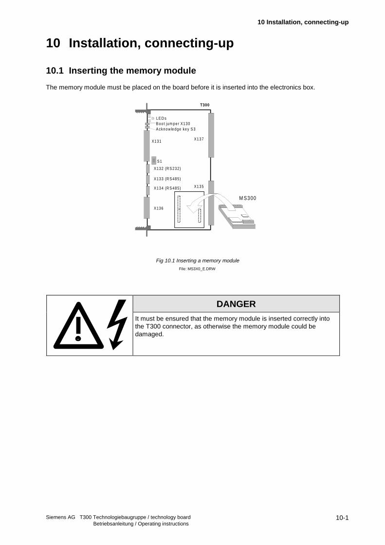
10.1 Inserting the memory module
The memory module must be placed on the board before it is inserted into the electronics box.
Fig 10.1 Inserting a memory module
File: MS3X0_E.DRW
DANGER
It must be ensured that the memory module is inserted correctly intothe T300 connector, as otherwise the memory module could bedamaged.
M S300
X137
X135
X131
X136
X132 (R S 232)
X134 (R S 485)
B oo t jum per X130LE D s
A cknow ledge key S 3
X133 (R S 485)
S 1
T300

10 Installation, connecting-up
Siemens AG T300 Technologiebaugruppe / technology boardBetriebsanleitung / Operating instructions
10-2
10.2 Installing the board
Slots in the electronics box Boards
Left Slot 1 (CU) CU
Center Slot 3 (options) CB1 / CBx with ADB / SCB1 / SCB2 / (TSY, not for T300)
Right Slots 2 (options) CB1 / CBx with ADB / SCB1 / SCB2 / TSY / T300
NOTE
Only one of each option board type may inserted in the electronics box.
TB (technology boards, e.g. T300) must always be inserted at slot 2.
When a TB board is used, a TSY board may not be inserted.
If only one option board is used it must always be inserted at slot 2.
Option board Order Nos. and their descriptions are found in the Instruction Manual of the Master Driveconverter.
Examples of possible arrangements: Slot 1 Slot 3 Slot 2
CU --- SCB
CU --- CBx
CU --- T300
CU SCB T300
CU CBx T300
CU TSY SCB

10 Installation, connecting-up
Siemens AG T300 Technologiebaugruppe / technology board Betriebsanleitung / Operating instructions
10-3
Please adhere to the following rules for mounting the T300 and other supplementary boards into theelectronics box.
Please note: Only the following combinations and mounting positions are allowed.
− The T300 must be mounted in mounting location 2 (rightmost mounting location)
− Only one fieldbus communication board can be used. It must be mounted in mounting location 3(middle location). Communication boards which are designed as Mini-Slot-Boards (e.g. CBP, CBC)must additionally be mounted in Slot "G" of an ADB Adaption Bord before inserted in mounting location3. The T300 can not communicate with a communication board mounted on the CU ( in slot A or C ).
− The Communication Board communicates directly with the T300 board.
− An optinal SLB SIMOLINK Interface Board must be mounted in a slot on the CUVC or CUMC baseelectronics board, most preferably in Slot A..
The combination T300 and SLB SIMOLINK Interface mounted in location 3 is not possible!
CAUTIONA T300 board with Hardware release ≥ B, or newer, is needed for use with an SLB SIMOLINKinterface board. The correct hardware release code can be detected on the component side of theT300 in the neighbourhood of the lower backplane connector.
A
C
F
G
Mounting Positions
1 3 2
- C U VC- C U M C- C U 2, C U 3- 6R A70
- C Bx m ounted on AD B A dap- tion Board- C B1 - SC B 1- SC B 2
- T 300
D ata F low
D on't use s lo t F
E lec tron icsB ox

10 Installation, connecting-up
Siemens AG T300 Technologiebaugruppe / technology boardBetriebsanleitung / Operating instructions
10-4
Before installing option boards in the electronicsbox, the LBA (local Bus Adapter) has to beinserted.
Install the LBA bus expansion:
♦ Remove the CU (lefthand slot in the electronicsbox) using the handles after first removing theconnecting cable to the PMU and both retainingscrews
♦ Insert the LBA bus expansion in the electronicsbox (position, refer to the diagram) so that itsnaps into place
♦ Re-insert the CU into the lefthand slot, screwthe retaining screws on the handles tight, andinsert the connecting cable to the PMU
Insert the option board in the righthand or centerslot of the electronics box and screw into place.Only one of each option board type may beinserted in the electronics box. If only one optionboard is inserted, then it must always be at slot 2 (right).
Installing a new board
♦ Undo the two fixing screws on thehandles above and below theboard.
♦ Pull the board out of theelectronics box using the handles
♦ Insert the new board. The boardmust be pressed tightly onto theplug connector.
♦ Screw the board tight at the fixingpoints in the front section of theboard using the two screwsattached.
Fig. 10.2.a Installing the local bus adapter
Slot 3 (Option)
Slot 1 (CU)
Slot 2 (Option)
Fig. 10.2.b: Elektronics box, with CU (Slot 1)
and Options (Slot 2 (left) and 3 (right))

10 Installation, connecting-up
Siemens AG T300 Technologiebaugruppe / technology board Betriebsanleitung / Operating instructions
10-5
10.3 Connections
10.3.1 T300 and SE300 terminal module connections
Fig. 10.3.a: T300 connections
File: T3AUFB_E.DRW
P aram eteriza tion by theservice prog ram
X45
6X
451
SE300
LB
A
X137
X135
X131
X 136
X 132 (R S 232)
X 134 (R S 485)
B oot jum per X 130LE D s
A cknow ledge button S 3
X 133 (R S 485)
S1
T300
M em orysub-
m odue
Pee
r-to
-pee
r co
nnec
tion
Se rv ice
S C 60
S C 58
501
549601
640
Analog I/O pulse encoder
B inary I/O s
X5
X6
X131
X132
X134
LEDs
X133
S1
T300
S eria l in terface 1
S eria l in terface 2

10 Installation, connecting-up
Siemens AG T300 Technologiebaugruppe / technology boardBetriebsanleitung / Operating instructions
10-6
File: T300_E.DRW
Note: For the first SE58 which were supplied (Order No.: 6DD3460-0AB0, Item No.. 465460.9001.00)terminals 630...640 are designated as 620...630!
52 3
51 9
52 1
50 9
Z eropu lse
5
4
5 38 5 37 5 35 533 53 1 5 40 53 9 54 8 54 7 545 543 541 5 49
6 39
X134
X132
R S 232
1506
M icroprocessorCPU:
80C18620MHz
RS485, 4-wire
637
638
640
Serial interface 2(peer-to-peer)
4 analog outputs±10 V / 1 0m A
8 binary outputs24V D C / m ax. 100m A .40 m A base load for theexterna l P 24 supp ly, w h ich can a lso com e fromthe basic drive converter
S lo t fo r them em orym odu le , e .g .M S 300
Com m unicationsboard, e.g.CB1, CBP on ADB,SCB1 or SCB2
Dual-Po rt-RAM
M ASTER DRIVESbasic drive conv.
CU1, CU2, CU3CUM C, CUVC(CUx board)
D ual-Port-R AM
1 /2 LB A1 /2 LB A
X6
X13 5 X13 7
630
611
612
613
614
615
616
617
618
+
+ 24V
610
601
602
603
604
605
606
607
608
+
+ 24V
8 b inary inputs24VD C(inp u t res is tan ce4KO hm typ .)
X6
512
516
515
514
513
505
AD
+-
AD
+-
AD
+-
511
7 analog inputsd iffe ren tia l inpu ts11 b its + s ign±10V / 10k O hm
502
504
503
AD
+-
AD
+-
501
±10V
±10V
±10V
508
507
AD
+-
AD
+-
±10V
±10V
±10V
±10V
X5
8 b inary inputs24V DC(inp u t res is tan ce :4KO hm typ .)
Pulse encoder sensing 1 Pulse encoder sensing 2
+1 5V +1 5V
9 0° 0 °
X 5 .
+ 24 V
90 °Z eropu lse 0°
R oug hp u lse
Serial interface 1start-up program
R S485, 2 w ire
6
7
8
9
10
T/R x+
T/R x-
X133
TTL
TxD
R xD
3
2
R x+
Tx-
Rx-
Tx+ 13
14
11
12
15
AD
510
X5
AD
520
AD
522
AD
524
2 pulse encoder inputsH TL leve l, m ax.400kH z input frequencinput current: 8m A per channel
E ither RS232 orRS 485 interfacecan be used
63 1
63 2
63 3
634
635
636
+24V
Term ina l series X 5, X 6: C onnect a t te rm ina l b lock S E 300Term ina l series X 132, X 133, X 134: C onnect a t T300
C onnecting d iagram , T300,S E300
11 bits + s ign
+15V / 100m A
+ 24 VF ine p u lse
10 Installation, connecting-up
Siemens AG T300 Technologiebaugruppe / technology board Betriebsanleitung / Operating instructions
10-7
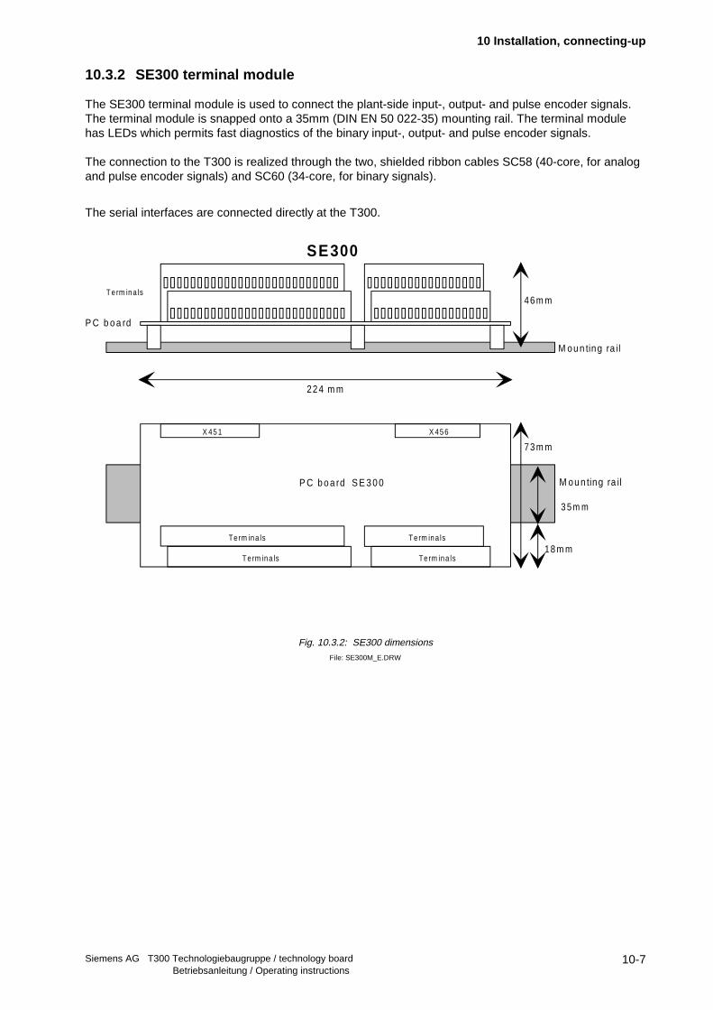
10.3.2 SE300 terminal module
The SE300 terminal module is used to connect the plant-side input-, output- and pulse encoder signals.The terminal module is snapped onto a 35mm (DIN EN 50 022-35) mounting rail. The terminal modulehas LEDs which permits fast diagnostics of the binary input-, output- and pulse encoder signals.
The connection to the T300 is realized through the two, shielded ribbon cables SC58 (40-core, for analogand pulse encoder signals) and SC60 (34-core, for binary signals).
The serial interfaces are connected directly at the T300.
Fig. 10.3.2: SE300 dimensions
File: SE300M_E.DRW
M ou n ting ra il
SE300
73 m m
P C b o a rd
3 5 m m
X 45 1 X 45 6
T erm ina ls
P C b o a rd S E 3 0 0
M ou n ting ra il
22 4 m m
18 m m
46 m m
Term ina ls
T e rm ina ls
T e rm ina ls
Te rm ina ls

10 Installation, connecting-up
Siemens AG T300 Technologiebaugruppe / technology boardBetriebsanleitung / Operating instructions
10-8
10.3.3 Connecting-up pulse encoders (digital tachometers) at SE300
10.3.3.1 Connection possibilities
The T300 provides a 15 V voltage via the SE300 for one pulse encoder, so that either pulse encoder 1 orpulse encoder 2 can be supplied without having to use an external power supply.
24 V pulse encoders can also be used, whereby it should be observed, that the pulse encoder could beoverloaded if long cable are used in conjunction with high frequencies (e.g. 150m, 40kHz), which couldresult in speed actual value sensing errors.
The speed actual value can also be lost, if the cable capacitance prevents the input voltage decreasing toless than 5 V for a pulse encoder LOW signal.
Only unipolar encoder signals can be evaluated.
The encoder reference potentials must be connected with the speed input reference points of the SE300:Terminal 531, 533, 535 or 539 for encoder 1Terminal 541, 543, 545 or 549 for encoder 2
When using an external power unit, its ground must also be connected to SE300 (e.g. terminal 539).
An external power supply unit can also supply both pulse encoders, whereby in this case, terminals 539and 549 must be connected to the power supply ground.
The zero pulses are only required for certain applications (e.g. synchronizing drives).
Using a rough signal, a window can be defined, in which a zero pulse can be identified and evaluated.Such a rough signal can be generated, for example, from a contact switch or proximity switch. The zeropulse is evaluated when the rough signal = 1.
Fig. 10.3.3.1.a: Connecting pulse encoders with zero pulse
File: SEIMP_E.DRW
P ulse encode r 1
P15M
Tra
ck B
1
Tra
ck A
1
P u lse encoder 2
Tra
ck B
2
Tra
ck A
2
531
532
533
534
535
536
539
540
541
542
543
544
545
546
549
M
P 15 , from the exte rna lpow er supp ly sec tion
SE300
X 5
Zer
o pu
lse
1
Zer
o pu
lse
2

10 Installation, connecting-up
Siemens AG T300 Technologiebaugruppe / technology board Betriebsanleitung / Operating instructions
10-9
Using a single-track pulse encoder :
- the pulse encoder pulse track is connected at track A1 or A2 (terminals 531 or 541)- the track inputs B1 or B2 of the pulse encoder sensing (terminals 533 or 543) are connected toground.
As the SIMOVERT VC includes closed-loop speed control, then typically, an encoder („encoder input 1“) isdirectly connected to control board CU2 (terminals X103.35 to X103.40 ) or CUVC (terminals X103.35 toX103.40) . The pulses, fed to CU2, are supplied to the T300 via the LBA.This does not load the pulse encoder connected at the CU.
For servo converters SIMOVERT SC (CU3 control board) or MASTERDRIVE Motion Control (CUMCcontrol board), the resolver signals are transformed into pulse encoder signals (tracks A1, B1, N) andare also fed to T300 via the LBA.
For SIMOREG DC_MASTER (6RA70) typically, an encoder is directly connected to control board (terminals X173.26 to X173.33 ). The pulses, fed to CU, are supplied to the T300 via the LBA.This does not load the pulse encoder connected at the CU.
In this case, these pulses are not just available on the control board for speed sensing, but also on theT300 via the LBA.
Fig. 2.3.3.1.b: Connecting the pulse encoder
File: IMPULS_E.DRW
LB A
SC 58
A 1B 1N 1
A 1B 1N 1
A 2B 2N 2
T300
SE300
CU2, CUVC 6RA70
CU3, CUMC
R eso lve r s igna lstrans fo rm erR eso lve r
C hangeover can be configured
from encoder input1
from encoder inpu t 1
from encoder inpu t 2
Speedsensing 1
S peedsens ing 2

10 Installation, connecting-up
Siemens AG T300 Technologiebaugruppe / technology boardBetriebsanleitung / Operating instructions
10-10
10.3.3.2 Information regarding the pulse encoder cable
Capacitance per unit length of the pulse encoder cable:
Core - shield: approx. 265 pF/mCore - core: approx. 120 pF/m
1. For long cables, it must be ensured, that there is still enough voltage at the pulse encoder to ensurecorrect operation.
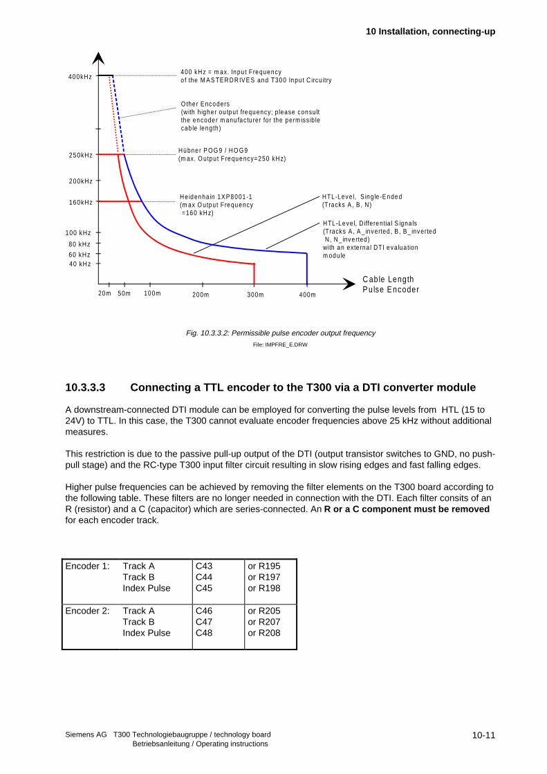
2. Max. pulse encoder output frequency:
Max. Pulse Encoder Frequency as a Function of the Cable Length with the HTL Encoder Inputs ofMASTERDRIVES and T300.
Below you can find a pulse frequency vs. cable length characteristic curve. The following assumptionshave been made for this curve:
1. Encoder types: Heidenhain 1XP8001-1 and Hübner ROD9 / HOG9
2. Stabilized +15 VDC encoder power supply . Both, the CU board and the T300 board provide outputterminals each supplying one encoder with the appropriate power-supply voltage. (i.e. two encoderscan be supplied in total).
3. With pulse frequencies above 50 kHz or cable lengths above 50 m, two parallel-connected conductorshave to be used for the 15VDC and GND encoder supply leads in order to make the voltage drops aslow as posible.Four parallel-connected conductors have to be used with cable lengths above 100m. As an alternative,you can use 15VDC and GND conductors with a minimum cross-section of 1 mm2 each.
4. Appropriate encoder cables:- Siemens 6SX7002... according to Motor-Catalog DA65.3- other shielded twisted -pair cables with the following features:
- min. cross-section of the conductors: 0,25 mm2
- max. capacitance per unit length: 120 pF/m
5 For cable lengths above 150m, the use of an encoder with additional complementary HTL signals ishighly recommended (differential pulse signals A/A_inverted, B/B_inverted, N/N_inverted).A Siemens DTI "Digital-Tacho Interface" module has to be employed in this case, refer to MASTER-DRIVES-Catalog DA65.10.The 1XP8001-1 encoder type is equipped with the complementary outputs as a standard. The ROD9 /HOG9 types can be ordered, as a special version, from Hübner with complementary outputs. Use theHübner-Order No suffix " ...I" for ordering.
10 Installation, connecting-up
Siemens AG T300 Technologiebaugruppe / technology board Betriebsanleitung / Operating instructions
10-11
Fig. 10.3.3.2: Permissible pulse encoder output frequency
File: IMPFRE_E.DRW
10.3.3.3 Connecting a TTL encoder to the T300 via a DTI converter module
A downstream-connected DTI module can be employed for converting the pulse levels from HTL (15 to24V) to TTL. In this case, the T300 cannot evaluate encoder frequencies above 25 kHz without additionalmeasures.
This restriction is due to the passive pull-up output of the DTI (output transistor switches to GND, no push-pull stage) and the RC-type T300 input filter circuit resulting in slow rising edges and fast falling edges.
Higher pulse frequencies can be achieved by removing the filter elements on the T300 board according tothe following table. These filters are no longer needed in connection with the DTI. Each filter consits of anR (resistor) and a C (capacitor) which are series-connected. An R or a C component must be removedfor each encoder track.
Encoder 1: Track ATrack BIndex Pulse
C43C44C45
or R195or R197or R198
Encoder 2: Track ATrack BIndex Pulse
C46C47C48
or R205or R207or R208
C able LengthP u lse E ncoder20m 50m 100m 300m
40 kHz
80 kHz
200kHz
400kHz
100 kHz
250kHz
160kHz
H übne r P O G 9 / H O G 9(m ax. O utput Frequency=250 kH z)
H e idenha in 1X P 8001 -1(m ax O utput Frequency =160 kH z)
200m 400m
60 kHz
400 kH z = m ax. Inpu t Frequencyo f the M A S TE R D R IV E S and T300 Inpu t C ircu itry
O the r E ncoders(with h igher ou tput frequency; p lease consu ltthe encode r m anu fac tu rer fo r the perm iss ib lecab le length)
H TL-Leve l, S ing le -E nded(Tracks A , B , N)
H TL-Leve l, D iffe rentia l S igna ls(Tracks A , A _ inverted , B , B _ inverted N, N _ inve rted)with an exte rna l D TI eva lua tionm odule

10 Installation, connecting-up
Siemens AG T300 Technologiebaugruppe / technology boardBetriebsanleitung / Operating instructions
10-12
10.3.3.4 Rough signal processing
The T300 allows the zero pulse only to be evaluated if the „rough signal“ is present. If such a AND logicoperation is to be made (in the sense of a filter function), then the speed sensing (function function blockNAV015) must be appropriately parameterized.
Fig. 10.3.3.4.a: Rough signal speed sensing 1 and 2
File: DREHZG_E.DRW
Fig. 10.3.3.4.b: Zero pulse evaluation with rough signal
File: IMP_E.DRW
R oughs igna l 2
C ontac t-/p roxim itysw itch e tc .
X 5
R oughs igna l 1
531
532
533
534
535
536
539
540
541
542
543
544
545
546
549
SE300
537 547
548538
P 24
M
T rack A
T rack B
Zero pu lse
T1 T2
T3
T 1, T2 and T3, > 1µ sec
R ough s ignal
Zero pu lse evaluation

10 Installation, connecting-up
Siemens AG T300 Technologiebaugruppe / technology board Betriebsanleitung / Operating instructions
10-13
10.3.4 Connecting-up the analog inputs
Fig. 10.3.4: Connecting the analog inputs and analog outputs
File: ANALIN_E.DRW
♦ The analog inputs are differential inputs , in order to suppress common-mode noise anddisturbances. The „reference potential“ (e.g. terminal 502 for input 1) must therefore also beconnected!Further, it should be noted that the inputs are non-floating via the A/D converter!
♦ For unipolar signals, the inverting inputs must be connected at the analog signal reference points.
♦ Noisy signals must be smoothed using a low-pass filter, which is externally mounted. Therecommended circuit, illustrated in fig. above refers to analog input sampling times of ≥ 8ms.
10V
1 kO hm Analog input 1
X131+-
+-
10 µ F
~ 1 0 kO hm
50
1
51
0
507
50
9
50
2
51
15
03
SE300
X451
X5
Input 1
Input 2
Ana log output 1
52
0 SC58
T300
Output 1
50
4

10 Installation, connecting-up
Siemens AG T300 Technologiebaugruppe / technology boardBetriebsanleitung / Operating instructions
10-14
10.3.5 Connecting-up the binary inputs
Binary signals have a 24 V DC signal level referred to M24 (SE300 terminals 610, 630 or 640).
Low signal level (logical zero) is identified for- an open-circuit input- signals below +6V.
A high signal level is defined for voltages between 13 V and 33 V.
The input current at 24 V is typically approx. 5 mA and the delay time, approx. 1 ms.
Fig. 10.3.5.a: Circuit diagram of a binary input
File: BINEIN_E.DRW
Fig. 10.3.5.b: Connecting-up the binary inputs and outputs
File: BINARI_E.DRW
S E 300 T300
leve l trans form er
M 24 M 24
24V D Cpow er supply
SE 300
P 24
M
M
P 24
outpu to r
S IM A TIC -b inary ou tpu t
S C 60
X 136T 300
602 610
631
632
639
640
S IM A T ICb ina ry input
B inary input B ina ry outpu t
X 456
601 603
X 456

10 Installation, connecting-up
Siemens AG T300 Technologiebaugruppe / technology board Betriebsanleitung / Operating instructions
10-15
10.3.6 Connecting-up the binary outputs
The binary outputs are also 24V DC signals, which are referred to M24 (terminal 610, 630 or 640 of theSE300). They are supplied from the P24 terminals (609, 619 or 639).
Each of the 8 outputs (terminals 631 to 638) can drive 0.2 mA to 100 mA, which is sufficient to controlsmall signaling lamps or interface relays. A free-wheeling diode is provided on the T300, however, forinductive loads, it is recommended that a free-wheeling diode is directly connected at the load.
The outputs have electronic short-circuit protection to ground and P24.
The total of all outputs may not exceed 400 mA; the operating voltage range is +20 V to +30 V.
The switching delay is approx. 300 µs.
Fig. 10.3.6: Circuit diagram of a binary output
File: BINAUS_E.DRW
P24 power supply voltage:
Binary inputs:
♦ The power supply voltage can either be taken from the drive converter (connector X101,terminals 13 and 23) or from an external power supply source.
Binary outputs:
♦ The power supply voltage can be taken from the converter or an external power supply.It should be noted, that a maximum of 150 mA can only be taken from the converter P24 supply(also refer to Section 10.4)
S E300T 300
24V D Cpow er supp ly
Driver
P24
M 24
P24
M 24
Load

10 Installation, connecting-up
Siemens AG T300 Technologiebaugruppe / technology boardBetriebsanleitung / Operating instructions
10-16
10.3.7 Connecting-up the serial interfaces
10.3.7.1 Serial connections, X132
Fig. 10.3.7.1: T300 serial connections
File: X132_E.DRW
T xD
R xD 3
7
X 132
G N D
22
R xD1
3
45
TxD
PC-AT(seria l interface)
TxD
R xD 2
5
X 132
G N D
23
R xD1
3
45
TxD
PG7X0 program ming unit(serial interface)
T300
25-p in sub Dp lug connec to r
T300
9-p in sub Dplug connec tor

10 Installation, connecting-up
Siemens AG T300 Technologiebaugruppe / technology board Betriebsanleitung / Operating instructions
10-17
10.3.7.2 Peer-to-peer connection, X134
The peer-to-peer connection is used to cascade the setpoint between the drives .
♦ A transmitter only supplies one receiver:⇒ For the receiver, the terminating resistors must be switched-in.
♦ A transmitter can supply up to 31 receivers:⇒ All receivers must be connected as for a serial bus due the cable characteristic
impedance. This means, that an incoming and an outgoing bus cable connector mustbe connected at each receiver.The terminating resistors must be effective for the last receiver in the chain. It is notpermissible to connect-up the receivers in a star configuration!
Refer to Section 10.6 for further details regarding the terminating resistors.
Every cable section must be shielded!
Fig.10.3.7.2: Peer-to-peer connection
File: PEER_E.DRW
x: For this T300, the bus terminating resistors must be switched-in, i.e. at bus terminating switch S1, coding switches S1.3 and S1.4 must be set to ON!
point-to-po in t
cascade
11 12 13 14 15
-X 134
Rx+ R x- Tx+ T x- M
11 12 13 14 15
-X134
Rx+ R x- T x+ Tx- M11 1 2 13 14 15
-X 134
Rx+ R x- Tx+ T x- M11 12 13 14 15
-X 134
Rx+ R x- Tx+ T x- M11 12 13 14 15
-X 134
Rx+ R x- Tx+ T x- M
11 1 2 13 14 15
-X 134
Rx+ R x- Tx+ T x- M11 12 13 14 15
-X 134
Rx+ R x- Tx+ T x- M11 12 13 14 15
-X 134
Rx+ R x- Tx+ T x- M
X X X
X
M aste r drive

10 Installation, connecting-up
Siemens AG T300 Technologiebaugruppe / technology boardBetriebsanleitung / Operating instructions
10-18
11 Technical data
Siemens AG T300 Technologiebaugruppe / technology board Betriebsanleitung / Operating instructions
11-1
11 Technical data
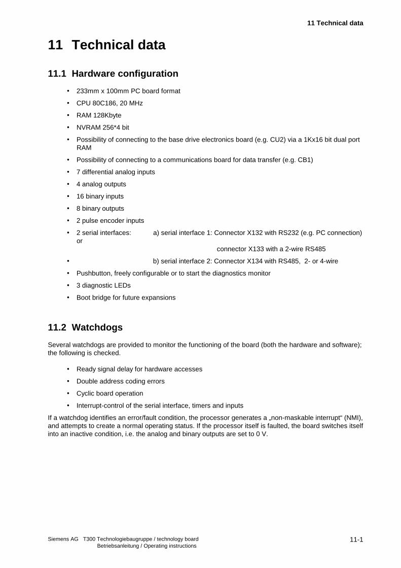
11.1 Hardware configuration
• 233mm x 100mm PC board format
• CPU 80C186, 20 MHz
• RAM 128Kbyte
• NVRAM 256*4 bit
• Possibility of connecting to the base drive electronics board (e.g. CU2) via a 1Kx16 bit dual portRAM
• Possibility of connecting to a communications board for data transfer (e.g. CB1)
• 7 differential analog inputs
• 4 analog outputs
• 16 binary inputs
• 8 binary outputs
• 2 pulse encoder inputs
• 2 serial interfaces: a) serial interface 1: Connector X132 with RS232 (e.g. PC connection)or
connector X133 with a 2-wire RS485
• b) serial interface 2: Connector X134 with RS485, 2- or 4-wire
• Pushbutton, freely configurable or to start the diagnostics monitor
• 3 diagnostic LEDs
• Boot bridge for future expansions
11.2 Watchdogs
Several watchdogs are provided to monitor the functioning of the board (both the hardware and software);the following is checked.
• Ready signal delay for hardware accesses
• Double address coding errors
• Cyclic board operation
• Interrupt-control of the serial interface, timers and inputs
If a watchdog identifies an error/fault condition, the processor generates a „non-maskable interrupt“ (NMI),and attempts to create a normal operating status. If the processor itself is faulted, the board switches itselfinto an inactive condition, i.e. the analog and binary outputs are set to 0 V.
11 Technical data
Siemens AG T300 Technologiebaugruppe / technology boardBetriebsanleitung / Operating instructions
11-2
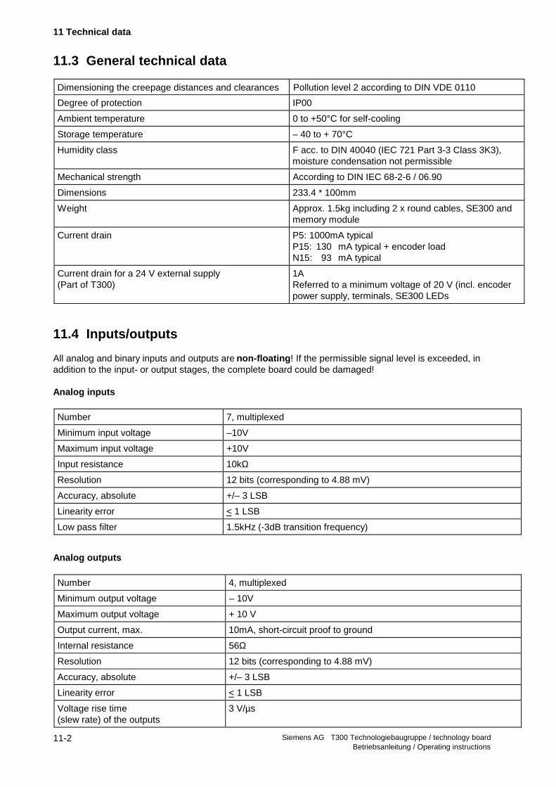
11.3 General technical data
Dimensioning the creepage distances and clearances Pollution level 2 according to DIN VDE 0110
Degree of protection IP00
Ambient temperature 0 to +50°C for self-cooling
Storage temperature – 40 to + 70°C
Humidity class F acc. to DIN 40040 (IEC 721 Part 3-3 Class 3K3),moisture condensation not permissible
Mechanical strength According to DIN IEC 68-2-6 / 06.90
Dimensions 233.4 * 100mm
Weight Approx. 1.5kg including 2 x round cables, SE300 andmemory module
Current drain P5: 1000mA typical P15: 130 mA typical + encoder load N15: 93 mA typical
Current drain for a 24 V external supply(Part of T300)
1A Referred to a minimum voltage of 20 V (incl. encoderpower supply, terminals, SE300 LEDs
11.4 Inputs/outputs
All analog and binary inputs and outputs are non-floating ! If the permissible signal level is exceeded, inaddition to the input- or output stages, the complete board could be damaged!
Analog inputs
Number 7, multiplexed
Minimum input voltage –10V
Maximum input voltage +10V
Input resistance 10kΩ
Resolution 12 bits (corresponding to 4.88 mV)
Accuracy, absolute +/– 3 LSB
Linearity error < 1 LSB
Low pass filter 1.5kHz (-3dB transition frequency)
Analog outputs
Number 4, multiplexed
Minimum output voltage – 10V
Maximum output voltage + 10 V
Output current, max. 10mA, short-circuit proof to ground
Internal resistance 56Ω
Resolution 12 bits (corresponding to 4.88 mV)
Accuracy, absolute +/– 3 LSB
Linearity error < 1 LSB
Voltage rise time(slew rate) of the outputs
3 V/µs

11 Technical data
Siemens AG T300 Technologiebaugruppe / technology board Betriebsanleitung / Operating instructions
11-3
Binary inputs
Number 16, interrupt-capable
Input voltage +24V nominal value
Input voltage for 0 signal –1V to +6V or open binary inputs
Input voltage for 1 signal +13V to +33V
Input current for a 1 signal 8mA typical
Input smoothing < 700µs
Binary outputs
Number 8,
Power supply voltage Must be fed-in externally
Nominal value 24V DC
Ripple 3.6V peak-to-peak (smoothing not required)
Permissible range + 15 to + 40V, including ripple
Short-time loading + 40V < 0.5s
Basic loading (all outputs open) < 40mA
Output current for a 1 signal
Nominal value 100mA (92mA at SE300 terminal)
Permissible range 0.2mA to 100mA
Only loaded by the LED 8mA
Short-circuit protection Continually short-circuit proof with respect to ground and P24
Total loading Summed current of all outputs < 400mA
Signal level for 0 signal Max. 2 V for load < 5kΩ
For a 1 signal External supply voltage –2.5V
Switching delay Max. 300µsec.
Pulse encoder connection (speed actual value sensing):
Number of pulse encoders which may be connected 2
Max. pulse frequency 400kHz
Min. duration for the signals A, B, N: > 1µsec
Nominal displacement between tracks A and B > 1µsec at every speed
Pulse level 0 – 30V
Signal level with input hysteresis:
1 signal > 8V
0 signal (optimized for pulse encoders with 15 V power supply voltage) < 5V
Input currents 8mA typical
Rough signal Values as for binary inputs
Voltage at the external terminals (SE300) for the pulse encoder supply:
Output voltage Nominal value: 15V, typically 14V
Output current, max. 0.1A, electronically limited to 0.15A under short-circuit conditions

11 Technical data
Siemens AG T300 Technologiebaugruppe / technology boardBetriebsanleitung / Operating instructions
11-4
11.5 Serial interfaces
The T300 has 2 serial interfaces:
1. Serial interface 1 terminals X132 or X133 on T300
Serial interface 1 is a 2-wire cable according to RS485 (X133) and RS232 (X132).
In the STRUC master program, this interface corresponds to connector X01.
NOTE
Serial interface 1 can either be used as RS485 or as RS232; this means, it is not permissible tosimultaneously use the physical interfaces at terminal series X132 and X133!
2. Serial interface 2, terminals X134 on T300
Serial interface 2 is a 2- or 4-wire cable according to RS485 (X134). Changeover to 2- or 4-wire cable isrealized automatically corresponding to the protocol set at the interface.
In the STRUC master program, this interface corresponds to connector X02.

11 Technical data
Siemens AG T300 Technologiebaugruppe / technology board Betriebsanleitung / Operating instructions
11-5
The subsequent two diagrams show a schematic of serial interfaces 1 and 2, in conjunction with the busterminating switch S1.
Fig. 11.5.a: Connecting serial interface 1 (RS485/RS232)
File: SST1_E.DRW
Fig. 11.5.b: Connecting serial interface 2 (RS485)
File: SST2_E.DRW
P 5P 5
M M
100K
100K
390
390
470p
470p
T T L
R S 232
470p
470p
M 56u
S S T 1_T xD
S S T 1_R xD
D IR
(D irec tion changeove r)
TTL / R S 485
P E
1
2
3
X133
N 12
10k
T xD
R xD
10n
X132
6
7
8
9
10
150
4
5
M56u
S1.2
S1.1
10n
470p
470p
P 5
M
390
390
470p
470p
S ST2_TxD
S S T 2_R xD
T T L / R S 485
D IRP E
11
12
X134
D IR
M
P 5
M
390
390
M
10n
56u
14
15
13
T T L / R S 485
150
150
M
100K
P 5
100K
0
S1.4
S1.3
(D irec tion changeover)

11 Technical data
Siemens AG T300 Technologiebaugruppe / technology boardBetriebsanleitung / Operating instructions
11-6
11.6 Bus terminating switch S1
The bus terminations are switched-in when switch S1 is in the ON position (coding switches 1-4).The bus terminating resistance is approx. 120 Ohm.
Fig. 11.6: Bus terminating switch S1
File: BUSABS_E.DRW
NOTE
Coding switches 1 and 2 or 3 and 4 must always be in the same setting so that the bus terminations are eitherswitched-in or -out.
11.7 Pushbutton S3
A) Using the pushbutton, the SIMADYN D diagnostics monitor (9.6 kbaud, no parity bit) can be startedwhen the voltage runs-up. It is only effective at interface 1 (connector X132/X133), which is then no longeravailable for other applications once the monitor has started!Generally, the user does not use this monitor.
a) If a fatal T300 error/fault is identified during operation, which prevents the T300 operatingcorrectly, then the diagnostics monitor can be started by actuating the pushbutton.
b) Independent of a possibly occuring error/fault, the monitor can be started at voltage run-up. Thepushbutton must be depressed until the system goes into a READY status (°008 or °009)!
B) The pushbutton can also be implemented (configured) with a switch function within the software. Thediagnostic monitor can still be started (as described under A).
1 2 3 4
O N
B us te rm ina tion sw itched-in
B us te rm ina tion sw itched-out
X 134X 133

11 Technical data
Siemens AG T300 Technologiebaugruppe / technology board Betriebsanleitung / Operating instructions
11-7
11.8 Diagnostic LEDs
Flashing of the LED indicates that the unit is in a perfect operating status. The associated LED is either litor dark if a fault condition is present.
H1 Red LED Dependent on the particular configuring:The flashing frequency is the sampling time of the function package@SIMD (TY-connector of T300 Board mask)In case of error it is 4 times lower!
H2 Green LED Data transfer to the communications board O.K.;The flashing frequency is the sampling time of the DCCZ functionfunction block
H3 Yellow LED Data transfer to the basic drive converter O.K.;The flashing frequency is the sampling time of the DCCZ functionfunction block

11 Technical data
Siemens AG T300 Technologiebaugruppe / technology boardBetriebsanleitung / Operating instructions
11-8
11.9 Connector assignments
Analog inputs/outputs and pulse encoder
Connectionexample
SE300X5
Function T300X131
ADconnector
(FB)
Explanation
501 Input 1 + 1 X5 A
502 Input 1 - 2
503 Input 2 + 3 X5 B
504 Input 2 - 4 Analog inputs 1 - 4
505 Input 3 + 5 X5 C
506 Input 3 - 6
507 Input 4 + 7 X5 D
508 Input 4 - 8
509 Analog output 1 9 X5 H Analog out put 1
510 Ground analog (=520) 10
511 Input 5+ 11 X5 E
512 Input 5- 12
513 Input 6+ 13 X5 F Analog inputs 5 - 7
514 Input 6- 14
515 Input 7+ 15 X5 G
516 Input 7- 16
519 Analog output 2 17 X5 J
520 Ground analog (=510) 10521 Analog output 3 19 X5 K Analog out puts 2-4
522 Ground analog (=524) 18523 Analog output 4 20 X5 L
524 Ground analog (=522) 18
531 Track 1A+ 21
532 Ground track 1A 22
533 Track 1B+ 23
534 Ground track 1B 24
535 Zero pulse 1+ 25 X5 M Speed sensing 1
536 Ground zero pulse 1 26
537 Rough pulse 1 27
538,539
Ground, encoder supply 1,Ground rough pulse 1
28, 29
540 15V encoder supply 30,39
541 Track 2A+ 31
542 Ground track 2A 32
543 Track 2B+ 33
544 Ground track 2B 34
545 Zero pulse 2+ 35 X5 N Speed sensing 2
546 Ground zero pulse 2 36
547 Rough pulse 2 37
548,549
Ground, encoder supply. 2,Ground rough pulse 2
38, 40
1k 10µF
10k10V
11 Technical data
Siemens AG T300 Technologiebaugruppe / technology board Betriebsanleitung / Operating instructions
11-9
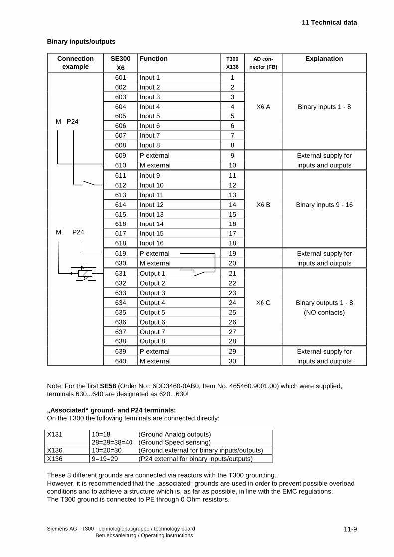
Binary inputs/outputs
Connectionexample
SE300X6
Function T300
X136
AD con-
nector (FB)Explanation
601 Input 1 1
602 Input 2 2
603 Input 3 3
604 Input 4 4 X6 A Binary inputs 1 - 8
605 Input 5 5
606 Input 6 6
607 Input 7 7
608 Input 8 8
609 P external 9 External supply for
610 M external 10 inputs and outputs
611 Input 9 11
612 Input 10 12
613 Input 11 13
614 Input 12 14 X6 B Binary inputs 9 - 16
615 Input 13 15
616 Input 14 16
617 Input 15 17
618 Input 16 18
619 P external 19 External supply for
630 M external 20 inputs and outputs
631 Output 1 21
632 Output 2 22
633 Output 3 23
634 Output 4 24 X6 C Binary outputs 1 - 8
635 Output 5 25 (NO contacts)
636 Output 6 26
637 Output 7 27
638 Output 8 28
639 P external 29 External supply for
640 M external 30 inputs and outputs
Note: For the first SE58 (Order No.: 6DD3460-0AB0, Item No. 465460.9001.00) which were supplied,terminals 630...640 are designated as 620...630!
„Associated“ ground- and P24 terminals:On the T300 the following terminals are connected directly:
X131 10=18 (Ground Analog outputs)28=29=38=40 (Ground Speed sensing)
X136 10=20=30 (Ground external for binary inputs/outputs)X136 9=19=29 (P24 external for binary inputs/outputs)
These 3 different grounds are connected via reactors with the T300 grounding.However, it is recommended that the „associated“ grounds are used in order to prevent possible overloadconditions and to achieve a structure which is, as far as possible, in line with the EMC regulations.The T300 ground is connected to PE through 0 Ohm resistors.
M P24
M P24

11 Technical data
Siemens AG T300 Technologiebaugruppe / technology boardBetriebsanleitung / Operating instructions
11-10
Serial interfaces
Connector X132 (serial interface 1)
TerminalNo.
RS232
1 RxD
2 TxD
3 Ground
4 Ground
5 Ground
Connector X133 (serial interface 1)
TerminalNo.
RS4852-wire operation
6 + RxD / +TxD
7 - RxD / - TxD
8 + RxD / +TxD
9 - RxD / - TxD
10 Ground
Connector X134 (serial interface 2)
TerminalNo.
RS485 for2-wire operation
RS485 for4-wire operation
11 +RxD / +TxD +RxD
12 - RxD / -TxD - RxD
13 No function (+TxD) +TxD
14 No function (-TxD) -TxD
15 Ground Ground

12 Application software
Siemens AG T300 Technologiebaugruppe / technology board Betriebsanleitung / Operating instructions
12-1
12 Application software
The T300 control software can either be generated, user-specific using STRUC (refer to the next section),or pre-configured standard software packages may purchased from Siemens.
12.1 Standard software packages
Four different standard software packages are available in the form of pre-programmed memory modules:
♦ MS320 Axial winder
♦ MS340 Angular synchronous control
♦ MS360 Multi-motor drive
♦ MS 380 Positioning
Fig. 12.1: Standard software packages
File: STANDPR_E.DRW
RELEASE Standard software packagesThe T300 standard software packages MS320, MS340, MS360, MS380 are released for operation inthe MASTER DRIVES basic units (CU2, CU3, CUVC, CUMC).
The T300 standard software packages MS320, MS340, MS360, MS380 are not released for operationin the SIMOREG DC_MASTER 6RA70. In this case the T300 control software can be generated, user-specific using STRUC.
F actory s tandard softw are packages(p re -program m ed m em ory m odules)
S tandard so ftw are packages
M S 380 P osition ing
M S 360 M ulti-m otor d rive
M S 340 A ngu la r-synchronous contro l
M S 320 A x ia l w inder
m em ory subm odu l
+
m anua l
12 Application software
Siemens AG T300 Technologiebaugruppe / technology boardBetriebsanleitung / Operating instructions
12-2
12.2 User-specific software configuring
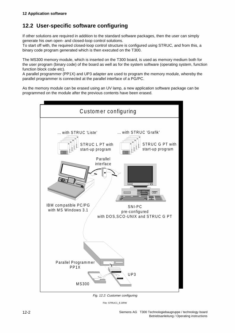
If other solutions are required in addition to the standard software packages, then the user can simplygenerate his own open- and closed-loop control solutions.To start off with, the required closed-loop control structure is configured using STRUC, and from this, abinary code program generated which is then executed on the T300.
The MS300 memory module, which is inserted on the T300 board, is used as memory medium both forthe user program (binary code) of the board as well as for the system software (operating system, functionfunction block code etc).A parallel programmer (PP1X) and UP3 adapter are used to program the memory module, whereby theparallel programmer is connected at the parallel interface of a PG/PC.
As the memory module can be erased using an UV lamp, a new application software package can beprogrammed on the module after the previous contents have been erased.
Fig. 12.2: Customer configuring
File: STRUC1_E.DRW
M S 300
U P 3
P ara lle l P rogram m erP P 1X
IB M com patib le PC /P Gwith M S Windows 3 .1
... w ith S TR U C 'L iste ' ... w ith S TR U C 'G ra fik '
S TR U C L PT withstart-up program
STR U C G PT w ithsta rt-up program
C u stom er co n fig u ring
S N I-P Cpre-configured
w ith D O S,S C O -U N IX and S TR U C G PT
P aralle lin te rface
13 Configuring the T300 for SIMOVERT 6SE70 and DC_MASTER 6RA70
Siemens AG T300 Technologiebaugruppe / technology board Betriebsanleitung / Operating instructions
13-1
13 Configuring the T300 for SIMOVERT 6SE70 and DC_MASTER 6RA70
The following instructions assume that you have prior knowledge of SIMADYN D configuring!.
When using the T300 in the drive converter, the function blocks, described in this section, must beconfigured. The configuring rules and regulations and possibilities of SIMADYN D are valid. Only theT300-specific configuring measures are presented in this Section.The function blocks, presented here, are available from software version 4.2.0 (March 95) .
The function blocks required for the „fast“ peer-to-peer protocol, are available from STRUC-softwarerelease 4.2.3!
Information regarding the notation:For the examples shown in STRUC L, the (function block) names to be assigned by the configuringengineer are shown in italics, if they are also required elsewhere in the software.Important (function block) types are printed in bold .
13.1 Master program
13.1.1 SR6 subrack
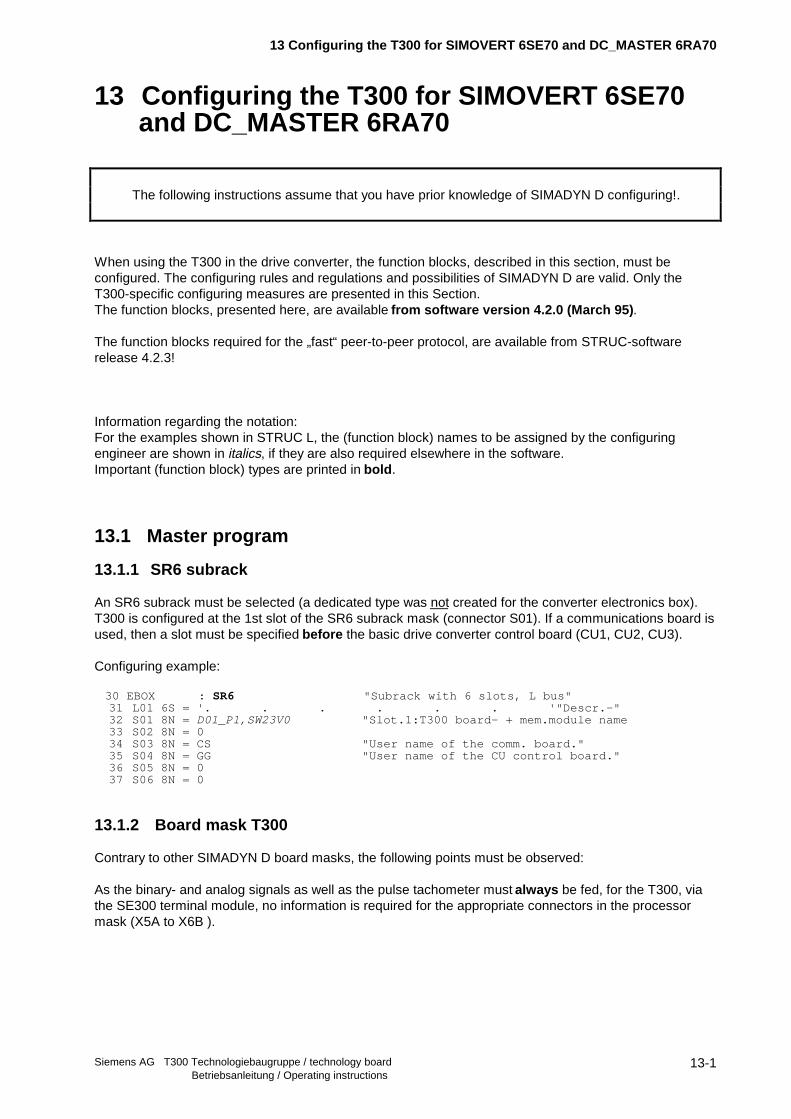
An SR6 subrack must be selected (a dedicated type was not created for the converter electronics box).T300 is configured at the 1st slot of the SR6 subrack mask (connector S01). If a communications board isused, then a slot must be specified before the basic drive converter control board (CU1, CU2, CU3).
Configuring example:
30 EBOX : SR6 "Subrack with 6 slots, L bus" 31 L01 6S = '. . . . . . '"Descr.-" 32 S01 8N = D01_P1,SW23V0 "Slot.1:T300 board- + mem.module name 33 S02 8N = 0 34 S03 8N = CS "User name of the comm. board." 35 S04 8N = GG "User name of the CU control board." 36 S05 8N = 0 37 S06 8N = 0
13.1.2 Board mask T300
Contrary to other SIMADYN D board masks, the following points must be observed:
As the binary- and analog signals as well as the pulse tachometer must always be fed, for the T300, viathe SE300 terminal module, no information is required for the appropriate connectors in the processormask (X5A to X6B ).

13 Configuring the T300 for SIMOVERT 6SE70 and DC_MASTER 6RA70
Siemens AG T300 Technologiebaugruppe / technology boardBetriebsanleitung / Operating instructions
13-2
13.1.3 T300 synchronization to the base drive cycle time
The T300 synchronization to the base drive cycle time is only approved for the MASTER DRIVES basic. A T300 synchronization to the base drive Simoreg DC_MASTER 6RA70 is not applicable.
The MASTERDRIVES base drive control board generates at the start of its 4 times basic cycle time, i.e.4*P308 (CU2), 4*P357 (CUVC) a pulse via the backplane bus LBA to T300.The T300 can synchronize its basic cycle time to this base drive cycle time.
If the clock cycle, generated by the base drive control board is to be used on the T300, an appropriate(equivalent time) constant , with the value TG = 4 * P308 or 4*P357 must be specified in the T300 boardmask at the connector for the basic cycle time T0.
T0 TG = xxx[ms]
Further, the basic clock cycle source must be configured. The backplane bus LBA, which transfers thebase drive cycle time from CUx to T300, establishes a so-called „L bus“ for the STRUC configuringlanguage.Thus, the following must be specified when synchronizing to the base drive:
T0 TG = xxx[ms] ,SRC=TL
In order to optimally harmonize data processing on the control board and T300, it is recommended that anadditional start delay is specified for the T300 cycle time. This can either be realized at the connector,base cycle time T0 using an additional attribute
T0 TG = xxx[ms] ,SRC=TL ,TDL=yyy[ms]
or using the DTS function block . The function block has the advantage, that the delay can be changedwithout making any master program changes and can therefore be made online (in this case, it is onlynecessary to reset the T300.)
13.1.4 MS300 memory module
MS300 memory modules are configured for the T300.
13.1.5 Converter log-on using the DPZ initialization block
13.1.5.1 Block description
The initialization block (IB) DPZ („Device Processor module Z“) signals to the T300 that there is a controlboard CU at its dual port RAM.
The block name (in the example „GG“), which is assigned by the configuring engineer, is specified at theCTS- and DTS connectors of other function blocks (refer below).
Configuring example:
87 GG : DPZ "IB for the control board (basic drive conv.)" 88 T0 TG = 4.8[MS],SEND=TL "Cycle time, CU provides the basic clock"

13 Configuring the T300 for SIMOVERT 6SE70 and DC_MASTER 6RA70
Siemens AG T300 Technologiebaugruppe / technology board Betriebsanleitung / Operating instructions
13-3
13.1.5.2 CU as source for the basic clock cycle
The DPZ initialization function block has a connector T0, where a transmitter for the basic clock (T0) ofthe T300 can be specified (as was shown in the previous section, the T300 can be configured so that itreceives the basic clock from the LBA backplane bus („L bus“ in STRUC).In the drive converter, this basic clock is generated by the CU control boards, via the backplane bus LBAand sent to T300, so that the following connector attribute must be specified (refer to the example below)
,SEND=TL
To calculate the cycle time dependent time constants, an (equivalent time) constant = 4 * P308 (driveconverter cycle time) must also be specified at the T0 connector. This constant corresponds to the clocksupplied from the CU.
13.1.6 Logging-on a communications board with CSZ
The initialization function block (IB) CSZ („Communication Submodule Z“) signals to the T300 that there isa communications board connected at its X135 connector (e.g. CB1, SCB1, SCB2).In order to permit configuring standards, this function block can also be configured, even if there is nocommunications board.
The function block name, to be assigned by the configuring engineer (under „CS“ in the example below),is specified at the CTS- and DTS connectors of other function blocks (refer below).
Configuring example:
85 CS : CSZ "IB for the interface board"

13 Configuring the T300 for SIMOVERT 6SE70 and DC_MASTER 6RA70
Siemens AG T300 Technologiebaugruppe / technology boardBetriebsanleitung / Operating instructions
13-4
13.1.7 Example of a master program (as excerpt)
......... 30 EBOX : SR6 "Subrack 6 slots, L bus" 31 L01 6S = '. . . . . . '"Description" 32 S01 8N = D01_P1,SW23V0 "Slot 1:T300 board- + mem. module name 33 S02 8N = 0 34 S03 8N = CS "User name of the comm. board" 35 S04 8N = GG "User name of the CU control board" 36 S05 8N = 0 37 S06 8N = 0........ 40 D01_P1 : T300 "Processor board type T300" 41 PIJ 1N = 0 "Interrupt processing FP" 42 SFJ 1N = 0 "System error FP" 43 PRX 1N = @RXD "Special communications FP - transmit" 44 PJ1 1N = CONF "1. permanent processing-FP" 45 PJ2 1N = SYNCON "2. permanent processing-FP" 46 PJ3 1N = CONTRL "3. permanent processing-FP" 47 PJ4 1N = PARA "4. permanent processing-FP"......... 52 PTX 1N = @TXD "Special communications FP - transmit" 53 T0 TG = 4[MS] "Basic cycle time" 54 T1 TS = 1 "1.sample. time *T0, gen. LB- and CB conn." 55 T2 TS = 4 "2.sample time. '' " 56 T3 TS = 0 "3.sample time. '' " 57 T4 TS = 32 "4.sample time. '' " 58 T5 TS = 64 "5.sample time. '' " 59 TY TX = T5 "System FP sample. time" 60 CCT 8R = 0 "Transmit telegram names Tx" 61 CCR 8R = 0 "Receive telegram names Tx, e.g. PKW.T4" 62 COP 8R = 0 "Op. control telegram names Tx" 63 X01 1N = 0 "1. serial interface" 64 X02 1N = PEER "2. serial interface" 65 X5A 1K < "Analog input 1" 66 X5B 1K < "Analog input 2" 67 X5C 1K < "Analog input 3" 68 X5D 1K < "Analog input 4" 69 X5E 1K < "Analog input 5" 70 X5F 1K < "Analog input 6" 71 X5G 1K < "Analog input 7" 72 X5M 4K < "Speed sensing 1" 73 X5N 4K < "Speed sensing 2" 74 X6A 8K < "Binary inputs 1, interrupt-capable" 75 X6B 8K < "Binary inputs 2, interrupt-capable" 76 X5H 1K > "Analog output 1" 77 X5J 1K > "Analog output 2" 78 X5K 1K > "Analog output 3" 79 X5L 1K > "Analog output 4" 80 X6C 8K > "Binary outputs"......... 82 SW23V0 : MS300 "Memory submod.:512K,2K EEPROM,0WS"......... 85 CS : CSZ "IB for interface board"......... 87 GG : DPZ "IB for control board (basic drive conv.)" 88 T0 TG = 4.8[MS],SEND=TL "Cycle time, CU provided basic clock".........

13 Configuring the T300 for SIMOVERT 6SE70 and DC_MASTER 6RA70
Siemens AG T300 Technologiebaugruppe / technology board Betriebsanleitung / Operating instructions
13-5
13.2 Function blocks in function packages for initialization
The function blocks described in this section@GRZDCCZ
must be configured so that the T300 can run in the drive converter.
The function blocks presented in the subsequent sectionsTFAWPRPTXTPTR@PTP@PTP01
are only configured, if the specified functions are actually required.
13.2.1 Central block @GRZ in the transmit communications FP
The „GRZ“ (drive response Z)“ function block initializes (connects) the T300 to one board, connected via adual port RAM. A @GRZ must be configured, both for the CU as well as for a communications board!
To be configured in the transmit communications FP !
Inputconn.
Type Explanation, @GRZ
CTS CR- Depending on the CPT conn., eitherthe board name of the driveconverter (refer to IB DPZ in theMP) or the board name of thecomm. board (refer to IB CSZ in theMP) must be specified.
CPT B1- =0: Basic drive converter and=1: Comm. board
should be initialized
Outputconn.
Type Explanation, @GRZ
QTS B1 Transfer status to the basic driveconverter or communications board:0: Data transmission faulted1: O.K.
YTS O2 Error code (refer to the Manual /1/Sect. 6)
Configuring example:
52 CU_DPR : @GRZ 53 CTS CR - GG 54 CPT B1 - 0 "=0: comm. with the drive conv. (GG)" 55 QTS B1 > 56 YTS O2 > 57 + 58 CS_DPR : @GRZ 59 CTS CR - CS 60 CPT B1 - 1 "=1: comm. with the comm. board" 61 QTS B1 > 62 YTS O2 >

13 Configuring the T300 for SIMOVERT 6SE70 and DC_MASTER 6RA70
Siemens AG T300 Technologiebaugruppe / technology boardBetriebsanleitung / Operating instructions
13-6
13.2.2 Dual port RAM administration using DCCZ in the standard FP
The „Device Configuration Control Z“ function block initializes and administers the communicationchannels (process data, parameters) to the base drive (CU), and a possibly available communicationsboard. It processes the heartbeat counter monitoring, and controls monitoring LEDs H2 and H3 on theT300.
It may only be configured in the standard FP and in cycle times 100ms <= Ta <= 256msIf this is not the case, initialization is not correctly executed.
Information regarding the address connectors AR, AT:A specification must be made at the AR/AT connectors of the telegram blocks or the directtransmitter/receiver, for the coupling to the basic drive converter (CU) or communications board (SCB1/2,CB1), e.g.
AR NS - ‘0’AT NS - ‘0’
Inputconn.
Type Explanation, DCCZ
DTS CR- The FB name of the IB DPZ in theMP is specified (board name of thebasic drive converter)
CTS The FB name of the IB CSZ in theMP is specified (board name of thecommunications board): A 0 mustbe entered if a communicationsboad is not used.
Outputconn.
Type Explanation, DCCZ
QTS B1 Data transmission status to thebasic drive converter orcommunications board :0: Data transmission faulted1: O.K.
Configuring example:
279 KOPINI : DCCZ 280 DTS CR - GG 281 CTS CR - CS 282 QTS B1 >

13 Configuring the T300 for SIMOVERT 6SE70 and DC_MASTER 6RA70
Siemens AG T300 Technologiebaugruppe / technology boardBetriebsanleitung / Operating instructions
13-7
13.3 Error- and alarm function block TFAW
The „Technology Faults and Warnings“ function block transfers the binary signals (V2 type) available at itsinput connectors, to the base drive as converter faults (the drive is then shutdown) or alarms.A set bit generates a fault or alarm.
When the fault/alarm cause has disappeared, the software must reset the appropriate bit. Faults are onlyacknowledged on the base drive control board.The signals present at the TFAW are not influenced by an acknowledgement. The binary values of allconnectors are transferred to the base drive at every cycle time.
Can be configured in the standard FP; multiple configuring not possible!
Inputconn.
Type Explanation, TFAW
DTS CR- Board name of the base drive (DPZin the MP)
F01 V2 Faults F116 - F131(e.g. bit 0 generates F116)
F02 Faults F132 - F147A01 Alarms A097 - A113A02 Alarms A114 - A129
Outputconn.
Type Explanation, TFAW
QTF B1 Data transmission status, faultchannel0: Faulted1: Operational
YTF O2 Error code, fault channel0: Error-free
QTA B1 Data transmission status, alarmchannel
YTA O2 Error code, alarm channelQTS B1 Data transmission status (central
administration)YTS O2 Error code (central administration)
Error codes, refer to the Manual /1/ Sect. 6!
13 Configuring the T300 for SIMOVERT 6SE70 and DC_MASTER 6RA70
Siemens AG T300 Technologiebaugruppe / technology boardBetriebsanleitung / Operating instructions
13-8
13.4 Parameter processing
Restrictions:
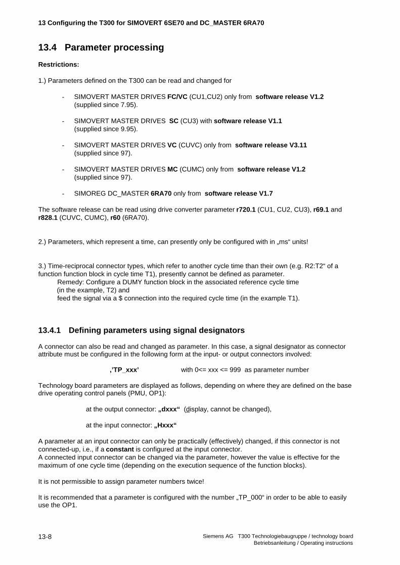
1.) Parameters defined on the T300 can be read and changed for
- SIMOVERT MASTER DRIVES FC/VC (CU1,CU2) only from software release V1.2 (supplied since 7.95).
- SIMOVERT MASTER DRIVES SC (CU3) with software release V1.1 (supplied since 9.95).
- SIMOVERT MASTER DRIVES VC (CUVC) only from software release V3.11 (supplied since 97).
- SIMOVERT MASTER DRIVES MC (CUMC) only from software release V1.2 (supplied since 97).
- SIMOREG DC_MASTER 6RA70 only from software release V1.7
The software release can be read using drive converter parameter r720.1 (CU1, CU2, CU3), r69.1 andr828.1 (CUVC, CUMC), r60 (6RA70).
2.) Parameters, which represent a time, can presently only be configured with in „ms“ units!
3.) Time-reciprocal connector types, which refer to another cycle time than their own (e.g. R2:T2“ of afunction function block in cycle time T1), presently cannot be defined as parameter.
Remedy: Configure a DUMY function block in the associated reference cycle time (in the example, T2) and
feed the signal via a $ connection into the required cycle time (in the example T1).
13.4.1 Defining parameters using signal designators
A connector can also be read and changed as parameter. In this case, a signal designator as connectorattribute must be configured in the following form at the input- or output connectors involved:
,’TP_xxx’ with 0<= xxx <= 999 as parameter number
Technology board parameters are displayed as follows, depending on where they are defined on the basedrive operating control panels (PMU, OP1):
at the output connector: „dxxx“ (display, cannot be changed),
at the input connector: „Hxxx“
A parameter at an input connector can only be practically (effectively) changed, if this connector is notconnected-up, i.e., if a constant is configured at the input connector.A connected input connector can be changed via the parameter, however the value is effective for themaximum of one cycle time (depending on the execution sequence of the function blocks).
It is not permissible to assign parameter numbers twice!
It is recommended that a parameter is configured with the number „TP_000“ in order to be able to easilyuse the OP1.

13 Configuring the T300 for SIMOVERT 6SE70 and DC_MASTER 6RA70
Siemens AG T300 Technologiebaugruppe / technology board Betriebsanleitung / Operating instructions
13-9
13.4.2 Reading and changing parameters using PRP
The connectors, defined on the T300 as parameters, can be read and changed using the „ParameterReply“ function block. This is simultaneously possible from several sources, for example, from the basedrive:
PMU operator control panel or via theserial interfaces SST1 (e.g. OP1), SST2 or fromcommunication boards (CB1, SCB2).
The PRP function block can be configured once in a standard FP and only in a samping time ≥≥ 100 ms !The parameter read and change tasks from all of the interfaces are responded to in this cycle time.
Connector types correspond generally directly to the parameter types. Several type conversions arerealized on the T300 due to the resolution and the value range required:
Connector type Parameter typeN2, E2 I4D2, T2, R2 I4 (O4 is not defined in the base drive (CU))
Inputconn.
Type Explanation, PRP
DTS CR- Board name of the base drive(refer to DPZ in the MP)
CTS Board name of the comm. board(refer to CSZ in the MP)
NP O2 Number of the existing parameters(<1000); Conn, reserves theappropriate space in theadministration tables. Moreparameters than are actuallyavailable can be specified.
LID Selecting 2 different parameternames at the string connectors ofthe TXT-FBs configured tests;is also used to select the language:
0: Selecting texts from theconnectors designated with the ‘TPTxxx’ attribute(xxx: Parameter number);
<>0: Selecting the connectors withthe Tptxxx attribute
MEN Defined access rights of allparameters:0: Parameters can be read andchanged ,1: Can only be be read
Outputconn.
Type Explanation, PRP
NPF O2 Number of configured parametersNTF Number of available parameter
namesNPD Number of parameter numbers
which have been assigned twiceNTD Number of parameter names which
have been assigned twiceNPE Number of the parameters which
have not found space in theadministration list as the NP conn. istoo small
NTE Number of unavailableparameter names, because notconfigured with TXT function block
YTB Error code, basic converter channelQTB B1 Operating status, basic converter
channel:0:Faulted1:Ready
YTC O2 Error code, comm. board channelQTC B1 Operating status,
comm. board channelYTK O2 Error code, operator panel channelQTK B1 Operating status, operating panel
channelYTS O2 Error code (central administration)QTS B1 Operating status (central
administration)
Error code, refer to the Manual (Section 6 /1/)

13 Configuring the T300 for SIMOVERT 6SE70 and DC_MASTER 6RA70
Siemens AG T300 Technologiebaugruppe / technology boardBetriebsanleitung / Operating instructions
13-10
13.4.3 Parameter names defined using TXT
Using the TXT text function block, parameters, defined using the signal designator, can be assigned up to2 parameter names.The assignment of the parameter names specified here to the parameter numbers is realized via theattributes attached to the parameter names in the following form:
T1 NS - ‘Drehzahlistwert’ ,’TPT001’or
T2 NS - ‘speed actual val’ ,’TPt001’
The two different parameter names, assigned to a parameter number are selected via the LID connectorof the PRP function block (refer there).
Inputconn.
Type Explanation, TXT
T1 NS- Parameter name 1T2 Parameter name 2... ...T16 Parameter name 16
Outputconn.
Type Explanation, TXT
None!
13.4.4 Configuring example, parameters
22 PARAMS : PRP "Parameter function block" 23 DTS CR - GG 24 CTS CR - CS 25 NP O2 - 200 "No. of parameters" 26 LID O2 - 0 27 MEN B1 < 0 "Inhibit par. changes" 28 NPF O2 > "Number of found par." 29 NTF O2 > "Number of texts found" 30 NPD O2 > 31 NTD O2 > 32 NPE O2 > "Number n. of par. entered" 33 NTE O2 > "Number n. of texts entered" 34 YTB O2 > 35 QTB B1 > 36 YTC O2 > 37 QTC B1 > 38 YTK O2 > 39 QTK B1 > 40 YTS O2 > 41 QTS B1 >................. 55 P001 : DUMY 56 X N2 < 1.1,SCAL=163.84 "Software release" 57 Y N2 > ,SCAL=163.84,FORM=1 ,'TP_001'................. 64 TEX000 : TXT 65 T1 NS - 'Synch. contr. SW21' ,'TPT001' 66 T2 NS - 'Language D/E=1/2' ,'TPT002' 67 T3 NS - 'Spec handle. V2/B1','TPT003' 68 T4 NS - '' 69 T5 NS - 'Encoder par. SLAVE','TPT018' 70 T6 NS - 'Encoder par. MASTE','TPT019' 71 T7 NS - '' 72 T8 NS - '' 73 T9 NS - 'Enc. pulse No. SLAVE','TPT010' 74 T10 NS - 'Enc. pulse No. MASTE','TPT011'................. 80 T16 NS - 'Pos. act. val. MASTER' ,'TPT017'

13 Configuring the T300 for SIMOVERT 6SE70 and DC_MASTER 6RA70
Siemens AG T300 Technologiebaugruppe / technology board Betriebsanleitung / Operating instructions
13-11
13.5 Base drive parameters via the comm. board with PTR
If parameters of a base drive (CUx) are to be read or changed via a communications board, the„Parameter Transport“ PTR function block must be configured. It transfers the parameter orders andparameter replies via the T300, located between the communications board and the base drive.
The PTR function block is configurable once in a standard FP.
Inputconn.
Type Explanation, PTR
DTS CR- Board name of the basic converter(refer to IB DPZ in the MP)
CTS Board name of the comm. board(refer to IB CSZ in the MP)
Outputconn.
Type Explanation, PTR
YTS O2 Error codeQTS B1 Operating status:
0: Faulted1: Ready
Error code, refer to the Manual /1/ section 6!
Configuring example:
269 TRANS : PTR "Param.transport CU <-> CBx" 270 DTS CR - GG 271 CTS CR - CS 272 QTS B1 > 273 YTS O2 >
13.6 Peer-to-peer coupling
A fast serial coupling to partners, for example, T300 and SCB2 boards for SIMOVERT Master Drives aswell as to SIMOVERT P 6SE12 and SIMOREG K 6RA24 drives can be established using the „Peer-to-peer“ coupling.
For baud rates up to 115.2 kbaud, a maximum of 5 data words can be transferred in full duplex.
Only 1 telegram can be defined in the transmit direction and receive direction, i.e., only one transmit- andreceive function block may be configured.
The net data length of the transmit- and receive function blocks can be different. However, a receiver onlyaccepts data from a received telegram, if the configured length corresponds with the received telegramlength (LTW- or LT connector).
Different versions are available depending on the particular STRUC version:
STRUC V4.2.3: Configuring with function blocks @PTP01, CTPP, CRPP(max. baud rate: 115.2kbaud; requires little computation time)
for V4.2.1 to be asked (special libaries KFSLIB, FBSLT1 required)!
STRUC V4.2, V4.2.1 and V4.2.2: Configuring with function block @PTP (max. baud rate: 38.4kbaud)

13 Configuring the T300 for SIMOVERT 6SE70 and DC_MASTER 6RA70
Siemens AG T300 Technologiebaugruppe / technology boardBetriebsanleitung / Operating instructions
13-12
13.6.1 Configuring a peer-to-peer telegram with @PTP01, CTPP, CRPP
A peer-to-peer protocol is avaialble with STRUC release V4.2.3, which
- has a high baud rate,- has minimum telegram delay times and- only loads the T300 with low computation time.
Initialization:
The @PTP01 function block must be configured in the special FP transmit .The cycle time can be freely selected, as it only takes over the initialization of the serial interface..
As a result of the 4-wire RS485 interface, the peer-to-peer protocol can only run at connector X134 , i.e.serial interface 2 (connector X02 of the board mask).This „connector“ X02 must be configured, togetherwith the T300 board names at the CTS connectors of @PTP01, CTPP and CRPP.
Input-conn.
Type Explanation @PTP01
CTS CR- T300 board name (refer to MP) and,separated by a point, connector„.X02“
BDR O2 Baud rate(coding as for the SCB board):0: 150 bit/s1: 300 bit/s2: 600 bit/s3: 1200 bit/s4: 2400 bit/s5: 4800 bit/s6: 9600 bit/s7: 19200 bit/s8: 38400 bit/s9: 57600 bit/s10: 76800 bit/s11: not permitted (=93750 of theSCB)12: 115200 bit/s
Outp. -conn.
Type Explanation @PTP01
QTS B1 Operating status:0: Faulted1: O.K.
YTS O2 Error/status display:
7B90H/31632dec:Init still running (wait for KSIPP0)
7B91H/31633dec: Init error: KML is full
7B92H/31634dec: Connector is not X02
7B93H/31635dec: Excessive baud rate ID (>12)
7B94H/31636dec: Baud rate ID 11 (93750Bd) notpermitted
7B95H/31637dec: other KSIPP0- errors (e.g. DUSTinit)

13 Configuring the T300 for SIMOVERT 6SE70 and DC_MASTER 6RA70
Siemens AG T300 Technologiebaugruppe / technology board Betriebsanleitung / Operating instructions
13-13
Transmit:
Up to 5 data words can be sent using function block CTPP. It has to be configured in a standard FP.
A send telegram operation is started immediately within the function block processing. The telegram of theprevious cycle time must have been completely transmitted. Thus, it is recommended to adapt the baudrate as well as the telegram length (both together specify the telegram transmission time) to the cycle time(refer below, telegram transmission time table).
Computation time required for a 5-word telegram (including the time to transmit all characters): 230µsec(this includes a processing time of 28µsec /data word.)
Inputconn.
Type Explanation CTPP
CTS CR- T300 board name (refer to MP) and,separated by a point, connector„.X02“
LEM O2- Error message limit: If the telegramcannot be sent within the specifiednumber of cycle times (e.g.: Due toa low baud rate with respect to thecycle time), this is signaled in QTS(=0) and YTS
LTW O2- The net data word quantity to betransmitted (1 word = 2 bytes);maximum number:0 to 5 (from 1.96A change is only effective after thesystem has been powered-downand powered-up again!
EN B1 1 enables transmit,0 inhibits transmit
X1 N2 1st data wordX2 N2 2nd data wordX3 N2 3rd data wordX4 N2 4th data wordX5 N2 5th data word
Outp.conn.
Type Explanation CTPP
QTS B1 Operating status:0: Faulted1: O.K.
YTS O2 Error/status display:
7D04H/32004dec:Telegram length configured too long
7D08H/32008dec:Transmitter inhibited (EN conn.)
7D09 H/32009dec:Transmitter still full
7D10H/32016dec:Init still running (wait for KSIPP0)
7D11H/32017dec:KM name double (configuring)
7D12H/32018dec:Init error: Refer to KML
7D13H/32019dec:Init ready, wait for 1st telelgram, aslong as LEM>0
7D14H/32020dec:LTW=0

13 Configuring the T300 for SIMOVERT 6SE70 and DC_MASTER 6RA70
Siemens AG T300 Technologiebaugruppe / technology boardBetriebsanleitung / Operating instructions
13-14
Receive:
Telegrams with up to 5 data words can be received with the CRPP function block. It has to be configuredin a standard FP.
The telegram is received in the background, asynchronously to the cycle time of the receive functionblock. The cycle time of the receive function block is therefore the maximum delay time between thetelegram being received and the received data being processed.
Computation time required for a 5-word telegram (including all characters being received): 267 µsec(this includes a processing time of 34 µsec/data word).
Inputconn.
Type Explanation CRPP
CTS CR- T300 board name (refer to MP) and,separated by a point, connector„.X02“
LEM O2- Error message limit: If a correcttelegram has not been receivedwithin the specified number of cycletimes (e.g.: incorrect length), this issignaled in QTS (=0)
LTW O2- The net data word quantity to betransmitted (1 word = 2 bytes);maximum number: 5A change is only effective after thesystem has been powered-downand powered-up again!
Outputconn.
Type Explanation CRPP
Y1 N2 1st data wordY2 N2 2nd data wordY3 N2 3rd data wordY4 N2 4th data wordY5 N2 5th data wordQTS B1 Operating status:
0: Faulted1: O.K.
YTS O2 Error/status display:
7D00H/32000dec:no telegram received after LEMexpired
7D01H/32001dec:BCC error, as generally thetelegram length of the transmitter isgreater than that of the receiver
7D02H/32002dec:Telegram length of the receiver isgreater than that of the transmitter
7D03H/32003dec:Baud rate possibly incorrect
7D04H/32004dec:Excessive telegram lengthconfigured.
7D10H/32016dec:Init still running (wait for KSIPP0)
7D11H/32017dec:KM name double (configuring)
7D12H/32018dec:Init error: refer to KML
7D13H/32019dec:Init ready, wait for first telegram, aslong as LEM>0
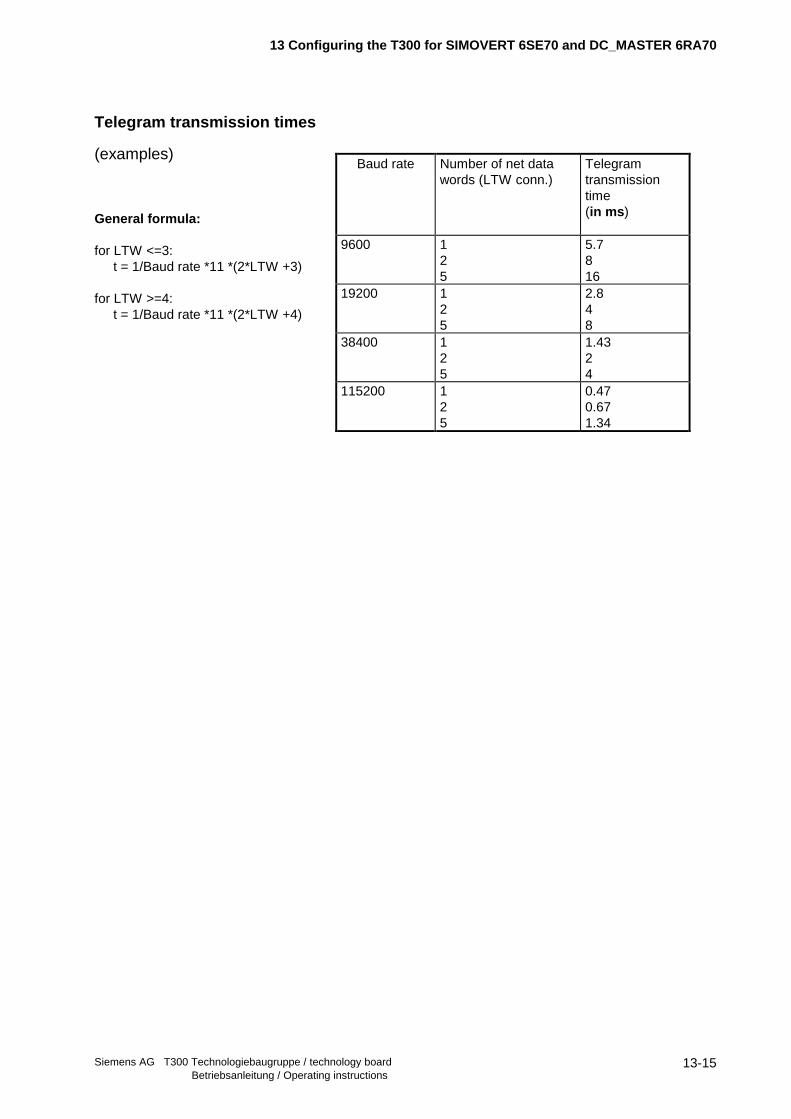
13 Configuring the T300 for SIMOVERT 6SE70 and DC_MASTER 6RA70
Siemens AG T300 Technologiebaugruppe / technology board Betriebsanleitung / Operating instructions
13-15
Telegram transmission times
(examples)
General formula:
for LTW <=3:t = 1/Baud rate *11 *(2*LTW +3)
for LTW >=4:t = 1/Baud rate *11 *(2*LTW +4)
Baud rate Number of net datawords (LTW conn.)
Telegramtransmissiontime (in ms )
9600 125
5.7816
19200 125
2.848
38400 125
1.4324
115200 125
0.470.671.34
13 Configuring the T300 for SIMOVERT 6SE70 and DC_MASTER 6RA70
Siemens AG T300 Technologiebaugruppe / technology boardBetriebsanleitung / Operating instructions
13-16
13.6.2 Peer-to-Peer Communication in Version V4.2 / V4.2.1 / V4.2.2 with @PTP
In STRUC-Version V4.2, V4.2.1 and V4.2.2, the Peer-to-Peer communication has to be realized bymeans of the @PTP function block. The data interchange can be configured according to the normalSIMADYN D mechanism, i.e. using the Telegram Function Blocks @CTD/@CRD oder directTransmit/Receive blocks.
In V4.2.3, this configuring method for the Peer-configuring (FB @PTP) is no longer supported!
13.6.2.1 Configuring a Peer-to-Peer Telegram in Version V4.2 / V4.2.1 / V4.2.2
Due to the 4-wire RS485-interface, the Peer-to-Peer-Protocol is only available on the T300 ConnectorX134, i.e. on Com Port 2 (Connector X02 of the Hardware-Module Mask). This „Connector“ X02 and theT300 Board Name have to be hooked up to the CTS-Connectors of @PTP, @CTT/@CRT or the directTransmit/Receive Blocks respectively.
Only one telegram in transmit direction and one telegram in receive direction can be defined. This is thereason why only one Send and one Receive Block can be configured at maximum. At the AddressConnectors AT/AR, differring (Telegram-) Names have to be noted as arbitrary strings.
Up to 5 Net-Data Words can be transferred. The net-data length of Transmit and Receive Blocks candiffer. But a reciever only accepts data from a received telegram if the configured receive-telegram length(LT-Connector, e.g. of the @CRT Block) equals the length of the actually received telegram..
The @PTP block must be configured within the „Send“ Communications FB and in sampling timesbetween 32 ms and 255 ms . The configured sampling time does not influence the transfer speed.

13 Configuring the T300 for SIMOVERT 6SE70 and DC_MASTER 6RA70
Siemens AG T300 Technologiebaugruppe / technology board Betriebsanleitung / Operating instructions
13-17
Input-Conn.
Type Explanation @PTP
CTS CR- T300-Board Name (refer to. MP)and – separated by a dot - „.X02“connector
BDR O2 Baud Rate with the follwing code:0: 300 Bit/s1: 600 Bit/s2: 1200 Bit/s3: 2400 Bit/s4: 4800 Bit/s5: 9600 Bit/s6: 19200 Bit/s7: 38400 Bit/s(differs from @PTP01!)
TBM Telegram Timeout Time(„Tlg.-Breakdown-Monitoring“);In case of expiration, the transceiverwill be disabled. This makes amonitoring and a „BreakdownControl“ of a closed multi-dropPeer-Ring possible.Setting range: 0 to 32000msThe timeout monitoring is startedwith power-on!
TWU Alarm Cycle Time(„Time Wake Up“)Setting rage: 1 to 32000ms
Outp. -Conn.
Type Explanation @PTP
ECL O2 Error Class; Evaluation incombination with the ECO-Connector;ECL>0: Hardware/Software Error
ECO Error Code:ECO=ECL=0: no error;ECO>0 and ECL=0: ConfiguringError
CDM B1 State of the Communication:0: Initialization is running1: Telegram Interchange is running
QTS Operating Status:0: Error pending1: no Error
Error Codes: Refer to Manual (Chapter 6 /1/) !
13.6.2.2 Principle of Operation and Time Response in Version V4.2 , V4.2.1 and V4.2.2
After the „Alarm Time“ specified at Connector TWU has been expired, the function block processes anevetually received telegram and makes the telegram’s net data available for the Receive FunctionBlock(s) in the „Normal“ FPs. If the Send Funktion Blocks have provided net data in the meantime, thisdata will be „packed“ now into a Peer-to-Peer telegram and transmitted.This Alarm Cycle runs asynchronously to the sample times!
Set the alarm time as short as possible for minimizing the dead times caused by the alarm processing.This maximizes the time which can be used for the effective data transfer. The minimum allowable valueof the alarm time is 2 ms due to the processing time of approx. 1 ms for the transmit and the receiveroutine. So enough processing time will be available for the normal tasks.
Only transmit data actually generated by the Transmit Function Blocks is transmitted. If long alarm andsampling times and high baud rates (i.e. short telegram transfer times) are configured, telegramm pauseintervals can occur on the transfer line.
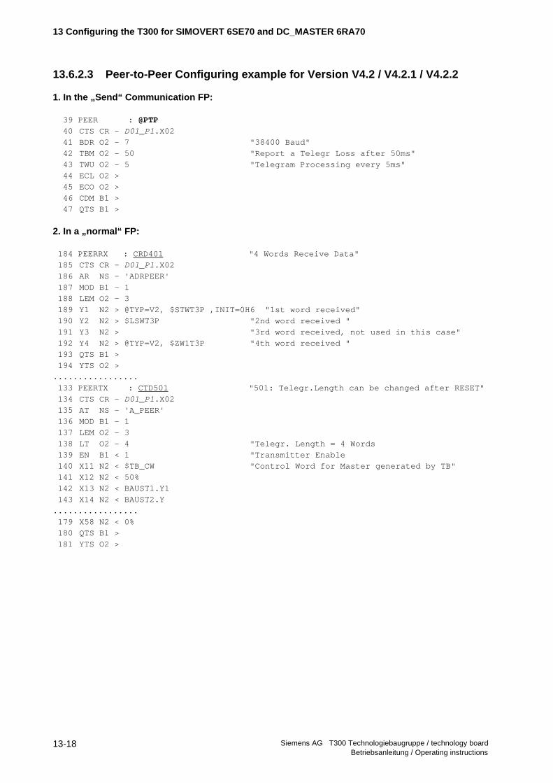
13 Configuring the T300 for SIMOVERT 6SE70 and DC_MASTER 6RA70
Siemens AG T300 Technologiebaugruppe / technology boardBetriebsanleitung / Operating instructions
13-18
13.6.2.3 Peer-to-Peer Configuring example for Version V4.2 / V4.2.1 / V4.2.2
1. In the „Send“ Communication FP:
39 PEER : @PTP
40 CTS CR - D01_P1.X02
41 BDR O2 - 7 "38400 Baud"
42 TBM O2 - 50 "Report a Telegr Loss after 50ms"
43 TWU O2 - 5 "Telegram Processing every 5ms"
44 ECL O2 >
45 ECO O2 >
46 CDM B1 >
47 QTS B1 >
2. In a „normal“ FP:
184 PEERRX : CRD401 "4 Words Receive Data"
185 CTS CR - D01_P1.X02
186 AR NS - 'ADRPEER'
187 MOD B1 - 1
188 LEM O2 - 3
189 Y1 N2 > @TYP=V2, $STWT3P ,INIT=0H6 "1st word received"
190 Y2 N2 > $LSWT3P "2nd word received "
191 Y3 N2 > "3rd word received, not used in this case"
192 Y4 N2 > @TYP=V2, $ZW1T3P "4th word received "
193 QTS B1 >
194 YTS O2 >
.................
133 PEERTX : CTD501 "501: Telegr.Length can be changed after RESET"
134 CTS CR - D01_P1.X02
135 AT NS - 'A_PEER'
136 MOD B1 - 1
137 LEM O2 - 3
138 LT O2 - 4 "Telegr. Length = 4 Words
139 EN B1 < 1 "Transmitter Enable
140 X11 N2 < $TB_CW "Control Word for Master generated by TB"
141 X12 N2 < 50%
142 X13 N2 < BAUST1.Y1
143 X14 N2 < BAUST2.Y
.................
179 X58 N2 < 0%
180 QTS B1 >
181 YTS O2 >

13 Configuring the T300 for SIMOVERT 6SE70 and DC_MASTER 6RA70
Siemens AG T300 Technologiebaugruppe / technology board Betriebsanleitung / Operating instructions
13-19
13.7 Erasing the EEPROM
The T300 parameters („H-Parameters“) are reset to their factory values by erasing the nonvolatileEEPROM parameter memory chip loctated on the MS300 board..
Also in non-standard situations, it can become necessary to erase the EEPROM, e.g. if
- all modifications made should be made „undone“,(This can also be performed with an EPE funktion block if such a block has been configuredand the board is still functionable)
- if the T300 doesn’t longer start-up correctly after unauthorized modifications of connectors orparameters had been made.
- if an EEPROM overflow has been occurred.
The T300 stores all technology parameters (H- or 1xxx-parameters) received from a PC download file intothe T300 EEPROM regardless of whether the parameter value is differring from the factory setting or not.This is due to the SIMADYN D operating system. According to our experience, approx. 250 to 290parameters can be stored in the EEPROM until an overflow occurs. An EEPROM overflow is signalled bythe SIMOVIS message "Write Error" or, during download, by the message "Not Written".
Please Note: In the EEPROM, binary quantities occupy 6 Bytes, word quantities 7 Bytes and double-wordquantities 9 Bytes. The hardware EEPROM chip mounted on the MS300 memory module has aparameter capacity of 2000 Bytes.
- If your T300 configured software package has more than 250 to 280 H-Parameters, it is an imperativeprocedure to generate a „File of Changed Parameters“ (containing only those parameters which aredifferring from the factory settings) which can be used for an error-free parameter download withoutEEPROM overflow.
13.7.1 Erasing the EEPROMs if an overflow has been occurred
- SIMOVIS signals a "KON: Writing Error" message if an EEPROM overflow occurs when editing theSIMOVIS parameter.
- SIMOVIS signals a „Not Written xxx“ message if an EEPROM overflow occurs during a downloadprocedure.
- The EEPROM can only be erased when the storage mode „Storing in EEPROM“ is changed to „Storingin RAM“ by clicking on the small RAM symbol.
- Afterwords use the respective H-Parameter for erasing the EEPROM. The number of this „EraseEEPROM“ parameter depends on the T300 software Configured Package. Refer to the appropriatemanual of your Standard Configured Package (e.g. MS320...380) or the SIMADYN D Function-BlockCatalog to get information on the correct parameter settings for the EEPROM erasing procedure.Subsequently please switch the electronics power supply off and on again.

13 Configuring the T300 for SIMOVERT 6SE70 and DC_MASTER 6RA70
Siemens AG T300 Technologiebaugruppe / technology boardBetriebsanleitung / Operating instructions
13-20
13.7.1.1 Erasing the EEPROM in case of memory overflow by means of the Hex-Monitor
The EEPROM also can be erased by means of the SIMADYN D Hex-Monitor .
In this case two EEPROM Bytes have to be modified via the Hex-Monitor according to the followingprocedure:
1. Connect a COM port of your PC to terminal X132 of the T300. Configure your COM port to 9,6kBd andNo Parity Bit by one of the following two alternatives:
a) Use the SIMADYN D SERVICE-Programm: Select the „Hex/Debug-Monitor“ option in the„Activities“ menue.
b) Launch a terminal emulation program on your PC, e.g. the „Terminal“ programm with DEC VT100emulation if you are using WINDOWS.
2. Start the Hex-Monitor:Push the small pushbutton on the T300 board during Power-On and keep it pressed until operating
state °003 is displayed. A Hex-Monitor start-up message should now be displayed on the screen.
3. Use the „S“ command ( „Subsitute“) to change the following memory locations in the EEPROMmemory:
7C00:0=AA7C00:2=0 (End Specifier)
Type in the following Hex-Monitor command sequence (strictly adhere to the noted command syntax;<CR> designates the Enter key. XX designates any two arbitrary hexadecimal digits):
S7C00:0 <CR>
Now you will be prompted on the screen. Subsequently type in the following commands:
7C00:0 XX AA, input AA, proceed7C00:1 XX , go to the next location7C00:2 XX 0, input 0 and proceed7C00:3 XX . termination
4. Switch the the electronics power supply OFF and ON again.
13.7.2 Erasing the EEPROM for restoring the factory settings:
- Erase the EEPROM according to chapter 13.7.1. Switching over the storage mode from EEPROM toRAM is not necessary.
After the EEPROM is erased and power has beeen switched on again, it is highly recommended toreset those parameters back to „0“ which have been used to accomplish the erasing procedure.

14 Literature
Siemens AG T300 Technologiebaugruppe / technology board Betriebsanleitung / Operating instructions
14-1
14 Literature
/1/ SIMADYN D „General diagnostics“Item No.: 465 983.9010.00

14 Literature
Siemens AG T300 Technologiebaugruppe / technology boardBetriebsanleitung / Operating instructions
14-2

15 Order numbers
Siemens AG T300 Technologiebaugruppe / technology board Betriebsanleitung / Operating instructions
15-1
15 Order numbers
Type: Order No. (MLFB) Designation
T300-
HWpackage
6SE7090-0XX87-4AH0 Hardware package (complete, without software (MSxxx)!)
T300 6SE7090-0XX84-0AH2 T300 processor board
SE300 6SE7090-0XX84-3EH0 Terminal function block for T300
SC58 6DD 3461-0AB0 Round cable to transfer analog- and pulse encoder signalsbetween SE300 and T300, shielded, 40 core
SC60 6DD 3461-0AE0 Round cable to transfer binary signals between SE300 andT300, shielded, 34-core
MS300 6SE7098-0XX84-0AH0 MS300 memory module, empty
MS320 6SE7098-2XX84-0AH0 MS300 memory module with standard software package„Axial winder“ AW
MS340 6SE7098-4XX84-0AH0 MS300 memory module with standard software package„Angular synch.“ WGL
MS360 6SE7098-6XX84-0AH0 S300 memory module with standard software package „Multi-motor drive“ MMA
MS380 6SE7098-8XX84-0AH0 S300 memory module with standard software package„Positioning“ POS
Doc. T300 6SE7087-6CX84-0AH1 Description of the T300 board and general software(dt.,engl.)
Doc. T300 6SE7087-7CX84-0AH1 Description of the T300 board and general software (fr.)
Dok. AW 6SE7080-0CX84-2AH1 Description, standard app. software. axial winder (dt.)
Dok. WGL 6SE7080-0CX84-4AH1 Description, standard app. software. ang. synch. (dt.)
Dok. MMA 6SE7080-0CX84-6AH1 Description, standard app. software.multi-motor drive (dt.)
Dok. POS 6SE7080-0CX84-8AH1 Description, standard app. software. positioning (dt.)
Doc. AW 6SE7087-6CX84-2AH1 Description, standard app. software. axial winder (engl.)
Doc. WGL 6SE7087-6CX84-4AH1 Description, standard app. software. ang. synch. (engl.)
Doc. MMA 6SE7087-6CX84-6AH1 Description, standard app. software.multi-motor drive (engl.)
Doc. POS 6SE7087-6CX84-8AH1 Description, standard app. software. positioning (engl.)
Doc. WGL 6SE7087-7CX84-4AH1 Description, standard app. software. ang. synch. (fr.)

15 Order numbers
Siemens AG T300 Technologiebaugruppe / technology boardBetriebsanleitung / Operating instructions
15-2
MD320 6SW1798-2XX84-0AH0 MS320 standard app. software axial winder on a 31/2 inchfloppy disk(without documentation)
MD340 6SW1798-4XX84-0AH0 MS340 standard app. software angular synchronouscontrol on a 31/2 inch floppy disk(without documentation)
MD360 6SW1798-6XX84-0AH0 MS360 standard app. software multi-motor drive on a 31/2inch floppy disk(without documentation)
MD380 6SW1798-8XX84-0AH0 MS380 standard app. software positioning on a 31/2 inchfloppy disk(without documentation)

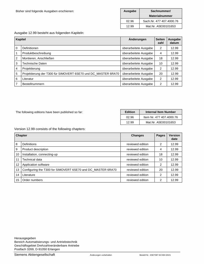
HerausgegebenBereich Automatisierungs- und AntriebstechnikGeschäftsgebiet Drehzahlveränderbare AntriebePostfach 3269, D-91050 Erlangen
Siemens Aktiengesellschaft Änderungen vorbehalten Bestell-Nr.: 6SE7087-6CX84-0AH1
Bisher sind folgende Ausgaben erschienen: Ausgabe Sachnummer/
Materialnummer
02.96 Sach.Nr. 477 407.4000.76
12.99 Mat.Nr. A5E00101653
Ausgabe 12.99 besteht aus folgenden Kapiteln:
Kapitel Änderungen Seitenzahl
Ausgabedatum
0 Definitionen überarbeitete Ausgabe 2 12.99
1 Produktbeschreibung überarbeitete Ausgabe 4 12.99
2 Montieren, Anschließen überarbeitete Ausgabe 18 12.99
3 Technische Daten überarbeitete Ausgabe 10 12.99
4 Projektierung überarbeitete Ausgabe 2 12.99
5 Projektierung der T300 für SIMOVERT 6SE70 und DC_MASTER 6RA70 überarbeitete Ausgabe 20 12.99
6 Literatur überarbeitete Ausgabe 2 12.99
7 Bestellnummern überarbeitete Ausgabe 2 12.99
The following editions have been published so far: Edition Internal Item Number
02.96 Item Nr. 477 407.4000.76
12.99 Mat.Nr. A5E00101653
Version 12.99 consists of the following chapters:
Chapter Changes Pages Versiondate
8 Definitions reviewed edition 2 12.99
9 Product description reviewed edition 4 12.99
10 Installation, connecting-up reviewed edition 18 12.99
11 Technical data reviewed edition 10 12.99
12 Application software reviewed edition 2 12.99
13 Configuring the T300 for SIMOVERT 6SE70 and DC_MASTER 6RA70 reviewed edition 20 12.99
14 Literature reviewed edition 2 12.99
15 Order numbers reviewed edition 2 12.99