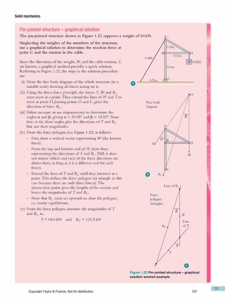
Embed Size (px)
Citation preview

httpswwwcrcpresscom
Bestselling Civil and Mechanical Engineering Textbooks
A CRC Press Sampler
C R C P R E S S T A Y L O R amp F R A N C I S
Copyright Taylor amp Francis Not for distribution 1
httpswwwcrcpresscom
ContentsHistory and Overviewfrom Fracture Mechanics Fundamentals and Applications 4th Edition by TL Anderson
Basic Electrical Engineering Principlesfrom Electrical Circuit Theory and Technology 6th Edition by John Bird
Health and Safety in Electrical Installationfrom Electrical Installation Work Level 2 by Peter Roberts and Mark Baker
Partial Fractionsfrom Higher Engineering Mathematics 8th Edition by John Bird
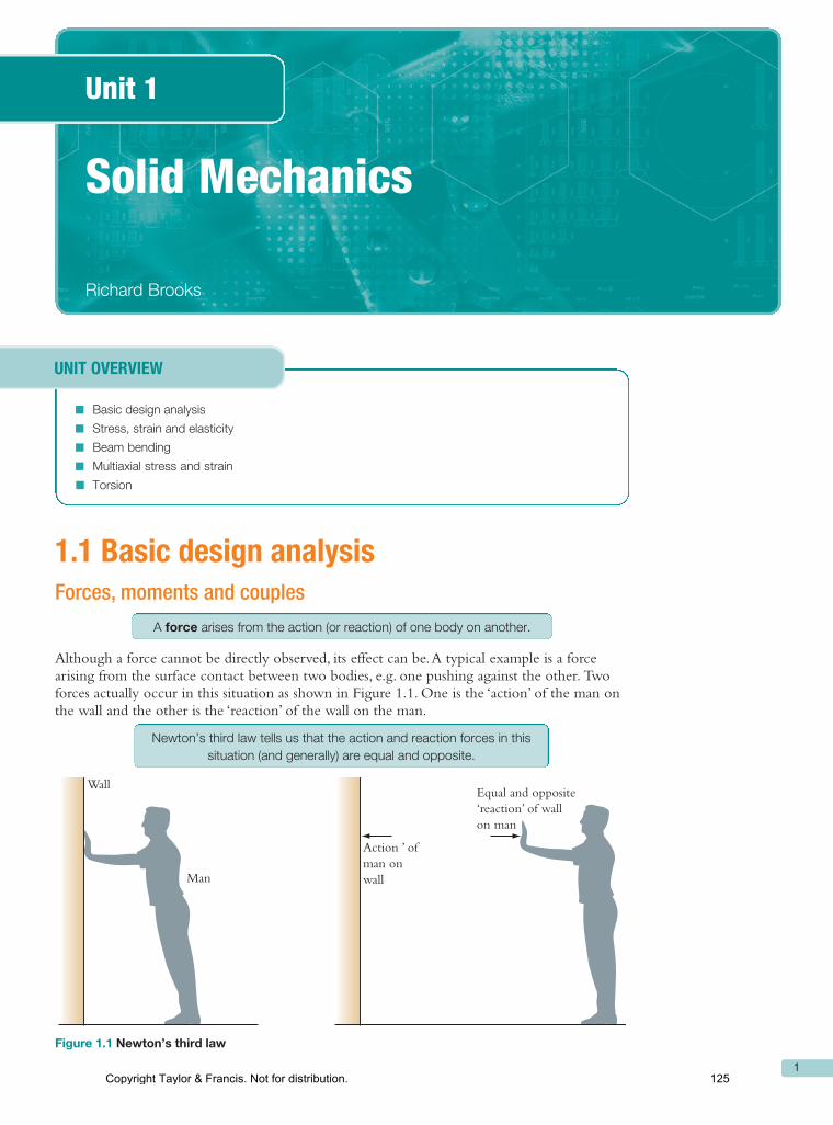
Basic Design Analysisfrom An Introduction to Mechanical Engineering by Michael Clifford Kathy Simmon and Philip Shipway
Request an Inspection CopyAll of the books included in this Sampler are available as Inspection Copies Visit our website to request your copy
Copyright Taylor amp Francis Not for distribution 2
3
23
28
118
125
3
1History and Overview
Fracture is a problem that society has faced for as long as there have been man-made structures The problem may actually be worse today than in previous centuries because more can go wrong in our complex technological society Major airline crashes for instance would not be possible without modern aerospace technology
Fortunately advances in the eld of fracture mechanics have helped to offset some of the potential dangers posed by increasing technological complexity Our understanding of how materials fail and our ability to prevent such failures has increased considerably since World War II Much remains to be learned however and the existing knowledge of fracture mechanics is not always applied when appropriate
While catastrophic failures provide income for attorneys and consulting engineers such events are detrimental to the economy as a whole An economic study [1] estimated the annual cost of fracture in the United States in 1978 at $119 billion (in 1982 dollars) about 4 of the gross national product Furthermore this study estimated that the annual cost could be reduced by $35 billion if current technology were applied and that further fracture mechanics research could reduce this gure by an additional $28 billion
11 Why Structures Fail
The cause of most structural failures generally falls into one of the following categories
1 Negligence during design construction or operation of the structure2 Application of a new design or material which produces an unexpected (and
undesirable) result
In the rst instance the existing procedures are sufcient to avoid failure but are not followed by one or more of the parties involved due to human error ignorance or willful misconduct Poor workmanship inappropriate or substandard materials errors in stress analysis and operator error are examples of where appropriate technology and experience are available but not applied
The second type of failure is much more difcult to prevent When an ldquoimprovedrdquo design is introduced there are invariably factors that the designer does not anticipate New mate-rials can offer tremendous advantages but also have potential problems Consequently a new design or material should be placed into service only after extensive testing and analysis Such an approach will reduce the frequency of failures but not eliminate them entirely there may be important factors that are overlooked during testing and analysis
One of the most famous Type 2 failures is the brittle fracture of the World War II Liberty ships (see Section 122) These ships which were the rst to have an all-welded hull could be fabricated much faster and cheaper than earlier riveted designs but a signicant num-ber of these vessels sustained serious fractures as a result of the design change Today
Copyright Taylor amp Francis Not for distribution 3
4 Fracture Mechanics Fundamentals and Applications
virtually all steel ships are welded but sufcient knowledge was gained from the Liberty ship failures to avoid similar problems in present structures
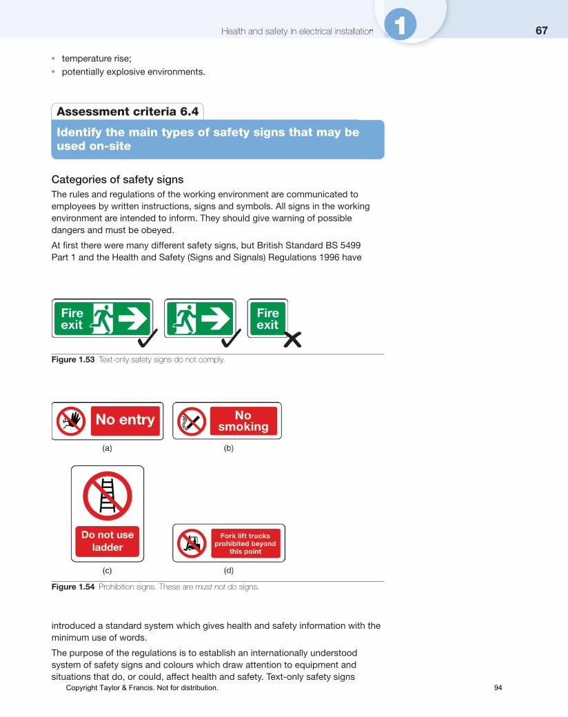
However knowledge must be applied in order to be useful Figure 11 shows an example of a Type 1 failure where poor workmanship in a seemingly inconsequential structural detail caused a more recent fracture in a welded ship In 1979 the Kurdistan oil tanker broke completely into two while sailing in the North Atlantic (Garwood SJ private com-munication 1990) The combination of warm oil in the tanker with cold water in contact with the outer hull produced substantial thermal stresses The fracture initiated from a bilge keel that was improperly welded The weld failed to penetrate the structural detail resulting in a severe stress concentration Although the hull steel had adequate toughness to prevent fracture initiation it failed to stop the propagating crack
Polymers which are becoming more common in structural applications provide a num-ber of advantages over metals but also have the potential for causing Type 2 failures For example polyethylene (PE) is currently the material of choice in natural gas transporta-tion systems in the United States One advantage of PE piping is that maintenance can be performed on a small branch of the line without shutting down the entire system a local area is shut down by applying a clamping tool to the PE pipe and stopping the ow of gas The practice of pinch clamping has undoubtedly saved vast sums of money but has also led to an unexpected problem
In 1983 a section of 4 in diameter PE pipe developed a major leak The gas collected beneath a residence where it ignited resulting in severe damage to the house Maintenance records and a visual inspection of the pipe indicated that it had been pinch clamped 6 years earlier in the region where the leak developed A failure investigation [2] concluded that the pinch clamping operation was responsible for the failure Microscopic examina-tion of the pipe has revealed that a small aw apparently initiated on the inner surface of the pipe and grew through the wall Figure 12 shows a low magnication photograph of the fracture surface Laboratory tests simulated the pinch clamping operation on sections of the PE pipe small thumbnail-shaped aws (Figure 13) formed on the inner wall of the pipes as a result of the severe strains that were applied Fracture mechanics tests and analyses [23] have indicated that stresses in the pressurized pipe were sufcient to cause the observed time-dependent crack growth that is growth from a small thumbnail aw to a through-thickness crack over a period of 6 years
The introduction of aws in PE pipe by pinch clamping represents a Type 2 failure The pinch clamping process was presumably tested thoroughly before it was applied in
(a) (b)
FIGURE 11The MSV Kurdistan oil tanker which sustained a brittle fracture while sailing in the North Atlantic in 1979 (a) Fractured vessel in dry dock and (b) bilge keel from which the fracture initiated (Photographs provided by SJ Garwood)
Copyright Taylor amp Francis Not for distribution 4
5History and Overview
service but no one anticipated that the procedure would introduce damage in the material that could lead to failure after several years in service Although specic data are not avail-able pinch clamping has undoubtedly led to a signicant number of gas leaks The prac-tice of pinch clamping is still widespread in the natural gas industry but many companies and some states now require that a sleeve be tted to the affected region in order to relieve the stresses locally In addition newer grades of PE pipe material have lower density and are less susceptible to damage by pinch clamping
Some catastrophic events include elements both of Types 1 and 2 failures On January 28 1986 the Challenger Space Shuttle exploded because an O-ring seal in one of the main boosters did not respond well to cold weather The Shuttle represents relatively new tech-nology where service experience is limited (Type 2) but engineers from the booster manu-facturer suspected a potential problem with the O-ring seals and recommended that the launch be delayed (Type 1) Unfortunately these engineers had little or no data to support their position and were unable to convince their managers or NASA ofcials The tragic results of the decision to launch are well known
On February 1 2003 almost exactly 17 years after the Challenger accident the Space Shuttle Columbia was destroyed during reentry The apparent cause of the incident was foam insulation from the external tank striking the left wing during launch This debris
1 mm
FIGURE 12Fracture surface of a PE pipe that sustained time-dependent crack growth as a result of pinch clamping (From Jones RE and Bradley WL Forensic Eng 1 47ndash59 1987) (Photograph provided by RE Jones Jr)
1 mm
FIGURE 13Thumbnail crack produced in a PE pipe after pinch clamping for 72 h (Photograph provided by RE Jones Jr)
Copyright Taylor amp Francis Not for distribution 5
6 Fracture Mechanics Fundamentals and Applications
damaged insulation tiles on the underside of the wing making the Orbiter vulnerable to reentry temperatures that can reach 3000degF The Columbia Accident Investigation Board (CAIB) was highly critical of NASA management for cultural traits and organizational practices that according to the Board were detrimental to safety
Over the past few decades the eld of fracture mechanics has undoubtedly prevented a substantial number of structural failures We will never know how many lives have been saved or how much property damage has been avoided by applying this technol-ogy because it is impossible to quantify disasters that do not happen When applied cor-rectly fracture mechanics not only helps to prevent Type 1 failures but also reduces the frequency of failures of the second type because designers can rely on rational analysis rather than on trial and error
12 Historical Perspective
Designing structures to avoid fracture is not a new idea The fact that many structures commissioned by the Pharaohs of ancient Egypt and the Caesars of Rome are still stand-ing is a testimony to the ability of early architects and engineers In Europe numerous buildings and bridges constructed during the Renaissance Period are still used for their intended purpose
The ancient structures that are still standing today obviously represent successful designs There were undoubtedly many more unsuccessful designs that endured a much shorter life span Since mankindrsquos knowledge of mechanics was limited prior to the time of Isaac Newton workable designs were probably achieved largely by trial and error The Romans supposedly tested each new bridge by requiring the design engineer to stand underneath while chariots drove over it Such a practice would not only provide an incen-tive for developing good designs but would also result in a Darwinian natural selection where the worst engineers are removed from the profession
The durability of ancient structures is particularly amazing when one considers that the choice of building materials prior to the Industrial Revolution was rather limited Metals could not be produced in sufcient quantity to be formed into load-bearing members for buildings and bridges The primary construction materials prior to the nineteenth century were timber stone brick and mortar only the latter three materials were usually practical for large structures such as cathedrals because trees of sufcient size for support beams were rare
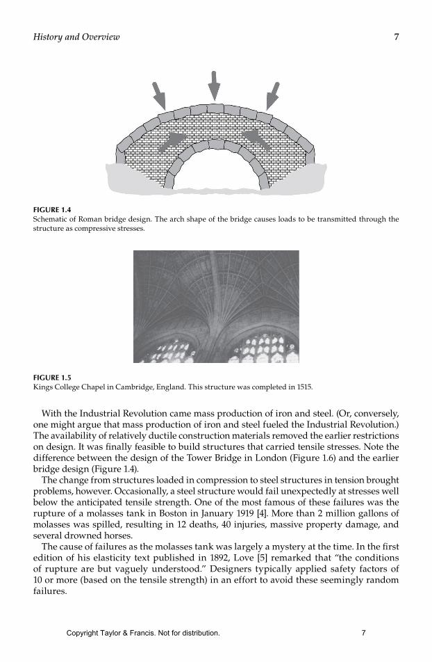
Stone brick and mortar are relatively brittle and are unreliable for carrying tensile loads Consequently pre-Industrial Revolution structures were usually designed to be loaded in compression Figure 14 schematically illustrates a Roman bridge design The arch shape causes compressive rather than tensile stresses to be transmitted through the structure
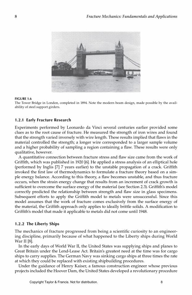
The arch is the predominate shape in pre-Industrial Revolution architecture Windows and roof spans were arched in order to maintain compressive loading For example Figure 15 shows two windows and a portion of the ceiling in Kings College Chapel in Cambridge England Although these shapes are aesthetically pleasing their primary purpose is more pragmatic
Compressively loaded structures are obviously stable since some have lasted for many centuries The pyramids in Egypt are the epitome of a stable design
Copyright Taylor amp Francis Not for distribution 6
7History and Overview
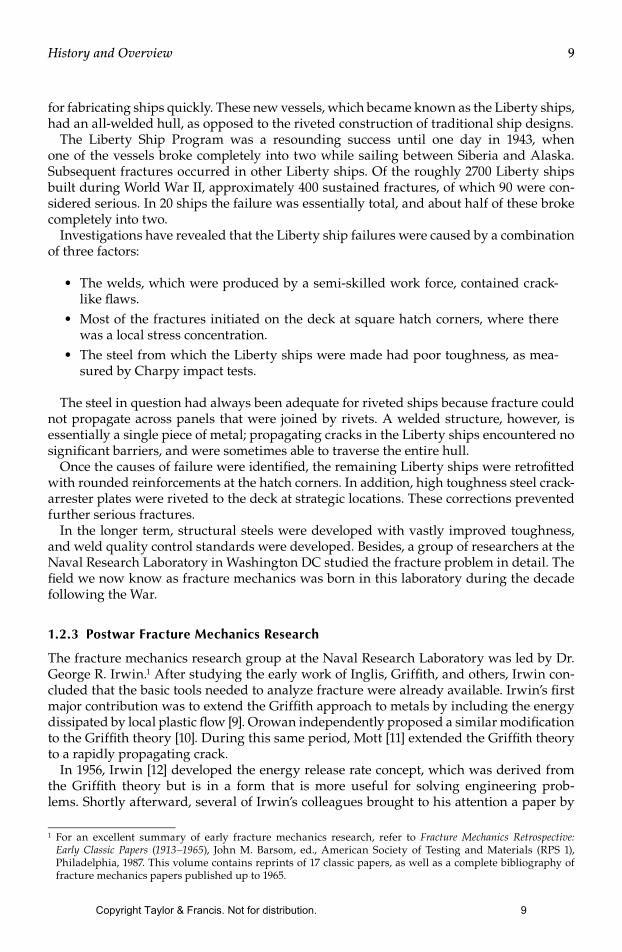
With the Industrial Revolution came mass production of iron and steel (Or conversely one might argue that mass production of iron and steel fueled the Industrial Revolution) The availability of relatively ductile construction materials removed the earlier restrictions on design It was nally feasible to build structures that carried tensile stresses Note the difference between the design of the Tower Bridge in London (Figure 16) and the earlier bridge design (Figure 14)
The change from structures loaded in compression to steel structures in tension brought problems however Occasionally a steel structure would fail unexpectedly at stresses well below the anticipated tensile strength One of the most famous of these failures was the rupture of a molasses tank in Boston in January 1919 [4] More than 2 million gallons of molasses was spilled resulting in 12 deaths 40 injuries massive property damage and several drowned horses
The cause of failures as the molasses tank was largely a mystery at the time In the rst edition of his elasticity text published in 1892 Love [5] remarked that ldquothe conditions of rupture are but vaguely understoodrdquo Designers typically applied safety factors of 10 or more (based on the tensile strength) in an effort to avoid these seemingly random failures
FIGURE 14Schematic of Roman bridge design The arch shape of the bridge causes loads to be transmitted through the structure as compressive stresses
FIGURE 15Kings College Chapel in Cambridge England This structure was completed in 1515
Copyright Taylor amp Francis Not for distribution 7
8 Fracture Mechanics Fundamentals and Applications
121 Early Fracture Research
Experiments performed by Leonardo da Vinci several centuries earlier provided some clues as to the root cause of fracture He measured the strength of iron wires and found that the strength varied inversely with wire length These results implied that aws in the material controlled the strength a longer wire corresponded to a larger sample volume and a higher probability of sampling a region containing a aw These results were only qualitative however
A quantitative connection between fracture stress and aw size came from the work of Grifth which was published in 1920 [6] He applied a stress analysis of an elliptical hole (performed by Inglis [7] 7 years earlier) to the unstable propagation of a crack Grifth invoked the rst law of thermodynamics to formulate a fracture theory based on a sim-ple energy balance According to this theory a aw becomes unstable and thus fracture occurs when the strain energy change that results from an increment of crack growth is sufcient to overcome the surface energy of the material (see Section 23) Grifthrsquos model correctly predicted the relationship between strength and aw size in glass specimens Subsequent efforts to apply the Grifth model to metals were unsuccessful Since this model assumes that the work of fracture comes exclusively from the surface energy of the material the Grifth approach only applies to ideally brittle solids A modication to Grifthrsquos model that made it applicable to metals did not come until 1948
122 The Liberty Ships
The mechanics of fracture progressed from being a scientic curiosity to an engineer-ing discipline primarily because of what happened to the Liberty ships during World War II [8]
In the early days of World War II the United States was supplying ships and planes to Great Britain under the Lend-Lease Act Britainrsquos greatest need at the time was for cargo ships to carry supplies The German Navy was sinking cargo ships at three times the rate at which they could be replaced with existing shipbuilding procedures
Under the guidance of Henry Kaiser a famous construction engineer whose previous projects included the Hoover Dam the United States developed a revolutionary procedure
FIGURE 16The Tower Bridge in London completed in 1894 Note the modern beam design made possible by the avail-ability of steel support girders
Copyright Taylor amp Francis Not for distribution 8
9History and Overview
for fabricating ships quickly These new vessels which became known as the Liberty ships had an all-welded hull as opposed to the riveted construction of traditional ship designs
The Liberty Ship Program was a resounding success until one day in 1943 when one of the vessels broke completely into two while sailing between Siberia and Alaska Subsequent fractures occurred in other Liberty ships Of the roughly 2700 Liberty ships built during World War II approximately 400 sustained fractures of which 90 were con-sidered serious In 20 ships the failure was essentially total and about half of these broke completely into two
Investigations have revealed that the Liberty ship failures were caused by a combination of three factors
bull The welds which were produced by a semi-skilled work force contained crack-like aws
bull Most of the fractures initiated on the deck at square hatch corners where there was a local stress concentration
bull The steel from which the Liberty ships were made had poor toughness as mea-sured by Charpy impact tests
The steel in question had always been adequate for riveted ships because fracture could not propagate across panels that were joined by rivets A welded structure however is essentially a single piece of metal propagating cracks in the Liberty ships encountered no signicant barriers and were sometimes able to traverse the entire hull
Once the causes of failure were identied the remaining Liberty ships were retrotted with rounded reinforcements at the hatch corners In addition high toughness steel crack-arrester plates were riveted to the deck at strategic locations These corrections prevented further serious fractures
In the longer term structural steels were developed with vastly improved toughness and weld quality control standards were developed Besides a group of researchers at the Naval Research Laboratory in Washington DC studied the fracture problem in detail The eld we now know as fracture mechanics was born in this laboratory during the decade following the War
123 Postwar Fracture Mechanics Research
The fracture mechanics research group at the Naval Research Laboratory was led by Dr George R Irwin1 After studying the early work of Inglis Grifth and others Irwin con-cluded that the basic tools needed to analyze fracture were already available Irwinrsquos rst major contribution was to extend the Grifth approach to metals by including the energy dissipated by local plastic ow [9] Orowan independently proposed a similar modication to the Grifth theory [10] During this same period Mott [11] extended the Grifth theory to a rapidly propagating crack
In 1956 Irwin [12] developed the energy release rate concept which was derived from the Grifth theory but is in a form that is more useful for solving engineering prob-lems Shortly afterward several of Irwinrsquos colleagues brought to his attention a paper by
1 For an excellent summary of early fracture mechanics research refer to Fracture Mechanics Retrospective Early Classic Papers (1913ndash1965) John M Barsom ed American Society of Testing and Materials (RPS 1) Philadelphia 1987 This volume contains reprints of 17 classic papers as well as a complete bibliography of fracture mechanics papers published up to 1965
Copyright Taylor amp Francis Not for distribution 9
10 Fracture Mechanics Fundamentals and Applications
Westergaard [13] that was published in 1938 Westergaard had developed a semi-inverse technique for analyzing stresses and displacements ahead of a sharp crack Irwin [14] used the Westergaard approach to show that the stresses and displacements near the crack tip could be described by a single constant that was related to the energy release rate This crack tip characterizing parameter later became known as the stress intensity factor During this same period of time Williams [15] applied a somewhat different technique to derive crack tip solutions that were essentially identical to Irwinrsquos results
A number of successful early applications of fracture mechanics bolstered the standing of this new eld in the engineering community In 1956 Wells [16] used fracture mechan-ics to show that the fuselage failures in several Comet jet aircraft resulted from fatigue cracks reaching a critical size These cracks initiated at windows and were caused by insufcient reinforcement locally combined with square corners which produced a severe stress concentration (Recall the unfortunate hatch design in the Liberty ships) A second early application of fracture mechanics occurred at General Electric in 1957 Winne and Wundt [17] applied Irwinrsquos energy release rate approach to the failure of large rotors from steam turbines They were able to predict the bursting behavior of large disks extracted from rotor forgings and applied this knowledge to the prevention of fracture in actual rotors
It seems that all great ideas encounter stiff opposition initially and fracture mechanics is no exception Although the US military and the electric power generating industry were very supportive of the early work in this eld such was not the case in all provinces of government and industry Several government agencies openly discouraged research in this area
In 1960 Paris and his coworkers [18] failed to nd a receptive audience for their ideas on applying fracture mechanics principles to fatigue crack growth Although Paris et al pro-vided convincing experimental and theoretical arguments for their approach it seems that the design engineers were not yet ready to abandon their SndashN curves in favor of a more rigorous approach to fatigue design The resistance to this work was so intense that Paris and his colleagues were unable to nd a peer-reviewed technical journal that was willing to publish their manuscript They nally opted to publish their work in a University of Washington periodical titled The Trend in Engineering
124 Fracture Mechanics from 1960 through 1980
The World War II obviously separates two distinct eras in the history of fracture mechan-ics There is however some ambiguity as to how the period between the end of the War and the present should be divided One possible historical boundary occurs around 1960 when the fundamentals of linear elastic fracture mechanics (LEFM) were fairly well estab-lished and researchers turned their attention to crack tip plasticity
LEFM ceases to be valid when signicant plastic deformation precedes failure During a relatively short time period (1960ndash1961) several researchers developed analyses to correct for yielding at the crack tip including Irwin [19] Dugdale [20] Barenblatt [21] and Wells [22] The Irwin plastic zone correction [19] was a relatively simple extension of LEFM while Dugdale [20] and Barenblatt [21] each developed somewhat more elaborate models based on a narrow strip of yielded material at the crack tip
Wells [22] proposed the displacement of the crack faces as an alternative fracture crite-rion when signicant plasticity precedes failure Previously Wells had worked with Irwin while on sabbatical at the Naval Research Laboratory When Wells returned to his post at the British Welding Research Association he attempted to apply LEFM to low- and
Copyright Taylor amp Francis Not for distribution 10
11History and Overview
medium-strength structural steels These materials were too ductile for LEFM to apply but Wells noticed that the crack faces moved apart with plastic deformation This obser-vation led to the development of the parameter now known as the crack tip opening dis-placement (CTOD)
In 1968 Rice [23] developed another parameter to characterize nonlinear material behav-ior ahead of a crack By idealizing plastic deformation as nonlinear elastic Rice was able to generalize the energy release rate to nonlinear materials He showed that this nonlin-ear energy release rate can be expressed as a line integral which he called the J integral evaluated along an arbitrary contour around the crack At the time his work was being published Rice discovered that Eshelby [24] had previously published several so-called conservation integrals one of which was equivalent to Ricersquos J integral Eshelby however did not apply his integrals to crack problems
That same year Hutchinson [25] and Rice and Rosengren [26] related the J integral to crack tip stress elds in nonlinear materials These analyses have shown that J can be viewed as a nonlinear stress intensity parameter as well as an energy release rate
Ricersquos work might have been relegated to obscurity had it not been for the active research effort by the nuclear power industry in the United States in the early 1970s Due to legiti-mate concerns for safety as well as due to political and public relations considerations the nuclear power industry endeavored to apply state-of-the-art technology including frac-ture mechanics to the design and construction of nuclear power plants The difculty with applying fracture mechanics in this instance was that most nuclear pressure vessel steels were too tough to be characterized with LEFM without resorting to enormous laboratory specimens In 1971 Begley and Landes [27] who were research engineers at Westinghouse came across Ricersquos article and decided despite skepticism from their coworkers to charac-terize fracture toughness of these steels with the J integral Their experiments were very successful and led to the publication of a standard procedure for J testing of metals 10 years later [28]
Material toughness characterization is only one aspect of fracture mechanics To apply fracture mechanics concepts to design one must have a mathematical relationship between toughness stress and aw size Although these relationships were well established for linear elastic problems a fracture design analysis based on the J integral was not available until Shih and Hutchinson [29] provided the theoretical framework for such an approach in 1976 A few years later the Electric Power Research Institute (EPRI) published a fracture design handbook [30] based on the Shih and Hutchinson methodology
In the United Kingdom Wellrsquos CTOD parameter was applied extensively to fracture analysis of welded structures beginning in the late 1960s While fracture research in the United States was driven primarily by the nuclear power industry during the 1970s frac-ture research in the United Kingdom was motivated largely by the development of oil resources in the North Sea In 1971 Burdekin and Dawes [31] applied several ideas pro-posed by Wells [32] several years earlier and developed the CTOD design curve a semiem-pirical fracture mechanics methodology for welded steel structures The nuclear power industry in the United Kingdom developed their own fracture design analysis [33] based on the strip yield model of Dugdale [20] and Barenblatt [21]
Shih [34] demonstrated a relationship between the J integral and CTOD implying that both parameters are equally valid for characterizing fracture The J-based material testing and structural design approaches developed in the United States and the British CTOD methodology have begun to merge in recent years with positive aspects of each approach combined to yield improved analyses Both parameters are currently applied throughout the world to a range of materials
Copyright Taylor amp Francis Not for distribution 11
12 Fracture Mechanics Fundamentals and Applications
Much of the theoretical foundation of dynamic fracture mechanics was developed in the period between 1960 and 1980 Signicant contributions were made by a number of researchers as discussed in Chapter 4
125 Fracture Mechanics from 1980 to the Present
The eld of fracture mechanics matured in the last two decades of the twentieth century Current research tends to result in incremental advances rather than major gains The application of this technology to practical problems is so pervasive that fracture mechanics is now considered an established engineering discipline
More sophisticated models for material behavior are being incorporated into fracture mechanics analyses While plasticity was the important concern in 1960 more recent work has gone a step further incorporating time-dependent nonlinear material behavior such as viscoplasticity and viscoelasticity The former is motivated by the need for tough creep-resistant high-temperature materials while the latter reects the increasing proportion of plastics in structural applications Fracture mechanics has also been used (and sometimes abused) in the characterization of composite materials
Another trend in recent research is the development of microstuctural models for frac-ture and models to relate local and global fracture behavior of materials A related topic is the efforts to characterize and predict geometry dependence of fracture toughness Such approaches are necessary when traditional so-called single-parameter fracture mechanics breaks down
The continuing explosion in computer technology has aided both the development and application of fracture mechanics technology For example an ordinary desktop computer or laptop is capable of performing complex three-dimensional (3D) nite element analyses of structural components that contain cracks As of this writing nite element analysis is not typically performed with tablet computers and smartphones but that situation will likely change before the next edition of this book is published
Computer technology has also spawned entirely new areas of fracture mechan-ics research Problems encountered in the microelectronics industry have led to active research in interface fracture and nanoscale fracture
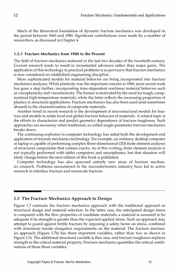
13 The Fracture Mechanics Approach to Design
Figure 17 contrasts the fracture mechanics approach with the traditional approach to structural design and material selection In the latter case the anticipated design stress is compared with the ow properties of candidate materials a material is assumed to be adequate if its strength is greater than the expected applied stress Such an approach may attempt to guard against brittle fracture by imposing a safety factor on stress combined with minimum tensile elongation requirements on the material The fracture mechan-ics approach (Figure 17b) has three important variables rather than two as shown in Figure 17a The additional structural variable is aw size and fracture toughness replaces strength as the critical material property Fracture mechanics quanties the critical combi-nations of these three variables
Copyright Taylor amp Francis Not for distribution 12
13History and Overview
There are two alternative approaches to fracture analysis the energy criterion and the stress intensity approach These two approaches are equivalent in certain circumstances Both are discussed briey below
131 The Energy Criterion
The energy approach states that crack extension (ie fracture) occurs when the energy available for crack growth is sufcient to overcome the resistance of the material The material resistance may include the surface energy plastic work or other type of energy dissipation associated with a propagating crack
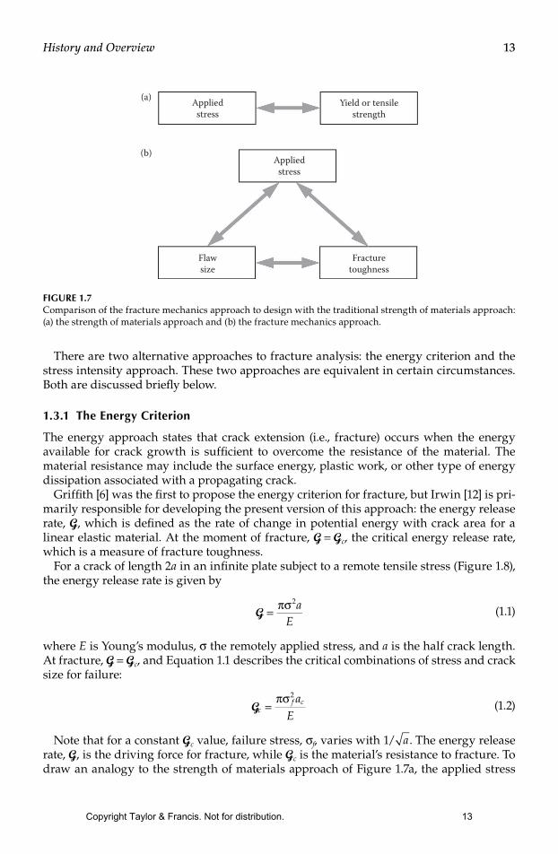
Grifth [6] was the rst to propose the energy criterion for fracture but Irwin [12] is pri-marily responsible for developing the present version of this approach the energy release rate G which is dened as the rate of change in potential energy with crack area for a linear elastic material At the moment of fracture G = Gc the critical energy release rate which is a measure of fracture toughness
For a crack of length 2a in an innite plate subject to a remote tensile stress (Figure 18) the energy release rate is given by
G = πσ2a
E (11)
where E is Youngrsquos modulus σ the remotely applied stress and a is the half crack length At fracture G = Gc and Equation 11 describes the critical combinations of stress and crack size for failure
Gc
f caE
=πσ2
(12)
Note that for a constant Gc value failure stress σf varies with 1 a The energy release rate G is the driving force for fracture while Gc is the materialrsquos resistance to fracture To draw an analogy to the strength of materials approach of Figure 17a the applied stress
Appliedstress
(a)
(b)
Flawsize
Fracturetoughness
Appliedstress
Yield or tensilestrength
FIGURE 17Comparison of the fracture mechanics approach to design with the traditional strength of materials approach (a) the strength of materials approach and (b) the fracture mechanics approach
Copyright Taylor amp Francis Not for distribution 13
14 Fracture Mechanics Fundamentals and Applications
can be viewed as the driving force for plastic deformation while the yield strength is a measure of the materialrsquos resistance to deformation
The tensile stress analogy is also useful for illustrating the concept of similitude A yield strength value measured with a laboratory specimen should be applicable to a large struc-ture yield strength does not depend on specimen size provided the material is reasonably homogeneous One of the fundamental assumptions of fracture mechanics is that fracture toughness (Gc in this case) is independent of the size and geometry of the cracked body a fracture toughness measurement on a laboratory specimen should be applicable to a struc-ture As long as this assumption is valid all conguration effects are taken into account by the driving force G The similitude assumption is valid as long as the material behavior is predominantly linear elastic
132 The Stress Intensity Approach
Figure 19 schematically shows an element near the tip of a crack in an elastic material together with the in-plane stresses on this element Note that each stress component is proportional to a single constant KI If this constant is known the entire stress distribu-tion at the crack tip can be computed with the equations in Figure 19 This constant which is called the stress intensity factor completely characterizes the crack tip conditions in a linear elastic material (The meaning of the subscript on K is explained in Chapter 2) If one assumes that the material fails locally at some critical combination of stress and strain then it follows that fracture must occur at a critical value of stress intensity KIc Thus KIc is an alternate measure of fracture toughness
For the plate illustrated in Figure 18 the stress intensity factor is given by
K aI = σ π (13)
2a
B
σ
FIGURE 18Through-thickness crack in an innite plate subject to a remote tensile stress In practical terms ldquoinniterdquo means that the width of the plate is ≫2a
Copyright Taylor amp Francis Not for distribution 14
15History and Overview
Failure occurs when KI = KIc In this case KI is the driving force for fracture and KIc is a measure of material resistance As with Gc the property of similitude should apply to KIc That is KIc is assumed to be a size-independent material property
Comparing Equations 11 and 13 results in a relationship between KI and G
G = K
EI2
(14)
This same relationship obviously holds for Gc and KIc Thus the energy and stress inten-sity approaches to fracture mechanics are essentially equivalent for linear elastic materials
133 Time-Dependent Crack Growth and Damage Tolerance
Fracture mechanics often plays a role in life prediction of components that are subject to time-dependent crack growth mechanisms such as fatigue or stress corrosion cracking The rate of cracking can be correlated with fracture mechanics parameters such as the stress intensity factor and the critical crack size for failure can be computed if the fracture toughness is known For example the fatigue crack growth rate in metals can usually be described by the following empirical relationship
dadN
C K m= ( )∆ (15)
where dadN is the crack growth per cycle ΔK the stress intensity range and C and m are the material constants
Damage tolerance as its name suggests entails allowing subcritical aws to remain in a structure Repairing awed material or scrapping a awed structure is expensive and is often unnecessary Fracture mechanics provides a rational basis for establishing aw tolerance limits
Consider a aw in a structure that grows with time (eg a fatigue crack or a stress cor-rosion crack) as illustrated schematically in Figure 110 The initial crack size is inferred from nondestructive examination (NDE) and the critical crack size is computed from the applied stress and fracture toughness Normally an allowable aw size would be dened
y
r
Crackx
σyy
τxy
τyx
θ
σxxσ θ θ θ
σ
xxI
yyI
K
K
=
minus
=
2πr 21
232
2πr
cos sin sin
θ θ θ
τ θKxy
I
cos sin sin
cos
21
232
2πr
+
=22 2
32
sin cosθ θ
FIGURE 19Stresses near the tip of a crack in an elastic material
Copyright Taylor amp Francis Not for distribution 15
16 Fracture Mechanics Fundamentals and Applications
by dividing the critical size by a safety factor The predicted service life of the structure can then be inferred by calculating the time required for the aw to grow from its initial size to the maximum allowable size
14 Effect of Material Properties on Fracture
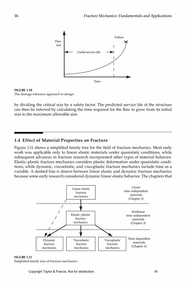
Figure 111 shows a simplied family tree for the eld of fracture mechanics Most early work was applicable only to linear elastic materials under quasistatic conditions while subsequent advances in fracture research incorporated other types of material behavior Elasticndashplastic fracture mechanics considers plastic deformation under quasistatic condi-tions while dynamic viscoelastic and viscoplastic fracture mechanics include time as a variable A dashed line is drawn between linear elastic and dynamic fracture mechanics because some early research considered dynamic linear elastic behavior The chapters that
Flawsize
Failure
Time
Useful service life
FIGURE 110The damage tolerance approach to design
Linear elasticfracture
mechanics
Lineartime-independent
materials(Chapter 2)
Nonlineartime-independent
materials(Chapter 3)
Dynamicfracture
mechanics
Viscoelasticfracture
mechanics
Viscoplasticfracture
mechanics
Time-dependentmaterials
(Chapter 4)
Elasticndashplasticfracture
mechanics
FIGURE 111Simplied family tree of fracture mechanics
Copyright Taylor amp Francis Not for distribution 16
17History and Overview
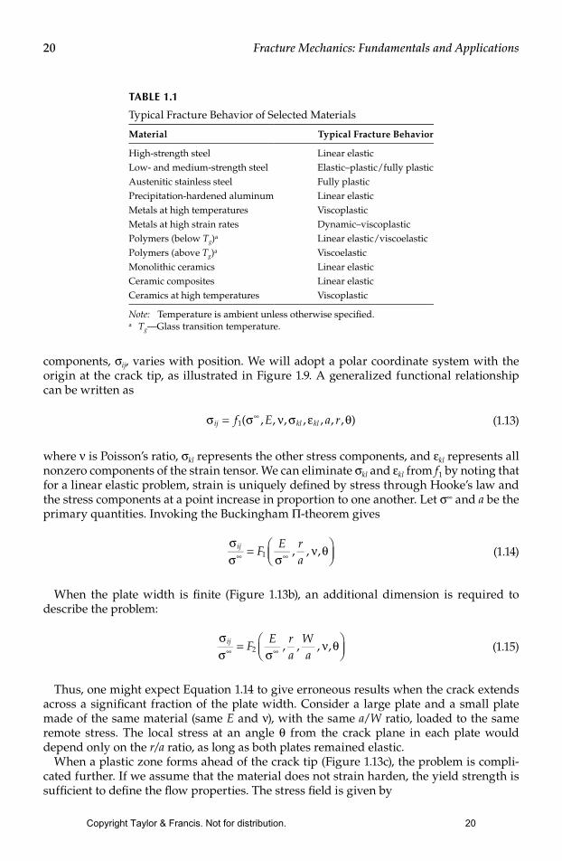
describe the various types of fracture behavior are shown in Figure 111 Elasticndashplastic viscoelastic and viscoplastic fracture behavior are sometimes included in the more gen-eral heading of nonlinear fracture mechanics The branch of fracture mechanics one should apply to a particular problem obviously depends on the material behavior Table 11 lists the typical fracture behavior of various engineering materials
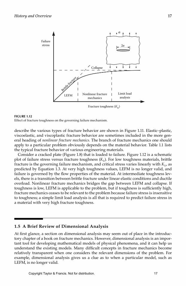
Consider a cracked plate (Figure 18) that is loaded to failure Figure 112 is a schematic plot of failure stress versus fracture toughness (KIc) For low toughness materials brittle fracture is the governing failure mechanism and critical stress varies linearly with KIc as predicted by Equation 13 At very high toughness values LEFM is no longer valid and failure is governed by the ow properties of the material At intermediate toughness lev-els there is a transition between brittle fracture under linear elastic conditions and ductile overload Nonlinear fracture mechanics bridges the gap between LEFM and collapse If toughness is low LEFM is applicable to the problem but if toughness is sufciently high fracture mechanics ceases to be relevant to the problem because failure stress is insensitive to toughness a simple limit load analysis is all that is required to predict failure stress in a material with very high fracture toughness
15 A Brief Review of Dimensional Analysis
At rst glance a section on dimensional analysis may seem out of place in the introduc-tory chapter of a book on fracture mechanics However dimensional analysis is an impor-tant tool for developing mathematical models of physical phenomena and it can help us understand the existing models Many difcult concepts in fracture mechanics become relatively transparent when one considers the relevant dimensions of the problem For example dimensional analysis gives us a clue as to when a particular model such as LEFM is no longer valid
Failurestress
Collapse
2a
σ
LEFMBritt
le frac
ture
Nonlinear fracturemechanics
Limit loadanalysis
Fracture toughness (KIc)
FIGURE 112Effect of fracture toughness on the governing failure mechanism
Copyright Taylor amp Francis Not for distribution 17
18 Fracture Mechanics Fundamentals and Applications
Let us review the fundamental theorem of dimensional analysis and then look at a few simple applications to fracture mechanics
151 The Buckingham Π-Theorem
The rst step in building a mathematical model of a physical phenomenon is to identify all of the parameters that may inuence the phenomenon Assume that a problem or at least an idealized version of it can be described by the following set of scalar quantities u W1 W2 hellip Wn The dimensions of all quantities in this set are denoted by [u] [W1] [W2] hellip [Wn] Now suppose that we wish to express the rst variable u as a function of the remain-ing parameters
u f W W Wn= ( )1 2 hellip (16)
Thus the process of modeling the problem is reduced to nding a mathematical relation-ship that represents f as best as possible We might accomplish this by performing a set of experiments in which we measure u while varying each Wi independently The number of experiments can be greatly reduced and the modeling processes simplied through dimensional analysis The rst step is to identify all of the fundamental dimensional units (fdursquos) in the problem L1 L2 hellip Lm For example a typical mechanics problem may have L1 = length L2 = mass L3 = time We can express the dimensions of each quantity in our problem as the product of powers of the fdursquos that is for any quantity X we have
[ ]X L L La amam= 1 2
1 2 (17)
The quantity X is dimensionless if [X] = 1In the set of Ws we can identify m primary quantities that contain all of the fdursquos in the
problem The remaining variables are secondary quantities and their dimensions can be expressed in terms of the primary quantities
[ ] [ ] [ ] ( )( ) ( )W W W j n mm ja
mam j m j m
+ = = hellip minus+ +1
1 1 2 (18)
Thus we can dene a set of new quantities πi that are dimensionless
πi
m ja
ma
W
W Wm j m j m= +
+ +1
1( ) ( ) (19)
Similarly the dimensions of u can be expressed in terms of the dimensions of the pri-mary quantities
[ ] [ ] [ ]u W Wam
am= 11 (110)
Thus we can form the following dimensionless quantity
π = u
W Wamam
11
(111)
Copyright Taylor amp Francis Not for distribution 18
19History and Overview
According to the Buckingham Π-theorem π depends only on the other dimensionless groups
π π π π= hellip minusF n m( )1 2 (112)
This new function F is independent of the system of measurement units Note that the number of quantities in F has been reduced from the old function by m the number of fdursquos Thus dimensional analysis has reduced the degrees of freedom in our model and we need to vary only n minus m quantities in our experiments or computer simulations
The Buckingham Π-theorem gives guidance on how to scale a problem to different sizes or to other systems of measurement units Each dimensionless group (πi) must be scaled in order to obtain equivalent conditions at two different scales Suppose for example that we wish to perform wind tunnel tests on a model of a new airplane design Dimensional analysis tells us that we should reduce all length dimensions in the same proportion thus we would build a ldquoscalerdquo model of the airplane The length dimensions of the plane are not the only important quantities in the problem however To model the aerodynamic behavior accurately we would need to scale the wind velocity and the viscosity of the air in accordance with the reduced size of the airplane model Modifying the viscosity of air is not practical in most cases In real wind tunnel tests the size of the model is usually close enough to full scale that the errors introduced by the nonscaling viscosity are minor
152 Dimensional Analysis in Fracture Mechanics
Dimensional analysis proves to be a very useful tool in fracture mechanics The later chapters describe how dimensional arguments play a key role in developing mathemati-cal descriptions for important phenomena For now let us explore a few simple examples
Consider a series of cracked plates under a remote tensile stress σinfin as illustrated in Figure 113 Assume that each to be a two-dimensional (2D) problem that is the thickness dimension does not enter into the problem The rst case Figure 113a is an edge crack of length a in an elastic semi-innite plate In this case innite means that the plate width is much larger than the crack size Suppose that we wish to know how one of the stress
a a a
W
(a) (b) (c)
σinfin σinfin σinfin
W
ry
Plasticzone
FIGURE 113Edge-cracked plates subject to a remote tensile stress (a) edge crack in a wide elastic plate (b) edge crack in a nite width elastic plate and (c) edge crack with a plastic zone at the crack tip
Copyright Taylor amp Francis Not for distribution 19
20 Fracture Mechanics Fundamentals and Applications
components σij varies with position We will adopt a polar coordinate system with the origin at the crack tip as illustrated in Figure 19 A generalized functional relationship can be written as
σ σ ν σ ε θij kl klf E a r= infin1( ) (113)
where ν is Poissonrsquos ratio σkl represents the other stress components and εkl represents all nonzero components of the strain tensor We can eliminate σkl and εkl from f1 by noting that for a linear elastic problem strain is uniquely dened by stress through Hookersquos law and the stress components at a point increase in proportion to one another Let σinfin and a be the primary quantities Invoking the Buckingham Π-theorem gives
σσ σ
ν θij FE r
ainfin infin=
1
(114)
When the plate width is nite (Figure 113b) an additional dimension is required to describe the problem
σσ σ
ν θij FE r
aWainfin infin=
2
(115)
Thus one might expect Equation 114 to give erroneous results when the crack extends across a signicant fraction of the plate width Consider a large plate and a small plate made of the same material (same E and ν) with the same aW ratio loaded to the same remote stress The local stress at an angle θ from the crack plane in each plate would depend only on the ra ratio as long as both plates remained elastic
When a plastic zone forms ahead of the crack tip (Figure 113c) the problem is compli-cated further If we assume that the material does not strain harden the yield strength is sufcient to dene the ow properties The stress eld is given by
TABLE 11
Typical Fracture Behavior of Selected Materials
Material Typical Fracture Behavior
High-strength steel Linear elasticLow- and medium-strength steel Elasticndashplasticfully plasticAustenitic stainless steel Fully plasticPrecipitation-hardened aluminum Linear elasticMetals at high temperatures ViscoplasticMetals at high strain rates DynamicndashviscoplasticPolymers (below Tg)a Linear elasticviscoelasticPolymers (above Tg)a ViscoelasticMonolithic ceramics Linear elasticCeramic composites Linear elasticCeramics at high temperatures Viscoplastic
Note Temperature is ambient unless otherwise specieda TgmdashGlass transition temperature
Copyright Taylor amp Francis Not for distribution 20
21History and Overview
σσ σ
σσ
ν θij YS yFE r
aWa
ra
=
3 (116)
The rst two functions F1 and F2 correspond to LEFM while F3 is an elasticndashplastic relationship Thus dimensional analysis tells us that LEFM is valid only when ry ≪ a and σinfin ≪ σYS In Chapter 2 the same conclusion is reached through a somewhat more compli-cated argument
References
1 Duga JJ Fisher WH Buxbaum RW Roseneld AR Burh AR Honton EJ and McMillan SC The Economic Effects of Fracture in the United States NBS Special Publication 647-2 United States Department of Commerce Washington DC March 1983
2 Jones RE and Bradley WL Failure analysis of a polyethylene natural gas pipeline Forensic Engineering 1 1987 47ndash59
3 Jones RE and Bradley WL Fracture Toughness Testing of Polyethylene Pipe Materials ASTM STP 995 Vol 1 American Society for Testing and Materials Philadelphia pp 447ndash456 1989
4 Shank ME A critical review of brittle failure in carbon plate steel structures other than ships Ship Structure Committee Report SSC-65 National Academy of Science-National Research Council Washington DC December 1953
5 Love AEH A Treatise on the Mathematical Theory of Elasticity Dover Publications New York 1944
6 Grifth AA The phenomena of rupture and ow in solids Philosophical Transactions Series A 221 1920 163ndash198
7 Inglis CE Stresses in a plate due to the presence of cracks and sharp corners Transactions of the Institute of Naval Architects 55 1913 219ndash241
8 Bannerman DB and Young RT Some improvements resulting from studies of welded ship failures Welding Journal 25 1946 223ndash236
9 Irwin GR Fracture dynamics Fracturing of Metals American Society for Metals Cleveland pp 147ndash166 1948
10 Orowan E Fracture and strength of solids Reports on Progress in Physics XII 1948 185ndash232 11 Mott NF Fracture of metals Theoretical considerations Engineering 165 1948 16ndash18 12 Irwin GR Onset of fast crack propagation in high strength steel and aluminum alloys
Sagamore Research Conference Proceedings 2 1956 289ndash305 13 Westergaard HM Bearing pressures and cracks Journal of Applied Mechanics 6 1939 49ndash53 14 Irwin GR Analysis of stresses and strains near the end of a crack traversing a plate Journal
of Applied Mechanics 24 1957 361ndash364 15 Williams ML On the stress distribution at the base of a stationary crack Journal of Applied
Mechanics 24 1957 109ndash114 16 Wells AA The condition of fast fracture in aluminum alloys with particular reference to
comet failures British Welding Research Association Report April 1955 17 Winne DH and Wundt BM Application of the Grifth-Irwin theory of crack propagation to
the bursting behavior of disks including analytical and experimental studies Transactions of the American Society of Mechanical Engineers 80 1958 1643ndash1655
18 Paris PC Gomez MP and Anderson WP A rational analytic theory of fatigue The Trend in Engineering 13 1961 9ndash14
19 Irwin GR Plastic zone near a crack and fracture toughness Sagamore Research Conference Proceedings Vol 4 Syracuse University Research Institute Syracuse NY pp 63ndash78 1961
Copyright Taylor amp Francis Not for distribution 21
22 Fracture Mechanics Fundamentals and Applications
20 Dugdale DS Yielding in steel sheets containing slits Journal of the Mechanics and Physics of Solids 8 1960 100ndash104
21 Barenblatt GI The mathematical theory of equilibrium cracks in brittle fracture Advances in Applied Mechanics Vol VII Academic Press New York pp 55ndash129 1962
22 Wells AA Unstable crack propagation in metals Cleavage and fast fracture Proceedings of the Crack Propagation Symposium Vol 1 Paper 84 Craneld UK 1961
23 Rice JR A path independent integral and the approximate analysis of strain concentration by notches and cracks Journal of Applied Mechanics 35 1968 379ndash386
24 Eshelby JD The continuum theory of lattice defects Solid State Physics 3 1956 79ndash144 25 Hutchinson JW Singular behavior at the end of a tensile crack tip in a hardening material
Journal of the Mechanics and Physics of Solids 16 1968 13ndash31 26 Rice JR and Rosengren GF Plane strain deformation near a crack tip in a power-law hard-
ening material Journal of the Mechanics and Physics of Solids 16 1968 1ndash12 27 Begley J A and Landes JD The J-Integral as a Fracture Criterion ASTM STP 514 American
Society for Testing and Materials Philadelphia pp 1ndash20 1972 28 E 813-81 Standard Test Method for JIc a Measure of Fracture Toughness American Society for
Testing and Materials Philadelphia 1981 29 Shih CF and Hutchinson JW Fully plastic solutions and large-scale yielding estimates for
plane stress crack problems Journal of Engineering Materials and Technology 98 1976 289ndash295 30 Kumar V German MD and Shih CF An engineering approach for elastic-plastic fracture
analysis EPRI Report NP-1931 Electric Power Research Institute Palo Alto CA 1981 31 Burdekin FM and Dawes MG Practical use of linear elastic and yielding fracture mechanics
with particular reference to pressure vessels Proceedings of the Institute of Mechanical Engineers Conference London pp 28ndash37 May 1971
32 Wells AA Application of fracture mechanics at and beyond general yielding British Welding Journal 10 1963 563ndash570
33 Harrison RP Loosemore K Milne I and Dowling AR Assessment of the integrity of structures containing defects Central Electricity Generating Board Report RHR6-Rev 2 April 1980
34 Shih CF Relationship between the J-integral and the crack opening displacement for station-ary and extending cracks Journal of the Mechanics and Physics of Solids 29 1981 305ndash326
Copyright Taylor amp Francis Not for distribution 22
Chapter 1
Units associated with basicelectrical quantities
At the end of this chapter you should be able to
bull state the basic SI units
bull recognize derived SI units
bull understand prefixes denoting multiplication and division
bull state the units of charge force work and power and perform simple calculations involving these units
bull state the units of electrical potential emf resistance conductance power and energy and perform simplecalculations involving these units
11 SI units
The system of units used in engineering and science isthe Systegraveme Internationale drsquoUniteacutes (International sys-tem of units) usually abbreviated to SI units and isbased on the metric system This was introduced in 1960and is now adopted by the majority of countries as theofficial system of measurement
The basic units in the SI system are listed with theirsymbol s i n Tabl e 11
Derived SI units use combinations of basic units andthere are many of them Two examples are
bull Velocity mdash metres per second (ms)
bull Acceleration mdash metres per second squared (ms2)
SI units may be made larger or smaller by using prefixeswhich denote multiplication or division by a particu-lar amount The six most common multiples with theirmeaning are listed in Table 12 For a more completel i st of prefixes see page 4
Table 11 Basic SI Units
Quantity Unit
length metre m
mass kilogram kg
time second s
electric current ampere A
thermodynamic temperature kelvin K
luminous intensity candela cd
amount of substance mole mol
12 Charge
The unit of charge is the coulomb (C) whereone coulomb is one ampere second (1 coulomb =624times1018 electrons) The coulomb is defined as thequantity of electricity which flows past a given point
DOI 101016B978-1-85617-770-200001-X
Copyright Taylor amp Francis Not for distribution 23
Part
1
4 Electrical Circuit Theory and Technology
Table 12
Prefix Name Meaning
M mega multiply by 1 000 000 (ie times106)
k kilo multiply by 1000 (ie times103)
m milli divide by 1000 (ie times10minus3)
micro micro divide by 1 000 000 (ie times10minus6)
n nano divide by 1 000 000 000 (ie times10minus9)
p pico divide by 1 000 000 000 000 (ie times10minus12)
in an electric circuit when a current of one ampere ismaintained for one second Thus
charge in coulombs Q=It
where I is the current in amperes and t is the time inseconds
Problem 1 If a current of 5 A flows for 2minutes find the quantity of electricity transferred
Quantity of electricity Q = It coulombs
I =5 A t =2times60=120 s
Hence Q =5times120=600 C
13 Force
The unit of force is the newton (N) where one newtonis one kilogram metre per second squared The newtonis defined as the force which when applied to a mass ofone kilogram gives it an acceleration of one metre persecond squared Thus
force in newtons F=ma
where m is the mass in kilograms and a is the accelera-tion in metres per second squared Gravitational forceor weight is mg where g =981 ms2
Problem 2 A mass of 5000 g is accelerated at2 ms2 by a force Determine the force needed
Force=masstimesacceleration
=5 kgtimes2 ms2 =10kg m
s2 =10 N
Problem 3 Find the force acting verticallydownwards on a mass of 200 g attached to a wire
Mass=200 g=02 kg and acceleration due to gravityg =981 ms2
Force acting downwards=weight=masstimesacceleration
=02 kgtimes981 ms2
=1962 N
14 Work
The unit of work or energy is the joule (J) where onejoule is one newton metre The joule is defined as thework done or energy transferred when a force of onenewton is exerted through a distance of one metre in thedirection of the force Thus
work done on a body in joules W =Fs
where F is the force in newtons and s is the distance inmetres moved by the body in the direction of the forceEnergy is the capacity for doing work
15 Power
The unit of power is the watt (W) where one watt is onejoule per second Power is defined as the rate of doingwork or transferring energy Thus
power in watts P= Wt
where W is the work done or energy transferred in joulesand t is the time in seconds Thus
energy in joules W =Pt
Copyright Taylor amp Francis Not for distribution 24
Part
1
Units associated with basic electrical quantities 5
Problem 4 A portable machine requires a forceof 200 N to move it How much work is done if themachine is moved 20 m and what average power isutilized if the movement takes 25 s
Work done = force times distance = 200 N times 20 m
= 4000 Nm or 4 kJ
Power = work done
time taken= 4000 J
25 s= 160 Js=160 W
Problem 5 A mass of 1000 kg is raised through aheight of 10 m in 20 s What is (a) the work doneand (b) the power developed
(a) Work done=forcetimesdistance and
force=masstimesacceleration
Hence work done= (1000 kgtimes981 ms2)times (10 m)
=98 100 Nm
=981 kNm or 981 kJ
(b) Power= work done
time taken= 98 100 J
20 s= 4905 Js
=4905 W or 4905 kW
Now try the following exercise
Exercise 1 Further problems on unitsassociated with basic electricalquantities
(Take g=981 ms2 where appropriate)
1 What force is required to give a mass of 20 kgan acceleration of 30 ms2 [600 N]
2 Find the accelerating force when a car havinga mass of 17 Mg increases its speed with aconstant acceleration of 3 ms2 [51 kN]
3 A force of 40 N accelerates a mass at 5 ms2Determine the mass [8 kg]
4 Determine the force acting downwardson a mass of 1500 g suspended on astring [1472 N]
5 A force of 4 N moves an object 200 cm in thedirection of the force What amount of workis done [8 J]
6 A force of 25 kN is required to lift a loadHow much work is done if the load is liftedthrough 500 cm [125 kJ]
7 An electromagnet exerts a force of 12 N andmoves a soft iron armature through a dis-tance of 15 cm in 40 ms Find the powerconsumed [45 W]
8 A mass of 500 kg is raised to a height of 6 min 30 s Find (a) the work done and (b) thepower developed
[(a) 2943 kNm (b) 981 W]
9 What quantity of electricity is carried by624times1021 electrons [1000 C]
10 In what time would a current of 1 A transfera charge of 30 C [30 s]
11 A current of 3 A flows for 5 minutes Whatcharge is transferred [900 C]
12 How long must a current of 01 A flow so asto transfer a charge of 30 C [5 minutes]
13 Rewrite the following as indicated(a) 1000 pF= nF(b) 002microF= pF(c) 5000 kHz= MHz(d) 47 k= M(e) 032 mA= microA
[(a) 1 nF (b) 20 000 pF (c) 5 MHz(d) 0047 M (e) 320microA]
16 Electrical potential and emf
The unit of electric potential is the volt (V) where onevolt is one joule per coulomb One volt is defined as thedifference in potential between two points in a conductorwhich when carrying a current of one ampere dissipatesa power of one watt ie
volts = watts
amperes= joulessecond
amperes
= joules
ampere seconds= joules
coulombs
A change in electric potential between two points inan electric circuit is called a potential difference Theelectromotive force (emf) provided by a source ofenergy such as a battery or a generator is measured involts
Copyright Taylor amp Francis Not for distribution 25
Part
1
6 Electrical Circuit Theory and Technology
17 Resistance and conductance
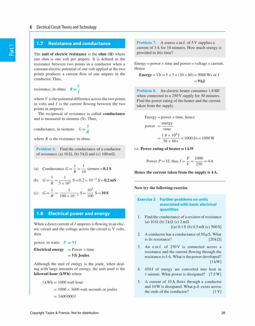
The unit of electric resistance is the ohm () whereone ohm is one volt per ampere It is defined as theresistance between two points in a conductor when aconstant electric potential of one volt applied at the twopoints produces a current flow of one ampere in theconductor Thus
resistance in ohms R= VI
where V is the potential difference across the two pointsin volts and I is the current flowing between the twopoints in amperes
The reciprocal of resistance is called conductanceand is measured in siemens (S) Thus
conductance in siemens G= 1R
where R is the resistance in ohms
Problem 6 Find the conductance of a conductorof resistance (a) 10 (b) 5 k and (c) 100 m
(a) Conductance G = 1
R= 1
10siemen=01 S
(b) G = 1
R= 1
5times103S=02times10minus3 S=02 mS
(c) G = 1
R= 1
100times10minus3 S= 103
100S=10 S
18 Electrical power and energy
When a direct current of I amperes is flowing in an elec-tric circuit and the voltage across the circuit is V voltsthen
power in watts P = VI
Electrical energy = Power times time
= VIt Joules
Although the unit of energy is the joule when deal-ing with large amounts of energy the unit used is thekilowatt hour (kWh) where
1 kWh = 1000 watt hour
= 1000 times 3600 watt seconds or joules
= 3 600 000 J
Problem 7 A source emf of 5 V supplies acurrent of 3 A for 10 minutes How much energy isprovided in this time
Energy=powertimes time and power=voltagetimescurrentHence
Energy=VIt =5times3times (10times60)=9000 Ws or J
=9 kJ
Problem 8 An electric heater consumes 18 MJwhen connected to a 250 V supply for 30 minutesFind the power rating of the heater and the currenttaken from the supply
Energy =powertimes time hence
power = energy
time
= 18 times 106 J
30 times 60 s=1000 Js=1000 W
ie Power rating of heater=1 kW
Power P =VI thus I = P
V= 1000
250=4 A
Hence the current taken from the supply is 4 A
Now try the following exercise
Exercise 2 Further problems on unitsassociated with basic electricalquantities
1 Find the conductance of a resistor of resistance(a) 10 (b) 2 k (c) 2 m
[(a) 01 S (b) 05 mS (c) 500 S]
2 A conductor has a conductance of 50microS Whatis its resistance [20 k]
3 An emf of 250 V is connected across aresistance and the current flowing through theresistance is 4 A What is the power developed
[1 kW]
4 450 J of energy are converted into heat in1 minute What power is dissipated [75 W]
5 A current of 10 A flows through a conductorand 10 W is dissipated What pd exists acrossthe ends of the conductor [1 V]
Copyright Taylor amp Francis Not for distribution 26
Part
1
Units associated with basic electrical quantities 7
6 A battery of emf 12 V supplies a currentof 5 A for 2 minutes How much energy issupplied in this time [72 kJ]
7 A dc electric motor consumes 36 MJ when con-nected to a 250 V supply for 1 hour Find thepower rating of the motor and the current takenfrom the supply [10 kW 40 A]
19 Summary of terms units andtheir symbols
Quantity Quantity Unit UnitSymbol Symbol
Length l metre m
Mass m kilogram kg
Time t second s
Velocity v metres per ms orsecond msminus1
Acceleration a metres per ms2 orsecond msminus2
squared
Force F newton N
Electrical Q coulomb Ccharge orquantity
Electric current I ampere A
Resistance R ohm
Conductance G siemen S
Electromotive E volt Vforce
Potential V volt Vdifference
Work W joule J
Energy E (or W) joule J
Power P watt W
As progress is made through Electrical Circuit Theoryand Technology many more terms will be met A fulllist of electrical quantities together with their symbolsand uni t s are given i n Part 4 page 725
Copyright Taylor amp Francis Not for distribution 27
C H A P T E R
EAL Unit Elec201
Learning outcomes
When you have completed this chapter you should1 Understand how health and safety applies to electrotechnical
operations
2 Understand health and safety procedures in the work environment
3 Understand the basic electrical safety requirements
4 Know the safety requirements for using access equipment
5 Understand the importance of establishing a safe working environment (i)
6 Understand the importance of establishing a safe working environment (ii)
Health and safety in electrical installation
1
EA
L E
lect
rica
l Ins
talla
tio
n W
ork
ndash L
evel
2 9
78 1
138
917
14 9
copy 2
016
Lins
ley
Pub
lishe
d b
y Ta
ylor
amp F
ranc
is A
ll rig
hts
rese
rved
Copyright Taylor amp Francis Not for distribution 28
2 1 EAL Electrical Installation Work Level 2
Introduction
Understanding how health and safety is legislated and put into practice is essential for anyone operating within the electrical installation industry Defi ning how statutory regulation ties in with non-statutory codes of practice such as application of wiring regulations is essential as is understanding the roles and responsibilities within health and safety These range from employers to the Health and Safety Executive (HSE) and from employees to safety representatives all with a common aim to learn and inform so that such events are not repeated
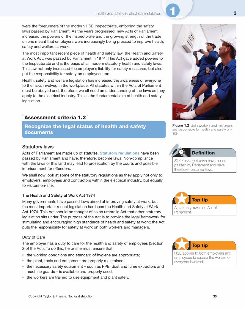
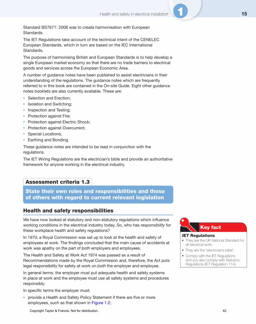
Understanding how reduced electrical systems bring about a reduction in electric shocks is paramount in essence the likelihood of being exposed to live parts is lessened Such measures are complemented through a regime that inspects and tests all electrical equipment and ensures that all work is made safe through incorporating safe isolation procedures Safety is also applied when using access equipment so that the user can choose the most appropriate equipment through current Prefabricated Access Suppliersrsquo and Manufacturersrsquo Association (PASMA) requirements Understanding how employers implement a safe system of work is fundamental in instigating risk assessments in order to recognize hazards control through permit-to-work systems and defi ne operations through method statements which signpost exactly how a task is to be implemented It is essential to understand that personal protective equipment (PPE) only lessens the effects of accidents and does not eliminate them and is only necessary when hazards cannot be eliminated The exposure to hazards could also be minimized if less hazardous substances are used the hazard is enclosed or employees are fully trained with only authorized personnel permitted to operate certain hazardous environments and equipment in particular when asbestos is involved The use of signage fi re-fi ghting equipment and training also ensure measures are in place to deal with situations during emergencies
Assessment criteria 11
State the general aims of health and safety legislation
Safety regulations and laws
At the beginning of the nineteenth century children formed a large part of the working population of Great Britain They started work early in their lives and they worked long hours for unscrupulous employers or masters
The Health and Morals of Apprentices Act of 1802 was introduced by Robert Peel in an attempt to reduce apprentice working hours to 12 hours per day and to improve the conditions of their employment The Factories Act of 1833 restricted the working week for children aged 13ndash18 years to 69 hours in any working week
With the introduction of the Factories Act of 1833 the fi rst four full-time Factory Inspectors were appointed They were allowed to employ a small number of assistants and were given the responsibility of inspecting factories throughout England Scotland Ireland and Wales This small overworked band of men
Figure 11 Wearing PPE lessens the impact of accidents but does not eliminate them
Copyright Taylor amp Francis Not for distribution 29
3Health and safety in electrical installationHealth and safety in electrical installation 1were the forerunners of the modern HSE Inspectorate enforcing the safety laws passed by Parliament As the years progressed new Acts of Parliament increased the powers of the Inspectorate and the growing strength of the trade unions meant that employers were increasingly being pressed to improve health safety and welfare at work
The most important recent piece of health and safety law the Health and Safety at Work Act was passed by Parliament in 1974 This Act gave added powers to the Inspectorate and is the basis of all modern statutory health and safety laws This law not only increased the employerrsquos liability for safety measures but also put the responsibility for safety on employees too
Health safety and welfare legislation has increased the awareness of everyone to the risks involved in the workplace All statutes within the Acts of Parliament must be obeyed and therefore we all need an understanding of the laws as they apply to the electrical industry This is the fundamental aim of health and safety legislation
Assessment criteria 12
Recognize the legal status of health and safety documents
Statutory lawsActs of Parliament are made up of statutes Statutory regulations have been passed by Parliament and have therefore become laws Non-compliance with the laws of this land may lead to prosecution by the courts and possible imprisonment for offenders
We shall now look at some of the statutory regulations as they apply not only to employers employees and contractors within the electrical industry but equally to visitors on-site
The Health and Safety at Work Act 1974
Many governments have passed laws aimed at improving safety at work but the most important recent legislation has been the Health and Safety at Work Act 1974 This Act should be thought of as an umbrella Act that other statutory legislation sits under The purpose of the Act is to provide the legal framework for stimulating and encouraging high standards of health and safety at work the Act puts the responsibility for safety at work on both workers and managers
Duty of Care
The employer has a duty to care for the health and safety of employees (Section 2 of the Act) To do this he or she must ensure that
l the working conditions and standard of hygiene are appropriatel the plant tools and equipment are properly maintainedl the necessary safety equipment ndash such as PPE dust and fume extractors and
machine guards ndash is available and properly usedl the workers are trained to use equipment and plant safely
Defi nition
Statutory regulations have been passed by Parliament and have therefore become laws
Top tip
A statutory law is an Act of Parliament
Top tip
HSE applies to both employers and employees to secure the welfare of everyone involved
Figure 12 Both workers and managers are responsible for health and safety on-site
Copyright Taylor amp Francis Not for distribution 30
4 1 EAL Electrical Installation Work Level 2
Failure to comply with the Health and Safety at Work Act is a criminal offence and any infringement of the law can result in heavy fi nes a prison sentence or both This would apply to an employer who could be prosecuted if knowingly allowing an employee to work and that employee then places other people at risk or possible injury
Employees have a duty to care for their own health and safety and that of others who may be affected by their actions including fellow employees and members of the public (Section 7 of the Act) To do this they must
l take reasonable care to avoid injury to themselves or others as a result of their work activity
l co-operate with their employer helping him or her to comply with the requirements of the Act
l not interfere with or misuse anything provided to protect their health and safety
The Electricity at Work Regulations 1989 (EWR)
This legislation came into force in 1990 and replaced earlier regulations such as the Electricity (Factories Act) Special Regulations 1944 The regulations are made under the Health and Safety at Work Act 1974 and enforced by the Health and Safety Executive The purpose of the regulations is to lsquorequire precautions to be taken against the risk of death or personal injury from electricity in work activitiesrsquo
Section 4 of the EWR tells us that lsquoall systems must be constructed so as to prevent danger hellip and be properly maintained hellip Every work activity shall be carried out in a manner which does not give rise to danger hellip In the case of work of an electrical nature it is preferable that the conductors be made dead before work commencesrsquo
The EWR do not tell us specifi cally how to carry out our work activities but they can be used in a court of law as evidence to claim compliance with other statutory requirements If proceedings were brought against an individual for breaking the EWR the only acceptable defence would be lsquoto prove that all reasonable steps were taken and all diligence exercised to avoid the offencersquo (Regulation 29)
An electrical contractor could reasonably be expected to have lsquoexercised all diligencersquo if the installation was wired according to the IET Wiring Regulations (see below) However electrical contractors must become more lsquolegally awarersquo following the conviction of an electrician for manslaughter at Maidstone Crown Court in 1989 The court accepted that an electrician had caused the death of another man as a result of his shoddy work in wiring up a central heating system He received a nine-month suspended prison sentence This case has set an important legal precedent and in future any tradesman or professional who causes death through negligence or poor workmanship risks prosecution and possible imprisonment
The EWR is split into 16 regulations of its own These regulations apply to any person who is engaged with electrical work employers the self-employed and employees including apprentices
Copyright Taylor amp Francis Not for distribution 31
5Health and safety in electrical installationHealth and safety in electrical installation 1
Regulation 1 Citation and commencement
The fi rst regulation puts the EWR into context and cites that the EWR came into force on 1 April 1990
Regulation 2 Interpretation
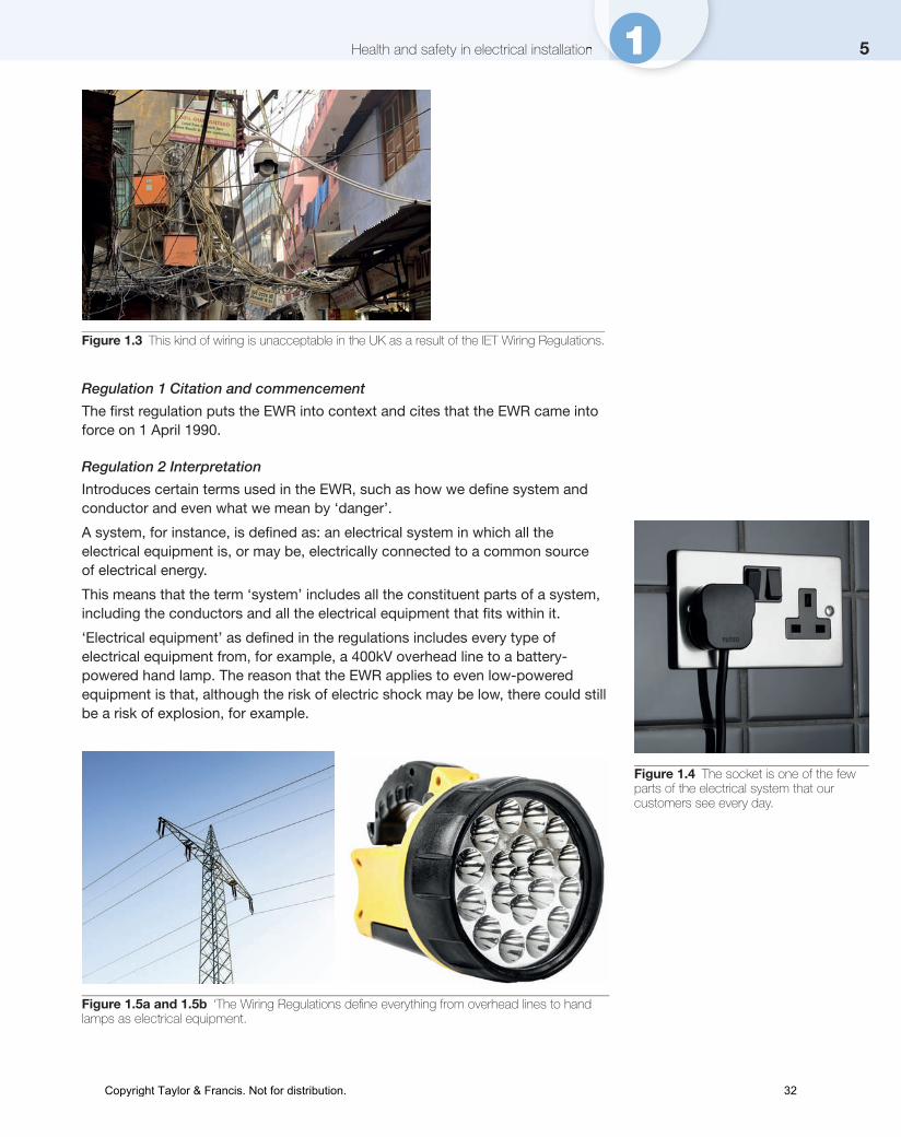
Introduces certain terms used in the EWR such as how we defi ne system and conductor and even what we mean by lsquodangerrsquo
A system for instance is defi ned as an electrical system in which all the electrical equipment is or may be electrically connected to a common source of electrical energy
This means that the term lsquosystemrsquo includes all the constituent parts of a system including the conductors and all the electrical equipment that fi ts within it
lsquoElectrical equipmentrsquo as defi ned in the regulations includes every type of electrical equipment from for example a 400kV overhead line to a battery-powered hand lamp The reason that the EWR applies to even low-powered equipment is that although the risk of electric shock may be low there could still be a risk of explosion for example
Figure 13 This kind of wiring is unacceptable in the UK as a result of the IET Wiring Regulations
Figure 14 The socket is one of the few parts of the electrical system that our customers see every day
Figure 15a and 15b lsquoThe Wiring Regulations defi ne everything from overhead lines to hand lamps as electrical equipment
Copyright Taylor amp Francis Not for distribution 32
6 1 EAL Electrical Installation Work Level 2
A very important distinction is made regarding the terms lsquochargedrsquo and lsquoliversquo This is because when electricians carry out safe isolation procedures they must ensure that all forms of energy are removed from a circuit including any batteries or other devices such as capacitors that can store charge
Consequently the term lsquodeadrsquo means a conductor that is not lsquoliversquo or lsquochargedrsquo
Regulation 3 Persons on whom duties are imposed by these Regulations
This regulation gives a clear statement of who the EWR applies to and makes a statement
It shall be the duty of every employee while at work to comply with the provisions of these regulations in so far as they relate to matters which are within hisher control
This means that trainee electricians although not fully qualifi ed must adhere to the EWR as well as always cooperating with their employer The EWR also applies to non-technical personnel such as offi ce workers for instance who must realize what they can or cannot do regarding electrical equipment and the importance of not interfering with safety equipment
The EWR also defi nes the distinction between the terms lsquoabsolutersquo and lsquoreasonably practicablersquo lsquoAbsolutersquo means that something must be met irrespective of time or cost While lsquoreasonably practicablersquo means that a duty holder must decide the extent of the risks involved with the job in question against the costs involved as well as the actual diffi culty in implementing safety measures
Regulation 4 Systems work activities and protective equipment
lsquoSystemrsquo has already been defi ned above but this regulation ensures that systems are designed so far as is reasonably practicable to not pose a danger to anybody This includes scheduling maintenance activities so that the equipment selected for any system is fi t for purpose
Regulation 5 Strength and capability of electrical equipment
This regulation ensures that the system and all related equipment can withstand certain electromechanicalchemical stresses and temperature rise during normal operation overload conditions and even fault current
Regulation 6 Adverse or hazardous environments
The regulation draws attention to the kinds of adverse conditions where danger could arise if equipment is not designed properly or fi t for purpose These sorts of considerations include impact damage weather conditions temperature and even explosive conditions such as dust-rich environments
Regulation 7 Insulation protection and placing of conductors
This regulation looks at the danger surrounding electric shock and is concerned with insulating conductors or placing andor shielding them so that people cannot touch them directly and receive an electric shock or burn
Regulation 8 Earthing or other suitable precautions
This regulation looks at how systems are protected to ensure that danger and specifi cally electric shock is minimized if faults occur Both basic and fault protection measures apply including earthing bonding separation and insulation of live partsCopyright Taylor amp Francis Not for distribution 33
7Health and safety in electrical installationHealth and safety in electrical installation 1
Regulation 9 Integrity of referenced conductors
The object of this regulation is to prevent certain conductors that are designed for electrical safety from being altered or to impose restrictions in their use to stop dangerous situations arising This is because any interference or fault in combined conductors can lead to possibly high dangerous voltages being developed across parts that are not normally live therefore bringing about danger of electric shock
Regulation 10 Connections
The object of this regulation is to defi ne the requirement regarding joints and connections It specifi es that all electrical connections need to be both mechanically and electrically strong as well as being suitable for use In essence all electrical connections need to be low in resistance but a problem occurs when joints are not formed properly because they create high resistance joints which in turn creates areas where power is not normally dissipated and electrical fi res are created
Regulation 11 Means for protecting from excess of current
The object of this regulation is the requirement to include protective devices to interrupt the supply when excess current is drawn This is normally provided through fuses and circuit breakers as well as additional protection through residual current devices (RCDs)
Figure 16 Insulators provide protection from high voltages but in this instance the electricity will be turned off to ensure safety
Figure 17 Residual current devices add additional protection against excess currentCopyright Taylor amp Francis Not for distribution 34
8 1 EAL Electrical Installation Work Level 2
Regulation 12 Means for cutting off the supply and for isolation
The object of this regulation is to install where necessary a suitable means of electrical isolation For instance if the control equipment of an electrical motor is in a different room to the motor then the control equipment must be encased in a lockable enclosure
It is worth noting that lsquoisolationrsquo means that all forms of energy are removed from a circuit including any batteries or other devices such as capacitors that can store charge
Regulation 13 Precautions for work on equipment made dead
This regulation ensures that adequate precautions shall be taken to prevent electrical equipment which has been made dead from becoming live when work is carried out on or near that equipment Essentially what this regulation is proposing is that electricians always carry out a safe isolation procedure The regulation also informs that where reasonable a written procedure known as a permit-to-work should be used to authorize and control electrical maintenance
Regulation 14 Work on or near live conductors
This regulation ensures that no person shall be engaged in any work activity on or so near any live conductor (other than one suitably covered with insulating material so as to prevent danger) that danger may arise unless
a it is unreasonable in all the circumstances for it to be dead andb it is reasonable in all the circumstances for the person to be at work on or
near it while it is live andc suitable precautions (including where necessary the provision of suitable
protective equipment) are taken to prevent injury
In other words there is an expectation that electricians only work on dead supplies unless there is a reason against it and you can justify that reason
The regulation also specifi es that the test instrument used to establish that a circuit is dead must be fi t for purpose or lsquoapprovedrsquo It also mentions procedures regarding working in and around overhead power lines as well as quoting the Health and Safety at Work Act 1974 with regard to the provision of suitably trained fi rst-aiders in the workplace
Regulation 15 Working space access and lighting
This regulations ensures that for the purposes of preventing injury adequate working space adequate means of access and adequate lighting shall be provided when working with electrical equipment For instance when live conductors are in the immediate vicinity adequate space allows electricians to pull back away from the conductors without hazard as well as allowing space for people to pass one another safely without hazard
Regulation 16 Persons to be competent to prevent danger and injury
This regulation ensures that people practising with electrical work are technically knowledgeable experienced and competent to carry out that work activity Electrical apprentices can engage in electrical work activity but must be supervised accordingly
Copyright Taylor amp Francis Not for distribution 35
9Health and safety in electrical installationHealth and safety in electrical installation 1The main object of the regulation is to ensure that people are not placed at risk due to a lack of skills on their part or on that of others in dealing with electrical equipment
Remember the EWR 1989 regulations if defi ed can be used in any proceedings for an offence under this regulation
Six Pack RegulationsAs previously highlighted the Health and Safety at Work Act 1974 is the main umbrella Act that other statutory Acts are drawn from Alongside it certain statutory Acts form what is known as the Six Pack Regulations as shown below
The Management of Health and Safety at Work Regulations 1999
The Health and Safety at Work Act 1974 places responsibilities on employers to have robust health and safety systems and procedures in the workplace Directors and managers of any company who employ more than fi ve employees can be held personally responsible for failures to control health and safety The Management of Health and Safety at Work Regulations 1999 tell us that employers must systematically examine the workplace the work activity and the management of safety in the establishment through a process of lsquorisk assessmentsrsquo A record of all signifi cant risk assessment fi ndings must be kept in a safe place and be available to an HSE inspector if required Information based on these fi ndings must be communicated to relevant staff and if changes in work behaviour patterns are recommended in the interests of safety they must be put in place The process of risk assessment is considered in detail later in this chapter
Risks which may require a formal assessment in the electrical industry might be
l working at heightsl using electrical power toolsl falling objectsl working in confi ned placesl electrocution and personal injuryl working with lsquoliversquo equipmentl using hire equipmentl manual handling pushing pulling and liftingl site conditions falling objects dust weather water accidents and injuries
And any other risks which are particular to a specifi c type of workplace or work activity
Personal Protective Equipment (PPE) at Work Regulations 1998
PPE is defi ned as all equipment designed to be worn or held to protect against a risk to health and safety This includes most types of protective clothing and equipment such as eye foot and head protection safety harnesses life-jackets and high-visibility clothing Under the Health and Safety at Work Act employers must provide free of charge any PPE and employees must make full and proper use of it
Safety fi rst
PPEAlways wear or use the PPE (personal protective equipment) provided by your employer for your safety
Copyright Taylor amp Francis Not for distribution 36
10 1 EAL Electrical Installation Work Level 2
Provision and Use of Work Equipment Regulations 1998
These regulations tidy up a number of existing requirements already in place under other regulations such as the Health and Safety at Work Act 1974 the Factories Act 1961 and the Offi ces Shops and Railway Premises Act 1963 The Provision and Use of Work Equipment Regulations 1998 place a general duty on employers to ensure minimum requirements of plant and equipment If an employer has purchased good-quality plant and equipment which is well maintained there is little else to do Some older equipment may require modifi cations to bring it into line with modern standards of dust extraction fume extraction or noise but no assessments are required by the regulations other than those generally required by the Management Regulations 1999 discussed previously
Manual Handling Operations Regulations 1992 (as amended)
In effect any activity that requires an individual to lift move or support a load will be classifi ed as a manual handling task More than a third of all reportable injuries are believed to involve incorrect lifting techniques or carrying out manual handling operations without using mechanical lifting devices Companies will also train their personnel with specifi c persons appointed as manual handling advisors or safety representatives who will carry out both induction and refresher training in order to educate their workforce on correct lifting techniques and manual handling procedures
Health and Safety (display screen equipment) Regulations 1992
These regulations are concerned with providing specifi c parameters on the expected safety and health requirements and implications for personnel who work with display screen equipment
The equipment must be scrutinized so that it is not a source of risk for operators and should include the
l display screenl keyboardl user spacel chairl lighting (glare)l software
Figure 18 Personal protective equipment should be worn at all times on-site
Copyright Taylor amp Francis Not for distribution 37
11Health and safety in electrical installationHealth and safety in electrical installation 1Workplace Health Safety and Welfare Regulations 1992
This regulation specifi es the general requirements and expectation of accommodation standards for nearly all workplaces Breach of this regulation would be seen as a crime punishable following any successful conviction
Other statutory regulations include
The Control of Substances Hazardous to Health Regulations 2002 (COSHH)
The original COSHH Regulations were published in 1988 and came into force in October 1989 They were re-enacted in 1994 with modifi cations and improvements and the latest modifi cations and additions came into force in 2002
The COSHH Regulations control peoplersquos exposure to hazardous substances in the workplace Regulation 6 requires employers to assess the risks to health from working with hazardous substances to train employees in techniques which will reduce the risk and provide personal protective equipment (PPE) so that employees will not endanger themselves or others through exposure to hazardous substances Employees should also know what cleaning storage and disposal procedures are required and what emergency procedures to follow The necessary information must be available to anyone using hazardous substances as well as to visiting HSE inspectors Hazardous substances include
1 any substance which gives off fumes causing headaches or respiratory irritation
2 man-made fi bres which might cause skin or eye irritation (eg loft insulation)3 acids causing skin burns and breathing irritation (eg car batteries which
contain dilute sulphuric acid)4 solvents causing skin and respiratory irritation (strong solvents are used to
cement together PVC conduit fi ttings and tubes)5 fumes and gases causing asphyxiation (burning PVC gives off toxic fumes)6 cement and wood dust causing breathing problems and eye irritation7 exposure to asbestos ndash although the supply and use of the most hazardous
asbestos material is now prohibited huge amounts were installed between 1950 and 1980 in the construction industry and much of it is still in place today
In their latest amendments the COSHH Regulations focus on giving advice and guidance to builders and contractors on the safe use and control of asbestos products These can be found in Guidance Notes EH 71 or visit wwwhseukhiddenkiller
Remember where PPE is provided by an employer employees have a duty to use it
Working at Height Regulations
Working above ground level creates added dangers and slows down the work rate of the electrician New Work at Height Regulations came into force on 6 April 2005 Every precaution should be taken to ensure that the working platform is appropriate for the purpose and in good condition This is especially important since the main cause of industrial deaths comes from working at height
Copyright Taylor amp Francis Not for distribution 38
12 1 EAL Electrical Installation Work Level 2
Figure 19 Asbestos removal requires very strict procedures to be followed
The Electricity Safety Quality and Continuity Regulations 2002 (formerly Electricity Supply Regulations 1989)
The Electricity Safety Quality and Continuity Regulations 2002 were issued by the Department of Trade and Industry They are statutory regulations which are enforceable by the laws of the land They are designed to ensure a proper and safe supply of electrical energy up to the consumerrsquos terminals
These regulations impose requirements upon the regional electricity companies regarding the installation and use of electric lines and equipment The regulations are administered by the Engineering Inspectorate of the Electricity Division of the Department of Energy and will not normally concern the electrical contractor except that it is these regulations which lay down the earthing requirement of the electrical supply at the meter position
The regional electricity companies must declare the supply voltage and maintain its value between prescribed limits or tolerances
The government agreed on 1 January 1995 that the electricity supplies in the United Kingdom would be harmonized with the rest of Europe Thus the voltages used previously in low-voltage supply systems of 415 V and 240 V have become 400 V for three-phase supplies and 230 V for single-phase supplies The permitted tolerances to the nominal voltage have also been changed from plusmn6 to +10 and minus6 This gives a voltage range of 216ndash253 V for a nominal voltage of 230 V and 376ndash440 V for a nominal supply voltage of 400 V
The next proposed change is for the tolerance levels to be adjusted to ndash10 of the declared nominal voltage (IET Regulation Appendix 214)The frequency is maintained at an average value of 50 Hz over 24 hours so that electric clocks remain accurate
Regulation 29 gives the area boards the power to refuse to connect a supply to an installation which in their opinion is not constructed installed and protected to an appropriately high standard This regulation would only be enforced if the installation did not meet the requirements of the IET Regulations for Electrical Installations
Copyright Taylor amp Francis Not for distribution 39
13Health and safety in electrical installationHealth and safety in electrical installation 1
Control of Asbestos at Work Regulations
In October 2010 the HSE launched a national campaign to raise awareness among electricians and other trades of the risk to their health of coming into contact with asbestos It is called the lsquoHidden Killer Campaignrsquo because approximately six electricians will die each week from asbestos-related diseases For more information about asbestos hazards visit wwwhseukhiddenkiller
Non-statutory regulationsStatutory laws and regulations are written in a legal framework some donrsquotactually tell us how to comply with the laws at an everyday level
Non-statutory regulations and codes of practice interpret the statutory regulations telling us how we can comply with the law
They have been written for every specifi c section of industry commerce and situation to enable everyone to comply with or obey the written laws
When the Electricity at Work Regulations (EWR) tell us to lsquoensure that all systems are constructed so as to prevent dangerrsquo they do not tell us how to actually do this in a specifi c situation However the IET Regulations tell us precisely how to carry out electrical work safely in order to meet the statutory requirements of the EWR Part 1 of the IET Regulations at 114 states lsquothe Regulations are non-statutory They may however be used in a court of law in evidence to claim compliance with a statutory requirementrsquo If your electrical installation work meets the requirements of the IET Regulations you will also meet the requirements of EWR
Over the years non-statutory regulations and codes of practice have built upon previous good practice and responded to changes by bringing out new editions
Defi nition
Statutory laws and regulations are written in a legal framwork
Non-statutory regulations and codes of practice interpret the statutory regulations telling us how we can comply with the law
Figure 110 Signs should be placed around the site whenever public safety may be put at risk
Copyright Taylor amp Francis Not for distribution 40
14 1 EAL Electrical Installation Work Level 2
of the various regulations and codes of practice to meet the changing needs of industry and commerce
The IET Wiring Regulations 17th edition requirements for electrical installations to BS7671 2008
We will now look at one non-statutory regulation which is sometimes called lsquothe electricianrsquos biblersquo and is the most important set of regulations for anyone working in the electrical industry the BS 7671 2008 Requirements for Electrical Installations IET Wiring Regulations 17th Edition
The Institution of Engineering and Technology Requirements for Electrical Installations (the IET Regulations) are non-statutory regulations They relate principally to the design selection erection inspection and testing of electrical installations whether permanent or temporary in and about buildings generally and to agricultural and horticultural premises construction sites and caravans and their sites
Figure 111 The IET Wiring Regulations must be followed for any electrical installation regardless of where it is or how short term it may be
Paragraph 7 of the introduction to the EWR says lsquothe IET Wiring Regulations is a code of practice which is widely recognized and accepted in the United Kingdom and compliance with them is likely to achieve compliance with all relevant aspects of the Electricity at Work Regulationsrsquo The IET Wiring Regulations are the national standard in the United Kingdom and apply to installations operating at a voltage up to 1000 V ac They do not apply to electrical installations in mines and quarries where special regulations apply because of the adverse conditions experienced there
The current edition of the IET Wiring Regulations is the 17th edition 2008 The main reason for incorporating the IET Wiring Regulations into British
Copyright Taylor amp Francis Not for distribution 41
15Health and safety in electrical installationHealth and safety in electrical installation 1Standard BS7671 2008 was to create harmonisation with European Standards
The IET Regulations take account of the technical intent of the CENELEC European Standards which in turn are based on the IEC International Standards
The purpose of harmonising British and European Standards is to help develop a single European market economy so that there are no trade barriers to electrical goods and services across the European Economic Area
A number of guidance notes have been published to assist electricians in their understanding of the regulations The guidance notes which are frequently referred to in this book are contained in the On-site Guide Eight other guidance notes booklets are also currently available These are
l Selection and Erectionl Isolation and Switchingl Inspection and Testingl Protection against Firel Protection against Electric Shockl Protection against Overcurrentl Special Locationsl Earthing and Bonding
These guidance notes are intended to be read in conjunction with the regulations
The IET Wiring Regulations are the electricianrsquos bible and provide an authoritative framework for anyone working in the electrical industry
Assessment criteria 13
State their own roles and responsibilities and those of others with regard to current relevant legislation
Health and safety responsibilities
We have now looked at statutory and non-statutory regulations which infl uence working conditions in the electrical industry today So who has responsibility for these workplace health and safety regulations
In 1970 a Royal Commission was set up to look at the health and safety of employees at work The fi ndings concluded that the main cause of accidents at work was apathy on the part of both employers and employees
The Health and Safety at Work Act 1974 was passed as a result of Recommendations made by the Royal Commission and therefore the Act puts legal responsibility for safety at work on both the employer and employee
In general terms the employer must put adequate health and safety systems in place at work and the employee must use all safety systems and procedures responsibly
In specifi c terms the employer must
l provide a Health and Safety Policy Statement if there are fi ve or more employees such as that shown in Figure 12
Key fact
IET Regulationsl They are the UK National Standard for
all electrical workl They are the lsquoelectricianrsquos biblersquol Comply with the IET Regulations
and you also comply with Statutory Regulations (IET Regulation 114)
Copyright Taylor amp Francis Not for distribution 42
16 1 EAL Electrical Installation Work Level 2
l display a current employersrsquo liability insurance certifi cate as required by the Employersrsquo Liability (Compulsory Insurance) Act 1969
l report certain injuries diseases and dangerous occurrences to the enforcing authority (HSE area offi ce ndash see Appendix B for address)
l provide adequate fi rst-aid facilities (see Tables 11 and 12)l provide PPEl provide information training and supervision to ensure staff health and safetyl provide adequate welfare facilitiesl put in place adequate precautions against fi re provide a means of escape and
means of fi ghting fi rel ensure plant and machinery are safe and that safe systems of operation are in
placel ensure articles and substances are moved stored and used safely make the workplace safe and without risk to health by keeping dust fumes
and noise under control
In specifi c terms the employee must
l take reasonable care of hisher own health and safety and that of others who may be affected by what they do
l co-operate with hisher employer on health and safety issues by not interfering with or misusing anything provided for health safety and welfare in the working environment
l report any health and safety problem in the workplace to in the fi rst place a supervisor manager or employer
Duty of careThe Health and Safety at Work Act and the Electricity at Work Regulations make numerous references to employer and employees having a lsquoduty of carersquo for the health and safety of others in the work environment For instance specifi c statutory regulations are put in place to ensure that employers safeguard that plant and systems so far as is reasonably practicable are safe and without risk to health Such expectation would also extend to the
l handling storage and transport of goods including substancesl installation of training and supervision
In essence there is an expectation that employers conduct their business in such a way that so far as is reasonably practicable their employees and members of the public are not put at risk For instance an employer under the management of health and safety regulations could be prosecuted if they knowingly allowed an employee to work and they in turn placed others at risk
In this context the Electricity at Work Regulations refer to a person as a lsquoduty holderrsquo This phrase recognizes the level of responsibility which electricians are expected to take on as part of their job in order to control electrical safety in the work environment Everyone has a duty of care but not everyone is a duty holder The regulations recognize the amount of control that an individual might exercise over the whole electrical installation The person who exercises lsquocontrol over the whole systems equipment and conductorsrsquo and is the electrical companyrsquos representative on-site is the duty holder They might be a supervisor or manager but they will have a duty of care on behalf of their employer for the electrical health safety and environmental issues on that site Duties referred to in the regulations may have the qualifying terms lsquoreasonably practicablersquo or lsquoabsolutersquo
Defi nition
lsquoDuty holderrsquo - this phrase recognizes the level of responsibility which electrician are expected to take on as a part of their job in order to control electrical safety in the work environment
Everone has a duty of care but not everyone is a duty holder
The person who exercises lsquocontrol over the whole systems equipment and conductorsrsquo and is the electrical companyrsquos representative on-site is a duty holder
lsquoReasonably practicablersquo or lsquoabsolutersquo ndash if the requirement of the regulation is absolute then that regulation must be met regardless of cost or any other consideration If the regulation is to be met lsquoso far as is reasonably practicablersquo then risks cost time trouble and diffi culty can be considered
Copyright Taylor amp Francis Not for distribution 43
17Health and safety in electrical installationHealth and safety in electrical installation 1If the requirement of the regulation is absolute then that regulation must be met regardless of cost or any other consideration If the regulation is to be met lsquoso far as is reasonably practicablersquo then risks cost time trouble and diffi culty can be considered
Often there is a cost-effective way to reduce a particular risk and prevent an accident from occurring For example placing a fi reguard in front of the fi re at home when there are young children in the family is a reasonably practicable way of reducing the risk of a child being burned If a regulation is not qualifi ed with lsquoso far as is reasonably practicablersquo then it must be assumed that the regulation is absolute In the context of the Electricity at Work Regulations where the risk is very often death by electrocution the level of duty to prevent danger more often approaches that of an absolute duty of care
As already discussed the term lsquoresponsibilityrsquo also extends to employees since being ignorant of either the law or your responsibilities is not a viable excuse This is why employees are expected to take reasonable care of both themselves and other people including the general public which is why embracing a positive attitude is so important Moreover interfering with safety systems or engaging in horseplay or using recreational drugs including alcohol at work would be deemed gross misconduct resulting in instant dismissal
Safety fi rst
Duty holderThis person has the responsibility to control electrical safety in the work environment
Figure 112 The duty holder is overseeing this work but both of these workers are responsible for safety
Safety documentation
Under the Health and Safety at Work Act the employer is responsible for ensuring that adequate instruction and information is given to employees to make them safety-conscious Part 1 Section 3 of the Act instructs all employers to prepare a written health and safety policy statement and to bring this to the notice of all employees Figure 113 shows a typical Health and Safety Policy Statement of the type which will be available within your company Your employer must let you know who your safety representatives are and the
Copyright Taylor amp Francis Not for distribution 44
18 1 EAL Electrical Installation Work Level 2
new Health and Safety poster shown in Figure 114 has a blank section onto which the names and contact information of your specifi c representatives can be added This is a large laminated poster 595ndash415 mm suitable for wall or noticeboard display All workplaces employing fi ve or more people have to display the poster
Statement of Health and Safety at Work Policy in accordance with the Health and Safety at Work Act 1974
Company objectiveThe promotion of health and safety measures is a mutual objective for the Company and for its employees at all levels It is the intention that all the Companyrsquos affairs will be conducted in a manner which will not cause risk to the health and safety of its members employees or the general public For this purpose it is the Company policy that the responsibility for health and safety at work will be divided between all the employees and the Company in the manner outlined below
Companyrsquos responsibilities
The Company will as a responsible employer make every endeavour to meet its legal obligations under the Health and Safety at Work Act to ensure the health and safety of its employees and the general public Particular attention will be paid to the provision of the following
1 Plant equipment and systems of work that are safe2 Safe arrangements for the use handling storage and transport of articles materials and substances3 Sufficient information instruction training and supervision to enable all employees to contribute positively to their own safety and health at work and to avoid hazards4 A safe place of work and safe access to it5 A healthy working environment6 Adequate welfare services
Note Reference should be made to the appropriate safety etc manuals
Employeesrsquo responsibilitiesEach employee is responsible for ensuring that the work which heshe undertakes is conducted in a manner which is safe to himself or herself other members of the general public and for obeying the advice and instructions on safety and health matters issued by hisher superior If any employee considers that a hazard to health and safety exists it is hisher responsibility to report the matter to hisher supervisor or through hisher Union Representative or such other person as may be subsequently defined
Management and supervisorsrsquo responsibilitiesManagement and supervisors at all levels are expected to set an example in safe behaviour and maintain a constant and continuing interest in employee safety in particular by
1 acquiring the knowledge of health and safety regulations and codes of practice necessary to ensure the safety of employees in the workplace2 acquainting employees with these regulations on codes of practice and giving guidance on safety matters3 ensuring that employees act on instructions and advice given
General Managers are ultimately responsible to the Company for the rectification or reporting of any safety hazard which is brought to their attention
Joint consultationsJoint consultation on health and safety matters is important The Company will agree with its staff or their representatives adequate arrangements for joint consultation on measures for promoting safety and health at work and make and maintain satisfactory arrangements for the participation of their employees in the development and supervision of such measures Trade Union representatives will initially be regarded as undertaking the role of Safety Representatives envisaged in the Health and Safety at Work Act These representatives share a responsibility with management to ensure the health and safety of their members and are responsible for drawing the attention of management to any shortcomings in the Companyrsquos health and safety arrangements The Company will in so far as is reasonably practicable provide representatives with facilities and training in order that they may carry out this task
ReviewA review addition or modification of this statement may be made at any time and may be supplemented as appropriate by further statements relating to the work of particular departments and in accordance with any new regulations or codes of practiceThis policy statement will be brought to the attention of all employees
Figure 113 Typical health and safety policy statement
Copyright Taylor amp Francis Not for distribution 45
19Health and safety in electrical installationHealth and safety in electrical installation 1
Assessment criteria 14
State the role of enforcing authorities under health and safety legislation
Enforcement of health and safety regulations
Laws and rules must be enforced if they are to be effective The system of control under the Health and Safety at Work Act comes from the Health and Safety Executive (HSE) which is charged with enforcing the law The HSE is divided into a number of specialist inspectorates or sections which operate from local offi ces throughout the United Kingdom From the local offi ces the inspectors visit individual places of work
The HSE inspectors have been given wide-ranging powers to assist them in the enforcement of the law They can
1 Enter premises unannounced and carry out investigations take measurements or photographs
2 Take statements from individuals3 Check the records and documents required by legislation
Figure 114 Health and Safety law poster Source HSE copy Reproduced by permission of HSE
Copyright Taylor amp Francis Not for distribution 46
20 1 EAL Electrical Installation Work Level 2
4 Give information and advice to an employee or employer about safety in the workplace
5 Demand the dismantling or destruction of any equipment or material or issue an improvement notice which will require an employer to put right within a specifi ed period of time a minor infringement of the legislation
6 Issue an improvement notice which will require an employer to put right within a specifi ed period of time a minor infringement of the legislation
7 Issue a prohibition notice which will require an employer to stop immediately any activity likely to result in serious injury and which will be enforced until the situation is corrected
8 Prosecute all persons who fail to comply with their safety duties including employers employees designers manufacturers suppliers and the self-employed
Assessment criteria 21
State the procedures that should be followed in the case of accidents which involve injury
Accidents at work
Despite all the safety precautions taken on construction sites to prevent injury to the workforce accidents do happen and you may be the only other person able to take action to assist a workmate This section is not intended to replace a fi rst-aid course but to give learners the knowledge to understand the types of injuries they may come across in the workplace If you are not a qualifi ed fi rst-aider limit your help to obvious common-sense assistance and call for help but do remember that if a workmatersquos heart or breathing has stopped as a result of an accident they have only minutes to live unless you act quickly
The Health and Safety (fi rst-aid) Regulations 1981 and relevant approved codes of practice and guidance notes place a duty of care on all employers to provide adequate fi rst-aid facilities appropriate to the type of work being undertaken Adequate facilities will relate to a number of factors such as
l How many employees are employedl What type of work is being carried outl Are there any special or unusual hazardsl Are employees working in scattered andor isolated locationsl Is there shift work or lsquoout of hoursrsquo work being undertakenl Is the workplace remote from emergency medical servicesl Are there inexperienced workers on-sitel What were the risks of injury and ill health identifi ed by the companyrsquos hazard
risk assessment
The regulations state that
Employers are under a duty to provide such numbers of suitable persons as is adequate and appropriate in the circumstances for rendering fi rst aid to his employees if they are injured or become ill at work For this purpose a person shall not be suitable unless he or she has undergone such training and has such qualifi cations as the Health and Safety Executive may approve
Defi nition
An accident may be defi ned as an uncontrolled event causing injury or damage to an individual or properly
Figure 115 Every workplace should have one of these Copyright Taylor amp Francis Not for distribution 47
21Health and safety in electrical installationHealth and safety in electrical installation 1This is typical of the way in which the health and safety regulations are written The regulations and codes of practice do not specify numbers but set out guidelines in respect of the number of fi rst-aiders needed dependent upon the type of company the hazards present and the number of people employed
Let us now consider the questions lsquowhat is fi rst aidrsquo and lsquowho might become a fi rst-aiderrsquo The regulations give the following defi nitions of fi rst aid lsquoFirst aid is the treatment of minor injuries which would otherwise receive no treatment or do not need treatment by a doctor or nursersquo or lsquoIn cases where a person will require help from a doctor or nurse fi rst aid is treatment for the purpose of preserving life and minimizing the consequences of an injury or illness until such help is obtainedrsquo A more generally accepted defi nition of fi rst aid might be as follows fi rst aid is the initial assistance or treatment given to a casualty for any injury or sudden illness before the arrival of an ambulance doctor or other medically qualifi ed person
Now having defi ned fi rst aid who might become a fi rst-aider A fi rst-aider is someone who has undergone a training course to administer fi rst aid at work and holds a current fi rst-aid certifi cate The training course and certifi cation must be approved by the HSE The aims of a fi rst-aider are to preserve life to limit the worsening of the injury or illness and to promote recovery A fi rst-aider may also undertake the duties of an appointed person An appointed person is someone who is nominated to take charge when someone is injured or becomes ill including calling an ambulance if required The appointed person will also look after the fi rst-aid equipment including restocking the fi rst-aid box
Appointed persons should not attempt to give fi rst aid for which they have not been trained but should limit their help to obvious common-sense assistance and summon professional assistance as required
Suggested numbers of fi rst-aid personnel are given in Table 11 The actual number of fi rst-aid personnel must take into account any special circumstances such as remoteness from medical services the use of several separate buildings and the companyrsquos hazard risk assessment First-aid personnel must be available at all times when people are at work taking into account shift-working patterns and providing cover for sickness absences Every company must have
Defi nition
First aid is the initial assistance or treatment given to a casualty for any injury or sudden illness before the arrival of an ambulance doctor or other medically qualifi ed person
Defi nition
A fi rst-aider is someone who has undergone a training course to administer fi rst aid at work and holds a current fi rst aid certifi cate
Defi nition
An appointed person is someone who is nominaced to take charge when someone is injured or becomes ill including calling an ambulance if required The appointed person will also look after the fi rst-aid equipment including restocking the fi rst-aid box
Figure 116 Every workplace should have appointed fi rst-aiders who are trained to deal with medical emergencies
Copyright Taylor amp Francis Not for distribution 48
22 1 EAL Electrical Installation Work Level 2
at least one fi rst-aid kit under the regulations The size and contents of the kit will depend upon the nature of the risks involved in the particular working environment and the number of employees Tables 11 and 12 give information concerning suggested numbers of fi rst-aid personnel and the contents of any fi rst-aid box in order to comply with the HSE Regulations
There now follows a description of some fi rst-aid procedures which should be practised under expert guidance before they are required in an emergency
Asphyxiation
Asphyxiation is a condition caused by lack of air in the lungs leading to suffocation Suffocation may cause discomfort by making breathing diffi cult or it may kill by stopping the breathing There is a risk of asphyxiation to workers when
l working in confi ned spacesl working in poorly ventilated spacesl working in paint stores and spray boothsl working in the petrochemical industryl working in any environment in which toxic fumes and gases are present
Under the Management of Health and Safety at Work Regulations a risk assessment must be made if the environment may be considered hazardous to health Safety procedures including respiratory protective equipment must be in place before work commences The treatment for fume inhalation or asphyxia is to get the patient into fresh air but only if you can do this without putting yourself
Defi nition
Asphyxiation is a condition caused by lack of air in the lungs leading to suffocation Suffocation may cause discomfort by making breathing diffi cult or it may kill by stopping the breathing
Table 11 Suggested numbers of fi rst-aid personnel
Category of risk Numbers employed at any location
Suggested number of fi rst-aid personnel
Lower risk
eg shops and offi ces libraries
Fewer than 50
50ndash100 More than 100
At least one appointed person At least one fi rst-aider One additional fi rst-aider for every 100 employed
Medium risk
eg light engineering and assembly work food processing warehousing
Fewer than 20
20ndash100
More than 100
At least one appointed person At least one fi rst-aider for every 50 employed (or part thereof)One additional fi rst-aider for every 100 employed
Higher risk
eg most construction slaughterhouses chemical manufacture extensive work with dangerous machinery or sharp instruments
Fewer than fi ve
5ndash50 More than 50
At least one appointed personAt least one fi rst-aider One additional fi rst-aider for every 50 employed
Copyright Taylor amp Francis Not for distribution 49
23Health and safety in electrical installationHealth and safety in electrical installation 1
at risk If the patient is unconscious proceed with resuscitation as described below
Bleeding
If the wound is dirty rinse it under clean running water Clean the skin around the wound and apply a plaster pulling the skin together If the bleeding is severe apply direct pressure to reduce the bleeding and raise the limb if possible Apply a sterile dressing or pad and bandage fi rmly before obtaining professional advice
To avoid possible contact with hepatitis or the AIDS virus when dealing with open wounds fi rst-aiders should avoid contact with fresh blood by wearing plastic or rubber protective gloves or by allowing the casualty to apply pressure to the bleeding wound
Burns
Remove heat from the burn to relieve the pain by placing the injured part under clean running cold water Do not remove burnt clothing sticking to the skin Do not apply lotions or ointments Do not break blisters or attempt to remove loose skin Cover the injured area with a clean dry dressing
Broken bones
Make the casualty as comfortable as possible by supporting the broken limb either by hand or with padding Do not move the casualty unless by remaining
Table 12 Contents of fi rst-aid boxes
Item Number of employees
1ndash5 6ndash10 11ndash50 51ndash100 101ndash150
Guidance card on general fi rst aid 1 1 1 1 1
Individually wrapped sterile adhesive dressings 10 20 40 40 40
Sterile eye pads with attachment(Standard Dressing No 16 BPC)
1 2 4 6 8
Triangular bandages 1 2 4 6 8
Sterile covering for serious wounds (where applicable) 1 2 4 6 8
Safety-pins 6 6 12 12 12
Medium-sized sterile unmedicated dressings(Standard Dressings No 9 and No 14 and the Ambulance Dressing No 1)
3 6 8 10 12
Large sterile unmedicated dressings (StandardDressings No 9 and No 14 and the Ambulance Dressing No 1)
1 2 4 6 10
Extra-large sterile unmedicated dressings(Ambulance Dressing No 3)
1 2 4 6 8
Where tap water is not available sterile water or sterile normal saline in disposable containers (each holding a minimum of 300 ml) must be kept near the fi rst-aid box The following minimum quantities should be kept
Number of employees 1ndash10 11ndash50 51ndash100 101ndash150
Quantity of sterile water 1 times 300 ml 3 times 300 ml 6 times 300 ml 6 times 300 ml
Copyright Taylor amp Francis Not for distribution 50
24 1 EAL Electrical Installation Work Level 2
Figure 117 Following a few simple rules can save lives
in that position they are likely to suffer further injury Obtain professional help as soon as possible
Contact with chemicals
Wash the affected area very thoroughly with clean cold water Remove any contaminated clothing Cover the affected area with a clean sterile dressing and seek expert advice It is a wise precaution to treat all chemical substances as possibly harmful even commonly used substances can be dangerous if contamination is from concentrated solutions When handling dangerous substances it is also good practice to have a neutralising agent to hand
Disposal of dangerous substances must not be into the main drains since this can give rise to an environmental hazard but should be undertaken in accordance with local authority regulations
Exposure to toxic fumes
Get the casualty into fresh air quickly and encourage deep breathing if heshe is conscious Resuscitate if breathing has stopped Obtain expert medical advice as fumes may cause irritation of the lungs
Sprains and bruising
A cold compress can help to relieve swelling and pain Soak a towel or cloth in cold water squeeze it out and place it on the injured part Renew the compress every few minutes
Breathing stopped ndash resuscitation
Remove any restrictions from the face and any vomit loose or false teeth from the mouth Loosen tight clothing around the neck chest and waist To ensure a good airway lay the casualty on their back and support the shoulders on some padding Tilt the head backwards and open the mouth If the casualty is faintly breathing lifting the tongue and clearing the airway may be all that is necessary to restore normal breathing
Heart stopped beating ndash CPR (Cardio pulmonary resuscitation)
This sometimes happens following a severe electric shock If the casualtyrsquos lips are blue the pupils of their eyes widely dilated and the pulse in their neck cannot be felt then they may have gone into cardiac arrest Act quickly and lay the
Copyright Taylor amp Francis Not for distribution 51
25Health and safety in electrical installationHealth and safety in electrical installation 1casualty on their back Kneel down beside them and place the heel of one hand in the centre of their chest A good tip for fi nding the heart is to follow the ribs up to the top of the rib cage and then place two fi ngers above which is the target for compression
Then cover this hand with your other hand and interlace the fi ngers Straighten your arms and press down on their chest sharply with the heel of your hands and then release the pressure Continue to do this 15 times at the rate of one push per second lsquoPush hard and fast on the chest to the rhythm of Ha Ha Ha Ha stayinrsquo alive stayinrsquo aliversquo That is the music from Saturday Night Fever as demonstrated by Vinnie Jones in a recent TV advertisement An alternative would be the chorus of lsquoNelly the elephantrsquo Next check the casualtyrsquos pulse If none is felt give a further 15 chest compressions Continue this procedure until the heartbeat is restored Pay close attention to the condition of the casualty while giving heart massage When a pulse is restored the blueness around the mouth will quickly go away and you should stop the heart massage Treat the casualty for shock place them in the recovery position and obtain professional help Be aware for any fi rst responder signs which indicate that the location contains not only a heart start machine but also that a qualifi ed fi rst responder is nearby
Shock
Everyone suffers from shock following an accident The severity of the shock depends upon the nature and extent of the injury In cases of severe shock the casualty will become pale and their skin will become clammy from sweating They may feel faint have blurred vision feel sick and complain of thirst
It is vital that you reassure the casualty that everything that needs to be done is being done Loosen tight clothing and keep them warm and dry until help arrives Do not move them unnecessarily or give them anything to drink
Assessment criteria 22
Recognize appropriate procedures which should be followed when emergency situations occur in the workplace
Evacuation procedures
When the fi re alarm sounds you must leave the building immediately by any one of the escape routes indicated Exit routes are usually indicated by a green and white lsquorunning manrsquo symbol Evacuation should be orderly do not run but walk purposefully to your designated assembly point The purpose of an assembly point is to get you away from danger to a place of safety where you will not be in the way of the emergency services It also allows people to be accounted for and to make sure that no one is left in the building You must not re-enter the building until a person in authority gives permission to do so
An evacuation in a real emergency can be a frightening experience especially if you do not really familiarize yourself with your companyrsquos fi re safety procedures many companies carry out an induction programme in order to highlight key points and procedures
Safety fi rst
DURING AN EMERGENCYl Raise the alarml Walk to the assembly pointl Ensure everyone is present
Defi nition
Exit routes are usually indicated by a green and white lsquorunning manrsquo symbol Evacuation should be orderly do not run but walk purposefully to your designated assembly point
Defi nition
The purpose of an assembly point is to get you away from danger to a place of safety where you will not be in the way of the emergency services
Copyright Taylor amp Francis Not for distribution 52
26 1 EAL Electrical Installation Work Level 2
Company inductionWhen an emergency situation happens it is all very well to say lsquodo not panicrsquo but in truth people do A better course of action is to think fast but act slow so that you give yourself time to think of a plan of action One of the reasons why new personnel are given an induction process into a company is that you are then equipped with the knowledge to use in an emergency For instance knowing where the emergency stop buttons are so that the electrical supply can be isolated This might be linked to an induction lecture to remind people that isolating a casualty from the supply can be done using a non-conducting item such as a wooden brush Personnel also need to be aware of the relevant fi rst-aid points and who the fi rst-aiders or fi rst responders are so that fi rst aid can be administered quickly effi ciently and correctly
New personnel also need to know any designated escape routes thus avoiding any hazardous areas as well as where the assembly points are Some companies employ a hat system whereby someone in authority will don a green hat thus indicating that they are responsible for establishing manpower control whilst a red hat would signal the person responsible for commanding a fi re-fi ghting team It is also very important that when summoning help you give as much information as possible For instance where the fi re is which building or area outside of a building type of fi re and any suspected casualties or persons unaccounted for Such information can better inform the fi re service especially if their response team is expected to enter a building complete with BA (breathing apparatus)
That said the phone call must not be made in the building that is at risk just in case you are endangering yourself Sounding the alarm is not always straight-forward either since some alarm systems are local and are not necessarily linked to the emergency services Certain establishments such as military camps also coordinate their telephone exchanges therefore despite dialling locally you might be speaking to someone in Scotland In all situations common sense should be used
l raise the alarml put out the fi re if you can tackle a fi re safely and are trained to do so but never
endanger yourselfl always walk to your assembly pointl always carry out a roll call to see if anyone is missing and report your fi ndings
to the incident commander or senior person present
Site visitorsA construction site will have many people working on a building project throughout the construction period The groundwork people lay the foundations the steel work is erected the bricklayers build the walls the carpenters put on the roof and only when the building is waterproof do the electricians and mechanical service trades begin to install the electrical and mechanical systems
If there was an emergency and the site had to be evacuated how would you know who or how many people were on-site You can see that there has to be a procedure for logging people in and out so that the main contractor can identify who is on-site at any one time
If the architect pops in to make a quick inspection or resolve a problem they must fi rst lsquosign inrsquo If the managing director of your electrical company drops by
Figure 118 Exit routes and assembly points should be clearly signposted
Copyright Taylor amp Francis Not for distribution 53
27Health and safety in electrical installationHealth and safety in electrical installation 1to see how work is progressing they must fi rst lsquosign inrsquo When they leave they must lsquosign outrsquo How else would you know who is on-site at any one time
A formal site visitor procedure must be in place to meet the requirements of the health and safety regulations and to maintain site security The site visitor procedure must meet the needs of the building project For example a high-profi le building project one which pushes the architectural boundaries such as the new Wembley Football Stadium in London would have attracted many more visitors during its construction period than say a food distribution warehouse for a supermarket
The site visitor procedure is only required to be lsquofi t for purposersquo but whatever system is put in place here are some suggestions for consideration
l you will want your visitors to be safe when they are on-site and so you might insist that they wear a hard hat and a high-visibility jacket
l in some cases you might want lsquoordinary peoplersquo visitors to be escorted for their own safety while on-site Of course this would not apply to professional visitors such as the architect or quantity surveyor
l the procedure should identify who the visitor is and who they wish to visitl you will want to know the time of their arrival and the time of their departure
Many of these requirements can be met with a simple logbook divided into columns with headings such as date and time in visitorrsquos name company name name of the person to be visited and time out or time of leaving
Assessment criteria 23
State the procedures for recording near misses and accidents at work
Accident reports
Causes of accidentsMost accidents are caused by either human error or environmental conditions Human errors include behaving badly or foolishly being careless and not paying attention to what you should be doing at work doing things that you are not competent to do or have not been trained to do You should not work when tired or fatigued and should never work when you have been drinking alcohol or taking drugs
Environmental conditions include unguarded or faulty machinery damaged or faulty tools and equipment poorly illuminated or ventilated workplaces and untidy dirty or overcrowded workplaces
How high are the risks Think about what might be the worst result is it a broken fi nger or someone suffering permanent lung damage or being killed How likely is it to happen How often is that type of work carried out and how close do people get to the hazard How likely is it that something will go wrong
The most common categories of risk and causes of accidents at work are
l slips trips and fallsl manual handling that is moving objects by handl using equipment machinery or toolsl storage of goods and materials which then become unstable
Copyright Taylor amp Francis Not for distribution 54
28 1 EAL Electrical Installation Work Level 2
l fi rel electricityl mechanical handling
More importantly perhaps is to state that the main cause of deaths in the construction industry is working at height
Figure 119 First-aid logbookaccident book with data protection-compliant removable sheets
Figure 120 Working at height is the main cause of deaths on building sites
Despite new legislation improved information education and training accidents at work do still happen An accident may be defi ned as an uncontrolled event causing injury or damage to an individual or property An accident can nearly always be avoided if correct procedures and methods of working are followed
Any accident which results in an absence from work for more than three days or causes a major injury or death is notifi able to the HSE There are more than 40000 accidents reported to the HSE each year which occur as a result of some building-related activity To avoid having an accident you should
1 follow all safety procedures (eg fi t safety signs when isolating supplies and screen off work areas from the general public)
2 not misuse or interfere with equipment provided for health and safety3 dress appropriately and use PPE when appropriate 4 behave appropriately and with care5 avoid over-enthusiasm and foolishness6 stay alert and avoid fatigue7 not use alcohol or drugs at work8 work within your level of competence9 attend safety courses and read safety literature
10 take a positive decision to act and work safely
Every accident however must be reported to an employer and minor accidents reported to a supervisor safety offi cer or fi rst-aider and the details of the accident and treatment given suitably documented A fi rst-aid logbook or accident book such as that shown in Figure 119 containing fi rst-aid treatment record sheets could be used to effectively document accidents which occur
Copyright Taylor amp Francis Not for distribution 55
29Health and safety in electrical installationHealth and safety in electrical installation 1in the workplace and the treatment given Failure to do so may infl uence the payment of compensation at a later date if an injury leads to permanent disability
To comply with the Data Protection Regulations from 31 December 2003 all fi rst-aid treatment logbooks or accident report books must contain perforated sheets which can be removed after completion and fi led away for personal security If the accident results in death serious injury or an injury that leads to an absence from work of more than three days your employer must report the accident to the local offi ce of the HSE The quickest way to do this is to call the Incident Control Centre on 0845 300 9923 They will require the following information
l the name of the person injuredl a summary of what happenedl a summary of events prior to the accidentl information about the injury or loss sustainedl details of witnessesl date and time of accidentl name of the person reporting the incident
The Incident Control Centre will forward a copy of every report they complete to the employer for them to check and hold on record However good practice would recommend an employer or their representative to make an extensive report of any serious accident that occurs in the workplace In addition to recording the above information the employer or their representative should
l sketch diagrams of how the accident occurred where objects were before and after the accident where the victim fell etc
l take photographs or video that show how things were after the accident for example broken stepladders damaged equipment etc
l collect statements from witnesses Ask them to write down what they sawl record the circumstances surrounding the accident Was the injured person
working alone ndash in the dark ndash in some other adverse situation or condition ndash was PPE being worn ndash was PPE recommended in that area
The above steps should be taken immediately after the accident has occurred and after the victim has been sent for medical attention The area should be made safe and senior management informed so that any actions to prevent a similar occurrence can be put in place Taking photographs and obtaining witness statements immediately after an accident happens means that evidence may still be around and memories still sharp
RIDDORRIDDOR stands for Reporting of Injuries Diseases and Dangerous Occurrences Regulation 1995 which is sometimes referred to as RIDDOR 95 or just RIDDOR for short The HSE requires employers to report some work-related accidents or diseases so that they can identify where and how risks arise investigate serious accidents and publish statistics and data to help reduce accidents at work What needs reporting Every work-related death major injury dangerous occurrence and disease
For example instances of
l fractures other than to fi ngers thumbs and toesl amputations
Safety fi rst
RIDDORAny major injury must be reported which will be followed by an independent investigation by the HSE
Copyright Taylor amp Francis Not for distribution 56
30 1 EAL Electrical Installation Work Level 2
l any injury likely to lead to permanent loss of sight or reduction in sightl any crush injury to the head or torso causing damage to the brain or internal
organsl serious burns (including scalding) which
mdash covers more than 10 of the bodymdash causes signifi cant damage to the eyes respiratory system or other vital
organsl any scalping requiring hospital treatmentl any loss of consciousness caused by head injury or asphyxial any other injury arising from working in an enclosed space which
mdash leads to hypothermia or heat-induced illness mdash requires resuscitation or admittance to hospital for more than 24 hours
Where an employee or member of the public is killed as a result of an accident at work the employer or his representative must report the accident to the environmental health department of the local authority by telephone that day and give brief details Within 10 days this must be followed up by a completed accident report form (Form No F2508) Major injuries sustained as a result of an accident at work include amputations loss of sight (temporary or permanent) fractures to the body other than to fi ngers thumbs or toes and any other serious injury Once again the environmental health department of the local authority must be notifi ed by telephone on the day that the serious injury occurs and the telephone call followed up by a completed Form F2508 within 10 days
Dangerous occurrences are listed in the regulations and include the collapse of a lift an explosion or injury caused by an explosion the collapse of a scaffold over 5 m high the collision of a train with any vehicle the unintended collapse of a building and the failure of fairground equipment Depending on the seriousness of the event it may be necessary to immediately report the incident to the local authority However the incident must be reported within 10 days by completing Form F2508 If a doctor notifi es an employer that an employee is suffering from a work-related disease then form F2508A must be completed and sent to the local authority Reportable diseases include certain poisonings skin diseases lung disease infections and occupational cancer The full list is given within the pad of report forms
Figure 121 All accidents should be reportedCopyright Taylor amp Francis Not for distribution 57
31Health and safety in electrical installationHealth and safety in electrical installation 1An accident at work resulting in an over three day injury (that is an employee being absent from work for over three days as a result of an accident at work) must be recorded but not reported
An accident however that results in the injured person being away from work for more than seven days must be both recorded and reported the number of days does not include the day the injury occurred but does include weekends and rest days The report must be made within 15 days of the accident
Who are the reports sent to They are sent to the environmental health department of the local authority or the area HSE offi ces (see Appendix B for area offi ce addresses) Accident report forms F2508 can also be obtained from them or by ringing the HSE Info-line or by ringing the incident contact centre on 0345 300 9923 On-line forms can now be obtained through hsegovukriddor
For most businesses a reportable accident dangerous occurrence or disease is a very rare event However if a report is made the company must keep a record of the occurrence for three years after the date on which the incident happened The easiest way to do this would probably be to fi le a photocopy of the completed accident report form F2508 but a record may be kept in any form which is convenient
Dangerous occurrences and hazardous malfunctions
A dangerous occurrence is a lsquonear missrsquo that could easily have led to serious injury or loss of life Dangerous occurrences are defi ned in the Reporting of Injuries Diseases and Dangerous Occurrences Regulations (RIDDOR) 1995
Near-miss accidents occur much more frequently than injury accidents and are therefore a good indicator of hazard which is why the HSE collects this data In January 2008 a BA passenger aeroplane lost power to both engines as it prepared to land at Heathrow airport The pilots glided the plane into a crash landing on the grass just short of the runway This is one example of a dangerous occurrence which could so easily have been a disaster
Consider another example on a wet and windy night a large section of scaffold around a town centre building collapses Fortunately this happens about midnight when no one is around because of the time and the bad weather However if it had occurred at midday workers would have been using the scaffold and the streets would have been crowded with shoppers This would be classifi ed as a dangerous occurrence and must be reported to the HSE who will investigate the cause and using their wide range of powers would either
l stop all workl demand the dismantling of the structurel issue an Improvement Noticel issue a Prohibition Notice orl prosecute those who have failed in their health and safety duties
Other reportable dangerous occurrences are
l the collapse of a liftl plant coming into contact with overhead power linesl any unexpected collapse which projects material beyond the site boundaryl the overturning of a road tankerl a collision between a car and a train
Defi nition
Dangerous occurrence ndash a lsquonear missrsquo that could easily have led to serious injury or loss of life Near-miss accidents occur much more frequently than injury accidents and are therefore a good indicator of hazard which is why the HSE collects this data
Copyright Taylor amp Francis Not for distribution 58
32 1 EAL Electrical Installation Work Level 2
Assessment criteria 24
Defi ne the limitations of their responsibilities in terms of health and safety in the workplace
Assessment criteria 25
State the actions to be taken in situations which exceed their level of responsibility for health and safety in the workplace
Assessment criteria 26
State the procedures to be followed in accordance with the relevant health and safety regulations for reporting health safety andor welfare issues at work
Roles and responsibilities in health and safety
There are various roles and responsibilities involved in both the implementation regulations and policing of health and safety It has already been stated that employees have a duty of care towards others and must at all times respect and implement all procedures and policies that impact them
That said if any employee fi nds themselves in a position of being unsure or unauthorized or perhaps realize that they have not been suffi ciently trained for a given situation or circumstance then they must not put themselves or others at risk Instead they should voice their concern by deferring the matter to their immediate supervisor Some companies operate a Health and Safety Matters Suggestion Scheme which aims to encourage their employees to contribute constructive ideas in order to improve the health and safety in their area
Such schemes can be in written format or electronic and can extend to any welfare issue therefore it is vital that employees are aware of how responsibility is assigned and shared and how they fi t within the health and safety chain of command This means that any standing procedures or order can be challenged amended or even introduced as new to counter any perceived weaknesses omissions faults or defi ciencies within the system It is also important to note that if you believe any issue that you have raised has not been addressed and the hazards or risk still exist then the matter should be passed on to the next level or person in authority
It is important to remember that if you observe a hazardous situation at work your fi rst action should be to report the issue to your safety representative or supervisor in order to raise the alarm and alert others of the hazards involved If nobody in authority is around then if possible make the hazard safe using an appropriate method such as screening it off but only if you can do so without putting yourself or others at risk
Copyright Taylor amp Francis Not for distribution 59
33Health and safety in electrical installationHealth and safety in electrical installation 1Assessment criteria 27
Recognize the appropriate responsible persons to whom health and safety- and welfare-related matters should be reported
Health and safety managementWithin the structure of a large company a nominated senior manager is ultimately responsible for coordinating day-to-day issues surrounding health and safety He or she will be heavily involved in implementing and monitoring their safety policy but will delegate responsibility to other persons For instance very large organisations will employ a health and safety offi cer who will coordinate health and safety training infl uence policy and monitor day-to-day operations especially liaising with department managers It is normally a requirement that health and safety offi cers are qualifi ed to NEBOSH (National Examination Board in Occupational Safety and Health) standard largely because of the legality of the issues involved
The health and safety offi cer will also appoint a department or section health and safety representative who will in turn coordinate all relevant business within their department They may be required to carry out an IOSH course (Institution of Occupational Safety and Health) IOSH being a British organisation for health and safety professionals Therefore it will be the responsibility of the health and safety offi cer to ensure that new workers are inducted into a company and the responsibility of the health and safety representative to carry out induction of their processes within their department
Health and safety champions may also be appointed they are given responsibility for championing issues such as safe lifting techniques through manual handling training or coordinating the use of chemicals and substances through COSHH (control of substances hazardous to health)
It is important that the whole team involved hold both section- and company-wide health and safety meetings in order to discuss any developments issues accidents including near misses dangerous occurrences or instances of RIDDOR being invoked Some companies set up health and safety committees in order to challenge educate and correct issues that are brought up at every
Safety fi rst
If you are unsure ask your supervisor
Safety fi rst
Notice a safety related issue on-site report the matter to the Site HampS Offi cer directly or through your boss
Figure 122 Discussing all accidents near misses and dangerous occurences in a frank and honest way helps bring about an open culture and not a blame culture
Copyright Taylor amp Francis Not for distribution 60
34 1 EAL Electrical Installation Work Level 2
level Furthermore it is equally important that personnel recognize that everyone is responsible for health and safety but reporting of any issues should be directly through their representative who in turn will progress it upwards This should be done through an open and honest culture and not through a lsquoblame culturersquo Lapses regarding safety need to be challenged and corrected before injury or serious injuries occur The actual process involved needs to be transparent so that all correspondence involving the reporting of all incidents or accidents has to be visible as well as any relevant feedback being passed on to the individuals concerned
Environmental Health Offi cers (EHOs)This role is concerned with policing and investigating issues surrounding and affecting health such as pollution accidents at work noisy neighbours toxic contamination pest infestations food poisoning and illegal dumping of waste Any issues in relation to the above should be directed to the EHO
HSEThe Health and Safety Executive (HSE) coordinates all issues with regard to health and safety They appoint inspectors to actively police how health and safety is interpreted and put into practice Inspectors if warranted can enter any workplace without warning and can engage any of the employees in order to question their understanding of the company policies and procedures within their day-to-day operations
Following a serious incident the HSE should be contacted immediately and the area in question will be regarded as a crime scene This means the HSE will interview those involved any actual witnesses take photographs and piece together all the evidence in order to work out when what and where the accident happened Their sole purpose is to learn how this can be avoided in the future They can also issue two kinds of notices namely
l Improvement noticeWhere an inspector is of the opinion that a person is violating a legal requirement in circumstances that make it likely that the violating will continue or be repeated
l Prohibition noticeWhere an inspector is of the opinion that an activity carried on (or likely to be carried on) involves the risk of serious personal injury Note that companies and individuals can appeal against any decision
Trade unionsTrade unions are groups of employees who join together to maintain and improve their conditions of employment They will represent their workers and defend them if they are being disciplined Equally if they believe that a worker has been dismissed unfairly then they will fund their case through various appeal court actions It is important therefore that workers know their rights and can refer to the Union if they feel that they being blamed by management for certain failings regarding health and safety The trade union that currently represents electrical workers is called UNITE (httpwwwunitetheunionorg)
Copyright Taylor amp Francis Not for distribution 61
35Health and safety in electrical installationHealth and safety in electrical installation 1Assessment criteria 28
State the procedure for manual handling and lifting
Safe manual handling
Manual handling is lifting transporting or supporting loads by hand or by bodily force The load might be any heavy object a printer a VDU a box of tools or a stepladder Whatever the heavy object is it must be moved thoughtfully and carefully using appropriate lifting techniques if personal pain and injury are to be avoided Many people hurt their back arms and feet and over one third of all three-day reported injuries submitted to the HSE each year are the result of manual handling
When lifting heavy loads correct lifting procedures must be adopted to avoid back injuries Figure 123 demonstrates the technique
Do not lift objects from the fl oor with the back bent and the legs straight as this causes excessive stress on the spine Always lift with the back straight and the legs bent so that the powerful leg muscles do the lifting work Bend at the hips and knees to get down to the level of the object being lifted positioning the body as close to the object as possible Grasp the object fi rmly and keeping the back straight and the head erect use the leg muscles to raise in a smooth movement Carry the load close to the body When putting the object down keep the back straight and bend at the hips and knees reversing the lifting procedure A bad lifting technique will result in sprains strains and pains
There have been too many injuries over the years resulting from bad manual handling techniques The problem has become so serious that the HSE has introduced new legislation under the Health and Safety at Work Act 1974 the Manual Handling Operations Regulations 1992
Publications such as Getting to Grips with Manual Handling can be obtained from HSE Books
Figue 123 Correct manual lifting and carrying procedure
Where a job involves considerable manual handling employers must now train employees in the correct lifting procedures and provide the appropriate equipment necessary to promote the safe manual handling of loads
Consider some lsquogood practicersquo when lifting loads
l Do not lift the load manually if it is more appropriate to use a mechanical aidl Only lift or carry what you can easily managel Always use a trolley wheelbarrow or truck such as that shown in Figure 124
when these are available
Defi nition
Manual handling is lifting transporting or supporting loads by hand or by bodily force
Safety fi rst
Liftingl bend your legsl keep your back straightl use the leg muscles to raise the
weight in a smooth movement
Figure 124 Always use a mechanical aid to transport a load when available
Copyright Taylor amp Francis Not for distribution 62
36 1 EAL Electrical Installation Work Level 2
l Plan ahead to avoid unnecessary or repeated movement of loadsl Take account of the centre of gravity of the load when lifting ndash the weight acts
through the centre of gravityl Never leave a suspended load unsupervisedl Always lift and lower loads gentlyl Clear obstacles out of the lifting areal Use the manual lifting techniques described above and avoid sudden or jerky
movementsl Use gloves when manual handling to avoid injury from rough or sharp edgesl Take special care when moving loads wrapped in grease or bubble wrapl Never move a load over other people or walk under a suspended loadl Never approach a load to couple or uncouple it without a crane operatorrsquos
permission
Assessment criteria 31
Recognize how electric shock occurs
Secure electrical isolation
Electric shock above the 50 mA level is fatal unless the person is quickly separated from the supply Below 50 mA only an unpleasant tingling sensation may be experienced or you may be thrown across a room or shocked enough to fall from a roof or ladder but the resulting fall may lead to serious injury
Various elements prevent people from receiving an electric shock For instance basic protection is provided through enclosing conductors within insulation positioning live parts out of reach or separating live parts through barriers or enclosures That said all circuits contain protective devices All exposed metal is earthed fuses and circuit-breakers (CBs) are designed to trip under fault
Safety fi rst
If someone was receiving an electric shock a wooden implement could be used to remove the person away from the supply
Safety fi rst
Isolationl never work lsquoliversquol isolatel secure the isolationl prove the supply lsquodeadrsquo before
starting work
Defi nition
Insulating a cable is one method of bringing about basic protection
Consumerrsquos isolation andprotection equipment
L
N
E
Supplytransformersecondarywinding
Figure 125 Touching live and earth or live and neutral makes a person part of the electrical circuit and can lead to an electric shock
Copyright Taylor amp Francis Not for distribution 63
37Health and safety in electrical installationHealth and safety in electrical installation 1conditions and residual current devices (RCDs) are designed to trip below the fatal level as described in Chapter 4 Although there are special methods used in industrial applications in combination with earthing and bonding these measures bring about fault protection
Assessment criteria 32
Recognize potential electrical hazards to be aware of on-site
Assessment criteria 33
Identify the different supply sources for electrical equipment and power tools
Assessment criteria 34
State why a reduced low voltage electrical supply is used for portable and handheld power tools on-site
Electrical hazards
Construction workers and particularly electricians do receive electric shocks usually as a result of carelessness or unforeseen circumstances This might come about due to a person actually touching live parts or perhaps the insulation surrounding a live part is damaged or degraded which allows a person to become part of the circuit This is particularly relevant when temporary supplies are used since by their very nature they are not as robust and consequently hidden or buried cables in walls or in the ground respectively are especially dangerous Considering that damp conditions are also common then any exposure to electrical supplies is that much more hazardous
Figure 126 Why is this dangerousCopyright Taylor amp Francis Not for distribution 64
38 1 EAL Electrical Installation Work Level 2
Furthermore supplies are not necessarily identifi ed to the same extent which is particularly relevant to neutral conductors within lighting circuits Another potential hazards lies directly above through possible exposure to overhead cables with which workers could come into contact by moving scaffolding scaffold towers or operating elevated work platforms
On-site electrical supplies and toolsTemporary electrical supplies on construction sites can save many person hours of labour by providing energy for fi xed and portable tools and lighting However as stated previously in this chapter construction sites are dangerous places and the temporary electrical supplies must be safe
Given the personal contact that comes with operating portable orand handheld devices a reduced voltage system is utilized This is with particular regard to Regulation 1101 which tells us that all the regulations apply to temporary electrical installations such as construction sites The frequency of inspection of construction sites is increased to every three months because of the inherent dangers Regulation 7043134 recommends the following voltages for distributing to plant and equipment on construction sites
l 400 V ndash fi xed plant such as cranesl 230 V ndash site offi ces and fi xed fl ood lighting robustly installedl 110 V ndash portable tools and hand lampsl SELV ndash portable lamps used in damp or confi ned places
Portable tools must be fed from a 110 V socket outlet unit (see Figure 127(a)) incorporating splash-proof sockets and plugs with a keyway which prevents a tool from one voltage from being connected to the socket outlet of a different voltage
The socket outlet and plugs are also colour coded for voltage identifi cation
25 V violet 50 V white 110 V yellow 230 V blue and 400 V red as shown in Figure 127(b)
While 110 V is strongly preferred for portable and handheld tools a SELV system is preferred when operating in confi ned or damp conditions SELV stands for lsquoseparated extra low voltagersquo and operating voltages are less than 50 V ac typically being set at 12 V The SELV system also ensures that all live parts are covered by two layers of insulation which means that this type of equipment does not use a circuit protective conductor since it should not be possible for a user to touch any live parts
Defi nition
Electrical isolation ndash we must ensure the disconnection and separation of electrical equipment from every source of supply and that this disconnection and separation is secure
Defi nition
A reduced voltage system limits the effects of an electric shock
Safety fi rst
If you are working with electrical equipment in damp conditions then a SELV supply must be used
(b)
(a)
Figure 127 110 volts distribution unit and cable connector suitable for construction site electrical supplied (a) reduced-voltage distribution unit incorporating industrial sockets to BS 4343 (b) industrial plug and connectorCopyright Taylor amp Francis Not for distribution 65
39Health and safety in electrical installationHealth and safety in electrical installation 1Assessment criteria 35
Outline the user checks on portable electrical equipment before use
Portable electric appliance testingA quarter of all serious electrical accidents involve portable electrical appliances that is equipment which has a cable lead and plug and which is normally moved around or can easily be moved from place to place This includes for example fl oor cleaners kettles heaters portable power tools fans televisions desk lamps photocopiers fax machines and desktop computers There is a requirement under the Health and Safety at Work Act for employers to take adequate steps to protect users of portable appliances from the hazards of electric shock and fi re The responsibility for safety applies equally to small as well as large companies The Electricity at Work Regulations 1989 also place a duty of care upon employers to ensure that the risks associated with the use of electrical equipment are controlled
Against this background the HSE has produced guidance notes HS(G) 107 Maintaining Portable and Transportable Electrical Equipment and leafl ets Maintaining Portable Electrical Equipment in Offi ces and MaintainingPortable Electrical Equipment in Hotels and Tourist Accommodation In these publications the HSE recommends that a three-level system of inspection can provide cost-effective maintenance of portable appliances These are
1 User checking2 Visual inspection by an appointed person3 Combined inspection and testing by a skilled or instructed person or contractor
A user visually checking the equipment is probably the most important maintenance procedure About 95 of faults or damage can be identifi ed by just looking The user should check for obvious damage using common sense The use of potentially dangerous equipment can then be avoided
Possible dangers to look for are as follows
l damage to the power cable or lead which exposes the colours of the internal conductors which are brown blue and green with a yellow stripe
l damage to the plug itself The plug pushes into the wall socket usually a square pin 13 A socket in the United Kingdom to make an electrical connection With the plug removed from the socket the equipment is usually electrically lsquodeadrsquo If the Bakelite plastic casing of the plug is cracked broken or burned or the contact pins are bent do not use it
l non-standard joints in the power cable such as taped jointsl poor cable retention The outer sheath of the power cable must be secured
and enter the plug at one end and the equipment at the other The coloured internal conductors must not be visible at either end
l damage to the casing of the equipment such as cracks pieces missing loose or missing screws or signs of melted plastic burning scorching or discolouration
l equipment which has previously been used in unsuitable conditions such as a wet or dusty environment
If any of the above dangers are present the equipment should not be used until the person appointed by the company to make a lsquovisual inspectionrsquo has had an opportunity to do so
Safety fi rst
Remember aside from formal portable appliance testing a user check needs to be carried out before use
Safety fi rst
A user check ensures that thel cablesl labelsl casel facel extras
are all ok
Figure 128 Portable appliance testing should be carried out regularly to avoid things like this happening in the workplace
Copyright Taylor amp Francis Not for distribution 66
40 1 EAL Electrical Installation Work Level 2
A visual inspection will be carried out by an appointed person within a company such person having been trained to carry out this task In addition to the user checks described above an inspection could include the removal of the plug top cover to check that
l a fuse of the correct rating is being used and also that a proper cartridge fuse is being used and not a piece of wire a nail or silver paper
l the cord grip is holding the sheath of the cable and not the coloured conductorsl the wires (conductors) are connected to the correct terminals of the plug top
as shown in Figure 129l the coloured insulation of each conductor wire goes right up to the terminal so
that no bare wire is visiblel the terminal fi xing screws hold the conductor wires securely and the screws
are tightl all the conductor wires are secured within the terminall there are no internal signs of damage such as overheating excessive lsquoblowingrsquo
of the cartridge fuse or the intrusion of foreign bodies such as dust dirt or liquids
The above inspection cannot apply to lsquomoulded plugsrsquo which are moulded onto the fl exible cable by the manufacturer in order to prevent some of the bad practice described above In the case of a moulded plug top only the fuse can be checked The visual inspection checks described above should also be applied to extension leads and their plugs The HSE recommends the writing of a simple procedure to give guidance to the lsquoappointed personrsquo carrying out the visual inspection
GOOD PRACTICE1 Terminals tight2 Correctly wired3 Minimum of bare wire4 Correct fuse in use
Terminal and fixing screw
EARTH CONDUCTORGreenyellow
NEUTRAL CONDUCTORBlue
Cable grip shouldanchor the cable
covering (sheath)not the internal
wires
Cartridge fuse
LIVE CONDUCTORBrown
Cable covering(sheath)
Cable (leadflex)
13A
Figure 129 Correct connection of plug
Combined inspection and testing is also necessary on some equipment because some faults cannot be seen by just looking ndash for example the Copyright Taylor amp Francis Not for distribution 67
41Health and safety in electrical installationHealth and safety in electrical installation 1continuity and effectiveness of earth paths on class I equipment For some portable appliances the earth is essential to the safe use of the equipment and therefore all earthed equipment and most extension leads should be periodically tested and inspected for these faults All portable appliance test instruments (PAT testers) will carry out two important tests earth bonding and insulation resistance
Earth bonding tests apply a substantial test current typically about 25 A down the earth pin of the plug top to an earth probe which should be connected to any exposed metalwork on the portable appliance being tested The PAT tester will then calculate the resistance of the earth bond and either give an actual reading or indicate pass or fail A satisfactory result for this test would typically be a reading of less than 01 Ω The earth bond test is of course not required for double-insulated portable appliances because there will be no earthed metalwork
Insulation resistance tests apply a substantial test voltage typically 500 V between the live and neutral bonded together and the earth The PAT tester then calculates the insulation resistance and either gives an actual reading or indicates pass or fail A satisfactory result for this test would typically be a reading greater than 2 MΩ
Some PAT testers offer other tests in addition to the two described above These are described below
A fl ash test tests the insulation resistance at a higher voltage than the 500 V test described above The fl ash test uses 15 kV for Class 1 portable appliances that is earthed appliances and 3 kV for Class 2 appliances which are double insulated The test establishes that the insulation will remain satisfactory under more stringent conditions but must be used with caution since it may overstress the insulation and will damage electronic equipment A satisfactory result for this test would typically be less than 3 mA
A fuse test tests that a fuse is in place and that the portable appliance is switched on prior to carrying out other tests A visual inspection will be required to establish that the size of the fuse is appropriate for that particular portable appliance
An earth leakage test measures the leakage current to earth through the insulation It is a useful test to ensure that the portable appliance is not deteriorating and liable to become unsafe It also ensures that the tested appliances are not responsible for nuisance lsquotrippingrsquo of RCDs (see Chapter 3) A satisfactory reading is typically less than 3 mA An operation test proves that the preceding tests were valid (ie that the unit was switched on for the tests) that the appliances will work when connected to the appropriate voltage supply and that they will not draw a dangerously high current from that supply
A satisfactory result for this test would typically be less than 32 kW for 230 V equipment and less than 18 kW for 110V equipment All PAT testers are supplied with an operating manual giving step-by-step instructions for their use and pass and fail scale readings The HSE suggested intervals for the three levels of checking and inspection of portable appliances in offi ces and other low-risk environments are given in Table 13
Who does what
When actual checking inspecting and testing of portable appliances takes place will depend upon the companyrsquos safety policy and risk assessments In low-risk environments such as offi ces and schools the three-level system of
Copyright Taylor amp Francis Not for distribution 68
42 1 EAL Electrical Installation Work Level 2
Table 13 HSE suggested intervals for checking inspecting and testing of portable appliances in offi ces and other low-risk environments
Equipmentenvironment
User checks
Formal visual inspection
Combined visual inspection and electrical testing
Battery-operated (less than 20 V)
No No No
Extra low-voltage (less than 50 V ac) eg telephone equipment low-voltage desk lights
No No No
Information technology eg desktop computers VDU screens
No Yes 2ndash4 years No if double insulated ndash otherwise up to 5 years
Photocopiers fax machines not handheld rarely moved
No Yes 2ndash4 years No if double insulated ndash otherwise up to 5 years
Double-insulated equipment not handheld moved occasionally eg fans table lamps slide projectors
No Yes 2ndash4 years No
Double-insulated equipment handheld eg power tools
Yes Yes 6 months to 1 year
No
Earthed equipment (Class 1) eg electric kettles some fl oor cleaners power tools
Yes Yes 6 months to 1 year
Yes 1ndash2 years
Cables (leads) and plugs connected to the above
Yes Yes 6 months to 4 years depending on the type of equipment it is connected to
Yes 1ndash5 years depending on the type of equipment it is connected to
Extension leads (mains voltage)
Yes As above As above
checking inspection and testing recommended by the HSE should be carried out Everyone can use common sense and carry out the user checks described earlier Visual inspections must be carried out by a lsquoskilled or instructed personrsquo but that person does not need to be an electrician or electronics service engineer
Any sensible member of staff who has received training can carry out this duty They will need to know what to look for and what to do but more importantly they will need to be able to avoid danger to themselves and to others The HSE recommends that the appointed person follows a simple written procedure for each visual inspection A simple tick sheet would meet this requirement For example
Safety fi rst
Power toolsl Look at the power tools that you use
at workl Do they have a PAT Test labell Is it lsquoin datersquo
Copyright Taylor amp Francis Not for distribution 69
43Health and safety in electrical installationHealth and safety in electrical installation 11 Is the correct fuse fi tted YesNo2 Is the cord grip holding the cable sheath YesNo
The tick sheet should incorporate all the appropriate visual checks and inspections described earlier
Testing and inspection require a much greater knowledge than is required for simple checks and visual inspections This more complex task need not necessarily be carried out by a qualifi ed electrician or electronics service engineer
However the person carrying out the test must be trained to use the equipment and to interpret the results In addition greater knowledge will be required for the inspection of the range of portable appliances which might be tested
Keeping records
Records of the inspecting and testing of portable appliances are not required by law but within the Electricity at Work Regulations 1989 it is generally accepted that some form of recording of results is required to implement a quality control system The control system should
l ensure that someone is nominated to have responsibility for portable appliance inspection and testing
l maintain a log or register of all portable appliance test results to ensure that equipment is inspected and tested when it is due
l label tested equipment with the due date for its next inspection and test as shown in Figure 130 If it is out of date donrsquot use it
TESTED
DATE INITIALS
Title colour White on green background Title colour White on green background
EQUIPMENTNOT TO
BE USED
Title colour White on red background
ELECTRICAL SAFETY
FAILED
BY
TESTED FORELECTRICAL SAFETY
DATE
Figure 130 Typical PAT Test labels
Assessment criteria 36
State the actions to be taken when portable electrical equipment is found to be damaged or faulty
Any piece of equipment which fails a PAT Test should be disabled and taken out of service (usually by cutting off the plug) labelled as faulty and sent for repair If the equipment is awaiting repair then it should be locked away from use The register of PAT Test results will help managers to review their maintenance procedures and the frequency of future visual inspections and testing Combined inspection and testing should be carried out where there is a reason to suspect that the equipment may be faulty damaged or contaminated but this cannot be
Copyright Taylor amp Francis Not for distribution 70
44 1 EAL Electrical Installation Work Level 2
verifi ed by visual inspection alone Inspection and testing should also be carried out after any repair or modifi cation to establish the integrity of the equipment or at the start of a maintenance system to establish the initial condition of the portable equipment being used by the company
Assessment criteria 37
State the need for safe isolation
Assessment criteria 38
Recognize the safe isolation procedure
Safe isolation
As an electrician working on electrical equipment you must always make sure that the equipment is switched off or electrically isolated before commencing work Every circuit must be provided with a means of isolation (IET Regulation 422313) When working on portable equipment or desk top units it is often simply a matter of unplugging the equipment from the adjacent supply Larger pieces of equipment and electrical machines may require isolating at the local isolator switch before work commences
To deter anyone from reconnecting the supply while work is being carried out on equipment a sign lsquoDanger ndash Electrician at Workrsquo should be displayed on the isolator and the isolation lsquosecuredrsquo with a small padlock or the fuses removed so that no one can reconnect while work is being carried out on that piece of equipment
Regulation 12(1) of The Electricity at Work Regulations 1989 is very specifi c that we must ensure the disconnection and separation of electrical equipment from every source of supply and that this disconnection and separation is secure Where a test instrument or voltage indicator is used to prove the supply dead Regulation 4(3) of the Electricity at Work
Figure 131 Locking devices
Figure 132 Isolated and locked off with a warning sign
Copyright Taylor amp Francis Not for distribution 71
45Health and safety in electrical installationHealth and safety in electrical installation 1
Regulations 1989 recommends that the following procedure is adopted
1 First connect the test device such as that shown in Figure 133 to the supply which is to be isolated
The test device should indicate mains voltage2 Next isolate the supply and observe that the test device now reads zero volts3 Then connect the same test device to a known live supply or proving unit such
as that shown in Figure 134 to lsquoproversquo that the tester is still working correctly4 Finally secure the isolation and place warning signs only then should work
commence
The test device being used by the electrician must incorporate safe test leads which comply with the Health and Safety Executive Guidance Note 38 on electrical test equipment These leads should incorporate barriers to prevent the user from touching live terminals when testing and incorporating a protective fuse and be well insulated and robust such as those shown in Figure 135
To isolate a piece of equipment or individual circuit successfully competently safely and in accordance with all the relevant regulations we must follow a procedure such as that given by the fl ow diagram in Figure 136 Start at the top and work down the fl ow diagram
When the heavy outlined amber boxes are reached pause and ask yourself whether everything is satisfactory up until this point If the answer is lsquoyesrsquo move on If the answer is lsquonorsquo go back as indicated by the diagram
Figure 133 Typical voltage indicator Figure 134 Voltage proving unit
Figure 135 Voltage indicator being provedCopyright Taylor amp Francis Not for distribution 72
46 1 EAL Electrical Installation Work Level 2
Figure 136 Flowchart for a secure isolation procedure
Assessment criteria 41
Identify the various types of access equipment available
Copyright Taylor amp Francis Not for distribution 73
47Health and safety in electrical installationHealth and safety in electrical installation 1Assessment criteria 42
Determine the most appropriate access equipment to gain access
Assessment criteria 43
Identify safety checks to be carried out on access equipment
Assessment criteria 44
Describe safe practices and procedures for using access equipment
Access Equipment
Working at Height RegulationsWorking above ground level creates added dangers and slows down the work rate of the electrician New Work at Height Regulations came into force on 6 April 2005 with a direct purpose of ensuring that every precaution should be taken to ensure that any working platform is appropriate for the purpose and in good condition
Ladders
The term lsquoladderrsquo is generally taken to include stepladders and trestles The use of ladders for working above ground level is only acceptable for access and work of short duration (Work at Height Regulations 2005)
It is advisable to inspect the ladder before climbing it It should be straight and fi rm All rungs and tie rods should be in position and there should be no cracks in the stiles The ladder should not be painted since the paint may hide defects
Extension ladders should be erected in the closed position and extended one section at a time Each section should overlap by at least the number of rungs indicated below
l ladder up to 48 m length ndash two rungs overlapl ladder up to 60 m length ndash three rungs overlapl ladder over 60 m length ndash four rungs overlap
The angle of the ladder to the building should be in the proportion four up to one out or 75deg as shown in Figure 137 The ladder should be lashed at the top and bottom when possible to prevent unwanted movement and placed on fi rm and level ground Footing is only considered effective for ladders smaller than 6 m and manufactured securing devices should always be considered When ladders provide access to a roof or working platform the ladder must extend at least 105 m or fi ve rungs above the landing place
Short ladders may be carried by one person resting the ladder on the shoulder but longer ladders should be carried by two people one at each end to avoid accidents when turning corners
Safety fi rst
A ladder is considered suitable for short periods only Remember to keep three points of contact at all times
Safety fi rst
LaddersNew Working at Height Regulations tell usl Ladders are only to be used for
accessl Must only be used for work of short
duration
1
4
75deg
Figure 137 A correctly erected ladder
Copyright Taylor amp Francis Not for distribution 74
48 1 EAL Electrical Installation Work Level 2
Long ladders or extension ladders should be erected by two people as shown in Figure 138 One person stands on or lsquofootsrsquo the ladder while the other person lifts and walks under the ladder towards the wall When the ladder is upright it can be positioned in the correct place at the correct angle and secured before being climbed
A very important consideration regarding the use of ladders is that when climbing or working from a ladder or stepladder three points of contact should be maintained
Stepladders
The rules that apply to ladders largely apply to stepladders in that the same pre-use checks need to be used in order to ascertain whether the stepladder is serviceable The stepladder however does include extra elements to ensure that both the cord is strong enough and that the actual hinge mechanism is secure and operates correctly
It is important to stop and carry out a risk assessment regarding the use of a stepladder since it is not always possible to maintain a handhold When using always refrain from overreaching and leaning out it is far safer and correct to move the stepladder several times in order to carry out an activity safely
Trestle scaffold
Figure 140 shows a trestle scaffold Two pairs of trestles spanned by scaffolding boards provide a simple working platform The platform must be at least two boards or 450 mm wide At least one third of the trestle must be above the working platform If the platform is more than 2 m above the ground toe boards and guardrails must be fi tted and a separate ladder provided for access The boards which form the working platform should be of equal length and not overhang the trestles by more than four times their own thickness The maximum span of boards between trestles is
l 13 m for boards 40 mm thickl 25 m for boards 50 mm thick
Trestles which are higher than 36 m must be tied to the building to give them stability Where anyone can fall more than 45 m from the working platform trestles may not be used
Mobile scaffold towers
Mobile scaffold towers may be constructed of basic scaffold components or made from light alloy tube The tower is built up by slotting the sections together until the required height is reached A scaffold tower is shown in Figure 141
Safety fi rst
Scaffoldl Scaffold or mobile towers are always
safer than ladders for working above ground
Start positionFootingbase ofladder
Lift and walktowards wall
Continue untilupright
Figure 138 Correct procedure for erecting long or extension ladders
Figure 139 An example of safe ladder use
Figure 140 A trestle scaffold
Copyright Taylor amp Francis Not for distribution 75
49Health and safety in electrical installationHealth and safety in electrical installation 1If the working platform is above 2 m from the ground it must be close boarded and fi tted with guardrails and toe boards When the platform is being used all four wheels must be locked The platform must not be moved unless it is clear of tools equipment and workers and should be pushed at the base of the tower and not at the top
The stability of the tower depends on the ratio of the base width to tower height A ratio of base to height of 13 gives good stability Outriggers can be used to increase stability by effectively increasing the base width If outriggers are used then they must be fi tted diagonally across all four corners of the tower and not on one side only The tower must not be built more than 12 m high unless it has
been specially designed for that purpose Any tower higher than 9 m should be secured to the structure of the building to increase stability
Access to the working platform of a scaffold tower should be by a ladder securely fastened vertically to the inside of the tower Ladders must never be leaned against a tower since this might push the tower over
Mobile elevated work platforms
A scissor lift also known as an aerial work platform (AWP) is a type of mechanical device used to provide temporary access to trade persons to access areas at height For instance a scissor lift would be ideal to replace a light fi tting that was located centrally in the middle of a warehouse ceiling Only authorized personnel would be allowed to operate the scissor lift having being given specifi c training and their authority would be recorded and stored with their personal fi les
Approved operators would have to be re-authorized usually every six months Extreme caution must be taken when using any form of mechanical lifting equipment since given their great extension they could come into contact with overhead power lines with potentially lethal results
Guardrail
Close-boardedworking platform
Toeboard
Locking castors
Diagnalbracing
Figure 141 A mobile scaffold tower
Figure 142 A scissor liftCopyright Taylor amp Francis Not for distribution 76
50 1 EAL Electrical Installation Work Level 2
Another form of lifting device known as an elevated work platform is commonly called a cherry picker The precautions involving overhead cable lines are particularly relevant to a cherry picker given the height to which it can be extended Another consideration is the strength of the wind since it could be un-stabilized The actual person in the basket should also wear and use a harness which should be attached to the safety cage when working at height Again only authorized and trained personnel are allowed to operate it
Roof ladders
Roof ladders are used when a safe way is required for carrying out installation work on sloping roofs Many have wheels fi tted which means securing is only a matter of hooking them over the roof ridge
Crawling boards
Working in attic spaces is potentially hazardous for many reasons During hot summer days the heat can be stifl ing made so much worse if the house has been insulated with thermal insulation Access to the attic space is not guaranteed unless a proper roof ladder or stairs are in place Also adequate lighting might not be in place therefore causing a further hazard However all these elements make working in attics dangerous especially if the fl oor has not been boarded over It is not good practice to try and negotiate stepping over the rafterrsquos fl oor boards since one slip might not cause a serious injury but cause major damage to the trade person severe inconvenience to the householder and a lot of embarrassment to the employer Even though the employer might have liability insurance the subscription will increase following any claim
Scaffolding
The use of scaffolding should be thought of as a system that can provide all-round support and protection especially for extensive periods Although it might be tied to the building scaffolding must be structurally independent
Applications include gaining access for work on
Figure 143 Mobile platform
Copyright Taylor amp Francis Not for distribution 77
51Health and safety in electrical installationHealth and safety in electrical installation 1
l stoneworkl roof l external plastering cladding and renderingl installing photovoltaic (solar) panels
Only approved contractors are allowed to erect or dismantle scaffolding and according to PASMA httpwwwpasmacouk scaffolding must be checked every seven days
Edge protection
The main cause of deaths in the construction industry is known to occur through working at height and according to the HSE falls occur
bull from roof edgesbull through gaps or holes in roofsbull through fragile roof materials
In addition to this people have been subjected to serious injuries when material is either deliberately thrown or accidently kicked off of roofs To combat this the HSE recommends that some form of edge protection must be installed as follows
bull a main guard rail at least 950 mm above the edgebull a toe board and brick guard where there is risk of objects being kicked off the
edge of the platformbull a suitable number of intermediate guard rails or suitable alternatives
positioned so that there is no gap more than 470 mm
Sometimes a roof parapet may provide equivalent protection but if it does not extra protection will be required It is also essential to include cross bracing at every lift to ensure rigidity
It is usual to access a scaffold from a ladder and it must be positioned so that this can be done easily and safely It is important therefore to leave a suitable gap in the handrail and toe board arrangement to allow operatives access to the scaffold Apart from edge protection safety nets are sometimes used as well as rubbish chutes which will reduce the possibility of debris falling and injuring passers-by
Figure 144 Scaffolding isnrsquot always used on such a grand scale as this
Copyright Taylor amp Francis Not for distribution 78
52 1 EAL Electrical Installation Work Level 2
Assessment criteria 52
Outline the procedures for working in accordance with provided safety instructions
Safe system of work
The Management of Health and Safety at Work Regulations 1999 tell us that employers must systematically examine the workplace the work activity and the management of safety ensuring that a safe system of work is in place
Therefore safe systems of work (SSOW) is simply a means of ensuring employees operate safely In the electrical installation industry a safe system of work will include different elements which will outline how employees deal with hazardous work processes
Risk assessments method statement and a permit-to-work are ways of bringing about a safe system of work They are designed to
l identify hazards and exposure to the hazards (risk) risk assessmentl identify proper procedures method statementl authorize work in hazardous areas permit-to-workl ensure workers are properly trained and that training is reviewed
The whole process revolves around
l identifi cation of hazardsl providing PPE when those hazards cannot be removedl training the workers with all necessary skills and techniquesl reviewing all safety policies procedures and protocols
Let us now examine some of these elements in greater detail starting with risk assessments
In the establishment a record of all signifi cant risk assessment fi ndings must be kept in a safe place and made available to an HSE inspector if required Information based on the risk assessment fi ndings must be communicated to relevant staff and if changes in work behaviour patterns are recommended in the interests of safety they must be put in place
So risk assessment must form part of any employerrsquos robust policy of health and safety However an employer only needs to lsquoformallyrsquo assess the signifi cant risks He or she is not expected to assess the trivial and minor types of household risks
Staff are expected to read and to act upon these formal risk assessments and they are unlikely to do so enthusiastically if the fi le is full of trivia An assessment of risk is nothing more than a careful examination of what in your work could cause harm to people It is a record that shows whether suffi cient precautions have been taken to prevent harm
Assessment criteria 51
State how to produce a risk assessment and method statement
Hazard risk assessment the procedureThe HSE recommends fi ve steps to any risk assessment
Defi nition
Employers of more than fi ve people must document the risks at work and the process is known as hazard risk assessment
Key fact
Defi nitionl A hazard is something that might
cause harml A risk is the chance that harm will be
done
Copyright Taylor amp Francis Not for distribution 79
53Health and safety in electrical installationHealth and safety in electrical installation 1Step 1
Look at what might reasonably be expected to cause harm Ignore the trivial and concentrate only on signifi cant hazards that could result in serious harm or injury Manufacturersrsquo data sheets or instructions can also help you spot hazards and put risks in their true perspective
Step 2
Decide who might be harmed and how Think about people who might not be in the workplace all the time cleaners visitors and contractors or maintenance personnel Include members of the public or people who share the workplace Is there a chance that they could be injured by activities taking place in the workplace
Step 3
Evaluate the risk arising from an identifi ed hazard Is it adequately controlled or should more be done Even after precautions have been put in place some risk may remain What you have to decide for each signifi cant hazard is whether this remaining risk is low medium or high First of all ask yourself if you have done all the things that the law says you have got to do
For example there are legal requirements on the prevention of access to dangerous machinery Then ask yourself whether generally accepted industry standards are in place but do not stop there ndash think for yourself because the law also says that you must do what is reasonably practicable to keep the workplace safe Your real aim is to make all risks small by adding precautions if necessary If you fi nd that something needs to be done ask yourself
l Can I get rid of this hazard altogetherl If not how can I control the risk so that harm is unlikely
Only use PPE when there is nothing else that you can reasonably do
If the work that you do varies a lot or if there is movement between one site and another select those hazards which you can reasonably foresee the ones that apply to most jobs and assess the risks for them After that if you spot any unusual hazards when you get on-site take what action seems necessary
Step 4
Record your fi ndings and say what you are going to do about risks that are not adequately controlled If there are fewer than fi ve employees you do not need to write anything down but if there are fi ve or more employees the signifi cant fi ndings of the risk assessment must be recorded This means writing down the more signifi cant hazards and assessing if they are adequately controlled and recording your most important conclusions Most employers have a standard risk assessment form which they use such as that shown in Figure 145 but any format is suitable The important thing is to make a record
There is no need to show how the assessment was made provided you can show that
1 a proper check was made2 you asked those who might be affected3 you dealt with all obvious and signifi cant hazards4 the precautions are reasonable and the remaining risk is low5 you informed your employees about your fi ndings
Defi nition
Risk assessments need to be suitable and suffi cient not perfect
Copyright Taylor amp Francis Not for distribution 80
54 1 EAL Electrical Installation Work Level 2
Risk assessments need to be suitable and suffi cient not perfect The two main points are
1 Are the precautions reasonable2 Is there a record to show that a proper check was made
File away the written assessment in a dedicated fi le for future reference or use
It can help if an HSE inspector questions the companyrsquos precautions or if the company becomes involved in any legal action It shows that the company has done what the law requires
Step 5
Review the assessments from time to time and revize them if necessary Ask yourself
l Do the same hazards existl Do the same risks apply to personnell Are there new hazardsl Are personnel exposed to these new hazardsl Are the safety measures currently in place adequate
Completing a risk assessmentWhen completing a risk assessment such as that shown in Figure 145 do not be over-complicated In most fi rms in the commercial service and light industrial sector the hazards are few and simple Checking them is common sense but necessary
Step 1
List only hazards which you could reasonably expect to result in signifi cant harm under the conditions prevailing in your workplace Use the following examples as a guide
l slipping or tripping hazards (eg from poorly maintained or partly installed fl oors and stairs)
l fi re (eg from fl ammable materials you might be using such as solvents)l chemicals (eg from battery acid)l moving parts of machinery (eg blades)l rotating parts of hand tools (eg drills)l accidental discharge of cartridge-operated toolsl high-pressure air from airlines (eg air-powered tools)l pressure systems (eg steam boilers)l vehicles (eg fork lift trucks)l electricity (eg faulty tools and equipment) dust (eg from grinding operations
or thermal insulation)l fumes (eg from welding)l manual handling (eg lifting moving or supporting loads)l noise levels too high (eg machinery)l poor lighting levels (eg working in temporary or enclosed spaces)l low temperatures (eg working outdoors or in refrigeration plant)l high temperatures (eg working in boiler rooms or furnaces)
Copyright Taylor amp Francis Not for distribution 81
55Health and safety in electrical installationHealth and safety in electrical installation 1
Assessment undertaken by
Signed Date
ForCompany name or site
Address
Hazard Risk Assessment
Sparks Electrical Company
Step 1 List the hazards here
Step 2 Decide who might be harmed
Step 3 Evaluate (what is) the risk ndash is it adequately controlled State risk level as low medium or high
Step 4 Further action ndash what else is required to control any risk identified as medium or high
Step 5 Assessment review date
Figure 145 Hazard risk assessment standard form
Copyright Taylor amp Francis Not for distribution 82
56 1 EAL Electrical Installation Work Level 2
Step 2
Decide who might be harmed do not list individuals by name Just think about groups of people doing similar work or who might be affected by your work
l offi ce staffl electriciansl maintenance personnell other contractors on-sitel operators of equipmentl cleanersl members of the public
Pay particular attention to those who may be more vulnerable such as
l staff with disabilitiesl visitorsl young or inexperienced staffl people working in isolation or enclosed spaces
Step 3
Calculate what the risk is ndash is it adequately controlled Have you already taken precautions to protect against the hazards which you have listed in Step 1 For example
l have you provided adequate information to staffl have you provided training or instruction
Do the precautions already taken
l meet the legal standards requiredl comply with recognized industrial practicel represent good practicel reduce the risk as far as is reasonably practicable
If you can answer lsquoyesrsquo to the above points then the risks are adequately controlled but you need to state the precautions you have put in place You can refer to company procedures company rules company practices etc in giving
Figure 146 Even a poorly placed toy can lead to a signifi cant injury if people arenrsquot paying attention
Safety fi rst
Safety proceduresl Hazard risk assessment is an
essential part of any health and safety management system
l The aim of the planning process is to minimise risk
l HSE Publication HSG (65)Copyright Taylor amp Francis Not for distribution 83
57Health and safety in electrical installationHealth and safety in electrical installation 1
this information For example if we consider there might be a risk of electric shock from using electrical power tools then the risk of a shock will be less if the company policy is to portable appliance test (PAT) all power tools each year and to fi t a label to the tool showing that it has been tested for electrical safety
If the stated company procedure is to use battery drills whenever possible or 110 V drills when this is not possible and to never use 230 V drills then this again will reduce the risk If a policy such as this is written down in the company safety policy statement then you can simply refer to the appropriate section of the safety policy statement and the level of risk will be low (Note PAT testing is described in Advanced Electrical Installation Work)
Step 4
Further action ndash what more could be done to reduce those risks which were found to be inadequately controlled
You will need to give priority to those risks that affect large numbers of people or which could result in serious harm Senior managers should apply the principles below when taking action if possible in the following order
1 Remove the risk completely2 Try a less risky option3 Prevent access to the hazard (eg by guarding)4 Organise work differently in order to reduce exposure to the hazard5 Issue PPE6 Provide welfare facilities (eg washing facilities for removal of contamination
and fi rst aid)
Any hazard identifi ed by a risk assessment as high risk must be brought to the attention of the person responsible for health and safety within the company
Ideally in Step 4 of the risk assessment you should be writing lsquoNo further action is required The risks are under control and identifi ed as low riskrsquo The assessor may use as many standard hazard risk assessment forms such as that shown
Figure 147 Warning signs must be read to be effective
Copyright Taylor amp Francis Not for distribution 84
58 1 EAL Electrical Installation Work Level 2
in Figure 145 as the assessment requires Upon completion they should be stapled together or placed in a plastic wallet and stored in the dedicated fi le
You might like to carry out a risk assessment on a situation you are familiar with at work using the standard form in Figure 145 or your employerrsquos standard forms
Step 5
When reviewing the assessments ask yourself
l Do the same hazards existl Do the same risks apply to personnell Are there new hazardsl Are employees exposed to these new hazardsl Are there new employees exposed to these new hazardsl Are the safety measures currently in place adequate
Method statementThe Construction Design and Management Regulations and Approved Codes of Practice defi ne a method statement as a written document laying out the work procedure and sequence of operations to ensure health and safety
If the method statement is written as a result of a risk assessment carried out for a task or operation then following the prescribed method will reduce the risk
The safe isolation procedure described in Figure 148 is a method statement Following this method meets the requirements of the Electricity at Work Regulations and the IET Regulations and reduces the risk of electric shock to the operative and other people who might be affected by the operativersquos actions
Shown in Figure 148 is an example of a method statement which indicates the sequence of events required so that an attic luminaire can be replaced safely Notice that the method statement draws reference to
l only approved equipment to be usedl pre-use checks of equipment to be carried outl proper access equipment listedl safe isolation procedure to be usedl crawling boards to be used in the atticl communication to keep the client informedl correct disposal of the damaged lamp
Permit-to-work systemThe permit-to-work procedure is a type of lsquosafe system to workrsquo procedure used in specialised and potentially dangerous plant process situations The procedure was developed for the chemical industry but the principle is equally applicable to the management of complex risk in other industries or situations
For example
l working on part of an assembly line process where goods move through a complex continuous process from one machine to another (eg the food industry)
l repairs to railway tracks tippers and conveyorsl working in confi ned spaces (eg vats and storage containers)l working on or near overhead crane tracksl working underground or in deep trenchesl working on pipelines
Defi nition
The permit-to-work procedure is a type of lsquosafe system to workrsquo procedure used in specialised and potentially dangerous plant process situations
Copyright Taylor amp Francis Not for distribution 85
59Health and safety in electrical installationHealth and safety in electrical installation 1Background information
Company details Sparks Electrical CompanyContact streetTelFaxemail
Site address Contact nameAddressContact No
Activity ndash risk To access and work safely in the attic space during the replacement of a fl uorescent light fi tting
Implementation and control of risk
Hazardous task - risk Method of control
Access roof space Access to the roof space will be via a suitably secured stepladder of the correct height for the task All relevant PPE will be worn
Access working area Walk boards will be used to walk across ceiling joists Electric lead lights shall illuminate access and work areas
Replacement of existing light fi tting Safe isolation procedure to be carried out IAW GN 38
Removal of fl uorescent light fi tting The fl uorescent light fi tting will be carefully lowered through the loft hatch Use a secured strap and rope system if necessary
Safe deposit of fl uorescent light fi tting Fluorescent light fi tting to be sealed in one piece and by prior arrangement deposited at the council tip by the customer
Site control
Inspection and testing of equipment All equipment such as stepladder tooling and electrical equipment shall be regularly inspected before commencement of work All test equipment to be calibrated annually
Customer awareness The customer will be made aware of all potential dangers throughout the contract They will also be made aware if any electrical isolation is required
Figure 148 Typical method statement
l working near live equipment or unguarded machineryl roof workl working in hazardous atmospheres (eg the petroleum industry)l working near or with corrosive or toxic substancesCopyright Taylor amp Francis Not for distribution 86
60 1 EAL Electrical Installation Work Level 2
All the above situations are high-risk working situations that should be avoided unless you have received special training and will probably require the completion of a permit-to-work Permits-to-work must adhere to the following eight principles
1 Wherever possible the hazard should be eliminated so that the work can be done safely without a permit-to-work
2 The site manager has overall responsibility for the permit-to-work even though he or she may delegate the responsibility for its issue
3 The permit must be recognized as the master instruction which until it is cancelled overrides all other instructions
4 The permit applies to everyone on-site other trades and subcontractors5 The permit must give detailed information for example (i) which piece of plant
has been isolated and the steps by which this has been achieved (ii) what work is to be carried out (iii) the time at which the permit comes into effect
6 The permit remains in force until the work is completed and is cancelled by the person who issued it
7 No other work is authorised If the planned work must be changed the existing permit must be cancelled and a new one issued
8 Responsibility for the plant must be clearly defi ned at all stages because the equipment that is taken out of service is released to those who are to carry out the work
The people doing the work the people to whom the permit is given take on the responsibility of following and maintaining the safeguards set out in the permit which will defi ne what is to be done (no other work is permitted) and the timescale in which it is to be carried out
The permit-to-work system must help communication between everyone involved in the process or type of work Employers must train staff in the use of such permits and ideally training should be designed by the company issuing the permit so that suffi cient emphasis can be given to particular hazards present and the precautions which will be required to be taken For further details see Permit-to-Work at wwwhsegovuk
Assessment criteria 53
Describe the procedures to be taken to eliminate or minimize risk before deciding personal protective equipment is needed
Assessment criteria 54
State the purpose of personal protective equipment
Personal protective equipment (PPE)
PPE is defi ned as all equipment designed to be worn or held to protect against a risk to health and safety However a very important point must be made fi rst in that PPE applies only when a specifi c hazard cannot within reason be removed In other words employers still have a duty of care to remove a hazard rather
Copyright Taylor amp Francis Not for distribution 87
61Health and safety in electrical installationHealth and safety in electrical installation 1than work with it and dish out PPE This is why the purpose of PPE is defi ned as equipment that reduces the risk of injury to the wearer
This also means that employees need to be responsible for making sure they have the correct PPE for the specifi c job involved paying particular attention to the environment especially if itrsquos one that is subject to change There is no one size fi ts all situation regarding PPE the equipment must be appropriate to the task and appropriate regarding the hazard and the risks involved to the user Employees need to report any concerns to their immediate supervisor or safety representative
Assessment criteria 55
Specify the appropriate protective clothing and equipment that is required for specifi c work tasks
PPE includes most types of protective clothing and equipment such as eye foot and head protection safety harnesses life-jackets and high-visibility clothing
Under the Health and Safety at Work Act employers must provide free of charge any PPE and employees must make full and proper use of it Safety signs such as those shown in Figure 150 are useful reminders of the type of PPE to be used in a particular area The vulnerable parts of the body which may need protection are the head eyes ears lungs torso and hands and feet in addition protection from falls may need to be considered Objects falling from a height present the major hazard against which head protection is provided Other hazards include striking the head against projections and hair becoming entangled in machinery
Typical methods of protection include helmets light duty scalp protectors called lsquobump capsrsquo and hairnets The eyes are very vulnerable to liquid splashes fl ying particles and light emissions such as ultraviolet light electric arcs and lasers
Safety fi rst
PPEAlways wear or use the PPE (personal protective equipment) provided by your employer for your safety
Safety fi rst
PPEPPE only reduces the effect of an accident it does not remove the danger
Figure 150 Safety signs indicating the appropriate PPE that should be worn
Figure 149 All workers on-site must wear head protection It will not stop accidents but will lessen the impactCopyright Taylor amp Francis Not for distribution 88
62 1 EAL Electrical Installation Work Level 2
Types of eye protectors include safety spectacles safety goggles and face shields Screen-based workstations are being used increasingly in industrial and commercial locations by all types of personnel Working with VDUs (visual display units) can cause eye strain and fatigue
Noise is accepted as a problem in most industries and surprisingly there has been very little control legislation The Health and Safety Executive have published a lsquoCode of Practicersquo and lsquoGuidance Notesrsquo HSG 56 for reducing the exposure of employed persons to noise A continuous exposure limit of below 85 dB for an eight-hour working day is recommended by the Code
Noise may be defi ned as any disagreeable or undesirable sound or sounds generally of a random nature which do not have clearly defi ned frequencies
The usual basis for measuring noise or sound level is the decibel scale Whether noise of a particular level is harmful or not also depends on the length of exposure to it This is the basis of the widely accepted limit of 85 dB of continuous exposure to noise for eight hours per day
A peak sound pressure of above 200 Pascals or about 120 dB is considered unacceptable and 130 dB is the threshold of pain for humans If a person has to shout to be understood at 2 metres the background noise is about 85 dB If the distance is only 1 metre the noise level is about 90 dB Continuous noise at work causes deafness makes people irritable affects concentration causes fatigue and accident proneness and may mask sounds which need to be heard in order to work effi ciently and safely
It may be possible to engineer out some of the noise for example by placing a generator in a separate sound-proofed building Alternatively it may be possible to provide job rotation to rearrange work locations or provide acoustic refuges
Where individuals must be subjected to some noise at work it may be reduced by ear protectors These may be disposable ear plugs reusable ear plugs or ear muffs The chosen ear protector must be suited to the user and suitable for the type of noise and individual personnel should be trained in its correct use Breathing reasonably clean air is the right of every individual particularly at work Some industrial processes produce dust which may present a potentially serious hazard The lung disease asbestosis is caused by the inhalation of asbestos dust or particles and the coal dust disease pneumoconiosis suffered by many coal miners has made people aware of the dangers of breathing in contaminated air
Some people may prove to be allergic to quite innocent products such as fl our dust in the food industry or wood dust in the construction industry The main effect of inhaling dust is a measurable impairment of lung function This can be avoided by wearing an appropriate mask respirator or breathing apparatus as recommended by the companyrsquos health and safety policy and indicated by local safety signs
A workerrsquos body may need protection against heat or cold bad weather chemical or metal splash impact or penetration and contaminated dust Alternatively there may be a risk of the workerrsquos own clothes causing contamination of the product as in the food industry Appropriate clothing will be recommended in the companyrsquos health and safety policy Ordinary working clothes and clothing provided for food hygiene purposes are not included in the Personal Protective Equipment at Work Regulations
Hands and feet may need protection from abrasion temperature extremes cuts and punctures impact or skin infection Gloves or gauntlets provide protection
Safety fi rst
Safety signsAlways follow the instructions given in the safety signs where you are working ndash it will help to keep you safe
Copyright Taylor amp Francis Not for distribution 89
63Health and safety in electrical installationHealth and safety in electrical installation 1from most industrial processes but should not be worn when operating machinery because they may become entangled in it Care in selecting the appropriate protective device is required for example barrier creams provide only a limited protection against infection
Try thisPPEl Make a list of any PPE which you have used at workl What was this PPE protecting you from
Boots or shoes with in-built toe-caps can give protection against impact or falling objects and when fi tted with a mild steel sole plate can also provide protection from sharp objects penetrating through the sole Special slip-resistant soles can also be provided for employees working in wet areas Anyone working in a fuel-based environment would need shoes that are impervious to oils and petrol-based solutions
Whatever the hazard to health and safety at work the employer must be able to demonstrate that he or she has carried out a risk analysis made recommendations which will reduce that risk and communicated these recommendations to the workforce Where there is a need for PPE to protect against personal injury and to create a safe working environment the employer must provide that equipment and any necessary training which might be required and the employee must make full and proper use of such equipment and training
Assessment criteria 56
Defi ne the fi rst-aid facilities that must be available in accordance with health and safety regulations
Assessment criteria 57
Clarify why fi rst-aid supplies and equipment must not be misused and must be replaced when used
Providing a safe system of work also applies to actual fi rst-aid facilities as well as ensuring that there are suffi ciently qualifi ed personnel authorized to the latest fi rst-aid edition These are covered in Tables 11 and 12
Due to workplace hazards it is imperative that companies ensure certain personnel are qualifi ed to apply fi rst aid treatment which possibly could keep a casualty alive until the emergency services arrive Equally important is the replenishment of fi rst aid supplies since misuse of supplies or failure to replenish supplies after use could endanger someone in dire need of immediate treatment Consequently if you use any fi rst aid supplies or are aware that they have been used or exhausted then you have a responsibility to inform the appointed person responsible for fi rst aid provision Even better replenish them yourself and then inform them
Safety fi rst
FireIf you discover a fi rel raise the alarml attack small fi re with an extinguisherl but only if you can do so without risk
to your own safety
Figure 151 First-aid kits must be checked regularly to ensure the contents are up to date and that everything on the checklist is there
Copyright Taylor amp Francis Not for distribution 90
64 1 EAL Electrical Installation Work Level 2
Assessment criteria 58
Describe safe practices and procedures using equipment tools and substances
The principles which were laid down in the many Acts of Parliament and the regulations that we have already looked at in this chapter control our working environment They make our workplace safer but despite all this legislation workers continue to be injured and killed at work or die as a result of a work-related injury The number of deaths has consistently averaged about 200 each year for the past eight years These fi gures only relate to employees If you include the self-employed and members of the public killed in work-related accidents the numbers almost double
To combat this situation we need certain safe practices and procedures when using equipment tooling and substances which should make the workplace a safer place to work
Specifi c considerations would include
l possible electrocutionl pneumatic tools could cause injury through injection of an air bubblel over-pressurisation of equipmentl cartridge guns fi ring through the bodyl injury through rotating machinery
Risk involves exposure to equipment therefore it goes without saying that operators need to be mindful of safety at all times
As already explained all employers are responsible for creating a safe workplace through the implementation and monitoring of safe systems of work This includes processes that ensure only trained and authorized personnel can operate hazardous equipment especially for certain types of rotating machinery Thus such machines would have accompanying written syllabi for operators to ensure the machine is never operated without the correct PPE or guarding in place Such consideration would also apply to portable power tools such as cartridge guns drills and grinders since either noise sparks emanating from grinders or even drills could impact on other employees or passers-by Which is why within reason the operation of such equipment given its inherent hazards must also be controlled or limited in operation within a safe nominated area
This applies to pneumatic (air) supplies since inadvertent exposure could cause an air bubble to be injected into the skin causing a possible embolism These hazardous areas need to be signposted to alert employees or visitors as well as signalling if any mandatory PPE must be worn
Typical signs include blue and white mandatory signs to highlight that PPE has to be worn prohibition to stop unauthorized access and warning notices informing personnel of any specifi c hazards that may be present
Another form of regulation and control is that of COSHH whereby control of substances hazardous to health is regulated We have already described the statutory regulation that obliges employers to put specifi c measures in place which will include appointing a duty holder to manage such a system who in turn should notify all affected personnel about how their process works For instance all substances being used must be in line with manufacturersrsquo recommendations known as a data sheet The information from the data sheet is then used to carry out a COSHH risk assessment detailing exposure times PPE required
Copyright Taylor amp Francis Not for distribution 91
65Health and safety in electrical installationHealth and safety in electrical installation 1and whether operations or work activities have to be carried out in ventilated rooms The details will then be recorded and fi led in order that employees can be reminded of the hazards involved but also how to use the substances safely
Assessment criteria 61
Recognize warning symbols of hazardous substances
Assessment criteria 62
Clarify what is meant by the term lsquohazardrsquo
Safe working environment
Multiple hazards exist within all working environments therefore it is prudent to actually defi ne both hazard and risk
A hazard is something with the lsquopotentialrsquo to cause harm for example chemicals electricity or working above ground
A risk is the lsquolikelihoodrsquo of harm actually being done or in other words how likely you are to be harmed from being exposed to the hazards
Working where toxic or corrosive substances existHazardous substances exist in a variety of forms both on a construction site and within the manufacturing sector Acid for batteries hydrogen given off by batteries when charging fumes in tanks and many others are all substances that create a hazard In all circumstances however the control process remains the same
l identify the hazard l assess the risk l control the risk ndash better to eliminate the substance or substitute it for a less
hazardous alternative Only when this has been considered should other forms of control be used
l train the staff l monitor the effectiveness of the measures l keep records
The problem with toxic or corrosive substances is that there will never be a circumstance where it is safe to ignore safety measures and get away with it Fumes exist and no amount of thinking that things will never happen to me will stop you being overcome by those fumes
When we consider the need for safe working within hazardous environments we need to wear the clothes and the breathing apparatus as well as following the safe system of work in line with the permit-to-work scheme
You should never work on your own in such an area and the precautions you take would be similar to those for working in confi ned spaces where toxic substances are present This means that for hazardous situations it is essential that you have a safety person in a position where you have someone covering your back
Defi nition
A hazard is something with the lsquopotentialrsquo to cause harm for example chemicals electricity or working above ground
Defi nition
A risk is the lsquolikelihoodrsquo of harm actually being done
Copyright Taylor amp Francis Not for distribution 92
66 1 EAL Electrical Installation Work Level 2
Hazardous substancesHow substances and material are packed is governed by the acronym CHIP which stands for Chemicals (Hazard Information and Packaging for Supply) Regulations The HSE defi nes CHIP as helping protect people and the environment from the ill effects of chemicals by requiring suppliers to
l identify the hazards (dangers) of the chemicals they supplyl give information about the chemicalsrsquo hazards to their customersl package the chemicals safely
The CHIP regulations were replaced by the European CLP Regulation in 2015 and apply to all Eu member states Click on the HSE site for details wwwhsegovukchemical-classifi cationlegalchip-regulationshtmonto
Assessment criteria 63
Recognize hazards associated with the installation and maintenance of electrotechnical systems and equipment
Within electrical installation and in general the electrotechnical industry there are specifi c hazards that apply to all those engaged in installation and maintenance activities
For instance electric shock would be high on that list given that all operators have to engage with electrical supplies For example certain industrial outlets do not use an earthing system with fault protection coming about through specifi c bonding techniques but have to be constantly maintained so that electric shock does not occur On many sites until an advanced stage the site is powered through temporary electrical supplies therefore such systems are not as robust as permanent supplies Damp conditions increase the possibility that the effect of electric shock is greater since a personrsquos exposure to moisture lowers their body resistance
Electric shock can also cause severe burns to the skin either through a deep seated burn by arcing or a thermal burn through an item overheating All electrical connections and joints should be both mechanically and electrically sound and very low in resistance Thus no real power is developed across the connection But badly formed connections cause the joint resistance to be high causing power to be dissipated which in turn manifests as heat Bad resistance connections are a major factor in electrical fi re especially since the circuit resistance has increased through the badly formed joint and will therefore reduce the circuit current which can delay the operation of circuit protection devices
Certain environments such as petrol stations industrialchemical plants and even fl our mills can be potentially explosive since vapour- or dust-rich conditions can explode if subjected to an ignition source
This is why the EWR 1989 specifi ed that systems are designed so far as is reasonably practicable in such a way that do not pose a danger to the user or beyond This includes safeguarding that any equipment used is appropriate to the working environment and can withstand all relatedl electromechanicalchemical stressesl impact damagel weather conditions
Figure 152 Garage explosions are relatively rare in spite of the highly fl ammable chemicals stored there
Copyright Taylor amp Francis Not for distribution 93
67Health and safety in electrical installationHealth and safety in electrical installation 1l temperature risel potentially explosive environments
Assessment criteria 64
Identify the main types of safety signs that may be used on-site
Categories of safety signsThe rules and regulations of the working environment are communicated to employees by written instructions signs and symbols All signs in the working environment are intended to inform They should give warning of possible dangers and must be obeyed
At fi rst there were many different safety signs but British Standard BS 5499 Part 1 and the Health and Safety (Signs and Signals) Regulations 1996 have
introduced a standard system which gives health and safety information with the minimum use of words
The purpose of the regulations is to establish an internationally understood system of safety signs and colours which draw attention to equipment and situations that do or could affect health and safety Text-only safety signs
Figure 153 Text-only safety signs do not comply
Figure 154 Prohibition signs These are must not do signs
Copyright Taylor amp Francis Not for distribution 94
68 1 EAL Electrical Installation Work Level 2
became illegal from 24 December 1998 From that date all safety signs have had to contain a pictogram or symbol such as those shown in Figure 153 Signs fall into four categories prohibited activities warnings mandatory instructions and safe conditions
Prohibition signs
These are must not do signs They are circular white signs with a red border and red cross-bar and are shown in Figure 154 They indicate an activity which must not be done
Warning signs
These give safety information These are triangular yellow signs with a black border and symbol and are given in Figure 155 They give warning of a hazard or danger
Mandatory signs
These are must do signs These are circular blue signs with a white symbol and are given in Figure 156 They give instructions which must be obeyed
Figure 155 Warning signs These give safety information
Figure 156 Mandatory signs These are must do signs
Advisory or safe condition signs
These give safety information They are square or rectangular green signs witha white symbol and are shown in Figure 157 They give information about safety provision
Copyright Taylor amp Francis Not for distribution 95
69Health and safety in electrical installationHealth and safety in electrical installation 1
Assessment criteria 65
Identify hazardous situations in the workplace
Assessment criteria 66
Describe the practices and procedures for addressing hazards in the workplace
Getting injured at work is not a pleasant subject to think about but each year about 300 people in Great Britain lose their lives at work In addition there are about 158000 non-fatal injuries reported to the Health and Safety Executive (HSE) each year and an estimated 22 million people suffer ill health caused by or made worse by work It is a mistake to believe that these things only happen in dangerous occupations such as deep-sea diving mining and quarrying the fi shing industry tunnelling and fi re-fi ghting or that it only happens in exceptional circumstances such as would never happen in your workplace This is not the case Some basic thinking and acting beforehand could have prevented most of these accident statistics from happening
Most accidents are caused by either human error or environmental conditions Human errors include behaving badly or foolishly being careless and not paying attention to what you should be doing at work doing things that you are not competent to do or have not been trained to do all of which are heightened when you are tired or fatigued The effects of alcohol or recreational drugs are obvious but compulsory testing on-site is still a necessary evil in order to fi lter out any worker under the infl uence and therefore posing a danger to either themselves or others
Statistically the most common categories of risk and causes of accidents at work are linked to slips trips and falls whilst the main cause of deaths in the construction industry is working at height
Figure 157 Advisory or safe condition signs These also give safety information
Copyright Taylor amp Francis Not for distribution 96
70 1 EAL Electrical Installation Work Level 2
Think about your workplace and each stage of what you do and then think about what might go wrong Some simple activities may be hazardous Here are some typical activities where accidents might happen
Given the very nature of electricity then electric shock and fi re are very real hazards in the electrotechnical industry Add to this certain environmental conditions including unguarded or faulty machinery damaged or faulty tools and equipment poorly illuminated or ventilated workplaces and untidy dirty or overcrowded workplaces
A rigorous system of assessment prevention and control must therefore be instigated in order to highlight hazards and take precautions through site- specifi c procedures in order to
l eliminate the causel substitute a procedure or product with less riskl enclose the dangerous situationl put guards around the hazardl supervise train and give information to staffl if the hazard cannot be removed or minimised then provide PPEl pose a question can the job be done in another way that does not involve
such risk
This is why skilled or instructed persons are often referred to in the Health and Safety at Work Regulations 1974 In defi ning who is lsquocompetentrsquo and for the purposes of the Act a competent person is anyone who has the necessary technical skills training and expertise to safely carry out the particular activity Therefore a competent person dealing with a hazardous situation reduces the risk These sorts of measures are especially important on a construction site since it is an extremely hazardous environment which is why it is listed in the wiring regulations as a special location Consequently entry on to site is controlled and regulated through certain provision such as the Construction Skills Certifi cation Scheme (CSCS) The aim of the CSCS scheme is to assess and examine an individualrsquos knowledge of health and safety policies and procedures in order to ensure that personnel on site recognize and understand their role and can fulfi l their responsibilities safely
These schemes are also designed to ensure that personnel are aware of not only the hazards that pervade workplaces but also how to address them Examples are given below
Temporary electrical suppliesThe dangers of electricity when working on or near overhead power lines should be obvious however when electricity is being supplied to an area fraught with danger and inclusive of multiple hazards such as a construction site then there is an enhanced risk of electric shock Working in wet and damp conditions increases the danger even further since the extra moisture content will reduce a personrsquos body resistance which will greatly increase the effect of an electric shock
Addressing the hazard
All hand held equipment on construction sites are supplied through a reduced voltage system such as 110V and the input supplies are protected further by the use of residual current devices Working alongside and additionally
Defi nition
A skilled person is anyone who has the necessary technical skills training and expertise to safely carry out the particular activity
Figure 158 A temporary outdoor power supply
Copyright Taylor amp Francis Not for distribution 97
71Health and safety in electrical installationHealth and safety in electrical installation 1to other primary circuit protection devices the RCD will ensure that automatic disconnection of the supply occurs if contact is made with any live part Working in damp conditions requires that the electrical system reverts to being supplied by a SELV (separated extra low voltage) which makes the system even safer since its operating voltage will be lt50V ac typically ranging between 25V and 12V That said the ultimate safety measure is to operate cordless or battery operated equipment All electrical systems are further controlled through permit-to-work systems as well as specifi c method statements which will dictate when and how any electrical work is to be undertaken respectively
Trailing leadsTrailing leads can cause an immediate tripping hazard as well as possibly incurring a risk of electric shock
Addressing the hazard
Highlighting any hazards through trailing leads should be addressed through a rigorous risk assessment which means that control measures would include routing them away from any pathways or thoroughfares preferably installing them along existing fence lines Although cable ramps are used they are not ideal since they can still form a trip hazard away from access routes All electrical supplies should also be RCD protected and reduced voltage systems will also reduce the effect of an electric shock
Slippery or uneven surfacesSlippery or uneven surfaces can lessen the surface grip both when walking or when operating mechanical lifting devices While lubricants such as petrol diesel and any oil-based substances are a major cause of slip accidents the same applies to uneven surfaces since they offer less friction and can also cause serious injuries Both instances are a major consideration when bearing in mind that the main causes of accidents are attributed to slips trips and falls
Addressing the hazard
All fl oors should be regularly cleaned and any warning signs should be erected in order to alert personnel to any uneven surfaces Moreover any risk assessments carried out by scrutinising processes likely to cause spillage should be reviewed to ensure that control measures are effective In addition anti-slip paint and strips can be used in order to target specifi c hazardous locations
Presence of dust and fumes
Dust and fumes not only present a hazard regarding inhalation but can also present a danger regarding explosion since dust-rich environments if exposed to an ignition source could cause an explosion
Addressing the hazard
Appropriate PPE should be used at all times respirators for instance have fi lters and are therefore more appropriate and effective than face masks Further protection can be given with full face-piece respirators that actually regulate and control air fl ow The appropriate PPE should always be identifi ed after a rigorous risk assessment has been carried out whilst any technical operations would be documented on a method statement and controlled through a permit-to-work system If work is to be done in areas where there is a risk of fl ammable vapours (such as in a petrochemical works) it will be necessary to select specially
Copyright Taylor amp Francis Not for distribution 98
72 1 EAL Electrical Installation Work Level 2
designed electrical equipment to prevent it acting as a source of ignition due to sparks and overheating This would also include the positioning of appropriate fi re-fi ghting equipment Similar consideration must be given to the selection of any wiring system to ensure that the system being put in place is consistent with the environment and all its processes
Handling and transporting equipment or materialsThe delivery of materials and equipment will make full use of cranes dumper trucks forklift trucks articulated lorries and even helicopters at some sites
Addressing the hazard
The operation of machinery and equipment when required is only operated by trained and authorized personnel Risk assessments would need to be instigated and remain both an active and proactive process inclusive of identifying where the use of mechanical lifting devices are required as well as promoting good lifting techniques when lifting small loads Certain areas must also be designated as points where goods and materials are delivered dispatched and stored so that they do not interfere with emergency routes Furthermore designated storage areas need to be allocated regarding materials waste and even fl ammable substances which need to be stored away from other materials in order to protect against accidental ignition If materials are stored at height then control measures such as guard rails need to be in place
All storage areas need to be kept tidy so that they do not become trip hazards in themselves Deliveries also need to be planned so that only the amount of materials required is delivered on-site
Contaminants and irritantsDependent on the substance but ill effects can range from mild irritation of the skin to severe pain and loss of limbs and even loss of life
Addressing the hazard
COSHH risk assessments would need to be maintained in order to highlight any specifi c hazards and necessary control measures Specifi c PPE would need to be allocated as well as implementing other control measures such as ventilation when required The use of barrier cream can also reduce the effects of dermatitis
FirePut simply fi re and smoke kill Smoke tends to overcome the individual fi rst and can travel extremely quickly Sources of ignition include naked fl ames external sparks internal sparks hot surfaces and static electricity
Addressing the hazard
Any operation such as hot working processes would need to be subject to a risk assessment process and therefore certain control measures fi re-fi ghting equipment should be positioned in close proximity to the hazardous operation and certain procedures put in place to ensure that static electricity is not generated through such means as equipotential bonding measures Specifi c and appropriate PPE should be identifi ed and used Because of the hazards permit-to-work systems might also be in force in order to control and authorize the procedure Lastly a method statement would indicate how the procedure would be carried out safely drawing on all the other points raised above Evacuation procedures must also take such issues into account
Copyright Taylor amp Francis Not for distribution 99
73Health and safety in electrical installationHealth and safety in electrical installation 1Working at heightThe main cause of deaths occurs through working at height either using unsupported or incorrect access equipment
Addressing the hazard
Working at height is a hazardous activity and would need to be scrutinized through a full risk assessment procedure The risk assessment might pinpoint control measures such as the use of harnesses and even control measures through a permit-to-work system Operation of scissor lifts or cherry pickers would be controlled so that only authorized and trained personnel can operate them The working at height activity would be subjected to a hierarchy of control measures which means that for any activities carried out at height precautions are required to prevent or minimize the risk of injury from a fall
Hazardous malfunctions of equipmentIf a piece of equipment was to fail in its function (that is fail to do what it is supposed to do) and as a result of this failure have the potential to cause harm then this would be defi ned as a hazardous malfunction
Consider an example if a lsquomaterials liftrsquo on a construction site was to collapse when the supply to its motor failed this would be a hazardous malfunction
Addressing the hazard
All the regulations concerning work equipment state that it must be
l suitable for its intended usel safe in usel maintained in a safe conditionl used only by instructed personsl provided with suitable safety measures protective devices and warning signsl properly used and stored
Improper use of equipment could put the user at risk of serious injury For instance having isolated an electrical circuit it is vital that the circuit is checked to ensure that it is lsquodeadrsquo Any electrician using non-approved equipment to check for dead could be in serious trouble since the equipment might not be sensitive or accurate enough to sense low voltages This means that a circuit could still be live and potentially present a lethal electric shock Tools and equipment that are not stored correctly could also be damaged which in turn could render them ineffective or inaccurate
Addressing the hazard
The only type of equipment that is authorised for carrying out safe isolation of an electrical circuit is categorised as approved equipment and listed within GS38 This document has been specifi cally designed by the Health and Safety Executive and is effectively a method statement All tools and equipment should be regularly maintained and it is essential that they are checked before and after use as well as being locked away in secure storage when not in use Certain equipment however should be subjected to maintenance including calibration where items of test equipment for example are sent away to ensure their accuracy is within acceptable tolerances Lastly the use of shadow boards can bring about control when issuing tools and equipment This is because when returning the equipment they are laid against their shadow which is made from
Figure 159 Workers should go through a full risk assessment procedure before working at height
Copyright Taylor amp Francis Not for distribution 100
74 1 EAL Electrical Installation Work Level 2
dayglow a highly visible fl uorescent material When viewing the shadow board if dayglow is visible it highlights that a certain tool or equipment has not been returned
Assessment criteria 67
Defi ne how combustion occurs
Assessment criteria 68
Identify the classes of fi re
Fire control
Fire is a chemical reaction which will continue if fuel oxygen and heat are present To eliminate a fi re one of these components must be removed This is often expressed by means of the fi re triangle shown in Figure 160 all three corners of the triangle must be present for a fi re to burn
FuelFuel is found in the construction industry in many forms petrol and paraffi n for portable generators and heaters bottled gas for heating and soldering Most solvents are fl ammable Rubbish also represents a source of fuel offcuts of wood roofi ng felt rags empty solvent cans and discarded packaging will all provide fuel for a fi re
To eliminate fuel as a source of fi re all fl ammable liquids and gases should be stored correctly usually in an outside locked store The working environment should be kept clean by placing rags in a metal bin with a lid Combustible waste material should be removed from the work site or burned outside under controlled conditions by a skilled or instructed person
OxygenOxygen is all around us in the air we breathe but can be eliminated from a small fi re by smothering with a fi re blanket sand or foam Closing doors and windows but not locking them will limit the amount of oxygen available to a fi re in a building and help to prevent it from spreading
Most substances will burn if they are at a high enough temperature and have a supply of oxygen The minimum temperature at which a substance will burn is called the lsquominimum ignition temperaturersquo and for most materials this is considerably higher than the surrounding temperature However a danger does exist from portable heaters blowtorches and hot airguns which provide heat and can cause a fi re by raising the temperature of materials placed in their path above the minimum ignition temperature A safe distance must be maintained between heat sources and all fl ammable materials
HeatHeat can be removed from a fi re by dousing with water but water must not be used on burning liquids since the water will spread the liquid and the fi re Some fi re extinguishers have a cooling action which removes heat from the fi re
Defi nition
Fire is a chemical reaction which will continue if fuel oxygen and heat are present
Oxygen Heat
Fuel
Figure 160 The fi re triangle
Figure 161 Once started fi res can spread rapidly if the conditions are favourable
Copyright Taylor amp Francis Not for distribution 101
75Health and safety in electrical installationHealth and safety in electrical installation 1Fires in industry damage property and materials injure people and sometimes cause loss of life Everyone should make an effort to prevent fi res but those which do break out should be extinguished as quickly as possible
In the event of fi re you should
l raise the alarml turn off machinery gas and electricity supplies in the area of the fi rel close doors and windows but without locking or bolting theml remove combustible materials and fuels away from the path of the fi re if the
fi re is small and if this can be done safelyl attack small fi res with the correct extinguisher
Only attack the fi re if you can do so without endangering your own safety in any way Always leave your own exit from the danger zone clear Those not involved in fi ghting the fi re should walk to a safe area or assembly point
Fires are divided into four classes or categories
l Class A paper wood and fabricl Class B fl ammable liquidsl Class C fl ammable gasesl Class D metals such as sodium aluminium magnesium and titaniuml Class E Fires involving electrical appliancesl Class F Fires involving fat and cooking oil
Assessment criteria 69
Identify the correct type of fi re extinguisher for a particular fi re
Fire extinguishers are for dealing with small fi res and different types of fi re must be attacked with a different type of extinguisher Using the wrong type of extinguisher could make matters worse For example water must not be used on a liquid or electrical fi re The normal procedure when dealing with electrical fi res is to cut off the electrical supply and use an extinguisher which is appropriate to whatever is burning Figure 162 shows the correct type of extinguisher to be used on the various categories of fi re The colour coding shown is in accordance with BS EN31996
Assessment criteria 610
State the danger of being exposed to asbestos
Control of asbestos at work regulationsIn October 2010 the HSE launched a national campaign to raise awareness among electricians and other trades of the risk to their health of coming into contact with asbestos It is called the lsquoHidden Killer Campaignrsquo because approximately six electricians will die each week from asbestos-related diseases
Defi nition
Fire extinguishers remove heat from a fi re and are a fi rst response for small fi res
Safety fi rst
All forms of asbestos are dangerous
Copyright Taylor amp Francis Not for distribution 102
76 1 EAL Electrical Installation Work Level 2
Assessment criteria 611
Recognize situations where asbestos may be encountered
Assessment criteria 612
Outline the procedures for dealing with suspected presence of asbestos in the workplace
For more information about asbestos hazards visit wwwhseukhiddenkiller Asbestos is a mineral found in many rock formations When separated it becomes a fl uffy fi brous material with many uses It was used extensively in the construction industry during the 1960s and 1970s for roofi ng material ceiling and fl oor tiles fi re-resistant board for doors and partitions for thermal insulation and commercial and industrial pipe lagging
There are three main types of asbestos
l chysotile which is white and accounts for about 90 of the asbestos in use today
l ammonite which is brownl crocidolite which is blue
Type of fireextinguisher
Typeof fire
Class APaper wood
and fabric
Class BFlammable
liquids
Class C
Class D
Class E
Flammablegases
Metals such assodium aluminium
magnesium andtitanium
Fires involvingelectrical
appliances
Class FFires involving
fat ampcooking oil
Water Foam Carbondioxide gas
Dry powder
Figure 162 Fire extinguishers and their applications (colour codes to BS EN31996) The base colour of all fi re extinguishers is red with a different-coloured fl ash to indicate the type
Copyright Taylor amp Francis Not for distribution 103
77Health and safety in electrical installationHealth and safety in electrical installation 1Asbestos cannot be identifi ed by colour alone and a laboratory analysis is required to establish its type Blue and brown are the two most dangerous forms of asbestos and have been banned from use since 1985 White asbestos was banned from use in 1999
In the buildings where it was installed some 40 years ago when left alone it did not represent a health hazard but those buildings are increasingly becoming in need of renovation and modernisation It is in the dismantling drilling and breaking up of these asbestos materials that the health hazard increases
Asbestos is a serious health hazard if the dust is inhaled The tiny asbestos particles fi nd their way into delicate lung tissue and remain embedded for life causing constant irritation and eventually serious lung disease
Asbestos materials may be encountered by electricians in decorative fi nishes such as Artex ceiling fi nishes plaster and fl oor tiles It is also found in control gear such as fl ash guards and matting in fuse carriers and distribution fuse boards and in insulation materials in vessels containers pipework ceiling ducts and wall and fl oor partitions
Working with asbestos materials is not a job for anyone in the electrical industry If asbestos is present in situations or buildings where you are expected to work it should be removed by a specialist contractor before your work commences
Specialist contractors who will wear fully protective suits and use breathing apparatus are the only people who can safely and responsibly carry out the removal of asbestos They will wrap the asbestos in thick plastic bags and store the bags temporarily in a covered and locked skip This material is then disposed of in a special landfi ll site with other toxic industrial waste materials and the site monitored by the local authority for the foreseeable future
There is a lot of work for electrical contractors updating and improving the lighting in government buildings and schools
This work often involves removing the old fl uorescent fi ttings hanging on chains or fi xed to beams and installing a suspended ceiling and an appropriate number of recessed modular fl uorescent fi ttings So what do we do with the old fi ttings Well the fi ttings are made of sheet steel a couple of plastic lamp holders a little cable a starter and ballast All of these materials can go into the ordinary skip However the fl uorescent tubes contain a little mercury and fl uorescent powder with toxic elements which cannot be disposed of in normal landfi ll sites
Human factorsWhen an accident occurs a major consideration is the lsquohuman factorrsquo This means looking deeply into why the accident happened but more importantly how it could have been avoided Historically there had been a tendency to blame one specifi c group or individual but a human factor investigation will look at
l the training given to workersl any pressure exertedl any distractionsl was the accident caused by bad or uncorrected habitsl was there a lack of supervisionl were the policies or procedures at faultl were the correct or approved tools usedl were certain checks not carried outl were the correct materials used
Figure 163 Specialist contractors must be brought in to remove asbestos if it is found on-site
Copyright Taylor amp Francis Not for distribution 104
78 1 EAL Electrical Installation Work Level 2
l was the test equipment calibratedl were the installers working shifts
A very important consideration for electrical installation apprentices is the following statement
Some of the best people make the worst mistakes
Letrsquos examine this statement since why would lsquosome of the best people make the worst mistakesrsquo
The reason behind this is that some people will fi nd a way of completing a job even if there are glaring reasons why it cannot be completed For instance some supervisors will exert pressure on their workers stating that time is money But on other occasions the pressure is self-imposed since the individual will have a lsquocan-do attitudersquo However we should always ask ourselves the question lsquocan I do it safelyrsquo Another consideration for electrical installers is that faults do not always show themselves straight away This type of fault is called latent and will perhaps take days weeks or even longer before it manifests itself For example an electrician damages the insulation of a cable when clipping it in place When testing the cable the results will not necessarily show up instantly but the cable may deteriorate further over time The same could be said of an electrician who installs a cable too close to fl oorboards which means that any give or movement could damage the cable when weight is applied to it Another example would be an electrician who isnrsquot careful when drilling holes through wooden joists and whilst the cable might be electrically sound the strength of the wooden joists in supporting the roof has been severely weakened this error might take some time to show up
Looking at the cheese wedge in Figure 164 we can see that error can get through certain holes and cause an accident
Error
Insufficienttraining
Proceduresincorrect
Individual rushingwork due to pressure
Proceduresnot followed
ErrorError
Error
Figure 164 Unless systems are robust and continually monitored holes can and do appear
Copyright Taylor amp Francis Not for distribution 105
79Health and safety in electrical installationHealth and safety in electrical installation 1The holes involved could be
l insuffi cient trainingl training or good practice not always usedl individual being stressedl procedures incorrectl procedures not always followed (takes longer if you do it correctly)l individuals who dismiss their training or do not have a positive attitude
The permit-to-work (PTW) system has already been described as it is one mechanism that brings about a safe system of work essentially it is a controlled document that authorizes and details the requirements and lists any special precautions and procedures to be followed
The PTW will be raised by the lsquoauthorized personrsquo who will detail requirements and signdate the document The contractor will read the document signdate it and follow it when carrying out the work When the work is complete the lsquopermit to workrsquo document is signed off (work completed and all systems are ready for use)
There are two famous examples of how a safe system of work broke down which led to the loss of life Both incidents include some element involving electrical workers
The fi rst is Piper Alpha which was an oil platform that was destroyed on 6 July 1988 when an initial oil fi re caused high pressure gas lines to explode killing 167 people It is still the worst offshore oilfi eld disaster to date in terms of human life lost The main cause of the disaster surrounded reinstating a pump that was offl ine for maintenance The engineers believed that the pump had only been electrically disconnected but in actual fact a blanking plate had been fi tted instead of a pressure valve When they tried to operate it the blanking plate failed and an explosion occurred The work had been authorized on two permits one for the maintenance and another regarding the fi tment of the blanking plate The latter was lost not a safe working environment
Figure 165 Accidents are always made up of a chain of events and not normally one single person failing in their duty
Copyright Taylor amp Francis Not for distribution 106
80 1 EAL Electrical Installation Work Level 2
stopped the alarm system which alerted an approaching train that another train lay ahead from operating It was found that the technician had never been corrected regarding the bad practice of leaving redundant cables in a loom despite the fact that the cable had been replaced What made things worse was that the tradesman responsible did not insulate the ends of the redundant cables which then shorted out the alarm involved The work of the technician was never checked therefore a clear lack of supervision was also responsible for this disaster Bad working practices lack of supervision not a safe working environment
This is why it is important that electricians use certain lsquoCodes of Practicersquo such as referring to the Wiring Regulations which are written so that other statutory regulations such as the Electricity at Work Regulations are met This is also why carrying out risk assessments applying method statements such as safe isolation procedures are so important
When accidents happen it is usually a chain of events
A single individual can break the chain the incident or accident will not happen
Put simply health and safety regulations examples of good practice and codes of practice are designed for a reason Always follow them speak up when they are not in place and speak up if you do not have the correct equipment or materials Be that person and break the chain
Figure 166 Any single person can break the chain of events allowing an opportunity for people to learn from the experience
The second incident is the Clapham Junction rail crash
The Clapham Junction rail crash was a multiple train collision that occurred at roughly 0810 on 12 December 1988 The enquiry found that a wiring fault
Copyright Taylor amp Francis Not for distribution 107
81
Test your knowledge
When you have completed the questions check out the answers at the back of the book
Note more than one multiple-choice answer may be correct
Learning outcome 1
1 Acts of Parliament are passed through a legislationb common lawc secondary regulationsd technical guidance
2 The Electricity at Work Regulations require that a only persons who have the appropriate level of knowledge and
experience can work with electricity b only senior electricians can work with electricity c only electricians can work with electricity d only supervised tradespeople can work with electricity
3 The Health and Safety at Work Act a affects employers only b affects employees only c highlights the duties of employers d highlights the duties of employers and employees
4 Which of the following is the most accurate regarding the Health and Safety at Work Act 1974a It maintains safety policyb It maintains health and safety of persons at workc It maintains health safety and welfare of persons in all places of workd It maintains health safety and welfare of persons at their main place of
work
5 Statutory regulation a is the law of the land b must be obeyed c tells us how to comply with the law d is a code of practice
6 A non-statutory regulation a is the law of the land b must be obeyed c tells us how to comply with the law d is a code of practiceCopyright Taylor amp Francis Not for distribution 108
82 1 EAL Electrical Installation Work Level 2
7 The IET Wiring Regulations a are statutory regulations b are non-statutory regulations c are codes of good practice d must always be complied with
8 Under the Health and Safety at Work Act 1974 an employee is responsible fora maintaining plant and equipmentb providing PPE c wearing PPE d taking reasonable care to avoid injury
9 Under the Health and Safety at Work Act 1974 an employer is responsible fora providing a safe working environment b providing PPE c providing counselling d providing training
10 Employers of companies employing more than fi ve people must a become a member of the NICEICb provide PPE if they wantc provide safe systems of work d display a health and safety poster
11 Which of the following statements is correcta Health and safety falls mainly on the employerb All employees must take reasonable care to protect themselves and
their colleaguesc Employees have no responsibility regarding health and safetyd Health and safety falls mainly on the client
12 Who should ensure within reason that a workplace is risk free a Employerb Employeec Supervisord Client
Learning outcome 2
13 Following an accident on-site what kind of investigation will the Health and Safety Executive carry out a Independent enquiry b Immediate enquiry c Partial enquiry d Provisional enquiry
14 A near miss isa an accident that could have had minor consequencesb an accident that could have had serious consequencesc an incident that could have had minor consequencesd an incident that could have had serious consequencesCopyright Taylor amp Francis Not for distribution 109
83Health and safety in electrical installationHealth and safety in electrical installation 115 An electrician has been hospitalized after an accident As a witness to the
event you need toa go through his valuablesb clock him off workc fi ll out an accident reportd fi ll out his time sheet
16 When a health and safety problem is identifi ed on-site you shoulda report it to your supervisor manager or employerb report it in the site diaryc report it to the health and safety executived report it to the council
17 You become aware that a safety notice has been damaged on-site The most appropriate department to report this to would be a health and Safety Executiveb site health and safety offi cerc main contractord Harry Hill TV bloopers
18 Your fi rst action on discovering a fi re should be toa open the windows and make your escapeb close the windows and make your escapec raise the alarmd operate the nearest fi re extinguisher
19 The abbreviation SWL meansa stable weight loadb safe working loadc stable working loadd safe wide load
20 Which one of the following would be the best examples of good practice regarding manual handlinga Use a mechanical lifting device if availableb Keep your head upc Never bend your kneesd Always keep your heels off the ground
Learning outcome 3
21 Which of the following voltage systems would be the safest to usea 110 V b 55 Vc 230 V d Cordless equipment
22 Handheld equipment on-site should be powered through what kind of voltage system a 110 Vb 55 Vc 230 Vd 400 VCopyright Taylor amp Francis Not for distribution 110
84 1 EAL Electrical Installation Work Level 2
23 Handheld equipment on-site that is used in damp conditions should be powered througha 110 V b SELV system c RCD system d three-phase system
24 110 V 55 V and SELV are all examples ofa low voltage systems b high voltage systems c SELV systems d reduced voltage systems
25 A piece of equipment which has the label shown means a it proves user safety for the whole of its lifetimeb it proves user safety for the date shownc it is safe but must be re-tested before used it proves user safety for the date shown but user must conduct pre-use
check
26 Electrocution occurs whena someone touches a cable b someone touches a conductor c someone touches insulation d someone becomes part of a circuit
27 Ensuring electrical safety is best achieved by a isolating and securing the supplyb switching off the supplyc working during a night shiftd fi tting all live supplies with enclosures
28 An electric shock will depend ona the length of the conductorb the length of the insulationc amount of current and duration of contactd amount of power and duration of contact
29 Unless absolutely necessary an electrician should always work on a dead circuits b live circuits c RCD-protected circuits d SELV circuits
30 The legislation which prohibits live working except in exceptional circumstances isa provision and use of Work Equipment Regulations (1992)b Personal Protective Equipment Regulations (1992)c BS 7671 Requirements for Electrical Installationsd Electricity at Work Regulations (1989)
Figure 167 Safety equipment label
ELECTRICAL LABELS
PA
SS
ED
SAFE TO USE
TESTED FOR ELECTRICAL SAFETY
TESTED DATE
RE-TEST DUE
SIGNED NO
NOV 2008
NOV 2009
LP 1266
Copyright Taylor amp Francis Not for distribution 111
85Health and safety in electrical installationHealth and safety in electrical installation 131 Which of the following is correct regarding safe isolation
a Begin wiring verify circuit is dead isolate and lock off re-check voltage device
b Obtain permission check voltage device verify circuit is dead isolate and lock off re-check voltage device
c Begin work lock off verify circuit is dead re-check voltage device begin wiring
d Obtain permission isolate and lock off check voltage device verify circuit is dead re-check voltage device
32 Which of the following should be used when more than one person will be working on a circuita Mortise claspb Multi-lock haspc Tywrapd Interlocking lock and key
33 When dealing with faulty equipment which of the following is correct a Stop using it remove and store securely arrange repair label it
unserviceableb Stop using it arrange repair remove from service label it unserviceablec Stop using it arrange repair label it serviceable remove from serviced Stop using it label it unserviceable remove from service arrange repair
Learning outcome 4
34 When working above ground for long periods of time the most appropriate piece of equipment to use isa a ladder b scaffolding c a mobile scaffold tower d a stepladder
35 The most appropriate piece of access equipment to walk around an attic space isa a ladderb a crawling board c a mobile scaffold tower d a stepladder
36 If the base of a ladder is placed at a distance of 2 m from a wall the top of the ladder should be positioned at a height of a 2 mb 4 mc 6 md 8 m
37 Never paint a ladder because a it will make the ladder heavier b defects can be hidden c it will corrode the ladder d it will weaken the ladder
Copyright Taylor amp Francis Not for distribution 112
86 1 EAL Electrical Installation Work Level 2
38 Before use a ladder inspection should be carried out bya a supervisorb the userc a health and safety representatived a senior electrician
Learning outcome 5
39 Which of the following is correct a Employers wear PPE employees provide itb Employers provide PPE employees wear itc Employers provide fi rst issue of PPE employees provide it afterwards d Employers provide fi rst and second issue of PPE employees provide it
afterwards
40 Which of the following hazards applies to an electrician a Working at heightb Working with gasc Working with electricityd Working underground
41 Which of the following brings about a safe system of work a Using a permit-to-workb Using a risk assessment c Using a method statement d Using common sense
42 Which of the following is correcta Method statement technical procedure RIDDOR serious injury PTW
gaining permission before workingb Method statement serious injury RIDDOR technical procedure PTW
gaining permission before workingc Method statement non-technical procedure RIDDOR serious injury
PTW technical procedured Method statement non- technical procedure RIDDOR gaining
permission before working PTW serious Injury
43 A respirator is better than a face mask because a it is more expensive b it can stop asbestosc it contains a fi lterd it comes in more sizes
44 PPE can a limit the effects of accidentsb stop injuries c stop accidents d limit accidents
45 First-aid supplies must be replaced after use because a immediate fi rst aid depends on supplies being availableb health and safety policies state so
Copyright Taylor amp Francis Not for distribution 113
87Health and safety in electrical installationHealth and safety in electrical installation 1c health and safety insurance will become invalid d health and safety auditors will be pleased
46 Three components are necessary for a fi re they are a fuel wood and cardboard b petrol oxygen and bottled gasc fl ames fuel and heatd fuel oxygen and heat
47 To highlight that people should not enter a secure area you should usea an information signb a danger signc a prohibition signd a mandatory sign
48 What action should you take if you suspect that a building contains asbestosa Carry on regardless b Stop work and wear the correct PPE c Stop work and get helpd Finish what you are doing then get help
49 Leaving a work area untidy could cause a a trip hazard b a dangerous occurrencec an incident d an accident
50 Which of the following shows the correct procedure regarding carrying out a risk assessment a Identify risk recognize who is at risk evaluation of risk further actionb Identify risk evaluation of risk recognize who is at risk further actionc Recognize who is at risk identify risk evaluation of risk further action d Identify risk evaluation of risk further action recognize who is at risk
51 When carrying out a risk assessment the main aim is to highlighta dangersb riskc hazardsd shocking behaviour
52 When working on an electrical circuit it should be isolated locked off and tagged in order to a stop work before tea break b ensure all danger of electric shock is removed c trick the boss into thinking you are doing some work d all the above
53 Use bullet points to describe a safe isolation procedure of a lsquoliversquo electrical circuit
54 How does the law enforce the regulations of the Health and Safety at Work Act
Copyright Taylor amp Francis Not for distribution 114
88 1 EAL Electrical Installation Work Level 2
55 List the responsibilities under the Health and Safety at Work Act ofa an employer to his employeesb an employee to his employer
56 Safety signs are used in the working environment to give information and warning Sketch and colour one sign from each of the four categories of signs and state the message given by that sign
57 State the name of two important statutory regulations and one non-statutory regulation relevant to the electrical industry
58 Defi ne what is meant by PPE
59 State fi ve pieces of PPE which a trainee could be expected to wear at work and the protection given by each piece
60 Describe the action to be taken upon fi nding a workmate apparently dead on the fl oor and connected to an electrical supply
61 State how the Data Protection Act has changed the way in which we record accident and fi rst-aid information at work
62 List fi ve common categories of risk
63 List fi ve common precautions which might be taken to control risk
64 Use bullet points to list the main stages involved in lifting a heavy box from the fl oor carrying it across a room and placing it on a worktop using a safe manual handling technique
65 Describe a safe manual handling technique for moving a heavy electric motor out of the stores across a yard and into the back of a van for delivery to site
66 Use bullet points to list a step-by-step safe electrical isolation procedure for isolating a circuit in a three-phase distribution fuse board
67 Use bullet points to list each stage in the erection and securing of a long extension ladder Identify all actions which would make the ladder safe to use
68 Describe how you would use a mobile scaffold tower to re-lamp all the light fi ttings in a supermarket Use bullet points to give a step-by-step account of re-lamping the fi rst two fi ttings
69 What is a proving unit used for
70 The HSE Guidance Note GS 38 tells us about suitable test probe leads Use a sketch to identify the main recommendations
71 State how you would deal with the following materials when you are cleaning up at the end of the jobl pieces of conduit and trayl cardboard packaging materiall empty cable rollsl half-full cable rollsl bending machines for conduit and trayl your own box of toolsl your employerrsquos power toolsl 100 old fl uorescent light fi ttingsl 200 used fl uorescent tubes
Copyright Taylor amp Francis Not for distribution 115
89Health and safety in electrical installationHealth and safety in electrical installation 1
Learning outcome Assessment criteria ndash the learner can Page number
1 Understand how health and safety applies to electrotechnical operations
2 Understand health and safety procedures in the work environment
3 Understand the basic electrical safety requirements
4 Know the safety requirements for using access equipment
11 State the general aims of health and safety legislation
12 Recognize the legal status of health and safety documents
13 State their own roles and responsibilities and those of others with regard to current relevant legislation
14 State the role of enforcing authorities under health and safety legislation
21 State the procedures that should be followed in the case of accidents which involve injury
22 Recognize appropriate procedures which should be followed when emergency situations occur in the workplace
23 State the procedures for recording near misses and accidents at work
24 Defi ne the limitations of their responsibilities in terms of health and safety in the workplace
25 State the actions to be taken in situations which exceed their level of responsibility for health and safety in the workplace
26 State the procedures to be followed in accordance with the relevant health and safety regulations for reporting health safety andor welfare issues at work
27 Recognize the appropriate responsible persons to whom health and safety- and welfare-related matters should be reported
28 State the procedure for manual handling and lifting
31 Recognize how electric shock occurs
32 Recognize potential electrical hazards to be aware of on-site
33 Identify the different supply sources for electrical equipment and power tools
34 State why a reduced low voltage electrical supply is used for portable and handheld power tools on-site
35 Outline the user checks on portable electrical equipment before use
36 State the actions to be taken when portable electrical equipment is found to be damaged or faulty
37 State the need for safe isolation
38 Recognize the safe isolation procedure
41 Identify the various types of access equipment available
42 Determine the most appropriate access equipment to gain access
43 Identify the safety checks to be carried out on access equipment
44 Describe safe practices and procedures for using access equipment
2
3
15
19
20
25
27
32
32
32
33
35
36
37
37
37
39
43
44
44
46
47
47
47
Unit Elec201
Chapter 1 checklist
Copyright Taylor amp Francis Not for distribution 116
90 1 EAL Electrical Installation Work Level 2
Learning outcome Assessment criteria ndash the learner can Page number
5 Understand the importance of establishing a safe working environment (i)
6 Understand the importance of establishing a safe working environment (ii)
52 Outline the procedures for working in accordance with safety instructions provided
51 State how to produce a risk assessment and method statement
53 Describe the procedures to be taken to eliminate or minimize risk before deciding personal protective equipment is needed
54 State the purpose of personal protective equipment
55 Specify the appropriate protective clothing and equipment that is required for specifi c work tasks
56 Defi ne the fi rst-aid facilities that must be available in accordance with health and safety regulations
57 Clarify why fi rst-aid supplies and equipment
bull must not be misused
bull must be replaced when used
58 Describe safe practices and procedures using equipment tools and substances
61 Recognize warning symbols of hazardous substances
62 Clarify what is meant by the term lsquohazardrsquo
63 Recognize hazards associated with the installation and maintenance of electrotechnical systems and equipment
64 Identify the main types of safety signs that may be used on-site
65 Identify hazardous situations in the workplace
66 Describe the practices and procedures for addressing hazards in the workplace
67 Defi ne how combustion occurs
68 Identify the classes of fi re
69 Identify the correct type of fi re extinguisher for a particular fi re
610 State the danger of being exposed to asbestos
611 Recognize situations where asbestos may be encountered
612 Outline the procedures for dealing with the suspected presence of asbestos in the workplace
52
52
60
6061
63
63
64
65
65
66
67
69
69
747475757676
Copyright Taylor amp Francis Not for distribution 117
Chapter 2
Partial fractions
Why it is important to understand Partial fractionsThe algebraic technique of resolving a complicated fraction into partial fractions is often needed byelectrical and mechanical engineers for not only determining certain integrals in calculus but for deter-mining inverse Laplace transforms and for analysing linear differential equations with resonant circuitsand feedback control systems
At the end of this chapter you should be able to
bull understand the term lsquopartial fractionrsquobull appreciate the conditions needed to resolve a fraction into partial fractionsbull resolve into partial fractions a fraction containing linear factors in the denominatorbull resolve into partial fractions a fraction containing repeated linear factors in the denominatorbull resolve into partial fractions a fraction containing quadratic factors in the denominator
21 Introduction to partial fractions
By algebraic addition
1x minus 2 + 3
x+ 1 = (x+ 1)+ 3(xminus 2)(xminus 2)(x+ 1)
= 4xminus 5x2minus xminus 2
The reverse process of moving from4xminus 5
x2minus xminus 2to
1x minus 2 + 3
x+ 1 is called resolving into partialfractionsIn order to resolve an algebraic expression into partialfractions
(i) the denominator must factorise (in the aboveexample x2minusxminus2 factorises as (xminus2) (x+1))and
(ii) the numeratormust be at least one degree less thanthe denominator (in the above example (4xminus5) isof degree 1 since the highest powered x term is x 1and (x2minusxminus2) is of degree 2)
When the degree of the numerator is equal to or higherthan the degree of the denominator the numerator mustbe divided by the denominator until the remainder is ofless degree than the denominator (seeProblems 3 and 4)There are basically three types of partial fraction and theform of partial fraction used is summarised in Table 21where f (x) is assumed to be of less degree than therelevant denominator and A B and C are constants tobe determined(In the latter type inTable 21ax 2+bx+c is a quadraticexpression which does not factorise without containingsurds or imaginary terms)Resolving an algebraic expression into partial fractionsis used as a preliminary to integrating certain functions(see Chapter 44) and in determining inverse Laplacetransforms (see Chapter 69)
Higher Engineering Mathematics 978-1-138-67357-1 copy 2017 John Bird Published by Taylor amp Francis All rights reservedCopyright Taylor amp Francis Not for distribution 118
Sect
ion
A16 Higher Engineering Mathematics
Table 21
Type Denominator containing Expression Form of partial fraction
1 Linear factors(see Problems 1 to 4)
f (x)
(x+ a)(xminus b)(x+ c)A
(x + a) + B
(xminus b) + C
(x+ c)
2 Repeated linear factors(see Problems 5 to 7)
f (x)
(x + a)3A
(x+ a) + B
(x + a)2 + C
(x+ a)3
3 Quadratic factors(see Problems 8 and 9)
f (x)
(ax2+ bx+ c)(x+ d)Ax+B
(ax2+ bx+ c) + C
(x+ d)
22 Worked problems on partialfractions with linear factors
Problem 1 Resolve11minus 3x
x2+ 2xminus 3 into partialfractions
The denominator factorises as (xminus1) (x+3) and thenumerator is of less degree than the denominator Thus11minus 3x
x2+ 2xminus 3 may be resolved into partial fractions
Let11minus 3x
x2+ 2xminus 3 equiv 11minus 3x(xminus 1)(x+ 3)
equiv A
(xminus 1) + B
(x + 3)where A and B are constants to be determined
ie11minus 3x
(x minus 1)(x+ 3) equiv A(x+ 3)+B(xminus 1)(xminus 1)(x+ 3)
by algebraic additionSince the denominators are the same on each side of theidentity then the numerators are equal to each other
Thus 11minus3xequivA(x+3)+B(xminus1)To determine constantsA and B values of x are chosento make the term in A or B equal to zero
When x=1 then11minus3(1) equivA(1+3)+B(0)
ie 8 =4Aie A =2When x= minus3 then
11minus3(minus3) equivA(0)+B(minus3minus1)ie 20=minus4Bie B =minus5
Thus11minus 3xx2+ 2xminus 3 equiv 2
(xminus 1) + minus5(x+ 3)
equiv 2(xminus 1) minus 5
(x+ 3)[
Check2
(xminus 1) minus 5(x + 3) = 2(x+ 3)minus 5(xminus 1)
(xminus 1)(x+ 3)
= 11minus 3xx2+ 2xminus 3
]
Problem 2 Convert2x2minus 9xminus 35
(x+ 1)(xminus 2)(x+ 3) intothe sum of three partial fractions
Let2x2minus 9xminus 35
(x + 1)(xminus 2)(x+ 3)
equiv A
(x+ 1) + B
(xminus 2) + C
(x+ 3)
equiv
(A(xminus 2)(x+ 3)+B(x+ 1)(x+ 3)
+C(x+ 1)(xminus 2))
(x+ 1)(xminus 2)(x+ 3)by algebraic additionEquating the numerators gives2x2minus 9xminus 35equiv A(xminus 2)(x+ 3)
+B(x+ 1)(x+ 3)+C(x+ 1)(xminus 2)
Let x= minus 1 Then2(minus1)2minus9(minus1)minus35equivA(minus3)(2)
+B(0)(2)+C(0)(minus3)ie minus24=minus6A
ie A= minus24minus6 =4
Copyright Taylor amp Francis Not for distribution 119
Sect
ion
A
Partial fractions 17
Let x=2 Then2(2)2minus9(2)minus35equivA(0)(5)+B(3)(5)+C(3)(0)ie minus45=15B
ie B = minus4515
=minus3
Let x= minus 3 Then2(minus3)2minus9(minus3)minus35equivA(minus5)(0)+B(minus2)(0)
+C(minus2)(minus5)ie 10 =10Cie C =1
Thus2x2minus9xminus35
(x+1)(xminus2)(x+3)
equiv 4(x + 1)
minus 3(xminus 2) + 1
(x + 3)
Problem 3 Resolvex2+ 1
x2minus 3x+ 2 into partialfractions
The denominator is of the same degree as the numeratorThus dividing out gives
1x2minus3x+2
)
x2 + 1x2minus3x +2mdashmdashmdashmdashmdash
3xminus 1mdashmdashmdash
For more on polynomial division see Section 14page 8
Hencex2+ 1
x2minus 3x+ 2equiv1+ 3xminus 1x2minus 3x+ 2
equiv1+ 3xminus 1(xminus 1)(xminus 2)
Let3xminus 1
(xminus 1)(xminus 2)equiv A
(x minus 1) + B
(xminus 2)
equiv A(xminus 2)+B(xminus 1)(xminus 1)(xminus 2)
Equating numerators gives3xminus 1equiv A(xminus 2)+B(xminus 1)
Let x = 1 Then 2= minusAie A= minus2Let x = 2 Then 5= B
Hence3xminus1
(xminus1)(xminus2) equiv minus2(xminus1) + 5
(xminus2)
Thusx2+ 1
x2minus 3x+ 2 equiv1minus 2(xminus1) + 5
(xminus2)
Problem 4 Expressx3minus 2x2minus 4xminus 4
x2+ xminus 2 in partialfractions
The numerator is of higher degree than the denominatorThus dividing out gives
xminus 3x2+ xminus 2
)x3minus 2x2minus 4xminus 4x3+ x2minus 2xmdashmdashmdashmdashmdashmdashminus 3x2minus 2xminus 4
minus 3x2minus 3x+ 6mdashmdashmdashmdashmdashmdashmdash
x minus 10
Thusx3minus 2x2minus4xminus 4
x2+xminus2 equiv xminus3+ xminus10x2+xminus2
equiv xminus3+ xminus10(x+2)(xminus1)
Letxminus10
(x+2)(xminus1) equiv A
(x+2) + B
(xminus1)
equiv A(xminus1)+B(x+2)(x+2)(xminus1)
Equating the numerators gives
xminus10 equiv A(xminus1)+B(x+2)Let x=minus2 Then minus12= minus3Aie A= 4Let x=1 Then minus9= 3Bie B= minus3
Hencexminus10
(x+2)(xminus1) equiv 4(x+2) minus 3
(xminus1)
Thusx3minus2x2minus4xminus4x2+xminus2
equivxminus3+ 4(x+2)minus 3
(xminus1)
Copyright Taylor amp Francis Not for distribution 120
Sect
ion
A18 Higher Engineering Mathematics
Now try the following Practice Exercise
Practice Exercise 8 Partial fractions withlinear factors (Answers on page 856)
Resolve the following into partial fractions
112
x2minus 9
24(xminus 4)x2minus 2xminus 3
3x2minus 3x+ 6
x(xminus 2)(xminus 1)
43(2x2minus 8xminus 1)
(x+ 4)(x+ 1)(2xminus 1)
5x2+ 9x+ 8x2+ xminus 6
6x2minus xminus 14x2minus 2xminus 3
73x3minus 2x2minus 16x+ 20
(x minus 2)(x+ 2)
23 Worked problems on partialfractions with repeated linearfactors
Problem 5 Resolve2x+ 3(xminus 2)2 into partial
fractions
The denominator contains a repeated linear factor(x minus 2)2
Let2x+ 3(xminus 2)2 equiv A
(xminus 2) + B
(xminus 2)2
equiv A(xminus 2)+B(xminus 2)2
Equating the numerators gives
2x+ 3equivA(xminus 2)+BLet x = 2 Then 7 =A(0)+Bie B =72x+ 3equiv A(xminus 2)+B equiv Axminus 2A+B
Since an identity is true for all values of theunknown the coefficients of similar terms may beequatedHence equating the coefficients of x gives 2= A[Also as a check equating the constant terms gives
3= minus2A+B
When A=2 and B=7
RHS = minus2(2)+ 7= 3= LHS]
Hence2x+ 3(xminus 2)2 equiv 2
(xminus 2) + 7(xminus 2)2
Problem 6 Express5x2minus 2xminus 19(x + 3)(xminus 1)2 as the sum
of three partial fractions
The denominator is a combination of a linear factor anda repeated linear factor
Let5x2minus 2xminus 19(x+ 3)(xminus 1)2
equiv A
(x + 3) + B
(xminus 1) + C
(xminus 1)2
equiv A(xminus 1)2+B(x + 3)(xminus 1)+C(x+ 3)(x+ 3)(xminus 1)2
by algebraic additionEquating the numerators gives
5x2minus 2xminus 19equiv A(xminus 1)2+B(x + 3)(xminus 1)+ C(x + 3) (1)
Copyright Taylor amp Francis Not for distribution 121
Sect
ion
A
Partial fractions 19
Let x=minus3 Then5(minus3)2minus 2(minus3)minus 19equiv A(minus4)2+B(0)(minus4)+C(0)ie 32= 16Aie A = 2
Let x=1 Then5(1)2minus 2(1)minus 19equiv A(0)2+B(4)(0)+C(4)
ie minus16= 4Cie C = minus4Without expanding the RHS of equation (1) it canbe seen that equating the coefficients of x 2 gives5=A+B and since A=2 B=3[Check Identity (1) may be expressed as
5x2minus 2xminus 19equivA(x2minus 2x+ 1)+B(x2 + 2xminus 3)+C(x+ 3)
ie 5x2minus 2xminus 19equivAx2minus 2Ax+A+Bx2+ 2Bxminus3B+Cx + 3C
Equating the x term coefficients gives
minus2equiv minus2A+ 2B+C
When A=2 B=3 and C=minus4 then
minus2A+ 2B+C = minus2(2)+ 2(3)minus 4= minus2= LHS
Equating the constant term gives
minus19equiv Aminus 3B+ 3C
RHS= 2minus 3(3)+ 3(minus4)= 2minus 9minus 12= minus19= LHS]
Hence5x2minus 2xminus 19(x+ 3)(xminus 1)2
equiv 2(x+ 3) + 3
(xminus 1) minus 4(xminus 1)2
Problem 7 Resolve3x2+ 16x+ 15
(x+ 3)3 into partialfractions
Let3x2+ 16x+ 15
(x + 3)3
equiv A
(x + 3) + B
(x+ 3)2 + C
(x+ 3)3
equiv A(x+ 3)2+B(x + 3)+C(x+ 3)3
Equating the numerators gives
3x2+ 16x+ 15equiv A(x+ 3)2+B(x + 3)+C (1)
Let x=minus3 Then3(minus3)2+ 16(minus3)+ 15equivA(0)2+B(0)+C
ie minus6=CIdentity (1) may be expanded as
3x2+ 16x+ 15equiv A(x2+ 6x+ 9)+ B(x + 3)+C
ie 3x2+ 16x+ 15equiv Ax2+ 6Ax+ 9A+Bx+ 3B +C
Equating the coefficients of x 2 terms gives 3= AEquating the coefficients of x terms gives
16= 6A+BSince A= 3B= minus2
[Check equating the constant terms gives
15= 9A+ 3B+C
When A=3 B=minus2 and C=minus6
9A+ 3B+C = 9(3)+ 3(minus2)+ (minus6)= 27minus 6minus 6= 15= LHS]
Thus3x2+ 16x+ 15
(x+ 3)3
equiv 3(x+ 3) minus 2
(x+ 3)2 minus 6(x+ 3)3
Copyright Taylor amp Francis Not for distribution 122
Sect
ion
A20 Higher Engineering Mathematics
Now try the following Practice Exercise
Practice Exercise 9 Partial fractions withrepeated linear factors (Answers on page857)
14xminus 3(x+ 1)2
2x2+ 7x+ 3x2(x + 3)
35x2minus 30x+ 44
(xminus 2)3
418+ 21xminus x2(xminus 5)(x+ 2)2
24 Worked problems on partialfractions with quadratic factors
Problem 8 Express7x2+ 5x+ 13(x2+ 2)(x+ 1) in partial
fractions
The denominator is a combination of a quadratic factor(x2+2) which does not factorise without introduc-ing imaginary surd terms and a linear factor (x+1)Let
7x2+ 5x+ 13(x2+ 2)(x+ 1) equiv Ax+B
(x2+ 2) + C
(x + 1)
equiv (Ax+B)(x+ 1)+C(x2+ 2)(x2+ 2)(x+ 1)
Equating numerators gives
7x2+ 5x+ 13equiv (Ax+B)(x + 1)+C(x2+ 2) (1)Let x=minus1 Then7(minus1)2+ 5(minus1)+ 13equiv(Ax+B)(0)+C(1+ 2)ie 15= 3Cie C= 5Identity (1) may be expanded as
7x2+ 5x+ 13equiv Ax2+Ax+Bx+B+Cx2+ 2C
Equating the coefficients of x 2 terms gives
7= A+Cand since C = 5A= 2Equating the coefficients of x terms gives
5= A+Band since A= 2B= 3[Check equating the constant terms gives
13= B + 2CWhen B=3 and C=5
B + 2C = 3+ 10= 13= LHS]
Hence7x2+ 5x+ 13(x2+ 2)(x+ 1) equiv 2x+ 3
( x2+ 2) + 5(x+ 1)
Problem 9 Resolve3+ 6x+ 4x2minus 2x3
x2(x2+ 3) into
partial fractions
Terms such as x2 may be treated as (x+0)2 ie theyare repeated linear factors
Let3+ 6x+ 4x2minus 2x3
x2(x2+ 3) equiv A
x+ B
x2+ Cx +D(x2+ 3)
equiv Ax(x2+ 3)+B(x2+ 3)+ (Cx+D)x2x2(x2+ 3)
Equating the numerators gives
3+ 6x+ 4x2minus 2x3 equiv Ax(x2+ 3)+B(x2+ 3)+ (Cx +D)x2
equiv Ax3+ 3Ax+Bx2+ 3B+ Cx3+Dx2
Let x=0 Then 3=3Bie B= 1Equating the coefficients of x 3 terms gives
minus2= A+C (1)
Equating the coefficients of x 2 terms gives
4= B +DSince B = 1 D= 3
Equating the coefficients of x terms gives
6= 3A
Copyright Taylor amp Francis Not for distribution 123
Sect
ion
A
Partial fractions 21
ie A= 2From equation (1) since A=2 C = minus4
Hence3+ 6 x+ 4x2minus 2 x3
x2(x2+ 3) equiv 2x
+ 1x2
+ minus4x+ 3x2+ 3
equiv 2x
+ 1x2
+ 3minus 4xx2+ 3
Now try the following Practice Exercise
Practice Exercise 10 Partial fractions withquadratic factors (Answers on page 857)
1x2minus xminus 13
(x2+ 7)(xminus 2)
26xminus 5
(xminus 4)(x2+ 3)
315+ 5x+ 5x2minus 4x3
x2(x2+ 5)
4x3+ 4x2+ 20xminus 7(xminus 1)2(x2+ 8)
5 When solving the differential equationd2θdt2
minus 6dθdt
minus10θ=20minuse2t by Laplacetransforms for given boundary conditionsthe following expression for Lθ results
Lθ =4s3minus 39
2s2+ 42sminus 40
s(sminus 2)(s2minus 6s+ 10)Show that the expression can be resolved intopartial fractions to give
Lθ = 2s
minus 12(sminus 2) + 5sminus 3
2(s2minus 6s+ 10)
For fully worked solutions to each of the problems in Practice Exercises 8 to 10 in this chaptergo to the website
wwwroutledgecomcwbird
Copyright Taylor amp Francis Not for distribution 124
11 Basic design analysisForces moments and couples
Although a force cannot be directly observed its effect can beA typical example is a forcearising from the surface contact between two bodies eg one pushing against the other Twoforces actually occur in this situation as shown in Figure 11 One is the lsquoactionrsquo of the man onthe wall and the other is the lsquoreactionrsquo of the wall on the man
A force arises from the action (or reaction) of one body on another
Solid mechanics
1
Basic design analysis
Stress strain and elasticity
Beam bending
Multiaxial stress and strain
Torsion
UNIT OVERVIEW
Newtonrsquos third law tells us that the action and reaction forces in thissituation (and generally) are equal and opposite
Figure 11 Newtonrsquos third law
Unit 1
Solid Mechanics
Richard Brooks
Wall
Man
Action rsquo of man on wall
Equal and opposite lsquoreactionrsquo of wallon man
Copyright Taylor amp Francis Not for distribution 125
Such contact forces occur where bodies interact with each other however they can also occurinternally within a single body In this case it is the microscopic particles eg molecules atomsetc which contact each other and interact with forces between themselves For this chapter wewill generally be dealing with macroscopic bodies where the interaction forces occur atexternal surface contacts
Another type of force occurring is that which arises from the remote influence of one body onanother such as the force of gravity The Earthrsquos gravity acting on a person gives rise to a forceacting at his or her centre of mass This type of force is termed the personrsquos weight and actsvertically downwards or towards the centre of the Earth Magnetic attraction is another exampleof a remote (or non-contact) force arising from the influence of a magnetic field on a body
A force of 1 N is that force which when applied to a mass of 1 kg will result in an acceleration ofthe mass of 1 m s2 Thus in general a force applied to a body tends to change the state of rest ormotion of the body and the relationship between the resulting motion (acceleration a) and theapplied force F is given by Newtonrsquos second law ie F ma where m is the mass of the bodyHowever in this chapter we will generally be concerned with bodies in equilibrium where thereis no motion ie static situations For this to be the case all forces acting on the body mustbalance each other out so that there is no resultant force (see the next section on lsquoequilibriumrsquo)
A force has both a magnitude and a direction and is therefore a vector quantity whichcan be represented by an arrow as shown in Figure 12 The magnitude of the force isrepresented by a label eg 5 N as shown or alternatively when solving problemsgraphically by the length of the arrow The direction of the force is clearly represented by the orientation of the arrow in space such as the angle to the x-direction
Thus when considering problems in two dimensions two scalar quantities are requiredto describe a force ie its magnitude and direction ndash in the above case 5 N and degrespectively To aid the analysis of systems with several forces the forces are oftenresolved into their components in two perpendicular directions as shown in Figure 13for the force F The x- and y-directions are commonly chosen although resolving inother (perpendicular) directions relevant to the boundaries of a body may be moreconvenient for a specific problem From Figure 13 the magnitudes of the twocomponents in the x- and y-directions are given by
Fx F cos
Fy F sin (11)
With this representation there are still two scalar quantities describing the force in this caseFx and Fy
This is illustrated in Figure 14 where the moment M of force F about point O is given by
M Fd (12)
An example of a device which creates a moment is a spanner also shown in Figure 14The hand applies the force F at one end and imparts a moment M = Fd on the nut atthe other end O
A couple is a special case of a moment of a force and arises from a pair of equal andopposite parallel forces acting on a body but not through the same point as shown inFigure 15 If the two forces F act at a distance d apart then the magnitude of couple Cabout any point is given by
C Fd (13)
The SI unit of force is the newton (N)
An Introduction to Mechanical Engineering Part 1
2
Figure 12 Force as a vector
Figure 13 Resolving the forcevector into components
The moment of a force about a point is equal to the product of the magnitude of the force and the perpendicular distance from the point to the line of action of the force
Figure 14 Moment of aforce applied by a spanner
F
5Nθ
Fy=F sin θ
Fx=F cos θ
F
y
x
θ
F
d
F
O
O
Copyright Taylor amp Francis Not for distribution 126
As the two forces F in Figure 15 are equal and opposite their sum is zero and the bodyon which they act is not translated However they do create a couple which tends to rotatethe body Therefore a consequence of a couple acting on a body is to impart pure rotationFor this reason the term lsquopure momentrsquo is often used instead of lsquocouplersquo
An example of a device which creates a couple is a wheel nut wrench also shown inFigure 15 Here the hands apply forces F in and out of the page at both ends of one armof the wrench imparting a turning couple on a locked nut at O
When a couple or moment is applied at a point on a body its effect is lsquofeltrsquo at all otherpoints within the body This can be illustrated with the cantilever beam shown in Figure16 where a couple of 5 kN m is applied at end A If we assume that the couple is createdby the application of two equal and opposite 5 kN forces 1 m apart acting through a rigidbar attached to the beam at A we can determine the influence that these forces also have atpoints B and C at 5 m and 10 m from A respectively
Taking moments about B
MB 5 kN(5 m 05 m) 5 kN(5 m ndash 05 m)
275 225 5 kN m
Taking moments about C
MC 5 kN(10 m 05 m) 5 kN(10 m ndash 05 m)
525 475 5 kN m
In both cases the effect ie a 5 kN m turning moment is felt at B and C In other wordsthe turning moment felt on the bar is independent of the distance from A
Conditions of equilibriumFor a body to be in equilibrium it must not translate or rotate Considering movement in oneplane only (ie a two-dimensional system) this means the body must not move in the x- ory-directions or rotate about its position Three conditions are required of the applied forces forthis to be the case
Resultants of forcesWhen a number of forces act at a point on a body their resultant force can be determinedeither algebraically or graphically
Algebraic methodThe algebraic method for determining the resultant of a number of forces has the following steps
ii(i) Resolve all forces into their x- and y-components
i(ii) Sum the x-components (Fx) and the y-components (Fy)
(iii) Determine the magnitude and direction of the resultant force from Fx and Fy
The following example illustrates the method
Figure 17 shows three forces FA FB and FC acting at a point A Determine the magnitude anddirection of the resultant force at A
Solid mechanics
3
Figure 15 Couple andwheel nut wrench (forcesact in and out of page)
Figure 16 Influence of a moment or coupleacting at a point
These three conditions of equilibrium are
(i) the sum of all the acting forces in the x-direction must be zero ie Fx 0
(ii) The sum of all the acting forces in the y-direction must be zero ie Fy 0
(iii) The sum of all the moments about any point must be zero
F
F
F
F
d2
d2
O
O
5m
1m
5m
Momentcouple of 5kNm felt at both B and C and all points along the beam
CBA5kN
5kN
Copyright Taylor amp Francis Not for distribution 127
The components of the forces are
FAx 0 FAy 4 kN
FBx 8 kN FBy 0
FCx 6cos60deg 3 kN FCy 6sin60deg 5196 kN
Summing these components in the x- and y-directions
Fx 0 8 3 11 kN
Fy 4 0 5196 1196 kN
(note the ve values indicating that the resultant forces act in the ve x and ve y directions)
The magnitude FR of the resultant of Fx and Fy is
FR (Fx)2 (Fy)2
(11)2 (1196)2 11064 kN
The angle (with respect to the x-axis) of the resultant force is
tan1 tan1 62deg to the negative x-direction as shown in Figure 17
Graphical MethodThe procedure for the graphical method of determining the resultant of a number of forces isshown in Figure 18 for the problem given above
Firstly draw to scale each of the three vector forces FA FB and FCfollowing on from each other as shown in the figure The resultantforce FR is the single vector force that joins the start point A to thefinishing point B ie that closes the polygon of forces Its magnitudeand direction () may be measured off from the scale vector diagram
(NB it does not matter in which order the three vectors are drawn inthe diagram)
The graphical method is useful to give a quick approximate solution whereas the algebraicmethod normally takes longer but will yield an exact result
1196
11
FyFx
An Introduction to Mechanical Engineering Part 1
4
Figure 17 Resultant of a number of forces acting at a point
Figure 18 Resultant of forces acting at a pointndash graphical method
60degA
62degFB=8kN
FA=4kN
FR=11064kN
11kN
1196kN
FC=6kN
y
x
62deg
FB=8kN
FC=6kN FA=4kN
FR=11064kN
A
B
Copyright Taylor amp Francis Not for distribution 128
Frictional forcesConsider a solid body ie a block weight W resting on the ground but in equilibrium underthe action of an applied force FA as shown in Figure 19 In general where the body contactsthe ground there will be a reaction force (from the ground) acting on the body This reactionforce has two components as followsi(i) a tangential force F termed the friction force(ii) a normal force N
As the body is in equilibrium these two components of the reaction forcecounterbalance the applied force FA and the weight of the body W toprevent any movement (NB the bodyrsquos weight is given by its mass theacceleration of gravity ie Mg and acts at the centre of mass)
The frictional force F exists because of the rough nature of the contactsurface between the body and the ground In some cases where thecontact is smooth or lubricated the frictional force will be negligible andthere will be a normal reaction force only This is a special case only foundunder certain circumstances eg contact surfaces in a lubricated bearing
If the applied force FA is slowly increased the frictional component F will also increase tomaintain equilibriumAt some point the applied force will become sufficiently large to overcomethe frictional force and cause movement of the body Up to this point of lsquosliprsquo between thesurfaces a relationship exists between the frictional force and the normal reaction force as follows
(14)
Note the lsquoless than or equal torsquo sign indicates that a limiting condition can occur This limitingcondition is the point of slip at which point F N Thus the maximum value of F ie thelimiting frictional force is proportional to N The constant of proportionality is termed thecoefficient of static friction and its value depends on the roughness of the two contactingsurfaces and hence the contacting materials Typical values are in the range 01 ndash 10 where alower value indicates a smoother surface and reduced frictionValues outside this range canoccur for some material contact surfaces eg lubricated surfaces can have values lower than 01while stick-slip surfaces such as rubber on a hard surface can have values in the range 1ndash10
A number of important observations can now be stated about the frictional force F(i) F cannot exceed N(ii) the direction of F always opposes the direction in which subsequent motion would take
place if slip occurred(iii) the magnitude of F is independent of the size of the contact area between the contacting
surfaces(iv) if slip does occur the magnitude of F is independent of the velocity of sliding between the
two contact surfaces
Although in this chapter we will be concerned primarily with static friction up to the point ofslip if slip does occur the coefficient of dynamic friction (also called the kinetic frictionalcoefficient k) is usually marginally lower than the coefficient of static friction In the sliding(ie slipping) condition the limiting form of equation (14) still applies ie F kN
Free body diagramsTo analyse the forces in more complex systems such as assemblies of components or structurescontaining many different elements it is normal to break down the problem into separate freebodies
Figure 110 shows two bodies body A positioned on top of body B which itself is located onthe ground To analyse this problem for forces we separate the two bodies and draw on each allthe external forces acting as shown in the figure The aim is to solve for the unknown reactionforces between the two bodies and between body B and the ground
F N
Solid mechanics
5
Figure 19 Frictional force (F) and normal force(N) at point of contact between a block and theground
FA
F
N
G
W
Copyright Taylor amp Francis Not for distribution 129
Thus for body A the external forces are its weight WA acting at its centre of mass (WA MAg) and the vertical reaction force RB from body B There is no horizontalfriction force at the contact between the bodies because there are no horizontal forcesacting
For body B there is also its weight WB MBg again acting at its centre of mass theaction force RA acting downwards from A and the reaction force RG acting upwardsfrom the ground
Newtonrsquos third law tells us that RA RB ielsquofor every action there is an equal andopposite reactionrsquo
We can now look at the equilibrium of each body in turn
For body A Fy 0 RB WA
and for body B Fy 0 RG RA WB RB WB WA WB
It is no surprise that the reaction force at the ground is equal to the sum of the weightsof the two bodies This is necessary to maintain the system in equilibrium
Although this is a simple problem it clearly illustrates the value of separating the twobodies allowing us to solve for the unknown reaction force between the bodies Thediagrams of each separate body are referred to as freebody diagrams (FBDs)
General design principlesA number of general principles related to force analysis can be applied in design to simplifyproblems In this section we will consider several of these principles
Principle of transmissibilityA force can be moved along its line of action without affecting the static equilibrium of thebody on which it acts This principle of transmissibility is illustrated in Figure 111 where theequilibrium of the body is the same whether it is subjected to a pushing force or a pullingforce acting along the same line of action It should be pointed out that although staticequilibrium is the same in each case the internal forces within the body will be different
Statically equivalent systemsA load system can be replaced by another one provided the static behaviour of the body onwhich they act is the same Such load systems are termed statically equivalent
Figure 112 shows a number of loads (five in total) each of 5 kN acting on a beam structure insuch a way as to be evenly distributed along the length of the beam If we are not interested in
An Introduction to Mechanical Engineering Part 1
6
Figure 110 Free body diagrams
Key points about free body diagrams
(i) A free body diagram as the name implies is a diagram of a free body which shows all the external forces acting on the body
(ii) Where several bodies (or subcomponents) interact as part of a more complex system each body should be drawn separately and interacting bodies should be replaced at their contact points with suitable reaction forces andor moments
Figure 111 Principle of transmissibility
WB
B
A
WA
WB
B
A
WA
RB
RA
RG
a
b
FPush =
FPull
Copyright Taylor amp Francis Not for distribution 130
the internal forces developed within the beam but only the equilibrium of the beam as a whole then this loading system can be replaced by a simpler point load of 25 kN applied at the centre of the beam The two load systems are statically equivalent and the equilibrium conditions for the beam will apply whichever of the loading systems is assumed
Two-force principle
This is illustrated in Figure 113 where Body A is subjected to two forces F1 andF2 not acting along the same line of action Taking moments about point A theapplication point for F1 it is clear that there is a resultant moment and the bodycannot be in equilibrium For it to be in equilibrium the distance d must be zeroThis is the case for Body B where F1 and F2 act along the same line and cannottherefore generate a moment In addition F1 must equal F2
Three-force principle
This is illustrated in Figure 114 where Body A is subjected to three forces F1 F2and F3 not acting along the same line of action Taking moments about point Owhere the lines of action of F1 and F2 meet it is clear that there is a resultantmoment arising from F3 and the body cannot be in equilibrium For it to be inequilibrium the distance d must be zero This is the case for Body B where thelines of action of F1 F2 and F3 meet at O and there cannot be a resulting momentIn addition the vector sum of F1 F2 and F3 must be zero
Pin-jointed structuresA pin-jointed structure as shown in Figure 115 comprises an assembly of severalmembers which are joined together by frictionless pin joints Such a joint cannottransmit moments due to the free rotation of the pin This simplification is found inpractice to be valid for many structures and enables the analysis of forces within thestructure to be significantly simplified The objective is usually to determine theforces occurring at each of the pin joints in the structure and this is achieved byconsidering equilibrium of individual members and the structure as a wholeA solution can be obtained algebraically or graphically
Solid mechanics
7
Figure 112 Statically equivalent
The two-force principle states that for a two-force body (ie a body with forcesapplied at two points only) to be in equilibrium both forces must act along the
same line of action
The three-force principle states that for a three-force body (ie a body with forces applied at three points only) to be in equilibrium the lines of action
of these forces must pass through a common point
Figure 113 Two-force principle
Figure 114 Three-force principle
5kN
=
5kN 5kN 5kN 5kN 25kN
A
d
B
Not in equilibrium
In equilibrium(providing magnitude of F1=F2)
Body A
Body B
F2
F2
F1
F1
a
b
A
B
O
d
Not in equilibrium
In equilibrium
(providing the vector sum (Fi)=0)
Body A
Body B
F3
F1 F2
O
F1 F2
F3
a
b
3
1
Copyright Taylor amp Francis Not for distribution 131
Algebraic solution to a pin-jointed structure problem
Consider a wall bracket comprising a simple two-bar pin-jointed structureABC as shown in Figure 116 Both members are of equal length andinclined to the horizontal at 45deg The joints at A B and C are all pin jointsand the lower member BC is subjected to a vertical downward load Pacting half way along its length The weights of the members may beignored The aim is to determine the forces at A B and C in terms of theapplied load P
The first stage is to draw the freebody diagrams for the two members alsoshown in Figure 116
Member AB is a two-force member as forces act only at the two ends of themember For equilibrium of a two-force member the directions of theforces RA and RB must be along the same line ie along the axis of thememberAs AB is clearly in tension the directions are as indicated in thefigure Note that for some problems it may not be possible to establish onsimple inspection whether a member is in tension or compression This isnot a problem because if the forces are drawn incorrectly say incompression rather than tension the analysis will in that case result in anegative magnitudes for the forces
Moving to member BC this is a three-force member with forces acting atboth ends and the third force P acting at the centre of the member Thethree-force principle could be used for this member to establish thedirections of the forces however we will not do so as we are solving theproblem algebraically
RB acting on BC at joint B must be equal and opposite to RB acting on ABat joint B (Newtonrsquos third law)As we do not know the direction of theforce at C we will give it two unknown components HC and VC as shownin Figure 116 Now looking at the equilibrium of BC
horizontal forces HC RB cos45deg 0
HC 0707 RB (15)
vertical forces VC P RB sin45deg 0
VC P 0707 RB (16)
moments about C PL2
cos45deg RBL 0
RB 0354P
and RA RB 0354P
Both RA and RB act at 45deg to the horizontal ie along the line of AB
Substituting for RB into (15) and (16) gives
HC 025P and VC 075P
An Introduction to Mechanical Engineering Part 1
8
Figure 116 Pin-jointedstructure ndash algebraic solution
Figure 115 A pin-jointed structure
Copyright Taylor amp Francis Not for distribution 132
The magnitude of the resultant force RC is
RC (HC)2 (VC)2 (025P)2 (075P)2 0791P
and the angle of RC with respect to the horizontal is
tan C HVC
C
007255PP
3
C 716deg
Thus the magnitudes and directions of all three forces at the joints A B and C have beendetermined
Geometrical solution to a pin-jointed structure problemFigure 117 shows a schematic model of a crane boom supported by a pin-joint at one endA and a cable attached to the other end C inclined at anangle of 30deg to the horizontal The member is assumed to be weightless butcarries a vertical downwards load P part way along its length at position BThe aim is to determine the tension T in the cable and the magnitude anddirection of the reaction force RA
The first stage is to draw the freebody diagram (to a suitable scale) of themember ABC also shown in Figure 117 The freebody diagram shouldinclude all forces acting on the member The directions of P and the cabletension T are known and can be drawn in immediately However thedirection of RA is not known To find this the three-force principle can beused because the member has three forces acting on it and for equilibrium allthree forces must meet at a point Thus the line of action of P should beextended to intersect the line of action of T at point O Then the line ofaction of RA must also pass through the point O to satisfy the three-forceprincipleAO therefore defines the direction of RA shown in the figure as theangle to the horizontal From a scale drawing can be measured as 44deg oralternatively this value can be calculated by trigonometry in triangles ABOand BCO
The above stage only yields the direction of the unknown force RA Itsmagnitude and the magnitude of the tension T are still required To find thesea lsquoforce polygonrsquo is drawn In this case it is actually a force triangle as there areonly three forces but the general term is lsquoforce polygonrsquo The trianglecomprises the vectors of the three forces P T and RA drawn following onfrom each other to form a closed triangle as shown in Figure 117 Thetriangle must close as the memberABC is in equilibrium under the action ofthe three forces and their sum must be zero To draw the triangle firstly drawthe vector representing P vertically downwards Its end points define twopoints of the triangle Next at one end of the vector P draw a linerepresenting the direction of TAt the other end of P draw a line representingthe direction of RA (NB it does not matter which end each of the forcedirections are drawn from as long as it is a different end for each force) Thesetwo lines intersect at the third point of the triangle and the lengths of theother two sides (not P) give the magnitudes of T and RA respectively Notealso that the direction of RA is upwards as it must close the triangle
Measuring the force triangle gives the magnitudes of T and RA in terms of P as
T 075P and RA 09P
These magnitudes can alternatively be found by using trigonometry as one side and threeangles of the triangle are known allowing the two unknown sides to be determined using thesine rule (see lsquoTrigonometryrsquo overleaf)
Solid mechanics
9
Figure 117 Pin-jointed structure ndashgraphical solution
15m
15mRA 25m
25m
30deg
30deg
30deg
74deg
46deg
44deg
60deg
RA
P
T
T
C
PFree body diagram
Force polygon
A B
A B C
O
Cable
P
α
a
b
c
Copyright Taylor amp Francis Not for distribution 133
TrigonometryTrigonometry is often needed to solve pin-jointed structure problems Both the lsquosine rulersquo andthe lsquoccosine rulersquo may be needed to solve for unknown sides and angles in vector polygons (ortriangles) These rules are given in Figure 118
An Introduction to Mechanical Engineering Part 1
10
Figure 118 Useful trigonometric relationships
A
C B
a
Sine rule
b c
a b
asin A
bsin B
csin C
mdashmdash=mdashmdash=mdashmdash
Cosine rule
a2=b2+c2ndash2bccos A
Copyright Taylor amp Francis Not for distribution 134
Solid mechanics
11
Equilibrium and frictional forcesFigure 120 shows a ladder of weight 500 N resting on two surfaces at points Aand B Dimensions are as indicatedThe coefficient of friction at all contactingsurfaces is 04
Determine the maximum height to which a man of weight 1200 N can walk upthe ladder before slip occurs
General solution procedure (see Figure 120)
(i) Draw the freebody diagram of the ladder
(ii) At the point of slip assume the man has climbed to a height habove the base point B
(iii) Draw frictional forces acting opposite to the direction of slip
(iv) Assume both points A and B slip at the same time
(v) At slip assume friction force normal force
(vi) Use equilibrium of forces and moments to solve for unknown forces and height h
Figure 120 shows the free body diagram of the ladder with all forces acting when on the point of slip
Solving for the angle
sin 68
075
486deg
and cos 0661
Equilibrium of vertical forces
1200 500 R cos R sin N 0
1700 R(0661) 04R(075) N 0
N 1700 0961R (17)
Equilibrium of horizontal forces
N R sin R cos 0
04N R(075) 04R(0661) 0
N 1214R (18)
From equations (17) and (18) we obtain
N 9489 N and R 7816 N
Taking moments about B
500 cos 5 1200 cos (a) R (8) 0
a 58 m (ie distance up the ladder)
Therefore height of man h is
h a sin 58 (075) 435 m
Figure 120 Equilibrium and friction workedexample
a
b
2m
8m
6m
B
A
2m
3m
5m
B
A
a
θ
θ
θ
μR
R
500
1200 h
μN
N
Copyright Taylor amp Francis Not for distribution 135
An Introduction to Mechanical Engineering Part 1
12
Pin-jointed structure ndash algebraic solutionThe pin-jointed structure shown in Figure 121 supports a block E of weight 144 N
Neglecting the weights of the members of the structure use an algebraic solution to determine the vertical and horizontal components and the magnitudes and directions of the resultant forces at the pin joints A and C on member AFC
Firstly draw the free body diagrams of each member in the structure These are shown in Figure 121 Here tension in the cable T weight of the block E 144 N
Equilibrium of the pulley
vertical forces VD T 0 VD T 144 N
horizontal forces HD T 0 HD T 144 N
Equilibrium of member BCD
vertical forces VB VC VD 0 VB VC 144(19)
horizontal forces HB HC HD 0 HB HC 144(110)
Moments about D VB (450) VC (300) 0 VB 0667 VC(111)
From (19) and (111) VC 432 N(the negative sign indicates that VC actsin the opposite direction to that drawn)
Equilibrium of member FBD
vertical forces VC VA 0 VA 432 N
horizontal forces T HC HA 0 HC HA 144(112)
Moments about F HC (50) HA (150) 0 HC 3HA(113)
From (112) and (113) HA 36 N and HC 108 N
The magnitude of the resultant forces at A and C are
RA (HA)2 (VA)2 (36)2 (432)2 4335 N
RC (HC)2 (VC)2 (108)2 (432)2 4452 N
The angles of these resultants with respect to the horizontal are
tan A HVA
A
43362
12
A 8524deg
tan C HVC
C
413028
4
C 7596deg
These directions are also illustrated in Figure 121 Note that the member AFC is a three-force system and the resultants RA and RCand the tension T must all meet at a point as indicated
Figure 121 Pin-jointed structure ndashalgebraic solution worked example
a
b
c
E150 300
B CD
Pulley
VA
VB
HB
VD
VD
HD
HD
VC
VC
HA
F
HC
HC
RA
RC
T
DC
T
B
T
T
7596deg
8524degA
F
C
D
150
50
A
F
Copyright Taylor amp Francis Not for distribution 136
Solid mechanics
13Copyright Taylor amp Francis Not for distribution 137

httpswwwcrcpresscom
ContentsHistory and Overviewfrom Fracture Mechanics Fundamentals and Applications 4th Edition by TL Anderson
Basic Electrical Engineering Principlesfrom Electrical Circuit Theory and Technology 6th Edition by John Bird
Health and Safety in Electrical Installationfrom Electrical Installation Work Level 2 by Peter Roberts and Mark Baker
Partial Fractionsfrom Higher Engineering Mathematics 8th Edition by John Bird
Basic Design Analysisfrom An Introduction to Mechanical Engineering by Michael Clifford Kathy Simmon and Philip Shipway
Request an Inspection CopyAll of the books included in this Sampler are available as Inspection Copies Visit our website to request your copy
Copyright Taylor amp Francis Not for distribution 2
3
23
28
118
125
3
1History and Overview
Fracture is a problem that society has faced for as long as there have been man-made structures The problem may actually be worse today than in previous centuries because more can go wrong in our complex technological society Major airline crashes for instance would not be possible without modern aerospace technology
Fortunately advances in the eld of fracture mechanics have helped to offset some of the potential dangers posed by increasing technological complexity Our understanding of how materials fail and our ability to prevent such failures has increased considerably since World War II Much remains to be learned however and the existing knowledge of fracture mechanics is not always applied when appropriate
While catastrophic failures provide income for attorneys and consulting engineers such events are detrimental to the economy as a whole An economic study [1] estimated the annual cost of fracture in the United States in 1978 at $119 billion (in 1982 dollars) about 4 of the gross national product Furthermore this study estimated that the annual cost could be reduced by $35 billion if current technology were applied and that further fracture mechanics research could reduce this gure by an additional $28 billion
11 Why Structures Fail
The cause of most structural failures generally falls into one of the following categories
1 Negligence during design construction or operation of the structure2 Application of a new design or material which produces an unexpected (and
undesirable) result
In the rst instance the existing procedures are sufcient to avoid failure but are not followed by one or more of the parties involved due to human error ignorance or willful misconduct Poor workmanship inappropriate or substandard materials errors in stress analysis and operator error are examples of where appropriate technology and experience are available but not applied
The second type of failure is much more difcult to prevent When an ldquoimprovedrdquo design is introduced there are invariably factors that the designer does not anticipate New mate-rials can offer tremendous advantages but also have potential problems Consequently a new design or material should be placed into service only after extensive testing and analysis Such an approach will reduce the frequency of failures but not eliminate them entirely there may be important factors that are overlooked during testing and analysis
One of the most famous Type 2 failures is the brittle fracture of the World War II Liberty ships (see Section 122) These ships which were the rst to have an all-welded hull could be fabricated much faster and cheaper than earlier riveted designs but a signicant num-ber of these vessels sustained serious fractures as a result of the design change Today
Copyright Taylor amp Francis Not for distribution 3
4 Fracture Mechanics Fundamentals and Applications
virtually all steel ships are welded but sufcient knowledge was gained from the Liberty ship failures to avoid similar problems in present structures
However knowledge must be applied in order to be useful Figure 11 shows an example of a Type 1 failure where poor workmanship in a seemingly inconsequential structural detail caused a more recent fracture in a welded ship In 1979 the Kurdistan oil tanker broke completely into two while sailing in the North Atlantic (Garwood SJ private com-munication 1990) The combination of warm oil in the tanker with cold water in contact with the outer hull produced substantial thermal stresses The fracture initiated from a bilge keel that was improperly welded The weld failed to penetrate the structural detail resulting in a severe stress concentration Although the hull steel had adequate toughness to prevent fracture initiation it failed to stop the propagating crack
Polymers which are becoming more common in structural applications provide a num-ber of advantages over metals but also have the potential for causing Type 2 failures For example polyethylene (PE) is currently the material of choice in natural gas transporta-tion systems in the United States One advantage of PE piping is that maintenance can be performed on a small branch of the line without shutting down the entire system a local area is shut down by applying a clamping tool to the PE pipe and stopping the ow of gas The practice of pinch clamping has undoubtedly saved vast sums of money but has also led to an unexpected problem
In 1983 a section of 4 in diameter PE pipe developed a major leak The gas collected beneath a residence where it ignited resulting in severe damage to the house Maintenance records and a visual inspection of the pipe indicated that it had been pinch clamped 6 years earlier in the region where the leak developed A failure investigation [2] concluded that the pinch clamping operation was responsible for the failure Microscopic examina-tion of the pipe has revealed that a small aw apparently initiated on the inner surface of the pipe and grew through the wall Figure 12 shows a low magnication photograph of the fracture surface Laboratory tests simulated the pinch clamping operation on sections of the PE pipe small thumbnail-shaped aws (Figure 13) formed on the inner wall of the pipes as a result of the severe strains that were applied Fracture mechanics tests and analyses [23] have indicated that stresses in the pressurized pipe were sufcient to cause the observed time-dependent crack growth that is growth from a small thumbnail aw to a through-thickness crack over a period of 6 years
The introduction of aws in PE pipe by pinch clamping represents a Type 2 failure The pinch clamping process was presumably tested thoroughly before it was applied in
(a) (b)
FIGURE 11The MSV Kurdistan oil tanker which sustained a brittle fracture while sailing in the North Atlantic in 1979 (a) Fractured vessel in dry dock and (b) bilge keel from which the fracture initiated (Photographs provided by SJ Garwood)
Copyright Taylor amp Francis Not for distribution 4
5History and Overview
service but no one anticipated that the procedure would introduce damage in the material that could lead to failure after several years in service Although specic data are not avail-able pinch clamping has undoubtedly led to a signicant number of gas leaks The prac-tice of pinch clamping is still widespread in the natural gas industry but many companies and some states now require that a sleeve be tted to the affected region in order to relieve the stresses locally In addition newer grades of PE pipe material have lower density and are less susceptible to damage by pinch clamping
Some catastrophic events include elements both of Types 1 and 2 failures On January 28 1986 the Challenger Space Shuttle exploded because an O-ring seal in one of the main boosters did not respond well to cold weather The Shuttle represents relatively new tech-nology where service experience is limited (Type 2) but engineers from the booster manu-facturer suspected a potential problem with the O-ring seals and recommended that the launch be delayed (Type 1) Unfortunately these engineers had little or no data to support their position and were unable to convince their managers or NASA ofcials The tragic results of the decision to launch are well known
On February 1 2003 almost exactly 17 years after the Challenger accident the Space Shuttle Columbia was destroyed during reentry The apparent cause of the incident was foam insulation from the external tank striking the left wing during launch This debris
1 mm
FIGURE 12Fracture surface of a PE pipe that sustained time-dependent crack growth as a result of pinch clamping (From Jones RE and Bradley WL Forensic Eng 1 47ndash59 1987) (Photograph provided by RE Jones Jr)
1 mm
FIGURE 13Thumbnail crack produced in a PE pipe after pinch clamping for 72 h (Photograph provided by RE Jones Jr)
Copyright Taylor amp Francis Not for distribution 5
6 Fracture Mechanics Fundamentals and Applications
damaged insulation tiles on the underside of the wing making the Orbiter vulnerable to reentry temperatures that can reach 3000degF The Columbia Accident Investigation Board (CAIB) was highly critical of NASA management for cultural traits and organizational practices that according to the Board were detrimental to safety
Over the past few decades the eld of fracture mechanics has undoubtedly prevented a substantial number of structural failures We will never know how many lives have been saved or how much property damage has been avoided by applying this technol-ogy because it is impossible to quantify disasters that do not happen When applied cor-rectly fracture mechanics not only helps to prevent Type 1 failures but also reduces the frequency of failures of the second type because designers can rely on rational analysis rather than on trial and error
12 Historical Perspective
Designing structures to avoid fracture is not a new idea The fact that many structures commissioned by the Pharaohs of ancient Egypt and the Caesars of Rome are still stand-ing is a testimony to the ability of early architects and engineers In Europe numerous buildings and bridges constructed during the Renaissance Period are still used for their intended purpose
The ancient structures that are still standing today obviously represent successful designs There were undoubtedly many more unsuccessful designs that endured a much shorter life span Since mankindrsquos knowledge of mechanics was limited prior to the time of Isaac Newton workable designs were probably achieved largely by trial and error The Romans supposedly tested each new bridge by requiring the design engineer to stand underneath while chariots drove over it Such a practice would not only provide an incen-tive for developing good designs but would also result in a Darwinian natural selection where the worst engineers are removed from the profession
The durability of ancient structures is particularly amazing when one considers that the choice of building materials prior to the Industrial Revolution was rather limited Metals could not be produced in sufcient quantity to be formed into load-bearing members for buildings and bridges The primary construction materials prior to the nineteenth century were timber stone brick and mortar only the latter three materials were usually practical for large structures such as cathedrals because trees of sufcient size for support beams were rare
Stone brick and mortar are relatively brittle and are unreliable for carrying tensile loads Consequently pre-Industrial Revolution structures were usually designed to be loaded in compression Figure 14 schematically illustrates a Roman bridge design The arch shape causes compressive rather than tensile stresses to be transmitted through the structure
The arch is the predominate shape in pre-Industrial Revolution architecture Windows and roof spans were arched in order to maintain compressive loading For example Figure 15 shows two windows and a portion of the ceiling in Kings College Chapel in Cambridge England Although these shapes are aesthetically pleasing their primary purpose is more pragmatic
Compressively loaded structures are obviously stable since some have lasted for many centuries The pyramids in Egypt are the epitome of a stable design
Copyright Taylor amp Francis Not for distribution 6
7History and Overview
With the Industrial Revolution came mass production of iron and steel (Or conversely one might argue that mass production of iron and steel fueled the Industrial Revolution) The availability of relatively ductile construction materials removed the earlier restrictions on design It was nally feasible to build structures that carried tensile stresses Note the difference between the design of the Tower Bridge in London (Figure 16) and the earlier bridge design (Figure 14)
The change from structures loaded in compression to steel structures in tension brought problems however Occasionally a steel structure would fail unexpectedly at stresses well below the anticipated tensile strength One of the most famous of these failures was the rupture of a molasses tank in Boston in January 1919 [4] More than 2 million gallons of molasses was spilled resulting in 12 deaths 40 injuries massive property damage and several drowned horses
The cause of failures as the molasses tank was largely a mystery at the time In the rst edition of his elasticity text published in 1892 Love [5] remarked that ldquothe conditions of rupture are but vaguely understoodrdquo Designers typically applied safety factors of 10 or more (based on the tensile strength) in an effort to avoid these seemingly random failures
FIGURE 14Schematic of Roman bridge design The arch shape of the bridge causes loads to be transmitted through the structure as compressive stresses
FIGURE 15Kings College Chapel in Cambridge England This structure was completed in 1515
Copyright Taylor amp Francis Not for distribution 7
8 Fracture Mechanics Fundamentals and Applications
121 Early Fracture Research
Experiments performed by Leonardo da Vinci several centuries earlier provided some clues as to the root cause of fracture He measured the strength of iron wires and found that the strength varied inversely with wire length These results implied that aws in the material controlled the strength a longer wire corresponded to a larger sample volume and a higher probability of sampling a region containing a aw These results were only qualitative however
A quantitative connection between fracture stress and aw size came from the work of Grifth which was published in 1920 [6] He applied a stress analysis of an elliptical hole (performed by Inglis [7] 7 years earlier) to the unstable propagation of a crack Grifth invoked the rst law of thermodynamics to formulate a fracture theory based on a sim-ple energy balance According to this theory a aw becomes unstable and thus fracture occurs when the strain energy change that results from an increment of crack growth is sufcient to overcome the surface energy of the material (see Section 23) Grifthrsquos model correctly predicted the relationship between strength and aw size in glass specimens Subsequent efforts to apply the Grifth model to metals were unsuccessful Since this model assumes that the work of fracture comes exclusively from the surface energy of the material the Grifth approach only applies to ideally brittle solids A modication to Grifthrsquos model that made it applicable to metals did not come until 1948
122 The Liberty Ships
The mechanics of fracture progressed from being a scientic curiosity to an engineer-ing discipline primarily because of what happened to the Liberty ships during World War II [8]
In the early days of World War II the United States was supplying ships and planes to Great Britain under the Lend-Lease Act Britainrsquos greatest need at the time was for cargo ships to carry supplies The German Navy was sinking cargo ships at three times the rate at which they could be replaced with existing shipbuilding procedures
Under the guidance of Henry Kaiser a famous construction engineer whose previous projects included the Hoover Dam the United States developed a revolutionary procedure
FIGURE 16The Tower Bridge in London completed in 1894 Note the modern beam design made possible by the avail-ability of steel support girders
Copyright Taylor amp Francis Not for distribution 8
9History and Overview
for fabricating ships quickly These new vessels which became known as the Liberty ships had an all-welded hull as opposed to the riveted construction of traditional ship designs
The Liberty Ship Program was a resounding success until one day in 1943 when one of the vessels broke completely into two while sailing between Siberia and Alaska Subsequent fractures occurred in other Liberty ships Of the roughly 2700 Liberty ships built during World War II approximately 400 sustained fractures of which 90 were con-sidered serious In 20 ships the failure was essentially total and about half of these broke completely into two
Investigations have revealed that the Liberty ship failures were caused by a combination of three factors
bull The welds which were produced by a semi-skilled work force contained crack-like aws
bull Most of the fractures initiated on the deck at square hatch corners where there was a local stress concentration
bull The steel from which the Liberty ships were made had poor toughness as mea-sured by Charpy impact tests
The steel in question had always been adequate for riveted ships because fracture could not propagate across panels that were joined by rivets A welded structure however is essentially a single piece of metal propagating cracks in the Liberty ships encountered no signicant barriers and were sometimes able to traverse the entire hull
Once the causes of failure were identied the remaining Liberty ships were retrotted with rounded reinforcements at the hatch corners In addition high toughness steel crack-arrester plates were riveted to the deck at strategic locations These corrections prevented further serious fractures
In the longer term structural steels were developed with vastly improved toughness and weld quality control standards were developed Besides a group of researchers at the Naval Research Laboratory in Washington DC studied the fracture problem in detail The eld we now know as fracture mechanics was born in this laboratory during the decade following the War
123 Postwar Fracture Mechanics Research
The fracture mechanics research group at the Naval Research Laboratory was led by Dr George R Irwin1 After studying the early work of Inglis Grifth and others Irwin con-cluded that the basic tools needed to analyze fracture were already available Irwinrsquos rst major contribution was to extend the Grifth approach to metals by including the energy dissipated by local plastic ow [9] Orowan independently proposed a similar modication to the Grifth theory [10] During this same period Mott [11] extended the Grifth theory to a rapidly propagating crack
In 1956 Irwin [12] developed the energy release rate concept which was derived from the Grifth theory but is in a form that is more useful for solving engineering prob-lems Shortly afterward several of Irwinrsquos colleagues brought to his attention a paper by
1 For an excellent summary of early fracture mechanics research refer to Fracture Mechanics Retrospective Early Classic Papers (1913ndash1965) John M Barsom ed American Society of Testing and Materials (RPS 1) Philadelphia 1987 This volume contains reprints of 17 classic papers as well as a complete bibliography of fracture mechanics papers published up to 1965
Copyright Taylor amp Francis Not for distribution 9
10 Fracture Mechanics Fundamentals and Applications
Westergaard [13] that was published in 1938 Westergaard had developed a semi-inverse technique for analyzing stresses and displacements ahead of a sharp crack Irwin [14] used the Westergaard approach to show that the stresses and displacements near the crack tip could be described by a single constant that was related to the energy release rate This crack tip characterizing parameter later became known as the stress intensity factor During this same period of time Williams [15] applied a somewhat different technique to derive crack tip solutions that were essentially identical to Irwinrsquos results
A number of successful early applications of fracture mechanics bolstered the standing of this new eld in the engineering community In 1956 Wells [16] used fracture mechan-ics to show that the fuselage failures in several Comet jet aircraft resulted from fatigue cracks reaching a critical size These cracks initiated at windows and were caused by insufcient reinforcement locally combined with square corners which produced a severe stress concentration (Recall the unfortunate hatch design in the Liberty ships) A second early application of fracture mechanics occurred at General Electric in 1957 Winne and Wundt [17] applied Irwinrsquos energy release rate approach to the failure of large rotors from steam turbines They were able to predict the bursting behavior of large disks extracted from rotor forgings and applied this knowledge to the prevention of fracture in actual rotors
It seems that all great ideas encounter stiff opposition initially and fracture mechanics is no exception Although the US military and the electric power generating industry were very supportive of the early work in this eld such was not the case in all provinces of government and industry Several government agencies openly discouraged research in this area
In 1960 Paris and his coworkers [18] failed to nd a receptive audience for their ideas on applying fracture mechanics principles to fatigue crack growth Although Paris et al pro-vided convincing experimental and theoretical arguments for their approach it seems that the design engineers were not yet ready to abandon their SndashN curves in favor of a more rigorous approach to fatigue design The resistance to this work was so intense that Paris and his colleagues were unable to nd a peer-reviewed technical journal that was willing to publish their manuscript They nally opted to publish their work in a University of Washington periodical titled The Trend in Engineering
124 Fracture Mechanics from 1960 through 1980
The World War II obviously separates two distinct eras in the history of fracture mechan-ics There is however some ambiguity as to how the period between the end of the War and the present should be divided One possible historical boundary occurs around 1960 when the fundamentals of linear elastic fracture mechanics (LEFM) were fairly well estab-lished and researchers turned their attention to crack tip plasticity
LEFM ceases to be valid when signicant plastic deformation precedes failure During a relatively short time period (1960ndash1961) several researchers developed analyses to correct for yielding at the crack tip including Irwin [19] Dugdale [20] Barenblatt [21] and Wells [22] The Irwin plastic zone correction [19] was a relatively simple extension of LEFM while Dugdale [20] and Barenblatt [21] each developed somewhat more elaborate models based on a narrow strip of yielded material at the crack tip
Wells [22] proposed the displacement of the crack faces as an alternative fracture crite-rion when signicant plasticity precedes failure Previously Wells had worked with Irwin while on sabbatical at the Naval Research Laboratory When Wells returned to his post at the British Welding Research Association he attempted to apply LEFM to low- and
Copyright Taylor amp Francis Not for distribution 10
11History and Overview
medium-strength structural steels These materials were too ductile for LEFM to apply but Wells noticed that the crack faces moved apart with plastic deformation This obser-vation led to the development of the parameter now known as the crack tip opening dis-placement (CTOD)
In 1968 Rice [23] developed another parameter to characterize nonlinear material behav-ior ahead of a crack By idealizing plastic deformation as nonlinear elastic Rice was able to generalize the energy release rate to nonlinear materials He showed that this nonlin-ear energy release rate can be expressed as a line integral which he called the J integral evaluated along an arbitrary contour around the crack At the time his work was being published Rice discovered that Eshelby [24] had previously published several so-called conservation integrals one of which was equivalent to Ricersquos J integral Eshelby however did not apply his integrals to crack problems
That same year Hutchinson [25] and Rice and Rosengren [26] related the J integral to crack tip stress elds in nonlinear materials These analyses have shown that J can be viewed as a nonlinear stress intensity parameter as well as an energy release rate
Ricersquos work might have been relegated to obscurity had it not been for the active research effort by the nuclear power industry in the United States in the early 1970s Due to legiti-mate concerns for safety as well as due to political and public relations considerations the nuclear power industry endeavored to apply state-of-the-art technology including frac-ture mechanics to the design and construction of nuclear power plants The difculty with applying fracture mechanics in this instance was that most nuclear pressure vessel steels were too tough to be characterized with LEFM without resorting to enormous laboratory specimens In 1971 Begley and Landes [27] who were research engineers at Westinghouse came across Ricersquos article and decided despite skepticism from their coworkers to charac-terize fracture toughness of these steels with the J integral Their experiments were very successful and led to the publication of a standard procedure for J testing of metals 10 years later [28]
Material toughness characterization is only one aspect of fracture mechanics To apply fracture mechanics concepts to design one must have a mathematical relationship between toughness stress and aw size Although these relationships were well established for linear elastic problems a fracture design analysis based on the J integral was not available until Shih and Hutchinson [29] provided the theoretical framework for such an approach in 1976 A few years later the Electric Power Research Institute (EPRI) published a fracture design handbook [30] based on the Shih and Hutchinson methodology
In the United Kingdom Wellrsquos CTOD parameter was applied extensively to fracture analysis of welded structures beginning in the late 1960s While fracture research in the United States was driven primarily by the nuclear power industry during the 1970s frac-ture research in the United Kingdom was motivated largely by the development of oil resources in the North Sea In 1971 Burdekin and Dawes [31] applied several ideas pro-posed by Wells [32] several years earlier and developed the CTOD design curve a semiem-pirical fracture mechanics methodology for welded steel structures The nuclear power industry in the United Kingdom developed their own fracture design analysis [33] based on the strip yield model of Dugdale [20] and Barenblatt [21]
Shih [34] demonstrated a relationship between the J integral and CTOD implying that both parameters are equally valid for characterizing fracture The J-based material testing and structural design approaches developed in the United States and the British CTOD methodology have begun to merge in recent years with positive aspects of each approach combined to yield improved analyses Both parameters are currently applied throughout the world to a range of materials
Copyright Taylor amp Francis Not for distribution 11
12 Fracture Mechanics Fundamentals and Applications
Much of the theoretical foundation of dynamic fracture mechanics was developed in the period between 1960 and 1980 Signicant contributions were made by a number of researchers as discussed in Chapter 4
125 Fracture Mechanics from 1980 to the Present
The eld of fracture mechanics matured in the last two decades of the twentieth century Current research tends to result in incremental advances rather than major gains The application of this technology to practical problems is so pervasive that fracture mechanics is now considered an established engineering discipline
More sophisticated models for material behavior are being incorporated into fracture mechanics analyses While plasticity was the important concern in 1960 more recent work has gone a step further incorporating time-dependent nonlinear material behavior such as viscoplasticity and viscoelasticity The former is motivated by the need for tough creep-resistant high-temperature materials while the latter reects the increasing proportion of plastics in structural applications Fracture mechanics has also been used (and sometimes abused) in the characterization of composite materials
Another trend in recent research is the development of microstuctural models for frac-ture and models to relate local and global fracture behavior of materials A related topic is the efforts to characterize and predict geometry dependence of fracture toughness Such approaches are necessary when traditional so-called single-parameter fracture mechanics breaks down
The continuing explosion in computer technology has aided both the development and application of fracture mechanics technology For example an ordinary desktop computer or laptop is capable of performing complex three-dimensional (3D) nite element analyses of structural components that contain cracks As of this writing nite element analysis is not typically performed with tablet computers and smartphones but that situation will likely change before the next edition of this book is published
Computer technology has also spawned entirely new areas of fracture mechan-ics research Problems encountered in the microelectronics industry have led to active research in interface fracture and nanoscale fracture
13 The Fracture Mechanics Approach to Design
Figure 17 contrasts the fracture mechanics approach with the traditional approach to structural design and material selection In the latter case the anticipated design stress is compared with the ow properties of candidate materials a material is assumed to be adequate if its strength is greater than the expected applied stress Such an approach may attempt to guard against brittle fracture by imposing a safety factor on stress combined with minimum tensile elongation requirements on the material The fracture mechan-ics approach (Figure 17b) has three important variables rather than two as shown in Figure 17a The additional structural variable is aw size and fracture toughness replaces strength as the critical material property Fracture mechanics quanties the critical combi-nations of these three variables
Copyright Taylor amp Francis Not for distribution 12
13History and Overview
There are two alternative approaches to fracture analysis the energy criterion and the stress intensity approach These two approaches are equivalent in certain circumstances Both are discussed briey below
131 The Energy Criterion
The energy approach states that crack extension (ie fracture) occurs when the energy available for crack growth is sufcient to overcome the resistance of the material The material resistance may include the surface energy plastic work or other type of energy dissipation associated with a propagating crack
Grifth [6] was the rst to propose the energy criterion for fracture but Irwin [12] is pri-marily responsible for developing the present version of this approach the energy release rate G which is dened as the rate of change in potential energy with crack area for a linear elastic material At the moment of fracture G = Gc the critical energy release rate which is a measure of fracture toughness
For a crack of length 2a in an innite plate subject to a remote tensile stress (Figure 18) the energy release rate is given by
G = πσ2a
E (11)
where E is Youngrsquos modulus σ the remotely applied stress and a is the half crack length At fracture G = Gc and Equation 11 describes the critical combinations of stress and crack size for failure
Gc
f caE
=πσ2
(12)
Note that for a constant Gc value failure stress σf varies with 1 a The energy release rate G is the driving force for fracture while Gc is the materialrsquos resistance to fracture To draw an analogy to the strength of materials approach of Figure 17a the applied stress
Appliedstress
(a)
(b)
Flawsize
Fracturetoughness
Appliedstress
Yield or tensilestrength
FIGURE 17Comparison of the fracture mechanics approach to design with the traditional strength of materials approach (a) the strength of materials approach and (b) the fracture mechanics approach
Copyright Taylor amp Francis Not for distribution 13
14 Fracture Mechanics Fundamentals and Applications
can be viewed as the driving force for plastic deformation while the yield strength is a measure of the materialrsquos resistance to deformation
The tensile stress analogy is also useful for illustrating the concept of similitude A yield strength value measured with a laboratory specimen should be applicable to a large struc-ture yield strength does not depend on specimen size provided the material is reasonably homogeneous One of the fundamental assumptions of fracture mechanics is that fracture toughness (Gc in this case) is independent of the size and geometry of the cracked body a fracture toughness measurement on a laboratory specimen should be applicable to a struc-ture As long as this assumption is valid all conguration effects are taken into account by the driving force G The similitude assumption is valid as long as the material behavior is predominantly linear elastic
132 The Stress Intensity Approach
Figure 19 schematically shows an element near the tip of a crack in an elastic material together with the in-plane stresses on this element Note that each stress component is proportional to a single constant KI If this constant is known the entire stress distribu-tion at the crack tip can be computed with the equations in Figure 19 This constant which is called the stress intensity factor completely characterizes the crack tip conditions in a linear elastic material (The meaning of the subscript on K is explained in Chapter 2) If one assumes that the material fails locally at some critical combination of stress and strain then it follows that fracture must occur at a critical value of stress intensity KIc Thus KIc is an alternate measure of fracture toughness
For the plate illustrated in Figure 18 the stress intensity factor is given by
K aI = σ π (13)
2a
B
σ
FIGURE 18Through-thickness crack in an innite plate subject to a remote tensile stress In practical terms ldquoinniterdquo means that the width of the plate is ≫2a
Copyright Taylor amp Francis Not for distribution 14
15History and Overview
Failure occurs when KI = KIc In this case KI is the driving force for fracture and KIc is a measure of material resistance As with Gc the property of similitude should apply to KIc That is KIc is assumed to be a size-independent material property
Comparing Equations 11 and 13 results in a relationship between KI and G
G = K
EI2
(14)
This same relationship obviously holds for Gc and KIc Thus the energy and stress inten-sity approaches to fracture mechanics are essentially equivalent for linear elastic materials
133 Time-Dependent Crack Growth and Damage Tolerance
Fracture mechanics often plays a role in life prediction of components that are subject to time-dependent crack growth mechanisms such as fatigue or stress corrosion cracking The rate of cracking can be correlated with fracture mechanics parameters such as the stress intensity factor and the critical crack size for failure can be computed if the fracture toughness is known For example the fatigue crack growth rate in metals can usually be described by the following empirical relationship
dadN
C K m= ( )∆ (15)
where dadN is the crack growth per cycle ΔK the stress intensity range and C and m are the material constants
Damage tolerance as its name suggests entails allowing subcritical aws to remain in a structure Repairing awed material or scrapping a awed structure is expensive and is often unnecessary Fracture mechanics provides a rational basis for establishing aw tolerance limits
Consider a aw in a structure that grows with time (eg a fatigue crack or a stress cor-rosion crack) as illustrated schematically in Figure 110 The initial crack size is inferred from nondestructive examination (NDE) and the critical crack size is computed from the applied stress and fracture toughness Normally an allowable aw size would be dened
y
r
Crackx
σyy
τxy
τyx
θ
σxxσ θ θ θ
σ
xxI
yyI
K
K
=
minus
=
2πr 21
232
2πr
cos sin sin
θ θ θ
τ θKxy
I
cos sin sin
cos
21
232
2πr
+
=22 2
32
sin cosθ θ
FIGURE 19Stresses near the tip of a crack in an elastic material
Copyright Taylor amp Francis Not for distribution 15
16 Fracture Mechanics Fundamentals and Applications
by dividing the critical size by a safety factor The predicted service life of the structure can then be inferred by calculating the time required for the aw to grow from its initial size to the maximum allowable size
14 Effect of Material Properties on Fracture
Figure 111 shows a simplied family tree for the eld of fracture mechanics Most early work was applicable only to linear elastic materials under quasistatic conditions while subsequent advances in fracture research incorporated other types of material behavior Elasticndashplastic fracture mechanics considers plastic deformation under quasistatic condi-tions while dynamic viscoelastic and viscoplastic fracture mechanics include time as a variable A dashed line is drawn between linear elastic and dynamic fracture mechanics because some early research considered dynamic linear elastic behavior The chapters that
Flawsize
Failure
Time
Useful service life
FIGURE 110The damage tolerance approach to design
Linear elasticfracture
mechanics
Lineartime-independent
materials(Chapter 2)
Nonlineartime-independent
materials(Chapter 3)
Dynamicfracture
mechanics
Viscoelasticfracture
mechanics
Viscoplasticfracture
mechanics
Time-dependentmaterials
(Chapter 4)
Elasticndashplasticfracture
mechanics
FIGURE 111Simplied family tree of fracture mechanics
Copyright Taylor amp Francis Not for distribution 16
17History and Overview
describe the various types of fracture behavior are shown in Figure 111 Elasticndashplastic viscoelastic and viscoplastic fracture behavior are sometimes included in the more gen-eral heading of nonlinear fracture mechanics The branch of fracture mechanics one should apply to a particular problem obviously depends on the material behavior Table 11 lists the typical fracture behavior of various engineering materials
Consider a cracked plate (Figure 18) that is loaded to failure Figure 112 is a schematic plot of failure stress versus fracture toughness (KIc) For low toughness materials brittle fracture is the governing failure mechanism and critical stress varies linearly with KIc as predicted by Equation 13 At very high toughness values LEFM is no longer valid and failure is governed by the ow properties of the material At intermediate toughness lev-els there is a transition between brittle fracture under linear elastic conditions and ductile overload Nonlinear fracture mechanics bridges the gap between LEFM and collapse If toughness is low LEFM is applicable to the problem but if toughness is sufciently high fracture mechanics ceases to be relevant to the problem because failure stress is insensitive to toughness a simple limit load analysis is all that is required to predict failure stress in a material with very high fracture toughness
15 A Brief Review of Dimensional Analysis
At rst glance a section on dimensional analysis may seem out of place in the introduc-tory chapter of a book on fracture mechanics However dimensional analysis is an impor-tant tool for developing mathematical models of physical phenomena and it can help us understand the existing models Many difcult concepts in fracture mechanics become relatively transparent when one considers the relevant dimensions of the problem For example dimensional analysis gives us a clue as to when a particular model such as LEFM is no longer valid
Failurestress
Collapse
2a
σ
LEFMBritt
le frac
ture
Nonlinear fracturemechanics
Limit loadanalysis
Fracture toughness (KIc)
FIGURE 112Effect of fracture toughness on the governing failure mechanism
Copyright Taylor amp Francis Not for distribution 17
18 Fracture Mechanics Fundamentals and Applications
Let us review the fundamental theorem of dimensional analysis and then look at a few simple applications to fracture mechanics
151 The Buckingham Π-Theorem
The rst step in building a mathematical model of a physical phenomenon is to identify all of the parameters that may inuence the phenomenon Assume that a problem or at least an idealized version of it can be described by the following set of scalar quantities u W1 W2 hellip Wn The dimensions of all quantities in this set are denoted by [u] [W1] [W2] hellip [Wn] Now suppose that we wish to express the rst variable u as a function of the remain-ing parameters
u f W W Wn= ( )1 2 hellip (16)
Thus the process of modeling the problem is reduced to nding a mathematical relation-ship that represents f as best as possible We might accomplish this by performing a set of experiments in which we measure u while varying each Wi independently The number of experiments can be greatly reduced and the modeling processes simplied through dimensional analysis The rst step is to identify all of the fundamental dimensional units (fdursquos) in the problem L1 L2 hellip Lm For example a typical mechanics problem may have L1 = length L2 = mass L3 = time We can express the dimensions of each quantity in our problem as the product of powers of the fdursquos that is for any quantity X we have
[ ]X L L La amam= 1 2
1 2 (17)
The quantity X is dimensionless if [X] = 1In the set of Ws we can identify m primary quantities that contain all of the fdursquos in the
problem The remaining variables are secondary quantities and their dimensions can be expressed in terms of the primary quantities
[ ] [ ] [ ] ( )( ) ( )W W W j n mm ja
mam j m j m
+ = = hellip minus+ +1
1 1 2 (18)
Thus we can dene a set of new quantities πi that are dimensionless
πi
m ja
ma
W
W Wm j m j m= +
+ +1
1( ) ( ) (19)
Similarly the dimensions of u can be expressed in terms of the dimensions of the pri-mary quantities
[ ] [ ] [ ]u W Wam
am= 11 (110)
Thus we can form the following dimensionless quantity
π = u
W Wamam
11
(111)
Copyright Taylor amp Francis Not for distribution 18
19History and Overview
According to the Buckingham Π-theorem π depends only on the other dimensionless groups
π π π π= hellip minusF n m( )1 2 (112)
This new function F is independent of the system of measurement units Note that the number of quantities in F has been reduced from the old function by m the number of fdursquos Thus dimensional analysis has reduced the degrees of freedom in our model and we need to vary only n minus m quantities in our experiments or computer simulations
The Buckingham Π-theorem gives guidance on how to scale a problem to different sizes or to other systems of measurement units Each dimensionless group (πi) must be scaled in order to obtain equivalent conditions at two different scales Suppose for example that we wish to perform wind tunnel tests on a model of a new airplane design Dimensional analysis tells us that we should reduce all length dimensions in the same proportion thus we would build a ldquoscalerdquo model of the airplane The length dimensions of the plane are not the only important quantities in the problem however To model the aerodynamic behavior accurately we would need to scale the wind velocity and the viscosity of the air in accordance with the reduced size of the airplane model Modifying the viscosity of air is not practical in most cases In real wind tunnel tests the size of the model is usually close enough to full scale that the errors introduced by the nonscaling viscosity are minor
152 Dimensional Analysis in Fracture Mechanics
Dimensional analysis proves to be a very useful tool in fracture mechanics The later chapters describe how dimensional arguments play a key role in developing mathemati-cal descriptions for important phenomena For now let us explore a few simple examples
Consider a series of cracked plates under a remote tensile stress σinfin as illustrated in Figure 113 Assume that each to be a two-dimensional (2D) problem that is the thickness dimension does not enter into the problem The rst case Figure 113a is an edge crack of length a in an elastic semi-innite plate In this case innite means that the plate width is much larger than the crack size Suppose that we wish to know how one of the stress
a a a
W
(a) (b) (c)
σinfin σinfin σinfin
W
ry
Plasticzone
FIGURE 113Edge-cracked plates subject to a remote tensile stress (a) edge crack in a wide elastic plate (b) edge crack in a nite width elastic plate and (c) edge crack with a plastic zone at the crack tip
Copyright Taylor amp Francis Not for distribution 19
20 Fracture Mechanics Fundamentals and Applications
components σij varies with position We will adopt a polar coordinate system with the origin at the crack tip as illustrated in Figure 19 A generalized functional relationship can be written as
σ σ ν σ ε θij kl klf E a r= infin1( ) (113)
where ν is Poissonrsquos ratio σkl represents the other stress components and εkl represents all nonzero components of the strain tensor We can eliminate σkl and εkl from f1 by noting that for a linear elastic problem strain is uniquely dened by stress through Hookersquos law and the stress components at a point increase in proportion to one another Let σinfin and a be the primary quantities Invoking the Buckingham Π-theorem gives
σσ σ
ν θij FE r
ainfin infin=
1
(114)
When the plate width is nite (Figure 113b) an additional dimension is required to describe the problem
σσ σ
ν θij FE r
aWainfin infin=
2
(115)
Thus one might expect Equation 114 to give erroneous results when the crack extends across a signicant fraction of the plate width Consider a large plate and a small plate made of the same material (same E and ν) with the same aW ratio loaded to the same remote stress The local stress at an angle θ from the crack plane in each plate would depend only on the ra ratio as long as both plates remained elastic
When a plastic zone forms ahead of the crack tip (Figure 113c) the problem is compli-cated further If we assume that the material does not strain harden the yield strength is sufcient to dene the ow properties The stress eld is given by
TABLE 11
Typical Fracture Behavior of Selected Materials
Material Typical Fracture Behavior
High-strength steel Linear elasticLow- and medium-strength steel Elasticndashplasticfully plasticAustenitic stainless steel Fully plasticPrecipitation-hardened aluminum Linear elasticMetals at high temperatures ViscoplasticMetals at high strain rates DynamicndashviscoplasticPolymers (below Tg)a Linear elasticviscoelasticPolymers (above Tg)a ViscoelasticMonolithic ceramics Linear elasticCeramic composites Linear elasticCeramics at high temperatures Viscoplastic
Note Temperature is ambient unless otherwise specieda TgmdashGlass transition temperature
Copyright Taylor amp Francis Not for distribution 20
21History and Overview
σσ σ
σσ
ν θij YS yFE r
aWa
ra
=
3 (116)
The rst two functions F1 and F2 correspond to LEFM while F3 is an elasticndashplastic relationship Thus dimensional analysis tells us that LEFM is valid only when ry ≪ a and σinfin ≪ σYS In Chapter 2 the same conclusion is reached through a somewhat more compli-cated argument
References
1 Duga JJ Fisher WH Buxbaum RW Roseneld AR Burh AR Honton EJ and McMillan SC The Economic Effects of Fracture in the United States NBS Special Publication 647-2 United States Department of Commerce Washington DC March 1983
2 Jones RE and Bradley WL Failure analysis of a polyethylene natural gas pipeline Forensic Engineering 1 1987 47ndash59
3 Jones RE and Bradley WL Fracture Toughness Testing of Polyethylene Pipe Materials ASTM STP 995 Vol 1 American Society for Testing and Materials Philadelphia pp 447ndash456 1989
4 Shank ME A critical review of brittle failure in carbon plate steel structures other than ships Ship Structure Committee Report SSC-65 National Academy of Science-National Research Council Washington DC December 1953
5 Love AEH A Treatise on the Mathematical Theory of Elasticity Dover Publications New York 1944
6 Grifth AA The phenomena of rupture and ow in solids Philosophical Transactions Series A 221 1920 163ndash198
7 Inglis CE Stresses in a plate due to the presence of cracks and sharp corners Transactions of the Institute of Naval Architects 55 1913 219ndash241
8 Bannerman DB and Young RT Some improvements resulting from studies of welded ship failures Welding Journal 25 1946 223ndash236
9 Irwin GR Fracture dynamics Fracturing of Metals American Society for Metals Cleveland pp 147ndash166 1948
10 Orowan E Fracture and strength of solids Reports on Progress in Physics XII 1948 185ndash232 11 Mott NF Fracture of metals Theoretical considerations Engineering 165 1948 16ndash18 12 Irwin GR Onset of fast crack propagation in high strength steel and aluminum alloys
Sagamore Research Conference Proceedings 2 1956 289ndash305 13 Westergaard HM Bearing pressures and cracks Journal of Applied Mechanics 6 1939 49ndash53 14 Irwin GR Analysis of stresses and strains near the end of a crack traversing a plate Journal
of Applied Mechanics 24 1957 361ndash364 15 Williams ML On the stress distribution at the base of a stationary crack Journal of Applied
Mechanics 24 1957 109ndash114 16 Wells AA The condition of fast fracture in aluminum alloys with particular reference to
comet failures British Welding Research Association Report April 1955 17 Winne DH and Wundt BM Application of the Grifth-Irwin theory of crack propagation to
the bursting behavior of disks including analytical and experimental studies Transactions of the American Society of Mechanical Engineers 80 1958 1643ndash1655
18 Paris PC Gomez MP and Anderson WP A rational analytic theory of fatigue The Trend in Engineering 13 1961 9ndash14
19 Irwin GR Plastic zone near a crack and fracture toughness Sagamore Research Conference Proceedings Vol 4 Syracuse University Research Institute Syracuse NY pp 63ndash78 1961
Copyright Taylor amp Francis Not for distribution 21
22 Fracture Mechanics Fundamentals and Applications
20 Dugdale DS Yielding in steel sheets containing slits Journal of the Mechanics and Physics of Solids 8 1960 100ndash104
21 Barenblatt GI The mathematical theory of equilibrium cracks in brittle fracture Advances in Applied Mechanics Vol VII Academic Press New York pp 55ndash129 1962
22 Wells AA Unstable crack propagation in metals Cleavage and fast fracture Proceedings of the Crack Propagation Symposium Vol 1 Paper 84 Craneld UK 1961
23 Rice JR A path independent integral and the approximate analysis of strain concentration by notches and cracks Journal of Applied Mechanics 35 1968 379ndash386
24 Eshelby JD The continuum theory of lattice defects Solid State Physics 3 1956 79ndash144 25 Hutchinson JW Singular behavior at the end of a tensile crack tip in a hardening material
Journal of the Mechanics and Physics of Solids 16 1968 13ndash31 26 Rice JR and Rosengren GF Plane strain deformation near a crack tip in a power-law hard-
ening material Journal of the Mechanics and Physics of Solids 16 1968 1ndash12 27 Begley J A and Landes JD The J-Integral as a Fracture Criterion ASTM STP 514 American
Society for Testing and Materials Philadelphia pp 1ndash20 1972 28 E 813-81 Standard Test Method for JIc a Measure of Fracture Toughness American Society for
Testing and Materials Philadelphia 1981 29 Shih CF and Hutchinson JW Fully plastic solutions and large-scale yielding estimates for
plane stress crack problems Journal of Engineering Materials and Technology 98 1976 289ndash295 30 Kumar V German MD and Shih CF An engineering approach for elastic-plastic fracture
analysis EPRI Report NP-1931 Electric Power Research Institute Palo Alto CA 1981 31 Burdekin FM and Dawes MG Practical use of linear elastic and yielding fracture mechanics
with particular reference to pressure vessels Proceedings of the Institute of Mechanical Engineers Conference London pp 28ndash37 May 1971
32 Wells AA Application of fracture mechanics at and beyond general yielding British Welding Journal 10 1963 563ndash570
33 Harrison RP Loosemore K Milne I and Dowling AR Assessment of the integrity of structures containing defects Central Electricity Generating Board Report RHR6-Rev 2 April 1980
34 Shih CF Relationship between the J-integral and the crack opening displacement for station-ary and extending cracks Journal of the Mechanics and Physics of Solids 29 1981 305ndash326
Copyright Taylor amp Francis Not for distribution 22
Chapter 1
Units associated with basicelectrical quantities
At the end of this chapter you should be able to
bull state the basic SI units
bull recognize derived SI units
bull understand prefixes denoting multiplication and division
bull state the units of charge force work and power and perform simple calculations involving these units
bull state the units of electrical potential emf resistance conductance power and energy and perform simplecalculations involving these units
11 SI units
The system of units used in engineering and science isthe Systegraveme Internationale drsquoUniteacutes (International sys-tem of units) usually abbreviated to SI units and isbased on the metric system This was introduced in 1960and is now adopted by the majority of countries as theofficial system of measurement
The basic units in the SI system are listed with theirsymbol s i n Tabl e 11
Derived SI units use combinations of basic units andthere are many of them Two examples are
bull Velocity mdash metres per second (ms)
bull Acceleration mdash metres per second squared (ms2)
SI units may be made larger or smaller by using prefixeswhich denote multiplication or division by a particu-lar amount The six most common multiples with theirmeaning are listed in Table 12 For a more completel i st of prefixes see page 4
Table 11 Basic SI Units
Quantity Unit
length metre m
mass kilogram kg
time second s
electric current ampere A
thermodynamic temperature kelvin K
luminous intensity candela cd
amount of substance mole mol
12 Charge
The unit of charge is the coulomb (C) whereone coulomb is one ampere second (1 coulomb =624times1018 electrons) The coulomb is defined as thequantity of electricity which flows past a given point
DOI 101016B978-1-85617-770-200001-X
Copyright Taylor amp Francis Not for distribution 23
Part
1
4 Electrical Circuit Theory and Technology
Table 12
Prefix Name Meaning
M mega multiply by 1 000 000 (ie times106)
k kilo multiply by 1000 (ie times103)
m milli divide by 1000 (ie times10minus3)
micro micro divide by 1 000 000 (ie times10minus6)
n nano divide by 1 000 000 000 (ie times10minus9)
p pico divide by 1 000 000 000 000 (ie times10minus12)
in an electric circuit when a current of one ampere ismaintained for one second Thus
charge in coulombs Q=It
where I is the current in amperes and t is the time inseconds
Problem 1 If a current of 5 A flows for 2minutes find the quantity of electricity transferred
Quantity of electricity Q = It coulombs
I =5 A t =2times60=120 s
Hence Q =5times120=600 C
13 Force
The unit of force is the newton (N) where one newtonis one kilogram metre per second squared The newtonis defined as the force which when applied to a mass ofone kilogram gives it an acceleration of one metre persecond squared Thus
force in newtons F=ma
where m is the mass in kilograms and a is the accelera-tion in metres per second squared Gravitational forceor weight is mg where g =981 ms2
Problem 2 A mass of 5000 g is accelerated at2 ms2 by a force Determine the force needed
Force=masstimesacceleration
=5 kgtimes2 ms2 =10kg m
s2 =10 N
Problem 3 Find the force acting verticallydownwards on a mass of 200 g attached to a wire
Mass=200 g=02 kg and acceleration due to gravityg =981 ms2
Force acting downwards=weight=masstimesacceleration
=02 kgtimes981 ms2
=1962 N
14 Work
The unit of work or energy is the joule (J) where onejoule is one newton metre The joule is defined as thework done or energy transferred when a force of onenewton is exerted through a distance of one metre in thedirection of the force Thus
work done on a body in joules W =Fs
where F is the force in newtons and s is the distance inmetres moved by the body in the direction of the forceEnergy is the capacity for doing work
15 Power
The unit of power is the watt (W) where one watt is onejoule per second Power is defined as the rate of doingwork or transferring energy Thus
power in watts P= Wt
where W is the work done or energy transferred in joulesand t is the time in seconds Thus
energy in joules W =Pt
Copyright Taylor amp Francis Not for distribution 24
Part
1
Units associated with basic electrical quantities 5
Problem 4 A portable machine requires a forceof 200 N to move it How much work is done if themachine is moved 20 m and what average power isutilized if the movement takes 25 s
Work done = force times distance = 200 N times 20 m
= 4000 Nm or 4 kJ
Power = work done
time taken= 4000 J
25 s= 160 Js=160 W
Problem 5 A mass of 1000 kg is raised through aheight of 10 m in 20 s What is (a) the work doneand (b) the power developed
(a) Work done=forcetimesdistance and
force=masstimesacceleration
Hence work done= (1000 kgtimes981 ms2)times (10 m)
=98 100 Nm
=981 kNm or 981 kJ
(b) Power= work done
time taken= 98 100 J
20 s= 4905 Js
=4905 W or 4905 kW
Now try the following exercise
Exercise 1 Further problems on unitsassociated with basic electricalquantities
(Take g=981 ms2 where appropriate)
1 What force is required to give a mass of 20 kgan acceleration of 30 ms2 [600 N]
2 Find the accelerating force when a car havinga mass of 17 Mg increases its speed with aconstant acceleration of 3 ms2 [51 kN]
3 A force of 40 N accelerates a mass at 5 ms2Determine the mass [8 kg]
4 Determine the force acting downwardson a mass of 1500 g suspended on astring [1472 N]
5 A force of 4 N moves an object 200 cm in thedirection of the force What amount of workis done [8 J]
6 A force of 25 kN is required to lift a loadHow much work is done if the load is liftedthrough 500 cm [125 kJ]
7 An electromagnet exerts a force of 12 N andmoves a soft iron armature through a dis-tance of 15 cm in 40 ms Find the powerconsumed [45 W]
8 A mass of 500 kg is raised to a height of 6 min 30 s Find (a) the work done and (b) thepower developed
[(a) 2943 kNm (b) 981 W]
9 What quantity of electricity is carried by624times1021 electrons [1000 C]
10 In what time would a current of 1 A transfera charge of 30 C [30 s]
11 A current of 3 A flows for 5 minutes Whatcharge is transferred [900 C]
12 How long must a current of 01 A flow so asto transfer a charge of 30 C [5 minutes]
13 Rewrite the following as indicated(a) 1000 pF= nF(b) 002microF= pF(c) 5000 kHz= MHz(d) 47 k= M(e) 032 mA= microA
[(a) 1 nF (b) 20 000 pF (c) 5 MHz(d) 0047 M (e) 320microA]
16 Electrical potential and emf
The unit of electric potential is the volt (V) where onevolt is one joule per coulomb One volt is defined as thedifference in potential between two points in a conductorwhich when carrying a current of one ampere dissipatesa power of one watt ie
volts = watts
amperes= joulessecond
amperes
= joules
ampere seconds= joules
coulombs
A change in electric potential between two points inan electric circuit is called a potential difference Theelectromotive force (emf) provided by a source ofenergy such as a battery or a generator is measured involts
Copyright Taylor amp Francis Not for distribution 25
Part
1
6 Electrical Circuit Theory and Technology
17 Resistance and conductance
The unit of electric resistance is the ohm () whereone ohm is one volt per ampere It is defined as theresistance between two points in a conductor when aconstant electric potential of one volt applied at the twopoints produces a current flow of one ampere in theconductor Thus
resistance in ohms R= VI
where V is the potential difference across the two pointsin volts and I is the current flowing between the twopoints in amperes
The reciprocal of resistance is called conductanceand is measured in siemens (S) Thus
conductance in siemens G= 1R
where R is the resistance in ohms
Problem 6 Find the conductance of a conductorof resistance (a) 10 (b) 5 k and (c) 100 m
(a) Conductance G = 1
R= 1
10siemen=01 S
(b) G = 1
R= 1
5times103S=02times10minus3 S=02 mS
(c) G = 1
R= 1
100times10minus3 S= 103
100S=10 S
18 Electrical power and energy
When a direct current of I amperes is flowing in an elec-tric circuit and the voltage across the circuit is V voltsthen
power in watts P = VI
Electrical energy = Power times time
= VIt Joules
Although the unit of energy is the joule when deal-ing with large amounts of energy the unit used is thekilowatt hour (kWh) where
1 kWh = 1000 watt hour
= 1000 times 3600 watt seconds or joules
= 3 600 000 J
Problem 7 A source emf of 5 V supplies acurrent of 3 A for 10 minutes How much energy isprovided in this time
Energy=powertimes time and power=voltagetimescurrentHence
Energy=VIt =5times3times (10times60)=9000 Ws or J
=9 kJ
Problem 8 An electric heater consumes 18 MJwhen connected to a 250 V supply for 30 minutesFind the power rating of the heater and the currenttaken from the supply
Energy =powertimes time hence
power = energy
time
= 18 times 106 J
30 times 60 s=1000 Js=1000 W
ie Power rating of heater=1 kW
Power P =VI thus I = P
V= 1000
250=4 A
Hence the current taken from the supply is 4 A
Now try the following exercise
Exercise 2 Further problems on unitsassociated with basic electricalquantities
1 Find the conductance of a resistor of resistance(a) 10 (b) 2 k (c) 2 m
[(a) 01 S (b) 05 mS (c) 500 S]
2 A conductor has a conductance of 50microS Whatis its resistance [20 k]
3 An emf of 250 V is connected across aresistance and the current flowing through theresistance is 4 A What is the power developed
[1 kW]
4 450 J of energy are converted into heat in1 minute What power is dissipated [75 W]
5 A current of 10 A flows through a conductorand 10 W is dissipated What pd exists acrossthe ends of the conductor [1 V]
Copyright Taylor amp Francis Not for distribution 26
Part
1
Units associated with basic electrical quantities 7
6 A battery of emf 12 V supplies a currentof 5 A for 2 minutes How much energy issupplied in this time [72 kJ]
7 A dc electric motor consumes 36 MJ when con-nected to a 250 V supply for 1 hour Find thepower rating of the motor and the current takenfrom the supply [10 kW 40 A]
19 Summary of terms units andtheir symbols
Quantity Quantity Unit UnitSymbol Symbol
Length l metre m
Mass m kilogram kg
Time t second s
Velocity v metres per ms orsecond msminus1
Acceleration a metres per ms2 orsecond msminus2
squared
Force F newton N
Electrical Q coulomb Ccharge orquantity
Electric current I ampere A
Resistance R ohm
Conductance G siemen S
Electromotive E volt Vforce
Potential V volt Vdifference
Work W joule J
Energy E (or W) joule J
Power P watt W
As progress is made through Electrical Circuit Theoryand Technology many more terms will be met A fulllist of electrical quantities together with their symbolsand uni t s are given i n Part 4 page 725
Copyright Taylor amp Francis Not for distribution 27
C H A P T E R
EAL Unit Elec201
Learning outcomes
When you have completed this chapter you should1 Understand how health and safety applies to electrotechnical
operations
2 Understand health and safety procedures in the work environment
3 Understand the basic electrical safety requirements
4 Know the safety requirements for using access equipment
5 Understand the importance of establishing a safe working environment (i)
6 Understand the importance of establishing a safe working environment (ii)
Health and safety in electrical installation
1
EA
L E
lect
rica
l Ins
talla
tio
n W
ork
ndash L
evel
2 9
78 1
138
917
14 9
copy 2
016
Lins
ley
Pub
lishe
d b
y Ta
ylor
amp F
ranc
is A
ll rig
hts
rese
rved
Copyright Taylor amp Francis Not for distribution 28
2 1 EAL Electrical Installation Work Level 2
Introduction
Understanding how health and safety is legislated and put into practice is essential for anyone operating within the electrical installation industry Defi ning how statutory regulation ties in with non-statutory codes of practice such as application of wiring regulations is essential as is understanding the roles and responsibilities within health and safety These range from employers to the Health and Safety Executive (HSE) and from employees to safety representatives all with a common aim to learn and inform so that such events are not repeated
Understanding how reduced electrical systems bring about a reduction in electric shocks is paramount in essence the likelihood of being exposed to live parts is lessened Such measures are complemented through a regime that inspects and tests all electrical equipment and ensures that all work is made safe through incorporating safe isolation procedures Safety is also applied when using access equipment so that the user can choose the most appropriate equipment through current Prefabricated Access Suppliersrsquo and Manufacturersrsquo Association (PASMA) requirements Understanding how employers implement a safe system of work is fundamental in instigating risk assessments in order to recognize hazards control through permit-to-work systems and defi ne operations through method statements which signpost exactly how a task is to be implemented It is essential to understand that personal protective equipment (PPE) only lessens the effects of accidents and does not eliminate them and is only necessary when hazards cannot be eliminated The exposure to hazards could also be minimized if less hazardous substances are used the hazard is enclosed or employees are fully trained with only authorized personnel permitted to operate certain hazardous environments and equipment in particular when asbestos is involved The use of signage fi re-fi ghting equipment and training also ensure measures are in place to deal with situations during emergencies
Assessment criteria 11
State the general aims of health and safety legislation
Safety regulations and laws
At the beginning of the nineteenth century children formed a large part of the working population of Great Britain They started work early in their lives and they worked long hours for unscrupulous employers or masters
The Health and Morals of Apprentices Act of 1802 was introduced by Robert Peel in an attempt to reduce apprentice working hours to 12 hours per day and to improve the conditions of their employment The Factories Act of 1833 restricted the working week for children aged 13ndash18 years to 69 hours in any working week
With the introduction of the Factories Act of 1833 the fi rst four full-time Factory Inspectors were appointed They were allowed to employ a small number of assistants and were given the responsibility of inspecting factories throughout England Scotland Ireland and Wales This small overworked band of men
Figure 11 Wearing PPE lessens the impact of accidents but does not eliminate them
Copyright Taylor amp Francis Not for distribution 29
3Health and safety in electrical installationHealth and safety in electrical installation 1were the forerunners of the modern HSE Inspectorate enforcing the safety laws passed by Parliament As the years progressed new Acts of Parliament increased the powers of the Inspectorate and the growing strength of the trade unions meant that employers were increasingly being pressed to improve health safety and welfare at work
The most important recent piece of health and safety law the Health and Safety at Work Act was passed by Parliament in 1974 This Act gave added powers to the Inspectorate and is the basis of all modern statutory health and safety laws This law not only increased the employerrsquos liability for safety measures but also put the responsibility for safety on employees too
Health safety and welfare legislation has increased the awareness of everyone to the risks involved in the workplace All statutes within the Acts of Parliament must be obeyed and therefore we all need an understanding of the laws as they apply to the electrical industry This is the fundamental aim of health and safety legislation
Assessment criteria 12
Recognize the legal status of health and safety documents
Statutory lawsActs of Parliament are made up of statutes Statutory regulations have been passed by Parliament and have therefore become laws Non-compliance with the laws of this land may lead to prosecution by the courts and possible imprisonment for offenders
We shall now look at some of the statutory regulations as they apply not only to employers employees and contractors within the electrical industry but equally to visitors on-site
The Health and Safety at Work Act 1974
Many governments have passed laws aimed at improving safety at work but the most important recent legislation has been the Health and Safety at Work Act 1974 This Act should be thought of as an umbrella Act that other statutory legislation sits under The purpose of the Act is to provide the legal framework for stimulating and encouraging high standards of health and safety at work the Act puts the responsibility for safety at work on both workers and managers
Duty of Care
The employer has a duty to care for the health and safety of employees (Section 2 of the Act) To do this he or she must ensure that
l the working conditions and standard of hygiene are appropriatel the plant tools and equipment are properly maintainedl the necessary safety equipment ndash such as PPE dust and fume extractors and
machine guards ndash is available and properly usedl the workers are trained to use equipment and plant safely
Defi nition
Statutory regulations have been passed by Parliament and have therefore become laws
Top tip
A statutory law is an Act of Parliament
Top tip
HSE applies to both employers and employees to secure the welfare of everyone involved
Figure 12 Both workers and managers are responsible for health and safety on-site
Copyright Taylor amp Francis Not for distribution 30
4 1 EAL Electrical Installation Work Level 2
Failure to comply with the Health and Safety at Work Act is a criminal offence and any infringement of the law can result in heavy fi nes a prison sentence or both This would apply to an employer who could be prosecuted if knowingly allowing an employee to work and that employee then places other people at risk or possible injury
Employees have a duty to care for their own health and safety and that of others who may be affected by their actions including fellow employees and members of the public (Section 7 of the Act) To do this they must
l take reasonable care to avoid injury to themselves or others as a result of their work activity
l co-operate with their employer helping him or her to comply with the requirements of the Act
l not interfere with or misuse anything provided to protect their health and safety
The Electricity at Work Regulations 1989 (EWR)
This legislation came into force in 1990 and replaced earlier regulations such as the Electricity (Factories Act) Special Regulations 1944 The regulations are made under the Health and Safety at Work Act 1974 and enforced by the Health and Safety Executive The purpose of the regulations is to lsquorequire precautions to be taken against the risk of death or personal injury from electricity in work activitiesrsquo
Section 4 of the EWR tells us that lsquoall systems must be constructed so as to prevent danger hellip and be properly maintained hellip Every work activity shall be carried out in a manner which does not give rise to danger hellip In the case of work of an electrical nature it is preferable that the conductors be made dead before work commencesrsquo
The EWR do not tell us specifi cally how to carry out our work activities but they can be used in a court of law as evidence to claim compliance with other statutory requirements If proceedings were brought against an individual for breaking the EWR the only acceptable defence would be lsquoto prove that all reasonable steps were taken and all diligence exercised to avoid the offencersquo (Regulation 29)
An electrical contractor could reasonably be expected to have lsquoexercised all diligencersquo if the installation was wired according to the IET Wiring Regulations (see below) However electrical contractors must become more lsquolegally awarersquo following the conviction of an electrician for manslaughter at Maidstone Crown Court in 1989 The court accepted that an electrician had caused the death of another man as a result of his shoddy work in wiring up a central heating system He received a nine-month suspended prison sentence This case has set an important legal precedent and in future any tradesman or professional who causes death through negligence or poor workmanship risks prosecution and possible imprisonment
The EWR is split into 16 regulations of its own These regulations apply to any person who is engaged with electrical work employers the self-employed and employees including apprentices
Copyright Taylor amp Francis Not for distribution 31
5Health and safety in electrical installationHealth and safety in electrical installation 1
Regulation 1 Citation and commencement
The fi rst regulation puts the EWR into context and cites that the EWR came into force on 1 April 1990
Regulation 2 Interpretation
Introduces certain terms used in the EWR such as how we defi ne system and conductor and even what we mean by lsquodangerrsquo
A system for instance is defi ned as an electrical system in which all the electrical equipment is or may be electrically connected to a common source of electrical energy
This means that the term lsquosystemrsquo includes all the constituent parts of a system including the conductors and all the electrical equipment that fi ts within it
lsquoElectrical equipmentrsquo as defi ned in the regulations includes every type of electrical equipment from for example a 400kV overhead line to a battery-powered hand lamp The reason that the EWR applies to even low-powered equipment is that although the risk of electric shock may be low there could still be a risk of explosion for example
Figure 13 This kind of wiring is unacceptable in the UK as a result of the IET Wiring Regulations
Figure 14 The socket is one of the few parts of the electrical system that our customers see every day
Figure 15a and 15b lsquoThe Wiring Regulations defi ne everything from overhead lines to hand lamps as electrical equipment
Copyright Taylor amp Francis Not for distribution 32
6 1 EAL Electrical Installation Work Level 2
A very important distinction is made regarding the terms lsquochargedrsquo and lsquoliversquo This is because when electricians carry out safe isolation procedures they must ensure that all forms of energy are removed from a circuit including any batteries or other devices such as capacitors that can store charge
Consequently the term lsquodeadrsquo means a conductor that is not lsquoliversquo or lsquochargedrsquo
Regulation 3 Persons on whom duties are imposed by these Regulations
This regulation gives a clear statement of who the EWR applies to and makes a statement
It shall be the duty of every employee while at work to comply with the provisions of these regulations in so far as they relate to matters which are within hisher control
This means that trainee electricians although not fully qualifi ed must adhere to the EWR as well as always cooperating with their employer The EWR also applies to non-technical personnel such as offi ce workers for instance who must realize what they can or cannot do regarding electrical equipment and the importance of not interfering with safety equipment
The EWR also defi nes the distinction between the terms lsquoabsolutersquo and lsquoreasonably practicablersquo lsquoAbsolutersquo means that something must be met irrespective of time or cost While lsquoreasonably practicablersquo means that a duty holder must decide the extent of the risks involved with the job in question against the costs involved as well as the actual diffi culty in implementing safety measures
Regulation 4 Systems work activities and protective equipment
lsquoSystemrsquo has already been defi ned above but this regulation ensures that systems are designed so far as is reasonably practicable to not pose a danger to anybody This includes scheduling maintenance activities so that the equipment selected for any system is fi t for purpose
Regulation 5 Strength and capability of electrical equipment
This regulation ensures that the system and all related equipment can withstand certain electromechanicalchemical stresses and temperature rise during normal operation overload conditions and even fault current
Regulation 6 Adverse or hazardous environments
The regulation draws attention to the kinds of adverse conditions where danger could arise if equipment is not designed properly or fi t for purpose These sorts of considerations include impact damage weather conditions temperature and even explosive conditions such as dust-rich environments
Regulation 7 Insulation protection and placing of conductors
This regulation looks at the danger surrounding electric shock and is concerned with insulating conductors or placing andor shielding them so that people cannot touch them directly and receive an electric shock or burn
Regulation 8 Earthing or other suitable precautions
This regulation looks at how systems are protected to ensure that danger and specifi cally electric shock is minimized if faults occur Both basic and fault protection measures apply including earthing bonding separation and insulation of live partsCopyright Taylor amp Francis Not for distribution 33
7Health and safety in electrical installationHealth and safety in electrical installation 1
Regulation 9 Integrity of referenced conductors
The object of this regulation is to prevent certain conductors that are designed for electrical safety from being altered or to impose restrictions in their use to stop dangerous situations arising This is because any interference or fault in combined conductors can lead to possibly high dangerous voltages being developed across parts that are not normally live therefore bringing about danger of electric shock
Regulation 10 Connections
The object of this regulation is to defi ne the requirement regarding joints and connections It specifi es that all electrical connections need to be both mechanically and electrically strong as well as being suitable for use In essence all electrical connections need to be low in resistance but a problem occurs when joints are not formed properly because they create high resistance joints which in turn creates areas where power is not normally dissipated and electrical fi res are created
Regulation 11 Means for protecting from excess of current
The object of this regulation is the requirement to include protective devices to interrupt the supply when excess current is drawn This is normally provided through fuses and circuit breakers as well as additional protection through residual current devices (RCDs)
Figure 16 Insulators provide protection from high voltages but in this instance the electricity will be turned off to ensure safety
Figure 17 Residual current devices add additional protection against excess currentCopyright Taylor amp Francis Not for distribution 34
8 1 EAL Electrical Installation Work Level 2
Regulation 12 Means for cutting off the supply and for isolation
The object of this regulation is to install where necessary a suitable means of electrical isolation For instance if the control equipment of an electrical motor is in a different room to the motor then the control equipment must be encased in a lockable enclosure
It is worth noting that lsquoisolationrsquo means that all forms of energy are removed from a circuit including any batteries or other devices such as capacitors that can store charge
Regulation 13 Precautions for work on equipment made dead
This regulation ensures that adequate precautions shall be taken to prevent electrical equipment which has been made dead from becoming live when work is carried out on or near that equipment Essentially what this regulation is proposing is that electricians always carry out a safe isolation procedure The regulation also informs that where reasonable a written procedure known as a permit-to-work should be used to authorize and control electrical maintenance
Regulation 14 Work on or near live conductors
This regulation ensures that no person shall be engaged in any work activity on or so near any live conductor (other than one suitably covered with insulating material so as to prevent danger) that danger may arise unless
a it is unreasonable in all the circumstances for it to be dead andb it is reasonable in all the circumstances for the person to be at work on or
near it while it is live andc suitable precautions (including where necessary the provision of suitable
protective equipment) are taken to prevent injury
In other words there is an expectation that electricians only work on dead supplies unless there is a reason against it and you can justify that reason
The regulation also specifi es that the test instrument used to establish that a circuit is dead must be fi t for purpose or lsquoapprovedrsquo It also mentions procedures regarding working in and around overhead power lines as well as quoting the Health and Safety at Work Act 1974 with regard to the provision of suitably trained fi rst-aiders in the workplace
Regulation 15 Working space access and lighting
This regulations ensures that for the purposes of preventing injury adequate working space adequate means of access and adequate lighting shall be provided when working with electrical equipment For instance when live conductors are in the immediate vicinity adequate space allows electricians to pull back away from the conductors without hazard as well as allowing space for people to pass one another safely without hazard
Regulation 16 Persons to be competent to prevent danger and injury
This regulation ensures that people practising with electrical work are technically knowledgeable experienced and competent to carry out that work activity Electrical apprentices can engage in electrical work activity but must be supervised accordingly
Copyright Taylor amp Francis Not for distribution 35
9Health and safety in electrical installationHealth and safety in electrical installation 1The main object of the regulation is to ensure that people are not placed at risk due to a lack of skills on their part or on that of others in dealing with electrical equipment
Remember the EWR 1989 regulations if defi ed can be used in any proceedings for an offence under this regulation
Six Pack RegulationsAs previously highlighted the Health and Safety at Work Act 1974 is the main umbrella Act that other statutory Acts are drawn from Alongside it certain statutory Acts form what is known as the Six Pack Regulations as shown below
The Management of Health and Safety at Work Regulations 1999
The Health and Safety at Work Act 1974 places responsibilities on employers to have robust health and safety systems and procedures in the workplace Directors and managers of any company who employ more than fi ve employees can be held personally responsible for failures to control health and safety The Management of Health and Safety at Work Regulations 1999 tell us that employers must systematically examine the workplace the work activity and the management of safety in the establishment through a process of lsquorisk assessmentsrsquo A record of all signifi cant risk assessment fi ndings must be kept in a safe place and be available to an HSE inspector if required Information based on these fi ndings must be communicated to relevant staff and if changes in work behaviour patterns are recommended in the interests of safety they must be put in place The process of risk assessment is considered in detail later in this chapter
Risks which may require a formal assessment in the electrical industry might be
l working at heightsl using electrical power toolsl falling objectsl working in confi ned placesl electrocution and personal injuryl working with lsquoliversquo equipmentl using hire equipmentl manual handling pushing pulling and liftingl site conditions falling objects dust weather water accidents and injuries
And any other risks which are particular to a specifi c type of workplace or work activity
Personal Protective Equipment (PPE) at Work Regulations 1998
PPE is defi ned as all equipment designed to be worn or held to protect against a risk to health and safety This includes most types of protective clothing and equipment such as eye foot and head protection safety harnesses life-jackets and high-visibility clothing Under the Health and Safety at Work Act employers must provide free of charge any PPE and employees must make full and proper use of it
Safety fi rst
PPEAlways wear or use the PPE (personal protective equipment) provided by your employer for your safety
Copyright Taylor amp Francis Not for distribution 36
10 1 EAL Electrical Installation Work Level 2
Provision and Use of Work Equipment Regulations 1998
These regulations tidy up a number of existing requirements already in place under other regulations such as the Health and Safety at Work Act 1974 the Factories Act 1961 and the Offi ces Shops and Railway Premises Act 1963 The Provision and Use of Work Equipment Regulations 1998 place a general duty on employers to ensure minimum requirements of plant and equipment If an employer has purchased good-quality plant and equipment which is well maintained there is little else to do Some older equipment may require modifi cations to bring it into line with modern standards of dust extraction fume extraction or noise but no assessments are required by the regulations other than those generally required by the Management Regulations 1999 discussed previously
Manual Handling Operations Regulations 1992 (as amended)
In effect any activity that requires an individual to lift move or support a load will be classifi ed as a manual handling task More than a third of all reportable injuries are believed to involve incorrect lifting techniques or carrying out manual handling operations without using mechanical lifting devices Companies will also train their personnel with specifi c persons appointed as manual handling advisors or safety representatives who will carry out both induction and refresher training in order to educate their workforce on correct lifting techniques and manual handling procedures
Health and Safety (display screen equipment) Regulations 1992
These regulations are concerned with providing specifi c parameters on the expected safety and health requirements and implications for personnel who work with display screen equipment
The equipment must be scrutinized so that it is not a source of risk for operators and should include the
l display screenl keyboardl user spacel chairl lighting (glare)l software
Figure 18 Personal protective equipment should be worn at all times on-site
Copyright Taylor amp Francis Not for distribution 37
11Health and safety in electrical installationHealth and safety in electrical installation 1Workplace Health Safety and Welfare Regulations 1992
This regulation specifi es the general requirements and expectation of accommodation standards for nearly all workplaces Breach of this regulation would be seen as a crime punishable following any successful conviction
Other statutory regulations include
The Control of Substances Hazardous to Health Regulations 2002 (COSHH)
The original COSHH Regulations were published in 1988 and came into force in October 1989 They were re-enacted in 1994 with modifi cations and improvements and the latest modifi cations and additions came into force in 2002
The COSHH Regulations control peoplersquos exposure to hazardous substances in the workplace Regulation 6 requires employers to assess the risks to health from working with hazardous substances to train employees in techniques which will reduce the risk and provide personal protective equipment (PPE) so that employees will not endanger themselves or others through exposure to hazardous substances Employees should also know what cleaning storage and disposal procedures are required and what emergency procedures to follow The necessary information must be available to anyone using hazardous substances as well as to visiting HSE inspectors Hazardous substances include
1 any substance which gives off fumes causing headaches or respiratory irritation
2 man-made fi bres which might cause skin or eye irritation (eg loft insulation)3 acids causing skin burns and breathing irritation (eg car batteries which
contain dilute sulphuric acid)4 solvents causing skin and respiratory irritation (strong solvents are used to
cement together PVC conduit fi ttings and tubes)5 fumes and gases causing asphyxiation (burning PVC gives off toxic fumes)6 cement and wood dust causing breathing problems and eye irritation7 exposure to asbestos ndash although the supply and use of the most hazardous
asbestos material is now prohibited huge amounts were installed between 1950 and 1980 in the construction industry and much of it is still in place today
In their latest amendments the COSHH Regulations focus on giving advice and guidance to builders and contractors on the safe use and control of asbestos products These can be found in Guidance Notes EH 71 or visit wwwhseukhiddenkiller
Remember where PPE is provided by an employer employees have a duty to use it
Working at Height Regulations
Working above ground level creates added dangers and slows down the work rate of the electrician New Work at Height Regulations came into force on 6 April 2005 Every precaution should be taken to ensure that the working platform is appropriate for the purpose and in good condition This is especially important since the main cause of industrial deaths comes from working at height
Copyright Taylor amp Francis Not for distribution 38
12 1 EAL Electrical Installation Work Level 2
Figure 19 Asbestos removal requires very strict procedures to be followed
The Electricity Safety Quality and Continuity Regulations 2002 (formerly Electricity Supply Regulations 1989)
The Electricity Safety Quality and Continuity Regulations 2002 were issued by the Department of Trade and Industry They are statutory regulations which are enforceable by the laws of the land They are designed to ensure a proper and safe supply of electrical energy up to the consumerrsquos terminals
These regulations impose requirements upon the regional electricity companies regarding the installation and use of electric lines and equipment The regulations are administered by the Engineering Inspectorate of the Electricity Division of the Department of Energy and will not normally concern the electrical contractor except that it is these regulations which lay down the earthing requirement of the electrical supply at the meter position
The regional electricity companies must declare the supply voltage and maintain its value between prescribed limits or tolerances
The government agreed on 1 January 1995 that the electricity supplies in the United Kingdom would be harmonized with the rest of Europe Thus the voltages used previously in low-voltage supply systems of 415 V and 240 V have become 400 V for three-phase supplies and 230 V for single-phase supplies The permitted tolerances to the nominal voltage have also been changed from plusmn6 to +10 and minus6 This gives a voltage range of 216ndash253 V for a nominal voltage of 230 V and 376ndash440 V for a nominal supply voltage of 400 V
The next proposed change is for the tolerance levels to be adjusted to ndash10 of the declared nominal voltage (IET Regulation Appendix 214)The frequency is maintained at an average value of 50 Hz over 24 hours so that electric clocks remain accurate
Regulation 29 gives the area boards the power to refuse to connect a supply to an installation which in their opinion is not constructed installed and protected to an appropriately high standard This regulation would only be enforced if the installation did not meet the requirements of the IET Regulations for Electrical Installations
Copyright Taylor amp Francis Not for distribution 39
13Health and safety in electrical installationHealth and safety in electrical installation 1
Control of Asbestos at Work Regulations
In October 2010 the HSE launched a national campaign to raise awareness among electricians and other trades of the risk to their health of coming into contact with asbestos It is called the lsquoHidden Killer Campaignrsquo because approximately six electricians will die each week from asbestos-related diseases For more information about asbestos hazards visit wwwhseukhiddenkiller
Non-statutory regulationsStatutory laws and regulations are written in a legal framework some donrsquotactually tell us how to comply with the laws at an everyday level
Non-statutory regulations and codes of practice interpret the statutory regulations telling us how we can comply with the law
They have been written for every specifi c section of industry commerce and situation to enable everyone to comply with or obey the written laws
When the Electricity at Work Regulations (EWR) tell us to lsquoensure that all systems are constructed so as to prevent dangerrsquo they do not tell us how to actually do this in a specifi c situation However the IET Regulations tell us precisely how to carry out electrical work safely in order to meet the statutory requirements of the EWR Part 1 of the IET Regulations at 114 states lsquothe Regulations are non-statutory They may however be used in a court of law in evidence to claim compliance with a statutory requirementrsquo If your electrical installation work meets the requirements of the IET Regulations you will also meet the requirements of EWR
Over the years non-statutory regulations and codes of practice have built upon previous good practice and responded to changes by bringing out new editions
Defi nition
Statutory laws and regulations are written in a legal framwork
Non-statutory regulations and codes of practice interpret the statutory regulations telling us how we can comply with the law
Figure 110 Signs should be placed around the site whenever public safety may be put at risk
Copyright Taylor amp Francis Not for distribution 40
14 1 EAL Electrical Installation Work Level 2
of the various regulations and codes of practice to meet the changing needs of industry and commerce
The IET Wiring Regulations 17th edition requirements for electrical installations to BS7671 2008
We will now look at one non-statutory regulation which is sometimes called lsquothe electricianrsquos biblersquo and is the most important set of regulations for anyone working in the electrical industry the BS 7671 2008 Requirements for Electrical Installations IET Wiring Regulations 17th Edition
The Institution of Engineering and Technology Requirements for Electrical Installations (the IET Regulations) are non-statutory regulations They relate principally to the design selection erection inspection and testing of electrical installations whether permanent or temporary in and about buildings generally and to agricultural and horticultural premises construction sites and caravans and their sites
Figure 111 The IET Wiring Regulations must be followed for any electrical installation regardless of where it is or how short term it may be
Paragraph 7 of the introduction to the EWR says lsquothe IET Wiring Regulations is a code of practice which is widely recognized and accepted in the United Kingdom and compliance with them is likely to achieve compliance with all relevant aspects of the Electricity at Work Regulationsrsquo The IET Wiring Regulations are the national standard in the United Kingdom and apply to installations operating at a voltage up to 1000 V ac They do not apply to electrical installations in mines and quarries where special regulations apply because of the adverse conditions experienced there
The current edition of the IET Wiring Regulations is the 17th edition 2008 The main reason for incorporating the IET Wiring Regulations into British
Copyright Taylor amp Francis Not for distribution 41
15Health and safety in electrical installationHealth and safety in electrical installation 1Standard BS7671 2008 was to create harmonisation with European Standards
The IET Regulations take account of the technical intent of the CENELEC European Standards which in turn are based on the IEC International Standards
The purpose of harmonising British and European Standards is to help develop a single European market economy so that there are no trade barriers to electrical goods and services across the European Economic Area
A number of guidance notes have been published to assist electricians in their understanding of the regulations The guidance notes which are frequently referred to in this book are contained in the On-site Guide Eight other guidance notes booklets are also currently available These are
l Selection and Erectionl Isolation and Switchingl Inspection and Testingl Protection against Firel Protection against Electric Shockl Protection against Overcurrentl Special Locationsl Earthing and Bonding
These guidance notes are intended to be read in conjunction with the regulations
The IET Wiring Regulations are the electricianrsquos bible and provide an authoritative framework for anyone working in the electrical industry
Assessment criteria 13
State their own roles and responsibilities and those of others with regard to current relevant legislation
Health and safety responsibilities
We have now looked at statutory and non-statutory regulations which infl uence working conditions in the electrical industry today So who has responsibility for these workplace health and safety regulations
In 1970 a Royal Commission was set up to look at the health and safety of employees at work The fi ndings concluded that the main cause of accidents at work was apathy on the part of both employers and employees
The Health and Safety at Work Act 1974 was passed as a result of Recommendations made by the Royal Commission and therefore the Act puts legal responsibility for safety at work on both the employer and employee
In general terms the employer must put adequate health and safety systems in place at work and the employee must use all safety systems and procedures responsibly
In specifi c terms the employer must
l provide a Health and Safety Policy Statement if there are fi ve or more employees such as that shown in Figure 12
Key fact
IET Regulationsl They are the UK National Standard for
all electrical workl They are the lsquoelectricianrsquos biblersquol Comply with the IET Regulations
and you also comply with Statutory Regulations (IET Regulation 114)
Copyright Taylor amp Francis Not for distribution 42
16 1 EAL Electrical Installation Work Level 2
l display a current employersrsquo liability insurance certifi cate as required by the Employersrsquo Liability (Compulsory Insurance) Act 1969
l report certain injuries diseases and dangerous occurrences to the enforcing authority (HSE area offi ce ndash see Appendix B for address)
l provide adequate fi rst-aid facilities (see Tables 11 and 12)l provide PPEl provide information training and supervision to ensure staff health and safetyl provide adequate welfare facilitiesl put in place adequate precautions against fi re provide a means of escape and
means of fi ghting fi rel ensure plant and machinery are safe and that safe systems of operation are in
placel ensure articles and substances are moved stored and used safely make the workplace safe and without risk to health by keeping dust fumes
and noise under control
In specifi c terms the employee must
l take reasonable care of hisher own health and safety and that of others who may be affected by what they do
l co-operate with hisher employer on health and safety issues by not interfering with or misusing anything provided for health safety and welfare in the working environment
l report any health and safety problem in the workplace to in the fi rst place a supervisor manager or employer
Duty of careThe Health and Safety at Work Act and the Electricity at Work Regulations make numerous references to employer and employees having a lsquoduty of carersquo for the health and safety of others in the work environment For instance specifi c statutory regulations are put in place to ensure that employers safeguard that plant and systems so far as is reasonably practicable are safe and without risk to health Such expectation would also extend to the
l handling storage and transport of goods including substancesl installation of training and supervision
In essence there is an expectation that employers conduct their business in such a way that so far as is reasonably practicable their employees and members of the public are not put at risk For instance an employer under the management of health and safety regulations could be prosecuted if they knowingly allowed an employee to work and they in turn placed others at risk
In this context the Electricity at Work Regulations refer to a person as a lsquoduty holderrsquo This phrase recognizes the level of responsibility which electricians are expected to take on as part of their job in order to control electrical safety in the work environment Everyone has a duty of care but not everyone is a duty holder The regulations recognize the amount of control that an individual might exercise over the whole electrical installation The person who exercises lsquocontrol over the whole systems equipment and conductorsrsquo and is the electrical companyrsquos representative on-site is the duty holder They might be a supervisor or manager but they will have a duty of care on behalf of their employer for the electrical health safety and environmental issues on that site Duties referred to in the regulations may have the qualifying terms lsquoreasonably practicablersquo or lsquoabsolutersquo
Defi nition
lsquoDuty holderrsquo - this phrase recognizes the level of responsibility which electrician are expected to take on as a part of their job in order to control electrical safety in the work environment
Everone has a duty of care but not everyone is a duty holder
The person who exercises lsquocontrol over the whole systems equipment and conductorsrsquo and is the electrical companyrsquos representative on-site is a duty holder
lsquoReasonably practicablersquo or lsquoabsolutersquo ndash if the requirement of the regulation is absolute then that regulation must be met regardless of cost or any other consideration If the regulation is to be met lsquoso far as is reasonably practicablersquo then risks cost time trouble and diffi culty can be considered
Copyright Taylor amp Francis Not for distribution 43
17Health and safety in electrical installationHealth and safety in electrical installation 1If the requirement of the regulation is absolute then that regulation must be met regardless of cost or any other consideration If the regulation is to be met lsquoso far as is reasonably practicablersquo then risks cost time trouble and diffi culty can be considered
Often there is a cost-effective way to reduce a particular risk and prevent an accident from occurring For example placing a fi reguard in front of the fi re at home when there are young children in the family is a reasonably practicable way of reducing the risk of a child being burned If a regulation is not qualifi ed with lsquoso far as is reasonably practicablersquo then it must be assumed that the regulation is absolute In the context of the Electricity at Work Regulations where the risk is very often death by electrocution the level of duty to prevent danger more often approaches that of an absolute duty of care
As already discussed the term lsquoresponsibilityrsquo also extends to employees since being ignorant of either the law or your responsibilities is not a viable excuse This is why employees are expected to take reasonable care of both themselves and other people including the general public which is why embracing a positive attitude is so important Moreover interfering with safety systems or engaging in horseplay or using recreational drugs including alcohol at work would be deemed gross misconduct resulting in instant dismissal
Safety fi rst
Duty holderThis person has the responsibility to control electrical safety in the work environment
Figure 112 The duty holder is overseeing this work but both of these workers are responsible for safety
Safety documentation
Under the Health and Safety at Work Act the employer is responsible for ensuring that adequate instruction and information is given to employees to make them safety-conscious Part 1 Section 3 of the Act instructs all employers to prepare a written health and safety policy statement and to bring this to the notice of all employees Figure 113 shows a typical Health and Safety Policy Statement of the type which will be available within your company Your employer must let you know who your safety representatives are and the
Copyright Taylor amp Francis Not for distribution 44
18 1 EAL Electrical Installation Work Level 2
new Health and Safety poster shown in Figure 114 has a blank section onto which the names and contact information of your specifi c representatives can be added This is a large laminated poster 595ndash415 mm suitable for wall or noticeboard display All workplaces employing fi ve or more people have to display the poster
Statement of Health and Safety at Work Policy in accordance with the Health and Safety at Work Act 1974
Company objectiveThe promotion of health and safety measures is a mutual objective for the Company and for its employees at all levels It is the intention that all the Companyrsquos affairs will be conducted in a manner which will not cause risk to the health and safety of its members employees or the general public For this purpose it is the Company policy that the responsibility for health and safety at work will be divided between all the employees and the Company in the manner outlined below
Companyrsquos responsibilities
The Company will as a responsible employer make every endeavour to meet its legal obligations under the Health and Safety at Work Act to ensure the health and safety of its employees and the general public Particular attention will be paid to the provision of the following
1 Plant equipment and systems of work that are safe2 Safe arrangements for the use handling storage and transport of articles materials and substances3 Sufficient information instruction training and supervision to enable all employees to contribute positively to their own safety and health at work and to avoid hazards4 A safe place of work and safe access to it5 A healthy working environment6 Adequate welfare services
Note Reference should be made to the appropriate safety etc manuals
Employeesrsquo responsibilitiesEach employee is responsible for ensuring that the work which heshe undertakes is conducted in a manner which is safe to himself or herself other members of the general public and for obeying the advice and instructions on safety and health matters issued by hisher superior If any employee considers that a hazard to health and safety exists it is hisher responsibility to report the matter to hisher supervisor or through hisher Union Representative or such other person as may be subsequently defined
Management and supervisorsrsquo responsibilitiesManagement and supervisors at all levels are expected to set an example in safe behaviour and maintain a constant and continuing interest in employee safety in particular by
1 acquiring the knowledge of health and safety regulations and codes of practice necessary to ensure the safety of employees in the workplace2 acquainting employees with these regulations on codes of practice and giving guidance on safety matters3 ensuring that employees act on instructions and advice given
General Managers are ultimately responsible to the Company for the rectification or reporting of any safety hazard which is brought to their attention
Joint consultationsJoint consultation on health and safety matters is important The Company will agree with its staff or their representatives adequate arrangements for joint consultation on measures for promoting safety and health at work and make and maintain satisfactory arrangements for the participation of their employees in the development and supervision of such measures Trade Union representatives will initially be regarded as undertaking the role of Safety Representatives envisaged in the Health and Safety at Work Act These representatives share a responsibility with management to ensure the health and safety of their members and are responsible for drawing the attention of management to any shortcomings in the Companyrsquos health and safety arrangements The Company will in so far as is reasonably practicable provide representatives with facilities and training in order that they may carry out this task
ReviewA review addition or modification of this statement may be made at any time and may be supplemented as appropriate by further statements relating to the work of particular departments and in accordance with any new regulations or codes of practiceThis policy statement will be brought to the attention of all employees
Figure 113 Typical health and safety policy statement
Copyright Taylor amp Francis Not for distribution 45
19Health and safety in electrical installationHealth and safety in electrical installation 1
Assessment criteria 14
State the role of enforcing authorities under health and safety legislation
Enforcement of health and safety regulations
Laws and rules must be enforced if they are to be effective The system of control under the Health and Safety at Work Act comes from the Health and Safety Executive (HSE) which is charged with enforcing the law The HSE is divided into a number of specialist inspectorates or sections which operate from local offi ces throughout the United Kingdom From the local offi ces the inspectors visit individual places of work
The HSE inspectors have been given wide-ranging powers to assist them in the enforcement of the law They can
1 Enter premises unannounced and carry out investigations take measurements or photographs
2 Take statements from individuals3 Check the records and documents required by legislation
Figure 114 Health and Safety law poster Source HSE copy Reproduced by permission of HSE
Copyright Taylor amp Francis Not for distribution 46
20 1 EAL Electrical Installation Work Level 2
4 Give information and advice to an employee or employer about safety in the workplace
5 Demand the dismantling or destruction of any equipment or material or issue an improvement notice which will require an employer to put right within a specifi ed period of time a minor infringement of the legislation
6 Issue an improvement notice which will require an employer to put right within a specifi ed period of time a minor infringement of the legislation
7 Issue a prohibition notice which will require an employer to stop immediately any activity likely to result in serious injury and which will be enforced until the situation is corrected
8 Prosecute all persons who fail to comply with their safety duties including employers employees designers manufacturers suppliers and the self-employed
Assessment criteria 21
State the procedures that should be followed in the case of accidents which involve injury
Accidents at work
Despite all the safety precautions taken on construction sites to prevent injury to the workforce accidents do happen and you may be the only other person able to take action to assist a workmate This section is not intended to replace a fi rst-aid course but to give learners the knowledge to understand the types of injuries they may come across in the workplace If you are not a qualifi ed fi rst-aider limit your help to obvious common-sense assistance and call for help but do remember that if a workmatersquos heart or breathing has stopped as a result of an accident they have only minutes to live unless you act quickly
The Health and Safety (fi rst-aid) Regulations 1981 and relevant approved codes of practice and guidance notes place a duty of care on all employers to provide adequate fi rst-aid facilities appropriate to the type of work being undertaken Adequate facilities will relate to a number of factors such as
l How many employees are employedl What type of work is being carried outl Are there any special or unusual hazardsl Are employees working in scattered andor isolated locationsl Is there shift work or lsquoout of hoursrsquo work being undertakenl Is the workplace remote from emergency medical servicesl Are there inexperienced workers on-sitel What were the risks of injury and ill health identifi ed by the companyrsquos hazard
risk assessment
The regulations state that
Employers are under a duty to provide such numbers of suitable persons as is adequate and appropriate in the circumstances for rendering fi rst aid to his employees if they are injured or become ill at work For this purpose a person shall not be suitable unless he or she has undergone such training and has such qualifi cations as the Health and Safety Executive may approve
Defi nition
An accident may be defi ned as an uncontrolled event causing injury or damage to an individual or properly
Figure 115 Every workplace should have one of these Copyright Taylor amp Francis Not for distribution 47
21Health and safety in electrical installationHealth and safety in electrical installation 1This is typical of the way in which the health and safety regulations are written The regulations and codes of practice do not specify numbers but set out guidelines in respect of the number of fi rst-aiders needed dependent upon the type of company the hazards present and the number of people employed
Let us now consider the questions lsquowhat is fi rst aidrsquo and lsquowho might become a fi rst-aiderrsquo The regulations give the following defi nitions of fi rst aid lsquoFirst aid is the treatment of minor injuries which would otherwise receive no treatment or do not need treatment by a doctor or nursersquo or lsquoIn cases where a person will require help from a doctor or nurse fi rst aid is treatment for the purpose of preserving life and minimizing the consequences of an injury or illness until such help is obtainedrsquo A more generally accepted defi nition of fi rst aid might be as follows fi rst aid is the initial assistance or treatment given to a casualty for any injury or sudden illness before the arrival of an ambulance doctor or other medically qualifi ed person
Now having defi ned fi rst aid who might become a fi rst-aider A fi rst-aider is someone who has undergone a training course to administer fi rst aid at work and holds a current fi rst-aid certifi cate The training course and certifi cation must be approved by the HSE The aims of a fi rst-aider are to preserve life to limit the worsening of the injury or illness and to promote recovery A fi rst-aider may also undertake the duties of an appointed person An appointed person is someone who is nominated to take charge when someone is injured or becomes ill including calling an ambulance if required The appointed person will also look after the fi rst-aid equipment including restocking the fi rst-aid box
Appointed persons should not attempt to give fi rst aid for which they have not been trained but should limit their help to obvious common-sense assistance and summon professional assistance as required
Suggested numbers of fi rst-aid personnel are given in Table 11 The actual number of fi rst-aid personnel must take into account any special circumstances such as remoteness from medical services the use of several separate buildings and the companyrsquos hazard risk assessment First-aid personnel must be available at all times when people are at work taking into account shift-working patterns and providing cover for sickness absences Every company must have
Defi nition
First aid is the initial assistance or treatment given to a casualty for any injury or sudden illness before the arrival of an ambulance doctor or other medically qualifi ed person
Defi nition
A fi rst-aider is someone who has undergone a training course to administer fi rst aid at work and holds a current fi rst aid certifi cate
Defi nition
An appointed person is someone who is nominaced to take charge when someone is injured or becomes ill including calling an ambulance if required The appointed person will also look after the fi rst-aid equipment including restocking the fi rst-aid box
Figure 116 Every workplace should have appointed fi rst-aiders who are trained to deal with medical emergencies
Copyright Taylor amp Francis Not for distribution 48
22 1 EAL Electrical Installation Work Level 2
at least one fi rst-aid kit under the regulations The size and contents of the kit will depend upon the nature of the risks involved in the particular working environment and the number of employees Tables 11 and 12 give information concerning suggested numbers of fi rst-aid personnel and the contents of any fi rst-aid box in order to comply with the HSE Regulations
There now follows a description of some fi rst-aid procedures which should be practised under expert guidance before they are required in an emergency
Asphyxiation
Asphyxiation is a condition caused by lack of air in the lungs leading to suffocation Suffocation may cause discomfort by making breathing diffi cult or it may kill by stopping the breathing There is a risk of asphyxiation to workers when
l working in confi ned spacesl working in poorly ventilated spacesl working in paint stores and spray boothsl working in the petrochemical industryl working in any environment in which toxic fumes and gases are present
Under the Management of Health and Safety at Work Regulations a risk assessment must be made if the environment may be considered hazardous to health Safety procedures including respiratory protective equipment must be in place before work commences The treatment for fume inhalation or asphyxia is to get the patient into fresh air but only if you can do this without putting yourself
Defi nition
Asphyxiation is a condition caused by lack of air in the lungs leading to suffocation Suffocation may cause discomfort by making breathing diffi cult or it may kill by stopping the breathing
Table 11 Suggested numbers of fi rst-aid personnel
Category of risk Numbers employed at any location
Suggested number of fi rst-aid personnel
Lower risk
eg shops and offi ces libraries
Fewer than 50
50ndash100 More than 100
At least one appointed person At least one fi rst-aider One additional fi rst-aider for every 100 employed
Medium risk
eg light engineering and assembly work food processing warehousing
Fewer than 20
20ndash100
More than 100
At least one appointed person At least one fi rst-aider for every 50 employed (or part thereof)One additional fi rst-aider for every 100 employed
Higher risk
eg most construction slaughterhouses chemical manufacture extensive work with dangerous machinery or sharp instruments
Fewer than fi ve
5ndash50 More than 50
At least one appointed personAt least one fi rst-aider One additional fi rst-aider for every 50 employed
Copyright Taylor amp Francis Not for distribution 49
23Health and safety in electrical installationHealth and safety in electrical installation 1
at risk If the patient is unconscious proceed with resuscitation as described below
Bleeding
If the wound is dirty rinse it under clean running water Clean the skin around the wound and apply a plaster pulling the skin together If the bleeding is severe apply direct pressure to reduce the bleeding and raise the limb if possible Apply a sterile dressing or pad and bandage fi rmly before obtaining professional advice
To avoid possible contact with hepatitis or the AIDS virus when dealing with open wounds fi rst-aiders should avoid contact with fresh blood by wearing plastic or rubber protective gloves or by allowing the casualty to apply pressure to the bleeding wound
Burns
Remove heat from the burn to relieve the pain by placing the injured part under clean running cold water Do not remove burnt clothing sticking to the skin Do not apply lotions or ointments Do not break blisters or attempt to remove loose skin Cover the injured area with a clean dry dressing
Broken bones
Make the casualty as comfortable as possible by supporting the broken limb either by hand or with padding Do not move the casualty unless by remaining
Table 12 Contents of fi rst-aid boxes
Item Number of employees
1ndash5 6ndash10 11ndash50 51ndash100 101ndash150
Guidance card on general fi rst aid 1 1 1 1 1
Individually wrapped sterile adhesive dressings 10 20 40 40 40
Sterile eye pads with attachment(Standard Dressing No 16 BPC)
1 2 4 6 8
Triangular bandages 1 2 4 6 8
Sterile covering for serious wounds (where applicable) 1 2 4 6 8
Safety-pins 6 6 12 12 12
Medium-sized sterile unmedicated dressings(Standard Dressings No 9 and No 14 and the Ambulance Dressing No 1)
3 6 8 10 12
Large sterile unmedicated dressings (StandardDressings No 9 and No 14 and the Ambulance Dressing No 1)
1 2 4 6 10
Extra-large sterile unmedicated dressings(Ambulance Dressing No 3)
1 2 4 6 8
Where tap water is not available sterile water or sterile normal saline in disposable containers (each holding a minimum of 300 ml) must be kept near the fi rst-aid box The following minimum quantities should be kept
Number of employees 1ndash10 11ndash50 51ndash100 101ndash150
Quantity of sterile water 1 times 300 ml 3 times 300 ml 6 times 300 ml 6 times 300 ml
Copyright Taylor amp Francis Not for distribution 50
24 1 EAL Electrical Installation Work Level 2
Figure 117 Following a few simple rules can save lives
in that position they are likely to suffer further injury Obtain professional help as soon as possible
Contact with chemicals
Wash the affected area very thoroughly with clean cold water Remove any contaminated clothing Cover the affected area with a clean sterile dressing and seek expert advice It is a wise precaution to treat all chemical substances as possibly harmful even commonly used substances can be dangerous if contamination is from concentrated solutions When handling dangerous substances it is also good practice to have a neutralising agent to hand
Disposal of dangerous substances must not be into the main drains since this can give rise to an environmental hazard but should be undertaken in accordance with local authority regulations
Exposure to toxic fumes
Get the casualty into fresh air quickly and encourage deep breathing if heshe is conscious Resuscitate if breathing has stopped Obtain expert medical advice as fumes may cause irritation of the lungs
Sprains and bruising
A cold compress can help to relieve swelling and pain Soak a towel or cloth in cold water squeeze it out and place it on the injured part Renew the compress every few minutes
Breathing stopped ndash resuscitation
Remove any restrictions from the face and any vomit loose or false teeth from the mouth Loosen tight clothing around the neck chest and waist To ensure a good airway lay the casualty on their back and support the shoulders on some padding Tilt the head backwards and open the mouth If the casualty is faintly breathing lifting the tongue and clearing the airway may be all that is necessary to restore normal breathing
Heart stopped beating ndash CPR (Cardio pulmonary resuscitation)
This sometimes happens following a severe electric shock If the casualtyrsquos lips are blue the pupils of their eyes widely dilated and the pulse in their neck cannot be felt then they may have gone into cardiac arrest Act quickly and lay the
Copyright Taylor amp Francis Not for distribution 51
25Health and safety in electrical installationHealth and safety in electrical installation 1casualty on their back Kneel down beside them and place the heel of one hand in the centre of their chest A good tip for fi nding the heart is to follow the ribs up to the top of the rib cage and then place two fi ngers above which is the target for compression
Then cover this hand with your other hand and interlace the fi ngers Straighten your arms and press down on their chest sharply with the heel of your hands and then release the pressure Continue to do this 15 times at the rate of one push per second lsquoPush hard and fast on the chest to the rhythm of Ha Ha Ha Ha stayinrsquo alive stayinrsquo aliversquo That is the music from Saturday Night Fever as demonstrated by Vinnie Jones in a recent TV advertisement An alternative would be the chorus of lsquoNelly the elephantrsquo Next check the casualtyrsquos pulse If none is felt give a further 15 chest compressions Continue this procedure until the heartbeat is restored Pay close attention to the condition of the casualty while giving heart massage When a pulse is restored the blueness around the mouth will quickly go away and you should stop the heart massage Treat the casualty for shock place them in the recovery position and obtain professional help Be aware for any fi rst responder signs which indicate that the location contains not only a heart start machine but also that a qualifi ed fi rst responder is nearby
Shock
Everyone suffers from shock following an accident The severity of the shock depends upon the nature and extent of the injury In cases of severe shock the casualty will become pale and their skin will become clammy from sweating They may feel faint have blurred vision feel sick and complain of thirst
It is vital that you reassure the casualty that everything that needs to be done is being done Loosen tight clothing and keep them warm and dry until help arrives Do not move them unnecessarily or give them anything to drink
Assessment criteria 22
Recognize appropriate procedures which should be followed when emergency situations occur in the workplace
Evacuation procedures
When the fi re alarm sounds you must leave the building immediately by any one of the escape routes indicated Exit routes are usually indicated by a green and white lsquorunning manrsquo symbol Evacuation should be orderly do not run but walk purposefully to your designated assembly point The purpose of an assembly point is to get you away from danger to a place of safety where you will not be in the way of the emergency services It also allows people to be accounted for and to make sure that no one is left in the building You must not re-enter the building until a person in authority gives permission to do so
An evacuation in a real emergency can be a frightening experience especially if you do not really familiarize yourself with your companyrsquos fi re safety procedures many companies carry out an induction programme in order to highlight key points and procedures
Safety fi rst
DURING AN EMERGENCYl Raise the alarml Walk to the assembly pointl Ensure everyone is present
Defi nition
Exit routes are usually indicated by a green and white lsquorunning manrsquo symbol Evacuation should be orderly do not run but walk purposefully to your designated assembly point
Defi nition
The purpose of an assembly point is to get you away from danger to a place of safety where you will not be in the way of the emergency services
Copyright Taylor amp Francis Not for distribution 52
26 1 EAL Electrical Installation Work Level 2
Company inductionWhen an emergency situation happens it is all very well to say lsquodo not panicrsquo but in truth people do A better course of action is to think fast but act slow so that you give yourself time to think of a plan of action One of the reasons why new personnel are given an induction process into a company is that you are then equipped with the knowledge to use in an emergency For instance knowing where the emergency stop buttons are so that the electrical supply can be isolated This might be linked to an induction lecture to remind people that isolating a casualty from the supply can be done using a non-conducting item such as a wooden brush Personnel also need to be aware of the relevant fi rst-aid points and who the fi rst-aiders or fi rst responders are so that fi rst aid can be administered quickly effi ciently and correctly
New personnel also need to know any designated escape routes thus avoiding any hazardous areas as well as where the assembly points are Some companies employ a hat system whereby someone in authority will don a green hat thus indicating that they are responsible for establishing manpower control whilst a red hat would signal the person responsible for commanding a fi re-fi ghting team It is also very important that when summoning help you give as much information as possible For instance where the fi re is which building or area outside of a building type of fi re and any suspected casualties or persons unaccounted for Such information can better inform the fi re service especially if their response team is expected to enter a building complete with BA (breathing apparatus)
That said the phone call must not be made in the building that is at risk just in case you are endangering yourself Sounding the alarm is not always straight-forward either since some alarm systems are local and are not necessarily linked to the emergency services Certain establishments such as military camps also coordinate their telephone exchanges therefore despite dialling locally you might be speaking to someone in Scotland In all situations common sense should be used
l raise the alarml put out the fi re if you can tackle a fi re safely and are trained to do so but never
endanger yourselfl always walk to your assembly pointl always carry out a roll call to see if anyone is missing and report your fi ndings
to the incident commander or senior person present
Site visitorsA construction site will have many people working on a building project throughout the construction period The groundwork people lay the foundations the steel work is erected the bricklayers build the walls the carpenters put on the roof and only when the building is waterproof do the electricians and mechanical service trades begin to install the electrical and mechanical systems
If there was an emergency and the site had to be evacuated how would you know who or how many people were on-site You can see that there has to be a procedure for logging people in and out so that the main contractor can identify who is on-site at any one time
If the architect pops in to make a quick inspection or resolve a problem they must fi rst lsquosign inrsquo If the managing director of your electrical company drops by
Figure 118 Exit routes and assembly points should be clearly signposted
Copyright Taylor amp Francis Not for distribution 53
27Health and safety in electrical installationHealth and safety in electrical installation 1to see how work is progressing they must fi rst lsquosign inrsquo When they leave they must lsquosign outrsquo How else would you know who is on-site at any one time
A formal site visitor procedure must be in place to meet the requirements of the health and safety regulations and to maintain site security The site visitor procedure must meet the needs of the building project For example a high-profi le building project one which pushes the architectural boundaries such as the new Wembley Football Stadium in London would have attracted many more visitors during its construction period than say a food distribution warehouse for a supermarket
The site visitor procedure is only required to be lsquofi t for purposersquo but whatever system is put in place here are some suggestions for consideration
l you will want your visitors to be safe when they are on-site and so you might insist that they wear a hard hat and a high-visibility jacket
l in some cases you might want lsquoordinary peoplersquo visitors to be escorted for their own safety while on-site Of course this would not apply to professional visitors such as the architect or quantity surveyor
l the procedure should identify who the visitor is and who they wish to visitl you will want to know the time of their arrival and the time of their departure
Many of these requirements can be met with a simple logbook divided into columns with headings such as date and time in visitorrsquos name company name name of the person to be visited and time out or time of leaving
Assessment criteria 23
State the procedures for recording near misses and accidents at work
Accident reports
Causes of accidentsMost accidents are caused by either human error or environmental conditions Human errors include behaving badly or foolishly being careless and not paying attention to what you should be doing at work doing things that you are not competent to do or have not been trained to do You should not work when tired or fatigued and should never work when you have been drinking alcohol or taking drugs
Environmental conditions include unguarded or faulty machinery damaged or faulty tools and equipment poorly illuminated or ventilated workplaces and untidy dirty or overcrowded workplaces
How high are the risks Think about what might be the worst result is it a broken fi nger or someone suffering permanent lung damage or being killed How likely is it to happen How often is that type of work carried out and how close do people get to the hazard How likely is it that something will go wrong
The most common categories of risk and causes of accidents at work are
l slips trips and fallsl manual handling that is moving objects by handl using equipment machinery or toolsl storage of goods and materials which then become unstable
Copyright Taylor amp Francis Not for distribution 54
28 1 EAL Electrical Installation Work Level 2
l fi rel electricityl mechanical handling
More importantly perhaps is to state that the main cause of deaths in the construction industry is working at height
Figure 119 First-aid logbookaccident book with data protection-compliant removable sheets
Figure 120 Working at height is the main cause of deaths on building sites
Despite new legislation improved information education and training accidents at work do still happen An accident may be defi ned as an uncontrolled event causing injury or damage to an individual or property An accident can nearly always be avoided if correct procedures and methods of working are followed
Any accident which results in an absence from work for more than three days or causes a major injury or death is notifi able to the HSE There are more than 40000 accidents reported to the HSE each year which occur as a result of some building-related activity To avoid having an accident you should
1 follow all safety procedures (eg fi t safety signs when isolating supplies and screen off work areas from the general public)
2 not misuse or interfere with equipment provided for health and safety3 dress appropriately and use PPE when appropriate 4 behave appropriately and with care5 avoid over-enthusiasm and foolishness6 stay alert and avoid fatigue7 not use alcohol or drugs at work8 work within your level of competence9 attend safety courses and read safety literature
10 take a positive decision to act and work safely
Every accident however must be reported to an employer and minor accidents reported to a supervisor safety offi cer or fi rst-aider and the details of the accident and treatment given suitably documented A fi rst-aid logbook or accident book such as that shown in Figure 119 containing fi rst-aid treatment record sheets could be used to effectively document accidents which occur
Copyright Taylor amp Francis Not for distribution 55
29Health and safety in electrical installationHealth and safety in electrical installation 1in the workplace and the treatment given Failure to do so may infl uence the payment of compensation at a later date if an injury leads to permanent disability
To comply with the Data Protection Regulations from 31 December 2003 all fi rst-aid treatment logbooks or accident report books must contain perforated sheets which can be removed after completion and fi led away for personal security If the accident results in death serious injury or an injury that leads to an absence from work of more than three days your employer must report the accident to the local offi ce of the HSE The quickest way to do this is to call the Incident Control Centre on 0845 300 9923 They will require the following information
l the name of the person injuredl a summary of what happenedl a summary of events prior to the accidentl information about the injury or loss sustainedl details of witnessesl date and time of accidentl name of the person reporting the incident
The Incident Control Centre will forward a copy of every report they complete to the employer for them to check and hold on record However good practice would recommend an employer or their representative to make an extensive report of any serious accident that occurs in the workplace In addition to recording the above information the employer or their representative should
l sketch diagrams of how the accident occurred where objects were before and after the accident where the victim fell etc
l take photographs or video that show how things were after the accident for example broken stepladders damaged equipment etc
l collect statements from witnesses Ask them to write down what they sawl record the circumstances surrounding the accident Was the injured person
working alone ndash in the dark ndash in some other adverse situation or condition ndash was PPE being worn ndash was PPE recommended in that area
The above steps should be taken immediately after the accident has occurred and after the victim has been sent for medical attention The area should be made safe and senior management informed so that any actions to prevent a similar occurrence can be put in place Taking photographs and obtaining witness statements immediately after an accident happens means that evidence may still be around and memories still sharp
RIDDORRIDDOR stands for Reporting of Injuries Diseases and Dangerous Occurrences Regulation 1995 which is sometimes referred to as RIDDOR 95 or just RIDDOR for short The HSE requires employers to report some work-related accidents or diseases so that they can identify where and how risks arise investigate serious accidents and publish statistics and data to help reduce accidents at work What needs reporting Every work-related death major injury dangerous occurrence and disease
For example instances of
l fractures other than to fi ngers thumbs and toesl amputations
Safety fi rst
RIDDORAny major injury must be reported which will be followed by an independent investigation by the HSE
Copyright Taylor amp Francis Not for distribution 56
30 1 EAL Electrical Installation Work Level 2
l any injury likely to lead to permanent loss of sight or reduction in sightl any crush injury to the head or torso causing damage to the brain or internal
organsl serious burns (including scalding) which
mdash covers more than 10 of the bodymdash causes signifi cant damage to the eyes respiratory system or other vital
organsl any scalping requiring hospital treatmentl any loss of consciousness caused by head injury or asphyxial any other injury arising from working in an enclosed space which
mdash leads to hypothermia or heat-induced illness mdash requires resuscitation or admittance to hospital for more than 24 hours
Where an employee or member of the public is killed as a result of an accident at work the employer or his representative must report the accident to the environmental health department of the local authority by telephone that day and give brief details Within 10 days this must be followed up by a completed accident report form (Form No F2508) Major injuries sustained as a result of an accident at work include amputations loss of sight (temporary or permanent) fractures to the body other than to fi ngers thumbs or toes and any other serious injury Once again the environmental health department of the local authority must be notifi ed by telephone on the day that the serious injury occurs and the telephone call followed up by a completed Form F2508 within 10 days
Dangerous occurrences are listed in the regulations and include the collapse of a lift an explosion or injury caused by an explosion the collapse of a scaffold over 5 m high the collision of a train with any vehicle the unintended collapse of a building and the failure of fairground equipment Depending on the seriousness of the event it may be necessary to immediately report the incident to the local authority However the incident must be reported within 10 days by completing Form F2508 If a doctor notifi es an employer that an employee is suffering from a work-related disease then form F2508A must be completed and sent to the local authority Reportable diseases include certain poisonings skin diseases lung disease infections and occupational cancer The full list is given within the pad of report forms
Figure 121 All accidents should be reportedCopyright Taylor amp Francis Not for distribution 57
31Health and safety in electrical installationHealth and safety in electrical installation 1An accident at work resulting in an over three day injury (that is an employee being absent from work for over three days as a result of an accident at work) must be recorded but not reported
An accident however that results in the injured person being away from work for more than seven days must be both recorded and reported the number of days does not include the day the injury occurred but does include weekends and rest days The report must be made within 15 days of the accident
Who are the reports sent to They are sent to the environmental health department of the local authority or the area HSE offi ces (see Appendix B for area offi ce addresses) Accident report forms F2508 can also be obtained from them or by ringing the HSE Info-line or by ringing the incident contact centre on 0345 300 9923 On-line forms can now be obtained through hsegovukriddor
For most businesses a reportable accident dangerous occurrence or disease is a very rare event However if a report is made the company must keep a record of the occurrence for three years after the date on which the incident happened The easiest way to do this would probably be to fi le a photocopy of the completed accident report form F2508 but a record may be kept in any form which is convenient
Dangerous occurrences and hazardous malfunctions
A dangerous occurrence is a lsquonear missrsquo that could easily have led to serious injury or loss of life Dangerous occurrences are defi ned in the Reporting of Injuries Diseases and Dangerous Occurrences Regulations (RIDDOR) 1995
Near-miss accidents occur much more frequently than injury accidents and are therefore a good indicator of hazard which is why the HSE collects this data In January 2008 a BA passenger aeroplane lost power to both engines as it prepared to land at Heathrow airport The pilots glided the plane into a crash landing on the grass just short of the runway This is one example of a dangerous occurrence which could so easily have been a disaster
Consider another example on a wet and windy night a large section of scaffold around a town centre building collapses Fortunately this happens about midnight when no one is around because of the time and the bad weather However if it had occurred at midday workers would have been using the scaffold and the streets would have been crowded with shoppers This would be classifi ed as a dangerous occurrence and must be reported to the HSE who will investigate the cause and using their wide range of powers would either
l stop all workl demand the dismantling of the structurel issue an Improvement Noticel issue a Prohibition Notice orl prosecute those who have failed in their health and safety duties
Other reportable dangerous occurrences are
l the collapse of a liftl plant coming into contact with overhead power linesl any unexpected collapse which projects material beyond the site boundaryl the overturning of a road tankerl a collision between a car and a train
Defi nition
Dangerous occurrence ndash a lsquonear missrsquo that could easily have led to serious injury or loss of life Near-miss accidents occur much more frequently than injury accidents and are therefore a good indicator of hazard which is why the HSE collects this data
Copyright Taylor amp Francis Not for distribution 58
32 1 EAL Electrical Installation Work Level 2
Assessment criteria 24
Defi ne the limitations of their responsibilities in terms of health and safety in the workplace
Assessment criteria 25
State the actions to be taken in situations which exceed their level of responsibility for health and safety in the workplace
Assessment criteria 26
State the procedures to be followed in accordance with the relevant health and safety regulations for reporting health safety andor welfare issues at work
Roles and responsibilities in health and safety
There are various roles and responsibilities involved in both the implementation regulations and policing of health and safety It has already been stated that employees have a duty of care towards others and must at all times respect and implement all procedures and policies that impact them
That said if any employee fi nds themselves in a position of being unsure or unauthorized or perhaps realize that they have not been suffi ciently trained for a given situation or circumstance then they must not put themselves or others at risk Instead they should voice their concern by deferring the matter to their immediate supervisor Some companies operate a Health and Safety Matters Suggestion Scheme which aims to encourage their employees to contribute constructive ideas in order to improve the health and safety in their area
Such schemes can be in written format or electronic and can extend to any welfare issue therefore it is vital that employees are aware of how responsibility is assigned and shared and how they fi t within the health and safety chain of command This means that any standing procedures or order can be challenged amended or even introduced as new to counter any perceived weaknesses omissions faults or defi ciencies within the system It is also important to note that if you believe any issue that you have raised has not been addressed and the hazards or risk still exist then the matter should be passed on to the next level or person in authority
It is important to remember that if you observe a hazardous situation at work your fi rst action should be to report the issue to your safety representative or supervisor in order to raise the alarm and alert others of the hazards involved If nobody in authority is around then if possible make the hazard safe using an appropriate method such as screening it off but only if you can do so without putting yourself or others at risk
Copyright Taylor amp Francis Not for distribution 59
33Health and safety in electrical installationHealth and safety in electrical installation 1Assessment criteria 27
Recognize the appropriate responsible persons to whom health and safety- and welfare-related matters should be reported
Health and safety managementWithin the structure of a large company a nominated senior manager is ultimately responsible for coordinating day-to-day issues surrounding health and safety He or she will be heavily involved in implementing and monitoring their safety policy but will delegate responsibility to other persons For instance very large organisations will employ a health and safety offi cer who will coordinate health and safety training infl uence policy and monitor day-to-day operations especially liaising with department managers It is normally a requirement that health and safety offi cers are qualifi ed to NEBOSH (National Examination Board in Occupational Safety and Health) standard largely because of the legality of the issues involved
The health and safety offi cer will also appoint a department or section health and safety representative who will in turn coordinate all relevant business within their department They may be required to carry out an IOSH course (Institution of Occupational Safety and Health) IOSH being a British organisation for health and safety professionals Therefore it will be the responsibility of the health and safety offi cer to ensure that new workers are inducted into a company and the responsibility of the health and safety representative to carry out induction of their processes within their department
Health and safety champions may also be appointed they are given responsibility for championing issues such as safe lifting techniques through manual handling training or coordinating the use of chemicals and substances through COSHH (control of substances hazardous to health)
It is important that the whole team involved hold both section- and company-wide health and safety meetings in order to discuss any developments issues accidents including near misses dangerous occurrences or instances of RIDDOR being invoked Some companies set up health and safety committees in order to challenge educate and correct issues that are brought up at every
Safety fi rst
If you are unsure ask your supervisor
Safety fi rst
Notice a safety related issue on-site report the matter to the Site HampS Offi cer directly or through your boss
Figure 122 Discussing all accidents near misses and dangerous occurences in a frank and honest way helps bring about an open culture and not a blame culture
Copyright Taylor amp Francis Not for distribution 60
34 1 EAL Electrical Installation Work Level 2
level Furthermore it is equally important that personnel recognize that everyone is responsible for health and safety but reporting of any issues should be directly through their representative who in turn will progress it upwards This should be done through an open and honest culture and not through a lsquoblame culturersquo Lapses regarding safety need to be challenged and corrected before injury or serious injuries occur The actual process involved needs to be transparent so that all correspondence involving the reporting of all incidents or accidents has to be visible as well as any relevant feedback being passed on to the individuals concerned
Environmental Health Offi cers (EHOs)This role is concerned with policing and investigating issues surrounding and affecting health such as pollution accidents at work noisy neighbours toxic contamination pest infestations food poisoning and illegal dumping of waste Any issues in relation to the above should be directed to the EHO
HSEThe Health and Safety Executive (HSE) coordinates all issues with regard to health and safety They appoint inspectors to actively police how health and safety is interpreted and put into practice Inspectors if warranted can enter any workplace without warning and can engage any of the employees in order to question their understanding of the company policies and procedures within their day-to-day operations
Following a serious incident the HSE should be contacted immediately and the area in question will be regarded as a crime scene This means the HSE will interview those involved any actual witnesses take photographs and piece together all the evidence in order to work out when what and where the accident happened Their sole purpose is to learn how this can be avoided in the future They can also issue two kinds of notices namely
l Improvement noticeWhere an inspector is of the opinion that a person is violating a legal requirement in circumstances that make it likely that the violating will continue or be repeated
l Prohibition noticeWhere an inspector is of the opinion that an activity carried on (or likely to be carried on) involves the risk of serious personal injury Note that companies and individuals can appeal against any decision
Trade unionsTrade unions are groups of employees who join together to maintain and improve their conditions of employment They will represent their workers and defend them if they are being disciplined Equally if they believe that a worker has been dismissed unfairly then they will fund their case through various appeal court actions It is important therefore that workers know their rights and can refer to the Union if they feel that they being blamed by management for certain failings regarding health and safety The trade union that currently represents electrical workers is called UNITE (httpwwwunitetheunionorg)
Copyright Taylor amp Francis Not for distribution 61
35Health and safety in electrical installationHealth and safety in electrical installation 1Assessment criteria 28
State the procedure for manual handling and lifting
Safe manual handling
Manual handling is lifting transporting or supporting loads by hand or by bodily force The load might be any heavy object a printer a VDU a box of tools or a stepladder Whatever the heavy object is it must be moved thoughtfully and carefully using appropriate lifting techniques if personal pain and injury are to be avoided Many people hurt their back arms and feet and over one third of all three-day reported injuries submitted to the HSE each year are the result of manual handling
When lifting heavy loads correct lifting procedures must be adopted to avoid back injuries Figure 123 demonstrates the technique
Do not lift objects from the fl oor with the back bent and the legs straight as this causes excessive stress on the spine Always lift with the back straight and the legs bent so that the powerful leg muscles do the lifting work Bend at the hips and knees to get down to the level of the object being lifted positioning the body as close to the object as possible Grasp the object fi rmly and keeping the back straight and the head erect use the leg muscles to raise in a smooth movement Carry the load close to the body When putting the object down keep the back straight and bend at the hips and knees reversing the lifting procedure A bad lifting technique will result in sprains strains and pains
There have been too many injuries over the years resulting from bad manual handling techniques The problem has become so serious that the HSE has introduced new legislation under the Health and Safety at Work Act 1974 the Manual Handling Operations Regulations 1992
Publications such as Getting to Grips with Manual Handling can be obtained from HSE Books
Figue 123 Correct manual lifting and carrying procedure
Where a job involves considerable manual handling employers must now train employees in the correct lifting procedures and provide the appropriate equipment necessary to promote the safe manual handling of loads
Consider some lsquogood practicersquo when lifting loads
l Do not lift the load manually if it is more appropriate to use a mechanical aidl Only lift or carry what you can easily managel Always use a trolley wheelbarrow or truck such as that shown in Figure 124
when these are available
Defi nition
Manual handling is lifting transporting or supporting loads by hand or by bodily force
Safety fi rst
Liftingl bend your legsl keep your back straightl use the leg muscles to raise the
weight in a smooth movement
Figure 124 Always use a mechanical aid to transport a load when available
Copyright Taylor amp Francis Not for distribution 62
36 1 EAL Electrical Installation Work Level 2
l Plan ahead to avoid unnecessary or repeated movement of loadsl Take account of the centre of gravity of the load when lifting ndash the weight acts
through the centre of gravityl Never leave a suspended load unsupervisedl Always lift and lower loads gentlyl Clear obstacles out of the lifting areal Use the manual lifting techniques described above and avoid sudden or jerky
movementsl Use gloves when manual handling to avoid injury from rough or sharp edgesl Take special care when moving loads wrapped in grease or bubble wrapl Never move a load over other people or walk under a suspended loadl Never approach a load to couple or uncouple it without a crane operatorrsquos
permission
Assessment criteria 31
Recognize how electric shock occurs
Secure electrical isolation
Electric shock above the 50 mA level is fatal unless the person is quickly separated from the supply Below 50 mA only an unpleasant tingling sensation may be experienced or you may be thrown across a room or shocked enough to fall from a roof or ladder but the resulting fall may lead to serious injury
Various elements prevent people from receiving an electric shock For instance basic protection is provided through enclosing conductors within insulation positioning live parts out of reach or separating live parts through barriers or enclosures That said all circuits contain protective devices All exposed metal is earthed fuses and circuit-breakers (CBs) are designed to trip under fault
Safety fi rst
If someone was receiving an electric shock a wooden implement could be used to remove the person away from the supply
Safety fi rst
Isolationl never work lsquoliversquol isolatel secure the isolationl prove the supply lsquodeadrsquo before
starting work
Defi nition
Insulating a cable is one method of bringing about basic protection
Consumerrsquos isolation andprotection equipment
L
N
E
Supplytransformersecondarywinding
Figure 125 Touching live and earth or live and neutral makes a person part of the electrical circuit and can lead to an electric shock
Copyright Taylor amp Francis Not for distribution 63
37Health and safety in electrical installationHealth and safety in electrical installation 1conditions and residual current devices (RCDs) are designed to trip below the fatal level as described in Chapter 4 Although there are special methods used in industrial applications in combination with earthing and bonding these measures bring about fault protection
Assessment criteria 32
Recognize potential electrical hazards to be aware of on-site
Assessment criteria 33
Identify the different supply sources for electrical equipment and power tools
Assessment criteria 34
State why a reduced low voltage electrical supply is used for portable and handheld power tools on-site
Electrical hazards
Construction workers and particularly electricians do receive electric shocks usually as a result of carelessness or unforeseen circumstances This might come about due to a person actually touching live parts or perhaps the insulation surrounding a live part is damaged or degraded which allows a person to become part of the circuit This is particularly relevant when temporary supplies are used since by their very nature they are not as robust and consequently hidden or buried cables in walls or in the ground respectively are especially dangerous Considering that damp conditions are also common then any exposure to electrical supplies is that much more hazardous
Figure 126 Why is this dangerousCopyright Taylor amp Francis Not for distribution 64
38 1 EAL Electrical Installation Work Level 2
Furthermore supplies are not necessarily identifi ed to the same extent which is particularly relevant to neutral conductors within lighting circuits Another potential hazards lies directly above through possible exposure to overhead cables with which workers could come into contact by moving scaffolding scaffold towers or operating elevated work platforms
On-site electrical supplies and toolsTemporary electrical supplies on construction sites can save many person hours of labour by providing energy for fi xed and portable tools and lighting However as stated previously in this chapter construction sites are dangerous places and the temporary electrical supplies must be safe
Given the personal contact that comes with operating portable orand handheld devices a reduced voltage system is utilized This is with particular regard to Regulation 1101 which tells us that all the regulations apply to temporary electrical installations such as construction sites The frequency of inspection of construction sites is increased to every three months because of the inherent dangers Regulation 7043134 recommends the following voltages for distributing to plant and equipment on construction sites
l 400 V ndash fi xed plant such as cranesl 230 V ndash site offi ces and fi xed fl ood lighting robustly installedl 110 V ndash portable tools and hand lampsl SELV ndash portable lamps used in damp or confi ned places
Portable tools must be fed from a 110 V socket outlet unit (see Figure 127(a)) incorporating splash-proof sockets and plugs with a keyway which prevents a tool from one voltage from being connected to the socket outlet of a different voltage
The socket outlet and plugs are also colour coded for voltage identifi cation
25 V violet 50 V white 110 V yellow 230 V blue and 400 V red as shown in Figure 127(b)
While 110 V is strongly preferred for portable and handheld tools a SELV system is preferred when operating in confi ned or damp conditions SELV stands for lsquoseparated extra low voltagersquo and operating voltages are less than 50 V ac typically being set at 12 V The SELV system also ensures that all live parts are covered by two layers of insulation which means that this type of equipment does not use a circuit protective conductor since it should not be possible for a user to touch any live parts
Defi nition
Electrical isolation ndash we must ensure the disconnection and separation of electrical equipment from every source of supply and that this disconnection and separation is secure
Defi nition
A reduced voltage system limits the effects of an electric shock
Safety fi rst
If you are working with electrical equipment in damp conditions then a SELV supply must be used
(b)
(a)
Figure 127 110 volts distribution unit and cable connector suitable for construction site electrical supplied (a) reduced-voltage distribution unit incorporating industrial sockets to BS 4343 (b) industrial plug and connectorCopyright Taylor amp Francis Not for distribution 65
39Health and safety in electrical installationHealth and safety in electrical installation 1Assessment criteria 35
Outline the user checks on portable electrical equipment before use
Portable electric appliance testingA quarter of all serious electrical accidents involve portable electrical appliances that is equipment which has a cable lead and plug and which is normally moved around or can easily be moved from place to place This includes for example fl oor cleaners kettles heaters portable power tools fans televisions desk lamps photocopiers fax machines and desktop computers There is a requirement under the Health and Safety at Work Act for employers to take adequate steps to protect users of portable appliances from the hazards of electric shock and fi re The responsibility for safety applies equally to small as well as large companies The Electricity at Work Regulations 1989 also place a duty of care upon employers to ensure that the risks associated with the use of electrical equipment are controlled
Against this background the HSE has produced guidance notes HS(G) 107 Maintaining Portable and Transportable Electrical Equipment and leafl ets Maintaining Portable Electrical Equipment in Offi ces and MaintainingPortable Electrical Equipment in Hotels and Tourist Accommodation In these publications the HSE recommends that a three-level system of inspection can provide cost-effective maintenance of portable appliances These are
1 User checking2 Visual inspection by an appointed person3 Combined inspection and testing by a skilled or instructed person or contractor
A user visually checking the equipment is probably the most important maintenance procedure About 95 of faults or damage can be identifi ed by just looking The user should check for obvious damage using common sense The use of potentially dangerous equipment can then be avoided
Possible dangers to look for are as follows
l damage to the power cable or lead which exposes the colours of the internal conductors which are brown blue and green with a yellow stripe
l damage to the plug itself The plug pushes into the wall socket usually a square pin 13 A socket in the United Kingdom to make an electrical connection With the plug removed from the socket the equipment is usually electrically lsquodeadrsquo If the Bakelite plastic casing of the plug is cracked broken or burned or the contact pins are bent do not use it
l non-standard joints in the power cable such as taped jointsl poor cable retention The outer sheath of the power cable must be secured
and enter the plug at one end and the equipment at the other The coloured internal conductors must not be visible at either end
l damage to the casing of the equipment such as cracks pieces missing loose or missing screws or signs of melted plastic burning scorching or discolouration
l equipment which has previously been used in unsuitable conditions such as a wet or dusty environment
If any of the above dangers are present the equipment should not be used until the person appointed by the company to make a lsquovisual inspectionrsquo has had an opportunity to do so
Safety fi rst
Remember aside from formal portable appliance testing a user check needs to be carried out before use
Safety fi rst
A user check ensures that thel cablesl labelsl casel facel extras
are all ok
Figure 128 Portable appliance testing should be carried out regularly to avoid things like this happening in the workplace
Copyright Taylor amp Francis Not for distribution 66
40 1 EAL Electrical Installation Work Level 2
A visual inspection will be carried out by an appointed person within a company such person having been trained to carry out this task In addition to the user checks described above an inspection could include the removal of the plug top cover to check that
l a fuse of the correct rating is being used and also that a proper cartridge fuse is being used and not a piece of wire a nail or silver paper
l the cord grip is holding the sheath of the cable and not the coloured conductorsl the wires (conductors) are connected to the correct terminals of the plug top
as shown in Figure 129l the coloured insulation of each conductor wire goes right up to the terminal so
that no bare wire is visiblel the terminal fi xing screws hold the conductor wires securely and the screws
are tightl all the conductor wires are secured within the terminall there are no internal signs of damage such as overheating excessive lsquoblowingrsquo
of the cartridge fuse or the intrusion of foreign bodies such as dust dirt or liquids
The above inspection cannot apply to lsquomoulded plugsrsquo which are moulded onto the fl exible cable by the manufacturer in order to prevent some of the bad practice described above In the case of a moulded plug top only the fuse can be checked The visual inspection checks described above should also be applied to extension leads and their plugs The HSE recommends the writing of a simple procedure to give guidance to the lsquoappointed personrsquo carrying out the visual inspection
GOOD PRACTICE1 Terminals tight2 Correctly wired3 Minimum of bare wire4 Correct fuse in use
Terminal and fixing screw
EARTH CONDUCTORGreenyellow
NEUTRAL CONDUCTORBlue
Cable grip shouldanchor the cable
covering (sheath)not the internal
wires
Cartridge fuse
LIVE CONDUCTORBrown
Cable covering(sheath)
Cable (leadflex)
13A
Figure 129 Correct connection of plug
Combined inspection and testing is also necessary on some equipment because some faults cannot be seen by just looking ndash for example the Copyright Taylor amp Francis Not for distribution 67
41Health and safety in electrical installationHealth and safety in electrical installation 1continuity and effectiveness of earth paths on class I equipment For some portable appliances the earth is essential to the safe use of the equipment and therefore all earthed equipment and most extension leads should be periodically tested and inspected for these faults All portable appliance test instruments (PAT testers) will carry out two important tests earth bonding and insulation resistance
Earth bonding tests apply a substantial test current typically about 25 A down the earth pin of the plug top to an earth probe which should be connected to any exposed metalwork on the portable appliance being tested The PAT tester will then calculate the resistance of the earth bond and either give an actual reading or indicate pass or fail A satisfactory result for this test would typically be a reading of less than 01 Ω The earth bond test is of course not required for double-insulated portable appliances because there will be no earthed metalwork
Insulation resistance tests apply a substantial test voltage typically 500 V between the live and neutral bonded together and the earth The PAT tester then calculates the insulation resistance and either gives an actual reading or indicates pass or fail A satisfactory result for this test would typically be a reading greater than 2 MΩ
Some PAT testers offer other tests in addition to the two described above These are described below
A fl ash test tests the insulation resistance at a higher voltage than the 500 V test described above The fl ash test uses 15 kV for Class 1 portable appliances that is earthed appliances and 3 kV for Class 2 appliances which are double insulated The test establishes that the insulation will remain satisfactory under more stringent conditions but must be used with caution since it may overstress the insulation and will damage electronic equipment A satisfactory result for this test would typically be less than 3 mA
A fuse test tests that a fuse is in place and that the portable appliance is switched on prior to carrying out other tests A visual inspection will be required to establish that the size of the fuse is appropriate for that particular portable appliance
An earth leakage test measures the leakage current to earth through the insulation It is a useful test to ensure that the portable appliance is not deteriorating and liable to become unsafe It also ensures that the tested appliances are not responsible for nuisance lsquotrippingrsquo of RCDs (see Chapter 3) A satisfactory reading is typically less than 3 mA An operation test proves that the preceding tests were valid (ie that the unit was switched on for the tests) that the appliances will work when connected to the appropriate voltage supply and that they will not draw a dangerously high current from that supply
A satisfactory result for this test would typically be less than 32 kW for 230 V equipment and less than 18 kW for 110V equipment All PAT testers are supplied with an operating manual giving step-by-step instructions for their use and pass and fail scale readings The HSE suggested intervals for the three levels of checking and inspection of portable appliances in offi ces and other low-risk environments are given in Table 13
Who does what
When actual checking inspecting and testing of portable appliances takes place will depend upon the companyrsquos safety policy and risk assessments In low-risk environments such as offi ces and schools the three-level system of
Copyright Taylor amp Francis Not for distribution 68
42 1 EAL Electrical Installation Work Level 2
Table 13 HSE suggested intervals for checking inspecting and testing of portable appliances in offi ces and other low-risk environments
Equipmentenvironment
User checks
Formal visual inspection
Combined visual inspection and electrical testing
Battery-operated (less than 20 V)
No No No
Extra low-voltage (less than 50 V ac) eg telephone equipment low-voltage desk lights
No No No
Information technology eg desktop computers VDU screens
No Yes 2ndash4 years No if double insulated ndash otherwise up to 5 years
Photocopiers fax machines not handheld rarely moved
No Yes 2ndash4 years No if double insulated ndash otherwise up to 5 years
Double-insulated equipment not handheld moved occasionally eg fans table lamps slide projectors
No Yes 2ndash4 years No
Double-insulated equipment handheld eg power tools
Yes Yes 6 months to 1 year
No
Earthed equipment (Class 1) eg electric kettles some fl oor cleaners power tools
Yes Yes 6 months to 1 year
Yes 1ndash2 years
Cables (leads) and plugs connected to the above
Yes Yes 6 months to 4 years depending on the type of equipment it is connected to
Yes 1ndash5 years depending on the type of equipment it is connected to
Extension leads (mains voltage)
Yes As above As above
checking inspection and testing recommended by the HSE should be carried out Everyone can use common sense and carry out the user checks described earlier Visual inspections must be carried out by a lsquoskilled or instructed personrsquo but that person does not need to be an electrician or electronics service engineer
Any sensible member of staff who has received training can carry out this duty They will need to know what to look for and what to do but more importantly they will need to be able to avoid danger to themselves and to others The HSE recommends that the appointed person follows a simple written procedure for each visual inspection A simple tick sheet would meet this requirement For example
Safety fi rst
Power toolsl Look at the power tools that you use
at workl Do they have a PAT Test labell Is it lsquoin datersquo
Copyright Taylor amp Francis Not for distribution 69
43Health and safety in electrical installationHealth and safety in electrical installation 11 Is the correct fuse fi tted YesNo2 Is the cord grip holding the cable sheath YesNo
The tick sheet should incorporate all the appropriate visual checks and inspections described earlier
Testing and inspection require a much greater knowledge than is required for simple checks and visual inspections This more complex task need not necessarily be carried out by a qualifi ed electrician or electronics service engineer
However the person carrying out the test must be trained to use the equipment and to interpret the results In addition greater knowledge will be required for the inspection of the range of portable appliances which might be tested
Keeping records
Records of the inspecting and testing of portable appliances are not required by law but within the Electricity at Work Regulations 1989 it is generally accepted that some form of recording of results is required to implement a quality control system The control system should
l ensure that someone is nominated to have responsibility for portable appliance inspection and testing
l maintain a log or register of all portable appliance test results to ensure that equipment is inspected and tested when it is due
l label tested equipment with the due date for its next inspection and test as shown in Figure 130 If it is out of date donrsquot use it
TESTED
DATE INITIALS
Title colour White on green background Title colour White on green background
EQUIPMENTNOT TO
BE USED
Title colour White on red background
ELECTRICAL SAFETY
FAILED
BY
TESTED FORELECTRICAL SAFETY
DATE
Figure 130 Typical PAT Test labels
Assessment criteria 36
State the actions to be taken when portable electrical equipment is found to be damaged or faulty
Any piece of equipment which fails a PAT Test should be disabled and taken out of service (usually by cutting off the plug) labelled as faulty and sent for repair If the equipment is awaiting repair then it should be locked away from use The register of PAT Test results will help managers to review their maintenance procedures and the frequency of future visual inspections and testing Combined inspection and testing should be carried out where there is a reason to suspect that the equipment may be faulty damaged or contaminated but this cannot be
Copyright Taylor amp Francis Not for distribution 70
44 1 EAL Electrical Installation Work Level 2
verifi ed by visual inspection alone Inspection and testing should also be carried out after any repair or modifi cation to establish the integrity of the equipment or at the start of a maintenance system to establish the initial condition of the portable equipment being used by the company
Assessment criteria 37
State the need for safe isolation
Assessment criteria 38
Recognize the safe isolation procedure
Safe isolation
As an electrician working on electrical equipment you must always make sure that the equipment is switched off or electrically isolated before commencing work Every circuit must be provided with a means of isolation (IET Regulation 422313) When working on portable equipment or desk top units it is often simply a matter of unplugging the equipment from the adjacent supply Larger pieces of equipment and electrical machines may require isolating at the local isolator switch before work commences
To deter anyone from reconnecting the supply while work is being carried out on equipment a sign lsquoDanger ndash Electrician at Workrsquo should be displayed on the isolator and the isolation lsquosecuredrsquo with a small padlock or the fuses removed so that no one can reconnect while work is being carried out on that piece of equipment
Regulation 12(1) of The Electricity at Work Regulations 1989 is very specifi c that we must ensure the disconnection and separation of electrical equipment from every source of supply and that this disconnection and separation is secure Where a test instrument or voltage indicator is used to prove the supply dead Regulation 4(3) of the Electricity at Work
Figure 131 Locking devices
Figure 132 Isolated and locked off with a warning sign
Copyright Taylor amp Francis Not for distribution 71
45Health and safety in electrical installationHealth and safety in electrical installation 1
Regulations 1989 recommends that the following procedure is adopted
1 First connect the test device such as that shown in Figure 133 to the supply which is to be isolated
The test device should indicate mains voltage2 Next isolate the supply and observe that the test device now reads zero volts3 Then connect the same test device to a known live supply or proving unit such
as that shown in Figure 134 to lsquoproversquo that the tester is still working correctly4 Finally secure the isolation and place warning signs only then should work
commence
The test device being used by the electrician must incorporate safe test leads which comply with the Health and Safety Executive Guidance Note 38 on electrical test equipment These leads should incorporate barriers to prevent the user from touching live terminals when testing and incorporating a protective fuse and be well insulated and robust such as those shown in Figure 135
To isolate a piece of equipment or individual circuit successfully competently safely and in accordance with all the relevant regulations we must follow a procedure such as that given by the fl ow diagram in Figure 136 Start at the top and work down the fl ow diagram
When the heavy outlined amber boxes are reached pause and ask yourself whether everything is satisfactory up until this point If the answer is lsquoyesrsquo move on If the answer is lsquonorsquo go back as indicated by the diagram
Figure 133 Typical voltage indicator Figure 134 Voltage proving unit
Figure 135 Voltage indicator being provedCopyright Taylor amp Francis Not for distribution 72
46 1 EAL Electrical Installation Work Level 2
Figure 136 Flowchart for a secure isolation procedure
Assessment criteria 41
Identify the various types of access equipment available
Copyright Taylor amp Francis Not for distribution 73
47Health and safety in electrical installationHealth and safety in electrical installation 1Assessment criteria 42
Determine the most appropriate access equipment to gain access
Assessment criteria 43
Identify safety checks to be carried out on access equipment
Assessment criteria 44
Describe safe practices and procedures for using access equipment
Access Equipment
Working at Height RegulationsWorking above ground level creates added dangers and slows down the work rate of the electrician New Work at Height Regulations came into force on 6 April 2005 with a direct purpose of ensuring that every precaution should be taken to ensure that any working platform is appropriate for the purpose and in good condition
Ladders
The term lsquoladderrsquo is generally taken to include stepladders and trestles The use of ladders for working above ground level is only acceptable for access and work of short duration (Work at Height Regulations 2005)
It is advisable to inspect the ladder before climbing it It should be straight and fi rm All rungs and tie rods should be in position and there should be no cracks in the stiles The ladder should not be painted since the paint may hide defects
Extension ladders should be erected in the closed position and extended one section at a time Each section should overlap by at least the number of rungs indicated below
l ladder up to 48 m length ndash two rungs overlapl ladder up to 60 m length ndash three rungs overlapl ladder over 60 m length ndash four rungs overlap
The angle of the ladder to the building should be in the proportion four up to one out or 75deg as shown in Figure 137 The ladder should be lashed at the top and bottom when possible to prevent unwanted movement and placed on fi rm and level ground Footing is only considered effective for ladders smaller than 6 m and manufactured securing devices should always be considered When ladders provide access to a roof or working platform the ladder must extend at least 105 m or fi ve rungs above the landing place
Short ladders may be carried by one person resting the ladder on the shoulder but longer ladders should be carried by two people one at each end to avoid accidents when turning corners
Safety fi rst
A ladder is considered suitable for short periods only Remember to keep three points of contact at all times
Safety fi rst
LaddersNew Working at Height Regulations tell usl Ladders are only to be used for
accessl Must only be used for work of short
duration
1
4
75deg
Figure 137 A correctly erected ladder
Copyright Taylor amp Francis Not for distribution 74
48 1 EAL Electrical Installation Work Level 2
Long ladders or extension ladders should be erected by two people as shown in Figure 138 One person stands on or lsquofootsrsquo the ladder while the other person lifts and walks under the ladder towards the wall When the ladder is upright it can be positioned in the correct place at the correct angle and secured before being climbed
A very important consideration regarding the use of ladders is that when climbing or working from a ladder or stepladder three points of contact should be maintained
Stepladders
The rules that apply to ladders largely apply to stepladders in that the same pre-use checks need to be used in order to ascertain whether the stepladder is serviceable The stepladder however does include extra elements to ensure that both the cord is strong enough and that the actual hinge mechanism is secure and operates correctly
It is important to stop and carry out a risk assessment regarding the use of a stepladder since it is not always possible to maintain a handhold When using always refrain from overreaching and leaning out it is far safer and correct to move the stepladder several times in order to carry out an activity safely
Trestle scaffold
Figure 140 shows a trestle scaffold Two pairs of trestles spanned by scaffolding boards provide a simple working platform The platform must be at least two boards or 450 mm wide At least one third of the trestle must be above the working platform If the platform is more than 2 m above the ground toe boards and guardrails must be fi tted and a separate ladder provided for access The boards which form the working platform should be of equal length and not overhang the trestles by more than four times their own thickness The maximum span of boards between trestles is
l 13 m for boards 40 mm thickl 25 m for boards 50 mm thick
Trestles which are higher than 36 m must be tied to the building to give them stability Where anyone can fall more than 45 m from the working platform trestles may not be used
Mobile scaffold towers
Mobile scaffold towers may be constructed of basic scaffold components or made from light alloy tube The tower is built up by slotting the sections together until the required height is reached A scaffold tower is shown in Figure 141
Safety fi rst
Scaffoldl Scaffold or mobile towers are always
safer than ladders for working above ground
Start positionFootingbase ofladder
Lift and walktowards wall
Continue untilupright
Figure 138 Correct procedure for erecting long or extension ladders
Figure 139 An example of safe ladder use
Figure 140 A trestle scaffold
Copyright Taylor amp Francis Not for distribution 75
49Health and safety in electrical installationHealth and safety in electrical installation 1If the working platform is above 2 m from the ground it must be close boarded and fi tted with guardrails and toe boards When the platform is being used all four wheels must be locked The platform must not be moved unless it is clear of tools equipment and workers and should be pushed at the base of the tower and not at the top
The stability of the tower depends on the ratio of the base width to tower height A ratio of base to height of 13 gives good stability Outriggers can be used to increase stability by effectively increasing the base width If outriggers are used then they must be fi tted diagonally across all four corners of the tower and not on one side only The tower must not be built more than 12 m high unless it has
been specially designed for that purpose Any tower higher than 9 m should be secured to the structure of the building to increase stability
Access to the working platform of a scaffold tower should be by a ladder securely fastened vertically to the inside of the tower Ladders must never be leaned against a tower since this might push the tower over
Mobile elevated work platforms
A scissor lift also known as an aerial work platform (AWP) is a type of mechanical device used to provide temporary access to trade persons to access areas at height For instance a scissor lift would be ideal to replace a light fi tting that was located centrally in the middle of a warehouse ceiling Only authorized personnel would be allowed to operate the scissor lift having being given specifi c training and their authority would be recorded and stored with their personal fi les
Approved operators would have to be re-authorized usually every six months Extreme caution must be taken when using any form of mechanical lifting equipment since given their great extension they could come into contact with overhead power lines with potentially lethal results
Guardrail
Close-boardedworking platform
Toeboard
Locking castors
Diagnalbracing
Figure 141 A mobile scaffold tower
Figure 142 A scissor liftCopyright Taylor amp Francis Not for distribution 76
50 1 EAL Electrical Installation Work Level 2
Another form of lifting device known as an elevated work platform is commonly called a cherry picker The precautions involving overhead cable lines are particularly relevant to a cherry picker given the height to which it can be extended Another consideration is the strength of the wind since it could be un-stabilized The actual person in the basket should also wear and use a harness which should be attached to the safety cage when working at height Again only authorized and trained personnel are allowed to operate it
Roof ladders
Roof ladders are used when a safe way is required for carrying out installation work on sloping roofs Many have wheels fi tted which means securing is only a matter of hooking them over the roof ridge
Crawling boards
Working in attic spaces is potentially hazardous for many reasons During hot summer days the heat can be stifl ing made so much worse if the house has been insulated with thermal insulation Access to the attic space is not guaranteed unless a proper roof ladder or stairs are in place Also adequate lighting might not be in place therefore causing a further hazard However all these elements make working in attics dangerous especially if the fl oor has not been boarded over It is not good practice to try and negotiate stepping over the rafterrsquos fl oor boards since one slip might not cause a serious injury but cause major damage to the trade person severe inconvenience to the householder and a lot of embarrassment to the employer Even though the employer might have liability insurance the subscription will increase following any claim
Scaffolding
The use of scaffolding should be thought of as a system that can provide all-round support and protection especially for extensive periods Although it might be tied to the building scaffolding must be structurally independent
Applications include gaining access for work on
Figure 143 Mobile platform
Copyright Taylor amp Francis Not for distribution 77
51Health and safety in electrical installationHealth and safety in electrical installation 1
l stoneworkl roof l external plastering cladding and renderingl installing photovoltaic (solar) panels
Only approved contractors are allowed to erect or dismantle scaffolding and according to PASMA httpwwwpasmacouk scaffolding must be checked every seven days
Edge protection
The main cause of deaths in the construction industry is known to occur through working at height and according to the HSE falls occur
bull from roof edgesbull through gaps or holes in roofsbull through fragile roof materials
In addition to this people have been subjected to serious injuries when material is either deliberately thrown or accidently kicked off of roofs To combat this the HSE recommends that some form of edge protection must be installed as follows
bull a main guard rail at least 950 mm above the edgebull a toe board and brick guard where there is risk of objects being kicked off the
edge of the platformbull a suitable number of intermediate guard rails or suitable alternatives
positioned so that there is no gap more than 470 mm
Sometimes a roof parapet may provide equivalent protection but if it does not extra protection will be required It is also essential to include cross bracing at every lift to ensure rigidity
It is usual to access a scaffold from a ladder and it must be positioned so that this can be done easily and safely It is important therefore to leave a suitable gap in the handrail and toe board arrangement to allow operatives access to the scaffold Apart from edge protection safety nets are sometimes used as well as rubbish chutes which will reduce the possibility of debris falling and injuring passers-by
Figure 144 Scaffolding isnrsquot always used on such a grand scale as this
Copyright Taylor amp Francis Not for distribution 78
52 1 EAL Electrical Installation Work Level 2
Assessment criteria 52
Outline the procedures for working in accordance with provided safety instructions
Safe system of work
The Management of Health and Safety at Work Regulations 1999 tell us that employers must systematically examine the workplace the work activity and the management of safety ensuring that a safe system of work is in place
Therefore safe systems of work (SSOW) is simply a means of ensuring employees operate safely In the electrical installation industry a safe system of work will include different elements which will outline how employees deal with hazardous work processes
Risk assessments method statement and a permit-to-work are ways of bringing about a safe system of work They are designed to
l identify hazards and exposure to the hazards (risk) risk assessmentl identify proper procedures method statementl authorize work in hazardous areas permit-to-workl ensure workers are properly trained and that training is reviewed
The whole process revolves around
l identifi cation of hazardsl providing PPE when those hazards cannot be removedl training the workers with all necessary skills and techniquesl reviewing all safety policies procedures and protocols
Let us now examine some of these elements in greater detail starting with risk assessments
In the establishment a record of all signifi cant risk assessment fi ndings must be kept in a safe place and made available to an HSE inspector if required Information based on the risk assessment fi ndings must be communicated to relevant staff and if changes in work behaviour patterns are recommended in the interests of safety they must be put in place
So risk assessment must form part of any employerrsquos robust policy of health and safety However an employer only needs to lsquoformallyrsquo assess the signifi cant risks He or she is not expected to assess the trivial and minor types of household risks
Staff are expected to read and to act upon these formal risk assessments and they are unlikely to do so enthusiastically if the fi le is full of trivia An assessment of risk is nothing more than a careful examination of what in your work could cause harm to people It is a record that shows whether suffi cient precautions have been taken to prevent harm
Assessment criteria 51
State how to produce a risk assessment and method statement
Hazard risk assessment the procedureThe HSE recommends fi ve steps to any risk assessment
Defi nition
Employers of more than fi ve people must document the risks at work and the process is known as hazard risk assessment
Key fact
Defi nitionl A hazard is something that might
cause harml A risk is the chance that harm will be
done
Copyright Taylor amp Francis Not for distribution 79
53Health and safety in electrical installationHealth and safety in electrical installation 1Step 1
Look at what might reasonably be expected to cause harm Ignore the trivial and concentrate only on signifi cant hazards that could result in serious harm or injury Manufacturersrsquo data sheets or instructions can also help you spot hazards and put risks in their true perspective
Step 2
Decide who might be harmed and how Think about people who might not be in the workplace all the time cleaners visitors and contractors or maintenance personnel Include members of the public or people who share the workplace Is there a chance that they could be injured by activities taking place in the workplace
Step 3
Evaluate the risk arising from an identifi ed hazard Is it adequately controlled or should more be done Even after precautions have been put in place some risk may remain What you have to decide for each signifi cant hazard is whether this remaining risk is low medium or high First of all ask yourself if you have done all the things that the law says you have got to do
For example there are legal requirements on the prevention of access to dangerous machinery Then ask yourself whether generally accepted industry standards are in place but do not stop there ndash think for yourself because the law also says that you must do what is reasonably practicable to keep the workplace safe Your real aim is to make all risks small by adding precautions if necessary If you fi nd that something needs to be done ask yourself
l Can I get rid of this hazard altogetherl If not how can I control the risk so that harm is unlikely
Only use PPE when there is nothing else that you can reasonably do
If the work that you do varies a lot or if there is movement between one site and another select those hazards which you can reasonably foresee the ones that apply to most jobs and assess the risks for them After that if you spot any unusual hazards when you get on-site take what action seems necessary
Step 4
Record your fi ndings and say what you are going to do about risks that are not adequately controlled If there are fewer than fi ve employees you do not need to write anything down but if there are fi ve or more employees the signifi cant fi ndings of the risk assessment must be recorded This means writing down the more signifi cant hazards and assessing if they are adequately controlled and recording your most important conclusions Most employers have a standard risk assessment form which they use such as that shown in Figure 145 but any format is suitable The important thing is to make a record
There is no need to show how the assessment was made provided you can show that
1 a proper check was made2 you asked those who might be affected3 you dealt with all obvious and signifi cant hazards4 the precautions are reasonable and the remaining risk is low5 you informed your employees about your fi ndings
Defi nition
Risk assessments need to be suitable and suffi cient not perfect
Copyright Taylor amp Francis Not for distribution 80
54 1 EAL Electrical Installation Work Level 2
Risk assessments need to be suitable and suffi cient not perfect The two main points are
1 Are the precautions reasonable2 Is there a record to show that a proper check was made
File away the written assessment in a dedicated fi le for future reference or use
It can help if an HSE inspector questions the companyrsquos precautions or if the company becomes involved in any legal action It shows that the company has done what the law requires
Step 5
Review the assessments from time to time and revize them if necessary Ask yourself
l Do the same hazards existl Do the same risks apply to personnell Are there new hazardsl Are personnel exposed to these new hazardsl Are the safety measures currently in place adequate
Completing a risk assessmentWhen completing a risk assessment such as that shown in Figure 145 do not be over-complicated In most fi rms in the commercial service and light industrial sector the hazards are few and simple Checking them is common sense but necessary
Step 1
List only hazards which you could reasonably expect to result in signifi cant harm under the conditions prevailing in your workplace Use the following examples as a guide
l slipping or tripping hazards (eg from poorly maintained or partly installed fl oors and stairs)
l fi re (eg from fl ammable materials you might be using such as solvents)l chemicals (eg from battery acid)l moving parts of machinery (eg blades)l rotating parts of hand tools (eg drills)l accidental discharge of cartridge-operated toolsl high-pressure air from airlines (eg air-powered tools)l pressure systems (eg steam boilers)l vehicles (eg fork lift trucks)l electricity (eg faulty tools and equipment) dust (eg from grinding operations
or thermal insulation)l fumes (eg from welding)l manual handling (eg lifting moving or supporting loads)l noise levels too high (eg machinery)l poor lighting levels (eg working in temporary or enclosed spaces)l low temperatures (eg working outdoors or in refrigeration plant)l high temperatures (eg working in boiler rooms or furnaces)
Copyright Taylor amp Francis Not for distribution 81
55Health and safety in electrical installationHealth and safety in electrical installation 1
Assessment undertaken by
Signed Date
ForCompany name or site
Address
Hazard Risk Assessment
Sparks Electrical Company
Step 1 List the hazards here
Step 2 Decide who might be harmed
Step 3 Evaluate (what is) the risk ndash is it adequately controlled State risk level as low medium or high
Step 4 Further action ndash what else is required to control any risk identified as medium or high
Step 5 Assessment review date
Figure 145 Hazard risk assessment standard form
Copyright Taylor amp Francis Not for distribution 82
56 1 EAL Electrical Installation Work Level 2
Step 2
Decide who might be harmed do not list individuals by name Just think about groups of people doing similar work or who might be affected by your work
l offi ce staffl electriciansl maintenance personnell other contractors on-sitel operators of equipmentl cleanersl members of the public
Pay particular attention to those who may be more vulnerable such as
l staff with disabilitiesl visitorsl young or inexperienced staffl people working in isolation or enclosed spaces
Step 3
Calculate what the risk is ndash is it adequately controlled Have you already taken precautions to protect against the hazards which you have listed in Step 1 For example
l have you provided adequate information to staffl have you provided training or instruction
Do the precautions already taken
l meet the legal standards requiredl comply with recognized industrial practicel represent good practicel reduce the risk as far as is reasonably practicable
If you can answer lsquoyesrsquo to the above points then the risks are adequately controlled but you need to state the precautions you have put in place You can refer to company procedures company rules company practices etc in giving
Figure 146 Even a poorly placed toy can lead to a signifi cant injury if people arenrsquot paying attention
Safety fi rst
Safety proceduresl Hazard risk assessment is an
essential part of any health and safety management system
l The aim of the planning process is to minimise risk
l HSE Publication HSG (65)Copyright Taylor amp Francis Not for distribution 83
57Health and safety in electrical installationHealth and safety in electrical installation 1
this information For example if we consider there might be a risk of electric shock from using electrical power tools then the risk of a shock will be less if the company policy is to portable appliance test (PAT) all power tools each year and to fi t a label to the tool showing that it has been tested for electrical safety
If the stated company procedure is to use battery drills whenever possible or 110 V drills when this is not possible and to never use 230 V drills then this again will reduce the risk If a policy such as this is written down in the company safety policy statement then you can simply refer to the appropriate section of the safety policy statement and the level of risk will be low (Note PAT testing is described in Advanced Electrical Installation Work)
Step 4
Further action ndash what more could be done to reduce those risks which were found to be inadequately controlled
You will need to give priority to those risks that affect large numbers of people or which could result in serious harm Senior managers should apply the principles below when taking action if possible in the following order
1 Remove the risk completely2 Try a less risky option3 Prevent access to the hazard (eg by guarding)4 Organise work differently in order to reduce exposure to the hazard5 Issue PPE6 Provide welfare facilities (eg washing facilities for removal of contamination
and fi rst aid)
Any hazard identifi ed by a risk assessment as high risk must be brought to the attention of the person responsible for health and safety within the company
Ideally in Step 4 of the risk assessment you should be writing lsquoNo further action is required The risks are under control and identifi ed as low riskrsquo The assessor may use as many standard hazard risk assessment forms such as that shown
Figure 147 Warning signs must be read to be effective
Copyright Taylor amp Francis Not for distribution 84
58 1 EAL Electrical Installation Work Level 2
in Figure 145 as the assessment requires Upon completion they should be stapled together or placed in a plastic wallet and stored in the dedicated fi le
You might like to carry out a risk assessment on a situation you are familiar with at work using the standard form in Figure 145 or your employerrsquos standard forms
Step 5
When reviewing the assessments ask yourself
l Do the same hazards existl Do the same risks apply to personnell Are there new hazardsl Are employees exposed to these new hazardsl Are there new employees exposed to these new hazardsl Are the safety measures currently in place adequate
Method statementThe Construction Design and Management Regulations and Approved Codes of Practice defi ne a method statement as a written document laying out the work procedure and sequence of operations to ensure health and safety
If the method statement is written as a result of a risk assessment carried out for a task or operation then following the prescribed method will reduce the risk
The safe isolation procedure described in Figure 148 is a method statement Following this method meets the requirements of the Electricity at Work Regulations and the IET Regulations and reduces the risk of electric shock to the operative and other people who might be affected by the operativersquos actions
Shown in Figure 148 is an example of a method statement which indicates the sequence of events required so that an attic luminaire can be replaced safely Notice that the method statement draws reference to
l only approved equipment to be usedl pre-use checks of equipment to be carried outl proper access equipment listedl safe isolation procedure to be usedl crawling boards to be used in the atticl communication to keep the client informedl correct disposal of the damaged lamp
Permit-to-work systemThe permit-to-work procedure is a type of lsquosafe system to workrsquo procedure used in specialised and potentially dangerous plant process situations The procedure was developed for the chemical industry but the principle is equally applicable to the management of complex risk in other industries or situations
For example
l working on part of an assembly line process where goods move through a complex continuous process from one machine to another (eg the food industry)
l repairs to railway tracks tippers and conveyorsl working in confi ned spaces (eg vats and storage containers)l working on or near overhead crane tracksl working underground or in deep trenchesl working on pipelines
Defi nition
The permit-to-work procedure is a type of lsquosafe system to workrsquo procedure used in specialised and potentially dangerous plant process situations
Copyright Taylor amp Francis Not for distribution 85
59Health and safety in electrical installationHealth and safety in electrical installation 1Background information
Company details Sparks Electrical CompanyContact streetTelFaxemail
Site address Contact nameAddressContact No
Activity ndash risk To access and work safely in the attic space during the replacement of a fl uorescent light fi tting
Implementation and control of risk
Hazardous task - risk Method of control
Access roof space Access to the roof space will be via a suitably secured stepladder of the correct height for the task All relevant PPE will be worn
Access working area Walk boards will be used to walk across ceiling joists Electric lead lights shall illuminate access and work areas
Replacement of existing light fi tting Safe isolation procedure to be carried out IAW GN 38
Removal of fl uorescent light fi tting The fl uorescent light fi tting will be carefully lowered through the loft hatch Use a secured strap and rope system if necessary
Safe deposit of fl uorescent light fi tting Fluorescent light fi tting to be sealed in one piece and by prior arrangement deposited at the council tip by the customer
Site control
Inspection and testing of equipment All equipment such as stepladder tooling and electrical equipment shall be regularly inspected before commencement of work All test equipment to be calibrated annually
Customer awareness The customer will be made aware of all potential dangers throughout the contract They will also be made aware if any electrical isolation is required
Figure 148 Typical method statement
l working near live equipment or unguarded machineryl roof workl working in hazardous atmospheres (eg the petroleum industry)l working near or with corrosive or toxic substancesCopyright Taylor amp Francis Not for distribution 86
60 1 EAL Electrical Installation Work Level 2
All the above situations are high-risk working situations that should be avoided unless you have received special training and will probably require the completion of a permit-to-work Permits-to-work must adhere to the following eight principles
1 Wherever possible the hazard should be eliminated so that the work can be done safely without a permit-to-work
2 The site manager has overall responsibility for the permit-to-work even though he or she may delegate the responsibility for its issue
3 The permit must be recognized as the master instruction which until it is cancelled overrides all other instructions
4 The permit applies to everyone on-site other trades and subcontractors5 The permit must give detailed information for example (i) which piece of plant
has been isolated and the steps by which this has been achieved (ii) what work is to be carried out (iii) the time at which the permit comes into effect
6 The permit remains in force until the work is completed and is cancelled by the person who issued it
7 No other work is authorised If the planned work must be changed the existing permit must be cancelled and a new one issued
8 Responsibility for the plant must be clearly defi ned at all stages because the equipment that is taken out of service is released to those who are to carry out the work
The people doing the work the people to whom the permit is given take on the responsibility of following and maintaining the safeguards set out in the permit which will defi ne what is to be done (no other work is permitted) and the timescale in which it is to be carried out
The permit-to-work system must help communication between everyone involved in the process or type of work Employers must train staff in the use of such permits and ideally training should be designed by the company issuing the permit so that suffi cient emphasis can be given to particular hazards present and the precautions which will be required to be taken For further details see Permit-to-Work at wwwhsegovuk
Assessment criteria 53
Describe the procedures to be taken to eliminate or minimize risk before deciding personal protective equipment is needed
Assessment criteria 54
State the purpose of personal protective equipment
Personal protective equipment (PPE)
PPE is defi ned as all equipment designed to be worn or held to protect against a risk to health and safety However a very important point must be made fi rst in that PPE applies only when a specifi c hazard cannot within reason be removed In other words employers still have a duty of care to remove a hazard rather
Copyright Taylor amp Francis Not for distribution 87
61Health and safety in electrical installationHealth and safety in electrical installation 1than work with it and dish out PPE This is why the purpose of PPE is defi ned as equipment that reduces the risk of injury to the wearer
This also means that employees need to be responsible for making sure they have the correct PPE for the specifi c job involved paying particular attention to the environment especially if itrsquos one that is subject to change There is no one size fi ts all situation regarding PPE the equipment must be appropriate to the task and appropriate regarding the hazard and the risks involved to the user Employees need to report any concerns to their immediate supervisor or safety representative
Assessment criteria 55
Specify the appropriate protective clothing and equipment that is required for specifi c work tasks
PPE includes most types of protective clothing and equipment such as eye foot and head protection safety harnesses life-jackets and high-visibility clothing
Under the Health and Safety at Work Act employers must provide free of charge any PPE and employees must make full and proper use of it Safety signs such as those shown in Figure 150 are useful reminders of the type of PPE to be used in a particular area The vulnerable parts of the body which may need protection are the head eyes ears lungs torso and hands and feet in addition protection from falls may need to be considered Objects falling from a height present the major hazard against which head protection is provided Other hazards include striking the head against projections and hair becoming entangled in machinery
Typical methods of protection include helmets light duty scalp protectors called lsquobump capsrsquo and hairnets The eyes are very vulnerable to liquid splashes fl ying particles and light emissions such as ultraviolet light electric arcs and lasers
Safety fi rst
PPEAlways wear or use the PPE (personal protective equipment) provided by your employer for your safety
Safety fi rst
PPEPPE only reduces the effect of an accident it does not remove the danger
Figure 150 Safety signs indicating the appropriate PPE that should be worn
Figure 149 All workers on-site must wear head protection It will not stop accidents but will lessen the impactCopyright Taylor amp Francis Not for distribution 88
62 1 EAL Electrical Installation Work Level 2
Types of eye protectors include safety spectacles safety goggles and face shields Screen-based workstations are being used increasingly in industrial and commercial locations by all types of personnel Working with VDUs (visual display units) can cause eye strain and fatigue
Noise is accepted as a problem in most industries and surprisingly there has been very little control legislation The Health and Safety Executive have published a lsquoCode of Practicersquo and lsquoGuidance Notesrsquo HSG 56 for reducing the exposure of employed persons to noise A continuous exposure limit of below 85 dB for an eight-hour working day is recommended by the Code
Noise may be defi ned as any disagreeable or undesirable sound or sounds generally of a random nature which do not have clearly defi ned frequencies
The usual basis for measuring noise or sound level is the decibel scale Whether noise of a particular level is harmful or not also depends on the length of exposure to it This is the basis of the widely accepted limit of 85 dB of continuous exposure to noise for eight hours per day
A peak sound pressure of above 200 Pascals or about 120 dB is considered unacceptable and 130 dB is the threshold of pain for humans If a person has to shout to be understood at 2 metres the background noise is about 85 dB If the distance is only 1 metre the noise level is about 90 dB Continuous noise at work causes deafness makes people irritable affects concentration causes fatigue and accident proneness and may mask sounds which need to be heard in order to work effi ciently and safely
It may be possible to engineer out some of the noise for example by placing a generator in a separate sound-proofed building Alternatively it may be possible to provide job rotation to rearrange work locations or provide acoustic refuges
Where individuals must be subjected to some noise at work it may be reduced by ear protectors These may be disposable ear plugs reusable ear plugs or ear muffs The chosen ear protector must be suited to the user and suitable for the type of noise and individual personnel should be trained in its correct use Breathing reasonably clean air is the right of every individual particularly at work Some industrial processes produce dust which may present a potentially serious hazard The lung disease asbestosis is caused by the inhalation of asbestos dust or particles and the coal dust disease pneumoconiosis suffered by many coal miners has made people aware of the dangers of breathing in contaminated air
Some people may prove to be allergic to quite innocent products such as fl our dust in the food industry or wood dust in the construction industry The main effect of inhaling dust is a measurable impairment of lung function This can be avoided by wearing an appropriate mask respirator or breathing apparatus as recommended by the companyrsquos health and safety policy and indicated by local safety signs
A workerrsquos body may need protection against heat or cold bad weather chemical or metal splash impact or penetration and contaminated dust Alternatively there may be a risk of the workerrsquos own clothes causing contamination of the product as in the food industry Appropriate clothing will be recommended in the companyrsquos health and safety policy Ordinary working clothes and clothing provided for food hygiene purposes are not included in the Personal Protective Equipment at Work Regulations
Hands and feet may need protection from abrasion temperature extremes cuts and punctures impact or skin infection Gloves or gauntlets provide protection
Safety fi rst
Safety signsAlways follow the instructions given in the safety signs where you are working ndash it will help to keep you safe
Copyright Taylor amp Francis Not for distribution 89
63Health and safety in electrical installationHealth and safety in electrical installation 1from most industrial processes but should not be worn when operating machinery because they may become entangled in it Care in selecting the appropriate protective device is required for example barrier creams provide only a limited protection against infection
Try thisPPEl Make a list of any PPE which you have used at workl What was this PPE protecting you from
Boots or shoes with in-built toe-caps can give protection against impact or falling objects and when fi tted with a mild steel sole plate can also provide protection from sharp objects penetrating through the sole Special slip-resistant soles can also be provided for employees working in wet areas Anyone working in a fuel-based environment would need shoes that are impervious to oils and petrol-based solutions
Whatever the hazard to health and safety at work the employer must be able to demonstrate that he or she has carried out a risk analysis made recommendations which will reduce that risk and communicated these recommendations to the workforce Where there is a need for PPE to protect against personal injury and to create a safe working environment the employer must provide that equipment and any necessary training which might be required and the employee must make full and proper use of such equipment and training
Assessment criteria 56
Defi ne the fi rst-aid facilities that must be available in accordance with health and safety regulations
Assessment criteria 57
Clarify why fi rst-aid supplies and equipment must not be misused and must be replaced when used
Providing a safe system of work also applies to actual fi rst-aid facilities as well as ensuring that there are suffi ciently qualifi ed personnel authorized to the latest fi rst-aid edition These are covered in Tables 11 and 12
Due to workplace hazards it is imperative that companies ensure certain personnel are qualifi ed to apply fi rst aid treatment which possibly could keep a casualty alive until the emergency services arrive Equally important is the replenishment of fi rst aid supplies since misuse of supplies or failure to replenish supplies after use could endanger someone in dire need of immediate treatment Consequently if you use any fi rst aid supplies or are aware that they have been used or exhausted then you have a responsibility to inform the appointed person responsible for fi rst aid provision Even better replenish them yourself and then inform them
Safety fi rst
FireIf you discover a fi rel raise the alarml attack small fi re with an extinguisherl but only if you can do so without risk
to your own safety
Figure 151 First-aid kits must be checked regularly to ensure the contents are up to date and that everything on the checklist is there
Copyright Taylor amp Francis Not for distribution 90
64 1 EAL Electrical Installation Work Level 2
Assessment criteria 58
Describe safe practices and procedures using equipment tools and substances
The principles which were laid down in the many Acts of Parliament and the regulations that we have already looked at in this chapter control our working environment They make our workplace safer but despite all this legislation workers continue to be injured and killed at work or die as a result of a work-related injury The number of deaths has consistently averaged about 200 each year for the past eight years These fi gures only relate to employees If you include the self-employed and members of the public killed in work-related accidents the numbers almost double
To combat this situation we need certain safe practices and procedures when using equipment tooling and substances which should make the workplace a safer place to work
Specifi c considerations would include
l possible electrocutionl pneumatic tools could cause injury through injection of an air bubblel over-pressurisation of equipmentl cartridge guns fi ring through the bodyl injury through rotating machinery
Risk involves exposure to equipment therefore it goes without saying that operators need to be mindful of safety at all times
As already explained all employers are responsible for creating a safe workplace through the implementation and monitoring of safe systems of work This includes processes that ensure only trained and authorized personnel can operate hazardous equipment especially for certain types of rotating machinery Thus such machines would have accompanying written syllabi for operators to ensure the machine is never operated without the correct PPE or guarding in place Such consideration would also apply to portable power tools such as cartridge guns drills and grinders since either noise sparks emanating from grinders or even drills could impact on other employees or passers-by Which is why within reason the operation of such equipment given its inherent hazards must also be controlled or limited in operation within a safe nominated area
This applies to pneumatic (air) supplies since inadvertent exposure could cause an air bubble to be injected into the skin causing a possible embolism These hazardous areas need to be signposted to alert employees or visitors as well as signalling if any mandatory PPE must be worn
Typical signs include blue and white mandatory signs to highlight that PPE has to be worn prohibition to stop unauthorized access and warning notices informing personnel of any specifi c hazards that may be present
Another form of regulation and control is that of COSHH whereby control of substances hazardous to health is regulated We have already described the statutory regulation that obliges employers to put specifi c measures in place which will include appointing a duty holder to manage such a system who in turn should notify all affected personnel about how their process works For instance all substances being used must be in line with manufacturersrsquo recommendations known as a data sheet The information from the data sheet is then used to carry out a COSHH risk assessment detailing exposure times PPE required
Copyright Taylor amp Francis Not for distribution 91
65Health and safety in electrical installationHealth and safety in electrical installation 1and whether operations or work activities have to be carried out in ventilated rooms The details will then be recorded and fi led in order that employees can be reminded of the hazards involved but also how to use the substances safely
Assessment criteria 61
Recognize warning symbols of hazardous substances
Assessment criteria 62
Clarify what is meant by the term lsquohazardrsquo
Safe working environment
Multiple hazards exist within all working environments therefore it is prudent to actually defi ne both hazard and risk
A hazard is something with the lsquopotentialrsquo to cause harm for example chemicals electricity or working above ground
A risk is the lsquolikelihoodrsquo of harm actually being done or in other words how likely you are to be harmed from being exposed to the hazards
Working where toxic or corrosive substances existHazardous substances exist in a variety of forms both on a construction site and within the manufacturing sector Acid for batteries hydrogen given off by batteries when charging fumes in tanks and many others are all substances that create a hazard In all circumstances however the control process remains the same
l identify the hazard l assess the risk l control the risk ndash better to eliminate the substance or substitute it for a less
hazardous alternative Only when this has been considered should other forms of control be used
l train the staff l monitor the effectiveness of the measures l keep records
The problem with toxic or corrosive substances is that there will never be a circumstance where it is safe to ignore safety measures and get away with it Fumes exist and no amount of thinking that things will never happen to me will stop you being overcome by those fumes
When we consider the need for safe working within hazardous environments we need to wear the clothes and the breathing apparatus as well as following the safe system of work in line with the permit-to-work scheme
You should never work on your own in such an area and the precautions you take would be similar to those for working in confi ned spaces where toxic substances are present This means that for hazardous situations it is essential that you have a safety person in a position where you have someone covering your back
Defi nition
A hazard is something with the lsquopotentialrsquo to cause harm for example chemicals electricity or working above ground
Defi nition
A risk is the lsquolikelihoodrsquo of harm actually being done
Copyright Taylor amp Francis Not for distribution 92
66 1 EAL Electrical Installation Work Level 2
Hazardous substancesHow substances and material are packed is governed by the acronym CHIP which stands for Chemicals (Hazard Information and Packaging for Supply) Regulations The HSE defi nes CHIP as helping protect people and the environment from the ill effects of chemicals by requiring suppliers to
l identify the hazards (dangers) of the chemicals they supplyl give information about the chemicalsrsquo hazards to their customersl package the chemicals safely
The CHIP regulations were replaced by the European CLP Regulation in 2015 and apply to all Eu member states Click on the HSE site for details wwwhsegovukchemical-classifi cationlegalchip-regulationshtmonto
Assessment criteria 63
Recognize hazards associated with the installation and maintenance of electrotechnical systems and equipment
Within electrical installation and in general the electrotechnical industry there are specifi c hazards that apply to all those engaged in installation and maintenance activities
For instance electric shock would be high on that list given that all operators have to engage with electrical supplies For example certain industrial outlets do not use an earthing system with fault protection coming about through specifi c bonding techniques but have to be constantly maintained so that electric shock does not occur On many sites until an advanced stage the site is powered through temporary electrical supplies therefore such systems are not as robust as permanent supplies Damp conditions increase the possibility that the effect of electric shock is greater since a personrsquos exposure to moisture lowers their body resistance
Electric shock can also cause severe burns to the skin either through a deep seated burn by arcing or a thermal burn through an item overheating All electrical connections and joints should be both mechanically and electrically sound and very low in resistance Thus no real power is developed across the connection But badly formed connections cause the joint resistance to be high causing power to be dissipated which in turn manifests as heat Bad resistance connections are a major factor in electrical fi re especially since the circuit resistance has increased through the badly formed joint and will therefore reduce the circuit current which can delay the operation of circuit protection devices
Certain environments such as petrol stations industrialchemical plants and even fl our mills can be potentially explosive since vapour- or dust-rich conditions can explode if subjected to an ignition source
This is why the EWR 1989 specifi ed that systems are designed so far as is reasonably practicable in such a way that do not pose a danger to the user or beyond This includes safeguarding that any equipment used is appropriate to the working environment and can withstand all relatedl electromechanicalchemical stressesl impact damagel weather conditions
Figure 152 Garage explosions are relatively rare in spite of the highly fl ammable chemicals stored there
Copyright Taylor amp Francis Not for distribution 93
67Health and safety in electrical installationHealth and safety in electrical installation 1l temperature risel potentially explosive environments
Assessment criteria 64
Identify the main types of safety signs that may be used on-site
Categories of safety signsThe rules and regulations of the working environment are communicated to employees by written instructions signs and symbols All signs in the working environment are intended to inform They should give warning of possible dangers and must be obeyed
At fi rst there were many different safety signs but British Standard BS 5499 Part 1 and the Health and Safety (Signs and Signals) Regulations 1996 have
introduced a standard system which gives health and safety information with the minimum use of words
The purpose of the regulations is to establish an internationally understood system of safety signs and colours which draw attention to equipment and situations that do or could affect health and safety Text-only safety signs
Figure 153 Text-only safety signs do not comply
Figure 154 Prohibition signs These are must not do signs
Copyright Taylor amp Francis Not for distribution 94
68 1 EAL Electrical Installation Work Level 2
became illegal from 24 December 1998 From that date all safety signs have had to contain a pictogram or symbol such as those shown in Figure 153 Signs fall into four categories prohibited activities warnings mandatory instructions and safe conditions
Prohibition signs
These are must not do signs They are circular white signs with a red border and red cross-bar and are shown in Figure 154 They indicate an activity which must not be done
Warning signs
These give safety information These are triangular yellow signs with a black border and symbol and are given in Figure 155 They give warning of a hazard or danger
Mandatory signs
These are must do signs These are circular blue signs with a white symbol and are given in Figure 156 They give instructions which must be obeyed
Figure 155 Warning signs These give safety information
Figure 156 Mandatory signs These are must do signs
Advisory or safe condition signs
These give safety information They are square or rectangular green signs witha white symbol and are shown in Figure 157 They give information about safety provision
Copyright Taylor amp Francis Not for distribution 95
69Health and safety in electrical installationHealth and safety in electrical installation 1
Assessment criteria 65
Identify hazardous situations in the workplace
Assessment criteria 66
Describe the practices and procedures for addressing hazards in the workplace
Getting injured at work is not a pleasant subject to think about but each year about 300 people in Great Britain lose their lives at work In addition there are about 158000 non-fatal injuries reported to the Health and Safety Executive (HSE) each year and an estimated 22 million people suffer ill health caused by or made worse by work It is a mistake to believe that these things only happen in dangerous occupations such as deep-sea diving mining and quarrying the fi shing industry tunnelling and fi re-fi ghting or that it only happens in exceptional circumstances such as would never happen in your workplace This is not the case Some basic thinking and acting beforehand could have prevented most of these accident statistics from happening
Most accidents are caused by either human error or environmental conditions Human errors include behaving badly or foolishly being careless and not paying attention to what you should be doing at work doing things that you are not competent to do or have not been trained to do all of which are heightened when you are tired or fatigued The effects of alcohol or recreational drugs are obvious but compulsory testing on-site is still a necessary evil in order to fi lter out any worker under the infl uence and therefore posing a danger to either themselves or others
Statistically the most common categories of risk and causes of accidents at work are linked to slips trips and falls whilst the main cause of deaths in the construction industry is working at height
Figure 157 Advisory or safe condition signs These also give safety information
Copyright Taylor amp Francis Not for distribution 96
70 1 EAL Electrical Installation Work Level 2
Think about your workplace and each stage of what you do and then think about what might go wrong Some simple activities may be hazardous Here are some typical activities where accidents might happen
Given the very nature of electricity then electric shock and fi re are very real hazards in the electrotechnical industry Add to this certain environmental conditions including unguarded or faulty machinery damaged or faulty tools and equipment poorly illuminated or ventilated workplaces and untidy dirty or overcrowded workplaces
A rigorous system of assessment prevention and control must therefore be instigated in order to highlight hazards and take precautions through site- specifi c procedures in order to
l eliminate the causel substitute a procedure or product with less riskl enclose the dangerous situationl put guards around the hazardl supervise train and give information to staffl if the hazard cannot be removed or minimised then provide PPEl pose a question can the job be done in another way that does not involve
such risk
This is why skilled or instructed persons are often referred to in the Health and Safety at Work Regulations 1974 In defi ning who is lsquocompetentrsquo and for the purposes of the Act a competent person is anyone who has the necessary technical skills training and expertise to safely carry out the particular activity Therefore a competent person dealing with a hazardous situation reduces the risk These sorts of measures are especially important on a construction site since it is an extremely hazardous environment which is why it is listed in the wiring regulations as a special location Consequently entry on to site is controlled and regulated through certain provision such as the Construction Skills Certifi cation Scheme (CSCS) The aim of the CSCS scheme is to assess and examine an individualrsquos knowledge of health and safety policies and procedures in order to ensure that personnel on site recognize and understand their role and can fulfi l their responsibilities safely
These schemes are also designed to ensure that personnel are aware of not only the hazards that pervade workplaces but also how to address them Examples are given below
Temporary electrical suppliesThe dangers of electricity when working on or near overhead power lines should be obvious however when electricity is being supplied to an area fraught with danger and inclusive of multiple hazards such as a construction site then there is an enhanced risk of electric shock Working in wet and damp conditions increases the danger even further since the extra moisture content will reduce a personrsquos body resistance which will greatly increase the effect of an electric shock
Addressing the hazard
All hand held equipment on construction sites are supplied through a reduced voltage system such as 110V and the input supplies are protected further by the use of residual current devices Working alongside and additionally
Defi nition
A skilled person is anyone who has the necessary technical skills training and expertise to safely carry out the particular activity
Figure 158 A temporary outdoor power supply
Copyright Taylor amp Francis Not for distribution 97
71Health and safety in electrical installationHealth and safety in electrical installation 1to other primary circuit protection devices the RCD will ensure that automatic disconnection of the supply occurs if contact is made with any live part Working in damp conditions requires that the electrical system reverts to being supplied by a SELV (separated extra low voltage) which makes the system even safer since its operating voltage will be lt50V ac typically ranging between 25V and 12V That said the ultimate safety measure is to operate cordless or battery operated equipment All electrical systems are further controlled through permit-to-work systems as well as specifi c method statements which will dictate when and how any electrical work is to be undertaken respectively
Trailing leadsTrailing leads can cause an immediate tripping hazard as well as possibly incurring a risk of electric shock
Addressing the hazard
Highlighting any hazards through trailing leads should be addressed through a rigorous risk assessment which means that control measures would include routing them away from any pathways or thoroughfares preferably installing them along existing fence lines Although cable ramps are used they are not ideal since they can still form a trip hazard away from access routes All electrical supplies should also be RCD protected and reduced voltage systems will also reduce the effect of an electric shock
Slippery or uneven surfacesSlippery or uneven surfaces can lessen the surface grip both when walking or when operating mechanical lifting devices While lubricants such as petrol diesel and any oil-based substances are a major cause of slip accidents the same applies to uneven surfaces since they offer less friction and can also cause serious injuries Both instances are a major consideration when bearing in mind that the main causes of accidents are attributed to slips trips and falls
Addressing the hazard
All fl oors should be regularly cleaned and any warning signs should be erected in order to alert personnel to any uneven surfaces Moreover any risk assessments carried out by scrutinising processes likely to cause spillage should be reviewed to ensure that control measures are effective In addition anti-slip paint and strips can be used in order to target specifi c hazardous locations
Presence of dust and fumes
Dust and fumes not only present a hazard regarding inhalation but can also present a danger regarding explosion since dust-rich environments if exposed to an ignition source could cause an explosion
Addressing the hazard
Appropriate PPE should be used at all times respirators for instance have fi lters and are therefore more appropriate and effective than face masks Further protection can be given with full face-piece respirators that actually regulate and control air fl ow The appropriate PPE should always be identifi ed after a rigorous risk assessment has been carried out whilst any technical operations would be documented on a method statement and controlled through a permit-to-work system If work is to be done in areas where there is a risk of fl ammable vapours (such as in a petrochemical works) it will be necessary to select specially
Copyright Taylor amp Francis Not for distribution 98
72 1 EAL Electrical Installation Work Level 2
designed electrical equipment to prevent it acting as a source of ignition due to sparks and overheating This would also include the positioning of appropriate fi re-fi ghting equipment Similar consideration must be given to the selection of any wiring system to ensure that the system being put in place is consistent with the environment and all its processes
Handling and transporting equipment or materialsThe delivery of materials and equipment will make full use of cranes dumper trucks forklift trucks articulated lorries and even helicopters at some sites
Addressing the hazard
The operation of machinery and equipment when required is only operated by trained and authorized personnel Risk assessments would need to be instigated and remain both an active and proactive process inclusive of identifying where the use of mechanical lifting devices are required as well as promoting good lifting techniques when lifting small loads Certain areas must also be designated as points where goods and materials are delivered dispatched and stored so that they do not interfere with emergency routes Furthermore designated storage areas need to be allocated regarding materials waste and even fl ammable substances which need to be stored away from other materials in order to protect against accidental ignition If materials are stored at height then control measures such as guard rails need to be in place
All storage areas need to be kept tidy so that they do not become trip hazards in themselves Deliveries also need to be planned so that only the amount of materials required is delivered on-site
Contaminants and irritantsDependent on the substance but ill effects can range from mild irritation of the skin to severe pain and loss of limbs and even loss of life
Addressing the hazard
COSHH risk assessments would need to be maintained in order to highlight any specifi c hazards and necessary control measures Specifi c PPE would need to be allocated as well as implementing other control measures such as ventilation when required The use of barrier cream can also reduce the effects of dermatitis
FirePut simply fi re and smoke kill Smoke tends to overcome the individual fi rst and can travel extremely quickly Sources of ignition include naked fl ames external sparks internal sparks hot surfaces and static electricity
Addressing the hazard
Any operation such as hot working processes would need to be subject to a risk assessment process and therefore certain control measures fi re-fi ghting equipment should be positioned in close proximity to the hazardous operation and certain procedures put in place to ensure that static electricity is not generated through such means as equipotential bonding measures Specifi c and appropriate PPE should be identifi ed and used Because of the hazards permit-to-work systems might also be in force in order to control and authorize the procedure Lastly a method statement would indicate how the procedure would be carried out safely drawing on all the other points raised above Evacuation procedures must also take such issues into account
Copyright Taylor amp Francis Not for distribution 99
73Health and safety in electrical installationHealth and safety in electrical installation 1Working at heightThe main cause of deaths occurs through working at height either using unsupported or incorrect access equipment
Addressing the hazard
Working at height is a hazardous activity and would need to be scrutinized through a full risk assessment procedure The risk assessment might pinpoint control measures such as the use of harnesses and even control measures through a permit-to-work system Operation of scissor lifts or cherry pickers would be controlled so that only authorized and trained personnel can operate them The working at height activity would be subjected to a hierarchy of control measures which means that for any activities carried out at height precautions are required to prevent or minimize the risk of injury from a fall
Hazardous malfunctions of equipmentIf a piece of equipment was to fail in its function (that is fail to do what it is supposed to do) and as a result of this failure have the potential to cause harm then this would be defi ned as a hazardous malfunction
Consider an example if a lsquomaterials liftrsquo on a construction site was to collapse when the supply to its motor failed this would be a hazardous malfunction
Addressing the hazard
All the regulations concerning work equipment state that it must be
l suitable for its intended usel safe in usel maintained in a safe conditionl used only by instructed personsl provided with suitable safety measures protective devices and warning signsl properly used and stored
Improper use of equipment could put the user at risk of serious injury For instance having isolated an electrical circuit it is vital that the circuit is checked to ensure that it is lsquodeadrsquo Any electrician using non-approved equipment to check for dead could be in serious trouble since the equipment might not be sensitive or accurate enough to sense low voltages This means that a circuit could still be live and potentially present a lethal electric shock Tools and equipment that are not stored correctly could also be damaged which in turn could render them ineffective or inaccurate
Addressing the hazard
The only type of equipment that is authorised for carrying out safe isolation of an electrical circuit is categorised as approved equipment and listed within GS38 This document has been specifi cally designed by the Health and Safety Executive and is effectively a method statement All tools and equipment should be regularly maintained and it is essential that they are checked before and after use as well as being locked away in secure storage when not in use Certain equipment however should be subjected to maintenance including calibration where items of test equipment for example are sent away to ensure their accuracy is within acceptable tolerances Lastly the use of shadow boards can bring about control when issuing tools and equipment This is because when returning the equipment they are laid against their shadow which is made from
Figure 159 Workers should go through a full risk assessment procedure before working at height
Copyright Taylor amp Francis Not for distribution 100
74 1 EAL Electrical Installation Work Level 2
dayglow a highly visible fl uorescent material When viewing the shadow board if dayglow is visible it highlights that a certain tool or equipment has not been returned
Assessment criteria 67
Defi ne how combustion occurs
Assessment criteria 68
Identify the classes of fi re
Fire control
Fire is a chemical reaction which will continue if fuel oxygen and heat are present To eliminate a fi re one of these components must be removed This is often expressed by means of the fi re triangle shown in Figure 160 all three corners of the triangle must be present for a fi re to burn
FuelFuel is found in the construction industry in many forms petrol and paraffi n for portable generators and heaters bottled gas for heating and soldering Most solvents are fl ammable Rubbish also represents a source of fuel offcuts of wood roofi ng felt rags empty solvent cans and discarded packaging will all provide fuel for a fi re
To eliminate fuel as a source of fi re all fl ammable liquids and gases should be stored correctly usually in an outside locked store The working environment should be kept clean by placing rags in a metal bin with a lid Combustible waste material should be removed from the work site or burned outside under controlled conditions by a skilled or instructed person
OxygenOxygen is all around us in the air we breathe but can be eliminated from a small fi re by smothering with a fi re blanket sand or foam Closing doors and windows but not locking them will limit the amount of oxygen available to a fi re in a building and help to prevent it from spreading
Most substances will burn if they are at a high enough temperature and have a supply of oxygen The minimum temperature at which a substance will burn is called the lsquominimum ignition temperaturersquo and for most materials this is considerably higher than the surrounding temperature However a danger does exist from portable heaters blowtorches and hot airguns which provide heat and can cause a fi re by raising the temperature of materials placed in their path above the minimum ignition temperature A safe distance must be maintained between heat sources and all fl ammable materials
HeatHeat can be removed from a fi re by dousing with water but water must not be used on burning liquids since the water will spread the liquid and the fi re Some fi re extinguishers have a cooling action which removes heat from the fi re
Defi nition
Fire is a chemical reaction which will continue if fuel oxygen and heat are present
Oxygen Heat
Fuel
Figure 160 The fi re triangle
Figure 161 Once started fi res can spread rapidly if the conditions are favourable
Copyright Taylor amp Francis Not for distribution 101
75Health and safety in electrical installationHealth and safety in electrical installation 1Fires in industry damage property and materials injure people and sometimes cause loss of life Everyone should make an effort to prevent fi res but those which do break out should be extinguished as quickly as possible
In the event of fi re you should
l raise the alarml turn off machinery gas and electricity supplies in the area of the fi rel close doors and windows but without locking or bolting theml remove combustible materials and fuels away from the path of the fi re if the
fi re is small and if this can be done safelyl attack small fi res with the correct extinguisher
Only attack the fi re if you can do so without endangering your own safety in any way Always leave your own exit from the danger zone clear Those not involved in fi ghting the fi re should walk to a safe area or assembly point
Fires are divided into four classes or categories
l Class A paper wood and fabricl Class B fl ammable liquidsl Class C fl ammable gasesl Class D metals such as sodium aluminium magnesium and titaniuml Class E Fires involving electrical appliancesl Class F Fires involving fat and cooking oil
Assessment criteria 69
Identify the correct type of fi re extinguisher for a particular fi re
Fire extinguishers are for dealing with small fi res and different types of fi re must be attacked with a different type of extinguisher Using the wrong type of extinguisher could make matters worse For example water must not be used on a liquid or electrical fi re The normal procedure when dealing with electrical fi res is to cut off the electrical supply and use an extinguisher which is appropriate to whatever is burning Figure 162 shows the correct type of extinguisher to be used on the various categories of fi re The colour coding shown is in accordance with BS EN31996
Assessment criteria 610
State the danger of being exposed to asbestos
Control of asbestos at work regulationsIn October 2010 the HSE launched a national campaign to raise awareness among electricians and other trades of the risk to their health of coming into contact with asbestos It is called the lsquoHidden Killer Campaignrsquo because approximately six electricians will die each week from asbestos-related diseases
Defi nition
Fire extinguishers remove heat from a fi re and are a fi rst response for small fi res
Safety fi rst
All forms of asbestos are dangerous
Copyright Taylor amp Francis Not for distribution 102
76 1 EAL Electrical Installation Work Level 2
Assessment criteria 611
Recognize situations where asbestos may be encountered
Assessment criteria 612
Outline the procedures for dealing with suspected presence of asbestos in the workplace
For more information about asbestos hazards visit wwwhseukhiddenkiller Asbestos is a mineral found in many rock formations When separated it becomes a fl uffy fi brous material with many uses It was used extensively in the construction industry during the 1960s and 1970s for roofi ng material ceiling and fl oor tiles fi re-resistant board for doors and partitions for thermal insulation and commercial and industrial pipe lagging
There are three main types of asbestos
l chysotile which is white and accounts for about 90 of the asbestos in use today
l ammonite which is brownl crocidolite which is blue
Type of fireextinguisher
Typeof fire
Class APaper wood
and fabric
Class BFlammable
liquids
Class C
Class D
Class E
Flammablegases
Metals such assodium aluminium
magnesium andtitanium
Fires involvingelectrical
appliances
Class FFires involving
fat ampcooking oil
Water Foam Carbondioxide gas
Dry powder
Figure 162 Fire extinguishers and their applications (colour codes to BS EN31996) The base colour of all fi re extinguishers is red with a different-coloured fl ash to indicate the type
Copyright Taylor amp Francis Not for distribution 103
77Health and safety in electrical installationHealth and safety in electrical installation 1Asbestos cannot be identifi ed by colour alone and a laboratory analysis is required to establish its type Blue and brown are the two most dangerous forms of asbestos and have been banned from use since 1985 White asbestos was banned from use in 1999
In the buildings where it was installed some 40 years ago when left alone it did not represent a health hazard but those buildings are increasingly becoming in need of renovation and modernisation It is in the dismantling drilling and breaking up of these asbestos materials that the health hazard increases
Asbestos is a serious health hazard if the dust is inhaled The tiny asbestos particles fi nd their way into delicate lung tissue and remain embedded for life causing constant irritation and eventually serious lung disease
Asbestos materials may be encountered by electricians in decorative fi nishes such as Artex ceiling fi nishes plaster and fl oor tiles It is also found in control gear such as fl ash guards and matting in fuse carriers and distribution fuse boards and in insulation materials in vessels containers pipework ceiling ducts and wall and fl oor partitions
Working with asbestos materials is not a job for anyone in the electrical industry If asbestos is present in situations or buildings where you are expected to work it should be removed by a specialist contractor before your work commences
Specialist contractors who will wear fully protective suits and use breathing apparatus are the only people who can safely and responsibly carry out the removal of asbestos They will wrap the asbestos in thick plastic bags and store the bags temporarily in a covered and locked skip This material is then disposed of in a special landfi ll site with other toxic industrial waste materials and the site monitored by the local authority for the foreseeable future
There is a lot of work for electrical contractors updating and improving the lighting in government buildings and schools
This work often involves removing the old fl uorescent fi ttings hanging on chains or fi xed to beams and installing a suspended ceiling and an appropriate number of recessed modular fl uorescent fi ttings So what do we do with the old fi ttings Well the fi ttings are made of sheet steel a couple of plastic lamp holders a little cable a starter and ballast All of these materials can go into the ordinary skip However the fl uorescent tubes contain a little mercury and fl uorescent powder with toxic elements which cannot be disposed of in normal landfi ll sites
Human factorsWhen an accident occurs a major consideration is the lsquohuman factorrsquo This means looking deeply into why the accident happened but more importantly how it could have been avoided Historically there had been a tendency to blame one specifi c group or individual but a human factor investigation will look at
l the training given to workersl any pressure exertedl any distractionsl was the accident caused by bad or uncorrected habitsl was there a lack of supervisionl were the policies or procedures at faultl were the correct or approved tools usedl were certain checks not carried outl were the correct materials used
Figure 163 Specialist contractors must be brought in to remove asbestos if it is found on-site
Copyright Taylor amp Francis Not for distribution 104
78 1 EAL Electrical Installation Work Level 2
l was the test equipment calibratedl were the installers working shifts
A very important consideration for electrical installation apprentices is the following statement
Some of the best people make the worst mistakes
Letrsquos examine this statement since why would lsquosome of the best people make the worst mistakesrsquo
The reason behind this is that some people will fi nd a way of completing a job even if there are glaring reasons why it cannot be completed For instance some supervisors will exert pressure on their workers stating that time is money But on other occasions the pressure is self-imposed since the individual will have a lsquocan-do attitudersquo However we should always ask ourselves the question lsquocan I do it safelyrsquo Another consideration for electrical installers is that faults do not always show themselves straight away This type of fault is called latent and will perhaps take days weeks or even longer before it manifests itself For example an electrician damages the insulation of a cable when clipping it in place When testing the cable the results will not necessarily show up instantly but the cable may deteriorate further over time The same could be said of an electrician who installs a cable too close to fl oorboards which means that any give or movement could damage the cable when weight is applied to it Another example would be an electrician who isnrsquot careful when drilling holes through wooden joists and whilst the cable might be electrically sound the strength of the wooden joists in supporting the roof has been severely weakened this error might take some time to show up
Looking at the cheese wedge in Figure 164 we can see that error can get through certain holes and cause an accident
Error
Insufficienttraining
Proceduresincorrect
Individual rushingwork due to pressure
Proceduresnot followed
ErrorError
Error
Figure 164 Unless systems are robust and continually monitored holes can and do appear
Copyright Taylor amp Francis Not for distribution 105
79Health and safety in electrical installationHealth and safety in electrical installation 1The holes involved could be
l insuffi cient trainingl training or good practice not always usedl individual being stressedl procedures incorrectl procedures not always followed (takes longer if you do it correctly)l individuals who dismiss their training or do not have a positive attitude
The permit-to-work (PTW) system has already been described as it is one mechanism that brings about a safe system of work essentially it is a controlled document that authorizes and details the requirements and lists any special precautions and procedures to be followed
The PTW will be raised by the lsquoauthorized personrsquo who will detail requirements and signdate the document The contractor will read the document signdate it and follow it when carrying out the work When the work is complete the lsquopermit to workrsquo document is signed off (work completed and all systems are ready for use)
There are two famous examples of how a safe system of work broke down which led to the loss of life Both incidents include some element involving electrical workers
The fi rst is Piper Alpha which was an oil platform that was destroyed on 6 July 1988 when an initial oil fi re caused high pressure gas lines to explode killing 167 people It is still the worst offshore oilfi eld disaster to date in terms of human life lost The main cause of the disaster surrounded reinstating a pump that was offl ine for maintenance The engineers believed that the pump had only been electrically disconnected but in actual fact a blanking plate had been fi tted instead of a pressure valve When they tried to operate it the blanking plate failed and an explosion occurred The work had been authorized on two permits one for the maintenance and another regarding the fi tment of the blanking plate The latter was lost not a safe working environment
Figure 165 Accidents are always made up of a chain of events and not normally one single person failing in their duty
Copyright Taylor amp Francis Not for distribution 106
80 1 EAL Electrical Installation Work Level 2
stopped the alarm system which alerted an approaching train that another train lay ahead from operating It was found that the technician had never been corrected regarding the bad practice of leaving redundant cables in a loom despite the fact that the cable had been replaced What made things worse was that the tradesman responsible did not insulate the ends of the redundant cables which then shorted out the alarm involved The work of the technician was never checked therefore a clear lack of supervision was also responsible for this disaster Bad working practices lack of supervision not a safe working environment
This is why it is important that electricians use certain lsquoCodes of Practicersquo such as referring to the Wiring Regulations which are written so that other statutory regulations such as the Electricity at Work Regulations are met This is also why carrying out risk assessments applying method statements such as safe isolation procedures are so important
When accidents happen it is usually a chain of events
A single individual can break the chain the incident or accident will not happen
Put simply health and safety regulations examples of good practice and codes of practice are designed for a reason Always follow them speak up when they are not in place and speak up if you do not have the correct equipment or materials Be that person and break the chain
Figure 166 Any single person can break the chain of events allowing an opportunity for people to learn from the experience
The second incident is the Clapham Junction rail crash
The Clapham Junction rail crash was a multiple train collision that occurred at roughly 0810 on 12 December 1988 The enquiry found that a wiring fault
Copyright Taylor amp Francis Not for distribution 107
81
Test your knowledge
When you have completed the questions check out the answers at the back of the book
Note more than one multiple-choice answer may be correct
Learning outcome 1
1 Acts of Parliament are passed through a legislationb common lawc secondary regulationsd technical guidance
2 The Electricity at Work Regulations require that a only persons who have the appropriate level of knowledge and
experience can work with electricity b only senior electricians can work with electricity c only electricians can work with electricity d only supervised tradespeople can work with electricity
3 The Health and Safety at Work Act a affects employers only b affects employees only c highlights the duties of employers d highlights the duties of employers and employees
4 Which of the following is the most accurate regarding the Health and Safety at Work Act 1974a It maintains safety policyb It maintains health and safety of persons at workc It maintains health safety and welfare of persons in all places of workd It maintains health safety and welfare of persons at their main place of
work
5 Statutory regulation a is the law of the land b must be obeyed c tells us how to comply with the law d is a code of practice
6 A non-statutory regulation a is the law of the land b must be obeyed c tells us how to comply with the law d is a code of practiceCopyright Taylor amp Francis Not for distribution 108
82 1 EAL Electrical Installation Work Level 2
7 The IET Wiring Regulations a are statutory regulations b are non-statutory regulations c are codes of good practice d must always be complied with
8 Under the Health and Safety at Work Act 1974 an employee is responsible fora maintaining plant and equipmentb providing PPE c wearing PPE d taking reasonable care to avoid injury
9 Under the Health and Safety at Work Act 1974 an employer is responsible fora providing a safe working environment b providing PPE c providing counselling d providing training
10 Employers of companies employing more than fi ve people must a become a member of the NICEICb provide PPE if they wantc provide safe systems of work d display a health and safety poster
11 Which of the following statements is correcta Health and safety falls mainly on the employerb All employees must take reasonable care to protect themselves and
their colleaguesc Employees have no responsibility regarding health and safetyd Health and safety falls mainly on the client
12 Who should ensure within reason that a workplace is risk free a Employerb Employeec Supervisord Client
Learning outcome 2
13 Following an accident on-site what kind of investigation will the Health and Safety Executive carry out a Independent enquiry b Immediate enquiry c Partial enquiry d Provisional enquiry
14 A near miss isa an accident that could have had minor consequencesb an accident that could have had serious consequencesc an incident that could have had minor consequencesd an incident that could have had serious consequencesCopyright Taylor amp Francis Not for distribution 109
83Health and safety in electrical installationHealth and safety in electrical installation 115 An electrician has been hospitalized after an accident As a witness to the
event you need toa go through his valuablesb clock him off workc fi ll out an accident reportd fi ll out his time sheet
16 When a health and safety problem is identifi ed on-site you shoulda report it to your supervisor manager or employerb report it in the site diaryc report it to the health and safety executived report it to the council
17 You become aware that a safety notice has been damaged on-site The most appropriate department to report this to would be a health and Safety Executiveb site health and safety offi cerc main contractord Harry Hill TV bloopers
18 Your fi rst action on discovering a fi re should be toa open the windows and make your escapeb close the windows and make your escapec raise the alarmd operate the nearest fi re extinguisher
19 The abbreviation SWL meansa stable weight loadb safe working loadc stable working loadd safe wide load
20 Which one of the following would be the best examples of good practice regarding manual handlinga Use a mechanical lifting device if availableb Keep your head upc Never bend your kneesd Always keep your heels off the ground
Learning outcome 3
21 Which of the following voltage systems would be the safest to usea 110 V b 55 Vc 230 V d Cordless equipment
22 Handheld equipment on-site should be powered through what kind of voltage system a 110 Vb 55 Vc 230 Vd 400 VCopyright Taylor amp Francis Not for distribution 110
84 1 EAL Electrical Installation Work Level 2
23 Handheld equipment on-site that is used in damp conditions should be powered througha 110 V b SELV system c RCD system d three-phase system
24 110 V 55 V and SELV are all examples ofa low voltage systems b high voltage systems c SELV systems d reduced voltage systems
25 A piece of equipment which has the label shown means a it proves user safety for the whole of its lifetimeb it proves user safety for the date shownc it is safe but must be re-tested before used it proves user safety for the date shown but user must conduct pre-use
check
26 Electrocution occurs whena someone touches a cable b someone touches a conductor c someone touches insulation d someone becomes part of a circuit
27 Ensuring electrical safety is best achieved by a isolating and securing the supplyb switching off the supplyc working during a night shiftd fi tting all live supplies with enclosures
28 An electric shock will depend ona the length of the conductorb the length of the insulationc amount of current and duration of contactd amount of power and duration of contact
29 Unless absolutely necessary an electrician should always work on a dead circuits b live circuits c RCD-protected circuits d SELV circuits
30 The legislation which prohibits live working except in exceptional circumstances isa provision and use of Work Equipment Regulations (1992)b Personal Protective Equipment Regulations (1992)c BS 7671 Requirements for Electrical Installationsd Electricity at Work Regulations (1989)
Figure 167 Safety equipment label
ELECTRICAL LABELS
PA
SS
ED
SAFE TO USE
TESTED FOR ELECTRICAL SAFETY
TESTED DATE
RE-TEST DUE
SIGNED NO
NOV 2008
NOV 2009
LP 1266
Copyright Taylor amp Francis Not for distribution 111
85Health and safety in electrical installationHealth and safety in electrical installation 131 Which of the following is correct regarding safe isolation
a Begin wiring verify circuit is dead isolate and lock off re-check voltage device
b Obtain permission check voltage device verify circuit is dead isolate and lock off re-check voltage device
c Begin work lock off verify circuit is dead re-check voltage device begin wiring
d Obtain permission isolate and lock off check voltage device verify circuit is dead re-check voltage device
32 Which of the following should be used when more than one person will be working on a circuita Mortise claspb Multi-lock haspc Tywrapd Interlocking lock and key
33 When dealing with faulty equipment which of the following is correct a Stop using it remove and store securely arrange repair label it
unserviceableb Stop using it arrange repair remove from service label it unserviceablec Stop using it arrange repair label it serviceable remove from serviced Stop using it label it unserviceable remove from service arrange repair
Learning outcome 4
34 When working above ground for long periods of time the most appropriate piece of equipment to use isa a ladder b scaffolding c a mobile scaffold tower d a stepladder
35 The most appropriate piece of access equipment to walk around an attic space isa a ladderb a crawling board c a mobile scaffold tower d a stepladder
36 If the base of a ladder is placed at a distance of 2 m from a wall the top of the ladder should be positioned at a height of a 2 mb 4 mc 6 md 8 m
37 Never paint a ladder because a it will make the ladder heavier b defects can be hidden c it will corrode the ladder d it will weaken the ladder
Copyright Taylor amp Francis Not for distribution 112
86 1 EAL Electrical Installation Work Level 2
38 Before use a ladder inspection should be carried out bya a supervisorb the userc a health and safety representatived a senior electrician
Learning outcome 5
39 Which of the following is correct a Employers wear PPE employees provide itb Employers provide PPE employees wear itc Employers provide fi rst issue of PPE employees provide it afterwards d Employers provide fi rst and second issue of PPE employees provide it
afterwards
40 Which of the following hazards applies to an electrician a Working at heightb Working with gasc Working with electricityd Working underground
41 Which of the following brings about a safe system of work a Using a permit-to-workb Using a risk assessment c Using a method statement d Using common sense
42 Which of the following is correcta Method statement technical procedure RIDDOR serious injury PTW
gaining permission before workingb Method statement serious injury RIDDOR technical procedure PTW
gaining permission before workingc Method statement non-technical procedure RIDDOR serious injury
PTW technical procedured Method statement non- technical procedure RIDDOR gaining
permission before working PTW serious Injury
43 A respirator is better than a face mask because a it is more expensive b it can stop asbestosc it contains a fi lterd it comes in more sizes
44 PPE can a limit the effects of accidentsb stop injuries c stop accidents d limit accidents
45 First-aid supplies must be replaced after use because a immediate fi rst aid depends on supplies being availableb health and safety policies state so
Copyright Taylor amp Francis Not for distribution 113
87Health and safety in electrical installationHealth and safety in electrical installation 1c health and safety insurance will become invalid d health and safety auditors will be pleased
46 Three components are necessary for a fi re they are a fuel wood and cardboard b petrol oxygen and bottled gasc fl ames fuel and heatd fuel oxygen and heat
47 To highlight that people should not enter a secure area you should usea an information signb a danger signc a prohibition signd a mandatory sign
48 What action should you take if you suspect that a building contains asbestosa Carry on regardless b Stop work and wear the correct PPE c Stop work and get helpd Finish what you are doing then get help
49 Leaving a work area untidy could cause a a trip hazard b a dangerous occurrencec an incident d an accident
50 Which of the following shows the correct procedure regarding carrying out a risk assessment a Identify risk recognize who is at risk evaluation of risk further actionb Identify risk evaluation of risk recognize who is at risk further actionc Recognize who is at risk identify risk evaluation of risk further action d Identify risk evaluation of risk further action recognize who is at risk
51 When carrying out a risk assessment the main aim is to highlighta dangersb riskc hazardsd shocking behaviour
52 When working on an electrical circuit it should be isolated locked off and tagged in order to a stop work before tea break b ensure all danger of electric shock is removed c trick the boss into thinking you are doing some work d all the above
53 Use bullet points to describe a safe isolation procedure of a lsquoliversquo electrical circuit
54 How does the law enforce the regulations of the Health and Safety at Work Act
Copyright Taylor amp Francis Not for distribution 114
88 1 EAL Electrical Installation Work Level 2
55 List the responsibilities under the Health and Safety at Work Act ofa an employer to his employeesb an employee to his employer
56 Safety signs are used in the working environment to give information and warning Sketch and colour one sign from each of the four categories of signs and state the message given by that sign
57 State the name of two important statutory regulations and one non-statutory regulation relevant to the electrical industry
58 Defi ne what is meant by PPE
59 State fi ve pieces of PPE which a trainee could be expected to wear at work and the protection given by each piece
60 Describe the action to be taken upon fi nding a workmate apparently dead on the fl oor and connected to an electrical supply
61 State how the Data Protection Act has changed the way in which we record accident and fi rst-aid information at work
62 List fi ve common categories of risk
63 List fi ve common precautions which might be taken to control risk
64 Use bullet points to list the main stages involved in lifting a heavy box from the fl oor carrying it across a room and placing it on a worktop using a safe manual handling technique
65 Describe a safe manual handling technique for moving a heavy electric motor out of the stores across a yard and into the back of a van for delivery to site
66 Use bullet points to list a step-by-step safe electrical isolation procedure for isolating a circuit in a three-phase distribution fuse board
67 Use bullet points to list each stage in the erection and securing of a long extension ladder Identify all actions which would make the ladder safe to use
68 Describe how you would use a mobile scaffold tower to re-lamp all the light fi ttings in a supermarket Use bullet points to give a step-by-step account of re-lamping the fi rst two fi ttings
69 What is a proving unit used for
70 The HSE Guidance Note GS 38 tells us about suitable test probe leads Use a sketch to identify the main recommendations
71 State how you would deal with the following materials when you are cleaning up at the end of the jobl pieces of conduit and trayl cardboard packaging materiall empty cable rollsl half-full cable rollsl bending machines for conduit and trayl your own box of toolsl your employerrsquos power toolsl 100 old fl uorescent light fi ttingsl 200 used fl uorescent tubes
Copyright Taylor amp Francis Not for distribution 115
89Health and safety in electrical installationHealth and safety in electrical installation 1
Learning outcome Assessment criteria ndash the learner can Page number
1 Understand how health and safety applies to electrotechnical operations
2 Understand health and safety procedures in the work environment
3 Understand the basic electrical safety requirements
4 Know the safety requirements for using access equipment
11 State the general aims of health and safety legislation
12 Recognize the legal status of health and safety documents
13 State their own roles and responsibilities and those of others with regard to current relevant legislation
14 State the role of enforcing authorities under health and safety legislation
21 State the procedures that should be followed in the case of accidents which involve injury
22 Recognize appropriate procedures which should be followed when emergency situations occur in the workplace
23 State the procedures for recording near misses and accidents at work
24 Defi ne the limitations of their responsibilities in terms of health and safety in the workplace
25 State the actions to be taken in situations which exceed their level of responsibility for health and safety in the workplace
26 State the procedures to be followed in accordance with the relevant health and safety regulations for reporting health safety andor welfare issues at work
27 Recognize the appropriate responsible persons to whom health and safety- and welfare-related matters should be reported
28 State the procedure for manual handling and lifting
31 Recognize how electric shock occurs
32 Recognize potential electrical hazards to be aware of on-site
33 Identify the different supply sources for electrical equipment and power tools
34 State why a reduced low voltage electrical supply is used for portable and handheld power tools on-site
35 Outline the user checks on portable electrical equipment before use
36 State the actions to be taken when portable electrical equipment is found to be damaged or faulty
37 State the need for safe isolation
38 Recognize the safe isolation procedure
41 Identify the various types of access equipment available
42 Determine the most appropriate access equipment to gain access
43 Identify the safety checks to be carried out on access equipment
44 Describe safe practices and procedures for using access equipment
2
3
15
19
20
25
27
32
32
32
33
35
36
37
37
37
39
43
44
44
46
47
47
47
Unit Elec201
Chapter 1 checklist
Copyright Taylor amp Francis Not for distribution 116
90 1 EAL Electrical Installation Work Level 2
Learning outcome Assessment criteria ndash the learner can Page number
5 Understand the importance of establishing a safe working environment (i)
6 Understand the importance of establishing a safe working environment (ii)
52 Outline the procedures for working in accordance with safety instructions provided
51 State how to produce a risk assessment and method statement
53 Describe the procedures to be taken to eliminate or minimize risk before deciding personal protective equipment is needed
54 State the purpose of personal protective equipment
55 Specify the appropriate protective clothing and equipment that is required for specifi c work tasks
56 Defi ne the fi rst-aid facilities that must be available in accordance with health and safety regulations
57 Clarify why fi rst-aid supplies and equipment
bull must not be misused
bull must be replaced when used
58 Describe safe practices and procedures using equipment tools and substances
61 Recognize warning symbols of hazardous substances
62 Clarify what is meant by the term lsquohazardrsquo
63 Recognize hazards associated with the installation and maintenance of electrotechnical systems and equipment
64 Identify the main types of safety signs that may be used on-site
65 Identify hazardous situations in the workplace
66 Describe the practices and procedures for addressing hazards in the workplace
67 Defi ne how combustion occurs
68 Identify the classes of fi re
69 Identify the correct type of fi re extinguisher for a particular fi re
610 State the danger of being exposed to asbestos
611 Recognize situations where asbestos may be encountered
612 Outline the procedures for dealing with the suspected presence of asbestos in the workplace
52
52
60
6061
63
63
64
65
65
66
67
69
69
747475757676
Copyright Taylor amp Francis Not for distribution 117
Chapter 2
Partial fractions
Why it is important to understand Partial fractionsThe algebraic technique of resolving a complicated fraction into partial fractions is often needed byelectrical and mechanical engineers for not only determining certain integrals in calculus but for deter-mining inverse Laplace transforms and for analysing linear differential equations with resonant circuitsand feedback control systems
At the end of this chapter you should be able to
bull understand the term lsquopartial fractionrsquobull appreciate the conditions needed to resolve a fraction into partial fractionsbull resolve into partial fractions a fraction containing linear factors in the denominatorbull resolve into partial fractions a fraction containing repeated linear factors in the denominatorbull resolve into partial fractions a fraction containing quadratic factors in the denominator
21 Introduction to partial fractions
By algebraic addition
1x minus 2 + 3
x+ 1 = (x+ 1)+ 3(xminus 2)(xminus 2)(x+ 1)
= 4xminus 5x2minus xminus 2
The reverse process of moving from4xminus 5
x2minus xminus 2to
1x minus 2 + 3
x+ 1 is called resolving into partialfractionsIn order to resolve an algebraic expression into partialfractions
(i) the denominator must factorise (in the aboveexample x2minusxminus2 factorises as (xminus2) (x+1))and
(ii) the numeratormust be at least one degree less thanthe denominator (in the above example (4xminus5) isof degree 1 since the highest powered x term is x 1and (x2minusxminus2) is of degree 2)
When the degree of the numerator is equal to or higherthan the degree of the denominator the numerator mustbe divided by the denominator until the remainder is ofless degree than the denominator (seeProblems 3 and 4)There are basically three types of partial fraction and theform of partial fraction used is summarised in Table 21where f (x) is assumed to be of less degree than therelevant denominator and A B and C are constants tobe determined(In the latter type inTable 21ax 2+bx+c is a quadraticexpression which does not factorise without containingsurds or imaginary terms)Resolving an algebraic expression into partial fractionsis used as a preliminary to integrating certain functions(see Chapter 44) and in determining inverse Laplacetransforms (see Chapter 69)
Higher Engineering Mathematics 978-1-138-67357-1 copy 2017 John Bird Published by Taylor amp Francis All rights reservedCopyright Taylor amp Francis Not for distribution 118
Sect
ion
A16 Higher Engineering Mathematics
Table 21
Type Denominator containing Expression Form of partial fraction
1 Linear factors(see Problems 1 to 4)
f (x)
(x+ a)(xminus b)(x+ c)A
(x + a) + B
(xminus b) + C
(x+ c)
2 Repeated linear factors(see Problems 5 to 7)
f (x)
(x + a)3A
(x+ a) + B
(x + a)2 + C
(x+ a)3
3 Quadratic factors(see Problems 8 and 9)
f (x)
(ax2+ bx+ c)(x+ d)Ax+B
(ax2+ bx+ c) + C
(x+ d)
22 Worked problems on partialfractions with linear factors
Problem 1 Resolve11minus 3x
x2+ 2xminus 3 into partialfractions
The denominator factorises as (xminus1) (x+3) and thenumerator is of less degree than the denominator Thus11minus 3x
x2+ 2xminus 3 may be resolved into partial fractions
Let11minus 3x
x2+ 2xminus 3 equiv 11minus 3x(xminus 1)(x+ 3)
equiv A
(xminus 1) + B
(x + 3)where A and B are constants to be determined
ie11minus 3x
(x minus 1)(x+ 3) equiv A(x+ 3)+B(xminus 1)(xminus 1)(x+ 3)
by algebraic additionSince the denominators are the same on each side of theidentity then the numerators are equal to each other
Thus 11minus3xequivA(x+3)+B(xminus1)To determine constantsA and B values of x are chosento make the term in A or B equal to zero
When x=1 then11minus3(1) equivA(1+3)+B(0)
ie 8 =4Aie A =2When x= minus3 then
11minus3(minus3) equivA(0)+B(minus3minus1)ie 20=minus4Bie B =minus5
Thus11minus 3xx2+ 2xminus 3 equiv 2
(xminus 1) + minus5(x+ 3)
equiv 2(xminus 1) minus 5
(x+ 3)[
Check2
(xminus 1) minus 5(x + 3) = 2(x+ 3)minus 5(xminus 1)
(xminus 1)(x+ 3)
= 11minus 3xx2+ 2xminus 3
]
Problem 2 Convert2x2minus 9xminus 35
(x+ 1)(xminus 2)(x+ 3) intothe sum of three partial fractions
Let2x2minus 9xminus 35
(x + 1)(xminus 2)(x+ 3)
equiv A
(x+ 1) + B
(xminus 2) + C
(x+ 3)
equiv
(A(xminus 2)(x+ 3)+B(x+ 1)(x+ 3)
+C(x+ 1)(xminus 2))
(x+ 1)(xminus 2)(x+ 3)by algebraic additionEquating the numerators gives2x2minus 9xminus 35equiv A(xminus 2)(x+ 3)
+B(x+ 1)(x+ 3)+C(x+ 1)(xminus 2)
Let x= minus 1 Then2(minus1)2minus9(minus1)minus35equivA(minus3)(2)
+B(0)(2)+C(0)(minus3)ie minus24=minus6A
ie A= minus24minus6 =4
Copyright Taylor amp Francis Not for distribution 119
Sect
ion
A
Partial fractions 17
Let x=2 Then2(2)2minus9(2)minus35equivA(0)(5)+B(3)(5)+C(3)(0)ie minus45=15B
ie B = minus4515
=minus3
Let x= minus 3 Then2(minus3)2minus9(minus3)minus35equivA(minus5)(0)+B(minus2)(0)
+C(minus2)(minus5)ie 10 =10Cie C =1
Thus2x2minus9xminus35
(x+1)(xminus2)(x+3)
equiv 4(x + 1)
minus 3(xminus 2) + 1
(x + 3)
Problem 3 Resolvex2+ 1
x2minus 3x+ 2 into partialfractions
The denominator is of the same degree as the numeratorThus dividing out gives
1x2minus3x+2
)
x2 + 1x2minus3x +2mdashmdashmdashmdashmdash
3xminus 1mdashmdashmdash
For more on polynomial division see Section 14page 8
Hencex2+ 1
x2minus 3x+ 2equiv1+ 3xminus 1x2minus 3x+ 2
equiv1+ 3xminus 1(xminus 1)(xminus 2)
Let3xminus 1
(xminus 1)(xminus 2)equiv A
(x minus 1) + B
(xminus 2)
equiv A(xminus 2)+B(xminus 1)(xminus 1)(xminus 2)
Equating numerators gives3xminus 1equiv A(xminus 2)+B(xminus 1)
Let x = 1 Then 2= minusAie A= minus2Let x = 2 Then 5= B
Hence3xminus1
(xminus1)(xminus2) equiv minus2(xminus1) + 5
(xminus2)
Thusx2+ 1
x2minus 3x+ 2 equiv1minus 2(xminus1) + 5
(xminus2)
Problem 4 Expressx3minus 2x2minus 4xminus 4
x2+ xminus 2 in partialfractions
The numerator is of higher degree than the denominatorThus dividing out gives
xminus 3x2+ xminus 2
)x3minus 2x2minus 4xminus 4x3+ x2minus 2xmdashmdashmdashmdashmdashmdashminus 3x2minus 2xminus 4
minus 3x2minus 3x+ 6mdashmdashmdashmdashmdashmdashmdash
x minus 10
Thusx3minus 2x2minus4xminus 4
x2+xminus2 equiv xminus3+ xminus10x2+xminus2
equiv xminus3+ xminus10(x+2)(xminus1)
Letxminus10
(x+2)(xminus1) equiv A
(x+2) + B
(xminus1)
equiv A(xminus1)+B(x+2)(x+2)(xminus1)
Equating the numerators gives
xminus10 equiv A(xminus1)+B(x+2)Let x=minus2 Then minus12= minus3Aie A= 4Let x=1 Then minus9= 3Bie B= minus3
Hencexminus10
(x+2)(xminus1) equiv 4(x+2) minus 3
(xminus1)
Thusx3minus2x2minus4xminus4x2+xminus2
equivxminus3+ 4(x+2)minus 3
(xminus1)
Copyright Taylor amp Francis Not for distribution 120
Sect
ion
A18 Higher Engineering Mathematics
Now try the following Practice Exercise
Practice Exercise 8 Partial fractions withlinear factors (Answers on page 856)
Resolve the following into partial fractions
112
x2minus 9
24(xminus 4)x2minus 2xminus 3
3x2minus 3x+ 6
x(xminus 2)(xminus 1)
43(2x2minus 8xminus 1)
(x+ 4)(x+ 1)(2xminus 1)
5x2+ 9x+ 8x2+ xminus 6
6x2minus xminus 14x2minus 2xminus 3
73x3minus 2x2minus 16x+ 20
(x minus 2)(x+ 2)
23 Worked problems on partialfractions with repeated linearfactors
Problem 5 Resolve2x+ 3(xminus 2)2 into partial
fractions
The denominator contains a repeated linear factor(x minus 2)2
Let2x+ 3(xminus 2)2 equiv A
(xminus 2) + B
(xminus 2)2
equiv A(xminus 2)+B(xminus 2)2
Equating the numerators gives
2x+ 3equivA(xminus 2)+BLet x = 2 Then 7 =A(0)+Bie B =72x+ 3equiv A(xminus 2)+B equiv Axminus 2A+B
Since an identity is true for all values of theunknown the coefficients of similar terms may beequatedHence equating the coefficients of x gives 2= A[Also as a check equating the constant terms gives
3= minus2A+B
When A=2 and B=7
RHS = minus2(2)+ 7= 3= LHS]
Hence2x+ 3(xminus 2)2 equiv 2
(xminus 2) + 7(xminus 2)2
Problem 6 Express5x2minus 2xminus 19(x + 3)(xminus 1)2 as the sum
of three partial fractions
The denominator is a combination of a linear factor anda repeated linear factor
Let5x2minus 2xminus 19(x+ 3)(xminus 1)2
equiv A
(x + 3) + B
(xminus 1) + C
(xminus 1)2
equiv A(xminus 1)2+B(x + 3)(xminus 1)+C(x+ 3)(x+ 3)(xminus 1)2
by algebraic additionEquating the numerators gives
5x2minus 2xminus 19equiv A(xminus 1)2+B(x + 3)(xminus 1)+ C(x + 3) (1)
Copyright Taylor amp Francis Not for distribution 121
Sect
ion
A
Partial fractions 19
Let x=minus3 Then5(minus3)2minus 2(minus3)minus 19equiv A(minus4)2+B(0)(minus4)+C(0)ie 32= 16Aie A = 2
Let x=1 Then5(1)2minus 2(1)minus 19equiv A(0)2+B(4)(0)+C(4)
ie minus16= 4Cie C = minus4Without expanding the RHS of equation (1) it canbe seen that equating the coefficients of x 2 gives5=A+B and since A=2 B=3[Check Identity (1) may be expressed as
5x2minus 2xminus 19equivA(x2minus 2x+ 1)+B(x2 + 2xminus 3)+C(x+ 3)
ie 5x2minus 2xminus 19equivAx2minus 2Ax+A+Bx2+ 2Bxminus3B+Cx + 3C
Equating the x term coefficients gives
minus2equiv minus2A+ 2B+C
When A=2 B=3 and C=minus4 then
minus2A+ 2B+C = minus2(2)+ 2(3)minus 4= minus2= LHS
Equating the constant term gives
minus19equiv Aminus 3B+ 3C
RHS= 2minus 3(3)+ 3(minus4)= 2minus 9minus 12= minus19= LHS]
Hence5x2minus 2xminus 19(x+ 3)(xminus 1)2
equiv 2(x+ 3) + 3
(xminus 1) minus 4(xminus 1)2
Problem 7 Resolve3x2+ 16x+ 15
(x+ 3)3 into partialfractions
Let3x2+ 16x+ 15
(x + 3)3
equiv A
(x + 3) + B
(x+ 3)2 + C
(x+ 3)3
equiv A(x+ 3)2+B(x + 3)+C(x+ 3)3
Equating the numerators gives
3x2+ 16x+ 15equiv A(x+ 3)2+B(x + 3)+C (1)
Let x=minus3 Then3(minus3)2+ 16(minus3)+ 15equivA(0)2+B(0)+C
ie minus6=CIdentity (1) may be expanded as
3x2+ 16x+ 15equiv A(x2+ 6x+ 9)+ B(x + 3)+C
ie 3x2+ 16x+ 15equiv Ax2+ 6Ax+ 9A+Bx+ 3B +C
Equating the coefficients of x 2 terms gives 3= AEquating the coefficients of x terms gives
16= 6A+BSince A= 3B= minus2
[Check equating the constant terms gives
15= 9A+ 3B+C
When A=3 B=minus2 and C=minus6
9A+ 3B+C = 9(3)+ 3(minus2)+ (minus6)= 27minus 6minus 6= 15= LHS]
Thus3x2+ 16x+ 15
(x+ 3)3
equiv 3(x+ 3) minus 2
(x+ 3)2 minus 6(x+ 3)3
Copyright Taylor amp Francis Not for distribution 122
Sect
ion
A20 Higher Engineering Mathematics
Now try the following Practice Exercise
Practice Exercise 9 Partial fractions withrepeated linear factors (Answers on page857)
14xminus 3(x+ 1)2
2x2+ 7x+ 3x2(x + 3)
35x2minus 30x+ 44
(xminus 2)3
418+ 21xminus x2(xminus 5)(x+ 2)2
24 Worked problems on partialfractions with quadratic factors
Problem 8 Express7x2+ 5x+ 13(x2+ 2)(x+ 1) in partial
fractions
The denominator is a combination of a quadratic factor(x2+2) which does not factorise without introduc-ing imaginary surd terms and a linear factor (x+1)Let
7x2+ 5x+ 13(x2+ 2)(x+ 1) equiv Ax+B
(x2+ 2) + C
(x + 1)
equiv (Ax+B)(x+ 1)+C(x2+ 2)(x2+ 2)(x+ 1)
Equating numerators gives
7x2+ 5x+ 13equiv (Ax+B)(x + 1)+C(x2+ 2) (1)Let x=minus1 Then7(minus1)2+ 5(minus1)+ 13equiv(Ax+B)(0)+C(1+ 2)ie 15= 3Cie C= 5Identity (1) may be expanded as
7x2+ 5x+ 13equiv Ax2+Ax+Bx+B+Cx2+ 2C
Equating the coefficients of x 2 terms gives
7= A+Cand since C = 5A= 2Equating the coefficients of x terms gives
5= A+Band since A= 2B= 3[Check equating the constant terms gives
13= B + 2CWhen B=3 and C=5
B + 2C = 3+ 10= 13= LHS]
Hence7x2+ 5x+ 13(x2+ 2)(x+ 1) equiv 2x+ 3
( x2+ 2) + 5(x+ 1)
Problem 9 Resolve3+ 6x+ 4x2minus 2x3
x2(x2+ 3) into
partial fractions
Terms such as x2 may be treated as (x+0)2 ie theyare repeated linear factors
Let3+ 6x+ 4x2minus 2x3
x2(x2+ 3) equiv A
x+ B
x2+ Cx +D(x2+ 3)
equiv Ax(x2+ 3)+B(x2+ 3)+ (Cx+D)x2x2(x2+ 3)
Equating the numerators gives
3+ 6x+ 4x2minus 2x3 equiv Ax(x2+ 3)+B(x2+ 3)+ (Cx +D)x2
equiv Ax3+ 3Ax+Bx2+ 3B+ Cx3+Dx2
Let x=0 Then 3=3Bie B= 1Equating the coefficients of x 3 terms gives
minus2= A+C (1)
Equating the coefficients of x 2 terms gives
4= B +DSince B = 1 D= 3
Equating the coefficients of x terms gives
6= 3A
Copyright Taylor amp Francis Not for distribution 123
Sect
ion
A
Partial fractions 21
ie A= 2From equation (1) since A=2 C = minus4
Hence3+ 6 x+ 4x2minus 2 x3
x2(x2+ 3) equiv 2x
+ 1x2
+ minus4x+ 3x2+ 3
equiv 2x
+ 1x2
+ 3minus 4xx2+ 3
Now try the following Practice Exercise
Practice Exercise 10 Partial fractions withquadratic factors (Answers on page 857)
1x2minus xminus 13
(x2+ 7)(xminus 2)
26xminus 5
(xminus 4)(x2+ 3)
315+ 5x+ 5x2minus 4x3
x2(x2+ 5)
4x3+ 4x2+ 20xminus 7(xminus 1)2(x2+ 8)
5 When solving the differential equationd2θdt2
minus 6dθdt
minus10θ=20minuse2t by Laplacetransforms for given boundary conditionsthe following expression for Lθ results
Lθ =4s3minus 39
2s2+ 42sminus 40
s(sminus 2)(s2minus 6s+ 10)Show that the expression can be resolved intopartial fractions to give
Lθ = 2s
minus 12(sminus 2) + 5sminus 3
2(s2minus 6s+ 10)
For fully worked solutions to each of the problems in Practice Exercises 8 to 10 in this chaptergo to the website
wwwroutledgecomcwbird
Copyright Taylor amp Francis Not for distribution 124
11 Basic design analysisForces moments and couples
Although a force cannot be directly observed its effect can beA typical example is a forcearising from the surface contact between two bodies eg one pushing against the other Twoforces actually occur in this situation as shown in Figure 11 One is the lsquoactionrsquo of the man onthe wall and the other is the lsquoreactionrsquo of the wall on the man
A force arises from the action (or reaction) of one body on another
Solid mechanics
1
Basic design analysis
Stress strain and elasticity
Beam bending
Multiaxial stress and strain
Torsion
UNIT OVERVIEW
Newtonrsquos third law tells us that the action and reaction forces in thissituation (and generally) are equal and opposite
Figure 11 Newtonrsquos third law
Unit 1
Solid Mechanics
Richard Brooks
Wall
Man
Action rsquo of man on wall
Equal and opposite lsquoreactionrsquo of wallon man
Copyright Taylor amp Francis Not for distribution 125
Such contact forces occur where bodies interact with each other however they can also occurinternally within a single body In this case it is the microscopic particles eg molecules atomsetc which contact each other and interact with forces between themselves For this chapter wewill generally be dealing with macroscopic bodies where the interaction forces occur atexternal surface contacts
Another type of force occurring is that which arises from the remote influence of one body onanother such as the force of gravity The Earthrsquos gravity acting on a person gives rise to a forceacting at his or her centre of mass This type of force is termed the personrsquos weight and actsvertically downwards or towards the centre of the Earth Magnetic attraction is another exampleof a remote (or non-contact) force arising from the influence of a magnetic field on a body
A force of 1 N is that force which when applied to a mass of 1 kg will result in an acceleration ofthe mass of 1 m s2 Thus in general a force applied to a body tends to change the state of rest ormotion of the body and the relationship between the resulting motion (acceleration a) and theapplied force F is given by Newtonrsquos second law ie F ma where m is the mass of the bodyHowever in this chapter we will generally be concerned with bodies in equilibrium where thereis no motion ie static situations For this to be the case all forces acting on the body mustbalance each other out so that there is no resultant force (see the next section on lsquoequilibriumrsquo)
A force has both a magnitude and a direction and is therefore a vector quantity whichcan be represented by an arrow as shown in Figure 12 The magnitude of the force isrepresented by a label eg 5 N as shown or alternatively when solving problemsgraphically by the length of the arrow The direction of the force is clearly represented by the orientation of the arrow in space such as the angle to the x-direction
Thus when considering problems in two dimensions two scalar quantities are requiredto describe a force ie its magnitude and direction ndash in the above case 5 N and degrespectively To aid the analysis of systems with several forces the forces are oftenresolved into their components in two perpendicular directions as shown in Figure 13for the force F The x- and y-directions are commonly chosen although resolving inother (perpendicular) directions relevant to the boundaries of a body may be moreconvenient for a specific problem From Figure 13 the magnitudes of the twocomponents in the x- and y-directions are given by
Fx F cos
Fy F sin (11)
With this representation there are still two scalar quantities describing the force in this caseFx and Fy
This is illustrated in Figure 14 where the moment M of force F about point O is given by
M Fd (12)
An example of a device which creates a moment is a spanner also shown in Figure 14The hand applies the force F at one end and imparts a moment M = Fd on the nut atthe other end O
A couple is a special case of a moment of a force and arises from a pair of equal andopposite parallel forces acting on a body but not through the same point as shown inFigure 15 If the two forces F act at a distance d apart then the magnitude of couple Cabout any point is given by
C Fd (13)
The SI unit of force is the newton (N)
An Introduction to Mechanical Engineering Part 1
2
Figure 12 Force as a vector
Figure 13 Resolving the forcevector into components
The moment of a force about a point is equal to the product of the magnitude of the force and the perpendicular distance from the point to the line of action of the force
Figure 14 Moment of aforce applied by a spanner
F
5Nθ
Fy=F sin θ
Fx=F cos θ
F
y
x
θ
F
d
F
O
O
Copyright Taylor amp Francis Not for distribution 126
As the two forces F in Figure 15 are equal and opposite their sum is zero and the bodyon which they act is not translated However they do create a couple which tends to rotatethe body Therefore a consequence of a couple acting on a body is to impart pure rotationFor this reason the term lsquopure momentrsquo is often used instead of lsquocouplersquo
An example of a device which creates a couple is a wheel nut wrench also shown inFigure 15 Here the hands apply forces F in and out of the page at both ends of one armof the wrench imparting a turning couple on a locked nut at O
When a couple or moment is applied at a point on a body its effect is lsquofeltrsquo at all otherpoints within the body This can be illustrated with the cantilever beam shown in Figure16 where a couple of 5 kN m is applied at end A If we assume that the couple is createdby the application of two equal and opposite 5 kN forces 1 m apart acting through a rigidbar attached to the beam at A we can determine the influence that these forces also have atpoints B and C at 5 m and 10 m from A respectively
Taking moments about B
MB 5 kN(5 m 05 m) 5 kN(5 m ndash 05 m)
275 225 5 kN m
Taking moments about C
MC 5 kN(10 m 05 m) 5 kN(10 m ndash 05 m)
525 475 5 kN m
In both cases the effect ie a 5 kN m turning moment is felt at B and C In other wordsthe turning moment felt on the bar is independent of the distance from A
Conditions of equilibriumFor a body to be in equilibrium it must not translate or rotate Considering movement in oneplane only (ie a two-dimensional system) this means the body must not move in the x- ory-directions or rotate about its position Three conditions are required of the applied forces forthis to be the case
Resultants of forcesWhen a number of forces act at a point on a body their resultant force can be determinedeither algebraically or graphically
Algebraic methodThe algebraic method for determining the resultant of a number of forces has the following steps
ii(i) Resolve all forces into their x- and y-components
i(ii) Sum the x-components (Fx) and the y-components (Fy)
(iii) Determine the magnitude and direction of the resultant force from Fx and Fy
The following example illustrates the method
Figure 17 shows three forces FA FB and FC acting at a point A Determine the magnitude anddirection of the resultant force at A
Solid mechanics
3
Figure 15 Couple andwheel nut wrench (forcesact in and out of page)
Figure 16 Influence of a moment or coupleacting at a point
These three conditions of equilibrium are
(i) the sum of all the acting forces in the x-direction must be zero ie Fx 0
(ii) The sum of all the acting forces in the y-direction must be zero ie Fy 0
(iii) The sum of all the moments about any point must be zero
F
F
F
F
d2
d2
O
O
5m
1m
5m
Momentcouple of 5kNm felt at both B and C and all points along the beam
CBA5kN
5kN
Copyright Taylor amp Francis Not for distribution 127
The components of the forces are
FAx 0 FAy 4 kN
FBx 8 kN FBy 0
FCx 6cos60deg 3 kN FCy 6sin60deg 5196 kN
Summing these components in the x- and y-directions
Fx 0 8 3 11 kN
Fy 4 0 5196 1196 kN
(note the ve values indicating that the resultant forces act in the ve x and ve y directions)
The magnitude FR of the resultant of Fx and Fy is
FR (Fx)2 (Fy)2
(11)2 (1196)2 11064 kN
The angle (with respect to the x-axis) of the resultant force is
tan1 tan1 62deg to the negative x-direction as shown in Figure 17
Graphical MethodThe procedure for the graphical method of determining the resultant of a number of forces isshown in Figure 18 for the problem given above
Firstly draw to scale each of the three vector forces FA FB and FCfollowing on from each other as shown in the figure The resultantforce FR is the single vector force that joins the start point A to thefinishing point B ie that closes the polygon of forces Its magnitudeand direction () may be measured off from the scale vector diagram
(NB it does not matter in which order the three vectors are drawn inthe diagram)
The graphical method is useful to give a quick approximate solution whereas the algebraicmethod normally takes longer but will yield an exact result
1196
11
FyFx
An Introduction to Mechanical Engineering Part 1
4
Figure 17 Resultant of a number of forces acting at a point
Figure 18 Resultant of forces acting at a pointndash graphical method
60degA
62degFB=8kN
FA=4kN
FR=11064kN
11kN
1196kN
FC=6kN
y
x
62deg
FB=8kN
FC=6kN FA=4kN
FR=11064kN
A
B
Copyright Taylor amp Francis Not for distribution 128
Frictional forcesConsider a solid body ie a block weight W resting on the ground but in equilibrium underthe action of an applied force FA as shown in Figure 19 In general where the body contactsthe ground there will be a reaction force (from the ground) acting on the body This reactionforce has two components as followsi(i) a tangential force F termed the friction force(ii) a normal force N
As the body is in equilibrium these two components of the reaction forcecounterbalance the applied force FA and the weight of the body W toprevent any movement (NB the bodyrsquos weight is given by its mass theacceleration of gravity ie Mg and acts at the centre of mass)
The frictional force F exists because of the rough nature of the contactsurface between the body and the ground In some cases where thecontact is smooth or lubricated the frictional force will be negligible andthere will be a normal reaction force only This is a special case only foundunder certain circumstances eg contact surfaces in a lubricated bearing
If the applied force FA is slowly increased the frictional component F will also increase tomaintain equilibriumAt some point the applied force will become sufficiently large to overcomethe frictional force and cause movement of the body Up to this point of lsquosliprsquo between thesurfaces a relationship exists between the frictional force and the normal reaction force as follows
(14)
Note the lsquoless than or equal torsquo sign indicates that a limiting condition can occur This limitingcondition is the point of slip at which point F N Thus the maximum value of F ie thelimiting frictional force is proportional to N The constant of proportionality is termed thecoefficient of static friction and its value depends on the roughness of the two contactingsurfaces and hence the contacting materials Typical values are in the range 01 ndash 10 where alower value indicates a smoother surface and reduced frictionValues outside this range canoccur for some material contact surfaces eg lubricated surfaces can have values lower than 01while stick-slip surfaces such as rubber on a hard surface can have values in the range 1ndash10
A number of important observations can now be stated about the frictional force F(i) F cannot exceed N(ii) the direction of F always opposes the direction in which subsequent motion would take
place if slip occurred(iii) the magnitude of F is independent of the size of the contact area between the contacting
surfaces(iv) if slip does occur the magnitude of F is independent of the velocity of sliding between the
two contact surfaces
Although in this chapter we will be concerned primarily with static friction up to the point ofslip if slip does occur the coefficient of dynamic friction (also called the kinetic frictionalcoefficient k) is usually marginally lower than the coefficient of static friction In the sliding(ie slipping) condition the limiting form of equation (14) still applies ie F kN
Free body diagramsTo analyse the forces in more complex systems such as assemblies of components or structurescontaining many different elements it is normal to break down the problem into separate freebodies
Figure 110 shows two bodies body A positioned on top of body B which itself is located onthe ground To analyse this problem for forces we separate the two bodies and draw on each allthe external forces acting as shown in the figure The aim is to solve for the unknown reactionforces between the two bodies and between body B and the ground
F N
Solid mechanics
5
Figure 19 Frictional force (F) and normal force(N) at point of contact between a block and theground
FA
F
N
G
W
Copyright Taylor amp Francis Not for distribution 129
Thus for body A the external forces are its weight WA acting at its centre of mass (WA MAg) and the vertical reaction force RB from body B There is no horizontalfriction force at the contact between the bodies because there are no horizontal forcesacting
For body B there is also its weight WB MBg again acting at its centre of mass theaction force RA acting downwards from A and the reaction force RG acting upwardsfrom the ground
Newtonrsquos third law tells us that RA RB ielsquofor every action there is an equal andopposite reactionrsquo
We can now look at the equilibrium of each body in turn
For body A Fy 0 RB WA
and for body B Fy 0 RG RA WB RB WB WA WB
It is no surprise that the reaction force at the ground is equal to the sum of the weightsof the two bodies This is necessary to maintain the system in equilibrium
Although this is a simple problem it clearly illustrates the value of separating the twobodies allowing us to solve for the unknown reaction force between the bodies Thediagrams of each separate body are referred to as freebody diagrams (FBDs)
General design principlesA number of general principles related to force analysis can be applied in design to simplifyproblems In this section we will consider several of these principles
Principle of transmissibilityA force can be moved along its line of action without affecting the static equilibrium of thebody on which it acts This principle of transmissibility is illustrated in Figure 111 where theequilibrium of the body is the same whether it is subjected to a pushing force or a pullingforce acting along the same line of action It should be pointed out that although staticequilibrium is the same in each case the internal forces within the body will be different
Statically equivalent systemsA load system can be replaced by another one provided the static behaviour of the body onwhich they act is the same Such load systems are termed statically equivalent
Figure 112 shows a number of loads (five in total) each of 5 kN acting on a beam structure insuch a way as to be evenly distributed along the length of the beam If we are not interested in
An Introduction to Mechanical Engineering Part 1
6
Figure 110 Free body diagrams
Key points about free body diagrams
(i) A free body diagram as the name implies is a diagram of a free body which shows all the external forces acting on the body
(ii) Where several bodies (or subcomponents) interact as part of a more complex system each body should be drawn separately and interacting bodies should be replaced at their contact points with suitable reaction forces andor moments
Figure 111 Principle of transmissibility
WB
B
A
WA
WB
B
A
WA
RB
RA
RG
a
b
FPush =
FPull
Copyright Taylor amp Francis Not for distribution 130
the internal forces developed within the beam but only the equilibrium of the beam as a whole then this loading system can be replaced by a simpler point load of 25 kN applied at the centre of the beam The two load systems are statically equivalent and the equilibrium conditions for the beam will apply whichever of the loading systems is assumed
Two-force principle
This is illustrated in Figure 113 where Body A is subjected to two forces F1 andF2 not acting along the same line of action Taking moments about point A theapplication point for F1 it is clear that there is a resultant moment and the bodycannot be in equilibrium For it to be in equilibrium the distance d must be zeroThis is the case for Body B where F1 and F2 act along the same line and cannottherefore generate a moment In addition F1 must equal F2
Three-force principle
This is illustrated in Figure 114 where Body A is subjected to three forces F1 F2and F3 not acting along the same line of action Taking moments about point Owhere the lines of action of F1 and F2 meet it is clear that there is a resultantmoment arising from F3 and the body cannot be in equilibrium For it to be inequilibrium the distance d must be zero This is the case for Body B where thelines of action of F1 F2 and F3 meet at O and there cannot be a resulting momentIn addition the vector sum of F1 F2 and F3 must be zero
Pin-jointed structuresA pin-jointed structure as shown in Figure 115 comprises an assembly of severalmembers which are joined together by frictionless pin joints Such a joint cannottransmit moments due to the free rotation of the pin This simplification is found inpractice to be valid for many structures and enables the analysis of forces within thestructure to be significantly simplified The objective is usually to determine theforces occurring at each of the pin joints in the structure and this is achieved byconsidering equilibrium of individual members and the structure as a wholeA solution can be obtained algebraically or graphically
Solid mechanics
7
Figure 112 Statically equivalent
The two-force principle states that for a two-force body (ie a body with forcesapplied at two points only) to be in equilibrium both forces must act along the
same line of action
The three-force principle states that for a three-force body (ie a body with forces applied at three points only) to be in equilibrium the lines of action
of these forces must pass through a common point
Figure 113 Two-force principle
Figure 114 Three-force principle
5kN
=
5kN 5kN 5kN 5kN 25kN
A
d
B
Not in equilibrium
In equilibrium(providing magnitude of F1=F2)
Body A
Body B
F2
F2
F1
F1
a
b
A
B
O
d
Not in equilibrium
In equilibrium
(providing the vector sum (Fi)=0)
Body A
Body B
F3
F1 F2
O
F1 F2
F3
a
b
3
1
Copyright Taylor amp Francis Not for distribution 131
Algebraic solution to a pin-jointed structure problem
Consider a wall bracket comprising a simple two-bar pin-jointed structureABC as shown in Figure 116 Both members are of equal length andinclined to the horizontal at 45deg The joints at A B and C are all pin jointsand the lower member BC is subjected to a vertical downward load Pacting half way along its length The weights of the members may beignored The aim is to determine the forces at A B and C in terms of theapplied load P
The first stage is to draw the freebody diagrams for the two members alsoshown in Figure 116
Member AB is a two-force member as forces act only at the two ends of themember For equilibrium of a two-force member the directions of theforces RA and RB must be along the same line ie along the axis of thememberAs AB is clearly in tension the directions are as indicated in thefigure Note that for some problems it may not be possible to establish onsimple inspection whether a member is in tension or compression This isnot a problem because if the forces are drawn incorrectly say incompression rather than tension the analysis will in that case result in anegative magnitudes for the forces
Moving to member BC this is a three-force member with forces acting atboth ends and the third force P acting at the centre of the member Thethree-force principle could be used for this member to establish thedirections of the forces however we will not do so as we are solving theproblem algebraically
RB acting on BC at joint B must be equal and opposite to RB acting on ABat joint B (Newtonrsquos third law)As we do not know the direction of theforce at C we will give it two unknown components HC and VC as shownin Figure 116 Now looking at the equilibrium of BC
horizontal forces HC RB cos45deg 0
HC 0707 RB (15)
vertical forces VC P RB sin45deg 0
VC P 0707 RB (16)
moments about C PL2
cos45deg RBL 0
RB 0354P
and RA RB 0354P
Both RA and RB act at 45deg to the horizontal ie along the line of AB
Substituting for RB into (15) and (16) gives
HC 025P and VC 075P
An Introduction to Mechanical Engineering Part 1
8
Figure 116 Pin-jointedstructure ndash algebraic solution
Figure 115 A pin-jointed structure
Copyright Taylor amp Francis Not for distribution 132
The magnitude of the resultant force RC is
RC (HC)2 (VC)2 (025P)2 (075P)2 0791P
and the angle of RC with respect to the horizontal is
tan C HVC
C
007255PP
3
C 716deg
Thus the magnitudes and directions of all three forces at the joints A B and C have beendetermined
Geometrical solution to a pin-jointed structure problemFigure 117 shows a schematic model of a crane boom supported by a pin-joint at one endA and a cable attached to the other end C inclined at anangle of 30deg to the horizontal The member is assumed to be weightless butcarries a vertical downwards load P part way along its length at position BThe aim is to determine the tension T in the cable and the magnitude anddirection of the reaction force RA
The first stage is to draw the freebody diagram (to a suitable scale) of themember ABC also shown in Figure 117 The freebody diagram shouldinclude all forces acting on the member The directions of P and the cabletension T are known and can be drawn in immediately However thedirection of RA is not known To find this the three-force principle can beused because the member has three forces acting on it and for equilibrium allthree forces must meet at a point Thus the line of action of P should beextended to intersect the line of action of T at point O Then the line ofaction of RA must also pass through the point O to satisfy the three-forceprincipleAO therefore defines the direction of RA shown in the figure as theangle to the horizontal From a scale drawing can be measured as 44deg oralternatively this value can be calculated by trigonometry in triangles ABOand BCO
The above stage only yields the direction of the unknown force RA Itsmagnitude and the magnitude of the tension T are still required To find thesea lsquoforce polygonrsquo is drawn In this case it is actually a force triangle as there areonly three forces but the general term is lsquoforce polygonrsquo The trianglecomprises the vectors of the three forces P T and RA drawn following onfrom each other to form a closed triangle as shown in Figure 117 Thetriangle must close as the memberABC is in equilibrium under the action ofthe three forces and their sum must be zero To draw the triangle firstly drawthe vector representing P vertically downwards Its end points define twopoints of the triangle Next at one end of the vector P draw a linerepresenting the direction of TAt the other end of P draw a line representingthe direction of RA (NB it does not matter which end each of the forcedirections are drawn from as long as it is a different end for each force) Thesetwo lines intersect at the third point of the triangle and the lengths of theother two sides (not P) give the magnitudes of T and RA respectively Notealso that the direction of RA is upwards as it must close the triangle
Measuring the force triangle gives the magnitudes of T and RA in terms of P as
T 075P and RA 09P
These magnitudes can alternatively be found by using trigonometry as one side and threeangles of the triangle are known allowing the two unknown sides to be determined using thesine rule (see lsquoTrigonometryrsquo overleaf)
Solid mechanics
9
Figure 117 Pin-jointed structure ndashgraphical solution
15m
15mRA 25m
25m
30deg
30deg
30deg
74deg
46deg
44deg
60deg
RA
P
T
T
C
PFree body diagram
Force polygon
A B
A B C
O
Cable
P
α
a
b
c
Copyright Taylor amp Francis Not for distribution 133
TrigonometryTrigonometry is often needed to solve pin-jointed structure problems Both the lsquosine rulersquo andthe lsquoccosine rulersquo may be needed to solve for unknown sides and angles in vector polygons (ortriangles) These rules are given in Figure 118
An Introduction to Mechanical Engineering Part 1
10
Figure 118 Useful trigonometric relationships
A
C B
a
Sine rule
b c
a b
asin A
bsin B
csin C
mdashmdash=mdashmdash=mdashmdash
Cosine rule
a2=b2+c2ndash2bccos A
Copyright Taylor amp Francis Not for distribution 134
Solid mechanics
11
Equilibrium and frictional forcesFigure 120 shows a ladder of weight 500 N resting on two surfaces at points Aand B Dimensions are as indicatedThe coefficient of friction at all contactingsurfaces is 04
Determine the maximum height to which a man of weight 1200 N can walk upthe ladder before slip occurs
General solution procedure (see Figure 120)
(i) Draw the freebody diagram of the ladder
(ii) At the point of slip assume the man has climbed to a height habove the base point B
(iii) Draw frictional forces acting opposite to the direction of slip
(iv) Assume both points A and B slip at the same time
(v) At slip assume friction force normal force
(vi) Use equilibrium of forces and moments to solve for unknown forces and height h
Figure 120 shows the free body diagram of the ladder with all forces acting when on the point of slip
Solving for the angle
sin 68
075
486deg
and cos 0661
Equilibrium of vertical forces
1200 500 R cos R sin N 0
1700 R(0661) 04R(075) N 0
N 1700 0961R (17)
Equilibrium of horizontal forces
N R sin R cos 0
04N R(075) 04R(0661) 0
N 1214R (18)
From equations (17) and (18) we obtain
N 9489 N and R 7816 N
Taking moments about B
500 cos 5 1200 cos (a) R (8) 0
a 58 m (ie distance up the ladder)
Therefore height of man h is
h a sin 58 (075) 435 m
Figure 120 Equilibrium and friction workedexample
a
b
2m
8m
6m
B
A
2m
3m
5m
B
A
a
θ
θ
θ
μR
R
500
1200 h
μN
N
Copyright Taylor amp Francis Not for distribution 135
An Introduction to Mechanical Engineering Part 1
12
Pin-jointed structure ndash algebraic solutionThe pin-jointed structure shown in Figure 121 supports a block E of weight 144 N
Neglecting the weights of the members of the structure use an algebraic solution to determine the vertical and horizontal components and the magnitudes and directions of the resultant forces at the pin joints A and C on member AFC
Firstly draw the free body diagrams of each member in the structure These are shown in Figure 121 Here tension in the cable T weight of the block E 144 N
Equilibrium of the pulley
vertical forces VD T 0 VD T 144 N
horizontal forces HD T 0 HD T 144 N
Equilibrium of member BCD
vertical forces VB VC VD 0 VB VC 144(19)
horizontal forces HB HC HD 0 HB HC 144(110)
Moments about D VB (450) VC (300) 0 VB 0667 VC(111)
From (19) and (111) VC 432 N(the negative sign indicates that VC actsin the opposite direction to that drawn)
Equilibrium of member FBD
vertical forces VC VA 0 VA 432 N
horizontal forces T HC HA 0 HC HA 144(112)
Moments about F HC (50) HA (150) 0 HC 3HA(113)
From (112) and (113) HA 36 N and HC 108 N
The magnitude of the resultant forces at A and C are
RA (HA)2 (VA)2 (36)2 (432)2 4335 N
RC (HC)2 (VC)2 (108)2 (432)2 4452 N
The angles of these resultants with respect to the horizontal are
tan A HVA
A
43362
12
A 8524deg
tan C HVC
C
413028
4
C 7596deg
These directions are also illustrated in Figure 121 Note that the member AFC is a three-force system and the resultants RA and RCand the tension T must all meet at a point as indicated
Figure 121 Pin-jointed structure ndashalgebraic solution worked example
a
b
c
E150 300
B CD
Pulley
VA
VB
HB
VD
VD
HD
HD
VC
VC
HA
F
HC
HC
RA
RC
T
DC
T
B
T
T
7596deg
8524degA
F
C
D
150
50
A
F
Copyright Taylor amp Francis Not for distribution 136
Solid mechanics
13Copyright Taylor amp Francis Not for distribution 137
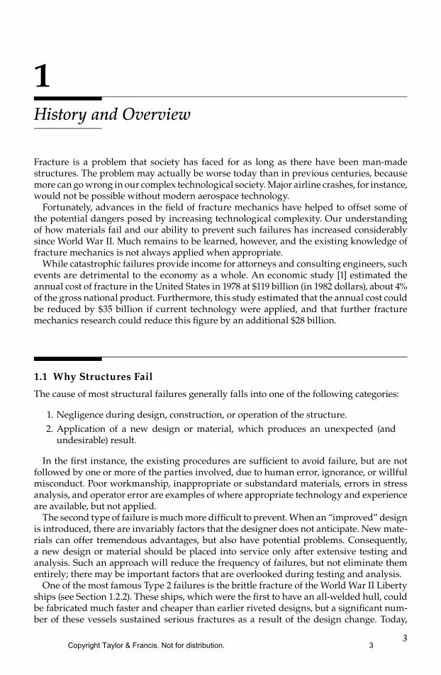
3
1History and Overview
Fracture is a problem that society has faced for as long as there have been man-made structures The problem may actually be worse today than in previous centuries because more can go wrong in our complex technological society Major airline crashes for instance would not be possible without modern aerospace technology
Fortunately advances in the eld of fracture mechanics have helped to offset some of the potential dangers posed by increasing technological complexity Our understanding of how materials fail and our ability to prevent such failures has increased considerably since World War II Much remains to be learned however and the existing knowledge of fracture mechanics is not always applied when appropriate
While catastrophic failures provide income for attorneys and consulting engineers such events are detrimental to the economy as a whole An economic study [1] estimated the annual cost of fracture in the United States in 1978 at $119 billion (in 1982 dollars) about 4 of the gross national product Furthermore this study estimated that the annual cost could be reduced by $35 billion if current technology were applied and that further fracture mechanics research could reduce this gure by an additional $28 billion
11 Why Structures Fail
The cause of most structural failures generally falls into one of the following categories
1 Negligence during design construction or operation of the structure2 Application of a new design or material which produces an unexpected (and
undesirable) result
In the rst instance the existing procedures are sufcient to avoid failure but are not followed by one or more of the parties involved due to human error ignorance or willful misconduct Poor workmanship inappropriate or substandard materials errors in stress analysis and operator error are examples of where appropriate technology and experience are available but not applied
The second type of failure is much more difcult to prevent When an ldquoimprovedrdquo design is introduced there are invariably factors that the designer does not anticipate New mate-rials can offer tremendous advantages but also have potential problems Consequently a new design or material should be placed into service only after extensive testing and analysis Such an approach will reduce the frequency of failures but not eliminate them entirely there may be important factors that are overlooked during testing and analysis
One of the most famous Type 2 failures is the brittle fracture of the World War II Liberty ships (see Section 122) These ships which were the rst to have an all-welded hull could be fabricated much faster and cheaper than earlier riveted designs but a signicant num-ber of these vessels sustained serious fractures as a result of the design change Today
Copyright Taylor amp Francis Not for distribution 3
4 Fracture Mechanics Fundamentals and Applications
virtually all steel ships are welded but sufcient knowledge was gained from the Liberty ship failures to avoid similar problems in present structures
However knowledge must be applied in order to be useful Figure 11 shows an example of a Type 1 failure where poor workmanship in a seemingly inconsequential structural detail caused a more recent fracture in a welded ship In 1979 the Kurdistan oil tanker broke completely into two while sailing in the North Atlantic (Garwood SJ private com-munication 1990) The combination of warm oil in the tanker with cold water in contact with the outer hull produced substantial thermal stresses The fracture initiated from a bilge keel that was improperly welded The weld failed to penetrate the structural detail resulting in a severe stress concentration Although the hull steel had adequate toughness to prevent fracture initiation it failed to stop the propagating crack
Polymers which are becoming more common in structural applications provide a num-ber of advantages over metals but also have the potential for causing Type 2 failures For example polyethylene (PE) is currently the material of choice in natural gas transporta-tion systems in the United States One advantage of PE piping is that maintenance can be performed on a small branch of the line without shutting down the entire system a local area is shut down by applying a clamping tool to the PE pipe and stopping the ow of gas The practice of pinch clamping has undoubtedly saved vast sums of money but has also led to an unexpected problem
In 1983 a section of 4 in diameter PE pipe developed a major leak The gas collected beneath a residence where it ignited resulting in severe damage to the house Maintenance records and a visual inspection of the pipe indicated that it had been pinch clamped 6 years earlier in the region where the leak developed A failure investigation [2] concluded that the pinch clamping operation was responsible for the failure Microscopic examina-tion of the pipe has revealed that a small aw apparently initiated on the inner surface of the pipe and grew through the wall Figure 12 shows a low magnication photograph of the fracture surface Laboratory tests simulated the pinch clamping operation on sections of the PE pipe small thumbnail-shaped aws (Figure 13) formed on the inner wall of the pipes as a result of the severe strains that were applied Fracture mechanics tests and analyses [23] have indicated that stresses in the pressurized pipe were sufcient to cause the observed time-dependent crack growth that is growth from a small thumbnail aw to a through-thickness crack over a period of 6 years
The introduction of aws in PE pipe by pinch clamping represents a Type 2 failure The pinch clamping process was presumably tested thoroughly before it was applied in
(a) (b)
FIGURE 11The MSV Kurdistan oil tanker which sustained a brittle fracture while sailing in the North Atlantic in 1979 (a) Fractured vessel in dry dock and (b) bilge keel from which the fracture initiated (Photographs provided by SJ Garwood)
Copyright Taylor amp Francis Not for distribution 4
5History and Overview
service but no one anticipated that the procedure would introduce damage in the material that could lead to failure after several years in service Although specic data are not avail-able pinch clamping has undoubtedly led to a signicant number of gas leaks The prac-tice of pinch clamping is still widespread in the natural gas industry but many companies and some states now require that a sleeve be tted to the affected region in order to relieve the stresses locally In addition newer grades of PE pipe material have lower density and are less susceptible to damage by pinch clamping
Some catastrophic events include elements both of Types 1 and 2 failures On January 28 1986 the Challenger Space Shuttle exploded because an O-ring seal in one of the main boosters did not respond well to cold weather The Shuttle represents relatively new tech-nology where service experience is limited (Type 2) but engineers from the booster manu-facturer suspected a potential problem with the O-ring seals and recommended that the launch be delayed (Type 1) Unfortunately these engineers had little or no data to support their position and were unable to convince their managers or NASA ofcials The tragic results of the decision to launch are well known
On February 1 2003 almost exactly 17 years after the Challenger accident the Space Shuttle Columbia was destroyed during reentry The apparent cause of the incident was foam insulation from the external tank striking the left wing during launch This debris
1 mm
FIGURE 12Fracture surface of a PE pipe that sustained time-dependent crack growth as a result of pinch clamping (From Jones RE and Bradley WL Forensic Eng 1 47ndash59 1987) (Photograph provided by RE Jones Jr)
1 mm
FIGURE 13Thumbnail crack produced in a PE pipe after pinch clamping for 72 h (Photograph provided by RE Jones Jr)
Copyright Taylor amp Francis Not for distribution 5
6 Fracture Mechanics Fundamentals and Applications
damaged insulation tiles on the underside of the wing making the Orbiter vulnerable to reentry temperatures that can reach 3000degF The Columbia Accident Investigation Board (CAIB) was highly critical of NASA management for cultural traits and organizational practices that according to the Board were detrimental to safety
Over the past few decades the eld of fracture mechanics has undoubtedly prevented a substantial number of structural failures We will never know how many lives have been saved or how much property damage has been avoided by applying this technol-ogy because it is impossible to quantify disasters that do not happen When applied cor-rectly fracture mechanics not only helps to prevent Type 1 failures but also reduces the frequency of failures of the second type because designers can rely on rational analysis rather than on trial and error
12 Historical Perspective
Designing structures to avoid fracture is not a new idea The fact that many structures commissioned by the Pharaohs of ancient Egypt and the Caesars of Rome are still stand-ing is a testimony to the ability of early architects and engineers In Europe numerous buildings and bridges constructed during the Renaissance Period are still used for their intended purpose
The ancient structures that are still standing today obviously represent successful designs There were undoubtedly many more unsuccessful designs that endured a much shorter life span Since mankindrsquos knowledge of mechanics was limited prior to the time of Isaac Newton workable designs were probably achieved largely by trial and error The Romans supposedly tested each new bridge by requiring the design engineer to stand underneath while chariots drove over it Such a practice would not only provide an incen-tive for developing good designs but would also result in a Darwinian natural selection where the worst engineers are removed from the profession
The durability of ancient structures is particularly amazing when one considers that the choice of building materials prior to the Industrial Revolution was rather limited Metals could not be produced in sufcient quantity to be formed into load-bearing members for buildings and bridges The primary construction materials prior to the nineteenth century were timber stone brick and mortar only the latter three materials were usually practical for large structures such as cathedrals because trees of sufcient size for support beams were rare
Stone brick and mortar are relatively brittle and are unreliable for carrying tensile loads Consequently pre-Industrial Revolution structures were usually designed to be loaded in compression Figure 14 schematically illustrates a Roman bridge design The arch shape causes compressive rather than tensile stresses to be transmitted through the structure
The arch is the predominate shape in pre-Industrial Revolution architecture Windows and roof spans were arched in order to maintain compressive loading For example Figure 15 shows two windows and a portion of the ceiling in Kings College Chapel in Cambridge England Although these shapes are aesthetically pleasing their primary purpose is more pragmatic
Compressively loaded structures are obviously stable since some have lasted for many centuries The pyramids in Egypt are the epitome of a stable design
Copyright Taylor amp Francis Not for distribution 6
7History and Overview
With the Industrial Revolution came mass production of iron and steel (Or conversely one might argue that mass production of iron and steel fueled the Industrial Revolution) The availability of relatively ductile construction materials removed the earlier restrictions on design It was nally feasible to build structures that carried tensile stresses Note the difference between the design of the Tower Bridge in London (Figure 16) and the earlier bridge design (Figure 14)
The change from structures loaded in compression to steel structures in tension brought problems however Occasionally a steel structure would fail unexpectedly at stresses well below the anticipated tensile strength One of the most famous of these failures was the rupture of a molasses tank in Boston in January 1919 [4] More than 2 million gallons of molasses was spilled resulting in 12 deaths 40 injuries massive property damage and several drowned horses
The cause of failures as the molasses tank was largely a mystery at the time In the rst edition of his elasticity text published in 1892 Love [5] remarked that ldquothe conditions of rupture are but vaguely understoodrdquo Designers typically applied safety factors of 10 or more (based on the tensile strength) in an effort to avoid these seemingly random failures
FIGURE 14Schematic of Roman bridge design The arch shape of the bridge causes loads to be transmitted through the structure as compressive stresses
FIGURE 15Kings College Chapel in Cambridge England This structure was completed in 1515
Copyright Taylor amp Francis Not for distribution 7
8 Fracture Mechanics Fundamentals and Applications
121 Early Fracture Research
Experiments performed by Leonardo da Vinci several centuries earlier provided some clues as to the root cause of fracture He measured the strength of iron wires and found that the strength varied inversely with wire length These results implied that aws in the material controlled the strength a longer wire corresponded to a larger sample volume and a higher probability of sampling a region containing a aw These results were only qualitative however
A quantitative connection between fracture stress and aw size came from the work of Grifth which was published in 1920 [6] He applied a stress analysis of an elliptical hole (performed by Inglis [7] 7 years earlier) to the unstable propagation of a crack Grifth invoked the rst law of thermodynamics to formulate a fracture theory based on a sim-ple energy balance According to this theory a aw becomes unstable and thus fracture occurs when the strain energy change that results from an increment of crack growth is sufcient to overcome the surface energy of the material (see Section 23) Grifthrsquos model correctly predicted the relationship between strength and aw size in glass specimens Subsequent efforts to apply the Grifth model to metals were unsuccessful Since this model assumes that the work of fracture comes exclusively from the surface energy of the material the Grifth approach only applies to ideally brittle solids A modication to Grifthrsquos model that made it applicable to metals did not come until 1948
122 The Liberty Ships
The mechanics of fracture progressed from being a scientic curiosity to an engineer-ing discipline primarily because of what happened to the Liberty ships during World War II [8]
In the early days of World War II the United States was supplying ships and planes to Great Britain under the Lend-Lease Act Britainrsquos greatest need at the time was for cargo ships to carry supplies The German Navy was sinking cargo ships at three times the rate at which they could be replaced with existing shipbuilding procedures
Under the guidance of Henry Kaiser a famous construction engineer whose previous projects included the Hoover Dam the United States developed a revolutionary procedure
FIGURE 16The Tower Bridge in London completed in 1894 Note the modern beam design made possible by the avail-ability of steel support girders
Copyright Taylor amp Francis Not for distribution 8
9History and Overview
for fabricating ships quickly These new vessels which became known as the Liberty ships had an all-welded hull as opposed to the riveted construction of traditional ship designs
The Liberty Ship Program was a resounding success until one day in 1943 when one of the vessels broke completely into two while sailing between Siberia and Alaska Subsequent fractures occurred in other Liberty ships Of the roughly 2700 Liberty ships built during World War II approximately 400 sustained fractures of which 90 were con-sidered serious In 20 ships the failure was essentially total and about half of these broke completely into two
Investigations have revealed that the Liberty ship failures were caused by a combination of three factors
bull The welds which were produced by a semi-skilled work force contained crack-like aws
bull Most of the fractures initiated on the deck at square hatch corners where there was a local stress concentration
bull The steel from which the Liberty ships were made had poor toughness as mea-sured by Charpy impact tests
The steel in question had always been adequate for riveted ships because fracture could not propagate across panels that were joined by rivets A welded structure however is essentially a single piece of metal propagating cracks in the Liberty ships encountered no signicant barriers and were sometimes able to traverse the entire hull
Once the causes of failure were identied the remaining Liberty ships were retrotted with rounded reinforcements at the hatch corners In addition high toughness steel crack-arrester plates were riveted to the deck at strategic locations These corrections prevented further serious fractures
In the longer term structural steels were developed with vastly improved toughness and weld quality control standards were developed Besides a group of researchers at the Naval Research Laboratory in Washington DC studied the fracture problem in detail The eld we now know as fracture mechanics was born in this laboratory during the decade following the War
123 Postwar Fracture Mechanics Research
The fracture mechanics research group at the Naval Research Laboratory was led by Dr George R Irwin1 After studying the early work of Inglis Grifth and others Irwin con-cluded that the basic tools needed to analyze fracture were already available Irwinrsquos rst major contribution was to extend the Grifth approach to metals by including the energy dissipated by local plastic ow [9] Orowan independently proposed a similar modication to the Grifth theory [10] During this same period Mott [11] extended the Grifth theory to a rapidly propagating crack
In 1956 Irwin [12] developed the energy release rate concept which was derived from the Grifth theory but is in a form that is more useful for solving engineering prob-lems Shortly afterward several of Irwinrsquos colleagues brought to his attention a paper by
1 For an excellent summary of early fracture mechanics research refer to Fracture Mechanics Retrospective Early Classic Papers (1913ndash1965) John M Barsom ed American Society of Testing and Materials (RPS 1) Philadelphia 1987 This volume contains reprints of 17 classic papers as well as a complete bibliography of fracture mechanics papers published up to 1965
Copyright Taylor amp Francis Not for distribution 9
10 Fracture Mechanics Fundamentals and Applications
Westergaard [13] that was published in 1938 Westergaard had developed a semi-inverse technique for analyzing stresses and displacements ahead of a sharp crack Irwin [14] used the Westergaard approach to show that the stresses and displacements near the crack tip could be described by a single constant that was related to the energy release rate This crack tip characterizing parameter later became known as the stress intensity factor During this same period of time Williams [15] applied a somewhat different technique to derive crack tip solutions that were essentially identical to Irwinrsquos results
A number of successful early applications of fracture mechanics bolstered the standing of this new eld in the engineering community In 1956 Wells [16] used fracture mechan-ics to show that the fuselage failures in several Comet jet aircraft resulted from fatigue cracks reaching a critical size These cracks initiated at windows and were caused by insufcient reinforcement locally combined with square corners which produced a severe stress concentration (Recall the unfortunate hatch design in the Liberty ships) A second early application of fracture mechanics occurred at General Electric in 1957 Winne and Wundt [17] applied Irwinrsquos energy release rate approach to the failure of large rotors from steam turbines They were able to predict the bursting behavior of large disks extracted from rotor forgings and applied this knowledge to the prevention of fracture in actual rotors
It seems that all great ideas encounter stiff opposition initially and fracture mechanics is no exception Although the US military and the electric power generating industry were very supportive of the early work in this eld such was not the case in all provinces of government and industry Several government agencies openly discouraged research in this area
In 1960 Paris and his coworkers [18] failed to nd a receptive audience for their ideas on applying fracture mechanics principles to fatigue crack growth Although Paris et al pro-vided convincing experimental and theoretical arguments for their approach it seems that the design engineers were not yet ready to abandon their SndashN curves in favor of a more rigorous approach to fatigue design The resistance to this work was so intense that Paris and his colleagues were unable to nd a peer-reviewed technical journal that was willing to publish their manuscript They nally opted to publish their work in a University of Washington periodical titled The Trend in Engineering
124 Fracture Mechanics from 1960 through 1980
The World War II obviously separates two distinct eras in the history of fracture mechan-ics There is however some ambiguity as to how the period between the end of the War and the present should be divided One possible historical boundary occurs around 1960 when the fundamentals of linear elastic fracture mechanics (LEFM) were fairly well estab-lished and researchers turned their attention to crack tip plasticity
LEFM ceases to be valid when signicant plastic deformation precedes failure During a relatively short time period (1960ndash1961) several researchers developed analyses to correct for yielding at the crack tip including Irwin [19] Dugdale [20] Barenblatt [21] and Wells [22] The Irwin plastic zone correction [19] was a relatively simple extension of LEFM while Dugdale [20] and Barenblatt [21] each developed somewhat more elaborate models based on a narrow strip of yielded material at the crack tip
Wells [22] proposed the displacement of the crack faces as an alternative fracture crite-rion when signicant plasticity precedes failure Previously Wells had worked with Irwin while on sabbatical at the Naval Research Laboratory When Wells returned to his post at the British Welding Research Association he attempted to apply LEFM to low- and
Copyright Taylor amp Francis Not for distribution 10
11History and Overview
medium-strength structural steels These materials were too ductile for LEFM to apply but Wells noticed that the crack faces moved apart with plastic deformation This obser-vation led to the development of the parameter now known as the crack tip opening dis-placement (CTOD)
In 1968 Rice [23] developed another parameter to characterize nonlinear material behav-ior ahead of a crack By idealizing plastic deformation as nonlinear elastic Rice was able to generalize the energy release rate to nonlinear materials He showed that this nonlin-ear energy release rate can be expressed as a line integral which he called the J integral evaluated along an arbitrary contour around the crack At the time his work was being published Rice discovered that Eshelby [24] had previously published several so-called conservation integrals one of which was equivalent to Ricersquos J integral Eshelby however did not apply his integrals to crack problems
That same year Hutchinson [25] and Rice and Rosengren [26] related the J integral to crack tip stress elds in nonlinear materials These analyses have shown that J can be viewed as a nonlinear stress intensity parameter as well as an energy release rate
Ricersquos work might have been relegated to obscurity had it not been for the active research effort by the nuclear power industry in the United States in the early 1970s Due to legiti-mate concerns for safety as well as due to political and public relations considerations the nuclear power industry endeavored to apply state-of-the-art technology including frac-ture mechanics to the design and construction of nuclear power plants The difculty with applying fracture mechanics in this instance was that most nuclear pressure vessel steels were too tough to be characterized with LEFM without resorting to enormous laboratory specimens In 1971 Begley and Landes [27] who were research engineers at Westinghouse came across Ricersquos article and decided despite skepticism from their coworkers to charac-terize fracture toughness of these steels with the J integral Their experiments were very successful and led to the publication of a standard procedure for J testing of metals 10 years later [28]
Material toughness characterization is only one aspect of fracture mechanics To apply fracture mechanics concepts to design one must have a mathematical relationship between toughness stress and aw size Although these relationships were well established for linear elastic problems a fracture design analysis based on the J integral was not available until Shih and Hutchinson [29] provided the theoretical framework for such an approach in 1976 A few years later the Electric Power Research Institute (EPRI) published a fracture design handbook [30] based on the Shih and Hutchinson methodology
In the United Kingdom Wellrsquos CTOD parameter was applied extensively to fracture analysis of welded structures beginning in the late 1960s While fracture research in the United States was driven primarily by the nuclear power industry during the 1970s frac-ture research in the United Kingdom was motivated largely by the development of oil resources in the North Sea In 1971 Burdekin and Dawes [31] applied several ideas pro-posed by Wells [32] several years earlier and developed the CTOD design curve a semiem-pirical fracture mechanics methodology for welded steel structures The nuclear power industry in the United Kingdom developed their own fracture design analysis [33] based on the strip yield model of Dugdale [20] and Barenblatt [21]
Shih [34] demonstrated a relationship between the J integral and CTOD implying that both parameters are equally valid for characterizing fracture The J-based material testing and structural design approaches developed in the United States and the British CTOD methodology have begun to merge in recent years with positive aspects of each approach combined to yield improved analyses Both parameters are currently applied throughout the world to a range of materials
Copyright Taylor amp Francis Not for distribution 11
12 Fracture Mechanics Fundamentals and Applications
Much of the theoretical foundation of dynamic fracture mechanics was developed in the period between 1960 and 1980 Signicant contributions were made by a number of researchers as discussed in Chapter 4
125 Fracture Mechanics from 1980 to the Present
The eld of fracture mechanics matured in the last two decades of the twentieth century Current research tends to result in incremental advances rather than major gains The application of this technology to practical problems is so pervasive that fracture mechanics is now considered an established engineering discipline
More sophisticated models for material behavior are being incorporated into fracture mechanics analyses While plasticity was the important concern in 1960 more recent work has gone a step further incorporating time-dependent nonlinear material behavior such as viscoplasticity and viscoelasticity The former is motivated by the need for tough creep-resistant high-temperature materials while the latter reects the increasing proportion of plastics in structural applications Fracture mechanics has also been used (and sometimes abused) in the characterization of composite materials
Another trend in recent research is the development of microstuctural models for frac-ture and models to relate local and global fracture behavior of materials A related topic is the efforts to characterize and predict geometry dependence of fracture toughness Such approaches are necessary when traditional so-called single-parameter fracture mechanics breaks down
The continuing explosion in computer technology has aided both the development and application of fracture mechanics technology For example an ordinary desktop computer or laptop is capable of performing complex three-dimensional (3D) nite element analyses of structural components that contain cracks As of this writing nite element analysis is not typically performed with tablet computers and smartphones but that situation will likely change before the next edition of this book is published
Computer technology has also spawned entirely new areas of fracture mechan-ics research Problems encountered in the microelectronics industry have led to active research in interface fracture and nanoscale fracture
13 The Fracture Mechanics Approach to Design
Figure 17 contrasts the fracture mechanics approach with the traditional approach to structural design and material selection In the latter case the anticipated design stress is compared with the ow properties of candidate materials a material is assumed to be adequate if its strength is greater than the expected applied stress Such an approach may attempt to guard against brittle fracture by imposing a safety factor on stress combined with minimum tensile elongation requirements on the material The fracture mechan-ics approach (Figure 17b) has three important variables rather than two as shown in Figure 17a The additional structural variable is aw size and fracture toughness replaces strength as the critical material property Fracture mechanics quanties the critical combi-nations of these three variables
Copyright Taylor amp Francis Not for distribution 12
13History and Overview
There are two alternative approaches to fracture analysis the energy criterion and the stress intensity approach These two approaches are equivalent in certain circumstances Both are discussed briey below
131 The Energy Criterion
The energy approach states that crack extension (ie fracture) occurs when the energy available for crack growth is sufcient to overcome the resistance of the material The material resistance may include the surface energy plastic work or other type of energy dissipation associated with a propagating crack
Grifth [6] was the rst to propose the energy criterion for fracture but Irwin [12] is pri-marily responsible for developing the present version of this approach the energy release rate G which is dened as the rate of change in potential energy with crack area for a linear elastic material At the moment of fracture G = Gc the critical energy release rate which is a measure of fracture toughness
For a crack of length 2a in an innite plate subject to a remote tensile stress (Figure 18) the energy release rate is given by
G = πσ2a
E (11)
where E is Youngrsquos modulus σ the remotely applied stress and a is the half crack length At fracture G = Gc and Equation 11 describes the critical combinations of stress and crack size for failure
Gc
f caE
=πσ2
(12)
Note that for a constant Gc value failure stress σf varies with 1 a The energy release rate G is the driving force for fracture while Gc is the materialrsquos resistance to fracture To draw an analogy to the strength of materials approach of Figure 17a the applied stress
Appliedstress
(a)
(b)
Flawsize
Fracturetoughness
Appliedstress
Yield or tensilestrength
FIGURE 17Comparison of the fracture mechanics approach to design with the traditional strength of materials approach (a) the strength of materials approach and (b) the fracture mechanics approach
Copyright Taylor amp Francis Not for distribution 13
14 Fracture Mechanics Fundamentals and Applications
can be viewed as the driving force for plastic deformation while the yield strength is a measure of the materialrsquos resistance to deformation
The tensile stress analogy is also useful for illustrating the concept of similitude A yield strength value measured with a laboratory specimen should be applicable to a large struc-ture yield strength does not depend on specimen size provided the material is reasonably homogeneous One of the fundamental assumptions of fracture mechanics is that fracture toughness (Gc in this case) is independent of the size and geometry of the cracked body a fracture toughness measurement on a laboratory specimen should be applicable to a struc-ture As long as this assumption is valid all conguration effects are taken into account by the driving force G The similitude assumption is valid as long as the material behavior is predominantly linear elastic
132 The Stress Intensity Approach
Figure 19 schematically shows an element near the tip of a crack in an elastic material together with the in-plane stresses on this element Note that each stress component is proportional to a single constant KI If this constant is known the entire stress distribu-tion at the crack tip can be computed with the equations in Figure 19 This constant which is called the stress intensity factor completely characterizes the crack tip conditions in a linear elastic material (The meaning of the subscript on K is explained in Chapter 2) If one assumes that the material fails locally at some critical combination of stress and strain then it follows that fracture must occur at a critical value of stress intensity KIc Thus KIc is an alternate measure of fracture toughness
For the plate illustrated in Figure 18 the stress intensity factor is given by
K aI = σ π (13)
2a
B
σ
FIGURE 18Through-thickness crack in an innite plate subject to a remote tensile stress In practical terms ldquoinniterdquo means that the width of the plate is ≫2a
Copyright Taylor amp Francis Not for distribution 14
15History and Overview
Failure occurs when KI = KIc In this case KI is the driving force for fracture and KIc is a measure of material resistance As with Gc the property of similitude should apply to KIc That is KIc is assumed to be a size-independent material property
Comparing Equations 11 and 13 results in a relationship between KI and G
G = K
EI2
(14)
This same relationship obviously holds for Gc and KIc Thus the energy and stress inten-sity approaches to fracture mechanics are essentially equivalent for linear elastic materials
133 Time-Dependent Crack Growth and Damage Tolerance
Fracture mechanics often plays a role in life prediction of components that are subject to time-dependent crack growth mechanisms such as fatigue or stress corrosion cracking The rate of cracking can be correlated with fracture mechanics parameters such as the stress intensity factor and the critical crack size for failure can be computed if the fracture toughness is known For example the fatigue crack growth rate in metals can usually be described by the following empirical relationship
dadN
C K m= ( )∆ (15)
where dadN is the crack growth per cycle ΔK the stress intensity range and C and m are the material constants
Damage tolerance as its name suggests entails allowing subcritical aws to remain in a structure Repairing awed material or scrapping a awed structure is expensive and is often unnecessary Fracture mechanics provides a rational basis for establishing aw tolerance limits
Consider a aw in a structure that grows with time (eg a fatigue crack or a stress cor-rosion crack) as illustrated schematically in Figure 110 The initial crack size is inferred from nondestructive examination (NDE) and the critical crack size is computed from the applied stress and fracture toughness Normally an allowable aw size would be dened
y
r
Crackx
σyy
τxy
τyx
θ
σxxσ θ θ θ
σ
xxI
yyI
K
K
=
minus
=
2πr 21
232
2πr
cos sin sin
θ θ θ
τ θKxy
I
cos sin sin
cos
21
232
2πr
+
=22 2
32
sin cosθ θ
FIGURE 19Stresses near the tip of a crack in an elastic material
Copyright Taylor amp Francis Not for distribution 15
16 Fracture Mechanics Fundamentals and Applications
by dividing the critical size by a safety factor The predicted service life of the structure can then be inferred by calculating the time required for the aw to grow from its initial size to the maximum allowable size
14 Effect of Material Properties on Fracture
Figure 111 shows a simplied family tree for the eld of fracture mechanics Most early work was applicable only to linear elastic materials under quasistatic conditions while subsequent advances in fracture research incorporated other types of material behavior Elasticndashplastic fracture mechanics considers plastic deformation under quasistatic condi-tions while dynamic viscoelastic and viscoplastic fracture mechanics include time as a variable A dashed line is drawn between linear elastic and dynamic fracture mechanics because some early research considered dynamic linear elastic behavior The chapters that
Flawsize
Failure
Time
Useful service life
FIGURE 110The damage tolerance approach to design
Linear elasticfracture
mechanics
Lineartime-independent
materials(Chapter 2)
Nonlineartime-independent
materials(Chapter 3)
Dynamicfracture
mechanics
Viscoelasticfracture
mechanics
Viscoplasticfracture
mechanics
Time-dependentmaterials
(Chapter 4)
Elasticndashplasticfracture
mechanics
FIGURE 111Simplied family tree of fracture mechanics
Copyright Taylor amp Francis Not for distribution 16
17History and Overview
describe the various types of fracture behavior are shown in Figure 111 Elasticndashplastic viscoelastic and viscoplastic fracture behavior are sometimes included in the more gen-eral heading of nonlinear fracture mechanics The branch of fracture mechanics one should apply to a particular problem obviously depends on the material behavior Table 11 lists the typical fracture behavior of various engineering materials
Consider a cracked plate (Figure 18) that is loaded to failure Figure 112 is a schematic plot of failure stress versus fracture toughness (KIc) For low toughness materials brittle fracture is the governing failure mechanism and critical stress varies linearly with KIc as predicted by Equation 13 At very high toughness values LEFM is no longer valid and failure is governed by the ow properties of the material At intermediate toughness lev-els there is a transition between brittle fracture under linear elastic conditions and ductile overload Nonlinear fracture mechanics bridges the gap between LEFM and collapse If toughness is low LEFM is applicable to the problem but if toughness is sufciently high fracture mechanics ceases to be relevant to the problem because failure stress is insensitive to toughness a simple limit load analysis is all that is required to predict failure stress in a material with very high fracture toughness
15 A Brief Review of Dimensional Analysis
At rst glance a section on dimensional analysis may seem out of place in the introduc-tory chapter of a book on fracture mechanics However dimensional analysis is an impor-tant tool for developing mathematical models of physical phenomena and it can help us understand the existing models Many difcult concepts in fracture mechanics become relatively transparent when one considers the relevant dimensions of the problem For example dimensional analysis gives us a clue as to when a particular model such as LEFM is no longer valid
Failurestress
Collapse
2a
σ
LEFMBritt
le frac
ture
Nonlinear fracturemechanics
Limit loadanalysis
Fracture toughness (KIc)
FIGURE 112Effect of fracture toughness on the governing failure mechanism
Copyright Taylor amp Francis Not for distribution 17
18 Fracture Mechanics Fundamentals and Applications
Let us review the fundamental theorem of dimensional analysis and then look at a few simple applications to fracture mechanics
151 The Buckingham Π-Theorem
The rst step in building a mathematical model of a physical phenomenon is to identify all of the parameters that may inuence the phenomenon Assume that a problem or at least an idealized version of it can be described by the following set of scalar quantities u W1 W2 hellip Wn The dimensions of all quantities in this set are denoted by [u] [W1] [W2] hellip [Wn] Now suppose that we wish to express the rst variable u as a function of the remain-ing parameters
u f W W Wn= ( )1 2 hellip (16)
Thus the process of modeling the problem is reduced to nding a mathematical relation-ship that represents f as best as possible We might accomplish this by performing a set of experiments in which we measure u while varying each Wi independently The number of experiments can be greatly reduced and the modeling processes simplied through dimensional analysis The rst step is to identify all of the fundamental dimensional units (fdursquos) in the problem L1 L2 hellip Lm For example a typical mechanics problem may have L1 = length L2 = mass L3 = time We can express the dimensions of each quantity in our problem as the product of powers of the fdursquos that is for any quantity X we have
[ ]X L L La amam= 1 2
1 2 (17)
The quantity X is dimensionless if [X] = 1In the set of Ws we can identify m primary quantities that contain all of the fdursquos in the
problem The remaining variables are secondary quantities and their dimensions can be expressed in terms of the primary quantities
[ ] [ ] [ ] ( )( ) ( )W W W j n mm ja
mam j m j m
+ = = hellip minus+ +1
1 1 2 (18)
Thus we can dene a set of new quantities πi that are dimensionless
πi
m ja
ma
W
W Wm j m j m= +
+ +1
1( ) ( ) (19)
Similarly the dimensions of u can be expressed in terms of the dimensions of the pri-mary quantities
[ ] [ ] [ ]u W Wam
am= 11 (110)
Thus we can form the following dimensionless quantity
π = u
W Wamam
11
(111)
Copyright Taylor amp Francis Not for distribution 18
19History and Overview
According to the Buckingham Π-theorem π depends only on the other dimensionless groups
π π π π= hellip minusF n m( )1 2 (112)
This new function F is independent of the system of measurement units Note that the number of quantities in F has been reduced from the old function by m the number of fdursquos Thus dimensional analysis has reduced the degrees of freedom in our model and we need to vary only n minus m quantities in our experiments or computer simulations
The Buckingham Π-theorem gives guidance on how to scale a problem to different sizes or to other systems of measurement units Each dimensionless group (πi) must be scaled in order to obtain equivalent conditions at two different scales Suppose for example that we wish to perform wind tunnel tests on a model of a new airplane design Dimensional analysis tells us that we should reduce all length dimensions in the same proportion thus we would build a ldquoscalerdquo model of the airplane The length dimensions of the plane are not the only important quantities in the problem however To model the aerodynamic behavior accurately we would need to scale the wind velocity and the viscosity of the air in accordance with the reduced size of the airplane model Modifying the viscosity of air is not practical in most cases In real wind tunnel tests the size of the model is usually close enough to full scale that the errors introduced by the nonscaling viscosity are minor
152 Dimensional Analysis in Fracture Mechanics
Dimensional analysis proves to be a very useful tool in fracture mechanics The later chapters describe how dimensional arguments play a key role in developing mathemati-cal descriptions for important phenomena For now let us explore a few simple examples
Consider a series of cracked plates under a remote tensile stress σinfin as illustrated in Figure 113 Assume that each to be a two-dimensional (2D) problem that is the thickness dimension does not enter into the problem The rst case Figure 113a is an edge crack of length a in an elastic semi-innite plate In this case innite means that the plate width is much larger than the crack size Suppose that we wish to know how one of the stress
a a a
W
(a) (b) (c)
σinfin σinfin σinfin
W
ry
Plasticzone
FIGURE 113Edge-cracked plates subject to a remote tensile stress (a) edge crack in a wide elastic plate (b) edge crack in a nite width elastic plate and (c) edge crack with a plastic zone at the crack tip
Copyright Taylor amp Francis Not for distribution 19
20 Fracture Mechanics Fundamentals and Applications
components σij varies with position We will adopt a polar coordinate system with the origin at the crack tip as illustrated in Figure 19 A generalized functional relationship can be written as
σ σ ν σ ε θij kl klf E a r= infin1( ) (113)
where ν is Poissonrsquos ratio σkl represents the other stress components and εkl represents all nonzero components of the strain tensor We can eliminate σkl and εkl from f1 by noting that for a linear elastic problem strain is uniquely dened by stress through Hookersquos law and the stress components at a point increase in proportion to one another Let σinfin and a be the primary quantities Invoking the Buckingham Π-theorem gives
σσ σ
ν θij FE r
ainfin infin=
1
(114)
When the plate width is nite (Figure 113b) an additional dimension is required to describe the problem
σσ σ
ν θij FE r
aWainfin infin=
2
(115)
Thus one might expect Equation 114 to give erroneous results when the crack extends across a signicant fraction of the plate width Consider a large plate and a small plate made of the same material (same E and ν) with the same aW ratio loaded to the same remote stress The local stress at an angle θ from the crack plane in each plate would depend only on the ra ratio as long as both plates remained elastic
When a plastic zone forms ahead of the crack tip (Figure 113c) the problem is compli-cated further If we assume that the material does not strain harden the yield strength is sufcient to dene the ow properties The stress eld is given by
TABLE 11
Typical Fracture Behavior of Selected Materials
Material Typical Fracture Behavior
High-strength steel Linear elasticLow- and medium-strength steel Elasticndashplasticfully plasticAustenitic stainless steel Fully plasticPrecipitation-hardened aluminum Linear elasticMetals at high temperatures ViscoplasticMetals at high strain rates DynamicndashviscoplasticPolymers (below Tg)a Linear elasticviscoelasticPolymers (above Tg)a ViscoelasticMonolithic ceramics Linear elasticCeramic composites Linear elasticCeramics at high temperatures Viscoplastic
Note Temperature is ambient unless otherwise specieda TgmdashGlass transition temperature
Copyright Taylor amp Francis Not for distribution 20
21History and Overview
σσ σ
σσ
ν θij YS yFE r
aWa
ra
=
3 (116)
The rst two functions F1 and F2 correspond to LEFM while F3 is an elasticndashplastic relationship Thus dimensional analysis tells us that LEFM is valid only when ry ≪ a and σinfin ≪ σYS In Chapter 2 the same conclusion is reached through a somewhat more compli-cated argument
References
1 Duga JJ Fisher WH Buxbaum RW Roseneld AR Burh AR Honton EJ and McMillan SC The Economic Effects of Fracture in the United States NBS Special Publication 647-2 United States Department of Commerce Washington DC March 1983
2 Jones RE and Bradley WL Failure analysis of a polyethylene natural gas pipeline Forensic Engineering 1 1987 47ndash59
3 Jones RE and Bradley WL Fracture Toughness Testing of Polyethylene Pipe Materials ASTM STP 995 Vol 1 American Society for Testing and Materials Philadelphia pp 447ndash456 1989
4 Shank ME A critical review of brittle failure in carbon plate steel structures other than ships Ship Structure Committee Report SSC-65 National Academy of Science-National Research Council Washington DC December 1953
5 Love AEH A Treatise on the Mathematical Theory of Elasticity Dover Publications New York 1944
6 Grifth AA The phenomena of rupture and ow in solids Philosophical Transactions Series A 221 1920 163ndash198
7 Inglis CE Stresses in a plate due to the presence of cracks and sharp corners Transactions of the Institute of Naval Architects 55 1913 219ndash241
8 Bannerman DB and Young RT Some improvements resulting from studies of welded ship failures Welding Journal 25 1946 223ndash236
9 Irwin GR Fracture dynamics Fracturing of Metals American Society for Metals Cleveland pp 147ndash166 1948
10 Orowan E Fracture and strength of solids Reports on Progress in Physics XII 1948 185ndash232 11 Mott NF Fracture of metals Theoretical considerations Engineering 165 1948 16ndash18 12 Irwin GR Onset of fast crack propagation in high strength steel and aluminum alloys
Sagamore Research Conference Proceedings 2 1956 289ndash305 13 Westergaard HM Bearing pressures and cracks Journal of Applied Mechanics 6 1939 49ndash53 14 Irwin GR Analysis of stresses and strains near the end of a crack traversing a plate Journal
of Applied Mechanics 24 1957 361ndash364 15 Williams ML On the stress distribution at the base of a stationary crack Journal of Applied
Mechanics 24 1957 109ndash114 16 Wells AA The condition of fast fracture in aluminum alloys with particular reference to
comet failures British Welding Research Association Report April 1955 17 Winne DH and Wundt BM Application of the Grifth-Irwin theory of crack propagation to
the bursting behavior of disks including analytical and experimental studies Transactions of the American Society of Mechanical Engineers 80 1958 1643ndash1655
18 Paris PC Gomez MP and Anderson WP A rational analytic theory of fatigue The Trend in Engineering 13 1961 9ndash14
19 Irwin GR Plastic zone near a crack and fracture toughness Sagamore Research Conference Proceedings Vol 4 Syracuse University Research Institute Syracuse NY pp 63ndash78 1961
Copyright Taylor amp Francis Not for distribution 21
22 Fracture Mechanics Fundamentals and Applications
20 Dugdale DS Yielding in steel sheets containing slits Journal of the Mechanics and Physics of Solids 8 1960 100ndash104
21 Barenblatt GI The mathematical theory of equilibrium cracks in brittle fracture Advances in Applied Mechanics Vol VII Academic Press New York pp 55ndash129 1962
22 Wells AA Unstable crack propagation in metals Cleavage and fast fracture Proceedings of the Crack Propagation Symposium Vol 1 Paper 84 Craneld UK 1961
23 Rice JR A path independent integral and the approximate analysis of strain concentration by notches and cracks Journal of Applied Mechanics 35 1968 379ndash386
24 Eshelby JD The continuum theory of lattice defects Solid State Physics 3 1956 79ndash144 25 Hutchinson JW Singular behavior at the end of a tensile crack tip in a hardening material
Journal of the Mechanics and Physics of Solids 16 1968 13ndash31 26 Rice JR and Rosengren GF Plane strain deformation near a crack tip in a power-law hard-
ening material Journal of the Mechanics and Physics of Solids 16 1968 1ndash12 27 Begley J A and Landes JD The J-Integral as a Fracture Criterion ASTM STP 514 American
Society for Testing and Materials Philadelphia pp 1ndash20 1972 28 E 813-81 Standard Test Method for JIc a Measure of Fracture Toughness American Society for
Testing and Materials Philadelphia 1981 29 Shih CF and Hutchinson JW Fully plastic solutions and large-scale yielding estimates for
plane stress crack problems Journal of Engineering Materials and Technology 98 1976 289ndash295 30 Kumar V German MD and Shih CF An engineering approach for elastic-plastic fracture
analysis EPRI Report NP-1931 Electric Power Research Institute Palo Alto CA 1981 31 Burdekin FM and Dawes MG Practical use of linear elastic and yielding fracture mechanics
with particular reference to pressure vessels Proceedings of the Institute of Mechanical Engineers Conference London pp 28ndash37 May 1971
32 Wells AA Application of fracture mechanics at and beyond general yielding British Welding Journal 10 1963 563ndash570
33 Harrison RP Loosemore K Milne I and Dowling AR Assessment of the integrity of structures containing defects Central Electricity Generating Board Report RHR6-Rev 2 April 1980
34 Shih CF Relationship between the J-integral and the crack opening displacement for station-ary and extending cracks Journal of the Mechanics and Physics of Solids 29 1981 305ndash326
Copyright Taylor amp Francis Not for distribution 22
Chapter 1
Units associated with basicelectrical quantities
At the end of this chapter you should be able to
bull state the basic SI units
bull recognize derived SI units
bull understand prefixes denoting multiplication and division
bull state the units of charge force work and power and perform simple calculations involving these units
bull state the units of electrical potential emf resistance conductance power and energy and perform simplecalculations involving these units
11 SI units
The system of units used in engineering and science isthe Systegraveme Internationale drsquoUniteacutes (International sys-tem of units) usually abbreviated to SI units and isbased on the metric system This was introduced in 1960and is now adopted by the majority of countries as theofficial system of measurement
The basic units in the SI system are listed with theirsymbol s i n Tabl e 11
Derived SI units use combinations of basic units andthere are many of them Two examples are
bull Velocity mdash metres per second (ms)
bull Acceleration mdash metres per second squared (ms2)
SI units may be made larger or smaller by using prefixeswhich denote multiplication or division by a particu-lar amount The six most common multiples with theirmeaning are listed in Table 12 For a more completel i st of prefixes see page 4
Table 11 Basic SI Units
Quantity Unit
length metre m
mass kilogram kg
time second s
electric current ampere A
thermodynamic temperature kelvin K
luminous intensity candela cd
amount of substance mole mol
12 Charge
The unit of charge is the coulomb (C) whereone coulomb is one ampere second (1 coulomb =624times1018 electrons) The coulomb is defined as thequantity of electricity which flows past a given point
DOI 101016B978-1-85617-770-200001-X
Copyright Taylor amp Francis Not for distribution 23
Part
1
4 Electrical Circuit Theory and Technology
Table 12
Prefix Name Meaning
M mega multiply by 1 000 000 (ie times106)
k kilo multiply by 1000 (ie times103)
m milli divide by 1000 (ie times10minus3)
micro micro divide by 1 000 000 (ie times10minus6)
n nano divide by 1 000 000 000 (ie times10minus9)
p pico divide by 1 000 000 000 000 (ie times10minus12)
in an electric circuit when a current of one ampere ismaintained for one second Thus
charge in coulombs Q=It
where I is the current in amperes and t is the time inseconds
Problem 1 If a current of 5 A flows for 2minutes find the quantity of electricity transferred
Quantity of electricity Q = It coulombs
I =5 A t =2times60=120 s
Hence Q =5times120=600 C
13 Force
The unit of force is the newton (N) where one newtonis one kilogram metre per second squared The newtonis defined as the force which when applied to a mass ofone kilogram gives it an acceleration of one metre persecond squared Thus
force in newtons F=ma
where m is the mass in kilograms and a is the accelera-tion in metres per second squared Gravitational forceor weight is mg where g =981 ms2
Problem 2 A mass of 5000 g is accelerated at2 ms2 by a force Determine the force needed
Force=masstimesacceleration
=5 kgtimes2 ms2 =10kg m
s2 =10 N
Problem 3 Find the force acting verticallydownwards on a mass of 200 g attached to a wire
Mass=200 g=02 kg and acceleration due to gravityg =981 ms2
Force acting downwards=weight=masstimesacceleration
=02 kgtimes981 ms2
=1962 N
14 Work
The unit of work or energy is the joule (J) where onejoule is one newton metre The joule is defined as thework done or energy transferred when a force of onenewton is exerted through a distance of one metre in thedirection of the force Thus
work done on a body in joules W =Fs
where F is the force in newtons and s is the distance inmetres moved by the body in the direction of the forceEnergy is the capacity for doing work
15 Power
The unit of power is the watt (W) where one watt is onejoule per second Power is defined as the rate of doingwork or transferring energy Thus
power in watts P= Wt
where W is the work done or energy transferred in joulesand t is the time in seconds Thus
energy in joules W =Pt
Copyright Taylor amp Francis Not for distribution 24
Part
1
Units associated with basic electrical quantities 5
Problem 4 A portable machine requires a forceof 200 N to move it How much work is done if themachine is moved 20 m and what average power isutilized if the movement takes 25 s
Work done = force times distance = 200 N times 20 m
= 4000 Nm or 4 kJ
Power = work done
time taken= 4000 J
25 s= 160 Js=160 W
Problem 5 A mass of 1000 kg is raised through aheight of 10 m in 20 s What is (a) the work doneand (b) the power developed
(a) Work done=forcetimesdistance and
force=masstimesacceleration
Hence work done= (1000 kgtimes981 ms2)times (10 m)
=98 100 Nm
=981 kNm or 981 kJ
(b) Power= work done
time taken= 98 100 J
20 s= 4905 Js
=4905 W or 4905 kW
Now try the following exercise
Exercise 1 Further problems on unitsassociated with basic electricalquantities
(Take g=981 ms2 where appropriate)
1 What force is required to give a mass of 20 kgan acceleration of 30 ms2 [600 N]
2 Find the accelerating force when a car havinga mass of 17 Mg increases its speed with aconstant acceleration of 3 ms2 [51 kN]
3 A force of 40 N accelerates a mass at 5 ms2Determine the mass [8 kg]
4 Determine the force acting downwardson a mass of 1500 g suspended on astring [1472 N]
5 A force of 4 N moves an object 200 cm in thedirection of the force What amount of workis done [8 J]
6 A force of 25 kN is required to lift a loadHow much work is done if the load is liftedthrough 500 cm [125 kJ]
7 An electromagnet exerts a force of 12 N andmoves a soft iron armature through a dis-tance of 15 cm in 40 ms Find the powerconsumed [45 W]
8 A mass of 500 kg is raised to a height of 6 min 30 s Find (a) the work done and (b) thepower developed
[(a) 2943 kNm (b) 981 W]
9 What quantity of electricity is carried by624times1021 electrons [1000 C]
10 In what time would a current of 1 A transfera charge of 30 C [30 s]
11 A current of 3 A flows for 5 minutes Whatcharge is transferred [900 C]
12 How long must a current of 01 A flow so asto transfer a charge of 30 C [5 minutes]
13 Rewrite the following as indicated(a) 1000 pF= nF(b) 002microF= pF(c) 5000 kHz= MHz(d) 47 k= M(e) 032 mA= microA
[(a) 1 nF (b) 20 000 pF (c) 5 MHz(d) 0047 M (e) 320microA]
16 Electrical potential and emf
The unit of electric potential is the volt (V) where onevolt is one joule per coulomb One volt is defined as thedifference in potential between two points in a conductorwhich when carrying a current of one ampere dissipatesa power of one watt ie
volts = watts
amperes= joulessecond
amperes
= joules
ampere seconds= joules
coulombs
A change in electric potential between two points inan electric circuit is called a potential difference Theelectromotive force (emf) provided by a source ofenergy such as a battery or a generator is measured involts
Copyright Taylor amp Francis Not for distribution 25
Part
1
6 Electrical Circuit Theory and Technology
17 Resistance and conductance
The unit of electric resistance is the ohm () whereone ohm is one volt per ampere It is defined as theresistance between two points in a conductor when aconstant electric potential of one volt applied at the twopoints produces a current flow of one ampere in theconductor Thus
resistance in ohms R= VI
where V is the potential difference across the two pointsin volts and I is the current flowing between the twopoints in amperes
The reciprocal of resistance is called conductanceand is measured in siemens (S) Thus
conductance in siemens G= 1R
where R is the resistance in ohms
Problem 6 Find the conductance of a conductorof resistance (a) 10 (b) 5 k and (c) 100 m
(a) Conductance G = 1
R= 1
10siemen=01 S
(b) G = 1
R= 1
5times103S=02times10minus3 S=02 mS
(c) G = 1
R= 1
100times10minus3 S= 103
100S=10 S
18 Electrical power and energy
When a direct current of I amperes is flowing in an elec-tric circuit and the voltage across the circuit is V voltsthen
power in watts P = VI
Electrical energy = Power times time
= VIt Joules
Although the unit of energy is the joule when deal-ing with large amounts of energy the unit used is thekilowatt hour (kWh) where
1 kWh = 1000 watt hour
= 1000 times 3600 watt seconds or joules
= 3 600 000 J
Problem 7 A source emf of 5 V supplies acurrent of 3 A for 10 minutes How much energy isprovided in this time
Energy=powertimes time and power=voltagetimescurrentHence
Energy=VIt =5times3times (10times60)=9000 Ws or J
=9 kJ
Problem 8 An electric heater consumes 18 MJwhen connected to a 250 V supply for 30 minutesFind the power rating of the heater and the currenttaken from the supply
Energy =powertimes time hence
power = energy
time
= 18 times 106 J
30 times 60 s=1000 Js=1000 W
ie Power rating of heater=1 kW
Power P =VI thus I = P
V= 1000
250=4 A
Hence the current taken from the supply is 4 A
Now try the following exercise
Exercise 2 Further problems on unitsassociated with basic electricalquantities
1 Find the conductance of a resistor of resistance(a) 10 (b) 2 k (c) 2 m
[(a) 01 S (b) 05 mS (c) 500 S]
2 A conductor has a conductance of 50microS Whatis its resistance [20 k]
3 An emf of 250 V is connected across aresistance and the current flowing through theresistance is 4 A What is the power developed
[1 kW]
4 450 J of energy are converted into heat in1 minute What power is dissipated [75 W]
5 A current of 10 A flows through a conductorand 10 W is dissipated What pd exists acrossthe ends of the conductor [1 V]
Copyright Taylor amp Francis Not for distribution 26
Part
1
Units associated with basic electrical quantities 7
6 A battery of emf 12 V supplies a currentof 5 A for 2 minutes How much energy issupplied in this time [72 kJ]
7 A dc electric motor consumes 36 MJ when con-nected to a 250 V supply for 1 hour Find thepower rating of the motor and the current takenfrom the supply [10 kW 40 A]
19 Summary of terms units andtheir symbols
Quantity Quantity Unit UnitSymbol Symbol
Length l metre m
Mass m kilogram kg
Time t second s
Velocity v metres per ms orsecond msminus1
Acceleration a metres per ms2 orsecond msminus2
squared
Force F newton N
Electrical Q coulomb Ccharge orquantity
Electric current I ampere A
Resistance R ohm
Conductance G siemen S
Electromotive E volt Vforce
Potential V volt Vdifference
Work W joule J
Energy E (or W) joule J
Power P watt W
As progress is made through Electrical Circuit Theoryand Technology many more terms will be met A fulllist of electrical quantities together with their symbolsand uni t s are given i n Part 4 page 725
Copyright Taylor amp Francis Not for distribution 27
C H A P T E R
EAL Unit Elec201
Learning outcomes
When you have completed this chapter you should1 Understand how health and safety applies to electrotechnical
operations
2 Understand health and safety procedures in the work environment
3 Understand the basic electrical safety requirements
4 Know the safety requirements for using access equipment
5 Understand the importance of establishing a safe working environment (i)
6 Understand the importance of establishing a safe working environment (ii)
Health and safety in electrical installation
1
EA
L E
lect
rica
l Ins
talla
tio
n W
ork
ndash L
evel
2 9
78 1
138
917
14 9
copy 2
016
Lins
ley
Pub
lishe
d b
y Ta
ylor
amp F
ranc
is A
ll rig
hts
rese
rved
Copyright Taylor amp Francis Not for distribution 28
2 1 EAL Electrical Installation Work Level 2
Introduction
Understanding how health and safety is legislated and put into practice is essential for anyone operating within the electrical installation industry Defi ning how statutory regulation ties in with non-statutory codes of practice such as application of wiring regulations is essential as is understanding the roles and responsibilities within health and safety These range from employers to the Health and Safety Executive (HSE) and from employees to safety representatives all with a common aim to learn and inform so that such events are not repeated
Understanding how reduced electrical systems bring about a reduction in electric shocks is paramount in essence the likelihood of being exposed to live parts is lessened Such measures are complemented through a regime that inspects and tests all electrical equipment and ensures that all work is made safe through incorporating safe isolation procedures Safety is also applied when using access equipment so that the user can choose the most appropriate equipment through current Prefabricated Access Suppliersrsquo and Manufacturersrsquo Association (PASMA) requirements Understanding how employers implement a safe system of work is fundamental in instigating risk assessments in order to recognize hazards control through permit-to-work systems and defi ne operations through method statements which signpost exactly how a task is to be implemented It is essential to understand that personal protective equipment (PPE) only lessens the effects of accidents and does not eliminate them and is only necessary when hazards cannot be eliminated The exposure to hazards could also be minimized if less hazardous substances are used the hazard is enclosed or employees are fully trained with only authorized personnel permitted to operate certain hazardous environments and equipment in particular when asbestos is involved The use of signage fi re-fi ghting equipment and training also ensure measures are in place to deal with situations during emergencies
Assessment criteria 11
State the general aims of health and safety legislation
Safety regulations and laws
At the beginning of the nineteenth century children formed a large part of the working population of Great Britain They started work early in their lives and they worked long hours for unscrupulous employers or masters
The Health and Morals of Apprentices Act of 1802 was introduced by Robert Peel in an attempt to reduce apprentice working hours to 12 hours per day and to improve the conditions of their employment The Factories Act of 1833 restricted the working week for children aged 13ndash18 years to 69 hours in any working week
With the introduction of the Factories Act of 1833 the fi rst four full-time Factory Inspectors were appointed They were allowed to employ a small number of assistants and were given the responsibility of inspecting factories throughout England Scotland Ireland and Wales This small overworked band of men
Figure 11 Wearing PPE lessens the impact of accidents but does not eliminate them
Copyright Taylor amp Francis Not for distribution 29
3Health and safety in electrical installationHealth and safety in electrical installation 1were the forerunners of the modern HSE Inspectorate enforcing the safety laws passed by Parliament As the years progressed new Acts of Parliament increased the powers of the Inspectorate and the growing strength of the trade unions meant that employers were increasingly being pressed to improve health safety and welfare at work
The most important recent piece of health and safety law the Health and Safety at Work Act was passed by Parliament in 1974 This Act gave added powers to the Inspectorate and is the basis of all modern statutory health and safety laws This law not only increased the employerrsquos liability for safety measures but also put the responsibility for safety on employees too
Health safety and welfare legislation has increased the awareness of everyone to the risks involved in the workplace All statutes within the Acts of Parliament must be obeyed and therefore we all need an understanding of the laws as they apply to the electrical industry This is the fundamental aim of health and safety legislation
Assessment criteria 12
Recognize the legal status of health and safety documents
Statutory lawsActs of Parliament are made up of statutes Statutory regulations have been passed by Parliament and have therefore become laws Non-compliance with the laws of this land may lead to prosecution by the courts and possible imprisonment for offenders
We shall now look at some of the statutory regulations as they apply not only to employers employees and contractors within the electrical industry but equally to visitors on-site
The Health and Safety at Work Act 1974
Many governments have passed laws aimed at improving safety at work but the most important recent legislation has been the Health and Safety at Work Act 1974 This Act should be thought of as an umbrella Act that other statutory legislation sits under The purpose of the Act is to provide the legal framework for stimulating and encouraging high standards of health and safety at work the Act puts the responsibility for safety at work on both workers and managers
Duty of Care
The employer has a duty to care for the health and safety of employees (Section 2 of the Act) To do this he or she must ensure that
l the working conditions and standard of hygiene are appropriatel the plant tools and equipment are properly maintainedl the necessary safety equipment ndash such as PPE dust and fume extractors and
machine guards ndash is available and properly usedl the workers are trained to use equipment and plant safely
Defi nition
Statutory regulations have been passed by Parliament and have therefore become laws
Top tip
A statutory law is an Act of Parliament
Top tip
HSE applies to both employers and employees to secure the welfare of everyone involved
Figure 12 Both workers and managers are responsible for health and safety on-site
Copyright Taylor amp Francis Not for distribution 30
4 1 EAL Electrical Installation Work Level 2
Failure to comply with the Health and Safety at Work Act is a criminal offence and any infringement of the law can result in heavy fi nes a prison sentence or both This would apply to an employer who could be prosecuted if knowingly allowing an employee to work and that employee then places other people at risk or possible injury
Employees have a duty to care for their own health and safety and that of others who may be affected by their actions including fellow employees and members of the public (Section 7 of the Act) To do this they must
l take reasonable care to avoid injury to themselves or others as a result of their work activity
l co-operate with their employer helping him or her to comply with the requirements of the Act
l not interfere with or misuse anything provided to protect their health and safety
The Electricity at Work Regulations 1989 (EWR)
This legislation came into force in 1990 and replaced earlier regulations such as the Electricity (Factories Act) Special Regulations 1944 The regulations are made under the Health and Safety at Work Act 1974 and enforced by the Health and Safety Executive The purpose of the regulations is to lsquorequire precautions to be taken against the risk of death or personal injury from electricity in work activitiesrsquo
Section 4 of the EWR tells us that lsquoall systems must be constructed so as to prevent danger hellip and be properly maintained hellip Every work activity shall be carried out in a manner which does not give rise to danger hellip In the case of work of an electrical nature it is preferable that the conductors be made dead before work commencesrsquo
The EWR do not tell us specifi cally how to carry out our work activities but they can be used in a court of law as evidence to claim compliance with other statutory requirements If proceedings were brought against an individual for breaking the EWR the only acceptable defence would be lsquoto prove that all reasonable steps were taken and all diligence exercised to avoid the offencersquo (Regulation 29)
An electrical contractor could reasonably be expected to have lsquoexercised all diligencersquo if the installation was wired according to the IET Wiring Regulations (see below) However electrical contractors must become more lsquolegally awarersquo following the conviction of an electrician for manslaughter at Maidstone Crown Court in 1989 The court accepted that an electrician had caused the death of another man as a result of his shoddy work in wiring up a central heating system He received a nine-month suspended prison sentence This case has set an important legal precedent and in future any tradesman or professional who causes death through negligence or poor workmanship risks prosecution and possible imprisonment
The EWR is split into 16 regulations of its own These regulations apply to any person who is engaged with electrical work employers the self-employed and employees including apprentices
Copyright Taylor amp Francis Not for distribution 31
5Health and safety in electrical installationHealth and safety in electrical installation 1
Regulation 1 Citation and commencement
The fi rst regulation puts the EWR into context and cites that the EWR came into force on 1 April 1990
Regulation 2 Interpretation
Introduces certain terms used in the EWR such as how we defi ne system and conductor and even what we mean by lsquodangerrsquo
A system for instance is defi ned as an electrical system in which all the electrical equipment is or may be electrically connected to a common source of electrical energy
This means that the term lsquosystemrsquo includes all the constituent parts of a system including the conductors and all the electrical equipment that fi ts within it
lsquoElectrical equipmentrsquo as defi ned in the regulations includes every type of electrical equipment from for example a 400kV overhead line to a battery-powered hand lamp The reason that the EWR applies to even low-powered equipment is that although the risk of electric shock may be low there could still be a risk of explosion for example
Figure 13 This kind of wiring is unacceptable in the UK as a result of the IET Wiring Regulations
Figure 14 The socket is one of the few parts of the electrical system that our customers see every day
Figure 15a and 15b lsquoThe Wiring Regulations defi ne everything from overhead lines to hand lamps as electrical equipment
Copyright Taylor amp Francis Not for distribution 32
6 1 EAL Electrical Installation Work Level 2
A very important distinction is made regarding the terms lsquochargedrsquo and lsquoliversquo This is because when electricians carry out safe isolation procedures they must ensure that all forms of energy are removed from a circuit including any batteries or other devices such as capacitors that can store charge
Consequently the term lsquodeadrsquo means a conductor that is not lsquoliversquo or lsquochargedrsquo
Regulation 3 Persons on whom duties are imposed by these Regulations
This regulation gives a clear statement of who the EWR applies to and makes a statement
It shall be the duty of every employee while at work to comply with the provisions of these regulations in so far as they relate to matters which are within hisher control
This means that trainee electricians although not fully qualifi ed must adhere to the EWR as well as always cooperating with their employer The EWR also applies to non-technical personnel such as offi ce workers for instance who must realize what they can or cannot do regarding electrical equipment and the importance of not interfering with safety equipment
The EWR also defi nes the distinction between the terms lsquoabsolutersquo and lsquoreasonably practicablersquo lsquoAbsolutersquo means that something must be met irrespective of time or cost While lsquoreasonably practicablersquo means that a duty holder must decide the extent of the risks involved with the job in question against the costs involved as well as the actual diffi culty in implementing safety measures
Regulation 4 Systems work activities and protective equipment
lsquoSystemrsquo has already been defi ned above but this regulation ensures that systems are designed so far as is reasonably practicable to not pose a danger to anybody This includes scheduling maintenance activities so that the equipment selected for any system is fi t for purpose
Regulation 5 Strength and capability of electrical equipment
This regulation ensures that the system and all related equipment can withstand certain electromechanicalchemical stresses and temperature rise during normal operation overload conditions and even fault current
Regulation 6 Adverse or hazardous environments
The regulation draws attention to the kinds of adverse conditions where danger could arise if equipment is not designed properly or fi t for purpose These sorts of considerations include impact damage weather conditions temperature and even explosive conditions such as dust-rich environments
Regulation 7 Insulation protection and placing of conductors
This regulation looks at the danger surrounding electric shock and is concerned with insulating conductors or placing andor shielding them so that people cannot touch them directly and receive an electric shock or burn
Regulation 8 Earthing or other suitable precautions
This regulation looks at how systems are protected to ensure that danger and specifi cally electric shock is minimized if faults occur Both basic and fault protection measures apply including earthing bonding separation and insulation of live partsCopyright Taylor amp Francis Not for distribution 33
7Health and safety in electrical installationHealth and safety in electrical installation 1
Regulation 9 Integrity of referenced conductors
The object of this regulation is to prevent certain conductors that are designed for electrical safety from being altered or to impose restrictions in their use to stop dangerous situations arising This is because any interference or fault in combined conductors can lead to possibly high dangerous voltages being developed across parts that are not normally live therefore bringing about danger of electric shock
Regulation 10 Connections
The object of this regulation is to defi ne the requirement regarding joints and connections It specifi es that all electrical connections need to be both mechanically and electrically strong as well as being suitable for use In essence all electrical connections need to be low in resistance but a problem occurs when joints are not formed properly because they create high resistance joints which in turn creates areas where power is not normally dissipated and electrical fi res are created
Regulation 11 Means for protecting from excess of current
The object of this regulation is the requirement to include protective devices to interrupt the supply when excess current is drawn This is normally provided through fuses and circuit breakers as well as additional protection through residual current devices (RCDs)
Figure 16 Insulators provide protection from high voltages but in this instance the electricity will be turned off to ensure safety
Figure 17 Residual current devices add additional protection against excess currentCopyright Taylor amp Francis Not for distribution 34
8 1 EAL Electrical Installation Work Level 2
Regulation 12 Means for cutting off the supply and for isolation
The object of this regulation is to install where necessary a suitable means of electrical isolation For instance if the control equipment of an electrical motor is in a different room to the motor then the control equipment must be encased in a lockable enclosure
It is worth noting that lsquoisolationrsquo means that all forms of energy are removed from a circuit including any batteries or other devices such as capacitors that can store charge
Regulation 13 Precautions for work on equipment made dead
This regulation ensures that adequate precautions shall be taken to prevent electrical equipment which has been made dead from becoming live when work is carried out on or near that equipment Essentially what this regulation is proposing is that electricians always carry out a safe isolation procedure The regulation also informs that where reasonable a written procedure known as a permit-to-work should be used to authorize and control electrical maintenance
Regulation 14 Work on or near live conductors
This regulation ensures that no person shall be engaged in any work activity on or so near any live conductor (other than one suitably covered with insulating material so as to prevent danger) that danger may arise unless
a it is unreasonable in all the circumstances for it to be dead andb it is reasonable in all the circumstances for the person to be at work on or
near it while it is live andc suitable precautions (including where necessary the provision of suitable
protective equipment) are taken to prevent injury
In other words there is an expectation that electricians only work on dead supplies unless there is a reason against it and you can justify that reason
The regulation also specifi es that the test instrument used to establish that a circuit is dead must be fi t for purpose or lsquoapprovedrsquo It also mentions procedures regarding working in and around overhead power lines as well as quoting the Health and Safety at Work Act 1974 with regard to the provision of suitably trained fi rst-aiders in the workplace
Regulation 15 Working space access and lighting
This regulations ensures that for the purposes of preventing injury adequate working space adequate means of access and adequate lighting shall be provided when working with electrical equipment For instance when live conductors are in the immediate vicinity adequate space allows electricians to pull back away from the conductors without hazard as well as allowing space for people to pass one another safely without hazard
Regulation 16 Persons to be competent to prevent danger and injury
This regulation ensures that people practising with electrical work are technically knowledgeable experienced and competent to carry out that work activity Electrical apprentices can engage in electrical work activity but must be supervised accordingly
Copyright Taylor amp Francis Not for distribution 35
9Health and safety in electrical installationHealth and safety in electrical installation 1The main object of the regulation is to ensure that people are not placed at risk due to a lack of skills on their part or on that of others in dealing with electrical equipment
Remember the EWR 1989 regulations if defi ed can be used in any proceedings for an offence under this regulation
Six Pack RegulationsAs previously highlighted the Health and Safety at Work Act 1974 is the main umbrella Act that other statutory Acts are drawn from Alongside it certain statutory Acts form what is known as the Six Pack Regulations as shown below
The Management of Health and Safety at Work Regulations 1999
The Health and Safety at Work Act 1974 places responsibilities on employers to have robust health and safety systems and procedures in the workplace Directors and managers of any company who employ more than fi ve employees can be held personally responsible for failures to control health and safety The Management of Health and Safety at Work Regulations 1999 tell us that employers must systematically examine the workplace the work activity and the management of safety in the establishment through a process of lsquorisk assessmentsrsquo A record of all signifi cant risk assessment fi ndings must be kept in a safe place and be available to an HSE inspector if required Information based on these fi ndings must be communicated to relevant staff and if changes in work behaviour patterns are recommended in the interests of safety they must be put in place The process of risk assessment is considered in detail later in this chapter
Risks which may require a formal assessment in the electrical industry might be
l working at heightsl using electrical power toolsl falling objectsl working in confi ned placesl electrocution and personal injuryl working with lsquoliversquo equipmentl using hire equipmentl manual handling pushing pulling and liftingl site conditions falling objects dust weather water accidents and injuries
And any other risks which are particular to a specifi c type of workplace or work activity
Personal Protective Equipment (PPE) at Work Regulations 1998
PPE is defi ned as all equipment designed to be worn or held to protect against a risk to health and safety This includes most types of protective clothing and equipment such as eye foot and head protection safety harnesses life-jackets and high-visibility clothing Under the Health and Safety at Work Act employers must provide free of charge any PPE and employees must make full and proper use of it
Safety fi rst
PPEAlways wear or use the PPE (personal protective equipment) provided by your employer for your safety
Copyright Taylor amp Francis Not for distribution 36
10 1 EAL Electrical Installation Work Level 2
Provision and Use of Work Equipment Regulations 1998
These regulations tidy up a number of existing requirements already in place under other regulations such as the Health and Safety at Work Act 1974 the Factories Act 1961 and the Offi ces Shops and Railway Premises Act 1963 The Provision and Use of Work Equipment Regulations 1998 place a general duty on employers to ensure minimum requirements of plant and equipment If an employer has purchased good-quality plant and equipment which is well maintained there is little else to do Some older equipment may require modifi cations to bring it into line with modern standards of dust extraction fume extraction or noise but no assessments are required by the regulations other than those generally required by the Management Regulations 1999 discussed previously
Manual Handling Operations Regulations 1992 (as amended)
In effect any activity that requires an individual to lift move or support a load will be classifi ed as a manual handling task More than a third of all reportable injuries are believed to involve incorrect lifting techniques or carrying out manual handling operations without using mechanical lifting devices Companies will also train their personnel with specifi c persons appointed as manual handling advisors or safety representatives who will carry out both induction and refresher training in order to educate their workforce on correct lifting techniques and manual handling procedures
Health and Safety (display screen equipment) Regulations 1992
These regulations are concerned with providing specifi c parameters on the expected safety and health requirements and implications for personnel who work with display screen equipment
The equipment must be scrutinized so that it is not a source of risk for operators and should include the
l display screenl keyboardl user spacel chairl lighting (glare)l software
Figure 18 Personal protective equipment should be worn at all times on-site
Copyright Taylor amp Francis Not for distribution 37
11Health and safety in electrical installationHealth and safety in electrical installation 1Workplace Health Safety and Welfare Regulations 1992
This regulation specifi es the general requirements and expectation of accommodation standards for nearly all workplaces Breach of this regulation would be seen as a crime punishable following any successful conviction
Other statutory regulations include
The Control of Substances Hazardous to Health Regulations 2002 (COSHH)
The original COSHH Regulations were published in 1988 and came into force in October 1989 They were re-enacted in 1994 with modifi cations and improvements and the latest modifi cations and additions came into force in 2002
The COSHH Regulations control peoplersquos exposure to hazardous substances in the workplace Regulation 6 requires employers to assess the risks to health from working with hazardous substances to train employees in techniques which will reduce the risk and provide personal protective equipment (PPE) so that employees will not endanger themselves or others through exposure to hazardous substances Employees should also know what cleaning storage and disposal procedures are required and what emergency procedures to follow The necessary information must be available to anyone using hazardous substances as well as to visiting HSE inspectors Hazardous substances include
1 any substance which gives off fumes causing headaches or respiratory irritation
2 man-made fi bres which might cause skin or eye irritation (eg loft insulation)3 acids causing skin burns and breathing irritation (eg car batteries which
contain dilute sulphuric acid)4 solvents causing skin and respiratory irritation (strong solvents are used to
cement together PVC conduit fi ttings and tubes)5 fumes and gases causing asphyxiation (burning PVC gives off toxic fumes)6 cement and wood dust causing breathing problems and eye irritation7 exposure to asbestos ndash although the supply and use of the most hazardous
asbestos material is now prohibited huge amounts were installed between 1950 and 1980 in the construction industry and much of it is still in place today
In their latest amendments the COSHH Regulations focus on giving advice and guidance to builders and contractors on the safe use and control of asbestos products These can be found in Guidance Notes EH 71 or visit wwwhseukhiddenkiller
Remember where PPE is provided by an employer employees have a duty to use it
Working at Height Regulations
Working above ground level creates added dangers and slows down the work rate of the electrician New Work at Height Regulations came into force on 6 April 2005 Every precaution should be taken to ensure that the working platform is appropriate for the purpose and in good condition This is especially important since the main cause of industrial deaths comes from working at height
Copyright Taylor amp Francis Not for distribution 38
12 1 EAL Electrical Installation Work Level 2
Figure 19 Asbestos removal requires very strict procedures to be followed
The Electricity Safety Quality and Continuity Regulations 2002 (formerly Electricity Supply Regulations 1989)
The Electricity Safety Quality and Continuity Regulations 2002 were issued by the Department of Trade and Industry They are statutory regulations which are enforceable by the laws of the land They are designed to ensure a proper and safe supply of electrical energy up to the consumerrsquos terminals
These regulations impose requirements upon the regional electricity companies regarding the installation and use of electric lines and equipment The regulations are administered by the Engineering Inspectorate of the Electricity Division of the Department of Energy and will not normally concern the electrical contractor except that it is these regulations which lay down the earthing requirement of the electrical supply at the meter position
The regional electricity companies must declare the supply voltage and maintain its value between prescribed limits or tolerances
The government agreed on 1 January 1995 that the electricity supplies in the United Kingdom would be harmonized with the rest of Europe Thus the voltages used previously in low-voltage supply systems of 415 V and 240 V have become 400 V for three-phase supplies and 230 V for single-phase supplies The permitted tolerances to the nominal voltage have also been changed from plusmn6 to +10 and minus6 This gives a voltage range of 216ndash253 V for a nominal voltage of 230 V and 376ndash440 V for a nominal supply voltage of 400 V
The next proposed change is for the tolerance levels to be adjusted to ndash10 of the declared nominal voltage (IET Regulation Appendix 214)The frequency is maintained at an average value of 50 Hz over 24 hours so that electric clocks remain accurate
Regulation 29 gives the area boards the power to refuse to connect a supply to an installation which in their opinion is not constructed installed and protected to an appropriately high standard This regulation would only be enforced if the installation did not meet the requirements of the IET Regulations for Electrical Installations
Copyright Taylor amp Francis Not for distribution 39
13Health and safety in electrical installationHealth and safety in electrical installation 1
Control of Asbestos at Work Regulations
In October 2010 the HSE launched a national campaign to raise awareness among electricians and other trades of the risk to their health of coming into contact with asbestos It is called the lsquoHidden Killer Campaignrsquo because approximately six electricians will die each week from asbestos-related diseases For more information about asbestos hazards visit wwwhseukhiddenkiller
Non-statutory regulationsStatutory laws and regulations are written in a legal framework some donrsquotactually tell us how to comply with the laws at an everyday level
Non-statutory regulations and codes of practice interpret the statutory regulations telling us how we can comply with the law
They have been written for every specifi c section of industry commerce and situation to enable everyone to comply with or obey the written laws
When the Electricity at Work Regulations (EWR) tell us to lsquoensure that all systems are constructed so as to prevent dangerrsquo they do not tell us how to actually do this in a specifi c situation However the IET Regulations tell us precisely how to carry out electrical work safely in order to meet the statutory requirements of the EWR Part 1 of the IET Regulations at 114 states lsquothe Regulations are non-statutory They may however be used in a court of law in evidence to claim compliance with a statutory requirementrsquo If your electrical installation work meets the requirements of the IET Regulations you will also meet the requirements of EWR
Over the years non-statutory regulations and codes of practice have built upon previous good practice and responded to changes by bringing out new editions
Defi nition
Statutory laws and regulations are written in a legal framwork
Non-statutory regulations and codes of practice interpret the statutory regulations telling us how we can comply with the law
Figure 110 Signs should be placed around the site whenever public safety may be put at risk
Copyright Taylor amp Francis Not for distribution 40
14 1 EAL Electrical Installation Work Level 2
of the various regulations and codes of practice to meet the changing needs of industry and commerce
The IET Wiring Regulations 17th edition requirements for electrical installations to BS7671 2008
We will now look at one non-statutory regulation which is sometimes called lsquothe electricianrsquos biblersquo and is the most important set of regulations for anyone working in the electrical industry the BS 7671 2008 Requirements for Electrical Installations IET Wiring Regulations 17th Edition
The Institution of Engineering and Technology Requirements for Electrical Installations (the IET Regulations) are non-statutory regulations They relate principally to the design selection erection inspection and testing of electrical installations whether permanent or temporary in and about buildings generally and to agricultural and horticultural premises construction sites and caravans and their sites
Figure 111 The IET Wiring Regulations must be followed for any electrical installation regardless of where it is or how short term it may be
Paragraph 7 of the introduction to the EWR says lsquothe IET Wiring Regulations is a code of practice which is widely recognized and accepted in the United Kingdom and compliance with them is likely to achieve compliance with all relevant aspects of the Electricity at Work Regulationsrsquo The IET Wiring Regulations are the national standard in the United Kingdom and apply to installations operating at a voltage up to 1000 V ac They do not apply to electrical installations in mines and quarries where special regulations apply because of the adverse conditions experienced there
The current edition of the IET Wiring Regulations is the 17th edition 2008 The main reason for incorporating the IET Wiring Regulations into British
Copyright Taylor amp Francis Not for distribution 41
15Health and safety in electrical installationHealth and safety in electrical installation 1Standard BS7671 2008 was to create harmonisation with European Standards
The IET Regulations take account of the technical intent of the CENELEC European Standards which in turn are based on the IEC International Standards
The purpose of harmonising British and European Standards is to help develop a single European market economy so that there are no trade barriers to electrical goods and services across the European Economic Area
A number of guidance notes have been published to assist electricians in their understanding of the regulations The guidance notes which are frequently referred to in this book are contained in the On-site Guide Eight other guidance notes booklets are also currently available These are
l Selection and Erectionl Isolation and Switchingl Inspection and Testingl Protection against Firel Protection against Electric Shockl Protection against Overcurrentl Special Locationsl Earthing and Bonding
These guidance notes are intended to be read in conjunction with the regulations
The IET Wiring Regulations are the electricianrsquos bible and provide an authoritative framework for anyone working in the electrical industry
Assessment criteria 13
State their own roles and responsibilities and those of others with regard to current relevant legislation
Health and safety responsibilities
We have now looked at statutory and non-statutory regulations which infl uence working conditions in the electrical industry today So who has responsibility for these workplace health and safety regulations
In 1970 a Royal Commission was set up to look at the health and safety of employees at work The fi ndings concluded that the main cause of accidents at work was apathy on the part of both employers and employees
The Health and Safety at Work Act 1974 was passed as a result of Recommendations made by the Royal Commission and therefore the Act puts legal responsibility for safety at work on both the employer and employee
In general terms the employer must put adequate health and safety systems in place at work and the employee must use all safety systems and procedures responsibly
In specifi c terms the employer must
l provide a Health and Safety Policy Statement if there are fi ve or more employees such as that shown in Figure 12
Key fact
IET Regulationsl They are the UK National Standard for
all electrical workl They are the lsquoelectricianrsquos biblersquol Comply with the IET Regulations
and you also comply with Statutory Regulations (IET Regulation 114)
Copyright Taylor amp Francis Not for distribution 42
16 1 EAL Electrical Installation Work Level 2
l display a current employersrsquo liability insurance certifi cate as required by the Employersrsquo Liability (Compulsory Insurance) Act 1969
l report certain injuries diseases and dangerous occurrences to the enforcing authority (HSE area offi ce ndash see Appendix B for address)
l provide adequate fi rst-aid facilities (see Tables 11 and 12)l provide PPEl provide information training and supervision to ensure staff health and safetyl provide adequate welfare facilitiesl put in place adequate precautions against fi re provide a means of escape and
means of fi ghting fi rel ensure plant and machinery are safe and that safe systems of operation are in
placel ensure articles and substances are moved stored and used safely make the workplace safe and without risk to health by keeping dust fumes
and noise under control
In specifi c terms the employee must
l take reasonable care of hisher own health and safety and that of others who may be affected by what they do
l co-operate with hisher employer on health and safety issues by not interfering with or misusing anything provided for health safety and welfare in the working environment
l report any health and safety problem in the workplace to in the fi rst place a supervisor manager or employer
Duty of careThe Health and Safety at Work Act and the Electricity at Work Regulations make numerous references to employer and employees having a lsquoduty of carersquo for the health and safety of others in the work environment For instance specifi c statutory regulations are put in place to ensure that employers safeguard that plant and systems so far as is reasonably practicable are safe and without risk to health Such expectation would also extend to the
l handling storage and transport of goods including substancesl installation of training and supervision
In essence there is an expectation that employers conduct their business in such a way that so far as is reasonably practicable their employees and members of the public are not put at risk For instance an employer under the management of health and safety regulations could be prosecuted if they knowingly allowed an employee to work and they in turn placed others at risk
In this context the Electricity at Work Regulations refer to a person as a lsquoduty holderrsquo This phrase recognizes the level of responsibility which electricians are expected to take on as part of their job in order to control electrical safety in the work environment Everyone has a duty of care but not everyone is a duty holder The regulations recognize the amount of control that an individual might exercise over the whole electrical installation The person who exercises lsquocontrol over the whole systems equipment and conductorsrsquo and is the electrical companyrsquos representative on-site is the duty holder They might be a supervisor or manager but they will have a duty of care on behalf of their employer for the electrical health safety and environmental issues on that site Duties referred to in the regulations may have the qualifying terms lsquoreasonably practicablersquo or lsquoabsolutersquo
Defi nition
lsquoDuty holderrsquo - this phrase recognizes the level of responsibility which electrician are expected to take on as a part of their job in order to control electrical safety in the work environment
Everone has a duty of care but not everyone is a duty holder
The person who exercises lsquocontrol over the whole systems equipment and conductorsrsquo and is the electrical companyrsquos representative on-site is a duty holder
lsquoReasonably practicablersquo or lsquoabsolutersquo ndash if the requirement of the regulation is absolute then that regulation must be met regardless of cost or any other consideration If the regulation is to be met lsquoso far as is reasonably practicablersquo then risks cost time trouble and diffi culty can be considered
Copyright Taylor amp Francis Not for distribution 43
17Health and safety in electrical installationHealth and safety in electrical installation 1If the requirement of the regulation is absolute then that regulation must be met regardless of cost or any other consideration If the regulation is to be met lsquoso far as is reasonably practicablersquo then risks cost time trouble and diffi culty can be considered
Often there is a cost-effective way to reduce a particular risk and prevent an accident from occurring For example placing a fi reguard in front of the fi re at home when there are young children in the family is a reasonably practicable way of reducing the risk of a child being burned If a regulation is not qualifi ed with lsquoso far as is reasonably practicablersquo then it must be assumed that the regulation is absolute In the context of the Electricity at Work Regulations where the risk is very often death by electrocution the level of duty to prevent danger more often approaches that of an absolute duty of care
As already discussed the term lsquoresponsibilityrsquo also extends to employees since being ignorant of either the law or your responsibilities is not a viable excuse This is why employees are expected to take reasonable care of both themselves and other people including the general public which is why embracing a positive attitude is so important Moreover interfering with safety systems or engaging in horseplay or using recreational drugs including alcohol at work would be deemed gross misconduct resulting in instant dismissal
Safety fi rst
Duty holderThis person has the responsibility to control electrical safety in the work environment
Figure 112 The duty holder is overseeing this work but both of these workers are responsible for safety
Safety documentation
Under the Health and Safety at Work Act the employer is responsible for ensuring that adequate instruction and information is given to employees to make them safety-conscious Part 1 Section 3 of the Act instructs all employers to prepare a written health and safety policy statement and to bring this to the notice of all employees Figure 113 shows a typical Health and Safety Policy Statement of the type which will be available within your company Your employer must let you know who your safety representatives are and the
Copyright Taylor amp Francis Not for distribution 44
18 1 EAL Electrical Installation Work Level 2
new Health and Safety poster shown in Figure 114 has a blank section onto which the names and contact information of your specifi c representatives can be added This is a large laminated poster 595ndash415 mm suitable for wall or noticeboard display All workplaces employing fi ve or more people have to display the poster
Statement of Health and Safety at Work Policy in accordance with the Health and Safety at Work Act 1974
Company objectiveThe promotion of health and safety measures is a mutual objective for the Company and for its employees at all levels It is the intention that all the Companyrsquos affairs will be conducted in a manner which will not cause risk to the health and safety of its members employees or the general public For this purpose it is the Company policy that the responsibility for health and safety at work will be divided between all the employees and the Company in the manner outlined below
Companyrsquos responsibilities
The Company will as a responsible employer make every endeavour to meet its legal obligations under the Health and Safety at Work Act to ensure the health and safety of its employees and the general public Particular attention will be paid to the provision of the following
1 Plant equipment and systems of work that are safe2 Safe arrangements for the use handling storage and transport of articles materials and substances3 Sufficient information instruction training and supervision to enable all employees to contribute positively to their own safety and health at work and to avoid hazards4 A safe place of work and safe access to it5 A healthy working environment6 Adequate welfare services
Note Reference should be made to the appropriate safety etc manuals
Employeesrsquo responsibilitiesEach employee is responsible for ensuring that the work which heshe undertakes is conducted in a manner which is safe to himself or herself other members of the general public and for obeying the advice and instructions on safety and health matters issued by hisher superior If any employee considers that a hazard to health and safety exists it is hisher responsibility to report the matter to hisher supervisor or through hisher Union Representative or such other person as may be subsequently defined
Management and supervisorsrsquo responsibilitiesManagement and supervisors at all levels are expected to set an example in safe behaviour and maintain a constant and continuing interest in employee safety in particular by
1 acquiring the knowledge of health and safety regulations and codes of practice necessary to ensure the safety of employees in the workplace2 acquainting employees with these regulations on codes of practice and giving guidance on safety matters3 ensuring that employees act on instructions and advice given
General Managers are ultimately responsible to the Company for the rectification or reporting of any safety hazard which is brought to their attention
Joint consultationsJoint consultation on health and safety matters is important The Company will agree with its staff or their representatives adequate arrangements for joint consultation on measures for promoting safety and health at work and make and maintain satisfactory arrangements for the participation of their employees in the development and supervision of such measures Trade Union representatives will initially be regarded as undertaking the role of Safety Representatives envisaged in the Health and Safety at Work Act These representatives share a responsibility with management to ensure the health and safety of their members and are responsible for drawing the attention of management to any shortcomings in the Companyrsquos health and safety arrangements The Company will in so far as is reasonably practicable provide representatives with facilities and training in order that they may carry out this task
ReviewA review addition or modification of this statement may be made at any time and may be supplemented as appropriate by further statements relating to the work of particular departments and in accordance with any new regulations or codes of practiceThis policy statement will be brought to the attention of all employees
Figure 113 Typical health and safety policy statement
Copyright Taylor amp Francis Not for distribution 45
19Health and safety in electrical installationHealth and safety in electrical installation 1
Assessment criteria 14
State the role of enforcing authorities under health and safety legislation
Enforcement of health and safety regulations
Laws and rules must be enforced if they are to be effective The system of control under the Health and Safety at Work Act comes from the Health and Safety Executive (HSE) which is charged with enforcing the law The HSE is divided into a number of specialist inspectorates or sections which operate from local offi ces throughout the United Kingdom From the local offi ces the inspectors visit individual places of work
The HSE inspectors have been given wide-ranging powers to assist them in the enforcement of the law They can
1 Enter premises unannounced and carry out investigations take measurements or photographs
2 Take statements from individuals3 Check the records and documents required by legislation
Figure 114 Health and Safety law poster Source HSE copy Reproduced by permission of HSE
Copyright Taylor amp Francis Not for distribution 46
20 1 EAL Electrical Installation Work Level 2
4 Give information and advice to an employee or employer about safety in the workplace
5 Demand the dismantling or destruction of any equipment or material or issue an improvement notice which will require an employer to put right within a specifi ed period of time a minor infringement of the legislation
6 Issue an improvement notice which will require an employer to put right within a specifi ed period of time a minor infringement of the legislation
7 Issue a prohibition notice which will require an employer to stop immediately any activity likely to result in serious injury and which will be enforced until the situation is corrected
8 Prosecute all persons who fail to comply with their safety duties including employers employees designers manufacturers suppliers and the self-employed
Assessment criteria 21
State the procedures that should be followed in the case of accidents which involve injury
Accidents at work
Despite all the safety precautions taken on construction sites to prevent injury to the workforce accidents do happen and you may be the only other person able to take action to assist a workmate This section is not intended to replace a fi rst-aid course but to give learners the knowledge to understand the types of injuries they may come across in the workplace If you are not a qualifi ed fi rst-aider limit your help to obvious common-sense assistance and call for help but do remember that if a workmatersquos heart or breathing has stopped as a result of an accident they have only minutes to live unless you act quickly
The Health and Safety (fi rst-aid) Regulations 1981 and relevant approved codes of practice and guidance notes place a duty of care on all employers to provide adequate fi rst-aid facilities appropriate to the type of work being undertaken Adequate facilities will relate to a number of factors such as
l How many employees are employedl What type of work is being carried outl Are there any special or unusual hazardsl Are employees working in scattered andor isolated locationsl Is there shift work or lsquoout of hoursrsquo work being undertakenl Is the workplace remote from emergency medical servicesl Are there inexperienced workers on-sitel What were the risks of injury and ill health identifi ed by the companyrsquos hazard
risk assessment
The regulations state that
Employers are under a duty to provide such numbers of suitable persons as is adequate and appropriate in the circumstances for rendering fi rst aid to his employees if they are injured or become ill at work For this purpose a person shall not be suitable unless he or she has undergone such training and has such qualifi cations as the Health and Safety Executive may approve
Defi nition
An accident may be defi ned as an uncontrolled event causing injury or damage to an individual or properly
Figure 115 Every workplace should have one of these Copyright Taylor amp Francis Not for distribution 47
21Health and safety in electrical installationHealth and safety in electrical installation 1This is typical of the way in which the health and safety regulations are written The regulations and codes of practice do not specify numbers but set out guidelines in respect of the number of fi rst-aiders needed dependent upon the type of company the hazards present and the number of people employed
Let us now consider the questions lsquowhat is fi rst aidrsquo and lsquowho might become a fi rst-aiderrsquo The regulations give the following defi nitions of fi rst aid lsquoFirst aid is the treatment of minor injuries which would otherwise receive no treatment or do not need treatment by a doctor or nursersquo or lsquoIn cases where a person will require help from a doctor or nurse fi rst aid is treatment for the purpose of preserving life and minimizing the consequences of an injury or illness until such help is obtainedrsquo A more generally accepted defi nition of fi rst aid might be as follows fi rst aid is the initial assistance or treatment given to a casualty for any injury or sudden illness before the arrival of an ambulance doctor or other medically qualifi ed person
Now having defi ned fi rst aid who might become a fi rst-aider A fi rst-aider is someone who has undergone a training course to administer fi rst aid at work and holds a current fi rst-aid certifi cate The training course and certifi cation must be approved by the HSE The aims of a fi rst-aider are to preserve life to limit the worsening of the injury or illness and to promote recovery A fi rst-aider may also undertake the duties of an appointed person An appointed person is someone who is nominated to take charge when someone is injured or becomes ill including calling an ambulance if required The appointed person will also look after the fi rst-aid equipment including restocking the fi rst-aid box
Appointed persons should not attempt to give fi rst aid for which they have not been trained but should limit their help to obvious common-sense assistance and summon professional assistance as required
Suggested numbers of fi rst-aid personnel are given in Table 11 The actual number of fi rst-aid personnel must take into account any special circumstances such as remoteness from medical services the use of several separate buildings and the companyrsquos hazard risk assessment First-aid personnel must be available at all times when people are at work taking into account shift-working patterns and providing cover for sickness absences Every company must have
Defi nition
First aid is the initial assistance or treatment given to a casualty for any injury or sudden illness before the arrival of an ambulance doctor or other medically qualifi ed person
Defi nition
A fi rst-aider is someone who has undergone a training course to administer fi rst aid at work and holds a current fi rst aid certifi cate
Defi nition
An appointed person is someone who is nominaced to take charge when someone is injured or becomes ill including calling an ambulance if required The appointed person will also look after the fi rst-aid equipment including restocking the fi rst-aid box
Figure 116 Every workplace should have appointed fi rst-aiders who are trained to deal with medical emergencies
Copyright Taylor amp Francis Not for distribution 48
22 1 EAL Electrical Installation Work Level 2
at least one fi rst-aid kit under the regulations The size and contents of the kit will depend upon the nature of the risks involved in the particular working environment and the number of employees Tables 11 and 12 give information concerning suggested numbers of fi rst-aid personnel and the contents of any fi rst-aid box in order to comply with the HSE Regulations
There now follows a description of some fi rst-aid procedures which should be practised under expert guidance before they are required in an emergency
Asphyxiation
Asphyxiation is a condition caused by lack of air in the lungs leading to suffocation Suffocation may cause discomfort by making breathing diffi cult or it may kill by stopping the breathing There is a risk of asphyxiation to workers when
l working in confi ned spacesl working in poorly ventilated spacesl working in paint stores and spray boothsl working in the petrochemical industryl working in any environment in which toxic fumes and gases are present
Under the Management of Health and Safety at Work Regulations a risk assessment must be made if the environment may be considered hazardous to health Safety procedures including respiratory protective equipment must be in place before work commences The treatment for fume inhalation or asphyxia is to get the patient into fresh air but only if you can do this without putting yourself
Defi nition
Asphyxiation is a condition caused by lack of air in the lungs leading to suffocation Suffocation may cause discomfort by making breathing diffi cult or it may kill by stopping the breathing
Table 11 Suggested numbers of fi rst-aid personnel
Category of risk Numbers employed at any location
Suggested number of fi rst-aid personnel
Lower risk
eg shops and offi ces libraries
Fewer than 50
50ndash100 More than 100
At least one appointed person At least one fi rst-aider One additional fi rst-aider for every 100 employed
Medium risk
eg light engineering and assembly work food processing warehousing
Fewer than 20
20ndash100
More than 100
At least one appointed person At least one fi rst-aider for every 50 employed (or part thereof)One additional fi rst-aider for every 100 employed
Higher risk
eg most construction slaughterhouses chemical manufacture extensive work with dangerous machinery or sharp instruments
Fewer than fi ve
5ndash50 More than 50
At least one appointed personAt least one fi rst-aider One additional fi rst-aider for every 50 employed
Copyright Taylor amp Francis Not for distribution 49
23Health and safety in electrical installationHealth and safety in electrical installation 1
at risk If the patient is unconscious proceed with resuscitation as described below
Bleeding
If the wound is dirty rinse it under clean running water Clean the skin around the wound and apply a plaster pulling the skin together If the bleeding is severe apply direct pressure to reduce the bleeding and raise the limb if possible Apply a sterile dressing or pad and bandage fi rmly before obtaining professional advice
To avoid possible contact with hepatitis or the AIDS virus when dealing with open wounds fi rst-aiders should avoid contact with fresh blood by wearing plastic or rubber protective gloves or by allowing the casualty to apply pressure to the bleeding wound
Burns
Remove heat from the burn to relieve the pain by placing the injured part under clean running cold water Do not remove burnt clothing sticking to the skin Do not apply lotions or ointments Do not break blisters or attempt to remove loose skin Cover the injured area with a clean dry dressing
Broken bones
Make the casualty as comfortable as possible by supporting the broken limb either by hand or with padding Do not move the casualty unless by remaining
Table 12 Contents of fi rst-aid boxes
Item Number of employees
1ndash5 6ndash10 11ndash50 51ndash100 101ndash150
Guidance card on general fi rst aid 1 1 1 1 1
Individually wrapped sterile adhesive dressings 10 20 40 40 40
Sterile eye pads with attachment(Standard Dressing No 16 BPC)
1 2 4 6 8
Triangular bandages 1 2 4 6 8
Sterile covering for serious wounds (where applicable) 1 2 4 6 8
Safety-pins 6 6 12 12 12
Medium-sized sterile unmedicated dressings(Standard Dressings No 9 and No 14 and the Ambulance Dressing No 1)
3 6 8 10 12
Large sterile unmedicated dressings (StandardDressings No 9 and No 14 and the Ambulance Dressing No 1)
1 2 4 6 10
Extra-large sterile unmedicated dressings(Ambulance Dressing No 3)
1 2 4 6 8
Where tap water is not available sterile water or sterile normal saline in disposable containers (each holding a minimum of 300 ml) must be kept near the fi rst-aid box The following minimum quantities should be kept
Number of employees 1ndash10 11ndash50 51ndash100 101ndash150
Quantity of sterile water 1 times 300 ml 3 times 300 ml 6 times 300 ml 6 times 300 ml
Copyright Taylor amp Francis Not for distribution 50
24 1 EAL Electrical Installation Work Level 2
Figure 117 Following a few simple rules can save lives
in that position they are likely to suffer further injury Obtain professional help as soon as possible
Contact with chemicals
Wash the affected area very thoroughly with clean cold water Remove any contaminated clothing Cover the affected area with a clean sterile dressing and seek expert advice It is a wise precaution to treat all chemical substances as possibly harmful even commonly used substances can be dangerous if contamination is from concentrated solutions When handling dangerous substances it is also good practice to have a neutralising agent to hand
Disposal of dangerous substances must not be into the main drains since this can give rise to an environmental hazard but should be undertaken in accordance with local authority regulations
Exposure to toxic fumes
Get the casualty into fresh air quickly and encourage deep breathing if heshe is conscious Resuscitate if breathing has stopped Obtain expert medical advice as fumes may cause irritation of the lungs
Sprains and bruising
A cold compress can help to relieve swelling and pain Soak a towel or cloth in cold water squeeze it out and place it on the injured part Renew the compress every few minutes
Breathing stopped ndash resuscitation
Remove any restrictions from the face and any vomit loose or false teeth from the mouth Loosen tight clothing around the neck chest and waist To ensure a good airway lay the casualty on their back and support the shoulders on some padding Tilt the head backwards and open the mouth If the casualty is faintly breathing lifting the tongue and clearing the airway may be all that is necessary to restore normal breathing
Heart stopped beating ndash CPR (Cardio pulmonary resuscitation)
This sometimes happens following a severe electric shock If the casualtyrsquos lips are blue the pupils of their eyes widely dilated and the pulse in their neck cannot be felt then they may have gone into cardiac arrest Act quickly and lay the
Copyright Taylor amp Francis Not for distribution 51
25Health and safety in electrical installationHealth and safety in electrical installation 1casualty on their back Kneel down beside them and place the heel of one hand in the centre of their chest A good tip for fi nding the heart is to follow the ribs up to the top of the rib cage and then place two fi ngers above which is the target for compression
Then cover this hand with your other hand and interlace the fi ngers Straighten your arms and press down on their chest sharply with the heel of your hands and then release the pressure Continue to do this 15 times at the rate of one push per second lsquoPush hard and fast on the chest to the rhythm of Ha Ha Ha Ha stayinrsquo alive stayinrsquo aliversquo That is the music from Saturday Night Fever as demonstrated by Vinnie Jones in a recent TV advertisement An alternative would be the chorus of lsquoNelly the elephantrsquo Next check the casualtyrsquos pulse If none is felt give a further 15 chest compressions Continue this procedure until the heartbeat is restored Pay close attention to the condition of the casualty while giving heart massage When a pulse is restored the blueness around the mouth will quickly go away and you should stop the heart massage Treat the casualty for shock place them in the recovery position and obtain professional help Be aware for any fi rst responder signs which indicate that the location contains not only a heart start machine but also that a qualifi ed fi rst responder is nearby
Shock
Everyone suffers from shock following an accident The severity of the shock depends upon the nature and extent of the injury In cases of severe shock the casualty will become pale and their skin will become clammy from sweating They may feel faint have blurred vision feel sick and complain of thirst
It is vital that you reassure the casualty that everything that needs to be done is being done Loosen tight clothing and keep them warm and dry until help arrives Do not move them unnecessarily or give them anything to drink
Assessment criteria 22
Recognize appropriate procedures which should be followed when emergency situations occur in the workplace
Evacuation procedures
When the fi re alarm sounds you must leave the building immediately by any one of the escape routes indicated Exit routes are usually indicated by a green and white lsquorunning manrsquo symbol Evacuation should be orderly do not run but walk purposefully to your designated assembly point The purpose of an assembly point is to get you away from danger to a place of safety where you will not be in the way of the emergency services It also allows people to be accounted for and to make sure that no one is left in the building You must not re-enter the building until a person in authority gives permission to do so
An evacuation in a real emergency can be a frightening experience especially if you do not really familiarize yourself with your companyrsquos fi re safety procedures many companies carry out an induction programme in order to highlight key points and procedures
Safety fi rst
DURING AN EMERGENCYl Raise the alarml Walk to the assembly pointl Ensure everyone is present
Defi nition
Exit routes are usually indicated by a green and white lsquorunning manrsquo symbol Evacuation should be orderly do not run but walk purposefully to your designated assembly point
Defi nition
The purpose of an assembly point is to get you away from danger to a place of safety where you will not be in the way of the emergency services
Copyright Taylor amp Francis Not for distribution 52
26 1 EAL Electrical Installation Work Level 2
Company inductionWhen an emergency situation happens it is all very well to say lsquodo not panicrsquo but in truth people do A better course of action is to think fast but act slow so that you give yourself time to think of a plan of action One of the reasons why new personnel are given an induction process into a company is that you are then equipped with the knowledge to use in an emergency For instance knowing where the emergency stop buttons are so that the electrical supply can be isolated This might be linked to an induction lecture to remind people that isolating a casualty from the supply can be done using a non-conducting item such as a wooden brush Personnel also need to be aware of the relevant fi rst-aid points and who the fi rst-aiders or fi rst responders are so that fi rst aid can be administered quickly effi ciently and correctly
New personnel also need to know any designated escape routes thus avoiding any hazardous areas as well as where the assembly points are Some companies employ a hat system whereby someone in authority will don a green hat thus indicating that they are responsible for establishing manpower control whilst a red hat would signal the person responsible for commanding a fi re-fi ghting team It is also very important that when summoning help you give as much information as possible For instance where the fi re is which building or area outside of a building type of fi re and any suspected casualties or persons unaccounted for Such information can better inform the fi re service especially if their response team is expected to enter a building complete with BA (breathing apparatus)
That said the phone call must not be made in the building that is at risk just in case you are endangering yourself Sounding the alarm is not always straight-forward either since some alarm systems are local and are not necessarily linked to the emergency services Certain establishments such as military camps also coordinate their telephone exchanges therefore despite dialling locally you might be speaking to someone in Scotland In all situations common sense should be used
l raise the alarml put out the fi re if you can tackle a fi re safely and are trained to do so but never
endanger yourselfl always walk to your assembly pointl always carry out a roll call to see if anyone is missing and report your fi ndings
to the incident commander or senior person present
Site visitorsA construction site will have many people working on a building project throughout the construction period The groundwork people lay the foundations the steel work is erected the bricklayers build the walls the carpenters put on the roof and only when the building is waterproof do the electricians and mechanical service trades begin to install the electrical and mechanical systems
If there was an emergency and the site had to be evacuated how would you know who or how many people were on-site You can see that there has to be a procedure for logging people in and out so that the main contractor can identify who is on-site at any one time
If the architect pops in to make a quick inspection or resolve a problem they must fi rst lsquosign inrsquo If the managing director of your electrical company drops by
Figure 118 Exit routes and assembly points should be clearly signposted
Copyright Taylor amp Francis Not for distribution 53
27Health and safety in electrical installationHealth and safety in electrical installation 1to see how work is progressing they must fi rst lsquosign inrsquo When they leave they must lsquosign outrsquo How else would you know who is on-site at any one time
A formal site visitor procedure must be in place to meet the requirements of the health and safety regulations and to maintain site security The site visitor procedure must meet the needs of the building project For example a high-profi le building project one which pushes the architectural boundaries such as the new Wembley Football Stadium in London would have attracted many more visitors during its construction period than say a food distribution warehouse for a supermarket
The site visitor procedure is only required to be lsquofi t for purposersquo but whatever system is put in place here are some suggestions for consideration
l you will want your visitors to be safe when they are on-site and so you might insist that they wear a hard hat and a high-visibility jacket
l in some cases you might want lsquoordinary peoplersquo visitors to be escorted for their own safety while on-site Of course this would not apply to professional visitors such as the architect or quantity surveyor
l the procedure should identify who the visitor is and who they wish to visitl you will want to know the time of their arrival and the time of their departure
Many of these requirements can be met with a simple logbook divided into columns with headings such as date and time in visitorrsquos name company name name of the person to be visited and time out or time of leaving
Assessment criteria 23
State the procedures for recording near misses and accidents at work
Accident reports
Causes of accidentsMost accidents are caused by either human error or environmental conditions Human errors include behaving badly or foolishly being careless and not paying attention to what you should be doing at work doing things that you are not competent to do or have not been trained to do You should not work when tired or fatigued and should never work when you have been drinking alcohol or taking drugs
Environmental conditions include unguarded or faulty machinery damaged or faulty tools and equipment poorly illuminated or ventilated workplaces and untidy dirty or overcrowded workplaces
How high are the risks Think about what might be the worst result is it a broken fi nger or someone suffering permanent lung damage or being killed How likely is it to happen How often is that type of work carried out and how close do people get to the hazard How likely is it that something will go wrong
The most common categories of risk and causes of accidents at work are
l slips trips and fallsl manual handling that is moving objects by handl using equipment machinery or toolsl storage of goods and materials which then become unstable
Copyright Taylor amp Francis Not for distribution 54
28 1 EAL Electrical Installation Work Level 2
l fi rel electricityl mechanical handling
More importantly perhaps is to state that the main cause of deaths in the construction industry is working at height
Figure 119 First-aid logbookaccident book with data protection-compliant removable sheets
Figure 120 Working at height is the main cause of deaths on building sites
Despite new legislation improved information education and training accidents at work do still happen An accident may be defi ned as an uncontrolled event causing injury or damage to an individual or property An accident can nearly always be avoided if correct procedures and methods of working are followed
Any accident which results in an absence from work for more than three days or causes a major injury or death is notifi able to the HSE There are more than 40000 accidents reported to the HSE each year which occur as a result of some building-related activity To avoid having an accident you should
1 follow all safety procedures (eg fi t safety signs when isolating supplies and screen off work areas from the general public)
2 not misuse or interfere with equipment provided for health and safety3 dress appropriately and use PPE when appropriate 4 behave appropriately and with care5 avoid over-enthusiasm and foolishness6 stay alert and avoid fatigue7 not use alcohol or drugs at work8 work within your level of competence9 attend safety courses and read safety literature
10 take a positive decision to act and work safely
Every accident however must be reported to an employer and minor accidents reported to a supervisor safety offi cer or fi rst-aider and the details of the accident and treatment given suitably documented A fi rst-aid logbook or accident book such as that shown in Figure 119 containing fi rst-aid treatment record sheets could be used to effectively document accidents which occur
Copyright Taylor amp Francis Not for distribution 55
29Health and safety in electrical installationHealth and safety in electrical installation 1in the workplace and the treatment given Failure to do so may infl uence the payment of compensation at a later date if an injury leads to permanent disability
To comply with the Data Protection Regulations from 31 December 2003 all fi rst-aid treatment logbooks or accident report books must contain perforated sheets which can be removed after completion and fi led away for personal security If the accident results in death serious injury or an injury that leads to an absence from work of more than three days your employer must report the accident to the local offi ce of the HSE The quickest way to do this is to call the Incident Control Centre on 0845 300 9923 They will require the following information
l the name of the person injuredl a summary of what happenedl a summary of events prior to the accidentl information about the injury or loss sustainedl details of witnessesl date and time of accidentl name of the person reporting the incident
The Incident Control Centre will forward a copy of every report they complete to the employer for them to check and hold on record However good practice would recommend an employer or their representative to make an extensive report of any serious accident that occurs in the workplace In addition to recording the above information the employer or their representative should
l sketch diagrams of how the accident occurred where objects were before and after the accident where the victim fell etc
l take photographs or video that show how things were after the accident for example broken stepladders damaged equipment etc
l collect statements from witnesses Ask them to write down what they sawl record the circumstances surrounding the accident Was the injured person
working alone ndash in the dark ndash in some other adverse situation or condition ndash was PPE being worn ndash was PPE recommended in that area
The above steps should be taken immediately after the accident has occurred and after the victim has been sent for medical attention The area should be made safe and senior management informed so that any actions to prevent a similar occurrence can be put in place Taking photographs and obtaining witness statements immediately after an accident happens means that evidence may still be around and memories still sharp
RIDDORRIDDOR stands for Reporting of Injuries Diseases and Dangerous Occurrences Regulation 1995 which is sometimes referred to as RIDDOR 95 or just RIDDOR for short The HSE requires employers to report some work-related accidents or diseases so that they can identify where and how risks arise investigate serious accidents and publish statistics and data to help reduce accidents at work What needs reporting Every work-related death major injury dangerous occurrence and disease
For example instances of
l fractures other than to fi ngers thumbs and toesl amputations
Safety fi rst
RIDDORAny major injury must be reported which will be followed by an independent investigation by the HSE
Copyright Taylor amp Francis Not for distribution 56
30 1 EAL Electrical Installation Work Level 2
l any injury likely to lead to permanent loss of sight or reduction in sightl any crush injury to the head or torso causing damage to the brain or internal
organsl serious burns (including scalding) which
mdash covers more than 10 of the bodymdash causes signifi cant damage to the eyes respiratory system or other vital
organsl any scalping requiring hospital treatmentl any loss of consciousness caused by head injury or asphyxial any other injury arising from working in an enclosed space which
mdash leads to hypothermia or heat-induced illness mdash requires resuscitation or admittance to hospital for more than 24 hours
Where an employee or member of the public is killed as a result of an accident at work the employer or his representative must report the accident to the environmental health department of the local authority by telephone that day and give brief details Within 10 days this must be followed up by a completed accident report form (Form No F2508) Major injuries sustained as a result of an accident at work include amputations loss of sight (temporary or permanent) fractures to the body other than to fi ngers thumbs or toes and any other serious injury Once again the environmental health department of the local authority must be notifi ed by telephone on the day that the serious injury occurs and the telephone call followed up by a completed Form F2508 within 10 days
Dangerous occurrences are listed in the regulations and include the collapse of a lift an explosion or injury caused by an explosion the collapse of a scaffold over 5 m high the collision of a train with any vehicle the unintended collapse of a building and the failure of fairground equipment Depending on the seriousness of the event it may be necessary to immediately report the incident to the local authority However the incident must be reported within 10 days by completing Form F2508 If a doctor notifi es an employer that an employee is suffering from a work-related disease then form F2508A must be completed and sent to the local authority Reportable diseases include certain poisonings skin diseases lung disease infections and occupational cancer The full list is given within the pad of report forms
Figure 121 All accidents should be reportedCopyright Taylor amp Francis Not for distribution 57
31Health and safety in electrical installationHealth and safety in electrical installation 1An accident at work resulting in an over three day injury (that is an employee being absent from work for over three days as a result of an accident at work) must be recorded but not reported
An accident however that results in the injured person being away from work for more than seven days must be both recorded and reported the number of days does not include the day the injury occurred but does include weekends and rest days The report must be made within 15 days of the accident
Who are the reports sent to They are sent to the environmental health department of the local authority or the area HSE offi ces (see Appendix B for area offi ce addresses) Accident report forms F2508 can also be obtained from them or by ringing the HSE Info-line or by ringing the incident contact centre on 0345 300 9923 On-line forms can now be obtained through hsegovukriddor
For most businesses a reportable accident dangerous occurrence or disease is a very rare event However if a report is made the company must keep a record of the occurrence for three years after the date on which the incident happened The easiest way to do this would probably be to fi le a photocopy of the completed accident report form F2508 but a record may be kept in any form which is convenient
Dangerous occurrences and hazardous malfunctions
A dangerous occurrence is a lsquonear missrsquo that could easily have led to serious injury or loss of life Dangerous occurrences are defi ned in the Reporting of Injuries Diseases and Dangerous Occurrences Regulations (RIDDOR) 1995
Near-miss accidents occur much more frequently than injury accidents and are therefore a good indicator of hazard which is why the HSE collects this data In January 2008 a BA passenger aeroplane lost power to both engines as it prepared to land at Heathrow airport The pilots glided the plane into a crash landing on the grass just short of the runway This is one example of a dangerous occurrence which could so easily have been a disaster
Consider another example on a wet and windy night a large section of scaffold around a town centre building collapses Fortunately this happens about midnight when no one is around because of the time and the bad weather However if it had occurred at midday workers would have been using the scaffold and the streets would have been crowded with shoppers This would be classifi ed as a dangerous occurrence and must be reported to the HSE who will investigate the cause and using their wide range of powers would either
l stop all workl demand the dismantling of the structurel issue an Improvement Noticel issue a Prohibition Notice orl prosecute those who have failed in their health and safety duties
Other reportable dangerous occurrences are
l the collapse of a liftl plant coming into contact with overhead power linesl any unexpected collapse which projects material beyond the site boundaryl the overturning of a road tankerl a collision between a car and a train
Defi nition
Dangerous occurrence ndash a lsquonear missrsquo that could easily have led to serious injury or loss of life Near-miss accidents occur much more frequently than injury accidents and are therefore a good indicator of hazard which is why the HSE collects this data
Copyright Taylor amp Francis Not for distribution 58
32 1 EAL Electrical Installation Work Level 2
Assessment criteria 24
Defi ne the limitations of their responsibilities in terms of health and safety in the workplace
Assessment criteria 25
State the actions to be taken in situations which exceed their level of responsibility for health and safety in the workplace
Assessment criteria 26
State the procedures to be followed in accordance with the relevant health and safety regulations for reporting health safety andor welfare issues at work
Roles and responsibilities in health and safety
There are various roles and responsibilities involved in both the implementation regulations and policing of health and safety It has already been stated that employees have a duty of care towards others and must at all times respect and implement all procedures and policies that impact them
That said if any employee fi nds themselves in a position of being unsure or unauthorized or perhaps realize that they have not been suffi ciently trained for a given situation or circumstance then they must not put themselves or others at risk Instead they should voice their concern by deferring the matter to their immediate supervisor Some companies operate a Health and Safety Matters Suggestion Scheme which aims to encourage their employees to contribute constructive ideas in order to improve the health and safety in their area
Such schemes can be in written format or electronic and can extend to any welfare issue therefore it is vital that employees are aware of how responsibility is assigned and shared and how they fi t within the health and safety chain of command This means that any standing procedures or order can be challenged amended or even introduced as new to counter any perceived weaknesses omissions faults or defi ciencies within the system It is also important to note that if you believe any issue that you have raised has not been addressed and the hazards or risk still exist then the matter should be passed on to the next level or person in authority
It is important to remember that if you observe a hazardous situation at work your fi rst action should be to report the issue to your safety representative or supervisor in order to raise the alarm and alert others of the hazards involved If nobody in authority is around then if possible make the hazard safe using an appropriate method such as screening it off but only if you can do so without putting yourself or others at risk
Copyright Taylor amp Francis Not for distribution 59
33Health and safety in electrical installationHealth and safety in electrical installation 1Assessment criteria 27
Recognize the appropriate responsible persons to whom health and safety- and welfare-related matters should be reported
Health and safety managementWithin the structure of a large company a nominated senior manager is ultimately responsible for coordinating day-to-day issues surrounding health and safety He or she will be heavily involved in implementing and monitoring their safety policy but will delegate responsibility to other persons For instance very large organisations will employ a health and safety offi cer who will coordinate health and safety training infl uence policy and monitor day-to-day operations especially liaising with department managers It is normally a requirement that health and safety offi cers are qualifi ed to NEBOSH (National Examination Board in Occupational Safety and Health) standard largely because of the legality of the issues involved
The health and safety offi cer will also appoint a department or section health and safety representative who will in turn coordinate all relevant business within their department They may be required to carry out an IOSH course (Institution of Occupational Safety and Health) IOSH being a British organisation for health and safety professionals Therefore it will be the responsibility of the health and safety offi cer to ensure that new workers are inducted into a company and the responsibility of the health and safety representative to carry out induction of their processes within their department
Health and safety champions may also be appointed they are given responsibility for championing issues such as safe lifting techniques through manual handling training or coordinating the use of chemicals and substances through COSHH (control of substances hazardous to health)
It is important that the whole team involved hold both section- and company-wide health and safety meetings in order to discuss any developments issues accidents including near misses dangerous occurrences or instances of RIDDOR being invoked Some companies set up health and safety committees in order to challenge educate and correct issues that are brought up at every
Safety fi rst
If you are unsure ask your supervisor
Safety fi rst
Notice a safety related issue on-site report the matter to the Site HampS Offi cer directly or through your boss
Figure 122 Discussing all accidents near misses and dangerous occurences in a frank and honest way helps bring about an open culture and not a blame culture
Copyright Taylor amp Francis Not for distribution 60
34 1 EAL Electrical Installation Work Level 2
level Furthermore it is equally important that personnel recognize that everyone is responsible for health and safety but reporting of any issues should be directly through their representative who in turn will progress it upwards This should be done through an open and honest culture and not through a lsquoblame culturersquo Lapses regarding safety need to be challenged and corrected before injury or serious injuries occur The actual process involved needs to be transparent so that all correspondence involving the reporting of all incidents or accidents has to be visible as well as any relevant feedback being passed on to the individuals concerned
Environmental Health Offi cers (EHOs)This role is concerned with policing and investigating issues surrounding and affecting health such as pollution accidents at work noisy neighbours toxic contamination pest infestations food poisoning and illegal dumping of waste Any issues in relation to the above should be directed to the EHO
HSEThe Health and Safety Executive (HSE) coordinates all issues with regard to health and safety They appoint inspectors to actively police how health and safety is interpreted and put into practice Inspectors if warranted can enter any workplace without warning and can engage any of the employees in order to question their understanding of the company policies and procedures within their day-to-day operations
Following a serious incident the HSE should be contacted immediately and the area in question will be regarded as a crime scene This means the HSE will interview those involved any actual witnesses take photographs and piece together all the evidence in order to work out when what and where the accident happened Their sole purpose is to learn how this can be avoided in the future They can also issue two kinds of notices namely
l Improvement noticeWhere an inspector is of the opinion that a person is violating a legal requirement in circumstances that make it likely that the violating will continue or be repeated
l Prohibition noticeWhere an inspector is of the opinion that an activity carried on (or likely to be carried on) involves the risk of serious personal injury Note that companies and individuals can appeal against any decision
Trade unionsTrade unions are groups of employees who join together to maintain and improve their conditions of employment They will represent their workers and defend them if they are being disciplined Equally if they believe that a worker has been dismissed unfairly then they will fund their case through various appeal court actions It is important therefore that workers know their rights and can refer to the Union if they feel that they being blamed by management for certain failings regarding health and safety The trade union that currently represents electrical workers is called UNITE (httpwwwunitetheunionorg)
Copyright Taylor amp Francis Not for distribution 61
35Health and safety in electrical installationHealth and safety in electrical installation 1Assessment criteria 28
State the procedure for manual handling and lifting
Safe manual handling
Manual handling is lifting transporting or supporting loads by hand or by bodily force The load might be any heavy object a printer a VDU a box of tools or a stepladder Whatever the heavy object is it must be moved thoughtfully and carefully using appropriate lifting techniques if personal pain and injury are to be avoided Many people hurt their back arms and feet and over one third of all three-day reported injuries submitted to the HSE each year are the result of manual handling
When lifting heavy loads correct lifting procedures must be adopted to avoid back injuries Figure 123 demonstrates the technique
Do not lift objects from the fl oor with the back bent and the legs straight as this causes excessive stress on the spine Always lift with the back straight and the legs bent so that the powerful leg muscles do the lifting work Bend at the hips and knees to get down to the level of the object being lifted positioning the body as close to the object as possible Grasp the object fi rmly and keeping the back straight and the head erect use the leg muscles to raise in a smooth movement Carry the load close to the body When putting the object down keep the back straight and bend at the hips and knees reversing the lifting procedure A bad lifting technique will result in sprains strains and pains
There have been too many injuries over the years resulting from bad manual handling techniques The problem has become so serious that the HSE has introduced new legislation under the Health and Safety at Work Act 1974 the Manual Handling Operations Regulations 1992
Publications such as Getting to Grips with Manual Handling can be obtained from HSE Books
Figue 123 Correct manual lifting and carrying procedure
Where a job involves considerable manual handling employers must now train employees in the correct lifting procedures and provide the appropriate equipment necessary to promote the safe manual handling of loads
Consider some lsquogood practicersquo when lifting loads
l Do not lift the load manually if it is more appropriate to use a mechanical aidl Only lift or carry what you can easily managel Always use a trolley wheelbarrow or truck such as that shown in Figure 124
when these are available
Defi nition
Manual handling is lifting transporting or supporting loads by hand or by bodily force
Safety fi rst
Liftingl bend your legsl keep your back straightl use the leg muscles to raise the
weight in a smooth movement
Figure 124 Always use a mechanical aid to transport a load when available
Copyright Taylor amp Francis Not for distribution 62
36 1 EAL Electrical Installation Work Level 2
l Plan ahead to avoid unnecessary or repeated movement of loadsl Take account of the centre of gravity of the load when lifting ndash the weight acts
through the centre of gravityl Never leave a suspended load unsupervisedl Always lift and lower loads gentlyl Clear obstacles out of the lifting areal Use the manual lifting techniques described above and avoid sudden or jerky
movementsl Use gloves when manual handling to avoid injury from rough or sharp edgesl Take special care when moving loads wrapped in grease or bubble wrapl Never move a load over other people or walk under a suspended loadl Never approach a load to couple or uncouple it without a crane operatorrsquos
permission
Assessment criteria 31
Recognize how electric shock occurs
Secure electrical isolation
Electric shock above the 50 mA level is fatal unless the person is quickly separated from the supply Below 50 mA only an unpleasant tingling sensation may be experienced or you may be thrown across a room or shocked enough to fall from a roof or ladder but the resulting fall may lead to serious injury
Various elements prevent people from receiving an electric shock For instance basic protection is provided through enclosing conductors within insulation positioning live parts out of reach or separating live parts through barriers or enclosures That said all circuits contain protective devices All exposed metal is earthed fuses and circuit-breakers (CBs) are designed to trip under fault
Safety fi rst
If someone was receiving an electric shock a wooden implement could be used to remove the person away from the supply
Safety fi rst
Isolationl never work lsquoliversquol isolatel secure the isolationl prove the supply lsquodeadrsquo before
starting work
Defi nition
Insulating a cable is one method of bringing about basic protection
Consumerrsquos isolation andprotection equipment
L
N
E
Supplytransformersecondarywinding
Figure 125 Touching live and earth or live and neutral makes a person part of the electrical circuit and can lead to an electric shock
Copyright Taylor amp Francis Not for distribution 63
37Health and safety in electrical installationHealth and safety in electrical installation 1conditions and residual current devices (RCDs) are designed to trip below the fatal level as described in Chapter 4 Although there are special methods used in industrial applications in combination with earthing and bonding these measures bring about fault protection
Assessment criteria 32
Recognize potential electrical hazards to be aware of on-site
Assessment criteria 33
Identify the different supply sources for electrical equipment and power tools
Assessment criteria 34
State why a reduced low voltage electrical supply is used for portable and handheld power tools on-site
Electrical hazards
Construction workers and particularly electricians do receive electric shocks usually as a result of carelessness or unforeseen circumstances This might come about due to a person actually touching live parts or perhaps the insulation surrounding a live part is damaged or degraded which allows a person to become part of the circuit This is particularly relevant when temporary supplies are used since by their very nature they are not as robust and consequently hidden or buried cables in walls or in the ground respectively are especially dangerous Considering that damp conditions are also common then any exposure to electrical supplies is that much more hazardous
Figure 126 Why is this dangerousCopyright Taylor amp Francis Not for distribution 64
38 1 EAL Electrical Installation Work Level 2
Furthermore supplies are not necessarily identifi ed to the same extent which is particularly relevant to neutral conductors within lighting circuits Another potential hazards lies directly above through possible exposure to overhead cables with which workers could come into contact by moving scaffolding scaffold towers or operating elevated work platforms
On-site electrical supplies and toolsTemporary electrical supplies on construction sites can save many person hours of labour by providing energy for fi xed and portable tools and lighting However as stated previously in this chapter construction sites are dangerous places and the temporary electrical supplies must be safe
Given the personal contact that comes with operating portable orand handheld devices a reduced voltage system is utilized This is with particular regard to Regulation 1101 which tells us that all the regulations apply to temporary electrical installations such as construction sites The frequency of inspection of construction sites is increased to every three months because of the inherent dangers Regulation 7043134 recommends the following voltages for distributing to plant and equipment on construction sites
l 400 V ndash fi xed plant such as cranesl 230 V ndash site offi ces and fi xed fl ood lighting robustly installedl 110 V ndash portable tools and hand lampsl SELV ndash portable lamps used in damp or confi ned places
Portable tools must be fed from a 110 V socket outlet unit (see Figure 127(a)) incorporating splash-proof sockets and plugs with a keyway which prevents a tool from one voltage from being connected to the socket outlet of a different voltage
The socket outlet and plugs are also colour coded for voltage identifi cation
25 V violet 50 V white 110 V yellow 230 V blue and 400 V red as shown in Figure 127(b)
While 110 V is strongly preferred for portable and handheld tools a SELV system is preferred when operating in confi ned or damp conditions SELV stands for lsquoseparated extra low voltagersquo and operating voltages are less than 50 V ac typically being set at 12 V The SELV system also ensures that all live parts are covered by two layers of insulation which means that this type of equipment does not use a circuit protective conductor since it should not be possible for a user to touch any live parts
Defi nition
Electrical isolation ndash we must ensure the disconnection and separation of electrical equipment from every source of supply and that this disconnection and separation is secure
Defi nition
A reduced voltage system limits the effects of an electric shock
Safety fi rst
If you are working with electrical equipment in damp conditions then a SELV supply must be used
(b)
(a)
Figure 127 110 volts distribution unit and cable connector suitable for construction site electrical supplied (a) reduced-voltage distribution unit incorporating industrial sockets to BS 4343 (b) industrial plug and connectorCopyright Taylor amp Francis Not for distribution 65
39Health and safety in electrical installationHealth and safety in electrical installation 1Assessment criteria 35
Outline the user checks on portable electrical equipment before use
Portable electric appliance testingA quarter of all serious electrical accidents involve portable electrical appliances that is equipment which has a cable lead and plug and which is normally moved around or can easily be moved from place to place This includes for example fl oor cleaners kettles heaters portable power tools fans televisions desk lamps photocopiers fax machines and desktop computers There is a requirement under the Health and Safety at Work Act for employers to take adequate steps to protect users of portable appliances from the hazards of electric shock and fi re The responsibility for safety applies equally to small as well as large companies The Electricity at Work Regulations 1989 also place a duty of care upon employers to ensure that the risks associated with the use of electrical equipment are controlled
Against this background the HSE has produced guidance notes HS(G) 107 Maintaining Portable and Transportable Electrical Equipment and leafl ets Maintaining Portable Electrical Equipment in Offi ces and MaintainingPortable Electrical Equipment in Hotels and Tourist Accommodation In these publications the HSE recommends that a three-level system of inspection can provide cost-effective maintenance of portable appliances These are
1 User checking2 Visual inspection by an appointed person3 Combined inspection and testing by a skilled or instructed person or contractor
A user visually checking the equipment is probably the most important maintenance procedure About 95 of faults or damage can be identifi ed by just looking The user should check for obvious damage using common sense The use of potentially dangerous equipment can then be avoided
Possible dangers to look for are as follows
l damage to the power cable or lead which exposes the colours of the internal conductors which are brown blue and green with a yellow stripe
l damage to the plug itself The plug pushes into the wall socket usually a square pin 13 A socket in the United Kingdom to make an electrical connection With the plug removed from the socket the equipment is usually electrically lsquodeadrsquo If the Bakelite plastic casing of the plug is cracked broken or burned or the contact pins are bent do not use it
l non-standard joints in the power cable such as taped jointsl poor cable retention The outer sheath of the power cable must be secured
and enter the plug at one end and the equipment at the other The coloured internal conductors must not be visible at either end
l damage to the casing of the equipment such as cracks pieces missing loose or missing screws or signs of melted plastic burning scorching or discolouration
l equipment which has previously been used in unsuitable conditions such as a wet or dusty environment
If any of the above dangers are present the equipment should not be used until the person appointed by the company to make a lsquovisual inspectionrsquo has had an opportunity to do so
Safety fi rst
Remember aside from formal portable appliance testing a user check needs to be carried out before use
Safety fi rst
A user check ensures that thel cablesl labelsl casel facel extras
are all ok
Figure 128 Portable appliance testing should be carried out regularly to avoid things like this happening in the workplace
Copyright Taylor amp Francis Not for distribution 66
40 1 EAL Electrical Installation Work Level 2
A visual inspection will be carried out by an appointed person within a company such person having been trained to carry out this task In addition to the user checks described above an inspection could include the removal of the plug top cover to check that
l a fuse of the correct rating is being used and also that a proper cartridge fuse is being used and not a piece of wire a nail or silver paper
l the cord grip is holding the sheath of the cable and not the coloured conductorsl the wires (conductors) are connected to the correct terminals of the plug top
as shown in Figure 129l the coloured insulation of each conductor wire goes right up to the terminal so
that no bare wire is visiblel the terminal fi xing screws hold the conductor wires securely and the screws
are tightl all the conductor wires are secured within the terminall there are no internal signs of damage such as overheating excessive lsquoblowingrsquo
of the cartridge fuse or the intrusion of foreign bodies such as dust dirt or liquids
The above inspection cannot apply to lsquomoulded plugsrsquo which are moulded onto the fl exible cable by the manufacturer in order to prevent some of the bad practice described above In the case of a moulded plug top only the fuse can be checked The visual inspection checks described above should also be applied to extension leads and their plugs The HSE recommends the writing of a simple procedure to give guidance to the lsquoappointed personrsquo carrying out the visual inspection
GOOD PRACTICE1 Terminals tight2 Correctly wired3 Minimum of bare wire4 Correct fuse in use
Terminal and fixing screw
EARTH CONDUCTORGreenyellow
NEUTRAL CONDUCTORBlue
Cable grip shouldanchor the cable
covering (sheath)not the internal
wires
Cartridge fuse
LIVE CONDUCTORBrown
Cable covering(sheath)
Cable (leadflex)
13A
Figure 129 Correct connection of plug
Combined inspection and testing is also necessary on some equipment because some faults cannot be seen by just looking ndash for example the Copyright Taylor amp Francis Not for distribution 67
41Health and safety in electrical installationHealth and safety in electrical installation 1continuity and effectiveness of earth paths on class I equipment For some portable appliances the earth is essential to the safe use of the equipment and therefore all earthed equipment and most extension leads should be periodically tested and inspected for these faults All portable appliance test instruments (PAT testers) will carry out two important tests earth bonding and insulation resistance
Earth bonding tests apply a substantial test current typically about 25 A down the earth pin of the plug top to an earth probe which should be connected to any exposed metalwork on the portable appliance being tested The PAT tester will then calculate the resistance of the earth bond and either give an actual reading or indicate pass or fail A satisfactory result for this test would typically be a reading of less than 01 Ω The earth bond test is of course not required for double-insulated portable appliances because there will be no earthed metalwork
Insulation resistance tests apply a substantial test voltage typically 500 V between the live and neutral bonded together and the earth The PAT tester then calculates the insulation resistance and either gives an actual reading or indicates pass or fail A satisfactory result for this test would typically be a reading greater than 2 MΩ
Some PAT testers offer other tests in addition to the two described above These are described below
A fl ash test tests the insulation resistance at a higher voltage than the 500 V test described above The fl ash test uses 15 kV for Class 1 portable appliances that is earthed appliances and 3 kV for Class 2 appliances which are double insulated The test establishes that the insulation will remain satisfactory under more stringent conditions but must be used with caution since it may overstress the insulation and will damage electronic equipment A satisfactory result for this test would typically be less than 3 mA
A fuse test tests that a fuse is in place and that the portable appliance is switched on prior to carrying out other tests A visual inspection will be required to establish that the size of the fuse is appropriate for that particular portable appliance
An earth leakage test measures the leakage current to earth through the insulation It is a useful test to ensure that the portable appliance is not deteriorating and liable to become unsafe It also ensures that the tested appliances are not responsible for nuisance lsquotrippingrsquo of RCDs (see Chapter 3) A satisfactory reading is typically less than 3 mA An operation test proves that the preceding tests were valid (ie that the unit was switched on for the tests) that the appliances will work when connected to the appropriate voltage supply and that they will not draw a dangerously high current from that supply
A satisfactory result for this test would typically be less than 32 kW for 230 V equipment and less than 18 kW for 110V equipment All PAT testers are supplied with an operating manual giving step-by-step instructions for their use and pass and fail scale readings The HSE suggested intervals for the three levels of checking and inspection of portable appliances in offi ces and other low-risk environments are given in Table 13
Who does what
When actual checking inspecting and testing of portable appliances takes place will depend upon the companyrsquos safety policy and risk assessments In low-risk environments such as offi ces and schools the three-level system of
Copyright Taylor amp Francis Not for distribution 68
42 1 EAL Electrical Installation Work Level 2
Table 13 HSE suggested intervals for checking inspecting and testing of portable appliances in offi ces and other low-risk environments
Equipmentenvironment
User checks
Formal visual inspection
Combined visual inspection and electrical testing
Battery-operated (less than 20 V)
No No No
Extra low-voltage (less than 50 V ac) eg telephone equipment low-voltage desk lights
No No No
Information technology eg desktop computers VDU screens
No Yes 2ndash4 years No if double insulated ndash otherwise up to 5 years
Photocopiers fax machines not handheld rarely moved
No Yes 2ndash4 years No if double insulated ndash otherwise up to 5 years
Double-insulated equipment not handheld moved occasionally eg fans table lamps slide projectors
No Yes 2ndash4 years No
Double-insulated equipment handheld eg power tools
Yes Yes 6 months to 1 year
No
Earthed equipment (Class 1) eg electric kettles some fl oor cleaners power tools
Yes Yes 6 months to 1 year
Yes 1ndash2 years
Cables (leads) and plugs connected to the above
Yes Yes 6 months to 4 years depending on the type of equipment it is connected to
Yes 1ndash5 years depending on the type of equipment it is connected to
Extension leads (mains voltage)
Yes As above As above
checking inspection and testing recommended by the HSE should be carried out Everyone can use common sense and carry out the user checks described earlier Visual inspections must be carried out by a lsquoskilled or instructed personrsquo but that person does not need to be an electrician or electronics service engineer
Any sensible member of staff who has received training can carry out this duty They will need to know what to look for and what to do but more importantly they will need to be able to avoid danger to themselves and to others The HSE recommends that the appointed person follows a simple written procedure for each visual inspection A simple tick sheet would meet this requirement For example
Safety fi rst
Power toolsl Look at the power tools that you use
at workl Do they have a PAT Test labell Is it lsquoin datersquo
Copyright Taylor amp Francis Not for distribution 69
43Health and safety in electrical installationHealth and safety in electrical installation 11 Is the correct fuse fi tted YesNo2 Is the cord grip holding the cable sheath YesNo
The tick sheet should incorporate all the appropriate visual checks and inspections described earlier
Testing and inspection require a much greater knowledge than is required for simple checks and visual inspections This more complex task need not necessarily be carried out by a qualifi ed electrician or electronics service engineer
However the person carrying out the test must be trained to use the equipment and to interpret the results In addition greater knowledge will be required for the inspection of the range of portable appliances which might be tested
Keeping records
Records of the inspecting and testing of portable appliances are not required by law but within the Electricity at Work Regulations 1989 it is generally accepted that some form of recording of results is required to implement a quality control system The control system should
l ensure that someone is nominated to have responsibility for portable appliance inspection and testing
l maintain a log or register of all portable appliance test results to ensure that equipment is inspected and tested when it is due
l label tested equipment with the due date for its next inspection and test as shown in Figure 130 If it is out of date donrsquot use it
TESTED
DATE INITIALS
Title colour White on green background Title colour White on green background
EQUIPMENTNOT TO
BE USED
Title colour White on red background
ELECTRICAL SAFETY
FAILED
BY
TESTED FORELECTRICAL SAFETY
DATE
Figure 130 Typical PAT Test labels
Assessment criteria 36
State the actions to be taken when portable electrical equipment is found to be damaged or faulty
Any piece of equipment which fails a PAT Test should be disabled and taken out of service (usually by cutting off the plug) labelled as faulty and sent for repair If the equipment is awaiting repair then it should be locked away from use The register of PAT Test results will help managers to review their maintenance procedures and the frequency of future visual inspections and testing Combined inspection and testing should be carried out where there is a reason to suspect that the equipment may be faulty damaged or contaminated but this cannot be
Copyright Taylor amp Francis Not for distribution 70
44 1 EAL Electrical Installation Work Level 2
verifi ed by visual inspection alone Inspection and testing should also be carried out after any repair or modifi cation to establish the integrity of the equipment or at the start of a maintenance system to establish the initial condition of the portable equipment being used by the company
Assessment criteria 37
State the need for safe isolation
Assessment criteria 38
Recognize the safe isolation procedure
Safe isolation
As an electrician working on electrical equipment you must always make sure that the equipment is switched off or electrically isolated before commencing work Every circuit must be provided with a means of isolation (IET Regulation 422313) When working on portable equipment or desk top units it is often simply a matter of unplugging the equipment from the adjacent supply Larger pieces of equipment and electrical machines may require isolating at the local isolator switch before work commences
To deter anyone from reconnecting the supply while work is being carried out on equipment a sign lsquoDanger ndash Electrician at Workrsquo should be displayed on the isolator and the isolation lsquosecuredrsquo with a small padlock or the fuses removed so that no one can reconnect while work is being carried out on that piece of equipment
Regulation 12(1) of The Electricity at Work Regulations 1989 is very specifi c that we must ensure the disconnection and separation of electrical equipment from every source of supply and that this disconnection and separation is secure Where a test instrument or voltage indicator is used to prove the supply dead Regulation 4(3) of the Electricity at Work
Figure 131 Locking devices
Figure 132 Isolated and locked off with a warning sign
Copyright Taylor amp Francis Not for distribution 71
45Health and safety in electrical installationHealth and safety in electrical installation 1
Regulations 1989 recommends that the following procedure is adopted
1 First connect the test device such as that shown in Figure 133 to the supply which is to be isolated
The test device should indicate mains voltage2 Next isolate the supply and observe that the test device now reads zero volts3 Then connect the same test device to a known live supply or proving unit such
as that shown in Figure 134 to lsquoproversquo that the tester is still working correctly4 Finally secure the isolation and place warning signs only then should work
commence
The test device being used by the electrician must incorporate safe test leads which comply with the Health and Safety Executive Guidance Note 38 on electrical test equipment These leads should incorporate barriers to prevent the user from touching live terminals when testing and incorporating a protective fuse and be well insulated and robust such as those shown in Figure 135
To isolate a piece of equipment or individual circuit successfully competently safely and in accordance with all the relevant regulations we must follow a procedure such as that given by the fl ow diagram in Figure 136 Start at the top and work down the fl ow diagram
When the heavy outlined amber boxes are reached pause and ask yourself whether everything is satisfactory up until this point If the answer is lsquoyesrsquo move on If the answer is lsquonorsquo go back as indicated by the diagram
Figure 133 Typical voltage indicator Figure 134 Voltage proving unit
Figure 135 Voltage indicator being provedCopyright Taylor amp Francis Not for distribution 72
46 1 EAL Electrical Installation Work Level 2
Figure 136 Flowchart for a secure isolation procedure
Assessment criteria 41
Identify the various types of access equipment available
Copyright Taylor amp Francis Not for distribution 73
47Health and safety in electrical installationHealth and safety in electrical installation 1Assessment criteria 42
Determine the most appropriate access equipment to gain access
Assessment criteria 43
Identify safety checks to be carried out on access equipment
Assessment criteria 44
Describe safe practices and procedures for using access equipment
Access Equipment
Working at Height RegulationsWorking above ground level creates added dangers and slows down the work rate of the electrician New Work at Height Regulations came into force on 6 April 2005 with a direct purpose of ensuring that every precaution should be taken to ensure that any working platform is appropriate for the purpose and in good condition
Ladders
The term lsquoladderrsquo is generally taken to include stepladders and trestles The use of ladders for working above ground level is only acceptable for access and work of short duration (Work at Height Regulations 2005)
It is advisable to inspect the ladder before climbing it It should be straight and fi rm All rungs and tie rods should be in position and there should be no cracks in the stiles The ladder should not be painted since the paint may hide defects
Extension ladders should be erected in the closed position and extended one section at a time Each section should overlap by at least the number of rungs indicated below
l ladder up to 48 m length ndash two rungs overlapl ladder up to 60 m length ndash three rungs overlapl ladder over 60 m length ndash four rungs overlap
The angle of the ladder to the building should be in the proportion four up to one out or 75deg as shown in Figure 137 The ladder should be lashed at the top and bottom when possible to prevent unwanted movement and placed on fi rm and level ground Footing is only considered effective for ladders smaller than 6 m and manufactured securing devices should always be considered When ladders provide access to a roof or working platform the ladder must extend at least 105 m or fi ve rungs above the landing place
Short ladders may be carried by one person resting the ladder on the shoulder but longer ladders should be carried by two people one at each end to avoid accidents when turning corners
Safety fi rst
A ladder is considered suitable for short periods only Remember to keep three points of contact at all times
Safety fi rst
LaddersNew Working at Height Regulations tell usl Ladders are only to be used for
accessl Must only be used for work of short
duration
1
4
75deg
Figure 137 A correctly erected ladder
Copyright Taylor amp Francis Not for distribution 74
48 1 EAL Electrical Installation Work Level 2
Long ladders or extension ladders should be erected by two people as shown in Figure 138 One person stands on or lsquofootsrsquo the ladder while the other person lifts and walks under the ladder towards the wall When the ladder is upright it can be positioned in the correct place at the correct angle and secured before being climbed
A very important consideration regarding the use of ladders is that when climbing or working from a ladder or stepladder three points of contact should be maintained
Stepladders
The rules that apply to ladders largely apply to stepladders in that the same pre-use checks need to be used in order to ascertain whether the stepladder is serviceable The stepladder however does include extra elements to ensure that both the cord is strong enough and that the actual hinge mechanism is secure and operates correctly
It is important to stop and carry out a risk assessment regarding the use of a stepladder since it is not always possible to maintain a handhold When using always refrain from overreaching and leaning out it is far safer and correct to move the stepladder several times in order to carry out an activity safely
Trestle scaffold
Figure 140 shows a trestle scaffold Two pairs of trestles spanned by scaffolding boards provide a simple working platform The platform must be at least two boards or 450 mm wide At least one third of the trestle must be above the working platform If the platform is more than 2 m above the ground toe boards and guardrails must be fi tted and a separate ladder provided for access The boards which form the working platform should be of equal length and not overhang the trestles by more than four times their own thickness The maximum span of boards between trestles is
l 13 m for boards 40 mm thickl 25 m for boards 50 mm thick
Trestles which are higher than 36 m must be tied to the building to give them stability Where anyone can fall more than 45 m from the working platform trestles may not be used
Mobile scaffold towers
Mobile scaffold towers may be constructed of basic scaffold components or made from light alloy tube The tower is built up by slotting the sections together until the required height is reached A scaffold tower is shown in Figure 141
Safety fi rst
Scaffoldl Scaffold or mobile towers are always
safer than ladders for working above ground
Start positionFootingbase ofladder
Lift and walktowards wall
Continue untilupright
Figure 138 Correct procedure for erecting long or extension ladders
Figure 139 An example of safe ladder use
Figure 140 A trestle scaffold
Copyright Taylor amp Francis Not for distribution 75
49Health and safety in electrical installationHealth and safety in electrical installation 1If the working platform is above 2 m from the ground it must be close boarded and fi tted with guardrails and toe boards When the platform is being used all four wheels must be locked The platform must not be moved unless it is clear of tools equipment and workers and should be pushed at the base of the tower and not at the top
The stability of the tower depends on the ratio of the base width to tower height A ratio of base to height of 13 gives good stability Outriggers can be used to increase stability by effectively increasing the base width If outriggers are used then they must be fi tted diagonally across all four corners of the tower and not on one side only The tower must not be built more than 12 m high unless it has
been specially designed for that purpose Any tower higher than 9 m should be secured to the structure of the building to increase stability
Access to the working platform of a scaffold tower should be by a ladder securely fastened vertically to the inside of the tower Ladders must never be leaned against a tower since this might push the tower over
Mobile elevated work platforms
A scissor lift also known as an aerial work platform (AWP) is a type of mechanical device used to provide temporary access to trade persons to access areas at height For instance a scissor lift would be ideal to replace a light fi tting that was located centrally in the middle of a warehouse ceiling Only authorized personnel would be allowed to operate the scissor lift having being given specifi c training and their authority would be recorded and stored with their personal fi les
Approved operators would have to be re-authorized usually every six months Extreme caution must be taken when using any form of mechanical lifting equipment since given their great extension they could come into contact with overhead power lines with potentially lethal results
Guardrail
Close-boardedworking platform
Toeboard
Locking castors
Diagnalbracing
Figure 141 A mobile scaffold tower
Figure 142 A scissor liftCopyright Taylor amp Francis Not for distribution 76
50 1 EAL Electrical Installation Work Level 2
Another form of lifting device known as an elevated work platform is commonly called a cherry picker The precautions involving overhead cable lines are particularly relevant to a cherry picker given the height to which it can be extended Another consideration is the strength of the wind since it could be un-stabilized The actual person in the basket should also wear and use a harness which should be attached to the safety cage when working at height Again only authorized and trained personnel are allowed to operate it
Roof ladders
Roof ladders are used when a safe way is required for carrying out installation work on sloping roofs Many have wheels fi tted which means securing is only a matter of hooking them over the roof ridge
Crawling boards
Working in attic spaces is potentially hazardous for many reasons During hot summer days the heat can be stifl ing made so much worse if the house has been insulated with thermal insulation Access to the attic space is not guaranteed unless a proper roof ladder or stairs are in place Also adequate lighting might not be in place therefore causing a further hazard However all these elements make working in attics dangerous especially if the fl oor has not been boarded over It is not good practice to try and negotiate stepping over the rafterrsquos fl oor boards since one slip might not cause a serious injury but cause major damage to the trade person severe inconvenience to the householder and a lot of embarrassment to the employer Even though the employer might have liability insurance the subscription will increase following any claim
Scaffolding
The use of scaffolding should be thought of as a system that can provide all-round support and protection especially for extensive periods Although it might be tied to the building scaffolding must be structurally independent
Applications include gaining access for work on
Figure 143 Mobile platform
Copyright Taylor amp Francis Not for distribution 77
51Health and safety in electrical installationHealth and safety in electrical installation 1
l stoneworkl roof l external plastering cladding and renderingl installing photovoltaic (solar) panels
Only approved contractors are allowed to erect or dismantle scaffolding and according to PASMA httpwwwpasmacouk scaffolding must be checked every seven days
Edge protection
The main cause of deaths in the construction industry is known to occur through working at height and according to the HSE falls occur
bull from roof edgesbull through gaps or holes in roofsbull through fragile roof materials
In addition to this people have been subjected to serious injuries when material is either deliberately thrown or accidently kicked off of roofs To combat this the HSE recommends that some form of edge protection must be installed as follows
bull a main guard rail at least 950 mm above the edgebull a toe board and brick guard where there is risk of objects being kicked off the
edge of the platformbull a suitable number of intermediate guard rails or suitable alternatives
positioned so that there is no gap more than 470 mm
Sometimes a roof parapet may provide equivalent protection but if it does not extra protection will be required It is also essential to include cross bracing at every lift to ensure rigidity
It is usual to access a scaffold from a ladder and it must be positioned so that this can be done easily and safely It is important therefore to leave a suitable gap in the handrail and toe board arrangement to allow operatives access to the scaffold Apart from edge protection safety nets are sometimes used as well as rubbish chutes which will reduce the possibility of debris falling and injuring passers-by
Figure 144 Scaffolding isnrsquot always used on such a grand scale as this
Copyright Taylor amp Francis Not for distribution 78
52 1 EAL Electrical Installation Work Level 2
Assessment criteria 52
Outline the procedures for working in accordance with provided safety instructions
Safe system of work
The Management of Health and Safety at Work Regulations 1999 tell us that employers must systematically examine the workplace the work activity and the management of safety ensuring that a safe system of work is in place
Therefore safe systems of work (SSOW) is simply a means of ensuring employees operate safely In the electrical installation industry a safe system of work will include different elements which will outline how employees deal with hazardous work processes
Risk assessments method statement and a permit-to-work are ways of bringing about a safe system of work They are designed to
l identify hazards and exposure to the hazards (risk) risk assessmentl identify proper procedures method statementl authorize work in hazardous areas permit-to-workl ensure workers are properly trained and that training is reviewed
The whole process revolves around
l identifi cation of hazardsl providing PPE when those hazards cannot be removedl training the workers with all necessary skills and techniquesl reviewing all safety policies procedures and protocols
Let us now examine some of these elements in greater detail starting with risk assessments
In the establishment a record of all signifi cant risk assessment fi ndings must be kept in a safe place and made available to an HSE inspector if required Information based on the risk assessment fi ndings must be communicated to relevant staff and if changes in work behaviour patterns are recommended in the interests of safety they must be put in place
So risk assessment must form part of any employerrsquos robust policy of health and safety However an employer only needs to lsquoformallyrsquo assess the signifi cant risks He or she is not expected to assess the trivial and minor types of household risks
Staff are expected to read and to act upon these formal risk assessments and they are unlikely to do so enthusiastically if the fi le is full of trivia An assessment of risk is nothing more than a careful examination of what in your work could cause harm to people It is a record that shows whether suffi cient precautions have been taken to prevent harm
Assessment criteria 51
State how to produce a risk assessment and method statement
Hazard risk assessment the procedureThe HSE recommends fi ve steps to any risk assessment
Defi nition
Employers of more than fi ve people must document the risks at work and the process is known as hazard risk assessment
Key fact
Defi nitionl A hazard is something that might
cause harml A risk is the chance that harm will be
done
Copyright Taylor amp Francis Not for distribution 79
53Health and safety in electrical installationHealth and safety in electrical installation 1Step 1
Look at what might reasonably be expected to cause harm Ignore the trivial and concentrate only on signifi cant hazards that could result in serious harm or injury Manufacturersrsquo data sheets or instructions can also help you spot hazards and put risks in their true perspective
Step 2
Decide who might be harmed and how Think about people who might not be in the workplace all the time cleaners visitors and contractors or maintenance personnel Include members of the public or people who share the workplace Is there a chance that they could be injured by activities taking place in the workplace
Step 3
Evaluate the risk arising from an identifi ed hazard Is it adequately controlled or should more be done Even after precautions have been put in place some risk may remain What you have to decide for each signifi cant hazard is whether this remaining risk is low medium or high First of all ask yourself if you have done all the things that the law says you have got to do
For example there are legal requirements on the prevention of access to dangerous machinery Then ask yourself whether generally accepted industry standards are in place but do not stop there ndash think for yourself because the law also says that you must do what is reasonably practicable to keep the workplace safe Your real aim is to make all risks small by adding precautions if necessary If you fi nd that something needs to be done ask yourself
l Can I get rid of this hazard altogetherl If not how can I control the risk so that harm is unlikely
Only use PPE when there is nothing else that you can reasonably do
If the work that you do varies a lot or if there is movement between one site and another select those hazards which you can reasonably foresee the ones that apply to most jobs and assess the risks for them After that if you spot any unusual hazards when you get on-site take what action seems necessary
Step 4
Record your fi ndings and say what you are going to do about risks that are not adequately controlled If there are fewer than fi ve employees you do not need to write anything down but if there are fi ve or more employees the signifi cant fi ndings of the risk assessment must be recorded This means writing down the more signifi cant hazards and assessing if they are adequately controlled and recording your most important conclusions Most employers have a standard risk assessment form which they use such as that shown in Figure 145 but any format is suitable The important thing is to make a record
There is no need to show how the assessment was made provided you can show that
1 a proper check was made2 you asked those who might be affected3 you dealt with all obvious and signifi cant hazards4 the precautions are reasonable and the remaining risk is low5 you informed your employees about your fi ndings
Defi nition
Risk assessments need to be suitable and suffi cient not perfect
Copyright Taylor amp Francis Not for distribution 80
54 1 EAL Electrical Installation Work Level 2
Risk assessments need to be suitable and suffi cient not perfect The two main points are
1 Are the precautions reasonable2 Is there a record to show that a proper check was made
File away the written assessment in a dedicated fi le for future reference or use
It can help if an HSE inspector questions the companyrsquos precautions or if the company becomes involved in any legal action It shows that the company has done what the law requires
Step 5
Review the assessments from time to time and revize them if necessary Ask yourself
l Do the same hazards existl Do the same risks apply to personnell Are there new hazardsl Are personnel exposed to these new hazardsl Are the safety measures currently in place adequate
Completing a risk assessmentWhen completing a risk assessment such as that shown in Figure 145 do not be over-complicated In most fi rms in the commercial service and light industrial sector the hazards are few and simple Checking them is common sense but necessary
Step 1
List only hazards which you could reasonably expect to result in signifi cant harm under the conditions prevailing in your workplace Use the following examples as a guide
l slipping or tripping hazards (eg from poorly maintained or partly installed fl oors and stairs)
l fi re (eg from fl ammable materials you might be using such as solvents)l chemicals (eg from battery acid)l moving parts of machinery (eg blades)l rotating parts of hand tools (eg drills)l accidental discharge of cartridge-operated toolsl high-pressure air from airlines (eg air-powered tools)l pressure systems (eg steam boilers)l vehicles (eg fork lift trucks)l electricity (eg faulty tools and equipment) dust (eg from grinding operations
or thermal insulation)l fumes (eg from welding)l manual handling (eg lifting moving or supporting loads)l noise levels too high (eg machinery)l poor lighting levels (eg working in temporary or enclosed spaces)l low temperatures (eg working outdoors or in refrigeration plant)l high temperatures (eg working in boiler rooms or furnaces)
Copyright Taylor amp Francis Not for distribution 81
55Health and safety in electrical installationHealth and safety in electrical installation 1
Assessment undertaken by
Signed Date
ForCompany name or site
Address
Hazard Risk Assessment
Sparks Electrical Company
Step 1 List the hazards here
Step 2 Decide who might be harmed
Step 3 Evaluate (what is) the risk ndash is it adequately controlled State risk level as low medium or high
Step 4 Further action ndash what else is required to control any risk identified as medium or high
Step 5 Assessment review date
Figure 145 Hazard risk assessment standard form
Copyright Taylor amp Francis Not for distribution 82
56 1 EAL Electrical Installation Work Level 2
Step 2
Decide who might be harmed do not list individuals by name Just think about groups of people doing similar work or who might be affected by your work
l offi ce staffl electriciansl maintenance personnell other contractors on-sitel operators of equipmentl cleanersl members of the public
Pay particular attention to those who may be more vulnerable such as
l staff with disabilitiesl visitorsl young or inexperienced staffl people working in isolation or enclosed spaces
Step 3
Calculate what the risk is ndash is it adequately controlled Have you already taken precautions to protect against the hazards which you have listed in Step 1 For example
l have you provided adequate information to staffl have you provided training or instruction
Do the precautions already taken
l meet the legal standards requiredl comply with recognized industrial practicel represent good practicel reduce the risk as far as is reasonably practicable
If you can answer lsquoyesrsquo to the above points then the risks are adequately controlled but you need to state the precautions you have put in place You can refer to company procedures company rules company practices etc in giving
Figure 146 Even a poorly placed toy can lead to a signifi cant injury if people arenrsquot paying attention
Safety fi rst
Safety proceduresl Hazard risk assessment is an
essential part of any health and safety management system
l The aim of the planning process is to minimise risk
l HSE Publication HSG (65)Copyright Taylor amp Francis Not for distribution 83
57Health and safety in electrical installationHealth and safety in electrical installation 1
this information For example if we consider there might be a risk of electric shock from using electrical power tools then the risk of a shock will be less if the company policy is to portable appliance test (PAT) all power tools each year and to fi t a label to the tool showing that it has been tested for electrical safety
If the stated company procedure is to use battery drills whenever possible or 110 V drills when this is not possible and to never use 230 V drills then this again will reduce the risk If a policy such as this is written down in the company safety policy statement then you can simply refer to the appropriate section of the safety policy statement and the level of risk will be low (Note PAT testing is described in Advanced Electrical Installation Work)
Step 4
Further action ndash what more could be done to reduce those risks which were found to be inadequately controlled
You will need to give priority to those risks that affect large numbers of people or which could result in serious harm Senior managers should apply the principles below when taking action if possible in the following order
1 Remove the risk completely2 Try a less risky option3 Prevent access to the hazard (eg by guarding)4 Organise work differently in order to reduce exposure to the hazard5 Issue PPE6 Provide welfare facilities (eg washing facilities for removal of contamination
and fi rst aid)
Any hazard identifi ed by a risk assessment as high risk must be brought to the attention of the person responsible for health and safety within the company
Ideally in Step 4 of the risk assessment you should be writing lsquoNo further action is required The risks are under control and identifi ed as low riskrsquo The assessor may use as many standard hazard risk assessment forms such as that shown
Figure 147 Warning signs must be read to be effective
Copyright Taylor amp Francis Not for distribution 84
58 1 EAL Electrical Installation Work Level 2
in Figure 145 as the assessment requires Upon completion they should be stapled together or placed in a plastic wallet and stored in the dedicated fi le
You might like to carry out a risk assessment on a situation you are familiar with at work using the standard form in Figure 145 or your employerrsquos standard forms
Step 5
When reviewing the assessments ask yourself
l Do the same hazards existl Do the same risks apply to personnell Are there new hazardsl Are employees exposed to these new hazardsl Are there new employees exposed to these new hazardsl Are the safety measures currently in place adequate
Method statementThe Construction Design and Management Regulations and Approved Codes of Practice defi ne a method statement as a written document laying out the work procedure and sequence of operations to ensure health and safety
If the method statement is written as a result of a risk assessment carried out for a task or operation then following the prescribed method will reduce the risk
The safe isolation procedure described in Figure 148 is a method statement Following this method meets the requirements of the Electricity at Work Regulations and the IET Regulations and reduces the risk of electric shock to the operative and other people who might be affected by the operativersquos actions
Shown in Figure 148 is an example of a method statement which indicates the sequence of events required so that an attic luminaire can be replaced safely Notice that the method statement draws reference to
l only approved equipment to be usedl pre-use checks of equipment to be carried outl proper access equipment listedl safe isolation procedure to be usedl crawling boards to be used in the atticl communication to keep the client informedl correct disposal of the damaged lamp
Permit-to-work systemThe permit-to-work procedure is a type of lsquosafe system to workrsquo procedure used in specialised and potentially dangerous plant process situations The procedure was developed for the chemical industry but the principle is equally applicable to the management of complex risk in other industries or situations
For example
l working on part of an assembly line process where goods move through a complex continuous process from one machine to another (eg the food industry)
l repairs to railway tracks tippers and conveyorsl working in confi ned spaces (eg vats and storage containers)l working on or near overhead crane tracksl working underground or in deep trenchesl working on pipelines
Defi nition
The permit-to-work procedure is a type of lsquosafe system to workrsquo procedure used in specialised and potentially dangerous plant process situations
Copyright Taylor amp Francis Not for distribution 85
59Health and safety in electrical installationHealth and safety in electrical installation 1Background information
Company details Sparks Electrical CompanyContact streetTelFaxemail
Site address Contact nameAddressContact No
Activity ndash risk To access and work safely in the attic space during the replacement of a fl uorescent light fi tting
Implementation and control of risk
Hazardous task - risk Method of control
Access roof space Access to the roof space will be via a suitably secured stepladder of the correct height for the task All relevant PPE will be worn
Access working area Walk boards will be used to walk across ceiling joists Electric lead lights shall illuminate access and work areas
Replacement of existing light fi tting Safe isolation procedure to be carried out IAW GN 38
Removal of fl uorescent light fi tting The fl uorescent light fi tting will be carefully lowered through the loft hatch Use a secured strap and rope system if necessary
Safe deposit of fl uorescent light fi tting Fluorescent light fi tting to be sealed in one piece and by prior arrangement deposited at the council tip by the customer
Site control
Inspection and testing of equipment All equipment such as stepladder tooling and electrical equipment shall be regularly inspected before commencement of work All test equipment to be calibrated annually
Customer awareness The customer will be made aware of all potential dangers throughout the contract They will also be made aware if any electrical isolation is required
Figure 148 Typical method statement
l working near live equipment or unguarded machineryl roof workl working in hazardous atmospheres (eg the petroleum industry)l working near or with corrosive or toxic substancesCopyright Taylor amp Francis Not for distribution 86
60 1 EAL Electrical Installation Work Level 2
All the above situations are high-risk working situations that should be avoided unless you have received special training and will probably require the completion of a permit-to-work Permits-to-work must adhere to the following eight principles
1 Wherever possible the hazard should be eliminated so that the work can be done safely without a permit-to-work
2 The site manager has overall responsibility for the permit-to-work even though he or she may delegate the responsibility for its issue
3 The permit must be recognized as the master instruction which until it is cancelled overrides all other instructions
4 The permit applies to everyone on-site other trades and subcontractors5 The permit must give detailed information for example (i) which piece of plant
has been isolated and the steps by which this has been achieved (ii) what work is to be carried out (iii) the time at which the permit comes into effect
6 The permit remains in force until the work is completed and is cancelled by the person who issued it
7 No other work is authorised If the planned work must be changed the existing permit must be cancelled and a new one issued
8 Responsibility for the plant must be clearly defi ned at all stages because the equipment that is taken out of service is released to those who are to carry out the work
The people doing the work the people to whom the permit is given take on the responsibility of following and maintaining the safeguards set out in the permit which will defi ne what is to be done (no other work is permitted) and the timescale in which it is to be carried out
The permit-to-work system must help communication between everyone involved in the process or type of work Employers must train staff in the use of such permits and ideally training should be designed by the company issuing the permit so that suffi cient emphasis can be given to particular hazards present and the precautions which will be required to be taken For further details see Permit-to-Work at wwwhsegovuk
Assessment criteria 53
Describe the procedures to be taken to eliminate or minimize risk before deciding personal protective equipment is needed
Assessment criteria 54
State the purpose of personal protective equipment
Personal protective equipment (PPE)
PPE is defi ned as all equipment designed to be worn or held to protect against a risk to health and safety However a very important point must be made fi rst in that PPE applies only when a specifi c hazard cannot within reason be removed In other words employers still have a duty of care to remove a hazard rather
Copyright Taylor amp Francis Not for distribution 87
61Health and safety in electrical installationHealth and safety in electrical installation 1than work with it and dish out PPE This is why the purpose of PPE is defi ned as equipment that reduces the risk of injury to the wearer
This also means that employees need to be responsible for making sure they have the correct PPE for the specifi c job involved paying particular attention to the environment especially if itrsquos one that is subject to change There is no one size fi ts all situation regarding PPE the equipment must be appropriate to the task and appropriate regarding the hazard and the risks involved to the user Employees need to report any concerns to their immediate supervisor or safety representative
Assessment criteria 55
Specify the appropriate protective clothing and equipment that is required for specifi c work tasks
PPE includes most types of protective clothing and equipment such as eye foot and head protection safety harnesses life-jackets and high-visibility clothing
Under the Health and Safety at Work Act employers must provide free of charge any PPE and employees must make full and proper use of it Safety signs such as those shown in Figure 150 are useful reminders of the type of PPE to be used in a particular area The vulnerable parts of the body which may need protection are the head eyes ears lungs torso and hands and feet in addition protection from falls may need to be considered Objects falling from a height present the major hazard against which head protection is provided Other hazards include striking the head against projections and hair becoming entangled in machinery
Typical methods of protection include helmets light duty scalp protectors called lsquobump capsrsquo and hairnets The eyes are very vulnerable to liquid splashes fl ying particles and light emissions such as ultraviolet light electric arcs and lasers
Safety fi rst
PPEAlways wear or use the PPE (personal protective equipment) provided by your employer for your safety
Safety fi rst
PPEPPE only reduces the effect of an accident it does not remove the danger
Figure 150 Safety signs indicating the appropriate PPE that should be worn
Figure 149 All workers on-site must wear head protection It will not stop accidents but will lessen the impactCopyright Taylor amp Francis Not for distribution 88
62 1 EAL Electrical Installation Work Level 2
Types of eye protectors include safety spectacles safety goggles and face shields Screen-based workstations are being used increasingly in industrial and commercial locations by all types of personnel Working with VDUs (visual display units) can cause eye strain and fatigue
Noise is accepted as a problem in most industries and surprisingly there has been very little control legislation The Health and Safety Executive have published a lsquoCode of Practicersquo and lsquoGuidance Notesrsquo HSG 56 for reducing the exposure of employed persons to noise A continuous exposure limit of below 85 dB for an eight-hour working day is recommended by the Code
Noise may be defi ned as any disagreeable or undesirable sound or sounds generally of a random nature which do not have clearly defi ned frequencies
The usual basis for measuring noise or sound level is the decibel scale Whether noise of a particular level is harmful or not also depends on the length of exposure to it This is the basis of the widely accepted limit of 85 dB of continuous exposure to noise for eight hours per day
A peak sound pressure of above 200 Pascals or about 120 dB is considered unacceptable and 130 dB is the threshold of pain for humans If a person has to shout to be understood at 2 metres the background noise is about 85 dB If the distance is only 1 metre the noise level is about 90 dB Continuous noise at work causes deafness makes people irritable affects concentration causes fatigue and accident proneness and may mask sounds which need to be heard in order to work effi ciently and safely
It may be possible to engineer out some of the noise for example by placing a generator in a separate sound-proofed building Alternatively it may be possible to provide job rotation to rearrange work locations or provide acoustic refuges
Where individuals must be subjected to some noise at work it may be reduced by ear protectors These may be disposable ear plugs reusable ear plugs or ear muffs The chosen ear protector must be suited to the user and suitable for the type of noise and individual personnel should be trained in its correct use Breathing reasonably clean air is the right of every individual particularly at work Some industrial processes produce dust which may present a potentially serious hazard The lung disease asbestosis is caused by the inhalation of asbestos dust or particles and the coal dust disease pneumoconiosis suffered by many coal miners has made people aware of the dangers of breathing in contaminated air
Some people may prove to be allergic to quite innocent products such as fl our dust in the food industry or wood dust in the construction industry The main effect of inhaling dust is a measurable impairment of lung function This can be avoided by wearing an appropriate mask respirator or breathing apparatus as recommended by the companyrsquos health and safety policy and indicated by local safety signs
A workerrsquos body may need protection against heat or cold bad weather chemical or metal splash impact or penetration and contaminated dust Alternatively there may be a risk of the workerrsquos own clothes causing contamination of the product as in the food industry Appropriate clothing will be recommended in the companyrsquos health and safety policy Ordinary working clothes and clothing provided for food hygiene purposes are not included in the Personal Protective Equipment at Work Regulations
Hands and feet may need protection from abrasion temperature extremes cuts and punctures impact or skin infection Gloves or gauntlets provide protection
Safety fi rst
Safety signsAlways follow the instructions given in the safety signs where you are working ndash it will help to keep you safe
Copyright Taylor amp Francis Not for distribution 89
63Health and safety in electrical installationHealth and safety in electrical installation 1from most industrial processes but should not be worn when operating machinery because they may become entangled in it Care in selecting the appropriate protective device is required for example barrier creams provide only a limited protection against infection
Try thisPPEl Make a list of any PPE which you have used at workl What was this PPE protecting you from
Boots or shoes with in-built toe-caps can give protection against impact or falling objects and when fi tted with a mild steel sole plate can also provide protection from sharp objects penetrating through the sole Special slip-resistant soles can also be provided for employees working in wet areas Anyone working in a fuel-based environment would need shoes that are impervious to oils and petrol-based solutions
Whatever the hazard to health and safety at work the employer must be able to demonstrate that he or she has carried out a risk analysis made recommendations which will reduce that risk and communicated these recommendations to the workforce Where there is a need for PPE to protect against personal injury and to create a safe working environment the employer must provide that equipment and any necessary training which might be required and the employee must make full and proper use of such equipment and training
Assessment criteria 56
Defi ne the fi rst-aid facilities that must be available in accordance with health and safety regulations
Assessment criteria 57
Clarify why fi rst-aid supplies and equipment must not be misused and must be replaced when used
Providing a safe system of work also applies to actual fi rst-aid facilities as well as ensuring that there are suffi ciently qualifi ed personnel authorized to the latest fi rst-aid edition These are covered in Tables 11 and 12
Due to workplace hazards it is imperative that companies ensure certain personnel are qualifi ed to apply fi rst aid treatment which possibly could keep a casualty alive until the emergency services arrive Equally important is the replenishment of fi rst aid supplies since misuse of supplies or failure to replenish supplies after use could endanger someone in dire need of immediate treatment Consequently if you use any fi rst aid supplies or are aware that they have been used or exhausted then you have a responsibility to inform the appointed person responsible for fi rst aid provision Even better replenish them yourself and then inform them
Safety fi rst
FireIf you discover a fi rel raise the alarml attack small fi re with an extinguisherl but only if you can do so without risk
to your own safety
Figure 151 First-aid kits must be checked regularly to ensure the contents are up to date and that everything on the checklist is there
Copyright Taylor amp Francis Not for distribution 90
64 1 EAL Electrical Installation Work Level 2
Assessment criteria 58
Describe safe practices and procedures using equipment tools and substances
The principles which were laid down in the many Acts of Parliament and the regulations that we have already looked at in this chapter control our working environment They make our workplace safer but despite all this legislation workers continue to be injured and killed at work or die as a result of a work-related injury The number of deaths has consistently averaged about 200 each year for the past eight years These fi gures only relate to employees If you include the self-employed and members of the public killed in work-related accidents the numbers almost double
To combat this situation we need certain safe practices and procedures when using equipment tooling and substances which should make the workplace a safer place to work
Specifi c considerations would include
l possible electrocutionl pneumatic tools could cause injury through injection of an air bubblel over-pressurisation of equipmentl cartridge guns fi ring through the bodyl injury through rotating machinery
Risk involves exposure to equipment therefore it goes without saying that operators need to be mindful of safety at all times
As already explained all employers are responsible for creating a safe workplace through the implementation and monitoring of safe systems of work This includes processes that ensure only trained and authorized personnel can operate hazardous equipment especially for certain types of rotating machinery Thus such machines would have accompanying written syllabi for operators to ensure the machine is never operated without the correct PPE or guarding in place Such consideration would also apply to portable power tools such as cartridge guns drills and grinders since either noise sparks emanating from grinders or even drills could impact on other employees or passers-by Which is why within reason the operation of such equipment given its inherent hazards must also be controlled or limited in operation within a safe nominated area
This applies to pneumatic (air) supplies since inadvertent exposure could cause an air bubble to be injected into the skin causing a possible embolism These hazardous areas need to be signposted to alert employees or visitors as well as signalling if any mandatory PPE must be worn
Typical signs include blue and white mandatory signs to highlight that PPE has to be worn prohibition to stop unauthorized access and warning notices informing personnel of any specifi c hazards that may be present
Another form of regulation and control is that of COSHH whereby control of substances hazardous to health is regulated We have already described the statutory regulation that obliges employers to put specifi c measures in place which will include appointing a duty holder to manage such a system who in turn should notify all affected personnel about how their process works For instance all substances being used must be in line with manufacturersrsquo recommendations known as a data sheet The information from the data sheet is then used to carry out a COSHH risk assessment detailing exposure times PPE required
Copyright Taylor amp Francis Not for distribution 91
65Health and safety in electrical installationHealth and safety in electrical installation 1and whether operations or work activities have to be carried out in ventilated rooms The details will then be recorded and fi led in order that employees can be reminded of the hazards involved but also how to use the substances safely
Assessment criteria 61
Recognize warning symbols of hazardous substances
Assessment criteria 62
Clarify what is meant by the term lsquohazardrsquo
Safe working environment
Multiple hazards exist within all working environments therefore it is prudent to actually defi ne both hazard and risk
A hazard is something with the lsquopotentialrsquo to cause harm for example chemicals electricity or working above ground
A risk is the lsquolikelihoodrsquo of harm actually being done or in other words how likely you are to be harmed from being exposed to the hazards
Working where toxic or corrosive substances existHazardous substances exist in a variety of forms both on a construction site and within the manufacturing sector Acid for batteries hydrogen given off by batteries when charging fumes in tanks and many others are all substances that create a hazard In all circumstances however the control process remains the same
l identify the hazard l assess the risk l control the risk ndash better to eliminate the substance or substitute it for a less
hazardous alternative Only when this has been considered should other forms of control be used
l train the staff l monitor the effectiveness of the measures l keep records
The problem with toxic or corrosive substances is that there will never be a circumstance where it is safe to ignore safety measures and get away with it Fumes exist and no amount of thinking that things will never happen to me will stop you being overcome by those fumes
When we consider the need for safe working within hazardous environments we need to wear the clothes and the breathing apparatus as well as following the safe system of work in line with the permit-to-work scheme
You should never work on your own in such an area and the precautions you take would be similar to those for working in confi ned spaces where toxic substances are present This means that for hazardous situations it is essential that you have a safety person in a position where you have someone covering your back
Defi nition
A hazard is something with the lsquopotentialrsquo to cause harm for example chemicals electricity or working above ground
Defi nition
A risk is the lsquolikelihoodrsquo of harm actually being done
Copyright Taylor amp Francis Not for distribution 92
66 1 EAL Electrical Installation Work Level 2
Hazardous substancesHow substances and material are packed is governed by the acronym CHIP which stands for Chemicals (Hazard Information and Packaging for Supply) Regulations The HSE defi nes CHIP as helping protect people and the environment from the ill effects of chemicals by requiring suppliers to
l identify the hazards (dangers) of the chemicals they supplyl give information about the chemicalsrsquo hazards to their customersl package the chemicals safely
The CHIP regulations were replaced by the European CLP Regulation in 2015 and apply to all Eu member states Click on the HSE site for details wwwhsegovukchemical-classifi cationlegalchip-regulationshtmonto
Assessment criteria 63
Recognize hazards associated with the installation and maintenance of electrotechnical systems and equipment
Within electrical installation and in general the electrotechnical industry there are specifi c hazards that apply to all those engaged in installation and maintenance activities
For instance electric shock would be high on that list given that all operators have to engage with electrical supplies For example certain industrial outlets do not use an earthing system with fault protection coming about through specifi c bonding techniques but have to be constantly maintained so that electric shock does not occur On many sites until an advanced stage the site is powered through temporary electrical supplies therefore such systems are not as robust as permanent supplies Damp conditions increase the possibility that the effect of electric shock is greater since a personrsquos exposure to moisture lowers their body resistance
Electric shock can also cause severe burns to the skin either through a deep seated burn by arcing or a thermal burn through an item overheating All electrical connections and joints should be both mechanically and electrically sound and very low in resistance Thus no real power is developed across the connection But badly formed connections cause the joint resistance to be high causing power to be dissipated which in turn manifests as heat Bad resistance connections are a major factor in electrical fi re especially since the circuit resistance has increased through the badly formed joint and will therefore reduce the circuit current which can delay the operation of circuit protection devices
Certain environments such as petrol stations industrialchemical plants and even fl our mills can be potentially explosive since vapour- or dust-rich conditions can explode if subjected to an ignition source
This is why the EWR 1989 specifi ed that systems are designed so far as is reasonably practicable in such a way that do not pose a danger to the user or beyond This includes safeguarding that any equipment used is appropriate to the working environment and can withstand all relatedl electromechanicalchemical stressesl impact damagel weather conditions
Figure 152 Garage explosions are relatively rare in spite of the highly fl ammable chemicals stored there
Copyright Taylor amp Francis Not for distribution 93
67Health and safety in electrical installationHealth and safety in electrical installation 1l temperature risel potentially explosive environments
Assessment criteria 64
Identify the main types of safety signs that may be used on-site
Categories of safety signsThe rules and regulations of the working environment are communicated to employees by written instructions signs and symbols All signs in the working environment are intended to inform They should give warning of possible dangers and must be obeyed
At fi rst there were many different safety signs but British Standard BS 5499 Part 1 and the Health and Safety (Signs and Signals) Regulations 1996 have
introduced a standard system which gives health and safety information with the minimum use of words
The purpose of the regulations is to establish an internationally understood system of safety signs and colours which draw attention to equipment and situations that do or could affect health and safety Text-only safety signs
Figure 153 Text-only safety signs do not comply
Figure 154 Prohibition signs These are must not do signs
Copyright Taylor amp Francis Not for distribution 94
68 1 EAL Electrical Installation Work Level 2
became illegal from 24 December 1998 From that date all safety signs have had to contain a pictogram or symbol such as those shown in Figure 153 Signs fall into four categories prohibited activities warnings mandatory instructions and safe conditions
Prohibition signs
These are must not do signs They are circular white signs with a red border and red cross-bar and are shown in Figure 154 They indicate an activity which must not be done
Warning signs
These give safety information These are triangular yellow signs with a black border and symbol and are given in Figure 155 They give warning of a hazard or danger
Mandatory signs
These are must do signs These are circular blue signs with a white symbol and are given in Figure 156 They give instructions which must be obeyed
Figure 155 Warning signs These give safety information
Figure 156 Mandatory signs These are must do signs
Advisory or safe condition signs
These give safety information They are square or rectangular green signs witha white symbol and are shown in Figure 157 They give information about safety provision
Copyright Taylor amp Francis Not for distribution 95
69Health and safety in electrical installationHealth and safety in electrical installation 1
Assessment criteria 65
Identify hazardous situations in the workplace
Assessment criteria 66
Describe the practices and procedures for addressing hazards in the workplace
Getting injured at work is not a pleasant subject to think about but each year about 300 people in Great Britain lose their lives at work In addition there are about 158000 non-fatal injuries reported to the Health and Safety Executive (HSE) each year and an estimated 22 million people suffer ill health caused by or made worse by work It is a mistake to believe that these things only happen in dangerous occupations such as deep-sea diving mining and quarrying the fi shing industry tunnelling and fi re-fi ghting or that it only happens in exceptional circumstances such as would never happen in your workplace This is not the case Some basic thinking and acting beforehand could have prevented most of these accident statistics from happening
Most accidents are caused by either human error or environmental conditions Human errors include behaving badly or foolishly being careless and not paying attention to what you should be doing at work doing things that you are not competent to do or have not been trained to do all of which are heightened when you are tired or fatigued The effects of alcohol or recreational drugs are obvious but compulsory testing on-site is still a necessary evil in order to fi lter out any worker under the infl uence and therefore posing a danger to either themselves or others
Statistically the most common categories of risk and causes of accidents at work are linked to slips trips and falls whilst the main cause of deaths in the construction industry is working at height
Figure 157 Advisory or safe condition signs These also give safety information
Copyright Taylor amp Francis Not for distribution 96
70 1 EAL Electrical Installation Work Level 2
Think about your workplace and each stage of what you do and then think about what might go wrong Some simple activities may be hazardous Here are some typical activities where accidents might happen
Given the very nature of electricity then electric shock and fi re are very real hazards in the electrotechnical industry Add to this certain environmental conditions including unguarded or faulty machinery damaged or faulty tools and equipment poorly illuminated or ventilated workplaces and untidy dirty or overcrowded workplaces
A rigorous system of assessment prevention and control must therefore be instigated in order to highlight hazards and take precautions through site- specifi c procedures in order to
l eliminate the causel substitute a procedure or product with less riskl enclose the dangerous situationl put guards around the hazardl supervise train and give information to staffl if the hazard cannot be removed or minimised then provide PPEl pose a question can the job be done in another way that does not involve
such risk
This is why skilled or instructed persons are often referred to in the Health and Safety at Work Regulations 1974 In defi ning who is lsquocompetentrsquo and for the purposes of the Act a competent person is anyone who has the necessary technical skills training and expertise to safely carry out the particular activity Therefore a competent person dealing with a hazardous situation reduces the risk These sorts of measures are especially important on a construction site since it is an extremely hazardous environment which is why it is listed in the wiring regulations as a special location Consequently entry on to site is controlled and regulated through certain provision such as the Construction Skills Certifi cation Scheme (CSCS) The aim of the CSCS scheme is to assess and examine an individualrsquos knowledge of health and safety policies and procedures in order to ensure that personnel on site recognize and understand their role and can fulfi l their responsibilities safely
These schemes are also designed to ensure that personnel are aware of not only the hazards that pervade workplaces but also how to address them Examples are given below
Temporary electrical suppliesThe dangers of electricity when working on or near overhead power lines should be obvious however when electricity is being supplied to an area fraught with danger and inclusive of multiple hazards such as a construction site then there is an enhanced risk of electric shock Working in wet and damp conditions increases the danger even further since the extra moisture content will reduce a personrsquos body resistance which will greatly increase the effect of an electric shock
Addressing the hazard
All hand held equipment on construction sites are supplied through a reduced voltage system such as 110V and the input supplies are protected further by the use of residual current devices Working alongside and additionally
Defi nition
A skilled person is anyone who has the necessary technical skills training and expertise to safely carry out the particular activity
Figure 158 A temporary outdoor power supply
Copyright Taylor amp Francis Not for distribution 97
71Health and safety in electrical installationHealth and safety in electrical installation 1to other primary circuit protection devices the RCD will ensure that automatic disconnection of the supply occurs if contact is made with any live part Working in damp conditions requires that the electrical system reverts to being supplied by a SELV (separated extra low voltage) which makes the system even safer since its operating voltage will be lt50V ac typically ranging between 25V and 12V That said the ultimate safety measure is to operate cordless or battery operated equipment All electrical systems are further controlled through permit-to-work systems as well as specifi c method statements which will dictate when and how any electrical work is to be undertaken respectively
Trailing leadsTrailing leads can cause an immediate tripping hazard as well as possibly incurring a risk of electric shock
Addressing the hazard
Highlighting any hazards through trailing leads should be addressed through a rigorous risk assessment which means that control measures would include routing them away from any pathways or thoroughfares preferably installing them along existing fence lines Although cable ramps are used they are not ideal since they can still form a trip hazard away from access routes All electrical supplies should also be RCD protected and reduced voltage systems will also reduce the effect of an electric shock
Slippery or uneven surfacesSlippery or uneven surfaces can lessen the surface grip both when walking or when operating mechanical lifting devices While lubricants such as petrol diesel and any oil-based substances are a major cause of slip accidents the same applies to uneven surfaces since they offer less friction and can also cause serious injuries Both instances are a major consideration when bearing in mind that the main causes of accidents are attributed to slips trips and falls
Addressing the hazard
All fl oors should be regularly cleaned and any warning signs should be erected in order to alert personnel to any uneven surfaces Moreover any risk assessments carried out by scrutinising processes likely to cause spillage should be reviewed to ensure that control measures are effective In addition anti-slip paint and strips can be used in order to target specifi c hazardous locations
Presence of dust and fumes
Dust and fumes not only present a hazard regarding inhalation but can also present a danger regarding explosion since dust-rich environments if exposed to an ignition source could cause an explosion
Addressing the hazard
Appropriate PPE should be used at all times respirators for instance have fi lters and are therefore more appropriate and effective than face masks Further protection can be given with full face-piece respirators that actually regulate and control air fl ow The appropriate PPE should always be identifi ed after a rigorous risk assessment has been carried out whilst any technical operations would be documented on a method statement and controlled through a permit-to-work system If work is to be done in areas where there is a risk of fl ammable vapours (such as in a petrochemical works) it will be necessary to select specially
Copyright Taylor amp Francis Not for distribution 98
72 1 EAL Electrical Installation Work Level 2
designed electrical equipment to prevent it acting as a source of ignition due to sparks and overheating This would also include the positioning of appropriate fi re-fi ghting equipment Similar consideration must be given to the selection of any wiring system to ensure that the system being put in place is consistent with the environment and all its processes
Handling and transporting equipment or materialsThe delivery of materials and equipment will make full use of cranes dumper trucks forklift trucks articulated lorries and even helicopters at some sites
Addressing the hazard
The operation of machinery and equipment when required is only operated by trained and authorized personnel Risk assessments would need to be instigated and remain both an active and proactive process inclusive of identifying where the use of mechanical lifting devices are required as well as promoting good lifting techniques when lifting small loads Certain areas must also be designated as points where goods and materials are delivered dispatched and stored so that they do not interfere with emergency routes Furthermore designated storage areas need to be allocated regarding materials waste and even fl ammable substances which need to be stored away from other materials in order to protect against accidental ignition If materials are stored at height then control measures such as guard rails need to be in place
All storage areas need to be kept tidy so that they do not become trip hazards in themselves Deliveries also need to be planned so that only the amount of materials required is delivered on-site
Contaminants and irritantsDependent on the substance but ill effects can range from mild irritation of the skin to severe pain and loss of limbs and even loss of life
Addressing the hazard
COSHH risk assessments would need to be maintained in order to highlight any specifi c hazards and necessary control measures Specifi c PPE would need to be allocated as well as implementing other control measures such as ventilation when required The use of barrier cream can also reduce the effects of dermatitis
FirePut simply fi re and smoke kill Smoke tends to overcome the individual fi rst and can travel extremely quickly Sources of ignition include naked fl ames external sparks internal sparks hot surfaces and static electricity
Addressing the hazard
Any operation such as hot working processes would need to be subject to a risk assessment process and therefore certain control measures fi re-fi ghting equipment should be positioned in close proximity to the hazardous operation and certain procedures put in place to ensure that static electricity is not generated through such means as equipotential bonding measures Specifi c and appropriate PPE should be identifi ed and used Because of the hazards permit-to-work systems might also be in force in order to control and authorize the procedure Lastly a method statement would indicate how the procedure would be carried out safely drawing on all the other points raised above Evacuation procedures must also take such issues into account
Copyright Taylor amp Francis Not for distribution 99
73Health and safety in electrical installationHealth and safety in electrical installation 1Working at heightThe main cause of deaths occurs through working at height either using unsupported or incorrect access equipment
Addressing the hazard
Working at height is a hazardous activity and would need to be scrutinized through a full risk assessment procedure The risk assessment might pinpoint control measures such as the use of harnesses and even control measures through a permit-to-work system Operation of scissor lifts or cherry pickers would be controlled so that only authorized and trained personnel can operate them The working at height activity would be subjected to a hierarchy of control measures which means that for any activities carried out at height precautions are required to prevent or minimize the risk of injury from a fall
Hazardous malfunctions of equipmentIf a piece of equipment was to fail in its function (that is fail to do what it is supposed to do) and as a result of this failure have the potential to cause harm then this would be defi ned as a hazardous malfunction
Consider an example if a lsquomaterials liftrsquo on a construction site was to collapse when the supply to its motor failed this would be a hazardous malfunction
Addressing the hazard
All the regulations concerning work equipment state that it must be
l suitable for its intended usel safe in usel maintained in a safe conditionl used only by instructed personsl provided with suitable safety measures protective devices and warning signsl properly used and stored
Improper use of equipment could put the user at risk of serious injury For instance having isolated an electrical circuit it is vital that the circuit is checked to ensure that it is lsquodeadrsquo Any electrician using non-approved equipment to check for dead could be in serious trouble since the equipment might not be sensitive or accurate enough to sense low voltages This means that a circuit could still be live and potentially present a lethal electric shock Tools and equipment that are not stored correctly could also be damaged which in turn could render them ineffective or inaccurate
Addressing the hazard
The only type of equipment that is authorised for carrying out safe isolation of an electrical circuit is categorised as approved equipment and listed within GS38 This document has been specifi cally designed by the Health and Safety Executive and is effectively a method statement All tools and equipment should be regularly maintained and it is essential that they are checked before and after use as well as being locked away in secure storage when not in use Certain equipment however should be subjected to maintenance including calibration where items of test equipment for example are sent away to ensure their accuracy is within acceptable tolerances Lastly the use of shadow boards can bring about control when issuing tools and equipment This is because when returning the equipment they are laid against their shadow which is made from
Figure 159 Workers should go through a full risk assessment procedure before working at height
Copyright Taylor amp Francis Not for distribution 100
74 1 EAL Electrical Installation Work Level 2
dayglow a highly visible fl uorescent material When viewing the shadow board if dayglow is visible it highlights that a certain tool or equipment has not been returned
Assessment criteria 67
Defi ne how combustion occurs
Assessment criteria 68
Identify the classes of fi re
Fire control
Fire is a chemical reaction which will continue if fuel oxygen and heat are present To eliminate a fi re one of these components must be removed This is often expressed by means of the fi re triangle shown in Figure 160 all three corners of the triangle must be present for a fi re to burn
FuelFuel is found in the construction industry in many forms petrol and paraffi n for portable generators and heaters bottled gas for heating and soldering Most solvents are fl ammable Rubbish also represents a source of fuel offcuts of wood roofi ng felt rags empty solvent cans and discarded packaging will all provide fuel for a fi re
To eliminate fuel as a source of fi re all fl ammable liquids and gases should be stored correctly usually in an outside locked store The working environment should be kept clean by placing rags in a metal bin with a lid Combustible waste material should be removed from the work site or burned outside under controlled conditions by a skilled or instructed person
OxygenOxygen is all around us in the air we breathe but can be eliminated from a small fi re by smothering with a fi re blanket sand or foam Closing doors and windows but not locking them will limit the amount of oxygen available to a fi re in a building and help to prevent it from spreading
Most substances will burn if they are at a high enough temperature and have a supply of oxygen The minimum temperature at which a substance will burn is called the lsquominimum ignition temperaturersquo and for most materials this is considerably higher than the surrounding temperature However a danger does exist from portable heaters blowtorches and hot airguns which provide heat and can cause a fi re by raising the temperature of materials placed in their path above the minimum ignition temperature A safe distance must be maintained between heat sources and all fl ammable materials
HeatHeat can be removed from a fi re by dousing with water but water must not be used on burning liquids since the water will spread the liquid and the fi re Some fi re extinguishers have a cooling action which removes heat from the fi re
Defi nition
Fire is a chemical reaction which will continue if fuel oxygen and heat are present
Oxygen Heat
Fuel
Figure 160 The fi re triangle
Figure 161 Once started fi res can spread rapidly if the conditions are favourable
Copyright Taylor amp Francis Not for distribution 101
75Health and safety in electrical installationHealth and safety in electrical installation 1Fires in industry damage property and materials injure people and sometimes cause loss of life Everyone should make an effort to prevent fi res but those which do break out should be extinguished as quickly as possible
In the event of fi re you should
l raise the alarml turn off machinery gas and electricity supplies in the area of the fi rel close doors and windows but without locking or bolting theml remove combustible materials and fuels away from the path of the fi re if the
fi re is small and if this can be done safelyl attack small fi res with the correct extinguisher
Only attack the fi re if you can do so without endangering your own safety in any way Always leave your own exit from the danger zone clear Those not involved in fi ghting the fi re should walk to a safe area or assembly point
Fires are divided into four classes or categories
l Class A paper wood and fabricl Class B fl ammable liquidsl Class C fl ammable gasesl Class D metals such as sodium aluminium magnesium and titaniuml Class E Fires involving electrical appliancesl Class F Fires involving fat and cooking oil
Assessment criteria 69
Identify the correct type of fi re extinguisher for a particular fi re
Fire extinguishers are for dealing with small fi res and different types of fi re must be attacked with a different type of extinguisher Using the wrong type of extinguisher could make matters worse For example water must not be used on a liquid or electrical fi re The normal procedure when dealing with electrical fi res is to cut off the electrical supply and use an extinguisher which is appropriate to whatever is burning Figure 162 shows the correct type of extinguisher to be used on the various categories of fi re The colour coding shown is in accordance with BS EN31996
Assessment criteria 610
State the danger of being exposed to asbestos
Control of asbestos at work regulationsIn October 2010 the HSE launched a national campaign to raise awareness among electricians and other trades of the risk to their health of coming into contact with asbestos It is called the lsquoHidden Killer Campaignrsquo because approximately six electricians will die each week from asbestos-related diseases
Defi nition
Fire extinguishers remove heat from a fi re and are a fi rst response for small fi res
Safety fi rst
All forms of asbestos are dangerous
Copyright Taylor amp Francis Not for distribution 102
76 1 EAL Electrical Installation Work Level 2
Assessment criteria 611
Recognize situations where asbestos may be encountered
Assessment criteria 612
Outline the procedures for dealing with suspected presence of asbestos in the workplace
For more information about asbestos hazards visit wwwhseukhiddenkiller Asbestos is a mineral found in many rock formations When separated it becomes a fl uffy fi brous material with many uses It was used extensively in the construction industry during the 1960s and 1970s for roofi ng material ceiling and fl oor tiles fi re-resistant board for doors and partitions for thermal insulation and commercial and industrial pipe lagging
There are three main types of asbestos
l chysotile which is white and accounts for about 90 of the asbestos in use today
l ammonite which is brownl crocidolite which is blue
Type of fireextinguisher
Typeof fire
Class APaper wood
and fabric
Class BFlammable
liquids
Class C
Class D
Class E
Flammablegases
Metals such assodium aluminium
magnesium andtitanium
Fires involvingelectrical
appliances
Class FFires involving
fat ampcooking oil
Water Foam Carbondioxide gas
Dry powder
Figure 162 Fire extinguishers and their applications (colour codes to BS EN31996) The base colour of all fi re extinguishers is red with a different-coloured fl ash to indicate the type
Copyright Taylor amp Francis Not for distribution 103
77Health and safety in electrical installationHealth and safety in electrical installation 1Asbestos cannot be identifi ed by colour alone and a laboratory analysis is required to establish its type Blue and brown are the two most dangerous forms of asbestos and have been banned from use since 1985 White asbestos was banned from use in 1999
In the buildings where it was installed some 40 years ago when left alone it did not represent a health hazard but those buildings are increasingly becoming in need of renovation and modernisation It is in the dismantling drilling and breaking up of these asbestos materials that the health hazard increases
Asbestos is a serious health hazard if the dust is inhaled The tiny asbestos particles fi nd their way into delicate lung tissue and remain embedded for life causing constant irritation and eventually serious lung disease
Asbestos materials may be encountered by electricians in decorative fi nishes such as Artex ceiling fi nishes plaster and fl oor tiles It is also found in control gear such as fl ash guards and matting in fuse carriers and distribution fuse boards and in insulation materials in vessels containers pipework ceiling ducts and wall and fl oor partitions
Working with asbestos materials is not a job for anyone in the electrical industry If asbestos is present in situations or buildings where you are expected to work it should be removed by a specialist contractor before your work commences
Specialist contractors who will wear fully protective suits and use breathing apparatus are the only people who can safely and responsibly carry out the removal of asbestos They will wrap the asbestos in thick plastic bags and store the bags temporarily in a covered and locked skip This material is then disposed of in a special landfi ll site with other toxic industrial waste materials and the site monitored by the local authority for the foreseeable future
There is a lot of work for electrical contractors updating and improving the lighting in government buildings and schools
This work often involves removing the old fl uorescent fi ttings hanging on chains or fi xed to beams and installing a suspended ceiling and an appropriate number of recessed modular fl uorescent fi ttings So what do we do with the old fi ttings Well the fi ttings are made of sheet steel a couple of plastic lamp holders a little cable a starter and ballast All of these materials can go into the ordinary skip However the fl uorescent tubes contain a little mercury and fl uorescent powder with toxic elements which cannot be disposed of in normal landfi ll sites
Human factorsWhen an accident occurs a major consideration is the lsquohuman factorrsquo This means looking deeply into why the accident happened but more importantly how it could have been avoided Historically there had been a tendency to blame one specifi c group or individual but a human factor investigation will look at
l the training given to workersl any pressure exertedl any distractionsl was the accident caused by bad or uncorrected habitsl was there a lack of supervisionl were the policies or procedures at faultl were the correct or approved tools usedl were certain checks not carried outl were the correct materials used
Figure 163 Specialist contractors must be brought in to remove asbestos if it is found on-site
Copyright Taylor amp Francis Not for distribution 104
78 1 EAL Electrical Installation Work Level 2
l was the test equipment calibratedl were the installers working shifts
A very important consideration for electrical installation apprentices is the following statement
Some of the best people make the worst mistakes
Letrsquos examine this statement since why would lsquosome of the best people make the worst mistakesrsquo
The reason behind this is that some people will fi nd a way of completing a job even if there are glaring reasons why it cannot be completed For instance some supervisors will exert pressure on their workers stating that time is money But on other occasions the pressure is self-imposed since the individual will have a lsquocan-do attitudersquo However we should always ask ourselves the question lsquocan I do it safelyrsquo Another consideration for electrical installers is that faults do not always show themselves straight away This type of fault is called latent and will perhaps take days weeks or even longer before it manifests itself For example an electrician damages the insulation of a cable when clipping it in place When testing the cable the results will not necessarily show up instantly but the cable may deteriorate further over time The same could be said of an electrician who installs a cable too close to fl oorboards which means that any give or movement could damage the cable when weight is applied to it Another example would be an electrician who isnrsquot careful when drilling holes through wooden joists and whilst the cable might be electrically sound the strength of the wooden joists in supporting the roof has been severely weakened this error might take some time to show up
Looking at the cheese wedge in Figure 164 we can see that error can get through certain holes and cause an accident
Error
Insufficienttraining
Proceduresincorrect
Individual rushingwork due to pressure
Proceduresnot followed
ErrorError
Error
Figure 164 Unless systems are robust and continually monitored holes can and do appear
Copyright Taylor amp Francis Not for distribution 105
79Health and safety in electrical installationHealth and safety in electrical installation 1The holes involved could be
l insuffi cient trainingl training or good practice not always usedl individual being stressedl procedures incorrectl procedures not always followed (takes longer if you do it correctly)l individuals who dismiss their training or do not have a positive attitude
The permit-to-work (PTW) system has already been described as it is one mechanism that brings about a safe system of work essentially it is a controlled document that authorizes and details the requirements and lists any special precautions and procedures to be followed
The PTW will be raised by the lsquoauthorized personrsquo who will detail requirements and signdate the document The contractor will read the document signdate it and follow it when carrying out the work When the work is complete the lsquopermit to workrsquo document is signed off (work completed and all systems are ready for use)
There are two famous examples of how a safe system of work broke down which led to the loss of life Both incidents include some element involving electrical workers
The fi rst is Piper Alpha which was an oil platform that was destroyed on 6 July 1988 when an initial oil fi re caused high pressure gas lines to explode killing 167 people It is still the worst offshore oilfi eld disaster to date in terms of human life lost The main cause of the disaster surrounded reinstating a pump that was offl ine for maintenance The engineers believed that the pump had only been electrically disconnected but in actual fact a blanking plate had been fi tted instead of a pressure valve When they tried to operate it the blanking plate failed and an explosion occurred The work had been authorized on two permits one for the maintenance and another regarding the fi tment of the blanking plate The latter was lost not a safe working environment
Figure 165 Accidents are always made up of a chain of events and not normally one single person failing in their duty
Copyright Taylor amp Francis Not for distribution 106
80 1 EAL Electrical Installation Work Level 2
stopped the alarm system which alerted an approaching train that another train lay ahead from operating It was found that the technician had never been corrected regarding the bad practice of leaving redundant cables in a loom despite the fact that the cable had been replaced What made things worse was that the tradesman responsible did not insulate the ends of the redundant cables which then shorted out the alarm involved The work of the technician was never checked therefore a clear lack of supervision was also responsible for this disaster Bad working practices lack of supervision not a safe working environment
This is why it is important that electricians use certain lsquoCodes of Practicersquo such as referring to the Wiring Regulations which are written so that other statutory regulations such as the Electricity at Work Regulations are met This is also why carrying out risk assessments applying method statements such as safe isolation procedures are so important
When accidents happen it is usually a chain of events
A single individual can break the chain the incident or accident will not happen
Put simply health and safety regulations examples of good practice and codes of practice are designed for a reason Always follow them speak up when they are not in place and speak up if you do not have the correct equipment or materials Be that person and break the chain
Figure 166 Any single person can break the chain of events allowing an opportunity for people to learn from the experience
The second incident is the Clapham Junction rail crash
The Clapham Junction rail crash was a multiple train collision that occurred at roughly 0810 on 12 December 1988 The enquiry found that a wiring fault
Copyright Taylor amp Francis Not for distribution 107
81
Test your knowledge
When you have completed the questions check out the answers at the back of the book
Note more than one multiple-choice answer may be correct
Learning outcome 1
1 Acts of Parliament are passed through a legislationb common lawc secondary regulationsd technical guidance
2 The Electricity at Work Regulations require that a only persons who have the appropriate level of knowledge and
experience can work with electricity b only senior electricians can work with electricity c only electricians can work with electricity d only supervised tradespeople can work with electricity
3 The Health and Safety at Work Act a affects employers only b affects employees only c highlights the duties of employers d highlights the duties of employers and employees
4 Which of the following is the most accurate regarding the Health and Safety at Work Act 1974a It maintains safety policyb It maintains health and safety of persons at workc It maintains health safety and welfare of persons in all places of workd It maintains health safety and welfare of persons at their main place of
work
5 Statutory regulation a is the law of the land b must be obeyed c tells us how to comply with the law d is a code of practice
6 A non-statutory regulation a is the law of the land b must be obeyed c tells us how to comply with the law d is a code of practiceCopyright Taylor amp Francis Not for distribution 108
82 1 EAL Electrical Installation Work Level 2
7 The IET Wiring Regulations a are statutory regulations b are non-statutory regulations c are codes of good practice d must always be complied with
8 Under the Health and Safety at Work Act 1974 an employee is responsible fora maintaining plant and equipmentb providing PPE c wearing PPE d taking reasonable care to avoid injury
9 Under the Health and Safety at Work Act 1974 an employer is responsible fora providing a safe working environment b providing PPE c providing counselling d providing training
10 Employers of companies employing more than fi ve people must a become a member of the NICEICb provide PPE if they wantc provide safe systems of work d display a health and safety poster
11 Which of the following statements is correcta Health and safety falls mainly on the employerb All employees must take reasonable care to protect themselves and
their colleaguesc Employees have no responsibility regarding health and safetyd Health and safety falls mainly on the client
12 Who should ensure within reason that a workplace is risk free a Employerb Employeec Supervisord Client
Learning outcome 2
13 Following an accident on-site what kind of investigation will the Health and Safety Executive carry out a Independent enquiry b Immediate enquiry c Partial enquiry d Provisional enquiry
14 A near miss isa an accident that could have had minor consequencesb an accident that could have had serious consequencesc an incident that could have had minor consequencesd an incident that could have had serious consequencesCopyright Taylor amp Francis Not for distribution 109
83Health and safety in electrical installationHealth and safety in electrical installation 115 An electrician has been hospitalized after an accident As a witness to the
event you need toa go through his valuablesb clock him off workc fi ll out an accident reportd fi ll out his time sheet
16 When a health and safety problem is identifi ed on-site you shoulda report it to your supervisor manager or employerb report it in the site diaryc report it to the health and safety executived report it to the council
17 You become aware that a safety notice has been damaged on-site The most appropriate department to report this to would be a health and Safety Executiveb site health and safety offi cerc main contractord Harry Hill TV bloopers
18 Your fi rst action on discovering a fi re should be toa open the windows and make your escapeb close the windows and make your escapec raise the alarmd operate the nearest fi re extinguisher
19 The abbreviation SWL meansa stable weight loadb safe working loadc stable working loadd safe wide load
20 Which one of the following would be the best examples of good practice regarding manual handlinga Use a mechanical lifting device if availableb Keep your head upc Never bend your kneesd Always keep your heels off the ground
Learning outcome 3
21 Which of the following voltage systems would be the safest to usea 110 V b 55 Vc 230 V d Cordless equipment
22 Handheld equipment on-site should be powered through what kind of voltage system a 110 Vb 55 Vc 230 Vd 400 VCopyright Taylor amp Francis Not for distribution 110
84 1 EAL Electrical Installation Work Level 2
23 Handheld equipment on-site that is used in damp conditions should be powered througha 110 V b SELV system c RCD system d three-phase system
24 110 V 55 V and SELV are all examples ofa low voltage systems b high voltage systems c SELV systems d reduced voltage systems
25 A piece of equipment which has the label shown means a it proves user safety for the whole of its lifetimeb it proves user safety for the date shownc it is safe but must be re-tested before used it proves user safety for the date shown but user must conduct pre-use
check
26 Electrocution occurs whena someone touches a cable b someone touches a conductor c someone touches insulation d someone becomes part of a circuit
27 Ensuring electrical safety is best achieved by a isolating and securing the supplyb switching off the supplyc working during a night shiftd fi tting all live supplies with enclosures
28 An electric shock will depend ona the length of the conductorb the length of the insulationc amount of current and duration of contactd amount of power and duration of contact
29 Unless absolutely necessary an electrician should always work on a dead circuits b live circuits c RCD-protected circuits d SELV circuits
30 The legislation which prohibits live working except in exceptional circumstances isa provision and use of Work Equipment Regulations (1992)b Personal Protective Equipment Regulations (1992)c BS 7671 Requirements for Electrical Installationsd Electricity at Work Regulations (1989)
Figure 167 Safety equipment label
ELECTRICAL LABELS
PA
SS
ED
SAFE TO USE
TESTED FOR ELECTRICAL SAFETY
TESTED DATE
RE-TEST DUE
SIGNED NO
NOV 2008
NOV 2009
LP 1266
Copyright Taylor amp Francis Not for distribution 111
85Health and safety in electrical installationHealth and safety in electrical installation 131 Which of the following is correct regarding safe isolation
a Begin wiring verify circuit is dead isolate and lock off re-check voltage device
b Obtain permission check voltage device verify circuit is dead isolate and lock off re-check voltage device
c Begin work lock off verify circuit is dead re-check voltage device begin wiring
d Obtain permission isolate and lock off check voltage device verify circuit is dead re-check voltage device
32 Which of the following should be used when more than one person will be working on a circuita Mortise claspb Multi-lock haspc Tywrapd Interlocking lock and key
33 When dealing with faulty equipment which of the following is correct a Stop using it remove and store securely arrange repair label it
unserviceableb Stop using it arrange repair remove from service label it unserviceablec Stop using it arrange repair label it serviceable remove from serviced Stop using it label it unserviceable remove from service arrange repair
Learning outcome 4
34 When working above ground for long periods of time the most appropriate piece of equipment to use isa a ladder b scaffolding c a mobile scaffold tower d a stepladder
35 The most appropriate piece of access equipment to walk around an attic space isa a ladderb a crawling board c a mobile scaffold tower d a stepladder
36 If the base of a ladder is placed at a distance of 2 m from a wall the top of the ladder should be positioned at a height of a 2 mb 4 mc 6 md 8 m
37 Never paint a ladder because a it will make the ladder heavier b defects can be hidden c it will corrode the ladder d it will weaken the ladder
Copyright Taylor amp Francis Not for distribution 112
86 1 EAL Electrical Installation Work Level 2
38 Before use a ladder inspection should be carried out bya a supervisorb the userc a health and safety representatived a senior electrician
Learning outcome 5
39 Which of the following is correct a Employers wear PPE employees provide itb Employers provide PPE employees wear itc Employers provide fi rst issue of PPE employees provide it afterwards d Employers provide fi rst and second issue of PPE employees provide it
afterwards
40 Which of the following hazards applies to an electrician a Working at heightb Working with gasc Working with electricityd Working underground
41 Which of the following brings about a safe system of work a Using a permit-to-workb Using a risk assessment c Using a method statement d Using common sense
42 Which of the following is correcta Method statement technical procedure RIDDOR serious injury PTW
gaining permission before workingb Method statement serious injury RIDDOR technical procedure PTW
gaining permission before workingc Method statement non-technical procedure RIDDOR serious injury
PTW technical procedured Method statement non- technical procedure RIDDOR gaining
permission before working PTW serious Injury
43 A respirator is better than a face mask because a it is more expensive b it can stop asbestosc it contains a fi lterd it comes in more sizes
44 PPE can a limit the effects of accidentsb stop injuries c stop accidents d limit accidents
45 First-aid supplies must be replaced after use because a immediate fi rst aid depends on supplies being availableb health and safety policies state so
Copyright Taylor amp Francis Not for distribution 113
87Health and safety in electrical installationHealth and safety in electrical installation 1c health and safety insurance will become invalid d health and safety auditors will be pleased
46 Three components are necessary for a fi re they are a fuel wood and cardboard b petrol oxygen and bottled gasc fl ames fuel and heatd fuel oxygen and heat
47 To highlight that people should not enter a secure area you should usea an information signb a danger signc a prohibition signd a mandatory sign
48 What action should you take if you suspect that a building contains asbestosa Carry on regardless b Stop work and wear the correct PPE c Stop work and get helpd Finish what you are doing then get help
49 Leaving a work area untidy could cause a a trip hazard b a dangerous occurrencec an incident d an accident
50 Which of the following shows the correct procedure regarding carrying out a risk assessment a Identify risk recognize who is at risk evaluation of risk further actionb Identify risk evaluation of risk recognize who is at risk further actionc Recognize who is at risk identify risk evaluation of risk further action d Identify risk evaluation of risk further action recognize who is at risk
51 When carrying out a risk assessment the main aim is to highlighta dangersb riskc hazardsd shocking behaviour
52 When working on an electrical circuit it should be isolated locked off and tagged in order to a stop work before tea break b ensure all danger of electric shock is removed c trick the boss into thinking you are doing some work d all the above
53 Use bullet points to describe a safe isolation procedure of a lsquoliversquo electrical circuit
54 How does the law enforce the regulations of the Health and Safety at Work Act
Copyright Taylor amp Francis Not for distribution 114
88 1 EAL Electrical Installation Work Level 2
55 List the responsibilities under the Health and Safety at Work Act ofa an employer to his employeesb an employee to his employer
56 Safety signs are used in the working environment to give information and warning Sketch and colour one sign from each of the four categories of signs and state the message given by that sign
57 State the name of two important statutory regulations and one non-statutory regulation relevant to the electrical industry
58 Defi ne what is meant by PPE
59 State fi ve pieces of PPE which a trainee could be expected to wear at work and the protection given by each piece
60 Describe the action to be taken upon fi nding a workmate apparently dead on the fl oor and connected to an electrical supply
61 State how the Data Protection Act has changed the way in which we record accident and fi rst-aid information at work
62 List fi ve common categories of risk
63 List fi ve common precautions which might be taken to control risk
64 Use bullet points to list the main stages involved in lifting a heavy box from the fl oor carrying it across a room and placing it on a worktop using a safe manual handling technique
65 Describe a safe manual handling technique for moving a heavy electric motor out of the stores across a yard and into the back of a van for delivery to site
66 Use bullet points to list a step-by-step safe electrical isolation procedure for isolating a circuit in a three-phase distribution fuse board
67 Use bullet points to list each stage in the erection and securing of a long extension ladder Identify all actions which would make the ladder safe to use
68 Describe how you would use a mobile scaffold tower to re-lamp all the light fi ttings in a supermarket Use bullet points to give a step-by-step account of re-lamping the fi rst two fi ttings
69 What is a proving unit used for
70 The HSE Guidance Note GS 38 tells us about suitable test probe leads Use a sketch to identify the main recommendations
71 State how you would deal with the following materials when you are cleaning up at the end of the jobl pieces of conduit and trayl cardboard packaging materiall empty cable rollsl half-full cable rollsl bending machines for conduit and trayl your own box of toolsl your employerrsquos power toolsl 100 old fl uorescent light fi ttingsl 200 used fl uorescent tubes
Copyright Taylor amp Francis Not for distribution 115
89Health and safety in electrical installationHealth and safety in electrical installation 1
Learning outcome Assessment criteria ndash the learner can Page number
1 Understand how health and safety applies to electrotechnical operations
2 Understand health and safety procedures in the work environment
3 Understand the basic electrical safety requirements
4 Know the safety requirements for using access equipment
11 State the general aims of health and safety legislation
12 Recognize the legal status of health and safety documents
13 State their own roles and responsibilities and those of others with regard to current relevant legislation
14 State the role of enforcing authorities under health and safety legislation
21 State the procedures that should be followed in the case of accidents which involve injury
22 Recognize appropriate procedures which should be followed when emergency situations occur in the workplace
23 State the procedures for recording near misses and accidents at work
24 Defi ne the limitations of their responsibilities in terms of health and safety in the workplace
25 State the actions to be taken in situations which exceed their level of responsibility for health and safety in the workplace
26 State the procedures to be followed in accordance with the relevant health and safety regulations for reporting health safety andor welfare issues at work
27 Recognize the appropriate responsible persons to whom health and safety- and welfare-related matters should be reported
28 State the procedure for manual handling and lifting
31 Recognize how electric shock occurs
32 Recognize potential electrical hazards to be aware of on-site
33 Identify the different supply sources for electrical equipment and power tools
34 State why a reduced low voltage electrical supply is used for portable and handheld power tools on-site
35 Outline the user checks on portable electrical equipment before use
36 State the actions to be taken when portable electrical equipment is found to be damaged or faulty
37 State the need for safe isolation
38 Recognize the safe isolation procedure
41 Identify the various types of access equipment available
42 Determine the most appropriate access equipment to gain access
43 Identify the safety checks to be carried out on access equipment
44 Describe safe practices and procedures for using access equipment
2
3
15
19
20
25
27
32
32
32
33
35
36
37
37
37
39
43
44
44
46
47
47
47
Unit Elec201
Chapter 1 checklist
Copyright Taylor amp Francis Not for distribution 116
90 1 EAL Electrical Installation Work Level 2
Learning outcome Assessment criteria ndash the learner can Page number
5 Understand the importance of establishing a safe working environment (i)
6 Understand the importance of establishing a safe working environment (ii)
52 Outline the procedures for working in accordance with safety instructions provided
51 State how to produce a risk assessment and method statement
53 Describe the procedures to be taken to eliminate or minimize risk before deciding personal protective equipment is needed
54 State the purpose of personal protective equipment
55 Specify the appropriate protective clothing and equipment that is required for specifi c work tasks
56 Defi ne the fi rst-aid facilities that must be available in accordance with health and safety regulations
57 Clarify why fi rst-aid supplies and equipment
bull must not be misused
bull must be replaced when used
58 Describe safe practices and procedures using equipment tools and substances
61 Recognize warning symbols of hazardous substances
62 Clarify what is meant by the term lsquohazardrsquo
63 Recognize hazards associated with the installation and maintenance of electrotechnical systems and equipment
64 Identify the main types of safety signs that may be used on-site
65 Identify hazardous situations in the workplace
66 Describe the practices and procedures for addressing hazards in the workplace
67 Defi ne how combustion occurs
68 Identify the classes of fi re
69 Identify the correct type of fi re extinguisher for a particular fi re
610 State the danger of being exposed to asbestos
611 Recognize situations where asbestos may be encountered
612 Outline the procedures for dealing with the suspected presence of asbestos in the workplace
52
52
60
6061
63
63
64
65
65
66
67
69
69
747475757676
Copyright Taylor amp Francis Not for distribution 117
Chapter 2
Partial fractions
Why it is important to understand Partial fractionsThe algebraic technique of resolving a complicated fraction into partial fractions is often needed byelectrical and mechanical engineers for not only determining certain integrals in calculus but for deter-mining inverse Laplace transforms and for analysing linear differential equations with resonant circuitsand feedback control systems
At the end of this chapter you should be able to
bull understand the term lsquopartial fractionrsquobull appreciate the conditions needed to resolve a fraction into partial fractionsbull resolve into partial fractions a fraction containing linear factors in the denominatorbull resolve into partial fractions a fraction containing repeated linear factors in the denominatorbull resolve into partial fractions a fraction containing quadratic factors in the denominator
21 Introduction to partial fractions
By algebraic addition
1x minus 2 + 3
x+ 1 = (x+ 1)+ 3(xminus 2)(xminus 2)(x+ 1)
= 4xminus 5x2minus xminus 2
The reverse process of moving from4xminus 5
x2minus xminus 2to
1x minus 2 + 3
x+ 1 is called resolving into partialfractionsIn order to resolve an algebraic expression into partialfractions
(i) the denominator must factorise (in the aboveexample x2minusxminus2 factorises as (xminus2) (x+1))and
(ii) the numeratormust be at least one degree less thanthe denominator (in the above example (4xminus5) isof degree 1 since the highest powered x term is x 1and (x2minusxminus2) is of degree 2)
When the degree of the numerator is equal to or higherthan the degree of the denominator the numerator mustbe divided by the denominator until the remainder is ofless degree than the denominator (seeProblems 3 and 4)There are basically three types of partial fraction and theform of partial fraction used is summarised in Table 21where f (x) is assumed to be of less degree than therelevant denominator and A B and C are constants tobe determined(In the latter type inTable 21ax 2+bx+c is a quadraticexpression which does not factorise without containingsurds or imaginary terms)Resolving an algebraic expression into partial fractionsis used as a preliminary to integrating certain functions(see Chapter 44) and in determining inverse Laplacetransforms (see Chapter 69)
Higher Engineering Mathematics 978-1-138-67357-1 copy 2017 John Bird Published by Taylor amp Francis All rights reservedCopyright Taylor amp Francis Not for distribution 118
Sect
ion
A16 Higher Engineering Mathematics
Table 21
Type Denominator containing Expression Form of partial fraction
1 Linear factors(see Problems 1 to 4)
f (x)
(x+ a)(xminus b)(x+ c)A
(x + a) + B
(xminus b) + C
(x+ c)
2 Repeated linear factors(see Problems 5 to 7)
f (x)
(x + a)3A
(x+ a) + B
(x + a)2 + C
(x+ a)3
3 Quadratic factors(see Problems 8 and 9)
f (x)
(ax2+ bx+ c)(x+ d)Ax+B
(ax2+ bx+ c) + C
(x+ d)
22 Worked problems on partialfractions with linear factors
Problem 1 Resolve11minus 3x
x2+ 2xminus 3 into partialfractions
The denominator factorises as (xminus1) (x+3) and thenumerator is of less degree than the denominator Thus11minus 3x
x2+ 2xminus 3 may be resolved into partial fractions
Let11minus 3x
x2+ 2xminus 3 equiv 11minus 3x(xminus 1)(x+ 3)
equiv A
(xminus 1) + B
(x + 3)where A and B are constants to be determined
ie11minus 3x
(x minus 1)(x+ 3) equiv A(x+ 3)+B(xminus 1)(xminus 1)(x+ 3)
by algebraic additionSince the denominators are the same on each side of theidentity then the numerators are equal to each other
Thus 11minus3xequivA(x+3)+B(xminus1)To determine constantsA and B values of x are chosento make the term in A or B equal to zero
When x=1 then11minus3(1) equivA(1+3)+B(0)
ie 8 =4Aie A =2When x= minus3 then
11minus3(minus3) equivA(0)+B(minus3minus1)ie 20=minus4Bie B =minus5
Thus11minus 3xx2+ 2xminus 3 equiv 2
(xminus 1) + minus5(x+ 3)
equiv 2(xminus 1) minus 5
(x+ 3)[
Check2
(xminus 1) minus 5(x + 3) = 2(x+ 3)minus 5(xminus 1)
(xminus 1)(x+ 3)
= 11minus 3xx2+ 2xminus 3
]
Problem 2 Convert2x2minus 9xminus 35
(x+ 1)(xminus 2)(x+ 3) intothe sum of three partial fractions
Let2x2minus 9xminus 35
(x + 1)(xminus 2)(x+ 3)
equiv A
(x+ 1) + B
(xminus 2) + C
(x+ 3)
equiv
(A(xminus 2)(x+ 3)+B(x+ 1)(x+ 3)
+C(x+ 1)(xminus 2))
(x+ 1)(xminus 2)(x+ 3)by algebraic additionEquating the numerators gives2x2minus 9xminus 35equiv A(xminus 2)(x+ 3)
+B(x+ 1)(x+ 3)+C(x+ 1)(xminus 2)
Let x= minus 1 Then2(minus1)2minus9(minus1)minus35equivA(minus3)(2)
+B(0)(2)+C(0)(minus3)ie minus24=minus6A
ie A= minus24minus6 =4
Copyright Taylor amp Francis Not for distribution 119
Sect
ion
A
Partial fractions 17
Let x=2 Then2(2)2minus9(2)minus35equivA(0)(5)+B(3)(5)+C(3)(0)ie minus45=15B
ie B = minus4515
=minus3
Let x= minus 3 Then2(minus3)2minus9(minus3)minus35equivA(minus5)(0)+B(minus2)(0)
+C(minus2)(minus5)ie 10 =10Cie C =1
Thus2x2minus9xminus35
(x+1)(xminus2)(x+3)
equiv 4(x + 1)
minus 3(xminus 2) + 1
(x + 3)
Problem 3 Resolvex2+ 1
x2minus 3x+ 2 into partialfractions
The denominator is of the same degree as the numeratorThus dividing out gives
1x2minus3x+2
)
x2 + 1x2minus3x +2mdashmdashmdashmdashmdash
3xminus 1mdashmdashmdash
For more on polynomial division see Section 14page 8
Hencex2+ 1
x2minus 3x+ 2equiv1+ 3xminus 1x2minus 3x+ 2
equiv1+ 3xminus 1(xminus 1)(xminus 2)
Let3xminus 1
(xminus 1)(xminus 2)equiv A
(x minus 1) + B
(xminus 2)
equiv A(xminus 2)+B(xminus 1)(xminus 1)(xminus 2)
Equating numerators gives3xminus 1equiv A(xminus 2)+B(xminus 1)
Let x = 1 Then 2= minusAie A= minus2Let x = 2 Then 5= B
Hence3xminus1
(xminus1)(xminus2) equiv minus2(xminus1) + 5
(xminus2)
Thusx2+ 1
x2minus 3x+ 2 equiv1minus 2(xminus1) + 5
(xminus2)
Problem 4 Expressx3minus 2x2minus 4xminus 4
x2+ xminus 2 in partialfractions
The numerator is of higher degree than the denominatorThus dividing out gives
xminus 3x2+ xminus 2
)x3minus 2x2minus 4xminus 4x3+ x2minus 2xmdashmdashmdashmdashmdashmdashminus 3x2minus 2xminus 4
minus 3x2minus 3x+ 6mdashmdashmdashmdashmdashmdashmdash
x minus 10
Thusx3minus 2x2minus4xminus 4
x2+xminus2 equiv xminus3+ xminus10x2+xminus2
equiv xminus3+ xminus10(x+2)(xminus1)
Letxminus10
(x+2)(xminus1) equiv A
(x+2) + B
(xminus1)
equiv A(xminus1)+B(x+2)(x+2)(xminus1)
Equating the numerators gives
xminus10 equiv A(xminus1)+B(x+2)Let x=minus2 Then minus12= minus3Aie A= 4Let x=1 Then minus9= 3Bie B= minus3
Hencexminus10
(x+2)(xminus1) equiv 4(x+2) minus 3
(xminus1)
Thusx3minus2x2minus4xminus4x2+xminus2
equivxminus3+ 4(x+2)minus 3
(xminus1)
Copyright Taylor amp Francis Not for distribution 120
Sect
ion
A18 Higher Engineering Mathematics
Now try the following Practice Exercise
Practice Exercise 8 Partial fractions withlinear factors (Answers on page 856)
Resolve the following into partial fractions
112
x2minus 9
24(xminus 4)x2minus 2xminus 3
3x2minus 3x+ 6
x(xminus 2)(xminus 1)
43(2x2minus 8xminus 1)
(x+ 4)(x+ 1)(2xminus 1)
5x2+ 9x+ 8x2+ xminus 6
6x2minus xminus 14x2minus 2xminus 3
73x3minus 2x2minus 16x+ 20
(x minus 2)(x+ 2)
23 Worked problems on partialfractions with repeated linearfactors
Problem 5 Resolve2x+ 3(xminus 2)2 into partial
fractions
The denominator contains a repeated linear factor(x minus 2)2
Let2x+ 3(xminus 2)2 equiv A
(xminus 2) + B
(xminus 2)2
equiv A(xminus 2)+B(xminus 2)2
Equating the numerators gives
2x+ 3equivA(xminus 2)+BLet x = 2 Then 7 =A(0)+Bie B =72x+ 3equiv A(xminus 2)+B equiv Axminus 2A+B
Since an identity is true for all values of theunknown the coefficients of similar terms may beequatedHence equating the coefficients of x gives 2= A[Also as a check equating the constant terms gives
3= minus2A+B
When A=2 and B=7
RHS = minus2(2)+ 7= 3= LHS]
Hence2x+ 3(xminus 2)2 equiv 2
(xminus 2) + 7(xminus 2)2
Problem 6 Express5x2minus 2xminus 19(x + 3)(xminus 1)2 as the sum
of three partial fractions
The denominator is a combination of a linear factor anda repeated linear factor
Let5x2minus 2xminus 19(x+ 3)(xminus 1)2
equiv A
(x + 3) + B
(xminus 1) + C
(xminus 1)2
equiv A(xminus 1)2+B(x + 3)(xminus 1)+C(x+ 3)(x+ 3)(xminus 1)2
by algebraic additionEquating the numerators gives
5x2minus 2xminus 19equiv A(xminus 1)2+B(x + 3)(xminus 1)+ C(x + 3) (1)
Copyright Taylor amp Francis Not for distribution 121
Sect
ion
A
Partial fractions 19
Let x=minus3 Then5(minus3)2minus 2(minus3)minus 19equiv A(minus4)2+B(0)(minus4)+C(0)ie 32= 16Aie A = 2
Let x=1 Then5(1)2minus 2(1)minus 19equiv A(0)2+B(4)(0)+C(4)
ie minus16= 4Cie C = minus4Without expanding the RHS of equation (1) it canbe seen that equating the coefficients of x 2 gives5=A+B and since A=2 B=3[Check Identity (1) may be expressed as
5x2minus 2xminus 19equivA(x2minus 2x+ 1)+B(x2 + 2xminus 3)+C(x+ 3)
ie 5x2minus 2xminus 19equivAx2minus 2Ax+A+Bx2+ 2Bxminus3B+Cx + 3C
Equating the x term coefficients gives
minus2equiv minus2A+ 2B+C
When A=2 B=3 and C=minus4 then
minus2A+ 2B+C = minus2(2)+ 2(3)minus 4= minus2= LHS
Equating the constant term gives
minus19equiv Aminus 3B+ 3C
RHS= 2minus 3(3)+ 3(minus4)= 2minus 9minus 12= minus19= LHS]
Hence5x2minus 2xminus 19(x+ 3)(xminus 1)2
equiv 2(x+ 3) + 3
(xminus 1) minus 4(xminus 1)2
Problem 7 Resolve3x2+ 16x+ 15
(x+ 3)3 into partialfractions
Let3x2+ 16x+ 15
(x + 3)3
equiv A
(x + 3) + B
(x+ 3)2 + C
(x+ 3)3
equiv A(x+ 3)2+B(x + 3)+C(x+ 3)3
Equating the numerators gives
3x2+ 16x+ 15equiv A(x+ 3)2+B(x + 3)+C (1)
Let x=minus3 Then3(minus3)2+ 16(minus3)+ 15equivA(0)2+B(0)+C
ie minus6=CIdentity (1) may be expanded as
3x2+ 16x+ 15equiv A(x2+ 6x+ 9)+ B(x + 3)+C
ie 3x2+ 16x+ 15equiv Ax2+ 6Ax+ 9A+Bx+ 3B +C
Equating the coefficients of x 2 terms gives 3= AEquating the coefficients of x terms gives
16= 6A+BSince A= 3B= minus2
[Check equating the constant terms gives
15= 9A+ 3B+C
When A=3 B=minus2 and C=minus6
9A+ 3B+C = 9(3)+ 3(minus2)+ (minus6)= 27minus 6minus 6= 15= LHS]
Thus3x2+ 16x+ 15
(x+ 3)3
equiv 3(x+ 3) minus 2
(x+ 3)2 minus 6(x+ 3)3
Copyright Taylor amp Francis Not for distribution 122
Sect
ion
A20 Higher Engineering Mathematics
Now try the following Practice Exercise
Practice Exercise 9 Partial fractions withrepeated linear factors (Answers on page857)
14xminus 3(x+ 1)2
2x2+ 7x+ 3x2(x + 3)
35x2minus 30x+ 44
(xminus 2)3
418+ 21xminus x2(xminus 5)(x+ 2)2
24 Worked problems on partialfractions with quadratic factors
Problem 8 Express7x2+ 5x+ 13(x2+ 2)(x+ 1) in partial
fractions
The denominator is a combination of a quadratic factor(x2+2) which does not factorise without introduc-ing imaginary surd terms and a linear factor (x+1)Let
7x2+ 5x+ 13(x2+ 2)(x+ 1) equiv Ax+B
(x2+ 2) + C
(x + 1)
equiv (Ax+B)(x+ 1)+C(x2+ 2)(x2+ 2)(x+ 1)
Equating numerators gives
7x2+ 5x+ 13equiv (Ax+B)(x + 1)+C(x2+ 2) (1)Let x=minus1 Then7(minus1)2+ 5(minus1)+ 13equiv(Ax+B)(0)+C(1+ 2)ie 15= 3Cie C= 5Identity (1) may be expanded as
7x2+ 5x+ 13equiv Ax2+Ax+Bx+B+Cx2+ 2C
Equating the coefficients of x 2 terms gives
7= A+Cand since C = 5A= 2Equating the coefficients of x terms gives
5= A+Band since A= 2B= 3[Check equating the constant terms gives
13= B + 2CWhen B=3 and C=5
B + 2C = 3+ 10= 13= LHS]
Hence7x2+ 5x+ 13(x2+ 2)(x+ 1) equiv 2x+ 3
( x2+ 2) + 5(x+ 1)
Problem 9 Resolve3+ 6x+ 4x2minus 2x3
x2(x2+ 3) into
partial fractions
Terms such as x2 may be treated as (x+0)2 ie theyare repeated linear factors
Let3+ 6x+ 4x2minus 2x3
x2(x2+ 3) equiv A
x+ B
x2+ Cx +D(x2+ 3)
equiv Ax(x2+ 3)+B(x2+ 3)+ (Cx+D)x2x2(x2+ 3)
Equating the numerators gives
3+ 6x+ 4x2minus 2x3 equiv Ax(x2+ 3)+B(x2+ 3)+ (Cx +D)x2
equiv Ax3+ 3Ax+Bx2+ 3B+ Cx3+Dx2
Let x=0 Then 3=3Bie B= 1Equating the coefficients of x 3 terms gives
minus2= A+C (1)
Equating the coefficients of x 2 terms gives
4= B +DSince B = 1 D= 3
Equating the coefficients of x terms gives
6= 3A
Copyright Taylor amp Francis Not for distribution 123
Sect
ion
A
Partial fractions 21
ie A= 2From equation (1) since A=2 C = minus4
Hence3+ 6 x+ 4x2minus 2 x3
x2(x2+ 3) equiv 2x
+ 1x2
+ minus4x+ 3x2+ 3
equiv 2x
+ 1x2
+ 3minus 4xx2+ 3
Now try the following Practice Exercise
Practice Exercise 10 Partial fractions withquadratic factors (Answers on page 857)
1x2minus xminus 13
(x2+ 7)(xminus 2)
26xminus 5
(xminus 4)(x2+ 3)
315+ 5x+ 5x2minus 4x3
x2(x2+ 5)
4x3+ 4x2+ 20xminus 7(xminus 1)2(x2+ 8)
5 When solving the differential equationd2θdt2
minus 6dθdt
minus10θ=20minuse2t by Laplacetransforms for given boundary conditionsthe following expression for Lθ results
Lθ =4s3minus 39
2s2+ 42sminus 40
s(sminus 2)(s2minus 6s+ 10)Show that the expression can be resolved intopartial fractions to give
Lθ = 2s
minus 12(sminus 2) + 5sminus 3
2(s2minus 6s+ 10)
For fully worked solutions to each of the problems in Practice Exercises 8 to 10 in this chaptergo to the website
wwwroutledgecomcwbird
Copyright Taylor amp Francis Not for distribution 124
11 Basic design analysisForces moments and couples
Although a force cannot be directly observed its effect can beA typical example is a forcearising from the surface contact between two bodies eg one pushing against the other Twoforces actually occur in this situation as shown in Figure 11 One is the lsquoactionrsquo of the man onthe wall and the other is the lsquoreactionrsquo of the wall on the man
A force arises from the action (or reaction) of one body on another
Solid mechanics
1
Basic design analysis
Stress strain and elasticity
Beam bending
Multiaxial stress and strain
Torsion
UNIT OVERVIEW
Newtonrsquos third law tells us that the action and reaction forces in thissituation (and generally) are equal and opposite
Figure 11 Newtonrsquos third law
Unit 1
Solid Mechanics
Richard Brooks
Wall
Man
Action rsquo of man on wall
Equal and opposite lsquoreactionrsquo of wallon man
Copyright Taylor amp Francis Not for distribution 125
Such contact forces occur where bodies interact with each other however they can also occurinternally within a single body In this case it is the microscopic particles eg molecules atomsetc which contact each other and interact with forces between themselves For this chapter wewill generally be dealing with macroscopic bodies where the interaction forces occur atexternal surface contacts
Another type of force occurring is that which arises from the remote influence of one body onanother such as the force of gravity The Earthrsquos gravity acting on a person gives rise to a forceacting at his or her centre of mass This type of force is termed the personrsquos weight and actsvertically downwards or towards the centre of the Earth Magnetic attraction is another exampleof a remote (or non-contact) force arising from the influence of a magnetic field on a body
A force of 1 N is that force which when applied to a mass of 1 kg will result in an acceleration ofthe mass of 1 m s2 Thus in general a force applied to a body tends to change the state of rest ormotion of the body and the relationship between the resulting motion (acceleration a) and theapplied force F is given by Newtonrsquos second law ie F ma where m is the mass of the bodyHowever in this chapter we will generally be concerned with bodies in equilibrium where thereis no motion ie static situations For this to be the case all forces acting on the body mustbalance each other out so that there is no resultant force (see the next section on lsquoequilibriumrsquo)
A force has both a magnitude and a direction and is therefore a vector quantity whichcan be represented by an arrow as shown in Figure 12 The magnitude of the force isrepresented by a label eg 5 N as shown or alternatively when solving problemsgraphically by the length of the arrow The direction of the force is clearly represented by the orientation of the arrow in space such as the angle to the x-direction
Thus when considering problems in two dimensions two scalar quantities are requiredto describe a force ie its magnitude and direction ndash in the above case 5 N and degrespectively To aid the analysis of systems with several forces the forces are oftenresolved into their components in two perpendicular directions as shown in Figure 13for the force F The x- and y-directions are commonly chosen although resolving inother (perpendicular) directions relevant to the boundaries of a body may be moreconvenient for a specific problem From Figure 13 the magnitudes of the twocomponents in the x- and y-directions are given by
Fx F cos
Fy F sin (11)
With this representation there are still two scalar quantities describing the force in this caseFx and Fy
This is illustrated in Figure 14 where the moment M of force F about point O is given by
M Fd (12)
An example of a device which creates a moment is a spanner also shown in Figure 14The hand applies the force F at one end and imparts a moment M = Fd on the nut atthe other end O
A couple is a special case of a moment of a force and arises from a pair of equal andopposite parallel forces acting on a body but not through the same point as shown inFigure 15 If the two forces F act at a distance d apart then the magnitude of couple Cabout any point is given by
C Fd (13)
The SI unit of force is the newton (N)
An Introduction to Mechanical Engineering Part 1
2
Figure 12 Force as a vector
Figure 13 Resolving the forcevector into components
The moment of a force about a point is equal to the product of the magnitude of the force and the perpendicular distance from the point to the line of action of the force
Figure 14 Moment of aforce applied by a spanner
F
5Nθ
Fy=F sin θ
Fx=F cos θ
F
y
x
θ
F
d
F
O
O
Copyright Taylor amp Francis Not for distribution 126
As the two forces F in Figure 15 are equal and opposite their sum is zero and the bodyon which they act is not translated However they do create a couple which tends to rotatethe body Therefore a consequence of a couple acting on a body is to impart pure rotationFor this reason the term lsquopure momentrsquo is often used instead of lsquocouplersquo
An example of a device which creates a couple is a wheel nut wrench also shown inFigure 15 Here the hands apply forces F in and out of the page at both ends of one armof the wrench imparting a turning couple on a locked nut at O
When a couple or moment is applied at a point on a body its effect is lsquofeltrsquo at all otherpoints within the body This can be illustrated with the cantilever beam shown in Figure16 where a couple of 5 kN m is applied at end A If we assume that the couple is createdby the application of two equal and opposite 5 kN forces 1 m apart acting through a rigidbar attached to the beam at A we can determine the influence that these forces also have atpoints B and C at 5 m and 10 m from A respectively
Taking moments about B
MB 5 kN(5 m 05 m) 5 kN(5 m ndash 05 m)
275 225 5 kN m
Taking moments about C
MC 5 kN(10 m 05 m) 5 kN(10 m ndash 05 m)
525 475 5 kN m
In both cases the effect ie a 5 kN m turning moment is felt at B and C In other wordsthe turning moment felt on the bar is independent of the distance from A
Conditions of equilibriumFor a body to be in equilibrium it must not translate or rotate Considering movement in oneplane only (ie a two-dimensional system) this means the body must not move in the x- ory-directions or rotate about its position Three conditions are required of the applied forces forthis to be the case
Resultants of forcesWhen a number of forces act at a point on a body their resultant force can be determinedeither algebraically or graphically
Algebraic methodThe algebraic method for determining the resultant of a number of forces has the following steps
ii(i) Resolve all forces into their x- and y-components
i(ii) Sum the x-components (Fx) and the y-components (Fy)
(iii) Determine the magnitude and direction of the resultant force from Fx and Fy
The following example illustrates the method
Figure 17 shows three forces FA FB and FC acting at a point A Determine the magnitude anddirection of the resultant force at A
Solid mechanics
3
Figure 15 Couple andwheel nut wrench (forcesact in and out of page)
Figure 16 Influence of a moment or coupleacting at a point
These three conditions of equilibrium are
(i) the sum of all the acting forces in the x-direction must be zero ie Fx 0
(ii) The sum of all the acting forces in the y-direction must be zero ie Fy 0
(iii) The sum of all the moments about any point must be zero
F
F
F
F
d2
d2
O
O
5m
1m
5m
Momentcouple of 5kNm felt at both B and C and all points along the beam
CBA5kN
5kN
Copyright Taylor amp Francis Not for distribution 127
The components of the forces are
FAx 0 FAy 4 kN
FBx 8 kN FBy 0
FCx 6cos60deg 3 kN FCy 6sin60deg 5196 kN
Summing these components in the x- and y-directions
Fx 0 8 3 11 kN
Fy 4 0 5196 1196 kN
(note the ve values indicating that the resultant forces act in the ve x and ve y directions)
The magnitude FR of the resultant of Fx and Fy is
FR (Fx)2 (Fy)2
(11)2 (1196)2 11064 kN
The angle (with respect to the x-axis) of the resultant force is
tan1 tan1 62deg to the negative x-direction as shown in Figure 17
Graphical MethodThe procedure for the graphical method of determining the resultant of a number of forces isshown in Figure 18 for the problem given above
Firstly draw to scale each of the three vector forces FA FB and FCfollowing on from each other as shown in the figure The resultantforce FR is the single vector force that joins the start point A to thefinishing point B ie that closes the polygon of forces Its magnitudeand direction () may be measured off from the scale vector diagram
(NB it does not matter in which order the three vectors are drawn inthe diagram)
The graphical method is useful to give a quick approximate solution whereas the algebraicmethod normally takes longer but will yield an exact result
1196
11
FyFx
An Introduction to Mechanical Engineering Part 1
4
Figure 17 Resultant of a number of forces acting at a point
Figure 18 Resultant of forces acting at a pointndash graphical method
60degA
62degFB=8kN
FA=4kN
FR=11064kN
11kN
1196kN
FC=6kN
y
x
62deg
FB=8kN
FC=6kN FA=4kN
FR=11064kN
A
B
Copyright Taylor amp Francis Not for distribution 128
Frictional forcesConsider a solid body ie a block weight W resting on the ground but in equilibrium underthe action of an applied force FA as shown in Figure 19 In general where the body contactsthe ground there will be a reaction force (from the ground) acting on the body This reactionforce has two components as followsi(i) a tangential force F termed the friction force(ii) a normal force N
As the body is in equilibrium these two components of the reaction forcecounterbalance the applied force FA and the weight of the body W toprevent any movement (NB the bodyrsquos weight is given by its mass theacceleration of gravity ie Mg and acts at the centre of mass)
The frictional force F exists because of the rough nature of the contactsurface between the body and the ground In some cases where thecontact is smooth or lubricated the frictional force will be negligible andthere will be a normal reaction force only This is a special case only foundunder certain circumstances eg contact surfaces in a lubricated bearing
If the applied force FA is slowly increased the frictional component F will also increase tomaintain equilibriumAt some point the applied force will become sufficiently large to overcomethe frictional force and cause movement of the body Up to this point of lsquosliprsquo between thesurfaces a relationship exists between the frictional force and the normal reaction force as follows
(14)
Note the lsquoless than or equal torsquo sign indicates that a limiting condition can occur This limitingcondition is the point of slip at which point F N Thus the maximum value of F ie thelimiting frictional force is proportional to N The constant of proportionality is termed thecoefficient of static friction and its value depends on the roughness of the two contactingsurfaces and hence the contacting materials Typical values are in the range 01 ndash 10 where alower value indicates a smoother surface and reduced frictionValues outside this range canoccur for some material contact surfaces eg lubricated surfaces can have values lower than 01while stick-slip surfaces such as rubber on a hard surface can have values in the range 1ndash10
A number of important observations can now be stated about the frictional force F(i) F cannot exceed N(ii) the direction of F always opposes the direction in which subsequent motion would take
place if slip occurred(iii) the magnitude of F is independent of the size of the contact area between the contacting
surfaces(iv) if slip does occur the magnitude of F is independent of the velocity of sliding between the
two contact surfaces
Although in this chapter we will be concerned primarily with static friction up to the point ofslip if slip does occur the coefficient of dynamic friction (also called the kinetic frictionalcoefficient k) is usually marginally lower than the coefficient of static friction In the sliding(ie slipping) condition the limiting form of equation (14) still applies ie F kN
Free body diagramsTo analyse the forces in more complex systems such as assemblies of components or structurescontaining many different elements it is normal to break down the problem into separate freebodies
Figure 110 shows two bodies body A positioned on top of body B which itself is located onthe ground To analyse this problem for forces we separate the two bodies and draw on each allthe external forces acting as shown in the figure The aim is to solve for the unknown reactionforces between the two bodies and between body B and the ground
F N
Solid mechanics
5
Figure 19 Frictional force (F) and normal force(N) at point of contact between a block and theground
FA
F
N
G
W
Copyright Taylor amp Francis Not for distribution 129
Thus for body A the external forces are its weight WA acting at its centre of mass (WA MAg) and the vertical reaction force RB from body B There is no horizontalfriction force at the contact between the bodies because there are no horizontal forcesacting
For body B there is also its weight WB MBg again acting at its centre of mass theaction force RA acting downwards from A and the reaction force RG acting upwardsfrom the ground
Newtonrsquos third law tells us that RA RB ielsquofor every action there is an equal andopposite reactionrsquo
We can now look at the equilibrium of each body in turn
For body A Fy 0 RB WA
and for body B Fy 0 RG RA WB RB WB WA WB
It is no surprise that the reaction force at the ground is equal to the sum of the weightsof the two bodies This is necessary to maintain the system in equilibrium
Although this is a simple problem it clearly illustrates the value of separating the twobodies allowing us to solve for the unknown reaction force between the bodies Thediagrams of each separate body are referred to as freebody diagrams (FBDs)
General design principlesA number of general principles related to force analysis can be applied in design to simplifyproblems In this section we will consider several of these principles
Principle of transmissibilityA force can be moved along its line of action without affecting the static equilibrium of thebody on which it acts This principle of transmissibility is illustrated in Figure 111 where theequilibrium of the body is the same whether it is subjected to a pushing force or a pullingforce acting along the same line of action It should be pointed out that although staticequilibrium is the same in each case the internal forces within the body will be different
Statically equivalent systemsA load system can be replaced by another one provided the static behaviour of the body onwhich they act is the same Such load systems are termed statically equivalent
Figure 112 shows a number of loads (five in total) each of 5 kN acting on a beam structure insuch a way as to be evenly distributed along the length of the beam If we are not interested in
An Introduction to Mechanical Engineering Part 1
6
Figure 110 Free body diagrams
Key points about free body diagrams
(i) A free body diagram as the name implies is a diagram of a free body which shows all the external forces acting on the body
(ii) Where several bodies (or subcomponents) interact as part of a more complex system each body should be drawn separately and interacting bodies should be replaced at their contact points with suitable reaction forces andor moments
Figure 111 Principle of transmissibility
WB
B
A
WA
WB
B
A
WA
RB
RA
RG
a
b
FPush =
FPull
Copyright Taylor amp Francis Not for distribution 130
the internal forces developed within the beam but only the equilibrium of the beam as a whole then this loading system can be replaced by a simpler point load of 25 kN applied at the centre of the beam The two load systems are statically equivalent and the equilibrium conditions for the beam will apply whichever of the loading systems is assumed
Two-force principle
This is illustrated in Figure 113 where Body A is subjected to two forces F1 andF2 not acting along the same line of action Taking moments about point A theapplication point for F1 it is clear that there is a resultant moment and the bodycannot be in equilibrium For it to be in equilibrium the distance d must be zeroThis is the case for Body B where F1 and F2 act along the same line and cannottherefore generate a moment In addition F1 must equal F2
Three-force principle
This is illustrated in Figure 114 where Body A is subjected to three forces F1 F2and F3 not acting along the same line of action Taking moments about point Owhere the lines of action of F1 and F2 meet it is clear that there is a resultantmoment arising from F3 and the body cannot be in equilibrium For it to be inequilibrium the distance d must be zero This is the case for Body B where thelines of action of F1 F2 and F3 meet at O and there cannot be a resulting momentIn addition the vector sum of F1 F2 and F3 must be zero
Pin-jointed structuresA pin-jointed structure as shown in Figure 115 comprises an assembly of severalmembers which are joined together by frictionless pin joints Such a joint cannottransmit moments due to the free rotation of the pin This simplification is found inpractice to be valid for many structures and enables the analysis of forces within thestructure to be significantly simplified The objective is usually to determine theforces occurring at each of the pin joints in the structure and this is achieved byconsidering equilibrium of individual members and the structure as a wholeA solution can be obtained algebraically or graphically
Solid mechanics
7
Figure 112 Statically equivalent
The two-force principle states that for a two-force body (ie a body with forcesapplied at two points only) to be in equilibrium both forces must act along the
same line of action
The three-force principle states that for a three-force body (ie a body with forces applied at three points only) to be in equilibrium the lines of action
of these forces must pass through a common point
Figure 113 Two-force principle
Figure 114 Three-force principle
5kN
=
5kN 5kN 5kN 5kN 25kN
A
d
B
Not in equilibrium
In equilibrium(providing magnitude of F1=F2)
Body A
Body B
F2
F2
F1
F1
a
b
A
B
O
d
Not in equilibrium
In equilibrium
(providing the vector sum (Fi)=0)
Body A
Body B
F3
F1 F2
O
F1 F2
F3
a
b
3
1
Copyright Taylor amp Francis Not for distribution 131
Algebraic solution to a pin-jointed structure problem
Consider a wall bracket comprising a simple two-bar pin-jointed structureABC as shown in Figure 116 Both members are of equal length andinclined to the horizontal at 45deg The joints at A B and C are all pin jointsand the lower member BC is subjected to a vertical downward load Pacting half way along its length The weights of the members may beignored The aim is to determine the forces at A B and C in terms of theapplied load P
The first stage is to draw the freebody diagrams for the two members alsoshown in Figure 116
Member AB is a two-force member as forces act only at the two ends of themember For equilibrium of a two-force member the directions of theforces RA and RB must be along the same line ie along the axis of thememberAs AB is clearly in tension the directions are as indicated in thefigure Note that for some problems it may not be possible to establish onsimple inspection whether a member is in tension or compression This isnot a problem because if the forces are drawn incorrectly say incompression rather than tension the analysis will in that case result in anegative magnitudes for the forces
Moving to member BC this is a three-force member with forces acting atboth ends and the third force P acting at the centre of the member Thethree-force principle could be used for this member to establish thedirections of the forces however we will not do so as we are solving theproblem algebraically
RB acting on BC at joint B must be equal and opposite to RB acting on ABat joint B (Newtonrsquos third law)As we do not know the direction of theforce at C we will give it two unknown components HC and VC as shownin Figure 116 Now looking at the equilibrium of BC
horizontal forces HC RB cos45deg 0
HC 0707 RB (15)
vertical forces VC P RB sin45deg 0
VC P 0707 RB (16)
moments about C PL2
cos45deg RBL 0
RB 0354P
and RA RB 0354P
Both RA and RB act at 45deg to the horizontal ie along the line of AB
Substituting for RB into (15) and (16) gives
HC 025P and VC 075P
An Introduction to Mechanical Engineering Part 1
8
Figure 116 Pin-jointedstructure ndash algebraic solution
Figure 115 A pin-jointed structure
Copyright Taylor amp Francis Not for distribution 132
The magnitude of the resultant force RC is
RC (HC)2 (VC)2 (025P)2 (075P)2 0791P
and the angle of RC with respect to the horizontal is
tan C HVC
C
007255PP
3
C 716deg
Thus the magnitudes and directions of all three forces at the joints A B and C have beendetermined
Geometrical solution to a pin-jointed structure problemFigure 117 shows a schematic model of a crane boom supported by a pin-joint at one endA and a cable attached to the other end C inclined at anangle of 30deg to the horizontal The member is assumed to be weightless butcarries a vertical downwards load P part way along its length at position BThe aim is to determine the tension T in the cable and the magnitude anddirection of the reaction force RA
The first stage is to draw the freebody diagram (to a suitable scale) of themember ABC also shown in Figure 117 The freebody diagram shouldinclude all forces acting on the member The directions of P and the cabletension T are known and can be drawn in immediately However thedirection of RA is not known To find this the three-force principle can beused because the member has three forces acting on it and for equilibrium allthree forces must meet at a point Thus the line of action of P should beextended to intersect the line of action of T at point O Then the line ofaction of RA must also pass through the point O to satisfy the three-forceprincipleAO therefore defines the direction of RA shown in the figure as theangle to the horizontal From a scale drawing can be measured as 44deg oralternatively this value can be calculated by trigonometry in triangles ABOand BCO
The above stage only yields the direction of the unknown force RA Itsmagnitude and the magnitude of the tension T are still required To find thesea lsquoforce polygonrsquo is drawn In this case it is actually a force triangle as there areonly three forces but the general term is lsquoforce polygonrsquo The trianglecomprises the vectors of the three forces P T and RA drawn following onfrom each other to form a closed triangle as shown in Figure 117 Thetriangle must close as the memberABC is in equilibrium under the action ofthe three forces and their sum must be zero To draw the triangle firstly drawthe vector representing P vertically downwards Its end points define twopoints of the triangle Next at one end of the vector P draw a linerepresenting the direction of TAt the other end of P draw a line representingthe direction of RA (NB it does not matter which end each of the forcedirections are drawn from as long as it is a different end for each force) Thesetwo lines intersect at the third point of the triangle and the lengths of theother two sides (not P) give the magnitudes of T and RA respectively Notealso that the direction of RA is upwards as it must close the triangle
Measuring the force triangle gives the magnitudes of T and RA in terms of P as
T 075P and RA 09P
These magnitudes can alternatively be found by using trigonometry as one side and threeangles of the triangle are known allowing the two unknown sides to be determined using thesine rule (see lsquoTrigonometryrsquo overleaf)
Solid mechanics
9
Figure 117 Pin-jointed structure ndashgraphical solution
15m
15mRA 25m
25m
30deg
30deg
30deg
74deg
46deg
44deg
60deg
RA
P
T
T
C
PFree body diagram
Force polygon
A B
A B C
O
Cable
P
α
a
b
c
Copyright Taylor amp Francis Not for distribution 133
TrigonometryTrigonometry is often needed to solve pin-jointed structure problems Both the lsquosine rulersquo andthe lsquoccosine rulersquo may be needed to solve for unknown sides and angles in vector polygons (ortriangles) These rules are given in Figure 118
An Introduction to Mechanical Engineering Part 1
10
Figure 118 Useful trigonometric relationships
A
C B
a
Sine rule
b c
a b
asin A
bsin B
csin C
mdashmdash=mdashmdash=mdashmdash
Cosine rule
a2=b2+c2ndash2bccos A
Copyright Taylor amp Francis Not for distribution 134
Solid mechanics
11
Equilibrium and frictional forcesFigure 120 shows a ladder of weight 500 N resting on two surfaces at points Aand B Dimensions are as indicatedThe coefficient of friction at all contactingsurfaces is 04
Determine the maximum height to which a man of weight 1200 N can walk upthe ladder before slip occurs
General solution procedure (see Figure 120)
(i) Draw the freebody diagram of the ladder
(ii) At the point of slip assume the man has climbed to a height habove the base point B
(iii) Draw frictional forces acting opposite to the direction of slip
(iv) Assume both points A and B slip at the same time
(v) At slip assume friction force normal force
(vi) Use equilibrium of forces and moments to solve for unknown forces and height h
Figure 120 shows the free body diagram of the ladder with all forces acting when on the point of slip
Solving for the angle
sin 68
075
486deg
and cos 0661
Equilibrium of vertical forces
1200 500 R cos R sin N 0
1700 R(0661) 04R(075) N 0
N 1700 0961R (17)
Equilibrium of horizontal forces
N R sin R cos 0
04N R(075) 04R(0661) 0
N 1214R (18)
From equations (17) and (18) we obtain
N 9489 N and R 7816 N
Taking moments about B
500 cos 5 1200 cos (a) R (8) 0
a 58 m (ie distance up the ladder)
Therefore height of man h is
h a sin 58 (075) 435 m
Figure 120 Equilibrium and friction workedexample
a
b
2m
8m
6m
B
A
2m
3m
5m
B
A
a
θ
θ
θ
μR
R
500
1200 h
μN
N
Copyright Taylor amp Francis Not for distribution 135
An Introduction to Mechanical Engineering Part 1
12
Pin-jointed structure ndash algebraic solutionThe pin-jointed structure shown in Figure 121 supports a block E of weight 144 N
Neglecting the weights of the members of the structure use an algebraic solution to determine the vertical and horizontal components and the magnitudes and directions of the resultant forces at the pin joints A and C on member AFC
Firstly draw the free body diagrams of each member in the structure These are shown in Figure 121 Here tension in the cable T weight of the block E 144 N
Equilibrium of the pulley
vertical forces VD T 0 VD T 144 N
horizontal forces HD T 0 HD T 144 N
Equilibrium of member BCD
vertical forces VB VC VD 0 VB VC 144(19)
horizontal forces HB HC HD 0 HB HC 144(110)
Moments about D VB (450) VC (300) 0 VB 0667 VC(111)
From (19) and (111) VC 432 N(the negative sign indicates that VC actsin the opposite direction to that drawn)
Equilibrium of member FBD
vertical forces VC VA 0 VA 432 N
horizontal forces T HC HA 0 HC HA 144(112)
Moments about F HC (50) HA (150) 0 HC 3HA(113)
From (112) and (113) HA 36 N and HC 108 N
The magnitude of the resultant forces at A and C are
RA (HA)2 (VA)2 (36)2 (432)2 4335 N
RC (HC)2 (VC)2 (108)2 (432)2 4452 N
The angles of these resultants with respect to the horizontal are
tan A HVA
A
43362
12
A 8524deg
tan C HVC
C
413028
4
C 7596deg
These directions are also illustrated in Figure 121 Note that the member AFC is a three-force system and the resultants RA and RCand the tension T must all meet at a point as indicated
Figure 121 Pin-jointed structure ndashalgebraic solution worked example
a
b
c
E150 300
B CD
Pulley
VA
VB
HB
VD
VD
HD
HD
VC
VC
HA
F
HC
HC
RA
RC
T
DC
T
B
T
T
7596deg
8524degA
F
C
D
150
50
A
F
Copyright Taylor amp Francis Not for distribution 136
Solid mechanics
13Copyright Taylor amp Francis Not for distribution 137
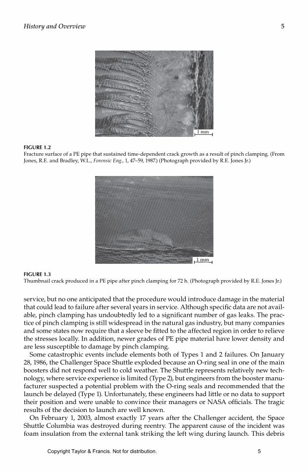
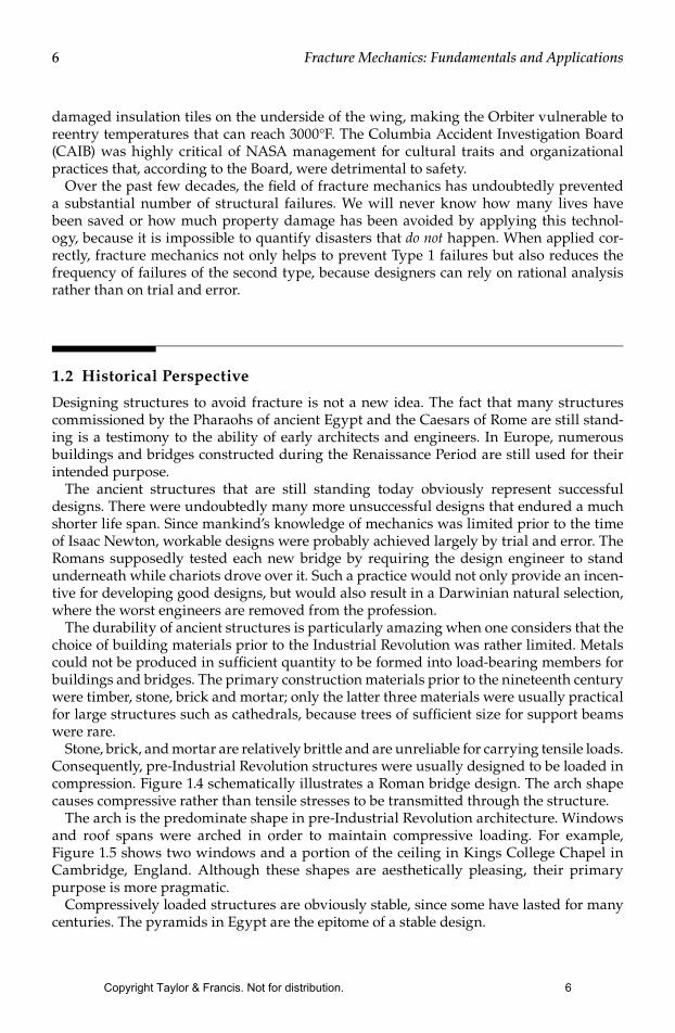