Embed Size (px)
Citation preview

NREL is a national laboratory of the U.S. Department of Energy, Office of Energy Efficiency & Renewable Energy, operated by the Alliance for Sustainable Energy, LLC.
Contract No. DE-AC36-08GO28308
Best Practices for Siting Solar Photovoltaics on Municipal Solid Waste Landfills A Study Prepared in Partnership with the Environmental Protection Agency for the RE-Powering America’s Land Initiative: Siting Renewable Energy on Potentially Contaminated Land and Mine Sites
Kosol Kiatreungwattana and Gail Mosey National Renewable Energy Laboratory
Shea Jones-Johnson and Craig Dufficy U.S. Environmental Protection Agency
Joe Bourg, Angela Conroy, Meghan Keenan, and William Michaud SRA
Katie Brown AAAS Science & Technology Fellow The National Renewable Energy Laboratory’s contribution was produced under direction of the U.S. Environmental Protection Agency (EPA) through Interagency Agreement IAG-09-1751 and Task No. WFD6.1001.
Technical Report NREL/TP-7A30-52615 February 2013

NREL is a national laboratory of the U.S. Department of Energy, Office of Energy Efficiency & Renewable Energy, operated by the Alliance for Sustainable Energy, LLC.
Contract No. DE-AC36-08GO28308
National Renewable Energy Laboratory 15013 Denver West Parkway Golden, CO 80401 303-275-3000 • www.nrel.gov
Best Practices for Siting Solar Photovoltaics on Municipal Solid Waste Landfills A Study Prepared in Partnership with the Environmental Protection Agency for the RE-Powering America’s Land Initiative: Siting Renewable Energy on Potentially Contaminated Land and Mine Sites
Kosol Kiatreungwattana and Gail Mosey National Renewable Energy Laboratory
Shea Jones-Johnson and Craig Dufficy U.S. Environmental Protection Agency
Joe Bourg, Angela Conroy, Meghan Keenan, and William Michaud SRA
Katie Brown AAAS Science & Technology Fellow The National Renewable Energy Laboratory’s contribution was produced under direction of the U.S. Environmental Protection Agency (EPA) through Interagency Agreement IAG-09-1751 and Task No. WFD6.1001.
Technical Report NREL/TP-7A30-52615 February 2013

NREL PUBLICATION NOTICE This manuscript has been authored, in part, by employees of the Alliance for Sustainable Energy, LLC (“Alliance”) under Contract No. DE-AC36-08GO28308 with the U.S. Department of Energy (“DOE”). This report was prepared as an account of work sponsored by an agency of the United States government. Neither the United States government nor any agency thereof, nor any of their employees, makes any warranty, express or implied, or assumes any legal liability or responsibility for the accuracy, completeness, or usefulness of any information, apparatus, product, or process disclosed, or represents that its use would not infringe privately owned rights. Reference herein to any specific commercial product, process, or service by trade name, trademark, manufacturer, or otherwise does not necessarily constitute or imply its endorsement, recommendation, or favoring by the United States government or any agency thereof. The views and opinions of authors expressed herein do not necessarily state or reflect those of the United States government or any agency thereof.
Cover Photos: (left to right) PIX 16416, PIX 17423, PIX 16560, PIX 17613, PIX 17436, PIX 17721
Printed on paper containing at least 50% wastepaper, including 10% post consumer waste.
Best Practices for Siting Solar Photovoltaics on Municipal Solid Waste Landfills
NREL/TP-7A30-52615

Best Practices for Siting Solar Photovoltaics on MSW Landfills February 2013
i
This document is a joint publication of the U.S. Environmental Protection Agency (EPA) and the National Renewable Energy Laboratory (NREL). NREL is a national laboratory of the U.S. Department of Energy, Office of Energy Efficiency and Renewable Energy, operated by the Alliance for Sustainable Energy, LLC.

Best Practices for Siting Solar Photovoltaics on MSW Landfills February 2013
ii
Contents 1. Introduction ................................................................................................................................................................ 1
1.1 Purpose and Audience for this Document ........................................................................................................... 2
1.2 Document Organization ....................................................................................................................................... 4
2. Landfill Overview ........................................................................................................................................................ 5
2.1 Background on Federal MSW Landfill Regulations ............................................................................................. 5
2.1.1 MSW Landfills .............................................................................................................................................. 5
2.2 Major System Components and Requirements ................................................................................................... 6
2.3 Closure and Post-Closure Care ........................................................................................................................... 7
3. Solar PV Overview ..................................................................................................................................................... 9
3.1 How PV Works ..................................................................................................................................................... 9
3.2 Major System Components................................................................................................................................ 10
3.2.1 PV Module .................................................................................................................................................. 10
3.2.1.1 Crystalline Silicon ................................................................................................................................. 10
3.2.1.2 Thin Film ............................................................................................................................................... 11
3.2.2 Inverter ....................................................................................................................................................... 11
3.2.3 Balance-of-System Components ................................................................................................................ 12
3.2.3.1 Mounting Systems ................................................................................................................................ 12
3.2.3.2 Wiring for Electrical Connections .......................................................................................................... 15
3.2.4 PV System Monitoring ................................................................................................................................ 15
3.3 Cost Overview ........................................................................................................................................................ 16
3.3.1 Cost Trends & General Rule of Thumb for PV Costing .............................................................................. 16
3.3.2 Cost per Watt Breakdown .......................................................................................................................... 16
4. Feasibility Considerations Unique to Landfills .......................................................................................................... 17
4.1 General Physical Setting ................................................................................................................................... 19
4.1.1 Meteorological Setting ................................................................................................................................ 19
4.1.2 Solar Resource Availability ......................................................................................................................... 20
4.1.3 Land Use and Ecological Conditions .......................................................................................................... 21
4.1.4 Transportation and Electrical Transmission Infrastructure ......................................................................... 21
4.2 Siting .................................................................................................................................................................. 21
4.2.1 Acreage of the Site ..................................................................................................................................... 21
4.2.2 Landfill Characteristics ............................................................................................................................... 22
4.2.2.1 Closure Status ...................................................................................................................................... 22
4.2.2.2 Cap Characteristics .............................................................................................................................. 23

Best Practices for Siting Solar Photovoltaics on MSW Landfills February 2013
iii
4.2.2.2.1 Type ................................................................................................................................................ 23
4.2.2.2.2 Age and Thickness ......................................................................................................................... 25
4.2.2.3 Slope and Stability ................................................................................................................................ 25
4.2.2.4 Settlement ............................................................................................................................................ 26
4.2.2.5 Erosion Control and Vegetative Cover ................................................................................................. 27
4.2.2.6 Control of Leachate and Landfill Gas ................................................................................................... 27
4.2.2.7 Stormwater Management ..................................................................................................................... 28
4.2.3 Institutional controls ................................................................................................................................... 28
4.2.4 Long term maintenance requirements ........................................................................................................ 29
4.3 PV Technology Selection and Technical Design ............................................................................................... 29
4.3.1 Matching Appropriate PV Technology to Landfill Characteristics ............................................................... 29
4.3.2 Conceptual Design of Major System Components ..................................................................................... 31
4.3.3 Energy Prediction ....................................................................................................................................... 32
4.3.4 Economic Considerations ........................................................................................................................... 32
4.4 Other Potential Feasibility Factors ..................................................................................................................... 32
4.4.1 Community Engagement & Support ........................................................................................................... 33
4.4.1.1 Benefits of Community Engagement .................................................................................................... 33
4.4.1.2 Openness and Transparency ............................................................................................................... 33
4.4.1.3 Facilitating Community Engagement .................................................................................................... 33
4.4.2 Visual Impacts and Mitigation Strategies ................................................................................................... 34
4.4.3 Interconnection ........................................................................................................................................... 34
4.4.4 Net Metering ............................................................................................................................................... 35
4.4.5 Virtual Net Metering ................................................................................................................................... 35
5. Design Considerations Unique to Building PV Projects on Landfills ....................................................................... 36
5.1 Landfill Characteristics ....................................................................................................................................... 36
5.1.1 Cap Characteristics .................................................................................................................................... 36
5.1.2 Waste Composition .................................................................................................................................... 37
5.1.2.1 Differential Settlement .......................................................................................................................... 37
5.1.2.1.1 Differential Settlement Forecasts .................................................................................................... 37
5.1.2.1.2 Differential Settlement – System Design Considerations ................................................................ 38
5.1.2.2 Landfill Gas and Leachate .................................................................................................................... 39
5.2 Anchoring Systems ............................................................................................................................................ 39
5.2.1 Shallow Poured Concrete Footers and Pre-fabricated Concrete Footers .................................................. 40
5.2.2 Concrete Slabs ........................................................................................................................................... 40
5.2.3 Augers or Helical Piles ............................................................................................................................... 41

Best Practices for Siting Solar Photovoltaics on MSW Landfills February 2013
iv
5.2.4 Ballasted Systems ...................................................................................................................................... 41
5.2.5 PV Integrated Geomembranes ................................................................................................................... 41
5.3 Mounting Systems ............................................................................................................................................. 42
5.3.1 Fixed-tilt Mounting Systems ....................................................................................................................... 43
5.3.2 PV Integrated Geomembranes ................................................................................................................... 44
5.4 Modules ............................................................................................................................................................. 44
5.4.1 Mono-crystalline ......................................................................................................................................... 44
5.4.2 Poly-crystalline ........................................................................................................................................... 44
5.4.3 Thin Film PV Products ................................................................................................................................ 45
5.5 System Weight Considerations .......................................................................................................................... 45
5.6 Stormwater Management................................................................................................................................... 46
5.7 Wind/Snow Loading and Frost Protection .......................................................................................................... 47
5.8 Lightning Protection and Grounding .................................................................................................................. 47
5.9 Cover Management ........................................................................................................................................... 47
5.10 Security ............................................................................................................................................................ 48
5.11 Integration with Landfill Gas Monitoring and Production Systems ................................................................... 48
5.12 PV System Engineering Design and Layout .................................................................................................... 49
6. Construction Considerations Unique to Building PV Projects on Landfills ............................................................... 50
6.1 Site Preparation and Grading Considerations ................................................................................................... 50
6.2 Site Compaction ................................................................................................................................................ 50
6.3 Penetrations of the Landfill Cap ......................................................................................................................... 51
6.4 Avoidance of Landfill Gas Monitoring, Piping, and Production Equipment ........................................................ 51
6.5 Dust Control ....................................................................................................................................................... 51
6.6 Stormwater Management................................................................................................................................... 52
6.7 Security .............................................................................................................................................................. 52
7. Operations and Maintenance Considerations for PV Projects on Landfills .............................................................. 53
7.1 Adherence with Landfill Post-Closure Operation, Maintenance, and Monitoring Plans ..................................... 53
7.2 Panel Washing and Water Management Plan or Natural Cleansing ................................................................. 53
7.3 Stormwater Management................................................................................................................................... 54
7.4 Vegetation and Cover Management .................................................................................................................. 54
7.5 System Monitoring and Troubleshooting ........................................................................................................... 54
7.6 System Security ................................................................................................................................................. 54
8. A Summary of Best Practices for Siting Solar PV Projects on Landfills ................................................................... 55
Appendix A: Solar PV on Landfill Projects ................................................................................................................. A-1

Best Practices for Siting Solar Photovoltaics on MSW Landfills February 2013
v
Appendix B: Tools and Resources ............................................................................................................................. B-1
EPA’s RE-Powering America’s Land Initiative, Renewable Energy Interactive Mapping Tool .............................. B-1
Siting Renewable Energy on Contaminated Properties: Addressing Liability Concerns Fact Sheet ..................... B-2
NREL System Advisor Model ................................................................................................................................ B-2
NREL PV Watts ..................................................................................................................................................... B-4
Solar Decision Tree ............................................................................................................................................... B-6
Appendix C: Financing and Procurement Options ..................................................................................................... C-1
Owner and Operator Financing ............................................................................................................................. C-1
Third Party Developers with Power Purchase Agreements (PPA) ......................................................................... C-1
Third Party “Flip” Agreements ................................................................................................................................ C-1
Hybrid Financial Structures .................................................................................................................................... C-2
Solar Services Agreement and Operating Lease ................................................................................................... C-2
Sale/Lease Back .................................................................................................................................................... C-2
Community Solar Gardens .................................................................................................................................... C-2
Appendix D: References ............................................................................................................................................ D-1
List of Figures Figure 1-1: Sample conceptual design of solar PV on a closed landfill .......................................................................... 2
Figure 2-1: Typical MSW landfill components ................................................................................................................ 7
Figure 3-1: Generation of electricity from a PV cell ........................................................................................................ 9
Figure 3-2: Ground mount array diagram ..................................................................................................................... 10
Figure 3-3: Mono- and multi-crystalline solar modules ................................................................................................. 11
Figure 3.4: Thin-film solar modules installed on (i) solar energy cover and (ii/iii) fixed tilt mounting systems .............. 11
Figure 3-5: String inverter ............................................................................................................................................ 12
Figure 3-6: 2-MWp PV system with fixed tilt on former landfill in Fort Carson, Colorado ............................................. 14
Figure 3-7: PV system with single-axis trackers installed on former landfill at Nellis Air Force Base, Nevada ............ 14
Figure 3-8: PV system with dual-axis trackers ............................................................................................................. 15
Figure 3-9: Average PV system cost from Q1 2010 to Q2 2011 .................................................................................. 16
Figure 3-10: Cost contributions of PV system components ......................................................................................... 16
Figure 4-1: MSW landfill and PV technology as an integrated system ......................................................................... 18
Figure 4-2: Photovoltaic solar resource ....................................................................................................................... 20
Figure 4-3: Possible cover systems ............................................................................................................................. 23
Figure 4-4: Example of an alternative final cover design ............................................................................................. 24
Figure 4-5: Sample solar PV and landfill integrated system design ............................................................................. 30

Best Practices for Siting Solar Photovoltaics on MSW Landfills February 2013
vi
Figure 5-1: Precast ballast foundation for fixed tilt PV on a landfill .............................................................................. 40
Figure 5-2: Slab foundation for PV system at Boulder, Colorado ................................................................................. 40
Figure 5-3: Ballasted anchoring system at Landfill 1A project at New Jersey Meadowlands ....................................... 41
Figure 5-4: Hickory Ridge Road Landfill – Geomembrane solar cover ........................................................................ 42
Figure B-1: Google Earth Interactive Mapping Tool ................................................................................................... B-1
Figure B-2: SAM block diagram ................................................................................................................................. B-2
Figure B-3: PV system inputs ..................................................................................................................................... B-3
Figure B-4: Sample of SAM simulation results ........................................................................................................... B-4
Figure B-5: Example of input and output of PVWatts ................................................................................................. B-5
Figure B-6: Solar Decision Tree ................................................................................................................................. B-6
List of Tables Table 4-1: Technical and Economic Factors Impacting Solar Project Feasibility on Landfills ...................................... 18
Table 4-2: Energy Density by Module and System Type for Ground-mounted PV ...................................................... 32
Table 5-1: Inter-relationships Between Landfill Cap Characteristics and PV System Design ...................................... 36
Table 8-1: Summary of Technical Considerations, Challenges, and Best Practices .................................................... 55
Table A-1: Completed Solar Landfill Projects ............................................................................................................. A-1
List of Highlights Highlight 2-1: Trends in MSW Landfill Ownership .......................................................................................................... 5
Highlight 4-1: Solar Geomembrane Covers for Landfill Applications ........................................................................... 22
Highlight 4-2: Examples of Community Engagement ................................................................................................... 33
Highlight 5-1: Major Considerations Impacting Solar PV Project Design on Landfills .................................................. 36
Highlight 6-1: Major Construction Considerations for Building PV Projects on Landfills ............................................. 50
Highlight 7-1: Major Considerations and Best Practices ............................................................................................. 53
Best Practices for Siting Solar Photovoltaics on MSW Landfills February 2013
1
1. Introduction Through the RE-Powering America’s Lands Initiative1, the U.S. EPA promotes the reuse of potentially contaminated properties, landfills, and mining sites for renewable energy generation. EPA has identified several benefits for siting solar photovoltaics (PV) facilities on potentially contaminated lands and municipal solid waste (MSW) landfills, noting that these sites:
• May provide an economically viable reuse for sites that may have significant cleanup costs or low real estate development demand;
• May have environmental conditions that are not well suited for commercial or residential redevelopment;
• Can be developed in place of limited open space, preserving the land as a carbon sink and/or for other ecosystem services;
• Generally are located near existing roads and energy transmission or distribution infrastructure;
• May be adequately zoned for renewable energy;
• Can provide job opportunities in urban and rural communities;
• Can advance cleaner and more cost effective energy technologies; and
• May reduce the environmental impacts of energy systems (e.g., reduce greenhouse gas emissions). 2 EPA has screened more than 11,000 potentially contaminated sites and MSW landfills3 — covering nearly 15 million acres across the United States — for suitability to site renewable energy generation facilities, including utility-scale solar. Maps depicting the locations of these EPA tracked sites and their potential for supporting renewable energy generation can be found at: www.epa.gov/oswercpa/mapping_tool.htm. These maps enable users to view screening results for various renewable energy technologies at each site. In 1988, before municipal solid waste regulations in 40 CFR 258 were promulgated, there were an estimated 7,924 landfills in the U.S. In 2009, that number dropped to 1,908 landfills. The landfills that closed over the intervening years—plus portions of active landfills with closed cells—represent thousands of acres of real property that may be suitable for siting solar PV. At least one study estimates the area of closed landfills to be hundreds of thousands of acres. As part of the EPA mapping effort, over 1,600 of the country’s landfills have been pre-screened for renewable energy potential. Many MSW landfills are particularly well-suited for solar development because they are often:
• Located near critical infrastructure including electric transmission lines and roads;
• Located near areas with high energy demand (e.g., large population bases);
• Constructed with large areas of minimal grade (0-2 percent) needed for optimal siting of solar photovoltaic (PV) structures;
• Offered at lower land costs when compared to open space; and
• Able to accommodate net metered or utility scale projects.
1 EPA OSWER Center for Program Analysis. Siting Clean and Renewable Energy on Contaminated Lands and Mining Sites. Factsheet. Undated. 2 EPA. RE-Powering America’s Land: Siting Renewable Energy on Potentially Contaminated Land and Mine Sites. Anywhere the Sun Shines: Developing Solar
Energy on Contaminated Land. October 2009. 3 The Landfill Methane Outreach Program (LMOP) maintains a list of MSW landfills which are candidates for landfill gas (LFG) projects, have potential for LFG,
LFG systems under construction, operational LFG or shutdown LFG facilities. This program is a voluntary assistance and partnership program that promotes the use of landfill gas as a renewable, green energy resource. These landfills were mapped as part of the RE-Powering initiative to show landfills which could be developed for LFG and solar PV renewable energy. Visit EPA’s LMOP website at www.epa.gov/lmop/ for more information on landfill gas energy projects.

Best Practices for Siting Solar Photovoltaics on MSW Landfills February 2013
2
Source: PV Navigator
Figure 1-1: Sample conceptual design of solar PV on a closed landfill4
1.1 Purpose and Audience for this Document
This document is a joint publication of EPA and the National Renewable Energy Laboratory (NREL). EPA and NREL created this document to provide assistance in addressing common technical challenges for siting PV on MSW landfills, and in this respect EPA and NREL expect that stakeholders, such as solar developers, landfill owners, and federal, state, and local governments, may find this information useful. The information in this document is primarily targeted toward a technical audience geared toward the functional integration of a PV system and the engineered systems typically at MSW landfills. This document focuses on MSW landfills, including but not limited to those that are regulated under EPA’s Resource Conservation and Recovery Act (RCRA) regulations at 40 CFR Part 258. However, it may be determined on a site-by-site basis if this information may be useful for siting PV solar on other types of landfills such as those that are exempt from 40 CFR Part 258 and hazardous waste landfills. Note that MSW landfills are subject to varying regulatory requirements, under RCRA and other authorities at the federal, state, and/or
4 This figure has been modified from the original PV Navigator file for the use of this report

Best Practices for Siting Solar Photovoltaics on MSW Landfills February 2013
3
local level. Therefore, this document does not attempt to apply the best practices discussed to a particular regulatory context, and the strategies discussed may or may not be available at a particular site.5 Currently, there are only a handful of completed PV projects on landfills throughout the country, with many more in the planning stages (see Appendix A for a list of identified projects). EPA and NREL, along with our state and local partners, have examined many of these projects and reviewed current designs and approaches in an ongoing effort to identify best practices for siting PV on MSW landfills. The data and case studies contained in this document reflect current engineering and scientific practices. Furthermore, this is not an exhaustive list of best practices. Project stakeholders should consider whether different or additional approaches are appropriate in light of site specific conditions.
5 This document does not address what activities associated with siting solar PV may be appropriate on landfills that may be subject to cleanup actions taken
pursuant to CERCLA and/or RCRA Corrective Action. Further, this document is not intended to discuss CERCLA liability considerations. For more information on the EPA’s cleanup enforcement programs, see http://www.epa.gov/enforcement/waste/index.html#Cleanup.
Disclaimer This document provides general information and guidance regarding siting solar PV facilities on MSW landfills. It does not address all information, factors, or considerations that may be relevant in a particular situation. This document is not legally binding. The word “should” and other similar terms used in this document are intended as general recommendations or suggestions that might be generally applicable or appropriate and should not be taken as providing legal, technical, financial, or other advice regarding a specific situation or set of circumstances. This document describes and summarizes statutory provisions, regulatory requirements, and policies. The document is not a substitute for these provisions, regulations, or policies, nor is it a regulation itself. In the event of a conflict between the discussion in this document and any statute, regulation, or policy, this document would not be controlling and cannot be relied upon to contradict or argue against any EPA position taken administratively or in court. It does not impose legally binding requirements on EPA or the regulated community, and might not be applicable in a particular situation based upon the specific circumstances. This document does not modify or supersede any existing EPA guidance document or affect the Agency’s enforcement discretion in any way. References to third-party publications, websites, commercial products, process, or services by trade name, trademark, manufacturer, or otherwise, are for informational purposes only. No endorsement or recommendation should be inferred and is not implied. EPA, NREL and the United States Government do not endorse any non-federal product, service or enterprise.

Best Practices for Siting Solar Photovoltaics on MSW Landfills February 2013
4
1.2 Document Organization The document is organized into eight major chapters: Chapter 1. Provides a brief overview of the document. Chapter 2. Landfill Overview: Discusses waste disposal practices in the U.S., benefits for siting solar technologies on MSW landfills, and typical landfill components. Chapter 3. PV Overview: Describes the types of PV technology currently sited on landfills and provides a brief overview for typical PV system components, and outlines estimated costs for PV technologies currently sited on landfills, including installation costs. Chapter 4. Feasibility Considerations Unique to Landfills: Provides a detailed discussion on the decision-grade feasibility assessment process with a focus on the unique considerations (e.g., siting, technology selection) that should be taken into account when planning for PV system development on a landfill. Chapter 5. Design Considerations Unique to Building PV Projects on Landfills: Outlines landfill characteristics to be taken into account when designing a solar project on a landfill, PV system layout and component system designs, and considerations regarding the integrated PV-landfill system. Chapter 6. Construction Considerations Unique to Building PV Projects on Landfills: Discusses site preparation, grading, site compaction, working around landfill features, and other site-specific aspects that should be considered before starting construction of a PV system on a landfill. Chapter 7. Operations and Maintenance Considerations for PV Projects on Landfills: Outlines the types of longer term actions (e.g., adherence with post-closure plans, water management, module cleaning) that should be taken to ensure continued safe and effective operation of the PV system once it is established. Chapter 8. A Summary of Best Practices for Siting Solar PV Projects on Landfills: Summarizes the best practices for siting solar PV projects on landfills as discussed throughout the document. This document also contains the following appendices: Appendix A. List of Completed Solar PV on Landfill Projects Appendix B. Tools and Resources Appendix C. Financing and Procurement Options Appendix D. References
Best Practices for Siting Solar Photovoltaics on MSW Landfills February 2013
5
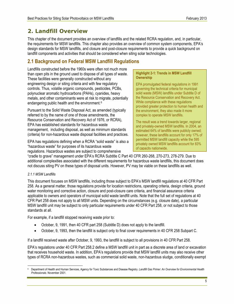
Highlight 2-1: Trends in MSW Landfill Ownership EPA promulgated federal regulations in 1991 governing the technical criteria for municipal solid waste (MSW) landfills under Subtitle D of the Resource Conservation and Recovery Act. While compliance with these regulations provided greater protection to human health and the environment, they also made it more complex to operate MSW landfills.
The result was a trend towards larger, regional and privately-owned MSW landfills. In 2004, an estimated 64% of landfills were publicly owned; however, these landfills account for only 17% of permitted MSW landfill capacity while the 595 privately owned MSW landfills account for 83% of capacity nationwide.
2. Landfill Overview This chapter of the document provides an overview of landfills and the related RCRA regulation, and, in particular, the requirements for MSW landfills. This chapter also provides an overview of common system components, EPA’s design standards for MSW landfills, and closure and post-closure requirements to provide a quick background on landfill components and activities that should be considered when siting solar technologies.
2.1 Background on Federal MSW Landfill Regulations Landfills constructed before the 1960s were often not much more than open pits in the ground used to dispose of all types of waste. These facilities were generally constructed without any engineering design or siting criteria and with few regulatory controls. Thus, volatile organic compounds, pesticides, PCBs, polynuclear aromatic hydrocarbons (PAHs), cyanides, heavy metals, and other contaminants were at risk to migrate, potentially endangering public health and the environment.6 Pursuant to the Solid Waste Disposal Act, as amended (typically referred to by the name of one of those amendments, the Resource Conservation and Recovery Act of 1976, or RCRA), EPA has established standards for hazardous waste management, including disposal, as well as minimum standards (criteria) for non-hazardous waste disposal facilities and practices. EPA has regulations defining when a RCRA “solid waste” is also a “hazardous waste” for purposes of its hazardous waste regulations. Hazardous wastes are subject to comprehensive “cradle to grave” management under EPA’s RCRA Subtitle C Part 40 CFR 260-268, 270-273, 278-279. Due to additional complexities associated with the different requirements for hazardous waste landfills, this document does not discuss siting PV on these types of disposal units. However, PV may be viable on these landfills as well.
2.1.1 MSW Landfills
This document focuses on MSW landfills, including those subject to EPA’s MSW landfill regulations at 40 CFR Part 258. As a general matter, those regulations provide for location restrictions, operating criteria, design criteria, ground water monitoring and corrective action, closure and post-closure care criteria, and financial assurance criteria applicable to owners and operators of municipal solid waste landfill units. Note that the full set of regulations at 40 CFR Part 258 does not apply to all MSW units. Depending on the circumstances (e.g. closure date), a particular MSW landfill unit may be subject to only particular requirements under 40 CFR Part 258, or not subject to those standards at all. For example, if a landfill stopped receiving waste prior to:
• October, 9, 1991, then 40 CFR part 258 (Subtitle D) does not apply to the landfill. • October, 9, 1993, then the landfill is subject only to final cover requirements in 40 CFR 258 Subpart C.
If a landfill received waste after October, 9, 1993, the landfill is subject to all provisions in 40 CFR Part 258. EPA’s regulations under 40 CFR Part 258.2 define a MSW landfill unit in part as a discrete area of land or excavation that receives household waste. In addition, EPA’s regulations provide that MSW landfill units may also receive other types of RCRA non-hazardous wastes, such as commercial solid waste, non-hazardous sludge, conditionally exempt
6 Department of Health and Human Services, Agency for Toxic Substances and Disease Registry. Landfill Gas Primer: An Overview for Environmental Health
Professionals. November 2001.
Best Practices for Siting Solar Photovoltaics on MSW Landfills February 2013
6
small quantity generator (CESQG) waste, and industrial solid waste. Note that the management of non-hazardous waste is not necessarily without risk even if classified as non-hazardous waste under the RCRA regulations. Under RCRA, states are to adopt and implement permit programs or other systems of prior approval to ensure that MSW landfills comply with the relevant federal criteria. RCRA requires that EPA determine whether state permit programs are adequate to ensure such compliance. EPA continues to monitor state permitting programs and maintains a list of approved states.7 EPA’s criteria for MSW landfill units apply regardless of whether the unit is in an approved state or not. However, owners and operators in approved states have more flexibility in how they comply with the federal standards. Note that some states may impose additional requirements that are more stringent or broader in scope than the federal requirements. Finally, note that requirements under other federal, state or local authorities may apply to a particular MSW landfill. Developers must work closely with state and local regulators to ensure compliance with applicable regulatory requirements.
2.2 Major System Components and Requirements Federal landfill regulations include requirements for specific features and specific practices. Depending on the date when the landfill started accepting waste, federal RCRA regulations for MSW landfills may include requirements for:
• Location – Location restrictions include proximity to airports, floodplains, wetlands, unstable areas, fault areas, and seismic impact zones.
• Design – These requirements may include: o A composite liner comprised of a flexible membrane (geomembrane) overlaying two feet of
compacted soil lining the bottom and sides of the landfill. A landfill liner serves to protect ground water and the underlying soil from leachate releases.
o A leachate collection and removal system. These are generally located on top of the composite liner to remove leachate from the landfill for treatment and disposal.
• Operating practices – These include covering waste frequently with soil or other materials to control odor, blowing litter, fires, disease vectors, such as insects and rodents; and scavenging. Also, owners/operators must implement a program for detecting and preventing the disposal of regulated hazardous waste. See 40 CFR 258.20(a).
• Ground water monitoring and corrective action – These include installation and testing of ground water wells to detect and assess ground water contamination, and establishment of necessary corrective measures for identified releases.
• Closure and post-closure care – These include installation of a final landfill cover and providing long-term care of closed landfills.8
Under the Clean Air Act, a landfill gas collection system is required on landfills with a design capacity greater than 2.5 million megagrams (Mg), and with an emission greater than 50 Mg/year of non-methane organic compounds as defined by the US EPA new source performance standards (NSPS) and emission guidelines (40 CFR 60.752). 9 Figure 2-1 shows common MSW landfill components.
7 Approved state means a state whose Subtitle D permit program or other system of prior approval and conditions required under section 4005(c)(1)(B) of
RCRA has been determined to be adequate by EPA, as defined in 40 CFR 239. 8 Waste – Non-Hazardous Waste – Municipal Solid Waste.” EPA. Accessed April 22, 2012: http://www.epa.gov/osw/nonhaz/municipal/landfill.htm. 9 EPA’s New Source Performance Standards for MSW Landfills (NSPS) prescribe a landfill surface emissions monitoring methodology that relies on
identification of discrete exceedances of a 500 ppm methane standard. After the installation of extraction wells, the landfill surface must be monitored for methane concentrations less than 500 ppm above background levels. If an exceedance is detected, corrective action must be taken by performing cover maintenance or adjusting the collection system operating parameters (40 CFR 60 Subpart).

Best Practices for Siting Solar Photovoltaics on MSW Landfills February 2013
7
Source: EPA
Figure 2-1: Typical MSW landfill components10
EPA encourages all parties to fully examine federal, state, and local standards before undertaking solar planning and construction activities on a landfill. Overall, PV systems sited at landfills should be integrated with, and designed with careful attention to, these regulatory requirements.
2.3 Closure and Post-Closure Care Once a landfill has been filled, it must be closed according to applicable regulations. Under EPA’s MSW landfill regulations, the applicability of closure and post-closure requirements varies depending upon a number of considerations, including date of final receipt of waste, volume of waste disposed of, and other considerations. State, local, and/or tribal law requirements may also apply to the closure and post-closure processes. Under EPA’s MSW landfill regulations, owners or operators, where applicable, are required to install a final cover on the unit as part of the closure process. The regulations specify design parameters, although the director of an approved state may approve an alternative design. The regulations also specify timeframes for closure generally after receiving its final shipment of waste, a unit must begin closure operations within 30 days, although an owner or operator may delay closure for up to one year if additional capacity remains and there is a reasonable likelihood that the unit will receive additional wastes. Any further delays after one year require approval from the director of an approved state. All closure activities must be completed within 180 days of beginning closure (with the exception of an extension from the director of an approved state), and the owner/operators must certify that the closure has been completed in accordance with the closure plan, and must place the certification in the operating record. Technical issues that are typically addressed during closure include the following:
• Degree and rate of post-closure settlement and stresses imposed on soil liner components;
• Long-term durability and survivability of cover system;
• Long-term waste decomposition and management of landfill leachate and gases; and
• Environmental performance of the combined bottom liner and final cover system.
10 Adapted from RCRA Orientation Manual 2008: Resource Conservation and Recovery Act. (2008). EPA. p II-11.
Explosive Gas Monitoring Well
Gas Vent
Leachate Collection
Liner Ground Water Monitoring Well
Waste

Best Practices for Siting Solar Photovoltaics on MSW Landfills February 2013
8
EPA’s MSW landfill regulations also generally provide that for 30 years11 after closure, the owner/operator is responsible for conducting post-closure care. Activities required during post-closure care can include:
• Maintaining the integrity and effectiveness of any final cover;
• Maintaining and operating the leachate collection system;
• Monitoring ground water; and
• Maintaining and operating the gas monitoring system The regulations specify that any use of the land during the post-closure period must not disturb the integrity of the waste containment systems or the functioning of the monitoring systems, except in specified circumstances as provided in 40 CFR 258 Subpart F. In addition, the owner or operator must prepare a written post-closure plan, and include within it a description of planned uses during the post-closure care period. At the end of the post-closure care period, the owner/operator must certify that the post-closure care has been completed in accordance with the post-closure care plan and must place the certification in the operating record. Any solar project development activities on closed landfills must be planned to take into account these closure and post-closure activities and requirements. To do so, all solar projects on MSW landfills must be coordinated closely with state and local authorities, as they are mainly responsible for ensuring that these requirements and other state law requirements are met.
11 Approved states may vary this interval. In addition, states and local authorities may approve the use of alternative final covers and grant extensions for
beginning and ending closure activities.

Best Practices for Siting Solar Photovoltaics on MSW Landfills February 2013
9
3. Solar PV Overview
3.1 How PV Works Solar PV technology converts energy from solar radiation directly into electricity. Solar PV cells are the electricity-generating component of a solar energy system. When sunlight (photons) strikes a PV cell, an electric current is produced by stimulating electrons (negative charges) in a layer in the cell designed to give up electrons easily. The existing electric field in the solar cell pulls these electrons to another layer. By connecting the cell to an external load, this current (movement of charges) can then be used to power the load, e.g., light bulb.
(-)(+)
-
- -
-Electron
Current flow
-
Solar cell
- - -
Load
Source: EPA
Figure 3-1: Generation of electricity from a PV cell
PV cells are assembled into a PV panel or module. PV modules are then connected to create an array. The modules are connected in series and then in parallel as needed to reach the specific voltage and current requirements for the array. The direct current (DC) electricity generated by the array is then converted by an inverter to useable alternating current (AC) that can be consumed by adjoining buildings and facilities or exported to the electricity grid. PV system size varies from small residential (2-10 kilowatts (kW)), commercial (100-500 kW), to large utility scale (10+ megawatts (MW)). Central distribution plants are also currently being built on the 100 MW+ scale. Electricity from utility-scale systems, such as solar on landfills, is commonly sold back to the electricity grid.

Best Practices for Siting Solar Photovoltaics on MSW Landfills February 2013
10
3.2 Major System Components
Source: NREL
Figure 3-2: Ground mount array diagram
A typical PV system is made up of several key components including:
• PV modules
• Inverter
• Balance-of-system components These, along with other PV system components, are discussed in turn below.
3.2.1 PV Module
Module technologies are differentiated by the type of PV material used, resulting in a range of conversion efficiencies from light energy to electrical energy. The module efficiency is a measure of the percentage of solar energy converted into electricity. Two common PV technologies that have been widely used for commercial- and utility-scale projects are crystalline silicon and thin film. Additional PV technologies are also commercially available, but are not covered in this document. 3.2.1.1 Crystalline Silicon
Traditional solar cells are made from silicon. Silicon is quite abundant and nontoxic. It builds on a strong industry from both the supply (silicon industry) and product side. This technology has been demonstrated as a consistent and high efficiency technology over 30 years in the field. The performance degradation, a reduction in power generation due to long-term exposure, is under 1 percent per year. Silicon modules have typical power-production warranties in the 25-30-year range but can continue producing energy beyond this timeframe.
Best Practices for Siting Solar Photovoltaics on MSW Landfills February 2013
11
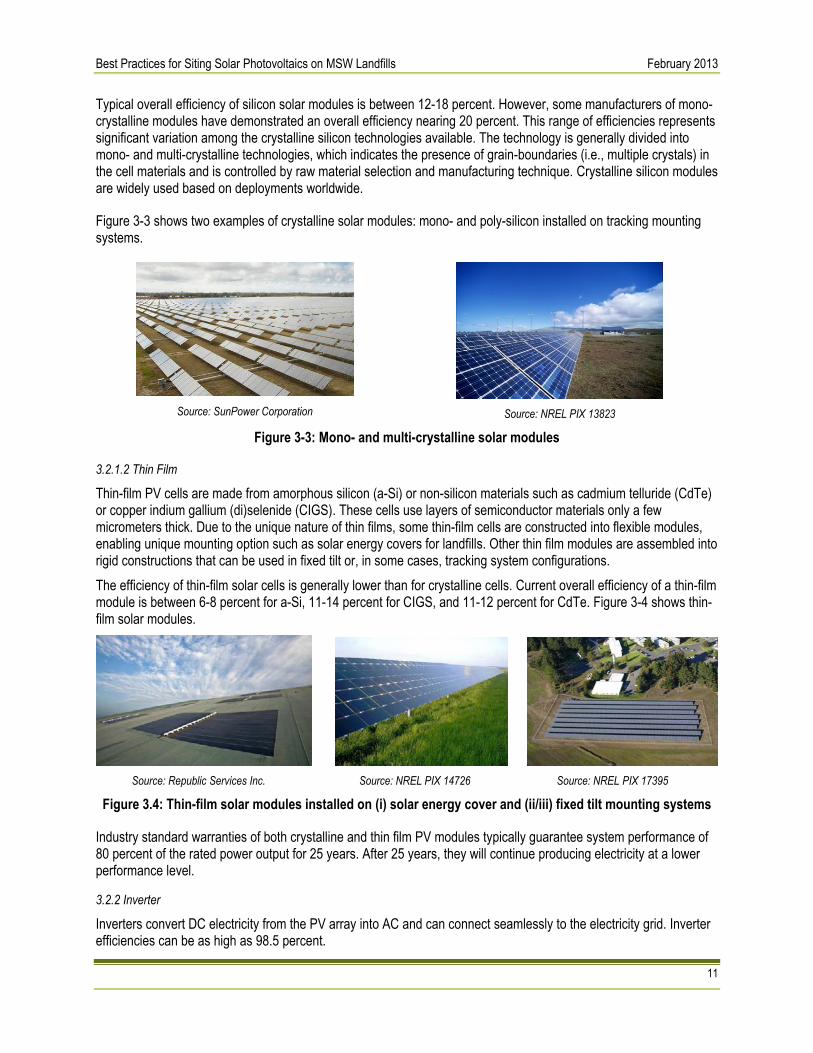
Typical overall efficiency of silicon solar modules is between 12-18 percent. However, some manufacturers of mono-crystalline modules have demonstrated an overall efficiency nearing 20 percent. This range of efficiencies represents significant variation among the crystalline silicon technologies available. The technology is generally divided into mono- and multi-crystalline technologies, which indicates the presence of grain-boundaries (i.e., multiple crystals) in the cell materials and is controlled by raw material selection and manufacturing technique. Crystalline silicon modules are widely used based on deployments worldwide.
Figure 3-3 shows two examples of crystalline solar modules: mono- and poly-silicon installed on tracking mounting systems.
Source: SunPower Corporation
Source: NREL PIX 13823
Figure 3-3: Mono- and multi-crystalline solar modules
3.2.1.2 Thin Film
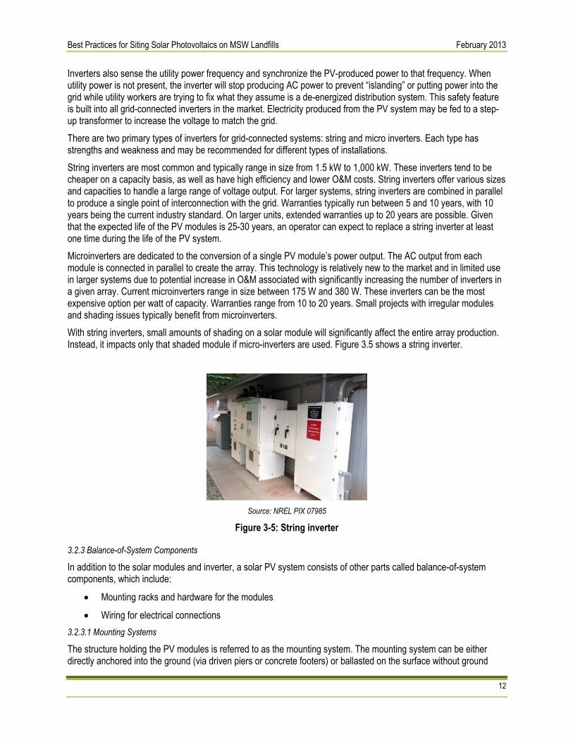
Thin-film PV cells are made from amorphous silicon (a-Si) or non-silicon materials such as cadmium telluride (CdTe) or copper indium gallium (di)selenide (CIGS). These cells use layers of semiconductor materials only a few micrometers thick. Due to the unique nature of thin films, some thin-film cells are constructed into flexible modules, enabling unique mounting option such as solar energy covers for landfills. Other thin film modules are assembled into rigid constructions that can be used in fixed tilt or, in some cases, tracking system configurations. The efficiency of thin-film solar cells is generally lower than for crystalline cells. Current overall efficiency of a thin-film module is between 6-8 percent for a-Si, 11-14 percent for CIGS, and 11-12 percent for CdTe. Figure 3-4 shows thin-film solar modules.
Source: Republic Services Inc. Source: NREL PIX 14726 Source: NREL PIX 17395
Figure 3.4: Thin-film solar modules installed on (i) solar energy cover and (ii/iii) fixed tilt mounting systems
Industry standard warranties of both crystalline and thin film PV modules typically guarantee system performance of 80 percent of the rated power output for 25 years. After 25 years, they will continue producing electricity at a lower performance level.
3.2.2 Inverter
Inverters convert DC electricity from the PV array into AC and can connect seamlessly to the electricity grid. Inverter efficiencies can be as high as 98.5 percent.
Best Practices for Siting Solar Photovoltaics on MSW Landfills February 2013
12
Inverters also sense the utility power frequency and synchronize the PV-produced power to that frequency. When utility power is not present, the inverter will stop producing AC power to prevent “islanding” or putting power into the grid while utility workers are trying to fix what they assume is a de-energized distribution system. This safety feature is built into all grid-connected inverters in the market. Electricity produced from the PV system may be fed to a step-up transformer to increase the voltage to match the grid. There are two primary types of inverters for grid-connected systems: string and micro inverters. Each type has strengths and weakness and may be recommended for different types of installations. String inverters are most common and typically range in size from 1.5 kW to 1,000 kW. These inverters tend to be cheaper on a capacity basis, as well as have high efficiency and lower O&M costs. String inverters offer various sizes and capacities to handle a large range of voltage output. For larger systems, string inverters are combined in parallel to produce a single point of interconnection with the grid. Warranties typically run between 5 and 10 years, with 10 years being the current industry standard. On larger units, extended warranties up to 20 years are possible. Given that the expected life of the PV modules is 25-30 years, an operator can expect to replace a string inverter at least one time during the life of the PV system. Microinverters are dedicated to the conversion of a single PV module’s power output. The AC output from each module is connected in parallel to create the array. This technology is relatively new to the market and in limited use in larger systems due to potential increase in O&M associated with significantly increasing the number of inverters in a given array. Current microinverters range in size between 175 W and 380 W. These inverters can be the most expensive option per watt of capacity. Warranties range from 10 to 20 years. Small projects with irregular modules and shading issues typically benefit from microinverters. With string inverters, small amounts of shading on a solar module will significantly affect the entire array production. Instead, it impacts only that shaded module if micro-inverters are used. Figure 3.5 shows a string inverter.
Source: NREL PIX 07985
Figure 3-5: String inverter
3.2.3 Balance-of-System Components
In addition to the solar modules and inverter, a solar PV system consists of other parts called balance-of-system components, which include:
• Mounting racks and hardware for the modules
• Wiring for electrical connections 3.2.3.1 Mounting Systems
The structure holding the PV modules is referred to as the mounting system. The mounting system can be either directly anchored into the ground (via driven piers or concrete footers) or ballasted on the surface without ground

Best Practices for Siting Solar Photovoltaics on MSW Landfills February 2013
13
penetration. Mounting systems should be selected and designed to withstand local wind loads, which range from 90–120 mph range for most areas or 130 mph or more for areas with hurricane potential. Depending on the region, snow and ice loads should also be design considerations for the mounting system. For landfill applications, mounting system designs will be primarily driven by these considerations coupled with settlement concerns. More details on settlement and anchoring systems can be found can be found in Sections 4.2.2.4 and 5.2, respectively. Typical ground-mounted systems can be categorized as fixed tilt or tracking. Fixed-tilt mounting systems are characterized by modules installed at a set angle, typically based on site latitude and wind conditions, to increase exposure to solar radiation throughout the year. Fixed-tilt systems are used at many landfill sites. Fixed-tilt systems may have lower maintenance costs but generate less energy (kWh) per unit power (kW) of capacity than tracking systems (Figure 3-6). Tracking systems rotate the PV modules so they are following the sun as it moves across the sky. This increases energy output but also may increase maintenance and equipment costs slightly. Single-axis tracking, in which PV is rotated on a single axis, can increase energy output up to 25 percent or more (Figure 3-7). With dual-axis tracking, PV is able to directly face the sun all day, potentially increasing output up to 35 percent or more. Due to alignment requirements of the mounting system, single- and dual-axis trackers are not generally deployed on landfill cells, as discussed below. Tracking systems may be more appropriate for landfill buffer zones when permitted, since settlement concerns are typically less significant. The selection of mounting type is dependent on many factors including installation size, electricity rates, government incentives, land constraints, latitude, and local weather. Landfill applications raise additional design considerations due to differential settlement, which can impact both structural integrity and energy generation of the PV system. Mitigation for settlement effects should be taken into account in the design of both fixed tilt and tracking systems. Impacts on energy performance may be more severe for tracking systems due to alignment requirements. Depending on the degree of predicted settlement, fixed tilt systems may be preferable, while trackers may be sited primarily in buffer areas around the closed landfill cell when permitted. In addition, all of the PV systems need to take into account the landfill monitoring operations and ongoing site conditions noted in Chapters 2.2 and 2.3. Selection of the mounting system is also heavily dependent on anchoring or foundation selection. The mounting system design will also need to meet applicable local building code requirements with respect to snow, wind, and earthquake factors. Selection of mounting types should also consider frost protection needs especially in cold regions, such as New England. This topic is covered in additional detail in Chapter 5.2 and 5.3, including site-specific considerations for landfill applications.

Best Practices for Siting Solar Photovoltaics on MSW Landfills February 2013
14
Source: NREL PIX 17394
Figure 3-6: 2-MWp PV system with fixed tilt on former landfill in Fort Carson, Colorado
Source: NREL PIX 15280
Figure 3-7: PV system with single-axis trackers installed on former landfill at Nellis Air Force Base, Nevada

Best Practices for Siting Solar Photovoltaics on MSW Landfills February 2013
15
Source: NREL PIX 04827
Figure 3-8: PV system with dual-axis trackers
3.2.3.2 Wiring for Electrical Connections
Electrical connections, including wiring, disconnect switches, fuses, and breakers are required to meet electrical code (e.g., NEC Article 690) for both safety and equipment protection. In most traditional applications, wiring from (i) the arrays to inverters and (ii) inverters to point of interconnection is generally run as direct burial through trenches. In landfill applications, this wiring may be required to run through above-ground conduit due to restrictions with cap penetration or other concerns. Therefore, landfill owners or operators should disclose any such restrictions, if applicable. Similarly, it is recommended that developers reflect these costs in the quote when costing out the overall system.
3.2.4 PV System Monitoring
Monitoring PV systems can be essential for reliable functioning and maximum yield of a system. It can be as simple as reading values such as produced AC power, daily kilowatt-hours, and cumulative kilowatt-hours locally on an LCD display on the inverter. For more sophisticated monitoring and control purposes, environmental data such as module temperature, ambient temperature, solar radiation, and wind speed can be collected. Remote control and monitoring can be performed by various remote connections. Systems can send alerts and status messages to the control center or user. Data can be stored in the inverter’s memory or in external data loggers for further system analysis. Collection of this basic information is standard for solar systems and not unique to landfill applications. Weather stations are typically installed at large scale systems. Weather data such as solar radiation and temperature can be used to predict energy production, enabling comparison of the target and actual system output and performance and identification of under-performing arrays. Operators may also use this data to identify required maintenance, shade on modules, accumulated soiling on modules, etc. Monitoring system data can also be used for outreach and education. This can be achieved with publicly available, online displays; wall-mounted systems; or even smart phone applications.

Best Practices for Siting Solar Photovoltaics on MSW Landfills February 2013
16
3.3 Cost Overview 3.3.1 Cost Trends & General Rule of Thumb for PV Costing
The cost of a PV system depends on the system size and other factors such as geographic location, mounting system, type of PV module, among others. Based on significant cost reductions seen in 2011, the average cost for utility-scale ground mounted systems have declined from $4.80 per watt in Q1 2010 to $3.75 per watt in Q2 2011. With a growing market and an increasing supply, further cost reduction is expected as market conditions evolve. Figure 3-9 shows the cost per watt of PV system from 2010 to 2011 for utility scale projects.
Source: U.S. Solar Market Insight 2nd Quarter 2011, Solar Energy Industries Association
Figure 3-9: Average PV system cost from Q1 2010 to Q2 201112
3.3.2 Cost per Watt Breakdown
Historically, PV modules have represented approximately half of the system cost. Based on significant price reductions due to a variety of market forces, the module cost represented about 31 percent of overall system costs as of a 2011 assessment. Costs for each component category are shown below as a proportion of overall system cost.
Source: U.S. Solar Energy Trade Assessment 2011, Solar Energy Industries Association
Figure 3-10: Cost contributions of PV system components
12 US Solar Market Insight 2010 Year-end Review.” Solar Energy Industries Association. Accessed November 15, 2011: www.seia.org/cs/research/SolarInsight

Best Practices for Siting Solar Photovoltaics on MSW Landfills February 2013
17
4. Feasibility Considerations Unique to Landfills Many MSW landfills are well-suited for solar development; however, not every landfill is an ideal candidate. Since some landfills are better suited than others for solar PV development, candidate landfills should be carefully selected. Determining the feasibility of siting solar PV on a landfill is typically conducted through a two-step process: 1) a preliminary feasibility assessment, and 2) an investment-grade technology and economic feasibility study. A decision-grade feasibility assessment usually occurs through gathering readily available information regarding the general setting for the project, landfill characteristics, appropriate PV technologies, and regulatory requirements to determine if a project merits a more serious investment of the time and resources required by an investment-grade feasibility study. EPA’s Google Earth mapping tool (described in greater detail in Appendix B) and the landfill-specific section of the solar PV decision tree (provided in Appendix B) are examples of tools that could be useful in conducting a decision-grade feasibility assessment. A decision-grade feasibility assessment typically involves development of a “conceptual design” of the PV system, which is a more generalized characterization of the PV system components in terms of module type, mounting system, anchoring system, and inverters, plus cost estimates for these components and their installation. This conceptual design is then used to develop estimates of the PV system’s costs, benefits, and performance characteristics, and to determine if a project warrants further consideration based on economic metrics, operational requirements, and regulatory considerations. Decision-grade feasibility assessments might be performed by landfill operators, PV developers, or independent consultants to arrive at a “go or no-go” decision on a landfill-based PV project. Following the decision-grade feasibility assessment, qualified projects may undergo a more in-depth, investment-grade feasibility study. Project sponsors generally conduct these studies in order to: (i) verify the information and assumptions contained in the decision-grade feasibility assessment; (ii) collect and analyze additional information as necessary; and (iii) to develop a preliminary engineering design of the system that is optimized for the desired performance characteristics of the system and the site conditions. The investment-grade feasibility study builds upon the decision-grade analysis, and typically provides a study that may be used for obtaining financing of the project, if desired. These studies typically include detailed performance modeling of the PV system’s projected energy output characteristics over the life of the system, as well as a financial pro forma detailing the costs, revenues/savings, and economic metrics (e.g., internal rate of return, levelized cost of energy, and payback period) of the project over the system life. Investment grade feasibility studies are typically conducted by professionals such as project developers or independent consultants with experience in PV system design and development, PV system performance modeling, and financial analysis of PV projects. Typically the main factors that are examined in both the decision-grade feasibility assessment and the investment-grade feasibility study are essentially the same, although the level of detail in the information collected and the rigor of the analyses conducted are much higher for the investment-grade feasibility study. An overview of the main factors impacting net-metered13 and utility scale solar project feasibility on landfills is provided in Table 4-1, with the factors likely to be relevant for each type of project marked with a dot “•”. Each factor is examined in more detail in the remaining sections of this chapter. It is important when analyzing the feasibility of siting a solar project on a landfill to think of the landfill in terms of functional requirements—i.e., to characterize the landfill in terms of not only its physical components and systems but also the functions that those systems are intended to serve. Functional requirements of a landfill cap, for example, can include ensuring no direct contact with waste, preventing water infiltration, and contributing to the effectiveness of landfill gas and stormwater management systems. This focus on function will help ensure that the feasibility analysis asks the right questions and explores appropriate PV technologies and alternatives for adapting these technologies in landfill applications.
13 Net metering is a utility policy incentive that encourages development of PV and other renewable energy systems by its customers to offset on-site energy
requirements.

Best Practices for Siting Solar Photovoltaics on MSW Landfills February 2013
18
Figure 4-1: MSW landfill and PV technology as an integrated system. The analyst should base feasibility
considerations on the predicted settlement of the MSW landfill with the PV system, not the baseline forecast.
In addition, it is important to think about PV projects on landfills in terms of an integrated system, not as separate landfill and PV systems. For example, at the outset of the analysis, existing forecasts may predict settlement based on historic data. These forecasts represent predicted settlement in the absence of a PV system. When a PV system is installed, it could affect the rate and/or pattern of settlement. The analysis should consider the interplay of the PV system and the landfill. Using this example, the analyst should not accept settlement forecasts as a given condition, but should consider future settlement in the context of the integrated landfill-PV system. Figure 4-1 illustrates this point. In this example, the integrated system results in greater settlement in the landfill over time, perhaps because of the greater weight of the PV installation. The following sections of this chapter provide an overview of feasibility considerations that are likely to be relevant when conducting preliminary decision-grade feasibility assessments and investment-grade feasibility studies of solar projects on landfills. These sections examine in greater detail issues surrounding the site characteristics, the selection of PV technology applications and development of a conceptual system design based on site characteristics, and regulatory factors to consider in assessing the technical and economic potential of landfill-based PV systems. Note that this is not an exhaustive list of feasibility considerations. Project stakeholders should consider whether different or additional approaches are appropriate in light of site specific conditions.
Table 4-1: Technical and Economic Factors Impacting Solar Project Feasibility on Landfills
Factor Net-Metered Project Utility-Scale Project for Export to Grid
Age of Landfill • • Useable Acreage • • Slope • • Cap Characteristics • • Landfill Maintenance Requirements • • Liability • • Site Control • • Solar Resource • • Solar Access/Shading • • Distance to Transmission/ Distribution Lines • •
Available Capacity on Transmission/ Distribution • •

Best Practices for Siting Solar Photovoltaics on MSW Landfills February 2013
19
Table 4-1: Technical and Economic Factors Impacting Solar Project Feasibility on Landfills
Factor Net-Metered Project Utility-Scale Project for Export to Grid
Lines Interconnection Costs • • Existing Utility Interconnection •
Local Net Metering Policy •
Utility Rebates /Incentives • Solar Renewable Energy Credit (SREC)/Power Purchase Agreements (PPA) Prices •
Retail Electricity Prices •
Existing On-Site Load •
Project Cost • •
Finally, landfill owners and PV system developers tend to approach the feasibility analysis from different perspectives, and thus may analyze the issues in different orders. Landfill owners or operators typically start with an evaluation of the site and landfill characteristics, and then seek out a PV technology to meet those characteristics. Rather than trying to find a technology solution for a challenging landfill site, a developer may look for a landfill site to match its preferred technology or mounting system. This document takes the first approach, starting with site characteristics and then exploring PV system considerations. EPA and NREL expect the information provided to be pertinent to landfill owners or operators, as well as PV system developers when evaluating a given site, as the basic considerations are similar.
4.1 General Physical Setting Typically one of the first steps in conducting a feasibility analysis is to characterize the general physical setting of the landfill and solar project, including meteorological conditions, land use and ecological conditions, and electric transmission infrastructure.
4.1.1 Meteorological Setting
The meteorological conditions (e.g. rainfall, solar radiation, wind speed and direction, and temperature) affect the PV system and landfill system performance and design, both individually and in combination. For example, landfill-based PV systems can alter landfill system’s performance by changing the path of stormwater flows and changing exposure to sun and wind, which in turn can impact cap integrity and stability, leachate generation and control systems, vegetative cover and erosion control systems, and stormwater management systems. Therefore, in order to understand the potential impacts of alternative solar project designs, it is important to understand the relevant meteorological conditions and their likely effects on the combined PV/landfill system performance. There is significant overlap with the meteorological data needed to assess landfill performance, and PV system performance. For example, both landfill system performance and PV system performance are affected by global radiation, relative humidity, atmospheric pressure, wind velocity, and temperature. For PV systems, these factors affect potential output. For landfills, they affect evapotranspiration, water balance, and leachate generation rates. Rainfall data, both annual rainfall rates and the nature of peak storm events, are important to understand the potential effects of PV system alternatives on the performance of different landfill systems. These data can help identify potential impacts from changes in permeable surface area and ground cover; effects on stormwater runoff and the adequacy of existing stormwater management controls; potential for localized erosion; and potential for slope instability due to seepage and/or leachate head effects. These data are available from many different sources. For

Best Practices for Siting Solar Photovoltaics on MSW Landfills February 2013
20
example, “precipitable water” is included in the typical meteorological year (TMY) data sets derived from the 1961-1990 National Solar Radiation Data Base (NSRDB).
4.1.2 Solar Resource Availability
Among the factors that are most important in evaluating whether a particular site is a good candidate for a PV system is whether the site receives abundant sun most of the day. To be economically viable, PV systems generally require a minimum solar radiation of 3.5 kWh/m2/day. However, state or utility incentives or insufficient access to electrical infrastructure may sufficiently improve the economics to enable PV systems in lower resource locations. Figure 4-2 shows the national solar PV resource potential for the United States. This map is intended only to provide general guidance on available solar resource, and site-specific conditions may vary. For this reason, developers typically conduct an individual site assessment for purposes of evaluating and siting a solar system.
Source: NREL
Figure 4-2: Photovoltaic solar resource14
Site evaluations typically seek to identify portions of a given site that will receive sufficient sunlight throughout the year. This on-site assessment is generally carried out using industry tools, e.g. Sun Eye or Solar Pathfinder. These devices enable the user to estimate shading and solar access for a given location throughout the year. As a rule of thumb, a site should receive a minimum of six hours of sunlight (9 am to 3 pm) on the winter solstice. This baseline typically represents the lowest sunlight exposure for the year, given the seasonal progression of the sun, and is used by the industry as a gauge to assess year-round solar availability for a given site.
14 “Solar Map.” National Renewable Energy Laboratory. Accessed August 24, 2011: www.nrel.gov/gis/solar.html.

Best Practices for Siting Solar Photovoltaics on MSW Landfills February 2013
21
In general, open areas, either flat or gently south-facing slopes, are best suited for solar PV projects for maximum exposure to the sun. Depending on landfill design, the areas of maximum exposure may be directly on the former landfill site or in buffer zones.
4.1.3 Land Use and Ecological Conditions
Land use and land cover in the area surrounding the potential solar project on a landfill can affect access to solar radiation, as buildings and wooded areas can create obstructions or shading. Land use in the surrounding area also needs to be considered when assessing visual impacts of project alternatives and associated community acceptability. In addition to characterizing the built environment in the vicinity of a potential project, it is important to understand its ecological context. This information will be useful when considering the impacts of PV system alternatives on the natural environment, either directly (e.g., by requiring forest management to maintain access to sunlight, or altering vegetative cover that could serve as habitat, etc.) or indirectly (e.g., changing hydrologic conditions and associated sedimentation).
4.1.4 Transportation and Electrical Transmission Infrastructure
Landfills can leverage existing infrastructure of graded roads and transmission lines for equipment transport during construction and tie-in to the grid, respectively. Existing roads may be sufficient to transport materials required for construction of the solar system as they are likely designed to accommodate the large trucks typically used to haul waste to the landfill. Additional access roads may be necessary to support operation and maintenance of the PV plant and to comply with local fire codes. It is also important when assessing solar projects on landfills to identify the location and to characterize the total and available carrying capacity of electrical distribution or transmission lines near the landfill site. Identifying the overall carrying capacity and the remaining available capacity of the existing infrastructure will be necessary to identify whether the power from a proposed solar project can be added to existing distribution or transmission lines or whether existing lines will need to be upgraded to accept planned and potential future levels of power from the project. Reducing the overall electrical-run lengths to the point of interconnection is important to controlling costs. A generally accepted rule of thumb is that the distance to transmission lines should be within 1/2 mile. However, depending on system size, a distance of 1-3 miles may still yield acceptable economics for the overall system. A grid-connected PV system should also consider whether the site has adequate transmission interconnection opportunities that meet any interconnection requirements of the local utility. Many states have legislation in place to require interconnection of many customer-owned power projects. Note that some states limit the size of a project that can be interconnected or place a grid-wide limit on the amount of capacity that a utility may interconnect.
4.2 Siting The following information reviews landfill characteristics that can be relevant to analyze the potential siting of a solar project on a landfill and when analyzing alternative solar project designs, siting alternatives, and visual impact mitigation alternatives.
4.2.1 Acreage of the Site
To reduce the length of DC electrical wiring runs, selecting an area with large sections of contiguous land is recommended. As a rule of thumb, NREL uses the following land-use assumptions for modeling purposes: 65 W/m2

Best Practices for Siting Solar Photovoltaics on MSW Landfills February 2013
22
Highlight 4-1: Solar Geomembrane Covers for Landfill Applications
Source: Republic Services
At the Tessman Road Landfill, a PV integrated geomembrane cap was used to both cover the landfill and provide electricity. In general, this type of technology is best planned for while the landfill is still active and incorporated into the closure plan. The PV integrated cap must also be carefully designed to meet federal, state, local and/or tribal landfill closure requirements. PV systems using structural mounting systems, as opposed to geomembranes, can be constructed on closed landfills and on closed cells in larger operating landfills. Siting solar technologies on a closed landfill requires some understanding of both the closure process and general closure requirements.
or 263 kW/acre for ground-mounted fixed tilt and 48 W/m2 or 194 kW/acre for single-axis tracking.15 The area necessary for a given system size is highly dependent on the module efficiency and mounting system. In general, a minimum area of two acres is recommended for development.
4.2.2 Landfill Characteristics
The feasibility of siting solar PV systems on a landfill can depend on landfill characteristics, including the presence of pre-existing engineered systems, cap characteristics, landfill slope and stability, waste composition, settlement, erosion control and vegetative cover, leachate and gas collection and treatment systems, and stormwater management. The remainder of this chapter addresses these landfill characteristics in the context of a feasibility analysis. 4.2.2.1 Closure Status
It is likely that considerations for siting PV on a landfill will vary depending on whether the landfill and/or targeted area of the landfill is already closed or has yet to be closed. Where the landfill has yet to be closed, opportunities may exist to design the solar project as an integrated component of the overall landfill closure project. Where the landfill has already been closed, feasible alternatives may be more constrained, and the feasibility analysis should take into account the characteristics of the existing cap and other landfill systems. A feasibility analysis should also consider whether there are pre-existing engineered systems at the landfill that the PV system will need to integrate with. Where they exist, modifying those systems to accommodate some PV designs may be cost prohibitive, or subject to other limitations. In this respect, a developer may have more flexibility at landfills or units that have not yet been closed, by designing the various systems in conjunction with one another. For example, when a PV system is being designed as part of the landfill cap, the impervious surface area and surface flow restrictions associated with the PV system can be taken into account in the design of the stormwater collection and treatment system. Thus, the feasibility analysis might include analyses of trade-offs among different PV system and stormwater system designs. In contrast, if a PV system is being considered on a closed landfill, options for reconfiguring the stormwater system might be limited by physical site constraints or permit requirements. Also, the cost of deconstructing and rebuilding stormwater management features could make some options cost prohibitive that would have been viable if a PV system had been anticipated in the original stormwater system design. The feasibility analysis should also consider applicable closure and post-closure regulatory requirements, including permit conditions contained in any permit, to determine whether a PV project would be consistent with those requirements.
15 Denholm, P.; Margolis, R.M. (2008). “Land Use Requirements and the Per-Capita Solar Footprint for Photovoltaic Generation in the United States.” Energy
Policy (36); pp. 3531–3543

Best Practices for Siting Solar Photovoltaics on MSW Landfills February 2013
23
The remainder of this chapter is devoted to considerations that are generally relevant for conducting feasibility analyses where the landfill has already been closed. 4.2.2.2 Cap Characteristics
Landfill sites present significant challenges for PV system selection and design. Cap penetration and settlement limitations will likely guide mounting system and foundation selection and design.
4.2.2.2.1 Type
To assess the feasibility of a solar project and evaluate alternative designs, it is necessary to understand the nature of the cap and the functions that the cap and its components are intended to perform. Units closed under 40 CFR 258 must meet minimum performance standards for the final cover system or may have an alternative cap designed to meet performance-based standards and approved by the director of an approved state.16,17 Figures 4-3 and 4-4 show typical components of possible MSW landfill cover options designed to provide a hydraulic barrier and maintain the water balance in a landfill.
Source: Adapted from EPA (1993)
Figure 4-3: Possible cover systems
16 Solid Waste Disposal Facility Criteria: Technical Manual. (2003). EPA/530-R-93-017. Washington, DC: U.S. Environmental Protection Agency, Office of Solid
Waste and Emergency Response. Accessed April 23, 2012: http://www.epa.gov/waste/nonhaz/municipal/landfill/techman/index.htm. 17 Bonaparte, R.; Gross, B.; Daniel, D.; Koerner, R.; Dwyer, S. (2004). Technical Guidance for RCRA/CERCLA Final Covers. EPA/540-R-04-007. Washington,
DC: U.S. Environmental Protection Agency, Office of Solid Waste and Emergency Response. Accessed April 23, 2012: http://nepis.epa.gov/Exe/ZyPURL.cgi?Dockey=P10074PP.txt.
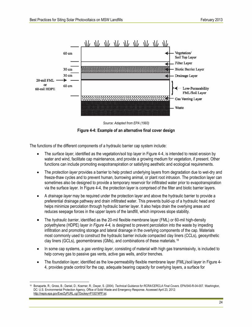
Best Practices for Siting Solar Photovoltaics on MSW Landfills February 2013
24
Source: Adapted from EPA (1993)
Figure 4-4: Example of an alternative final cover design The functions of the different components of a hydraulic barrier cap system include:
• The surface layer, identified as the vegetation/soil top layer in Figure 4-4, is intended to resist erosion by water and wind, facilitate cap maintenance, and provide a growing medium for vegetation, if present. Other functions can include promoting evapotranspiration or satisfying aesthetic and ecological requirements.
• The protection layer provides a barrier to help protect underlying layers from degradation due to wet-dry and freeze-thaw cycles and to prevent human, burrowing animal, or plant root intrusion. The protection layer can sometimes also be designed to provide a temporary reservoir for infiltrated water prior to evapotranspiration via the surface layer. In Figure 4-4, the protection layer is comprised of the filter and biotic barrier layers.
• A drainage layer may be required under the protection layer and above the hydraulic barrier to provide a preferential drainage pathway and drain infiltrated water. This prevents build-up of a hydraulic head and helps minimize percolation through hydraulic barrier layer. It also helps drain the overlying areas and reduces seepage forces in the upper layers of the landfill, which improves slope stability.
• The hydraulic barrier, identified as the 20-mil flexible membrane layer (FML) or 60-mil high-density polyethylene (HDPE) layer in Figure 4-4, is designed to prevent percolation into the waste by impeding infiltration and promoting storage and lateral drainage in the overlying components of the cap. Materials most commonly used to construct the hydraulic barrier include compacted clay liners (CCLs), geosynthetic clay liners (GCLs), geomembranes (GMs), and combinations of these materials.18
• In some cap systems, a gas venting layer, consisting of material with high gas transmissivity, is included to help convey gas to passive gas vents, active gas wells, and/or trenches.
• The foundation layer, identified as the low-permeability flexible membrane layer (FML)/soil layer in Figure 4-4, provides grade control for the cap, adequate bearing capacity for overlying layers, a surface for
18 Bonaparte, R.; Gross, B.; Daniel, D.; Koerner, R.; Dwyer, S. (2004). Technical Guidance for RCRA/CERCLA Final Covers. EPA/540-R-04-007. Washington,
DC: U.S. Environmental Protection Agency, Office of Solid Waste and Emergency Response. Accessed April 23, 2012: http://nepis.epa.gov/Exe/ZyPURL.cgi?Dockey=P10074PP.txt.

Best Practices for Siting Solar Photovoltaics on MSW Landfills February 2013
25
installation of geosynthetics, and, in some cases, a buffer to help control for the effects of differential settlement (EPA 2004).
4.2.2.2.2 Age and Thickness
The age and thickness of a landfill can be an indicator of settlement potential. The rates of both uniform and differential settlement are largely a function of the composition of the waste material and the age of the landfill cap.19 The rate of settlement will usually diminish over time, though settlement rates can increase at later stages due to shifts in biological or other processes over time. In general, landfills that have been capped in recent years will experience higher rates of settlement than landfills that were capped a decade or more ago. Records for the landfill may provide insight on settlement and landfill cap construction. For example, the post-closure plan generally provides detailed information on the landfill design, maintenance plan, as well as on-going requirements or restrictions. Where records may be incomplete regarding past landfill operations, age can be combined with other information (e.g., site visits and field investigations) to provide an indication of landfill construction and waste composition. Knowledge of the age and composition of the waste in the landfill may provide insights into the potential for settlement on the landfill surface. Both of these factors can impact the selection, design, and construction of PV technologies on landfill surfaces. 4.2.2.3 Slope and Stability
The collection and analysis of the slope and soil stability characteristics of a landfill property is a critical element of a feasibility assessment of landfill PV projects. These characteristics play a significant role in the selection of PV technology components and in the design and layout of the solar arrays decision. Topographic maps, site surveys, site engineering drawings, and soils engineering studies that may be included in the landfill post-closure plan typically contain the information necessary to complete a slope and stability assessment. Landfills that have minimal grades are often the best candidates for solar development as they simplify the design requirements of a PV system, minimize site preparation activities and costs, and may reduce the costs of PV system foundation and structural components. For this reason, the plateau or top of the landfill may present the best option for siting solar at some landfill sites. These areas generally have minimum grades of 2-3 percent to minimize the rainwater infiltration through the cap, reduce erosion, and avoid ponding. These gradual slopes are ideal for PV system installation, especially when constructed to face south, thereby increasing sunlight exposure. Many landfills are composed of large mounds of capped waste with steep slopes (3:1 slope or 30+ percent grade). Most solar developers place an upper limit of 5-10 percent grades in considering the feasibility of installing a PV system on a slope. As the grade increases, the complexity of the design increases as well, often resulting in a commensurate increase in system price. Installing PV arrays on steep slopes can lead to system design challenges associated with wind loading, erosion concerns, stormwater management issues, and foundation stability requirements. These challenges often lead to increased system costs for ballasted or anchored PV systems, or the selection of an alternative mounting system such as a PV-integrated geomembrane on the sloped portions of the landfill. While the sides of these landfills generally have steep slopes, the relatively flat top portion of the site may provide sufficient acreage for a PV system while not increasing costs associated with accommodating steep slopes. The orientation (or azimuth20) of the slope is equally important as the grade, since it can have a significant impact on the energy production of a PV system. The slope orientation determines the angles that the sun’s rays hit the PV modules. Developers generally prefer south facing slopes, or those within 20-30 degrees of due south to provide sufficient exposure to the sun over the course of the year. Slope orientations outside of the 20-30 degree range of due south will typically result in lower annual energy production from the PV system, and may necessitate additional design work and system layout modifications to address row-to-row shading issues. Sometimes developers seek to
19 El-Fadel, M.; Khoury, R. (2000). “Modeling Settlement in MSW Landfills: a Critical Review.” Critical Reviews in Environmental Science and Technology (30:3);
pp. 327-361. Print. 20 The azimuth angle is the compass bearing towards which the modules are pointed.

Best Practices for Siting Solar Photovoltaics on MSW Landfills February 2013
26
address slope orientations outside of the preferred range by bringing in additional fill material, or grading the existing slope to change its orientation. However, this approach may add cost to the project, and/or present challenges in complying with applicable landfill post-closure care requirements, including landfill cap integrity requirements. For these reasons, it may be preferable to only consider development on landfill areas that have slope orientations within the range of +/- 20-30 degrees of due south. The soil stability of sloping areas or side-slope stability is another relevant engineering consideration, and it is recommended to include a review of appropriate soils engineering studies and geotechnical data regarding the cap material during the feasibility assessment. Of particular importance is consideration of the caps’ ability to withstand both the construction and long-term operation of the PV system. The installation of solar arrays on steep side slopes can be particularly challenging, as the weight of the system places additional force on the cap compared to systems that are mounted on flat surfaces, and can result in failure of the side slope if the system is not properly designed. Building on side slopes typically results in a higher cost system, as the system is typically designed with stronger foundations while balancing the need to manage or control erosion, stormwater runoff, wind, snow, and/or seismic loading, and impacts to the PV system from differential settlement. Based on these considerations, the landfill plateau or buffer areas may offer the greatest potential for installation of a PV system. 4.2.2.4 Settlement
Another important element in assessing the feasibility of a landfill solar project is the collection and review of information on the potential for settlement of the landfill cap. All landfills are prone to settlement, but the type and magnitude of the settlement needs to be investigated during the decision-grade feasibility assessment phase of the project. There are two types of settlement that occur in landfills: uniform and differential. Uniform settlement refers to a process where the waste material in the landfill decays evenly and results in the level of the landfill cap settling at similar or uniform rates over large areas. Uniform settlement is typically not a significant concern in planning for a PV installation on a landfill. Differential settlement refers to the process where the waste material decays at different rates throughout the landfill, resulting in uneven settlement of the landfill cap. Differential settlement may result for a variety of reasons and is often a function of the waste material composition. For example, some areas of the landfill may have more organic waste that is prone to a higher rate of decay and settlement than other areas which may contain a higher volume of non-organic materials that have lower rates of decay or natural settlement. As a result, some areas of the landfill may settle at different rates resulting in an uneven cap surface. Differential settlement is a significant concern for landfill solar projects, as it may place uneven stresses on the mounting systems and cause uneven settlement of the array foundations, which may result in the misalignment of the array configurations and significantly decrease energy production. If the alignment of the PV arrays is impacted, then the modules will not be in their optimum orientation and reductions in system energy output may occur. Depending on the degree and location of settlement, differential settlement may also cause structural damage to the PV mounting system. The rates of both uniform and differential settlement are largely a function of the composition of the waste material and the age of the landfill cap. Landfills that have been capped in recent years may experience higher rates of settlement than landfills that were capped a decade or more ago. As the age of landfill cap increases, the rate of settlement is likely to diminish or become negligible. Landfill solar developers generally avoid projects on landfills that have been capped for less than two or three years due to the high rate of settlement expected during the early years after landfill closure. It is recommended to monitor settlement and evaluate actual settlement data, since some landfills may continue to experience high rates of settlement for more than five years. Many landfill operators have conducted forecasts that estimate the potential for uniform and differential settlement throughout the site. If a forecast has not been conducted, consideration should be given to conducting one. A settlement forecast can be useful to assess the potential magnitude of uniform and differential settlement, and may provide information on areas of the landfill to avoid placement of solar arrays in the context of a feasibility

Best Practices for Siting Solar Photovoltaics on MSW Landfills February 2013
27
assessment. A settlement forecast can also be leveraged in the design phase of the project in order to project effects of PV system weight on landfill cap settlement. 4.2.2.5 Erosion Control and Vegetative Cover
A vegetative cover strategy and erosion control management plan is usually included in a landfill post-closure plan. The vegetative cover on the landfill cap is usually a critical component of the erosion control management plan. The vegetative cover is designed to absorb some stormwater runoff and also allows for infiltration of runoff through the cover to an underlying soil layer where it is directed to holding ponds or other suitable containment locations. In addition, the vegetative cover is designed to hold the surface layer of the landfill cap together and minimize soil erosion due to stormwater runoff. As part of the decision-grade feasibility assessment, it will be important to obtain and review the erosion control management plan and vegetative cover specifications to help ensure that PV system options under consideration will be compatible with any post-closure plan provisions. Certain PV system options may also necessitate modifications to the erosion control management plan, vegetative cover strategies, and/or the post-closure plan. The costs and timing of these modifications may impact the feasibility of the project. If a landfill is developing erosion control plans and vegetative cover strategies as part of the closure and post-closure planning process, the owner or operator should consider integrating PV options into those plans. For ballasted or shallow poured concrete footer PV foundation systems, the design and specification of erosion control measures might incorporate the placement of PV foundations and support structures. Alternatively, the use of a PV-integrated geomembrane can be investigated as a replacement for conventional erosion control and vegetative cover systems and, if available, incorporated into the closure and post-closure plans. 4.2.2.6 Control of Leachate and Landfill Gas
Landfill leachate is the result of water filtering through the waste material that settles near the bottom of the landfill. The composition of landfill leachate is dependent on the type of waste contained in the landfill and may present risks to human health and the environment. Nearly all landfills use leachate collection and treatment systems. Typical leachate collection and conveyance systems comprise a network of piping in the waste material that allows drainage of the leachate to a sump area at the bottom of the landfill cell. The leachate is then pumped from the sump to an above ground on-site site storage and treatment facility. Landfill gas collection and production systems are somewhat similar to leachate collection systems, in that they typically consist of a network of pipes that are embedded throughout the waste material in the landfill cell to collect and transport landfill gas generated by decaying waste. The collected landfill gas is typically transported through pipes to a collection area where it is either flared or scrubbed and used for on-site electricity generation. Several key factors to consider in assessing the feasibility of PV systems on landfills with respect to leachate and landfill gas systems include weight loading and PV positioning relative to these systems. The weight bearing capacity of the piping and collection systems should be considered during the feasibility study. While there is already an enormous amount of weight resting on top of the leachate and gas collection systems, consideration should be given to the impacts on these systems of additional weight loading resulting from the PV system, as well as the weight of trucks and equipment that will be utilized in the site preparation and construction phases of PV installation. The feasibility assessment should also consider the location of leachate and gas piping systems, leachate and gas storage facilities, gas monitoring wells, and gas flaring and generation facilities. The location of these facilities may impact the design layout of the PV system, to the extent that the PV system may affect the operation and maintenance of piping, collection, or monitoring systems. In addition, locating PV arrays a safe distance away from landfill gas collection, monitoring, storage, flaring, and other energy generation systems is an important consideration. Landfill gas is explosive, and if a PV system is sited too close to landfill gas operations the potential of sparking from the PV system could present an explosive hazard. For these reasons, it is important that enclosed structures and subsurface conduits used for the management of landfill gas be designed to prevent concentration or conveyance of explosive gas. Therefore, a review of leachate and landfill gas systems should be conducted as part

Best Practices for Siting Solar Photovoltaics on MSW Landfills February 2013
28
of the decision-grade feasibility assessment to evaluate weight loading on these systems from the PV arrays and construction equipment, as well as to assess the impacts of these systems on the design layout of the PV arrays. 4.2.2.7 Stormwater Management
Stormwater management considerations are closely tied to erosion control and vegetative cover systems. Landfill covers are typically designed to absorb some stormwater runoff in the vegetative cover layer of the cap, while providing for additional run off to infiltrate into an underlying soil layer where it can be conveyed to retention ponds or other discharge areas. Landfill caps are also typically designed to allow for surface conveyance of stormwater that is not absorbed into the sub-surface conveyance system via uniform sheeting. This function is typically accomplished by incorporating a slight slope into the cap to direct water into stormwater collection areas and to prevent channeling of stormwater runoff, which can lead to erosion and fissures in the landfill cap. Stormwater discharges from active and closed landfills are subject to National Pollutant Discharge Elimination System (NPDES) permitting under the Clean Water Act (CWA) as stormwater discharges associated with industrial activity (see 40 CFR 122.26(b)(14)(v)). These discharges are typically covered by general permits, e.g., EPA’s multi-sector general permit (MSGP).21 In general, landfill operators are required to develop and implement a stormwater pollution prevention plan (SWPPP), which describes best management practices (BMPs) and controls to minimize discharge of pollutants in stormwater runoff from these facilities. To assess the feasibility of a PV system on a landfill surface, it will be important to understand these and other applicable storm water management requirements. It will also be important to understand how the PV system components could interact with the existing stormwater management system, and to limit feasible design alternatives to those that comply with regulatory requirements. In addition, the CWA requires separate permits for stormwater discharges from active construction. Information should be collected on stormwater permitting requirements during the construction process, as well as operations and maintenance requirements of the stormwater management system resulting from the placement of PV modules on the landfill cap. The cost and schedule of stormwater permitting should also be assessed as part of the overall decision-grade feasibility assessment. The landfill operating status may affect considerations associated with stormwater management during the feasibility analysis. If a landfill is not closed, a re-design of the stormwater management system in the existing closure and post-closure plans may be possible in order to ensure compatibility between the PV and storm water management systems. The construction of a co-designed stormwater management and conventional foundation-based PV system may save time and money in the long-run, even if the PV system is not built until several years later while waiting for the initial settlement of the landfill to occur. Alternatively, a PV-integrated geomembrane can be investigated as the primary stormwater management system on areas of the landfill cap, and if available, can be incorporated into the landfill closure plan. In addition, on-site recovery and reuse of stormwater may be considered in order to clean PV modules if appropriate, especially in regions with limited precipitation or water resources. In this case, a water treatment system could be used to remove minerals from the stormwater, thereby avoiding leaving residue on the PV modules. Refer to Section 7.2 Panel Washing and Water Management Plan or Natural Cleansing for additional information.
4.2.3 Institutional controls
Institutional controls (ICs) may be established for the landfill and should be taken into account as part of a feasibility analysis. In general, institutional controls are non-engineered instruments, such as administrative and legal controls, that help minimize the potential for human exposure to contamination and/or protect the integrity of a landfill.
21 Specific applicable requirements may vary depending on whether EPA or the state is the NPDES permitting authority. The MSGP is available in states and
Indian country where EPA is the permitting authority. All but five states have been authorized by EPA to administer the NPDES program, and most states issued general permits similar to the MSGP for industrial stormwater discharges. For more information on the MSGP, see http://cfpub.epa.gov/npdes/stormwater/indust.cfm. Landfills are classified in Sector L of the MSGP, and more information on requirements for this sector may be found at http://www.epa.gov/npdes/pubs/sector_l_landfills.pdf.

Best Practices for Siting Solar Photovoltaics on MSW Landfills February 2013
29
ICs are typically designed to work by limited land and/or resource use (e.g., uses of ground water) or by providing information that helps modify or guide human behavior at a site. ICs may also specify requirements for inspections and monitoring (e.g., to ensure that landfill wastes and contaminated media are not migrating from the site). Examples of institutional controls that may be applicable to contaminated sites include but are not limited to:
• Proprietary controls, such as easements or covenants, prohibiting activities that may compromise the effectiveness of the landfill in containing wastes;
• Governmental controls, such as zoning, building codes, ground water use regulations, and sports/recreational limits imposed by federal, state and/or local resources and/or public health agencies;
• Enforcement and permit tools with IC components, such as landfill closure permits that limit certain activities and/or require activities, such as inspections and monitoring, to ensure effectiveness of engineering and/or institutional controls; and
• Informational devices, such as deed notices, that provide information or notification to local communities that residual or contained contamination remains on site.
It is recommended that the feasibility study identify institutional controls applicable to the landfill, their type, and evaluate any impact(s) on whether a PV system can be developed, and/or any implications for the layout of the PV system components and usable area of the landfill.
4.2.4 Long term maintenance requirements
Many landfills have specific maintenance requirements to ensure the integrity of the landfill cap and other systems. Maintenance requirements typically go hand-in-hand with inspection requirements and can include, but may not be limited to: 22,23
• Routine maintenance of vegetative cover and re-vegetation; • Inspection, routine maintenance, and repairs to the:
o Leachate collection and treatment systems; o Landfill gas collection and treatment systems; o Stormwater collection and treatment systems;
• Routine inspection and cap repairs; and • Inspection, routine maintenance, and repairs to gas, ground water, and other monitoring systems.
These maintenance activities generally require access for personnel and equipment to the landfill systems. Similarly, maintenance of vegetated covers may require mower access. Thus, these activities may affect the layout of the PV system and PV system structures.
4.3 PV Technology Selection and Technical Design The following sections review information on the selection of PV technology components for landfill applications, as well as the development of a preliminary or “conceptual” system design to assist in the decision-grade feasibility assessment. It also reviews additional feasibility considerations such as predicting the energy output of the system and assessing the economic characteristics of potential projects.
4.3.1 Matching Appropriate PV Technology to Landfill Characteristics
Once the landfill site characteristics have been reviewed and analyzed for their impacts on the feasibility of a PV system, the next step in a typical decision-grade feasibility assessment is to select appropriate PV technology 22 Solid Waste Disposal Facility Criteria: Technical Manual. (1993). EPA/530-R-93-017. Washington, DC: U.S. Environmental Protection Agency, Office of Solid
Waste and Emergency Response. Accessed April 23, 2012: http://www.epa.gov/waste/nonhaz/municipal/landfill/techman/index.htm. 23 Stormwater O&M Fact Sheet: Preventative Maintenance. (1999). EPA/832-F-99-004. Washington, DC: U.S. Environmental Protection Agency, Office of
Water. Accessed April 23, 2012: http://www.epa.gov/npdes/pubs/prevmain.pdf.

Best Practices for Siting Solar Photovoltaics on MSW Landfills February 2013
30
applications based on site characteristics and landfill system requirements. While the information is presented as sequential steps, it is likely that the process of selecting appropriate PV technologies will be an iterative process that examines trade-offs among technology components. Often, an initial step is the selection of the type of PV module to be used, which may be based upon obtaining the desired system size (kW) within the available land area. Modules are typically evaluated in combination with compatible mounting systems and foundations. Each integrated PV system (modules, mounting system, and foundations) is assessed with respect to compatibility with site conditions.
Source: PV Navigator
Figure 4-5: Sample solar PV and landfill integrated system design
When reviewing options for foundation supports, the choices are typically ballasted, shallow poured concrete footings, an auger/helical pier anchoring system, or a PV-integrated geomembrane. Each of these foundation types are described in more detail in Section 5.2 "Anchoring Systems". Next, options for the mounting system and array orientation are evaluated. Typically, fixed-tilt mounting systems are selected for landfill applications. Fixed-tilt systems are typically oriented due south and titled at an angle equal to or less than the latitude of site location. In some instances, it may be desirable to lower the tilt angle in order to maximize the output for summer production, to reduce row-to-row shading impacts, and/or to allow for more modules to be placed in a fixed amount of area. Single- and dual-axis trackers are largely avoided on landfill surface areas for several reasons. First, single-axis tracking systems are typically designed with driven pile or post and pier foundations, which are rarely used in landfill applications; while dual-axis trackers typically require large concrete foundations that are typically too heavy for use on landfills and also require penetration. However, tracking systems with ballasted foundations may be viable. Second, and perhaps more importantly, differential settlement of the landfill cap may result in the single- and dual-axis tracker arrays going out of alignment; even small alignment issues can have significant negative impacts on energy production. Differential settlement may also impact alignment along the tracking axis, which may cause damage to structural members or the actuators that rotate the arrays to track the sun and, in turn, impact energy

Best Practices for Siting Solar Photovoltaics on MSW Landfills February 2013
31
production. However, some developers have considered developing a combined or hybrid system of fixed-tilt arrays on the landfill surface with single-axis tracking systems on the buffer areas around the landfill. In addition, for landfills that have not completed the closure process, it may be desirable to select a PV-integrated geomembrane. Since the geomembrane can be substituted as the final cap cover for a similar price to a conventional cover, it may be a cost-competitive PV solution. Several geomembrane PV technologies are available in the market, ranging from thin film PV laminates that are flush mounted with the landfill surface, to geomembranes incorporating mounting frames that allow for modules to be mounted at fixed tilt angles of up to 20 degrees. New membrane materials have been recently introduced to the market with 30- and 35-year limited warranties, which matches or exceeds the typical warranty periods for PV systems.
4.3.2 Conceptual Design of Major System Components
Development of a conceptual design of the PV system is usually one of the final steps in a feasibility assessment. Conceptual designs are typically thought of as an initial estimate of the PV system’s components and characteristics, but do not usually go into the level of detail of an engineering design. A conceptual design generally includes the selection and sizing of the potential components of the PV system, a preliminary layout or calculation of the footprint size of the system, and cost estimates for the system. The following system components and high-level specifications typically in a conceptual design include:
• Foundation type: typically ballasted, shallow poured concrete footings or helical pier
• Mounting system: fixed tilt, single- or dual-axis tracking or geomembrane
• PV module type: mono- or poly-crystalline or thin film
• PV module efficiency
• Inverter type and efficiency Determining the size of the PV system is a function of whether the system is designed to meet on-site energy needs for a net-metering application, or whether it is intended to be an exporter of power to the grid. In the case of the PV system being designed to meet on-site loads, the system can be sized to meet up to 100-120 percent of the annual energy requirements of the facility based on the PV system’s projected output on a kilowatt-hour/kW basis, depending on local net-metering laws. However, if the objective is to size the PV system to be as large as possible based upon the available space, then an initial system layout (i.e., preliminary design footprint) may be created to determine the potential energy production for a given site. At a minimum, some preliminary calculations would be necessary to determine the spacing distance between rows of arrays based on module size and system support structure height, and then to determine how many rows (or partial rows) can fit in the available landfill space, excluding areas previously identified in the site characterization phase that are not suitable for PV. Such calculations will result in an approximate value for the resulting system size based on the objective of maximizing its size based on the available land areas suitable for PV development. The third major component of a typical conceptual design is an estimate of the installed cost of the system. There are several ways to obtain cost estimates. The system costs can be estimated based on a comparison to similar projects completed in the region (usually on a $/Watt basis), or an installer/developer can be contacted and requested to provide indicative pricing, or component manufacturers/distributors and local contractors can be called for price estimates for each component of the system. However, this last method can be time consuming and may be no more accurate than doing a comparative analysis to other recently completed systems in the area in terms of size, type, and application. Once complete, the conceptual design is generally used to determine the technical and economic feasibility of the project in terms of its expected system output (annual MWh), and economic value metrics such as its levelized cost of energy, payback period, net present value, and internal rate of return, all of which are discussed in the sections that follow.

Best Practices for Siting Solar Photovoltaics on MSW Landfills February 2013
32
4.3.3 Energy Prediction
Based on the siting considerations outlined above, the useable acreage for the PV system can be estimated using aerial maps, drawings, or actual measurements from a site visit. Table 4-2 outlines the energy density values that can be expected from each type of system and can be used to estimate total system capacity for a ground mounted system.24
Table 4-2: Energy Density by Module and System Type for Ground-mounted PV
Module Type
System Type
Fixed-tilt
Single-axis Tracking
Crystalline Silicon 2.9 - 5.5 DC-Watts/ft2
(31.2 - 59.2 DC Watt/m2) 2.4 - 4.5 DC-Watts/ft2
(25.8 - 48.4 DC Watt/m2)
Thin Film 1.7- 2.9 DC-Watts/ft2
(18.3 - 31.2 DC Watt/m2) 1.4 - 2.4 DC-Watts/ft2
(15.1 – 25.8 DC Watt/m2)
Estimated system capacity can be used as one of the inputs for tools to estimate energy production, such as Solar Advisor Model (SAM) and PVWatts. Please refer to Appendix B for additional information on these tools.
4.3.4 Economic Considerations
PV systems will produce energy anywhere there is sun and will produce more where there is a lot of sun. However, economic viability depends not only on the solar resource but also on economic factors pertaining to the site. Economic incentives for PV, such as state renewable electricity requirements with specific solar targets, increase the value of solar-produced electricity. The Database of State Incentives for Renewable Energy (DSIRE) is a comprehensive source of information on state, local, utility and federal incentives and policies that promote renewable energy and energy efficiency.25 Because landfill sites generally have smaller loads (e.g., a couple of lighting systems or small appliances) when compared to the total PV production, most systems will likely sell electricity through a Power Purchase Agreement (PPA) with the local utility, making collaboration with the utility vital. For sites with larger loads, a “net metering” option through the local utility may be sufficient to drive project economics by offsetting the retail rate of electricity with the production from the PV system. Other key economic factors that can improve a PV system’s viability are high electricity rates or time-of-use (TOU) electricity rates that are high during the sunny parts of the day, solar feed-in tariffs, and other solar incentives associated with Renewable Portfolio Standards (RPS) or sales of Solar Renewable Energy Credits (SRECs). Additional discussion on financing and deal structures is provided in Appendix C. Most projects will need to select a financing mechanism, which can be a complex decision since solar projects tend to have long paybacks and necessitate long-term contracts, unless high energy or system repayment costs can be accommodated in the short run.
4.4 Other Potential Feasibility Factors The following sections present information on additional factors might be considered in assessing the feasibility of landfill PV system including potential visual impacts and mitigation strategies, utility interconnection requirements, and utility policies for net-metered systems.
24 Energy densities are intended to be used for assessing initial potential PV capacity during a feasibility study phase. Actual design may vary. Data based on
information from large-scale PV systems using a range of different module technologies and efficiencies. This table does not provide energy density information for solar geomembranes.
25 Database of State Incentives for Renewable Energy: www.dsireusa.org

Best Practices for Siting Solar Photovoltaics on MSW Landfills February 2013
33
Highlight 4-2: Examples of Community Engagement Seek input from community stakeholders early and often during project planning and implementation to understand their interests and concerns. It is especially important to provide information about the project in ways that all parts of the community can understand. Consider engaging the community by:
• Creating a project-specific website with project information, architectural renderings, and project contacts
• Hosting on-site demonstrations to allow the public to view a life-size system
• Holding a solar education day at a local school
4.4.1 Community Engagement & Support
Communities may have a strong interest in the long-term reuse of the MSW landfill. Many community groups may not only want to take part in discussions about solar energy on MSW landfills, but in some cases may want to learn more about solar technology in general, to provide additional support as community advocates for the project, and to provide local insight into specific community needs or considerations that may be relevant to the solar development. With this in mind, the RE-Powering initiative promotes reuse of MSW landfills for renewable energy projects when they address community concerns, interests, and land use plans. The EPA promotes active community engagement in all land revitalization efforts, including reuse of landfills through solar energy projects. The EPA’s vision is that the end use of a site should be determined through a combination of the community’s vision, key site characteristics, and community assets and should be protective of human health and the environment. MSW landfills are subject to varying federal, state, and/or local level regulatory requirements and authorities as is noted in Chapter 1 and 2 of this document. Although the requirements for public notice and involvement may vary, this section focuses on general considerations for community engagement that may be important in siting PV on closed landfills. 4.4.1.1 Benefits of Community Engagement
Involvement of surrounding communities is important to the success and timeliness of projects, including large scale renewable energy projects such as siting solar PV on MSW landfills. When it is appropriate, community input about site reuse should be obtained early in a project. Continued engagement can help not only to inform the community about project plans, but also to gather information about the general setting for the project and ways it can be designed to be consistent with the community vision and benefit the community. Key community stakeholders can share insight into the community’s vision as well as potential concerns or issues that community members may have regarding reuse of the landfill. For example, there may be active community groups working to reuse the closed landfill as a park and recreation area, which may not be compatible with a PV installation at the site. 4.4.1.2 Openness and Transparency
Open dialogue with the community, actively listening and responding to community concerns or requests, and transparent decision-making processes can help to foster proactive relationships between stakeholders and developers. These actions can also help to build trust and credibility. Failure to be transparent and open with communities could result in delays or other impacts to project progress. 4.4.1.3 Facilitating Community Engagement
There are multiple ways that a developer can facilitate community engagement on renewable energy projects. During the “decision-grade” feasibility assessment (outlined in Chapter 4), developers typically discuss future land use options with local planning authorities, local officials, and community members. Directly involving the community through informational and town hall sessions can provide valuable community insight and a provide forum for addressing community concerns. In some cases community groups may be interested in partnering with the developer on projects.26 Communities may be interested in a wide range of topics, which may vary by site and situation. Community or stakeholder questions and concerns may include:
26 “Hartford Solar Landfill Project.” Center for Public Environmental Oversight, Accessed January 18, 2013: http://www.cpeo.org/pubs/HartfordSolar.pdf

Best Practices for Siting Solar Photovoltaics on MSW Landfills February 2013
34
• What are the benefits or costs of solar energy to the community?
• How does a solar energy system work?
• How does a solar energy system differ from a coal- or natural gas-fired power plant?
• How will solar reuse affect site access?
• What will be the duration of site construction?
• How will the solar system be installed to maintain landfill cap integrity?
• What are the greater environmental impacts of solar reuse on the landfill?
• How reuse will impact future landfill upkeep and maintenance?
• What are the visual, aesthetic and economic impacts to the site and neighboring communities?27
• What are the job opportunities during construction and operation of the solar energy system? For effective community engagement, the credibility and rapport of the developer’s representative can be a critical element to the success of the project. Collaborative partnerships between communities, various stakeholders, and developers can facilitate successful reuse and development projects by taking into account community interests and supporting community participation in the decision making process.
4.4.2 Visual Impacts and Mitigation Strategies
Solar PV projects may, at times, raise concerns or face opposition due to perceived or real visual impacts of the arrays and support structures. During the permitting and public comment process, concerns may be raised as to the type of fencing around the perimeter of facility, or the aesthetic impacts of the solar facility on the surrounding community. In nearly all cases, issues and concerns related to visual impacts of a solar facility can be addressed easily and cost-effectively. In some instances, mitigation strategies can be as simple as not using barbed- or razor wire on the tops of fencing in areas that are visible to the public, or ensuring that security lighting is motion-activated so that the lights are not on all night, thereby disturbing nearby residents. Other mitigation strategies that may be deployed in response to visibility concerns include building earthen berms or planting trees around the perimeter in such a manner that the view of the solar arrays is blocked from view, but the berms or trees do not obstruct the sun’s rays from hitting the PV panels.
4.4.3 Interconnection
All grid-connected PV systems require an interconnection agreement, and there are no specific conditions for landfill-based systems. An interconnection agreement specifies the terms, conditions, and equipment requirements for a grid-interactive PV system. Interconnection agreements are typically handled through the local distribution utility serving the site. Depending on the size of the PV system and the utility processing the interconnection agreement, the interconnection process can be time consuming and incur costs. For smaller, net-metered systems, the process can be as simple as a one-page contract. For larger PV systems that are exporting power to the grid, the process is likely to be more detailed and costly. For larger PV systems in general, the system owner will be required to submit an interconnection application typically to the local utility, which typically includes a nominal fee for the utility to conduct an initial study on the impacts of the PV system on the local distribution systems. If the proposed PV system passes the utility’s initial screening process, then typically a more detailed power flow analysis study will be conducted by the utility for an additional cost to the applicant. This study will typically include an analysis of the impact of the PV system on the utility grid and whether local line upgrades or additional interconnection equipment is required for interconnection.
27 “Amherst, Massachusetts: Impediments to Solar Installations on Closed Landfills.” Center for Public Environmental Oversight. Accessed January 18, 2013: http://www.cpeo.org/pubs/AmherstSolar.pdf

Best Practices for Siting Solar Photovoltaics on MSW Landfills February 2013
35
Increasingly, utilities are requiring system upgrades as part of the interconnection contract approval, and the upgrade costs are borne by the applicant. The entire interconnection review and approval process can take from 6-12 months depending on utility review and analysis periods, and the number of interconnection requests they are processing. During the decision-grade feasibility assessment phase of the project, it will be useful to contact the local distribution utility and obtain information on the interconnection application requirements, costs, and anticipated schedule.
4.4.4 Net Metering
Net metering is a utility policy incentive that encourages development of PV and other renewable energy systems by its customers to offset on-site energy requirements. There are several variations among utility net metering policies, but the most common approach allows customers to receive full credit for every kilowatt-hour generated by the on-site renewable energy system. With respect to PV, when the system is generating energy, it offsets the customer consumption behind the meter. If the PV system is generating more energy than the on-site load, then the excess energy is exported to the utility grid and spins the meter backwards, in essence generating a credit or banking the excess energy with the utility. Then, as the energy generated by the PV system drops below the on-site energy requirements, the credits banked with the utility are drawn back. Thus, customers receive a one-to-one credit for PV generated on-site whether or not it was consumed by on-site loads at the time of generation. When monthly PV energy generation exceeds the on-site monthly energy consumption, the credits for the kilowatt-hours generated are carried forward to the next month. Typically, at the end of the year there is a “true-up” period where the annual energy consumption and PV energy generation are compared. If there is excess generation at the end of the year, then depending on the utility, the customer may:
• Receive compensation for the excess generation at the utility’s avoided cost of energy (i.e., at a rate significantly lower than the customer’s retail rate);
• Lose the excess generation credit and receive no compensation from the utility; or
• Carry the excess generation credit forward into the next year’s billing cycle. If a net-metered PV project is being considered for a landfill site, it will be important to contact the local distribution utility and obtain a copy of its net-metering policy. Net metering policies vary widely, with some being extremely PV-friendly, while others are not. Net metering is limited to off-setting the energy requirements of on-site loads. In landfill settings, on-site loads typically tend to be small, consisting largely of leachate sump pumps, landfill gas well pumps and monitoring systems, and ground water monitoring systems. As a result, unless the landfill is part of a larger facility served by a utility master meter, net-metered PV systems on landfills will tend to be moderate in size.
4.4.5 Virtual Net Metering
Some states and utilities allow for virtual net metering (VNM) or remote net metering. This arrangement can allow certain entities, such as a local government, to install renewable generation within its geographic boundary and to generate credits that can be used to offset charges at one or more other locations within the same geographic boundary. Virtual net-metered systems are typically subject to a system-capacity cap, which varies at the state or utility level. As there is typically a mismatch between on-site electrical demands and the potential for PV system size based on usable acreage, virtual net metering may be an important vehicle for many PV systems installed at landfills. In this scenario, the energy produced at the landfill offsets energy consumed by “subscribers” offsite. This arrangement may improve the economic feasibility of the PV project. Refer to Appendix C the discussion of Community Solar Gardens for an example of virtual net metering.

Best Practices for Siting Solar Photovoltaics on MSW Landfills February 2013
36
Highlight 5-1: Major Considerations Impacting Solar PV Project Design on Landfills
• Landfill Cap Characteristics • Site Slope, Stability and Orientation • Waste Composition and Differential Settlement • Selection of Anchoring System • Selection of Mounting System • Selection of Modules • PV System Weight Considerations • Stormwater Management • Wind and Snow Loading Criteria • Cover Material Management • Site Security • Integration with Landfill Gas Monitoring and
Production Systems • Institutional Controls
5. Design Considerations Unique to Building PV Projects on Landfills Specific elements of the solar project are designed to meet the specific performance objectives identified for the project, including the performance objectives of the PV system and the landfill. Information gathered during the feasibility analysis can be used as a starting point for the solar project design. The following chapter outlines the key landfill characteristics to consider when designing a solar project on a landfill, including cap characteristics, waste composition and settlement forecasts, PV system layout and component system designs, and considerations regarding the integrated PV-landfill system. A summary of the design considerations unique to building PV projects on landfills discussed in Chapter 5 is provided in Chapter 8, Table 8-1. Note that this is not an exhaustive list of design considerations. Project stakeholders should consider whether different or additional approaches are appropriate in light of site specific conditions.
5.1 Landfill Characteristics Landfill characteristics will influence PV system design choices. Where there is little room to modify specific landfill components without compromising their function, these components will represent a design constraint. Where landfill components can be modified, the PV system designer will have greater flexibility. In all situations, the designer should consider not only the landfill characteristics as they exist prior to construction of the PV system but also how the PV system may alter those characteristics. Ultimately, the design should seek to optimize the performance of an integrated PV-landfill system.
5.1.1 Cap Characteristics
Characteristics of the landfill cap that will likely influence PV system design choices include:
• Landfill slope and slope orientation
• Thickness of cap, depth to specific cap components, and cap component function
• Post-closure, monitoring, maintenance, and use requirements These characteristics will affect the selection and design of foundation types, mounting systems, PV module types, and effective area for the PV system installation. The design of the PV systems should consider how to account for these factors in a way that maximizes the output that can be achieved by the PV system while not compromising the safe, effective, and compliant operation of the landfill. Table 5-1 provides several key characteristics of the landfill cap and their implications for the PV system design. The inter-relationships among cap characteristics and PV system design considerations and choices are discussed in Chapters 5.2 through 5.13.
Table 5-1: Inter-relationships Between Landfill Cap Characteristics and PV System Design
Cap Characteristics Design considerations
Slope • Steeper slopes generally require lighter-weight solar arrays and/or heavier foundations to anchor the system.
• Materials and methods used to construct steeper slopes can limit the design of PV systems, which can increase static and dynamic loading and affect side slope stability.

Best Practices for Siting Solar Photovoltaics on MSW Landfills February 2013
37
Table 5-1: Inter-relationships Between Landfill Cap Characteristics and PV System Design
Cap Characteristics Design considerations
Orientation • Slope orientations outside of +/- 20º-30º from due south typically result in lower annual energy production from the PV system. These slopes are generally either modified through grading to adjust orientation or not included in the useable acreage for the PV system.
Cap depth • The depth of the cap may limit compatible foundation types and design and, thus drive selection of PV mounting systems and PV module technologies. For example, foundation designs may be limited to ballasted foundation types, which may not be compatible with many single- or dual-axis tracking systems.
Cap components • Any cap modifications should ensure that there is no increase in potential threat to human health and the environment, and, if applicable, must comply with the closure and post-closure care requirements in 40 CFR 258 Subpart F. Additional federal, state, local and/or tribal requirements may apply.
• Foundation types and designs may be limited due to regulatory requirements for the final cover system. Refer to 40 CFR 258 Subpart F and other applicable federal, state, local and/or tribal requirements for additional information.
• PV system wiring may need to run through above-ground conduits and not in underground trenches to preserve cap function.
• Where shading could affect the presence and function (e.g., evapotranspiration, erosion control) of vegetative cover, cap may necessitate compensating design considerations.
• Structures and capacity of stormwater collection systems (e.g., location of swales, size of detention basins) may limit the layout of PV systems, limit the amount of impermeable area, or necessitate compensating design considerations.
• Depth and materials used for cap components designed for high transmissivity (e.g., drainage layer, gas venting layer) may limit the bearing capacity to prevent compression and loss of function.
• Location and depth of waste collection piping (e.g., gas, leachate) can affect the layout of the PV system.
5.1.2 Waste Composition
The following sections examine the importance of examining the composition of waste material in the landfill as part of the PV system design process. The composition of landfill waste may have a significant impact on the PV system design process as a result of potential differential settlement as well as the location and function of landfill gas and leachate collection systems located within the waste material. 5.1.2.1 Differential Settlement
Differential settlement occurs when waste material decays at different rates throughout the landfill, resulting in uneven settlement of the landfill cap. Differential settlement can be the result of many factors (e.g., operational practices, moisture composition), and is often the result of spatial variation and/or inhomogeneity in waste composition. Settlement results from mechanical, physiochemical, and biological processes, and the effects of these processes in terms of total settlement and rate of settlement, differs for different types of wastes. Settlement rates usually decrease with time, though they may increase as a landfill undergoes changes in active biological processes.
5.1.2.1.1 Differential Settlement Forecasts
Many landfill operators have conducted forecasts that estimate the potential for uniform and differential settlement throughout the site. If a forecast has been completed for a landfill property being considered for solar development, a copy of the forecast should be obtained and assessed for the potential magnitude of uniform and differential

Best Practices for Siting Solar Photovoltaics on MSW Landfills February 2013
38
settlement. If a forecast has not been conducted, consideration should be given to conducting one. El Fadel and Khoury28 and EPA29 have published information on methods used for settlement monitoring and forecasting. Pre- existing settlement forecasts should also be reviewed to assess the potential that the PV system will affect the forecast. Where a forecast is being conducted as part of the PV system design, it should consider the effect of the integrated PV-landfill system on uniform and differential settlement. In general, differential settlement will be of greater concern for the design of PV systems on landfills containing more inhomogeneous waste.30 This is a critical consideration in the design of landfill solar projects, as differential settlement can place uneven stresses on support structures and cause them to fail, and it can create uneven settling of support structures, with the potential to impact array alignment, long-term structural integrity of the PV system, and energy output. Differential settlement is a particularly important consideration in the design of single- and dual-axis tracker arrays, but even small alignment issues associated with other designs can negatively impact energy production.
5.1.2.1.2 Differential Settlement – System Design Considerations
As discussed throughout this document, differential settlement on landfills is a major consideration in the design of a PV system. There are three design factors that should be considered when addressing differential settlement:
• PV system component selection
• Siting of the PV system
• Engineering measures to mitigate settlement The selection of components for conventional ground-mounted PV systems may have a significant impact on the occurrence of differential settlement or correcting for differential settlement. PV technology components that result in higher dead weight loads may increase the probability of the differential settlement. Extremely heavy dead weight loads, such as those found in concrete slab foundations, can cause or exacerbate immediate differential settlement during the construction of the project, and can increase differential settlement concerns over the long-term. Even if the dead weight load of the PV system is within the acceptable design range based on the cover material weight bearing criteria, local variations in cap depth or waste material composition may make some areas of the landfill more susceptible to differential settlement. Therefore, minimizing the weight characteristics of a PV system is one potential design strategy for addressing differential settlement concerns. Another factor in the selection of PV system components is to consider mounting systems that can respond to differential settlement occurrences. With fixed tilt PV systems, minor incidents of differential settlement typically do not have sizeable impacts on PV energy production. However, if more substantial differential settlement occurs, it may impact the alignment of the array and reduce energy production. To correct for differential settlement after it occurs, it may be desirable to specify mounting systems that allow the use of shims or spacers to raise the array height to its pre-existing levels. Alternatively, mounting systems can be considered that have adjustable racking systems that allow for raising or lowering of the array height to correct for the localized differential settlement. PV-integrated geomembranes have fewer design considerations related to differential settlement than conventional ground-mounted systems. Since they are lightweight, they do not have dead weight loading concerns with respect to differential settlement. Minor occurrences of differential settlement may not be a large concern for geomembranes since the PV laminate is flush mounted with the cover surface of the landfill, and its energy production would not 28 El-Fadel, M.; Khoury, R. (2000). “Modeling Settlement in MSW Landfills: a Critical Review.” Critical Reviews in Environmental Science and Technology (30:3);
pp. 327-361. Print. 29 Bonaparte, R.; Gross, B.; Daniel, D.; Koerner, R.; Dwyer, S. (2004). Technical Guidance for RCRA/CERCLA Final Covers. EPA/540-R-04-007. Washington,
DC: U.S. Environmental Protection Agency, Office of Solid Waste and Emergency Response. Accessed April 23, 2012: http://nepis.epa.gov/Exe/ZyPURL.cgi?Dockey=P10074PP.txt.
30 Sharma, H.D.; De Ariban, M. (2007). “Municipal Solid Waste Landfill Settlement: Postclosure Perspectives.” Journal of Geotechnical and Geoenvironmental Engineering (133:6); pp. 619-629. Print.

Best Practices for Siting Solar Photovoltaics on MSW Landfills February 2013
39
generally be impacted by minor settlement. In the event of more extensive differential settlement that impacts PV energy production and/or stormwater runoff patterns, the geomembrane cover material has the ability to be cut, tightened, loosened, or repositioned as necessary and reattached to the adjacent cover material. The strategic placement of the PV system on specific areas of the landfill is another design strategy to mitigate the impacts of differential settlement. First, consideration should be given to siting the PV system on the oldest capped areas of the landfill first. The areas of the landfill that have been capped for the longest period of time have likely settled the most and will likely have the lowest rates of settlement in the future. On this basis, PV arrays could be sited on the oldest capped area first, followed by the next oldest area and so on. Second, differential settlement forecasts should be reviewed and revised to account for the additional weight of the PV system to determine areas more prone to differential settlement based on waste characteristics. For example, if the composition of waste materials is known throughout the site, the placement of the PV arrays over areas of waste known to have lower concentrations of organic waste material that is subject to natural decay from biochemical degradation may serve to lessen the effects of settlement on the PV system. Thus, an area containing construction, demolition, and/or industrial wastes may be preferable from a settlement standpoint to other areas known to contain household wastes. Engineering solutions on the landfill cap to reduce the probability and/or impacts of settlement may be considered as another possible strategy for addressing differential settlement. These include the use of soil tamping equipment to compact the soil in the landfill cover. Compaction of the soil increases its density and stability. Note that compaction activities, like other strategies, must comply with landfill post-closure management requirements and adhere to engineering specifications to avoid damage to the function of cap components below the surface. Compaction may be more suitable for landfills in the closure process, as soil compaction activities are often performed as part of the final cap installation. Additionally, the use of geo-grid reinforcement systems, while adding additional cost to a potential project, may be able to be incorporated into the landfill cover to provide increased soil stability and tensile strength, and protect against cracking and fissures caused by differential settlement. 5.1.2.2 Landfill Gas and Leachate
Waste composition also influences landfill gas and leachate control requirements. The PV system design may need to consider the gas and leachate typically found with the types of waste in the landfill. Mitigation or avoidance of gas or leachate releases is a consideration that may drive the selection of the PV mounting system and overall layout of the PV system. For example, foundation selection may be constrained in order to avoid creating preferential migration pathways, and changing the water balance in the landfill.
5.2 Anchoring Systems Selecting the appropriate anchoring system for the PV array is one of the most critical steps in the design phase, as the anchoring system is the building of the PV system and is the interface between the PV system and the landfill cap. Building upon the information collected and initial decisions made in the decision-grade feasibility assessment, the selection and final design of the anchoring system involves balancing a number of design factors specific to landfills, including system weight requirements, differential settlement, and wind and snow loading. Five types of anchoring systems are commonly used to support PV systems in landfill applications:
• Shallow poured concrete footers/ pre-fabricated concrete footings;
• Concrete slabs;
• Auger / helical pier supports;
• Ballasted systems; and
• PV-integrated geomembranes. As mentioned in Section 3.2.3.1, while driven pile foundations are widely used in conventional PV projects, they are not typically suitable for landfill applications. Since landfill caps are not always uniform in depth, there is a risk with
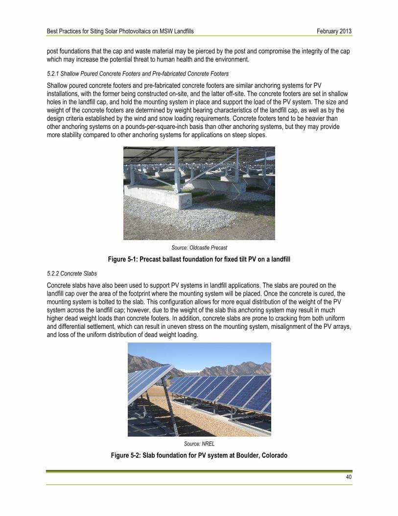
Best Practices for Siting Solar Photovoltaics on MSW Landfills February 2013
40
post foundations that the cap and waste material may be pierced by the post and compromise the integrity of the cap which may increase the potential threat to human health and the environment.
5.2.1 Shallow Poured Concrete Footers and Pre-fabricated Concrete Footers
Shallow poured concrete footers and pre-fabricated concrete footers are similar anchoring systems for PV installations, with the former being constructed on-site, and the latter off-site. The concrete footers are set in shallow holes in the landfill cap, and hold the mounting system in place and support the load of the PV system. The size and weight of the concrete footers are determined by weight bearing characteristics of the landfill cap, as well as by the design criteria established by the wind and snow loading requirements. Concrete footers tend to be heavier than other anchoring systems on a pounds-per-square-inch basis than other anchoring systems, but they may provide more stability compared to other anchoring systems for applications on steep slopes.
Source: Oldcastle Precast
Figure 5-1: Precast ballast foundation for fixed tilt PV on a landfill
5.2.2 Concrete Slabs
Concrete slabs have also been used to support PV systems in landfill applications. The slabs are poured on the landfill cap over the area of the footprint where the mounting system will be placed. Once the concrete is cured, the mounting system is bolted to the slab. This configuration allows for more equal distribution of the weight of the PV system across the landfill cap; however, due to the weight of the slab this anchoring system may result in much higher dead weight loads than concrete footers. In addition, concrete slabs are prone to cracking from both uniform and differential settlement, which can result in uneven stress on the mounting system, misalignment of the PV arrays, and loss of the uniform distribution of dead weight loading.
Source: NREL
Figure 5-2: Slab foundation for PV system at Boulder, Colorado

Best Practices for Siting Solar Photovoltaics on MSW Landfills February 2013
41
5.2.3 Augers or Helical Piles
Augers or helical piles are a type of post support with an auger configuration at the base of the pier. Unlike driven piles, they are screwed into the ground typically with the use of a hydraulic torque motor. The advantages of a helical pile anchoring system include quick installation, high stability and structural support, and low cost. The potential disadvantage is that like a driven pile foundation, it penetrates the landfill cap and presents risk of piercing the cap and entering the waste layer if shallow landfill cap depths are encountered. However, once the pile is set, it is less likely to sink further over time. This anchoring solution is more applicable to landfills with deeper and known cap depths, as well as in side slope applications, where additional support and stability is necessary, and buffer zones. See Section 6.3 for additional discussion on penetrations of the landfill cap and associated regulatory requirements that may be applicable.
5.2.4 Ballasted Systems
Ballasted systems are the most common anchoring method for PV systems on landfills. A ballasted system is typically composed of a flat tray or large concrete block that is placed on the landfill cap, with the array support structure attached to the tray or concrete block. In tray-based systems, the ballast material—usually pre-cast concrete blocks—are then placed on top of the tray. The weight of the ballast material holds the PV system down and protects it from wind uplift and sliding. The advantages of a ballasted anchor system are that: the system (i) does not penetrate the landfill cap; (ii) requires minimal site prep or disturbance to the vegetative cover; (iii) can be installed quickly; and (iv) can provide good structural support for the PV array. The key factor in designing a ballasted system is the selection of the proper weight of the ballast material to balance the dead weight loading requirements of the landfill cap while protecting against wind uplift and horizontal sliding. As ballasted anchoring systems become more commonplace for PV systems, an increasing number of manufacturers are offering pre-packaged ballast and racking solutions that are designed for site-specific conditions. Ballasted systems may be good candidates for flat landfill surfaces, but become more difficult to install as the slope of the landfill surface increases.
Source: SunDurance Energy LLC
Figure 5-3: Ballasted anchoring system at Landfill 1A project at New Jersey Meadowlands
5.2.5 PV Integrated Geomembranes
PV integrated geomembranes are an emerging PV technology solution for landfill applications. A PV-integrated geomembrane is a landfill cover, typically comprising a thermoplastic polyolefin (TPO) material, which can be used in place of a vegetative or other final cover on the landfill. PV-integrated geomembranes are usually only considered prior to beginning the landfill closure process, as they may be largely redundant if placed on top of a final landfill
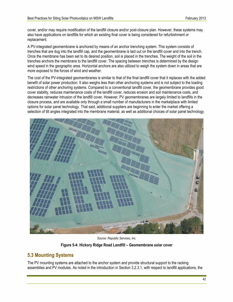
Best Practices for Siting Solar Photovoltaics on MSW Landfills February 2013
42
cover, and/or may require modification of the landfill closure and/or post-closure plan. However, these systems may also have applications on landfills for which an existing final cover is being considered for refurbishment or replacement. A PV-integrated geomembrane is anchored by means of an anchor trenching system. This system consists of trenches that are dug into the landfill cap, and the geomembrane is laid out on the landfill cover and into the trench. Once the membrane has been set to its desired position, soil is placed in the trenches. The weight of the soil in the trenches anchors the membrane to the landfill cover. The spacing between trenches is determined by the design wind speed in the geographic area. Horizontal anchors are also utilized to weigh the system down in areas that are more exposed to the forces of wind and weather. The cost of the PV-integrated geomembranes is similar to that of the final landfill cover that it replaces with the added benefit of solar power production. It also weighs less than other anchoring systems and is not subject to the loading restrictions of other anchoring systems. Compared to a conventional landfill cover, the geomembrane provides good cover stability, reduces maintenance costs of the landfill cover, reduces erosion and soil maintenance costs, and decreases rainwater intrusion of the landfill cover. However, PV geomembranes are largely limited to landfills in the closure process, and are available only through a small number of manufacturers in the marketplace with limited options for solar panel technology. That said, additional suppliers are beginning to enter the market offering a selection of tilt angles integrated into the membrane material, as well as additional choices of solar panel technology.
Source: Republic Services, Inc.
Figure 5-4: Hickory Ridge Road Landfill – Geomembrane solar cover
5.3 Mounting Systems The PV mounting systems are attached to the anchor system and provide structural support to the racking assemblies and PV modules. As noted in the introduction in Section 3.2.3.1, with respect to landfill applications, the

Best Practices for Siting Solar Photovoltaics on MSW Landfills February 2013
43
most common type of mounting system is the fixed-tilt mounting system. As discussed previously, single- and dual-axis tracking systems are not typically specified for use on landfill covers for a variety of reasons, and are not discussed in this chapter on design considerations. An alternative mounting system applicable to landfill applications is the PV-integrated geomembrane, which is addressed in this chapter.
5.3.1 Fixed-tilt Mounting Systems
Fixed-tilt mounting systems consist of structural supports that hold the racking system and PV array at a fixed angle for the life of the system. The angle at which the fixed-tilt system is set is part of the design process and is dependent on a number of factors. Determining the tilt angle of the mounting system may require a dynamic modeling process to optimize the design based on:
• Economic price signals from the utility or power off-taker;
• Wind and snow loading criteria;
• Row-to-row shading impacts;
• Desired system size and available land area; and
• Other site-specific factors. A general rule of thumb is that the angle of a fixed-tilt system is set to the latitude of the site to maximize annual energy output. However, this is not always valid, and using a simple model such as PVWATTS will assist in determining the optimal tilt angle for a particular site to optimize annual energy production from the system. This rule of thumb is less valid as the latitude increases (i.e., in the northern regions of the US). However, it may not always be desirable to maximize the annual energy production from a PV system due to economic or site specific design criteria. One factor in assessing the angle of a fixed tilt PV system is to review the price signals being sent by the utility or the off-taker of the solar power. If the PV system is net-metered, then the applicable rate tariff for the site should be reviewed to determine the value of energy being offset by solar production. If the rate tariff is a fixed price per kilowatt-hour over the course of the year, the tilt angle should be set to maximize annual energy production. If the applicable rate tariff is, for example, a seasonal rate with higher rates in the summer months, then consideration should be given to lowering the tilt angle to maximize for summer production (i.e., 10-15 degrees below the latitude of the site). Similarly, if the solar energy is being exported off-site for sale to a utility or other off-taker, then the tilt angle should be optimized to maximize the revenue of the system based on the structure of sales price whether that is a flat price for every kilowatt-hour produced or higher priced energy during the summer months. Wind and snow loading also impact the determination of the tilt angle. With fixed tilt systems, higher tilt angles will experience increased wind loading and may necessitate additional foundation support. The impacts of wind loading on systems with higher tilt angles will be multiplied in areas with high wind design speeds. However, wind loading may need to be balanced with snow loading design criteria in areas prone to heavy snow and/or ice loads, and these criteria may be at odds with one another. For example, higher tilt angles may be desired to allow for snow to slide off the panels, but the higher tilt angle will likely result in increased wind loading on the system. Another aspect of determining the tilt angle is the row-to-row shading factor. Higher tilt angles result in increased array height. The higher the height of the array, the longer the shadow it casts, and the larger the space between rows needs to be to avoid shading of the modules on the row behind it. The distance between rows is determined by the “design day” when the sun is at its lowest angle above the horizon and casts the longest shadow, which is the winter solstice. As a result, higher tilt angles necessitate a larger distance between rows of modules, and lower tilt angles require a shorter distance between rows. The row-to-row shading factor may also be related to meeting PV system size criteria if the objective is to maximize the system size based on the available area of land. Since lower tilt angles require smaller spacing between rows, more PV modules can fit in a finite area of land and allow for larger systems, while higher tilt angles with increased row spacing requirements will reduce the potential system size.

Best Practices for Siting Solar Photovoltaics on MSW Landfills February 2013
44
As can be seen from the above discussion, selecting the optimal tilt angle may not be as simple as setting it to the local latitude to maximize the annual energy production of the PV system. Additional factors, such as economic price signals, wind and snow loading requirements, row-to-row shading factors, foundation requirements, and other landfill specific design criteria need to be assessed as part of the system design process.
5.3.2 PV Integrated Geomembranes
PV-integrated geomembranes provide an alternative to conventional mounting systems. They may also demand a less stringent design analysis than conventional PV systems, since geomembranes are usually considered as part of, and integrated with, the landfill closure process. As a result, they can be designed as part of the final landfill cap cover and are not as impacted by pre-existing landfill structures that may not have been built with PV generation in mind. While the design process should incorporate criteria for stormwater management, differential settlement, and other site specific factors, it is likely to be less arduous than the design process for a conventional PV system on an existing landfill. PV-integrated geomembrane products are available as a laminate material with the PV mounting systems either flush with the landfill cover or mounted at low tilt angles (up to 20 percent tilt angle), which minimizes the design analysis related to optimal tilt angles for the PV array. For example, by default, the annual energy output is optimized for summer production (unless placed on a highly sloping surface), wind loading is not a significant design consideration as the membrane is installed flush with the landfill cover and anchored by a trenching system with site-specific trench spacing based on local design wind speeds, nor is system weight a concern as the geomembrane comprises lightweight TPO material. Snow loading is not a significant design factor either, although snow removal may be required if moderate- to long-term accumulation builds up over the PV components and impedes energy production.
5.4 Modules The selection of PV modules to utilize for a landfill solar process may also require an iterative design review. There are a wide variety of modules available to choose from, requiring a decision-making process to determine the optimal balance among such factors as efficiency, weight, and cost. There are three main categories of PV modules, namely mono-crystalline silicon, poly-crystalline silicon, and thin film. Silicon-based modules continue to dominate with approximately 86 percent marketshare, compared to thin-film PV at approximately 14 percent.31 The trade-offs between each of these PV products are addressed below.
5.4.1 Mono-crystalline
Mono-crystalline PV modules are the highest efficiency products available on the commercial market with conversion efficiencies nearing 20 percent. Due to their high power density (power output per unit area), they are particularly applicable in applications where available land is limited and maximizing the overall size of the system is desired. Mono-crystalline panels weigh approximately the same as poly-crystalline panels, but more than thin film technologies with the exception of Cadmium Telluride thin film modules. In addition, mono-crystalline modules tend to be the most expensive of module technologies on a dollar per watt basis.
5.4.2 Poly-crystalline
Poly-crystalline silicon modules have efficiencies of up to 17 percent, in the middle range between mono-crystalline and thin film technologies. Due to decreased poly-crystalline silicon prices (poly-crystalline silicon is the raw material used in manufacturing poly-crystalline PV modules), and increased manufacturing efficiencies, poly-crystalline silicon module prices have dropped considerably over the last several years to a level where they are nearly competitive with many thin film products. While product characteristics vary by manufacturer, poly-crystalline silicon modules may offer a middle ground option for balancing weight, efficiency, and cost factors for landfill applications.
31 Agrawal, M., Bolman, C. et. al. (2012) Photon Consulting. Solar Annual 2012: The Next Wave; p. 24. Print.

Best Practices for Siting Solar Photovoltaics on MSW Landfills February 2013
45
5.4.3 Thin Film PV Products
Thin film PV products offer a wide range of technology and product solutions. The two main technology options most prevalent in the market today are amorphous silicon and cadmium telluride products. In addition to these technologies, there are also thin-film PV modules that use copper indium gallium (di)selenide (CIGS), among other semiconductor materials, but represent a smaller portion of commercially available product. Amorphous silicon products are available in two forms, modules and laminates. Amorphous silicon has one of the lowest efficiencies in the PV marketplace, with efficiencies of up to 9 percent. They are also the lightest weight modules on the market, and may be low cost when compared to the crystalline silicon products. The trade-offs with amorphous silicon modules are that when used in fixed tilt applications, they require additional balance of system (BOS) materials (foundations, support structures, racking systems) due to their low power density. Additionally, they require significantly more land area to achieve the same power output compared to other technologies (i.e., approximately twice as much as a poly-crystalline silicon module system). These factors may significantly outweigh the cost savings seen at the module level, when evaluating the overall system cost. From a weight perspective, due to the additional balance of system requirements, they may place more overall weight across its footprint on the landfill surface, although dead weight point loading will be low compared to other technologies. In addition to module products, amorphous silicon is also available in laminates and is often used in PV-integrated geomembranes due to their flexible properties and low cost. Because they are placed directly on the cap surface, these PV-integrated geomembrane laminate solutions do not present the same BOS material concerns as amorphous modules. The other main thin film technology option is Cadmium Telluride (CdTe). CdTe modules have efficiencies of up to 12 percent. The main advantage of CdTe products are that they are some of the least expensive modules available on the market, while offering moderate efficiencies. Similar to the amorphous silicon thin film modules, CdTe modules also require additional BOS materials and typically require additional land area to obtain the same level of power output compared to the crystalline silicon options (although not as much land as the amorphous silicon modules). The biggest concern with CdTe modules in landfill applications is that they are some of the heaviest on the market. Due to this heavy module weight, as well as the additional BOS materials required, the resulting dead weight point loads could be an issue on landfill caps with low weight bearing capacity. As illustrated in the above discussion, the choice of PV modules for landfill applications typically involves an analysis of the trade-offs among energy production needs, available area, efficiency, cost, and weight, as well as the impacts of various modules on system dead weight loads and overall system costs. The analyses presented above are based on a comparison of the general characteristics of the various technologies, and when conducting a site-specific design analysis, PV module information should be reviewed based on technology specifications provided by individual manufacturers in terms of product efficiencies, weights, and costs.
5.5 System Weight Considerations The overall weight of a conventional PV system, as determined by the aggregate weight of the anchoring system, mounting system, and PV module selected is a key design criterion for landfill PV projects. Based on the weight of the system and the anchoring system design, dead weight point loads can be calculated, which is the force the system weight places on the landfill cover. The dead weight loading of the PV system needs to be compared to the weight bearing capacity of the landfill cover, which is a function of landfill cap depth and composition and the makeup of the waste material in the landfill cell. Typically, the weight bearing capacity of landfill covers can handle dead weight point loads of up to 7 pounds per square inch (psi), although point loads of up to 5 psi are preferred by some landfill solar developers. Alternative PV technology applications such as the geomembrane are lightweight and serve as part of the final cover, and while their weight considerations still need to be assessed as part of the design process, they are not a significant issue.

Best Practices for Siting Solar Photovoltaics on MSW Landfills February 2013
46
5.6 Stormwater Management Stormwater discharges from active and closed landfills are subject to NPDES permitting under the CWA because stormwater discharges are associated with industrial activity (see 40 CFR §122.26(b)(14)(v)). These discharges are typically covered by general permits, e.g., EPA’s Multi-Sector General Permit (MSGP).32 In general, landfill operators are required to develop and implement a Stormwater Pollution Prevention Plan (SWPPP), which describes BMPs and controls to minimize discharge of pollutants in stormwater runoff from these facilities. The PV project design should consider the interaction between the PV system components and the existing stormwater management system. Depending on the design of the cap, the existing stormwater management system could include, among other controls:
• The vegetated surface layer of the landfill cap and landfill buffer area; • A drainage layer above the hydraulic barrier used to collect and direct runoff off of the cap and help control
infiltration; • Vegetated and/or rock-lined swales used to collect surface and drainage layer and convey the runoff for
further control and/or discharge; • Underground piping and other conveyance system components (e.g., catch basins) used to collect and
convey runoff for control and/or discharge; • Stormwater detention and retention ponds used to contain and/or control the rate of discharge of the runoff
off-site; and • Stormwater treatment systems.
The components of the stormwater management system are often specified in an erosion control management plan and vegetative cover strategy in the landfill post-closure management plan. The design basis for the stormwater management system, including design storm and runoff and stage-storage calculations, should be understood before proceeding with the design of the PV project. If this information is not available, it should be reproduced to understand the incremental impact of the PV system on stormwater runoff in accordance with regulatory requirements. Also prior to PV system design, information should be collected on stormwater permitting requirements during the construction process (i.e., NPDES), as well as operations and maintenance requirements of the stormwater management system resulting from the placement of PV panels on the landfill cap. In addition to the requirements for stormwater discharges from the landfill, the CWA also requires separate permits for stormwater discharges from active construction. PV system design should take into account requirements associated with NPDES stormwater permitting, in addition to stormwater management during the operation and maintenance phase. In most cases, the PV system will affect the operation of the stormwater management system. The PV system will increase the impervious surface area of the landfill and will create localized changes in rainfall infiltration and runoff patterns. The magnitude and nature of these impacts will depend on the meteorological setting and specific landfill and PV system characteristics. The following should be considered when designing the PV project:
• Overall and localized changes in rates and timing of stormwater runoff during design storm events and capacity of existing drainage systems, including the drainage layer, swales, piping, ponds, and treatment systems (e.g., constructed wetlands, tanks) to effectively direct, contain, and treat the runoff; and
32 Specific applicable requirements may vary depending on whether EPA or the state is the NPDES permitting authority. The MSGP is available in states and
Indian country where EPA is the permitting authority. All but five states have been authorized by EPA to administer the NPDES program, and most states issued general permits similar to the MSGP for industrial stormwater discharges. For more information on the MSGP, see http://cfpub.epa.gov/npdes/stormwater/indust.cfm. Landfills are classified in Sector L of the MSGP, and more information on requirements for this sector may be found at http://www.epa.gov/npdes/pubs/sector_l_landfills.pdf.

Best Practices for Siting Solar Photovoltaics on MSW Landfills February 2013
47
• Localized effects of PV arrays and foundation systems on rainwater infiltration, surface flows patterns and potential erosion, and the functioning of the drainage layer.
Where system-wide and/or localized changes are predicted, changes to the stormwater management systems to meet landfill permit and other local, state, and/or federal requirements for runoff control and discharge requirements should be included in the design of the integrated landfill-PV system. Design considerations could include construction of drainage features to collect and direct runoff from PV foundations and arrays, resizing drainage swales and/or relining drainage swales to control erosion, resizing detention and retention ponds, and resizing and/or upgrading stormwater treatment systems. If a landfill is in the closure process, the stormwater management system for the closed landfill can be designed in tandem with the PV system to ensure compatibility of both designs.
5.7 Wind/Snow Loading and Frost Protection There are a number of design considerations associated with wind and snow loading on PV systems in landfill applications. Many of these concerns have been addressed previously in this chapter including the interactive effects of wind loading with various support structure tilt angles and the impacts on foundation structures, as well as the balancing of design criteria between wind and snow loading requirements. PV systems on landfills should be designed to meet the local maximum wind speed design criteria. One source for determining the design wind speed is the American Society of Civil Engineers Standard 7-05, Chapter 6 pages 32-33, Figure 6-1. The local building department will also have information on local design wind speeds. Design wind speeds are based on 50-year, 3- second gust speeds, and typically range from 80-120 mph throughout most of the country, with design wind speeds as high as 130-140 mph in hurricane prone regions. Designing a PV system to local design wind speeds requires considerations related to interactive effects of wind loading on PV array tilt angles, structural supports, and foundation systems. The consideration of design wind speed also should factor in the impacts of additional system design criteria such as landfill maintenance and snow loading factors. For example, landfill cover maintenance may require raising the arrays higher to allow for access of mowing equipment underneath the panels, and similarly, in areas prone to long-term snow accumulation, the panels may need to be raised two or three feet off the ground so that snow does not accumulate on the panels. In both of these instances, a raised PV array will be subject to higher wind forces and require a design review relative to tilt angle, structural support strength, and foundation requirements. In addition, landfill-based PV systems should be designed to incorporate frost protection measures for anchoring systems in cold weather climates.
5.8 Lightning Protection and Grounding Electrical grounding is a standard design consideration for all PV systems. Proper grounding protects the PV system from electrical surges and lightning strikes. The National Electric Code (NEC) provides safety standards for grounding of electrical equipment (Article 250), as well as specifics related to wiring and grounding of PV systems (article 690). In landfill applications, PV systems should be grounded into the soil either in buffer areas or into the landfill cap material if it is determined that the material and thickness of the cap is sufficient to dissipate the electrical charge. If the PV system is grounded to the landfill cap, grounding rods should not be installed vertically such that they penetrate the landfill cover and protrude into the waste material, as this poses a fire and explosion hazard due to the presence of landfill gas.
5.9 Cover Management In designing a PV system on an existing landfill, it is important to consider how to integrate the PV system with the existing closure and post-closure plan provisions for maintaining the landfill cap, including any vegetative cover present. For example, for landfills with vegetative covers, PV systems should provide for adequate row spacing to

Best Practices for Siting Solar Photovoltaics on MSW Landfills February 2013
48
allow access for mowing equipment. If a vegetative cover exists beneath the PV arrays, then the arrays may need to be raised for mowing and other maintenance equipment to gain access. Additionally, low-growth vegetative covers should be selected to reduce required maintenance. Another design consideration is the age of the landfill cover and its expected remaining life. PV systems have an expected life of 25-30 years. Thus, if the remaining life of the cover material is expected to be only 10 years, then installing a PV system with a 25-30 year expected life on top of it would be problematic, as it would be nearly impossible to replace the landfill cover with the PV system in place. In these instances, it may be preferable to replace the landfill cap during the PV construction phase to avoid landfill cap replacement issues after the PV system has been installed. The above discussion on cover materials is specific to conventional PV systems with ballasted or similar foundation supports. For landfills entering the closure process that utilize a PV-integrated geomembrane, the geomembrane serves as the cover system, and design considerations specific to existing cover materials and vegetative management are not an issue.
5.10 Security Security concerns also should be addressed in the design phase of a solar project to protect against the threat of theft and vandalism and to prevent unauthorized entry into the area by individuals who may be exposed to safety hazards resulting from the presence of high voltage equipment. For example, some landfill locations may be popular destinations for ATV and snowmobile riders, and they should be kept out of the area containing PV arrays for their own protection and safety. The most common, and often required, security measure is perimeter fencing around the footprint of the PV system. Design criteria of fencing systems include type, height, and required set back distances from the solar arrays. Some solar project sites also employ the use of security cameras. Security lighting is typically not employed as security measure, as they consume a significant amount of energy, and they may also face opposition from local residents due to visual impact concerns. However, the use of motion-activated security lighting along the fence perimeter may warrant consideration.
5.11 Integration with Landfill Gas Monitoring and Production Systems One of the final design considerations for a landfill PV system is to ensure the system layout is compatible with existing landfill gas collection, monitoring, and generation systems. The main impact of the landfill gas systems on PV system design is that PV system components should be set back a safe distance from landfill gas system components. Siting PV systems away from landfill gas equipment is a safety precaution against isolated incidents of sparking from the PV system potentially igniting landfill gas. In addition, the further the PV system is away from landfill gas (and leachate collection) systems at or near the landfill surface, the less likely that heavy maintenance vehicles or equipment are to inadvertently hit above ground equipment or run over and damage below grade piping systems. Another design element of the landfill gas and PV system integration is whether there is an on-site landfill gas fueled electric generation facility. If a landfill gas generator exists, then consideration should be given to whether the two systems will operate separately or as a hybrid system. Typically, PV and landfill gas generation units are operated independently and in isolation from one another. In this instance, consideration should be given to electrical metering requirements, particularly if power from the two systems is being exported through the same interconnection point. If the PV system is planned to be net-metered, this can be problematic, as utilities will generally not allow a PV system to be net-metered when an independent power producer (i.e., landfill gas generator) is on-site and exporting power to the grid. In these instances, it will be necessary to work with the local utility to determine whether a new interconnection point will be required for either the net-metered PV system or the landfill gas generation, or whether sub-metering options are available to account for each source of generation. An emerging PV / landfill gas generation strategy is to operate the generating units as a hybrid system. This strategy can maximize the economic value of both systems and eliminate some of the concerns over sub-metering and interconnection requirements. With a PV / landfill gas hybrid system, the landfill gas generation can be used to “firm” or

Best Practices for Siting Solar Photovoltaics on MSW Landfills February 2013
49
shape the output of the solar power system. For example, if the PV system output drops during the day, the landfill gas generation can be ramped up to compensate for the drop in PV output. The output of the hybrid system can also be shaped to match the needs of local utilities, if power is sold to them, and capture a higher sales price due to the ability of the hybrid system to provide firm power when it is needed. If a landfill generation unit is already operational on-site, this strategy would likely reduce the interconnection requirements and costs of a PV-only system, as much of the interconnection equipment and permitting requirements are already in place. Additionally, as landfill gas production decreases, more PV can be deployed to take advantage of existing transmission capacity at the site. Utility approval would still be required for interconnection of the PV system, but it is typically easier to have an existing interconnection agreement reviewed for additional capacity than it is to apply for a new interconnection agreement.
5.12 PV System Engineering Design and Layout The final phase of the design process is to develop the PV system design and overall layout based on the design considerations presented in this chapter. The first step of this process is the PV system design based upon the selected components. Weighing such design factors as site characteristics, regulatory requirements, and preferred characteristics of system components, the final technology components are selected and integrated into the design. This design includes schematics of the integrated system (foundations, racking, modules). Once the schematics of the integrated components are complete, then basic characteristics of the array are known, e.g. array height and row length. This then serves as the building block for the site layout. The next step in the design process is to create a system layout. The layout is based on the development of a footprint for the PV system based on areas determined to be suitable to build on, as well as areas identified to avoid due to existing landfill gas/leachate systems, steep slopes, and other site specific requirements. Then, typically starting with oldest capped area of the landfill within the PV system footprint, the rows of PV arrays are laid out in the desired orientation. Then, allowing for the required spacing between rows based upon shading and PV system and landfill cover maintenance access requirements, adjacent rows are laid out within the footprint until the desired system size is achieved, or the footprint is maximized. This is a simplified description of the engineering design process, and is presented as a framework for how PV technology components are selected and the considerations that factor into the overall layout of a system on a landfill property. Additional civil engineering design work will be required for site preparation and grading requirements of the site, and additional electrical engineering design work will be required for wiring schematics, code compliance, inverter placement and interconnection equipment design and specification, integration with system monitoring equipment, and other electrical design elements.

Best Practices for Siting Solar Photovoltaics on MSW Landfills February 2013
50
Highlight 6-1: Major Construction Considerations for Building PV Projects on Landfills
• Site Preparation and Grading Requirements and Constraints
• Site Compaction • Avoidance of Penetrating Landfill Cap • Avoidance of Landfill Gas Monitoring, Piping,
and Production Equipment • Dust Control • Stormwater Management • Site Security
6. Construction Considerations Unique to Building PV Projects on Landfills The following chapter discusses site preparation, grading, site compaction, working around landfill features, and other site-specific issues that should be considered. A summary of the construction considerations unique to building PV projects on landfills discussed in Chapter 6 is also provided in Chapter 8, Table 8-1. Note that this is not an exhaustive list of construction considerations. Project stakeholders should consider whether different or additional approaches are appropriate in light of site specific conditions. Proposed modifications to an existing cap or planned cap design, and closure and post-closure plans should be discussed with, and necessary approvals obtained from, the appropriate permitting authority, which is typically the director of an approved state. In addition, financial assurance to cover costs may be adjusted if changes are made to the closure plan or post-closure plan.
6.1 Site Preparation and Grading Considerations Construction of a PV system on a closed landfill will require site preparation and may require grading. Site preparation and grading may include (i) removal and replacement of vegetation and topsoil and/or (ii) excavation to prepare the site for setting foundations and to address modifications to other landfill systems (e.g., to create/reconstruct stormwater collection swales). It could also include the construction of temporary access roads and staging areas for PV system materials and equipment, construction vehicles, and other construction equipment. Staging areas and access roads should be located to not interfere with landfill operation, inspection/monitoring, and maintenance activities. Access roads should be designed to avoid impacts to the functioning of the landfill cap and other systems by limiting the travel of heavy equipment to specifically designated areas. Grading of the landfill cap should be avoided and/or minimized in order to ensure that there is no increase to the potential threat to human health and the environment. Grading of the landfill cap must comply with any applicable federal, state, and/or local closure, post-closure, and other requirements. For landfills that are regulated under 40 CFR Part 258, any modifications to the cover system must comply with the requirements outlined in 40 CFR 258 Subpart F at landfills where this regulation is applicable; see Section 4.2.2.2 for additional information on cover systems. Among other things, final grading must meet minimum final cover requirements or, for alternative final cover designs, be approved by the director of an approved state. In addition, all modifications to the final cover system must comply with post-closure care requirements under 40 CFR 258.61. Note that additional federal, state, tribal, and or/local requirements may also apply. Furthermore, areas exposed by site preparation and other construction activities (e.g., areas with new fill or where the topsoil or subsoil has been exposed) should be stabilized and managed to minimize erosion in accordance with post-closure care and NPDES permitting requirements (see Section 5.6).
6.2 Site Compaction Site preparation, grading, and construction activities will add temporary and/or permanent loads to the landfill cover, which could result in secondary differential settlement in the areas affected. Where new fill is placed on the landfill cover (e.g., to create a uniform surface for PV system foundations), the possibility of secondary settlement should be

Best Practices for Siting Solar Photovoltaics on MSW Landfills February 2013
51
considered in the engineering design.33 Where settlement is expected, fill may be initially placed to a grade above the final proposed grade, and compaction and/or a period to allow for settlement may be required. If the new fill material is to be compacted, compaction methods and testing should strictly adhere to engineering specifications to avoid damage to the function of cap components below the surface layer.
6.3 Penetrations of the Landfill Cap In general, penetrations of the landfill cap should be avoided or minimized in order to ensure that there is no increase in potential threat to human health and the environment. At typical MSW landfills, there are penetrations in the landfill cap for monitoring wells, leachate collection systems, and gas collection systems. These penetrations are designed and constructed in order to avoid creating preferential paths for methane or other gases by isolating penetrations from the final cover system. Typically, this isolation is achieved through an engineered combination of membrane layers, gas venting layers, and other layers designed specifically to block potential gas pathways near penetrations in the final cover system. Penetrations associated with the installation of a PV system should be designed and constructed in the same way. Penetration isolation systems are generally approved as part of the final cover system by the permitting authority. Note that the landfill continues to be subject to applicable regulatory requirements under 40 CFR 258 and/or other federal, state, local, and/or tribal requirements after PV system installation. Depending on the status of the landfill closure, designing for or modifying the final cover system to accommodate penetrations may not be cost effective. Post-closure care requirements under 40 CFR 258.61(a)(1) call for maintaining the integrity and effectiveness of the final cover, while 40 CFR 258.61(c)(3) requires that post-closure use of the property not disturb the integrity of the final cover.
6.4 Avoidance of Landfill Gas Monitoring, Piping, and Production Equipment As discussed in previous sections, the PV system should be designed to avoid landfill gas monitoring, piping, and production equipment and ensure the long-term effectiveness and safety of these systems. Any temporary enclosed structures installed at the site should be monitored for explosive levels of landfill gas. During construction of the PV systems strict site control should be maintained to prevent inadvertent damage to these systems and to avoid hazardous situations (e.g., potential sparking near landfill gas). Site control can be maintained by fencing or otherwise restricting access to areas containing gas monitoring and control equipment and areas where construction personnel could be exposed to elevated gas concentrations. In addition, clearly designated access roads should be established to limit the movement of construction vehicles and equipment.
6.5 Dust Control Dust control is typically a requirement for all ground-mounted PV systems during the construction process, particularly during the site preparation and grading phase. Control of dust is usually accomplished with the use of water trucks that spray recently disturbed ground to prevent winds from dispersing loose fine dirt throughout the area. The use of water trucks for dust control is a common practice during construction activities. In landfill applications, the main concern is that the weight of the water truck is not too heavy for the load-bearing characteristics of the landfill cover. The use of overly heavy water trucks could induce landfill settlement or pose a threat to landfill gas or leachate collection systems.
33 Sharma, H.D.; De Ariban, M. (2007). “Municipal Solid Waste Landfill Settlement: Postclosure Perspectives.” Journal of Geotechnical and Geoenvironmental
Engineering (133:6); pp. 619-629. Print.

Best Practices for Siting Solar Photovoltaics on MSW Landfills February 2013
52
6.6 Stormwater Management Stormwater discharges from construction activities disturbing one or more acres of land are generally subject to NPDES stormwater permitting requirements (see 40 CFR §122.26(b)(14)(x) and (15)). Construction site discharges are typically permitted under general permits, e.g., EPA’s Construction General Permit (CGP).34 In general, construction site operators are required to develop and implement a SWPPP, which describes BMPs and controls to minimize discharge of pollutants in construction stormwater discharges. These sites and smaller sites may be subject to local stormwater control requirements as well. In addition, in some cases, components of the landfill stormwater management system under its industrial stormwater permit will be temporarily impacted by the installation of a PV system. Site preparation could remove vegetation and temporarily expose soil to rainfall prior to construction of overlying structures and/or final stabilization of the area. Overland flow and swales could be temporarily interrupted by the staging of construction materials and equipment and by temporary excavations, rutting, or access roads. Controls should be put in place and maintained to prevent excess erosion and permanent damage to these systems and the surrounding environment. When the installation of the PV system requires modification to the stormwater collection system, construction should follow engineering specifications and good construction practice, including specifications for trenching, inverts and elevations, materials (e.g., rip rap, drainage matting, stormwater piping), bedding requirements, etc. Standards for good construction practice have been developed by the American Society of Civil Engineers35,36 and may also be specified in state and local rules and regulations. Construction equipment used for modifications and/or installation of stormwater management systems and the operation of construction equipment should conform to engineering specifications designed to prevent excess live loads on the landfill cap and compaction. As with other construction activities, erosion controls should be installed and maintained according to engineering specifications and local, state, and/or federal requirements. Construction of stormwater management systems should be inspected and overseen by a competent inspector and engineer and testing of materials and installed systems should meet specified requirements. Modifications to the original design to address unforeseen field conditions should be reviewed with the design engineer and government personnel with oversight authority.
6.7 Security As with any construction project, the threat of theft and vandalism is a major concern, and security safeguards should be employed to protect against those threats. Since a security fence will be required around the perimeter of the final installation, it is recommended that the permanent fence be erected early on in the construction process and prior to the delivery of PV panels and other balance of system equipment. In many cases, the landfill may already have security fence in place, negating the need for a new fence to be erected. The project developer may even consider the use of temporary lockable storage sheds to secure valuable PV system equipment prior to installation, as PV panels and copper wire spools are an easy target for thieves. If theft or vandalism is of particularly high concern, the developer may want to consider hiring a security patrol during the construction process.
34 Specific applicable requirements may vary depending on whether EPA or the state is the NPDES permitting authority. The CGP is available in states and
Indian country where EPA is the permitting authority. All but five states have been authorized by EPA to administer the NPDES program, and most states issued general permits similar to the CGP for construction stormwater discharges. For more information on the CGP, see http://cfpub.epa.gov/npdes/stormwater/const.cfm
35 Task Committee of the Urban Water Resources Research Council of the American Society of Civil Engineers and the Water Environment Federation. (1993). Design and Construction of Urban Stormwater Management Systems. ASCE Manuals and Reports on Engineering Practice No. 77, WEF Manual of Practice FD-20. New York, NY: American Society of Civil Engineers. Print.
36 Standard Guidelines for the Installation of Urban Stormwater Systems. (2006). ASCE Standard No. 46-05. Reston, VA: American Society of Civil Engineers. Print.

Best Practices for Siting Solar Photovoltaics on MSW Landfills February 2013
53
Highlight 7-1: Major Considerations and Best Practices
• Adherence with landfill post-closure operation, maintenance, and monitoring plans
• Panel washing and water management plan or natural cleansing
• Stormwater management • Cover material management • System monitoring and troubleshooting
7. Operations and Maintenance Considerations for PV Projects on Landfills The following chapter outlines the types of long-term actions (e.g., adherence with post-closure plans, water management, panel cleaning) that should be taken to ensure continued safe and effective operation of the PV system once it is established. Routine operations and maintenance of PV systems are usually minimal in cost, ranging from $10-15/kW on an annual basis. A summary of the operations and maintenance considerations for PV projects on landfills discussed in Chapter 6 is also provided in Chapter 8, Table 8-1. Note that this is not an exhaustive list of operations and maintenance considerations. Project stakeholders should consider whether different or additional approaches are appropriate in light of site specific conditions.
7.1 Adherence with Landfill Post-Closure Operation, Maintenance, and Monitoring Plans Following the successful installation of the PV project, continued compliance with applicable regulations is required for the landfill post-closure operation, maintenance, and monitoring plan, including modifications to the plan approved for the integrated landfill-PV system. Following installation of the PV system, opportunities should be sought to integrate landfill and PV system operation, maintenance, and monitoring requirements. For example, routine cap and PV system inspections could be conducted at the same time and certain equipment maintenance and/or material supply contracts could be combined. In addition, opportunities for combining maintenance scheduling and operational monitoring data systems could be explored, not only to identify operational efficiencies but also to enable integrated analysis of monitoring data. For example, settlement and PV production output data could be combined and analyzed to determine possible interactions between cap settlement and output. Such systems could be used to identify and/or rule out potential sources of operational inefficiencies and enable appropriate responses.
7.2 Panel Washing and Water Management Plan or Natural Cleansing The washing of PV panels is the main routine maintenance activity undertaken for PV systems. Removing dust and silt from the PV panels increases their performance and may be required on a periodic basis, depending on the frequency of rainstorm events at a given site. In some areas of the country that receive frequent and abundant rainfall, there is not a need to wash the solar panels as they are cleansed naturally. In drier areas of the country, and during times of drought, panel washing may be required. In determining the need to wash panels, it may be beneficial to perform a benefit-cost analysis to compare the estimated reduction in PV system output without panel washing to the cost of washing panels (primarily labor costs) to the estimated reduction in system output (reduction on kilowatt-hours multiplied by the value of each kilowatt-hour). In a number of cases, PV system owners have found that it is more cost-effective to rely on natural cleansing than to pay for panel cleaning. Panel washing is water-intensive, and the use of water to clean panels may not be allowed in some water-constrained jurisdictions. However, particularly in landfill applications, PV module washing should not use cleaning fluids that contain harmful chemicals, as these chemicals could leach into the landfill cover and underlying layers, and/or may runoff during stormwater events. Attention should also be given to the weight of water trucks on the landfill if water-based cleaning is used and there is no on-site water available.

Best Practices for Siting Solar Photovoltaics on MSW Landfills February 2013
54
7.3 Stormwater Management Routine and corrective maintenance of stormwater management systems will be required to ensure that they continue to meet aesthetic and functional requirements. Aesthetic maintenance can include grass trimming in areas around stormwater management components, weed control, etc. Functional maintenance can include preventive maintenance (e.g., maintenance of vegetative cover, removal of sediment from swales and ponds, maintenance of mechanical equipment) and corrective maintenance (e.g., erosion and embankment repairs and mechanical equipment repairs).37
7.4 Vegetation and Cover Management In landfill solar applications, the maintenance of the landfill cover is typically negotiated in the contract between the system owner and landfill owner. In some instances, maintenance is the responsibility of the PV system owner, and in others the responsibility falls to the landfill owner. Cover maintenance activities are rather straightforward and largely consist of periodic mowing if there is a vegetative cover. Remaining maintenance activities are largely inspection and repair related. Typically, inspections are conducted on a quarterly or half-yearly basis to look for cracks or fissures in the cover material, erosion or channeling from stormwater runoff, or occurrences of differential settlement. If damage to the cap is identified, then this damage is repaired and corrected. The cover management process is even simpler with geomembrane systems, as the membrane is examined periodically for tears in the cover material or slumping of the cover material due to differential settlement. In these cases, the cover material is repaired if tears are found or repositioned to correct for differential settlement.
7.5 System Monitoring and Troubleshooting Most PV systems come equipped with remote monitoring systems to allow the system operator to monitor the system’s performance. Often, small weather stations are installed at the site to allow a comparison of predicted system output based on recent weather data versus the actual output of the system. This allows for identification of problems with the system if the actual output is less than predicted. Typically, the larger the PV system, the more complex the monitoring system becomes, as it becomes more important to identify modules or strings of modules that are underperforming in a timely manner. PV monitoring systems are useful for providing real-time cumulative data on system performance that can be used in public displays, such as kiosks, to highlight a project to the local community.
7.6 System Security As discussed above, solar PV systems consist of expensive components such as PV modules and inverters, which make onsite security an important consideration. The permanent fencing installed during the construction phase may be sufficient. However, more sophisticated security measures may be appropriate for remote or unsupervised facilities.
37 Livingston, E.H.; Shaver, E.; Skupien, J.J. (1997). Operation, Maintenance, & Management of Stormwater Management Systems. Work performed by
Watershed Management Institute, Inc., Ingleside, MD. Washington, DC: U.S. Environmental Protection Agency, Office of Water. Accessed April 23, 2012: http://www.stormwater.ucf.edu/research/stormwaterOMM/stormwateromm.pdf.

Best Practices for Siting Solar Photovoltaics on MSW Landfills February 2013
55
8. A Summary of Best Practices for Siting Solar PV Projects on Landfills The best practices for siting solar PV projects on landfills discussed in this document are summarized in Table 8-1. This table provides an overview of best practices and is not an exhaustive list. Project stakeholders should consider whether different or additional approaches are appropriate in light of site specific conditions. As indicated in Chapter 1, solar installations on landfills are a relatively new redevelopment approach. Since PV technology is rapidly developing and changing, as future projects are brought on line and as PV technology continues to evolve, EPA and NREL intend to update the information contained in this document.
Table 8-1: Summary of Technical Considerations, Challenges, and Best Practices
Technical Considerations Challenges Best Practices
Design
Steep Slopes • Stability of foundation/anchoring system
• High wind loads • Stormwater management • Increased erosion
• Lighter weight PV modules and balance of system (BOS) components
• Fixed tilt mounting systems • Heavier, more robust foundation/anchoring
systems (i.e., ballasted foundations, helical piles)
• PV Integrated Geomembrane • Re-grading to minimize slope
Waste Composition and Settlement • Differential settlement • Water ponding • Stormwater management • Misalignment of arrays
• Use of settlement forecasts in the design phase
• Strategic siting of PV arrays (i.e., use older landfill areas and areas containing construction waste)
• Lighter weight PV modules, anchoring systems, and BOS components
• Fixed tilt mounting systems that can accommodate future use of spacers/shims to correct for differential settlement
• Adjustable fixed tilt mounting systems • PV integrated geomembranes • Cover compaction / soil tamping • Geogrid reinforcement
Cap Characteristics • Compliance with closure and post-closure care requirements as described in 40 CFR 258 Subpart F and other laws as applicable
• Areas of thin cover material • Compatibility with stormwater
management system
• Import fill to increase thickness of cover • Lightweight and/or non-invasive anchoring
systems (i.e., ballasted, shallow-poured concrete footers, pre-cast concrete footers)
• Fixed tilt mounting systems • PV integrated geomembranes • Strategic layout of PV arrays to accommodate
stormwater management system • Use of rain gutters on PV arrays to channel
stormwater runoff

Best Practices for Siting Solar Photovoltaics on MSW Landfills February 2013
56
Table 8-1: Summary of Technical Considerations, Challenges, and Best Practices
Technical Considerations Challenges Best Practices
Stormwater Management • Compatibility with stormwater management system
• Ensure “sheeting” of stormwater runoff to avoid erosion
• PV integrated geomembranes • Strategic layout of PV arrays to accommodate
stormwater management system • Use rain gutters on PV arrays to channel
stormwater runoff to swales and retention ponds
• Coordinate with state waste management office and update the SWPPP under the industrial stormwater permit to address discharge from PV arrays, if necessary
Wind and Snow Loading • Ensure that PV system is compliant with localized wind speed design criteria
• Ensure that PV system is designed to handle localized snow loads
• Wind: o Minimize the height of the array o Utilize heavier, more robust anchoring
systems (i.e., ballasted, concrete slabs, shallow-poured concrete footers/pre-case concrete footers)
o PV integrated geomembranes • Snow: raise the height of the module 2-3 feet
off the ground to minimize impacts from snow accumulation on the ground
• Combined: Consider both wind and snow loads to establish tilt angle, i.e. higher tilt angles will allow snow to slide off, but will result in increased wind loading on the system
Cover Material Management
• Ensure consistency with landfill post-closure management plan
• Access to cover for maintenance
• Allow adequate distance between rows of PV arrays to allow for access of maintenance equipment
• Raise array height, if needed, to provide access to cover material beneath PV arrays
Site Security
• Prevent unauthorized access to PV system
• Protect against theft and vandalism
• Perimeter fencing • Security cameras • Security lighting with motion sensors
Integration with Landfill Gas Monitoring and Production / Leachate Collection Systems
• Ensure compatibility of PV system with landfill gas and leachate systems
• Ensure weight of PV system is compatible with load bearing capacity of landfill gas and leachate piping systems
• Strategic layout of PV systems with setbacks from landfill gas and leachate systems
• Avoid use of heavy equipment over landfill gas and leachate systems
• Lightweight PV systems • Explore opportunities to operate the landfill
gas production and PV generating units as a hybrid system

Best Practices for Siting Solar Photovoltaics on MSW Landfills February 2013
57
Table 8-1: Summary of Technical Considerations, Challenges, and Best Practices
Technical Considerations Challenges Best Practices
Construction
Site Preparation and Grading Requirements and Constraints
• Compliance with closure and post-closure care requirements as described in 40 CFR 258 Subpart F and other laws as applicable
• Ensure compliance with engineering design and specifications of the landfill cover with landfill post-closure management plan
• Avoidance of landfill cap penetration
• Determine whether applicable regulatory requirements allow for grading and obtain necessary approvals for any modifications
• Minimize grading requirements • Bring in fill material, if necessary, to ensure
cover characteristics are compliant with landfill cover requirements
• Revegetate the landfill cover if any vegetation was removed in the grading process; explore opportunities for low growth vegetation using native species
• Alternative final cover system designs are subject to approval through a director of an approved state
Site Compaction
• Prevent or minimize differential settlement
• Bring in fill material and use soil tamping equipment to stabilize and compact the material, or allow for a settlement period of the imported fill material
Penetrations of Landfill Cap • Compliance with final cover system requirements as described in 40 CFR 258 Subpart F and other laws as applicable
• Avoid penetrating landfill cap
• Determine whether applicable regulatory requirements allow for penetrations and obtain necessary approvals for any modifications
• Avoid or minimize any cap penetration • Design isolation systems for areas
surrounding any penetrations in the final cover system to avoid creation of preferential paths for methane or other gases
• Use fixed tilt mounting systems with non-penetrating or minimally penetrating anchoring systems (i.e., ballasted systems, pre-cast concrete footers, shallow poured concrete footers, concrete slabs)
• Alternative final cover system designs are subject to approval through a director of an approved state
Avoidance of Landfill Gas Monitoring, Piping, and Production Equipment and Leachate Collection Equipment
• Avoid landfill gas and leachate systems
• Install temporary fencing around landfill gas and leachate systems to prevent contact with construction equipment
• Ensure that roads are set back from landfill gas and leachate equipment and that vehicles stay on designated roads

Best Practices for Siting Solar Photovoltaics on MSW Landfills February 2013
58
Table 8-1: Summary of Technical Considerations, Challenges, and Best Practices
Technical Considerations Challenges Best Practices
Dust Control • Minimize dust generation during the construction process
• Use water trucks to water site during construction
• Ensure water trucks are not too heavy for the load bearing capacity of the landfill and landfill gas/leachate piping systems
Stormwater Management • Ensure stormwater management system is not impacted or altered during the construction phase
• Obtain NPDES permit prior to construction • Minimize disturbances to the stormwater
management system during construction • If the existing stormwater management
system is altered during the construction phase, ensure that the system is remediated and is compliant with the engineering requirements and design in the landfill post-closure management plan
Site Security • Prevent unauthorized access to construction site
• Protect against theft and vandalism
• Install permanent perimeter fencing prior to construction
• Consider use of temporary, lockable storage sheds to secure PV modules and BOS equipment
• Consider hiring security patrol service
Operations & Maintenance
Adherence with Landfill Post-closure Operation, Maintenance, and Monitoring Plans
• Ensure compliance with landfill post-closure plans
• Consider combining landfill maintenance and PV system maintenance inspections to obtain operational and cost efficiencies
• Use PV system monitoring and analysis to identify potential settlement issues on the landfill
Module Washing and Water Management Plan or Natural Cleansing
• Clean modules to remove dust and silt to maximize PV system output
• Consider natural cleansing from storm events • Avoid use of chemical cleansers in landfill
applications • If water cleansing is used and no on-site
water is available, ensure that water trucks are not too heavy for the weight bearing capacity of the landfill
Stormwater Management
• Ensure long-term functionality of stormwater management systems
• Conduct routine maintenance of landfill cover and landfill cover materials
• Conduct preventive maintenance on stormwater management system (i.e., removal of sediment from swales and ponds, maintenance of mechanical equipment)
• Conduct corrective maintenance (i.e., erosion and embankment repairs and mechanical equipment repairs)

Best Practices for Siting Solar Photovoltaics on MSW Landfills February 2013
59
Table 8-1: Summary of Technical Considerations, Challenges, and Best Practices
Technical Considerations Challenges Best Practices
Cover Material Management
• Ensure long-term functionality of landfill cover and/or vegetative cover
• Conduct routine maintenance of landfill cover (i.e., grass mowing, weed control)
• Conduct periodic inspections of landfill cover to identify cracks or fissures in the cover material, erosion or channeling from stormwater runoff, or occurrences of differential settlement
• Perform repairs to landfill cover as identified
System Monitoring and Troubleshooting
• Ensure optimal performance of PV system
• Use remote monitoring system in conjunction with on-site weather station to identify system performance anomalies and to trouble shoot and isolate potential PV system problems

Best Practices for Siting Solar Photovoltaics on MSW Landfills February 2013
A-1
Appendix A: Solar PV on Landfill Projects This list includes PV systems installed at landfills as of February 2013. This list is for informational purposes only. The information in this list was gathered from public announcements of renewable energy projects in the form of company press releases, news releases, and, in some cases, conversations with the parties involved. It may not be a comprehensive list of all projects completed on landfills.
Table A-1: Completed Solar Landfill Projects
Project Location Size Completion PV Technology
Bee Ridge Landfill/ Rothenbach Park Sarasota, FL 250 kW 2008 Crystalline
Camp Pendleton San Diego, CA 1.4 MW 2011 Crystalline
East Hampton Landfill Easthampton, MA 2.2 MW 2011 Crystalline
Evergreen Landfill Canton, NC 550 kW 2010 Crystalline
Fort Carson AFB Landfill Ft Collins, CO 2 MW 2008 Thin Film
Greenfield Solar Farm Greenfield, MA 2 MW 2012 Crystalline
GROWS Landfill38 Bucks Co, PA 3 MW 2010 Crystalline
Hickory Ridge Atlanta, GA 1 MW 2011 Thin Film
Islip/Blydenburg Hauppauge/Islip, NY 50 kW 2011 Crystalline
Madison County Lincoln, NY 50 kW 2011 Thin Film
NC State University – Agricultural Pesticide Landfills
Raleigh, NC 76.5 kW 2007 Crystalline
Nellis Air Force Base Las Vegas, NV 14.2 MW 2007 Crystalline
Paulsboro Terminal – Gypsum Landfill Paulsboro, NJ 276 kW 2002 Crystalline
Pennsauken Landfill Pennsauken, NJ 2.1 MW 2008 Crystalline
Tessman Road San Antonio, TX 135 kW 2008 Thin Film
38 Solar PV system was constructed on buffer land adjacent to the GROWS Landfill.

Best Practices for Siting Solar Photovoltaics on MSW Landfills February 2013
B-1
Appendix B: Tools and Resources
EPA’s RE-Powering America’s Land Initiative, Renewable Energy Interactive Mapping Tool The Google Earth mapping tool developed through EPA’s RE-Powering America’s Land Initiative and screening criteria decision trees developed by the U.S. Department of Energy (DOE) NREL are examples of two tools that developers and landfill owners can use to conduct a pre-site visit or preliminary screening assessment. EPA's Renewable Energy Interactive Mapping Tool, a Google Earth KMZ file, makes it possible to view EPA's information about siting renewable energy on contaminated land and mine sites, alongside other information contained in Google Earth. It enables the user to search by renewable energy type or by contaminated land type. In addition to the site's location, it also provides: site name and identification information; EPA Region and program managing the site; a link to the site's cleanup status information; and specific acreage and renewable energy resource information as illustrated in Figure B-1.
Source: EPA
Figure B-1: Google Earth Interactive Mapping Tool
For more information on EPA’s Interactive Mapping Tool, including directions on how to use the tool, please see: www.epa.gov/renewableenergyland/mapping_tool.htm.

Best Practices for Siting Solar Photovoltaics on MSW Landfills February 2013
B-2
Siting Renewable Energy on Contaminated Properties: Addressing Liability Concerns Fact Sheet This fact sheet provides answers to some common questions that developers of renewable energy projects on contaminated properties may have regarding potential liability for cleaning up contaminated properties. To view the fact sheet, please visit: www.epa.gov/enforcement/cleanup/documents/superfund/re-liab-2012-fs.pdf Please see: www.epa.gov/renewableenergyland/tools.htm for more information on the tools and resources available to address liability concerns.
NREL System Advisor Model NREL System Advisor Model (SAM) is a performance and economic model designed to facilitate decision making for people involved in the renewable energy industry, ranging from project managers and engineers to incentive program designers, technology developers, and researchers. SAM makes performance predictions for grid-connected solar, solar water heating, wind, and geothermal power systems and makes economic calculations for both projects that buy and sell power at retail rates, and power projects that sell power through a power purchase agreement. SAM consists of a performance model and financial model. The performance model calculates a system's energy output on an hourly basis (sub-hourly simulations are available for some technologies). The financial model calculates annual project cash flows over a period of years for a range of financing structures for residential, commercial, and utility projects.
LCOE – levelized cost of energy IRR – internal rate of return NPV – net present value
Source: NREL SAM General Presentation
Figure B-2: SAM block diagram
SAM makes performance predictions for grid-connected solar, small wind, and geothermal power systems and economic estimates for distributed energy and central generation projects. The model calculates the cost of generating electricity based on information you provide about a project's location, installation and operating costs, type of financing, applicable tax credits and incentives, and system specifications. SAM also calculates the value of saved energy from a domestic solar water heating system. Figure B-3 shows the sample of PV system inputs.

Best Practices for Siting Solar Photovoltaics on MSW Landfills February 2013
B-3
Source: NREL SAM PV Presentation
Figure B-3: PV system inputs
SAM is based on an hourly simulation engine that interacts with performance, cost, and finance models to calculate energy output, energy costs, and cash flows. The software can also account for the effect of incentives on project cash flows. SAM's spreadsheet interface allows for exchanging data with external models developed in Microsoft Excel. The model provides options for parametric studies, sensitivity analysis, optimization, and statistical analyses to investigate impacts of variations and uncertainty in performance, cost, and financial parameters on model results. SAM models system performance using the TRNSYS39, building energy and system component simulation software developed at the University of Wisconsin combined with customized components. TRNSYS is a validated, time-series simulation program that can simulate the performance of PV, concentrating solar power, water heating systems, and other renewable energy systems using hourly resource data. TRNSYS is integrated into SAM so there is no need to install TRNSYS software or be familiar with its use to run SAM. Figure B-4 shows the sample of simulation results. Visit the SAM40 website (http://www.nrel.gov/analysis/sam) for more details and software download.
39 TRNSYS, http://sel.me.wisc.edu/trnsys/ 40 SAM, www.nrel.gov/analysis/sam

Best Practices for Siting Solar Photovoltaics on MSW Landfills February 2013
B-4
Source: NREL SAM PV Presentation
Figure B-4: Sample of SAM simulation results
NREL PV Watts NREL's PVWatts calculator determines the energy production and cost savings of grid-connected PV energy systems throughout the world. It allows homeowners, installers, manufacturers, and researchers to easily develop estimates of the performance of hypothetical PV installations. PVWatts is the energy simulation engine used by DOE’s Solar Advisor Model. The PVWatts calculator provides users with a more basic user interface and provides only energy prediction information. The PVWatts calculator works by creating hour-by-hour performance simulations that provide estimated monthly and annual energy production in kilowatts and energy value. Users can select a location and choose to use default values or their own system parameters for size, electric cost, array type and efficiency, tilt angle, and azimuth angle. The azimuth angle is the compass bearing toward which the modules are pointed. A system facing true north has an azimuth of 0°, due east 90°, south 180°, and west 270°. In addition, the PVWatts calculator can provide hourly performance data for the selected location. PV systems should ideally be designed and installed with an azimuth within 45° of true south (for the northern hemisphere) to maximize electricity production. Modules typically produce the most energy if tilted at an angle equal to the latitude of the location, but system design economics may dictate a more cost-optimal orientation. Using typical meteorological year weather data for the selected location, the PVWatts calculator determines hourly performance data for the system and adjusts it for losses—both in production of energy and the conversion from DC to AC power. Hourly values of AC energy are then summed to calculate monthly and annual AC energy production. The PVWatts output is particularly useful in matching seasonal loads to output of the PV system. Running PVWatts with different scenarios is also helpful in understanding the variations in output from design changes to the system such as size, angle, and orientation.
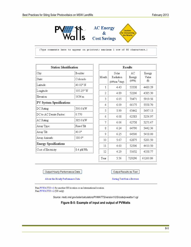
Best Practices for Siting Solar Photovoltaics on MSW Landfills February 2013
B-5
Source: rredc.nrel.gov/solar/calculators/PVWATTS/version1/US/code/pvwattsv1.cgi
Figure B-5: Example of input and output of PVWatts

Best Practices for Siting Solar Photovoltaics on MSW Landfills February 2013
B-6
Solar Decision Tree
The Solar Decision Tree is designed to guide users through a three-phase process to assess sites, including Municipal Solid Waste (MSW) landfills for redevelopment with solar PV. Users navigate the decision tree by responding to questions in the "Evaluation" boxes. Depending on the response, the user is directed to the next criteria or alerted to a potential obstacle by the "Flags." The user is directed to the next process step by "Arrows." The solar PV decision tree is located at: http://epa.gov/renewableenergyland/docs/solar_decision_tree.pdf. See Section II.5 for landfill-specific considerations.
Source: EPA
Figure B-6: Solar Decision Tree

Best Practices for Siting Solar Photovoltaics on MSW Landfills February 2013
C-1
Appendix C: Financing and Procurement Options
Owner and Operator Financing The owner/operator financing structure is characterized by a single entity with the financial strength to fund all of the solar project costs and, if a private entity, sufficient tax appetite to utilize all of the project’s tax benefits. Private owners/operators typically establish a special purpose entity (SPE) that solely owns the assets of the project. An initial equity investment into the SPE is funded by the private entity using existing funds and all of the project’s cash flows and tax benefits are utilized by the entity. This equity investment is typically matched with debt financing for the majority of the project costs. Project debt is typically issued as a loan based on the owner/operators’ assets and equity in the project. In addition, private entities can utilize any of federal tax credits offered. For public entities that choose to finance, own and operate a solar project, funding can be raised as part of a larger, general obligation bond, as a stand-alone tax credit bond, through a tax-exempt lease structure, bank financing, grant and incentive programs, internal cash or some combination of the above. Certain structures are more common than others and grant programs for solar programs are on the decline. Regardless, as tax-exempt entities, public entities are unable to benefit directly from the various tax credit based incentives available to private companies. This has given way to the now common use of third party financing structures such as the Power Purchase Agreement (PPA) described below.
Third Party Developers with Power Purchase Agreements (PPA) Since many project site hosts do not have the financial or technical capabilities to develop a capital intensive project, many times they turn to third-party developers (and/or their investors). In exchange for access to a site through a lease or easement arrangement, third-party developers will finance, develop, own and operate solar projects utilizing their own expertise and sources of tax equity financing and debt capital. Once the system is installed, the third-party developer will sell the electricity to the site host or local utility via a power purchase agreement (PPA), a contract to sell electricity at a negotiated rate over a fixed period of time. The PPA typically will be between the third-party developer and the site host if it is a “behind the meter” retail transaction or directly with an electric utility if it is a wholesale transaction. Site hosts benefit by either receiving competitively priced electricity from the project via the PPA or land lease revenues for making the site available to the solar developer via a lease payment. This lease payment can take on the form of either a revenue sharing agreement or an annual lease payment. In addition, third-party developers are able to utilize federal tax credits. For public entities, this arrangement allows them to utilize the benefits of the tax credits (low PPA price, higher lease payment) while not directly receiving them. The term of a PPA typically vary from 20-25 years.
Third Party “Flip” Agreements The most common use of this model is a site host working with a Third Party Developer who then partners with a tax-motivated investor in a special purpose entity that would own and operate the project. Initially, most of the equity provided to the SPE would come from the tax investor and most of the benefit would flow to the tax investor (as much as 99 percent). When the tax investor has fully monetized the tax benefits and achieved an agreed upon rate of return, the allocation of benefits and majority ownership (95 percent) would “flip” to the site host (but not within the first five years). After the flip, the site host would have the option to buy out all or most of the tax investor’s interest in the project at the fair market value of the tax investor’s remaining interest. A “flip” agreement can also be signed between a developer and investors within an SPE, where the investor would begin with the majority ownership. Eventually, the ownership would flip to the developer once investors’ return is met.

Best Practices for Siting Solar Photovoltaics on MSW Landfills February 2013
C-2
Hybrid Financial Structures As the solar market evolves, hybrid financial solutions have been developed in certain instances to finance solar projects. A particular structure, nicknamed “The Morris Model” after Morris County, New Jersey, combines highly rated public debt, a capital lease and a PPA. Low-interest public debt replaces more costly financing available to the solar developer and contributes to a very attractive PPA price for the site hosts. New Markets Tax Credits have been combined with PPAs and public debt in other locations, such as Denver and Salt Lake City.
Solar Services Agreement and Operating Lease The Solar Services Agreement (SSA) and Operating Lease business models have been predominately used in the municipal and cooperative utility markets due its treatment of tax benefits and the rules limiting Federal tax benefit transfers from non-profit to for-profit companies. Under IRS guidelines, municipalities cannot enter capital leases with for-profit entities when the for-profit entities capture tax incentives. As a result, a number of business models have emerged as a work around to this issue. One model is the “Solar Services Agreement” wherein a private party sells “solar services” (i.e., energy and RECs) to a municipality over a specified contract period (typically long enough for the private party to accrue the tax credits). The non-profit utility typically purchases the solar services with either a one-time up-front payment equal to the turn-key system cost minus the 30 percent Federal tax credit, or may purchase the services in annual installments. The municipality may buyout the system once the third party has accrued the tax credits, but due to IRS regulations, the buyout of the plant cannot be included as part of the Solar Services Agreement (i.e., the SSA cannot be used as a vehicle for a sale and must be a separate transaction). Similar to the SSA there a variety of lease options that are available to municipalities that allow the capture of tax benefits by 3rd party owners, which result in a lower cost to the municipality. These include an operating lease for solar services (as opposed to an equipment capital lease), and a complex business model called a “sales/lease-back”. Under the sales/lease-back model, the municipality develops the project and sells it to a 3rd party tax equity investor who then leases the project back to the municipality under an operating lease. At the end of the lease period, and after the tax benefits have been absorbed by the tax equity investor, the municipality may purchase the solar project at Fair Market Value.
Sale/Lease Back In this widely accepted model, the public or private entity would install the PV system, sell it to a tax investor and then lease it back. As the lessee, they would be responsible for operating and maintaining the solar system as well as have the right to sell or use the power. In exchange for use of the solar system, the public or private entity would make lease payments to the tax investor (the lessor). The tax investor would have rights to federal tax benefits generated by the project and the lease payments. Sometimes, the entity is allowed to buy back the project at 100 percent fair market value after the tax benefits are exhausted.
Community Solar Gardens The concept of “Community Solar” is one in which the costs and benefits of one large solar project are shared by a number of participants. A site owner may be able to make the land available for a large solar project which can be the basis for a community solar project. Ownership structures for these projects vary but the large projects are typically owned or sponsored by a local utility. Community Solar Gardens are distributed solar projects wherein utility customers have a stake via a pro-rated share of the project’s energy output. This business model is targeted to meet demand for solar projects by customers who rent/lease homes or business, do not have good solar access at their site, or do not want to install solar system on their facilities. Customer pro-rated shares of solar projects are acquired through a long-term transferrable lease of one or more modules, or they subscribe to a share of the project in terms of a specific level of energy output or the energy output of a set amount of capacity. Under the customer lease option, the customer receives a billing credit for the number of kWh their pro-rated share of the solar project produces each month; it is also known as “virtual net-metering”. Under the customer subscription option, the customers typically pay

Best Practices for Siting Solar Photovoltaics on MSW Landfills February 2013
C-3
a set price for a block of solar energy (i.e., 100 kWh per month blocks) from the community solar project. Other models include monthly energy outputs from a specific investment dollar amount, or a specific number of modules. Community solar garden and customer subscription-based projects can be solely owned by the utility, owned solely by Third Party Developers with facilitation of billing provided by the utility, or may be a joint venture between the utility and a Third Party Developer leading to eventual ownership by the utility after the tax benefits have been absorbed by the Third Party Developer. There are some states that offer solar incentives for community solar projects, including Washington State (production incentive) and Utah (state income tax credit). Community Solar is known as Solar Gardens depending on the location (e.g. Colorado).

Best Practices for Siting Solar Photovoltaics on MSW Landfills February 2013
D-1
Appendix D: References
Chapter 1 EPA, Municipal Solid Waste in the United States: 2009 Facts and Figures. EPA530-R-10-012. December 2010. http://www.epa.gov/osw/nonhaz/municipal/pubs/msw2009rpt.pdf EPA OSWER Center for Program Analysis. Siting Clean and Renewable Energy on Contaminated Lands and Mining Sites. Factsheet. Undated. EPA. RE-Powering America’s Land: Siting Renewable Energy on Potentially Contaminated Land and Mine Sites. Anywhere the Sun Shines: Developing Solar Energy on Contaminated Land. October 2009. Suflita, J.M., Gerba, C.P., Ham, R.K., Palmisano, A.C., Rathje, W.L., Robinson, J.A. The World’s Largest Landfill: A Multidisciplinary Investigation. Environmental Science and Technology 26.8 (1992): 1486-1495. US. Department of Energy, National Renewable Energy Laboratory. 2006. Power Technologies Energy Data Book, Fourth Edition. Table 12.1. Available at: http://www.nrel.gov/analysis/power_databook. Annual Electricity Generation (kWh) Based on 1 MW Capacity: U.S. Department of Energy, National Renewable Energy Laboratory. 2009. A Performance Calculator for Grid‐Connected PV Systems. Data accessed for average annual solar radiation (kWh/m2/day) for Portland, OR (Class 3), Minneapolis, MN (Class 4) Los Angeles, CA (Class 5), and Alamosa, CO (Class 6). Available at: http://www.nrel.gov/rredc/pvwatts/
Chapter 2 Commission File Number 1-14267. Annual Report Pursuant to Section 13 or 15(d) of the Securities and Exchange Act of 1934, for the fiscal year ended December 31, 2009. Republic Services, Inc.. Department of Health and Human Services, Agency for Toxic Substances and Disease Registry. Landfill Gas Primer: An Overview for Environmental Health Professionals. November 2001. RCRA Orientation Manual 2008: Resource Conservation and Recovery Act. (2008). EPA. p II-11. Solid Waste Disposal Facility Criteria: Technical Manual. (1993). EPA530-R-93-017. EPA. Accessed April 22, 2012: http://www.epa.gov/waste/nonhaz/municipal/landfill/techman/index.htm Solid Waste Disposal Facility Criteria: Technical Manual (Subpart F: Closure and Post-Closure). (1993). EPA530-R-93-017. EPA. Accessed April 22, 2012: http://www.epa.gov/waste/nonhaz/municipal/landfill/techman/index.htm. Waste – Non-Hazardous Waste – Municipal Solid Waste.” EPA. Accessed April 22, 2012: http://www.epa.gov/osw/nonhaz/municipal/landfill.htm.
Chapter 3 US Solar Market Insight 2010 Year-end Review.” Solar Energy Industries Association. Accessed November 15, 2011: www.seia.org/cs/research/SolarInsight
Chapter 4 Bonaparte, R.; Gross, B.; Daniel, D.; Koerner, R.; Dwyer, S. (2004). Technical Guidance for RCRA/CERCLA Final Covers. EPA/540-R-04-007. Washington, DC: U.S. Environmental Protection Agency, Office of Solid Waste and Emergency Response. Accessed April 23, 2012: http://nepis.epa.gov/Exe/ZyPURL.cgi?Dockey=P10074PP.txt. Denholm, P.; Margolis, R.M. (2008). “Land Use Requirements and the Per-Capita Solar Footprint for Photovoltaic Generation in the United States.” Energy Policy (36); pp. 3531–3543 “Hartford Solar Landfill Project.” Center for Public Environmental Oversight, Accessed January 18, 2013: http://www.cpeo.org/pubs/HartfordSolar.pdf

Best Practices for Siting Solar Photovoltaics on MSW Landfills February 2013
D-2
“Amherst, Massachusetts: Impediments to Solar Installations on Closed Landfills.” Center for Public Environmental Oversight. Accessed January 18, 2013: http://www.cpeo.org/pubs/AmherstSolar.pdf El-Fadel, M.; Khoury, R. (2000). “Modeling Settlement in MSW Landfills: a Critical Review.” Critical Reviews in Environmental Science and Technology (30:3); pp. 327-361. Print. Institutional Controls: A Guide to Planning, Implementing, Monitoring, and Enforcing Institutional Controls at Contaminated Sites (Interim Final). (2010). EPA/540-R-09-001. Washington, DC: U.S. Environmental Protection Agency, Office of Solid Waste and Emergency Response. Accessed April 23, 2012: http://www.epa.gov/superfund/policy/ic/pdfs/PIME-IC-Guidance-Interim.pdf. “Solar Map.” National Renewable Energy Laboratory. Accessed August 24, 2011: www.nrel.gov/gis/solar.html. Solid Waste Disposal Facility Criteria: Technical Manual. (2003). EPA/530-R-93-017. Washington, DC: U.S. Environmental Protection Agency, Office of Solid Waste and Emergency Response. Accessed April 23, 2012: http://www.epa.gov/waste/nonhaz/municipal/landfill/techman/index.htm. Solid Waste Disposal Facility Criteria: Technical Manual. (1993). EPA/530-R-93-017. Washington, DC: U.S. Environmental Protection Agency, Office of Solid Waste and Emergency Response. Accessed April 23, 2012: http://www.epa.gov/waste/nonhaz/municipal/landfill/techman/index.htm. Stormwater O&M Fact Sheet: Preventative Maintenance. (1999). EPA/832-F-99-004. Washington, DC: U.S. Environmental Protection Agency, Office of Water. Accessed April 23, 2012: http://nepis.epa.gov/Exe/ZyPURL.cgi?Dockey=200044A0.txt.
Agrawal, M., Bolman, C. et. al. (2012) Photon Consulting. Solar Annual 2012: The Next Wave; p. 24. Print.
Chapter 5 Bonaparte, R.; Gross, B.; Daniel, D.; Koerner, R.; Dwyer, S. (2004). Technical Guidance for RCRA/CERCLA Final Covers. EPA/540-R-04-007. Washington, DC: U.S. Environmental Protection Agency, Office of Solid Waste and Emergency Response. Accessed April 23, 2012: http://nepis.epa.gov/Exe/ZyPURL.cgi?Dockey=P10074PP.txt. El-Fadel, M.; Khoury, R. (2000). “Modeling Settlement in MSW Landfills: a Critical Review.” Critical Reviews in Environmental Science and Technology (30:3); pp. 327-361. Print. Sharma, H.D.; De Ariban, M. (2007). “Municipal Solid Waste Landfill Settlement: Postclosure Perspectives.” Journal of Geotechnical and Geoenvironmental Engineering (133:6); pp. 619-629. Print.
Chapter 6 Sharma, H.D.; De Ariban, M. (2007). “Municipal Solid Waste Landfill Settlement: Postclosure Perspectives.” Journal of Geotechnical and Geoenvironmental Engineering (133:6); pp. 619-629. Print. Standard Guidelines for the Installation of Urban Stormwater Systems. (2006). ASCE Standard No. 46-05. Reston, VA: American Society of Civil Engineers. Print. Task Committee of the Urban Water Resources Research Council of the American Society of Civil Engineers and the Water Environment Federation. (1993). Design and Construction of Urban Stormwater Management Systems. ASCE Manuals and Reports on Engineering Practice No. 77, WEF Manual of Practice FD-20. New York, NY: American Society of Civil Engineers. Print.
Chapter 7 Livingston, E.H.; Shaver, E.; Skupien, J.J. (1997). Operation, Maintenance, & Management of Stormwater Management Systems. Work performed by Watershed Management Institute, Inc., Ingleside, MD. Washington, DC:

Best Practices for Siting Solar Photovoltaics on MSW Landfills February 2013
D-3
U.S. Environmental Protection Agency, Office of Water. Accessed April 23, 2012: http://www.stormwater.ucf.edu/research/stormwaterOMM/stormwateromm.pdf.