Embed Size (px)
Citation preview
Best Practices for Efficient Liquid Chromatography (LC) Operations
Making the Most of Your LC SystemMia Summers and Andreas Kugler
F E B R U A RY 2 0 1 9
Spon s o r ed b y
This custom ebook is sponsored by Agilent Technologies and presented in partnership with LCGC.
Making Good LC Methods Even BetterWilliam Long
Taking Advantage of LC Column CharacteristicsAnne Mack

Maximize Your LC and LC/MSD Workflow EfficiencyAgilent InfinityLab is an optimized portfolio of LC instruments, mass selective detectors, columns, and supplies designed to work together in perfect harmony. From routine analysis to cutting-edge research, InfinityLab can help your lab reduce costs and run more efficiently than ever.
With InfinityLab products, plus Agilent OpenLab software and Agilent CrossLab services, we provide end-to-end solutions to make your lab more productive every day.
Learn more about ensuring the best analytical outcomes: www.agilent.com/chem/infinitylab
© Agilent Technologies, Inc. 2019

INTRODUCTION
Getting better, faster, more reliable results is a top-of-mind concern at busy
laboratories, many of which are often seeking new ways to increase efficiency.
What new techniques are available for ensuring the most reliable results and
more efficient laboratory operations?
This ebook on Best Practices for Efficient Liquid Chromatography (LC) Operations covers some
straightforward techniques that could immediately increase efficiency in the laboratory.
First, Mia Summers and Andreas Kugler describe how proper preventative maintenance can
avoid many common problems, and a methodical approach to dealing with them can reduce
the time and difficulty involved in diagnosing and fixing issues. This covers everything from
proper column selection to issues with autosamplers and injectors to signs of contaminated
solvent.
Next, Agilent Technologies’s Anne Mack reviews analytical method development challenges
and explores the importance of keeping the objectives of the separation in mind during method
development. She also describes which physical characteristics must be considered when
choosing an LC column, including particle pore size, particle technology, and the actual particle
size itself.
Readers will also learn from William Long, also of Agilent Technologies, how with existing
methods, simple adjustments, such as incorporating new column technologies, can often
result in enhanced resolution and better peak shape and ensure that the method will perform
reproducibly and provide reliable—even improved—results.

4 FEBRUARY 2019 | LCGC SPONSORED CONTENT
Diagnosing Problems
Method Development
LC Columns
SPONSORED CONTENT
OverviewAlthough modern liquid chromatography (LC) is a mature technology, problems can still arise during analysis. When challenges occur, it can be extremely frustrating. This can be especially true when deal-ing with system failures such as leaks, bubbles, and clogs. Moreover, diagnos-ing chromatographic problems can be a time-consuming experience. Fortunately, proper preventative maintenance can avoid many common problems, and a methodical approach to dealing with them can reduce the time and difficulty involved in diagnosing and fixing issues.
The Mobile PhaseHaving clean mobile phase is essential for ensuring the LC system runs reliably and reproducibly.
While it may be tempting to cut corners, using high-performance liquid chromatog-raphy (HPLC) or mass spectrometry (MS)-grade solvents will save laboratories time and money in the long run by reducing
system contamination, unexpected peaks, and repeat analysis.
Signs of a contaminated solvent can in-clude ghost peaks, baseline drift, climbing backpressure, frequent degasser failures, or unusually short column lifetimes. Of those, ghost peaks are often the first sign of solvent contamination. They show up as peaks that seem to move around the chromatogram or appear and disappear. Ghost peaks can be a result of low-level mobile phase or sample-related impurities that build up in the system and are eluted inconsistently at different times, some-times triggered by the injection solvent or gradient conditions. They can also be negative peaks caused when a continuous baseline of a contaminant in the mobile phase is interrupted by the injection of a sample that offsets the wavelength detec-tion of the background contaminant.
Some ghost peaks can be attributed to the method conditions rather than sys-tem or mobile phase contamination. The most likely cause is that the run time is
Making the Most of Your LC SystemMia Summers and Andreas Kugler
Best Practices for Efficient LiquidChromatography
Imag
es u
nder
lice
nse
from
sto
ck.a
dobe
.com

5 FEBRUARY 2019 | LCGC SPONSORED CONTENT
Diagnosing Problems
Method Development
LC Columns
too short for the sample, and some late eluting components from each injection are showing up in subsequent chromato-grams. When all components in a sample mixture are not properly eluted off the column, these components remain on the column for slow and inconsis-tent elution over subsequent injec-tions. If analysts suspect this is the case, they should wash the column with a high percent-age of the organic component of a re-versed-phase mobile phase and then flush the column with several blank runs with method conditions. Finally, a single injec-tion with an extended run time should be performed to verify that all the peaks are eluted within the programmed run time.
Small particles in the mobile phase can cause serious problems for LC compo-nents, from a malfunctioning degasser to damaged pump seals or even pistons. A common source of particulates comes from contamination of buffer salts, or precipitation due to inattentiveness to solvent conditions. When using buffers on a gradient system, one should never drive the organics so high that the buffers are no longer soluble.
Any mobile phase component prepared with dissolved solids should be passed through a filter with 0.45-μm pores or smaller. Care should be taken that the
filter membrane material is compatible with the solvent. If mobile phases contain-ing dissolved solids or salts have been run through the LC system, then flushing
with water after the analysis is completed will be necessary to ensure they are removed. Simply switching to a differ-ent solvent system for the next analysis could result in precip-itation. When switch-ing solvent systems, it is also important to maintain miscibility at
all times. It is best practice to step to an intermediate solvent that is miscible with mobile phases being used to the desired mobile phase. Keep in mind that the pres-ence of salt can change miscibility. For instance, water and isopropanol (IPA) are miscible when pure, but not in high salt concentrations.
Another source of particulates are mi-crobes growing in the aqueous mobile phase bottles. In multi-solvent systems, it is customary to mix aqueous and organic components at the time of analysis us-ing an integrated solvent proportioning valve. This simplifies the analyst’s work, but increases the risk of microbial growth in the aqueous mobile phase bottle and line. Solutions with buffers may be an even more microbe-friendly environment. Microbial particulates cannot always be seen. They can collect in the inlet frit of a column, causing high backpressure
Best Practices for Efficient LiquidChromatography
“Small particles in the mobile phase can cause serious problems for LC components, from a malfunctioning degasser to damaged pump seals or even pistons.”

6 FEBRUARY 2019 | LCGC SPONSORED CONTENT
Diagnosing Problems
Method Development
LC Columns
and ghost peaks. They are also often smaller than the column inlet frits pore size, passing through and collecting onto the column bed. Again, an inline filter will help, but microbial growth can be pervasive throughout an LC system once introduced and difficult to remove after the fact. To avoid the challenging trouble-shooting of microbial particulate, it is best to take steps to prevent introduction into the system. Adding a small amount of organic to the aqueous mobile phase (and adjusting the method conditions slightly to compensate) can prevent microbial growth. Protecting the mobile phase from light using amber bottles will inhibit the growth of cyanobacteria. Even with these steps, it is a good idea to change out any aqueous mobile phase with fresh water in a clean bottle every couple of days. When-ever the system is left untended, flush the water line with the organic solvent used in reversed-phase methods. The degasser is another area prone to microbial growth if left with water in it. Always be sure the lines are not stored in 100% aqueous and stored in organic solvent when not in use.
Solvent evaporation will change the composition of a premixed mobile phase, in addition to being a safety concern. Properly closed solvent bottles will prevent this, but the bottle must not be completely sealed to avoid vacuum form-ing. This can be as simple as a cap with a hole drilled through it just big enough for the line, or ideally a commercially designed cap with an integrated filter and vent system, such as InfinityLab Stay Safe Caps by Agilent.
There are times when one must flush out some or all of the system for non-use, storage, or troubleshooting. If salts are present in the system, then water is the obvious first choice to dissolve salts and remove them from the system. Once the presence of salts can be ruled out, then IPA works well as a final flush for the system. It is miscible with most common LC solvents, both normal and reverse phase. Its relatively high viscosity and low surface tension make it a good choice for dislodging bubbles. It has a low vapor pressure, which means components will not dry out as quickly. It will also suppress microbial growth.
The PumpMany of the problems frequently encoun-tered with LC systems can be traced to the pump. Indeed, pumps are expected to provide a continuous and steady flow of liquid at hundreds of bar pressure. The pressure produced by the pump should be consistent. Monitoring a system’s pres-sure provides a valuable diagnostic tool. A steadily climbing back pressure is often an indication that a module component is being fouled, usually by particulates in-troduced into the LC system. Particulates can also show up as frequent failures of the degasser, or premature column death. As mentioned, the mobile phase is the most common culprit, but once the pres-sure has begun to climb, removing the obstruction becomes another priority.
When tracking the source of increased back pressure, start downstream at the detector. Because the column is typically
Best Practices for Efficient LiquidChromatography

7 FEBRUARY 2019 | LCGC SPONSORED CONTENT
Diagnosing Problems
Method Development
LC Columns
the strongest contributor to the system’s back pressure, it is always a challenge to differentiate between the column being the root cause or other parts in the system. For troubleshooting, therefore, the column always should be removed and replaced by a “restriction capillary” (e.g., Agilent p/n 5022-2159 Stainless Steel Capillary, 0.12 mm ID, 2000 mm length). This capillary provides a certain back pressure for reliable troubleshooting. It is always good to know what is the normal back pressure range of each system. Disconnect tub-ing to components mov-ing steadily upstream toward the degasser until the backpressure drops. The segment that causes the pressure to drop back to normal when disconnected is the culprit.
Over a series of runs, the system pres-sure should not change drastically, although a small ripple (sometimes called “delta”) is normal. Advanced LC systems, such as the Agilent InfinityLab LC series, allow analysts to monitor the pump ripple. While the ripple will vary from system to system and method to method, a drastic change or deviation from the expected value is a strong indication of a problem with the pump. As a best practice, it is good to be familiar with and document the expected pressures for your LC system to quickly identify any deviations.
Changes in pressure can sometimes go unnoticed. After all, modern LC pumps
are reliable and steady most of the time, and can now be run remotely once set up. Sometimes, other signals are the first sign of a pump problem. If the detection base-line becomes noisy or retention times start to shift noticeably, it is time to check on the pump.
Pump problems can most commonly be traced to one of three common causes: bubbles in the pump, pump seals, or the
pump valves. An air bubble can typically be fixed by purging with an organic solvent. Flushing the system to remove air bubbles is best done with IPA due to its high viscos-ity and with a restriction capillary installed to create a certain back pressure. The column should, of course, be uninstalled.
Modern LC pumps offer special instrument settings (piston stroke) or even automated flushing or purging procedures that can be used. Care should be taken not to exceed system pressures when using or switching solvents to/from IPA. In a multi-line systems, flush all the lines simultaneously. This action may solve the problem.
Once air bubbles are ruled out, if system problems persist, one can examine the seals or valves for wear and tear or damage. A dirty seal or malfunctioning valve often mani-fests as unusual pressure ripple affecting baselines, or unexpected lower or higher system pressures and shifting retention times. Salt buffers, harsh solvents, and pH extremes can be hard on seals, which
Best Practices for Efficient LiquidChromatography
“Pump problems can most commonly be traced to one of three common causes: bubbles in the pump, pump seals, or the pump valves.”

8 FEBRUARY 2019 | LCGC SPONSORED CONTENT
Diagnosing Problems
Method Development
LC Columns
may require more frequent replacement. While requiring some disassembly, it is a relatively quick job to replace a seal or valve on most systems. Many manufactur-ers provide pump head maintenance kits with all the replaceable components and detailed instructions. It is important to use the proper supplies that are designated for the instrument or pump module. Quick Ref-erence Guides can offer quick identification of parts that go with specific modules.
Figure 1 is a diagram of a traditional Agi-lent HPLC system pump head. The seals are
shown in red. It is a good idea to establish a regular replacement schedule instead of waiting for a problem to occur, especially in a QA/QC environment where the instrument is under heavy use and system downtime must be kept at a minimum. Seals come in different materials. Be sure to use a material that is compatible with your solvents.
The purge valve is a very useful tool for flushing and priming the pump. The Agilent 1200 series LC systems have a purge valve containing a PTFE frit that protects the rest of the system from particulates,
Best Practices for Efficient LiquidChromatography
FIGURE 1: Traditional pump head.

9 FEBRUARY 2019 | LCGC SPONSORED CONTENT
Diagnosing Problems
Method Development
LC Columns
which is a good feature to protect your LC investment. However, over time, this PTFE frit can become clogged. When purging the system, most of the pressure drop will be across this frit. If the pressure exceeds 10 bar with water at 5 mL/min, it is time to change the frit. The frit is easily accessible and quick to replace (see Fig-ure 2). As with the pump seals, it makes more sense to replace the frit on a regular basis rather than wait for a problem.
As mentioned, shifting retention times can result from problems in the pump, but if the pump appears to be functioning properly (and the current pump settings match the current type of solvent), the is-sue could be with the proportioning valve.
Also known as a gradient valve or solvent selection valve, it will fail over time and may need to be replaced. As with the degasser, flushing with water after us-ing mobile phases with buffer salts will lengthen the lifetime of the valve. One way of determining if the selection valve is the source of the problem is to premix the mobile phase solvents used in an isocratic method and bypass the valve and directly connect into the pump head. Use only one line or pump head at a time to confirm a standard separation. Moving the solvent source then from one solvent line or pump head to another is a good way to isolate the problem.
Best Practices for Efficient LiquidChromatography
FIGURE 2: Replacing PTFE frits in the purge valve.
10 FEBRUARY 2019 | LCGC SPONSORED CONTENT
Diagnosing Problems
Method Development
LC Columns
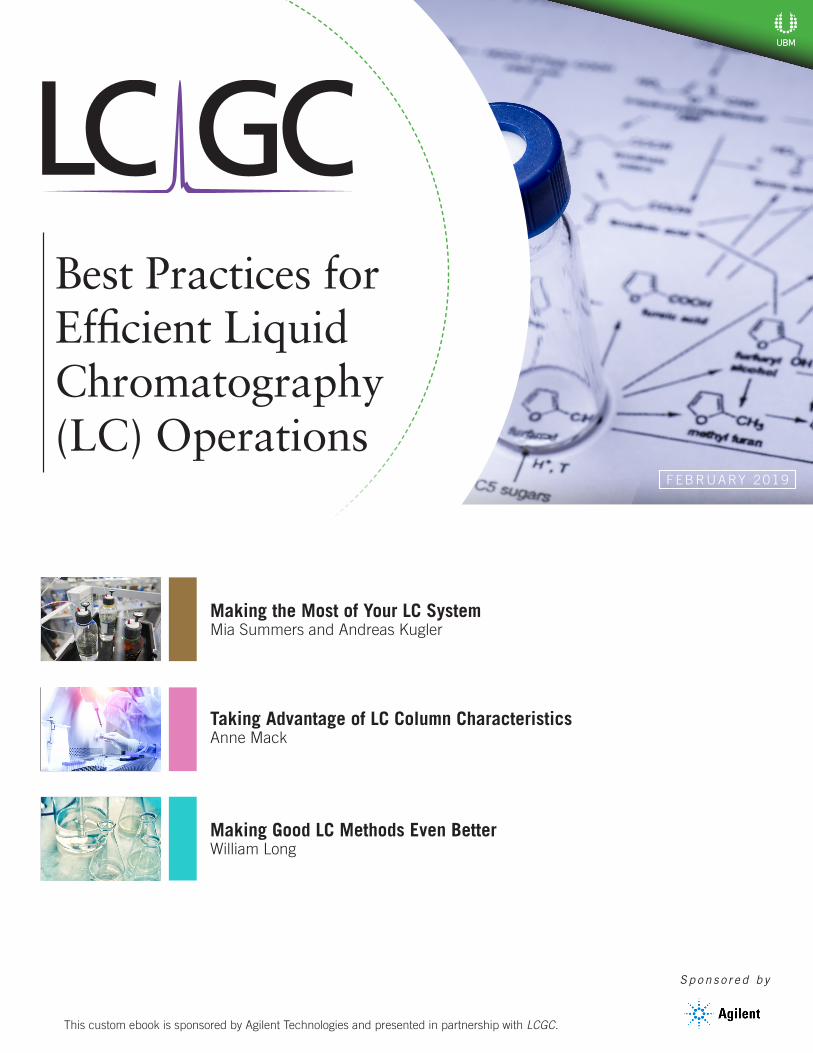
The Autosampler and InjectorAutosamplers and injectors have become complex pieces of equipment that can be the source of some chromatographic is-sues. A poor seal between the needle and needle seat can cause carryover, resulting in ghost peaks or irreproducible quantita-tion. The needle seat and needle should be seen as one “functional” piece and in case of trouble, must always be replaced at the same time. A damaged needle can damage the needle seat; if only the
needle seat is replaced, it will instantly become damaged by the old needle and vice versa. In case of blockages at the needle and needle seat, it is important to check for the root cause. Debris could be released from some other part upstream (e.g., vial caps or plate seals).
Best Practices for Efficient LiquidChromatography
FIGURE 3: Injection valve.
Agilent InfinityLab: Mak-ing Great ConnectionsLess stress, more reliable fittings
SPONSOR’S CONTENT

11 FEBRUARY 2019 | LCGC SPONSORED CONTENT
Diagnosing Problems
Method Development
LC Columns
Best Practices for Efficient LiquidChromatography
Fitting Connections
January 29, 2019
1
Poor Fitting Connections• will broaden or split peaks or cause tailing
• will typically affect all peaks, but especially early eluting peaks
• can cause of carry-over
min0 0.1 0.2 0.3 0.4
mAU
020406080
100120140
One bad connection!
min0 0.1 0.2 0.3 0.4
mAU
0306090
120150180210 Fixed!
Too longBad
Good
Ferrule cannot seat properly→ leakBad
Mixing chamber→ dead volume
Too short
Properly fitted tubing, no dead volume
FIGURE 4: Correct and incorrect fitting connection.
Figure 3 shows exploded and cutaway views of an injection valve. The rotor seals will wear over time or be damaged by particulates. Worn rotor seals can cause sample carryover and irreproducible injec-tions and should be replaced. They come in a variety of materials. Analysts should be sure to choose the correct material for the solvent and/or pH. Instrument manufactur-ers will often provide kits containing all the consumable parts for autoinjector modules in a single package.
The ColumnPoor efficiency might be traced to poor col-umn choice or an aging column developing
voids. But, it can also result from having incorrectly sized capillary tubing. The small-est diameter and shortest tubing suitable for the system should be used. Capillary tubing that is too long or has an inner diameter (ID) that is too wide can cause extra-column volume, which will contribute to the broadening of the peaks before they even reach the column.
Different manufacturers may use different types of fittings. Using the wrong fitting can damage the instrument or result in leaks or tailing peaks. The most common are Swagelok-style with a 10-32 thread and one or more tapered ferrules. When install-
12 FEBRUARY 2019 | LCGC SPONSORED CONTENT
Diagnosing Problems
Method Development
LC Columns
ing a fitting for the first time, the tubing should be pushed all the way in before tightening the fitting. Otherwise, the gap will create peak broadening, usually in the form of consistent tailing of peaks, even those that are less retained. Figure 4 shows correct and incorrect installation of fittings. However, newer column connec-
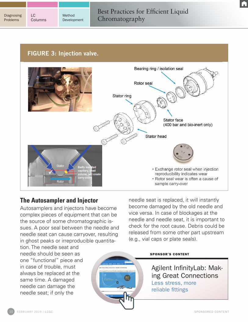
tion technology avoids these problems. For instance, the Agilent InfinityLab Quick Connect Fitting addresses these issues with a spring load function that automati-cally adapts to the receiving port depth of the column (see Figure 5).
When experiencing problems, it is also critical to examine the column con-
nection fitting because a damaged fitting will also impair the receiving port of the new column. When standard stainless-steel fit-tings are used, use a new capillary when changing to a new column because either the new column will
Best Practices for Efficient LiquidChromatography
Agilent InfinityLab Stay Safe Caps – Reduction of Solvent Evaporation
SPONSOR’S CONTENT
FIGURE 5: Agilent InfinityLab Quick Connect and Quick Turn Fittings.

13 FEBRUARY 2019 | LCGC SPONSORED CONTENT
Diagnosing Problems
Method Development
LC Columns
have a slightly different swage depth or the worn fitting on the old capillary will damage the new column fitting. In addition, take care not to overtighten the column connection fittings (typically the standard stainless steel fittings). Ap-plying excessive force can damage the fittings and the column receiving ports and cause leaks. Users might then try to apply even more force to achieve a leak tight connection. Sooner or later, the column will get replaced, either because the leak persists or simply because the column reached the end of its lifetime.
Again, new removable fittings like the Agilent InfinityLab Quick Connect Fit-tings address these issues with features like the spring load function to automati-cally adapt to different port depths and have the ability to replace ferrules in case of damage.
A variety of issues can arise with the column itself. One issue that was already mentioned is that columns can develop voids through rough handling or age. If the peaks coming out on or near the void are broad or tailing, and extra-column broad-ening has been ruled out, it may be time to change the column. High backpressure that is not attributed to the system may be due to column contamination if the column has been heavily used or many insoluble components such as for-mulation excipients have been injected onto the col-umn. Microbial contamina-tion can also build up on the column bed. In all of
these cases, the column may need to be replaced with a new one. Routine preven-tative maintenance on the system and the addition of sample preparation techniques such as filtering samples or solid phase extraction may be considered to reduce costly troubleshooting and downtime of the LC system.
The DetectorThere are only two components likely to require attention in a UV detector: the lamp and the flow cell. Most lamps contain deu-terium gas, which will leak over time. Since method response is based on the ratio of peaks, a weakening bulb may not be obvi-ous at first, however the baseline noise will appear to grow relative to the peaks over time. Poor detection signal or a noisy base-line are good signs that the lamp is due for replacement. When changing the lamp, be sure to avoid touching the bulb.
Flow cells are generally maintenance free, but problems can arise. If using a second detector downstream, be cogni-zant of the additional back pressure it cre-ates. Too much back pressure in the first flow cell can rupture it. For these applica-tions, high-pressure cells are available. Cells can also become fouled and must be
Best Practices for Efficient LiquidChromatography
Sample Preparation WhitepaperMake the most out of your LC system. Is your “good enough” sample preparation really good enough?
SPONSOR’S CONTENT

14 FEBRUARY 2019 | LCGC SPONSORED CONTENT
Diagnosing Problems
Method Development
LC Columns
Andreas Kugler Product Support Engineer LC Supplies Agilent Technologies
flushed clean.Newer technologies with RFID tags
(such as Agilent InfinityLab flow cells and lamps) can help track usage and preventa-tively plan replacement to keep systems at maximal uptime and improve lab opera-tional efficiency.
ConclusionSeveral common problems can arise while using an LC system, however, good main-tenance and preventative measures will help systems run for years without major problems. Avoiding microbial growth; regularly replacing valves, seals and frits; making proper column connections and maintaining good mobile phase practice will go a long way toward avoiding annoy-ing, time-consuming, and expensive sys-tem downtime. It is also helpful to have some staff members trained specially for troubleshooting. Customer training (such as basic and troubleshooting classes) will help them understand the special func-tionalities and operation principles of the instrument as well as how to troubleshoot problems, reduce downtime, detect po-tential problems upfront, and ensure the instruments operate correctly.
Best Practices for Efficient LiquidChromatography
Mia Summers Former LC Columns Product Manager Agilent Technologies

15 FEBRUARY 2019 | LCGC SPONSORED CONTENT
Diagnosing Problems
Method Development
LC Columns
SPONSORED CONTENT
hromatographers make numer-ous decisions during the liquid chromatography (LC) method development process, many of
which are important for developing a robust analysis. Column choice is one of those decisions and is a significant factor for a suc-cessful analysis. This manuscript will explore various column features and illustrate how choosing the appropriate LC column can improve chromatographic results, including improved resolution and peak shape via alternate selectivities, the impact of mobile phase composition and pH, and extend col-umn lifetime.
Analytical Method Development Chal-lenges and Defining ObjectivesToday, several challenges can make high-performance liquid chromatography (HPLC) method development more confusing than ever. One significant challenge is choosing the mode of chromatography and the right HPLC column to use. Since chromatogra-
phers have many different chromatographic modes to choose from, the choice of which one to use can be overwhelming. However, since approximately 80% of all HPLC sepa-rations are performed by reversed phase, a good end-capped C18 phase is a good place to start. Method transfer is another chal-lenge. Many companies have laboratories all over the world and must transfer methods between them and require that the method perform as well as it did in the destination lab as it did in the original lab. In addition, contract laboratories—which are widely used in the pharmaceutical industry—may have many different HPLC instrument brands. This diversity can complicate the method transfer process because systems from different vendors can have widely different system volumes, tubing and fit-ting differences, and many other different operational characteristics. Consequently, a way to simplify the method development process is desirable.
Before actually initiating the method de-velopment process, the objectives of the separation should be addressed. Items that
Taking Advantage of LC ColumnCharacteristicsto Improve AnalysesAnne Mack
Taking Advantage of LC ColumnCharacteristics
C

16 FEBRUARY 2019 | LCGC SPONSORED CONTENT
Diagnosing Problems
Method Development
LC Columns
should be considered include:• How many peaks are likely to be present?• Will it be easy or challenging to separate
the peaks?• Are efficiency and speed (run time or
inject-to-inject cycle time) important?• What kind of instrumentation is available?• Can mobile phase gradients be used?• Are pressures above 400 bar available?• Who is going to run the routine samples?
What is their level of training?These questions, and certainly others, can
help decide the method requirements and how much effort should be put into develop-ment.
In addition to method objectives, it is important to have a few goals in mind, depending upon the application. The left
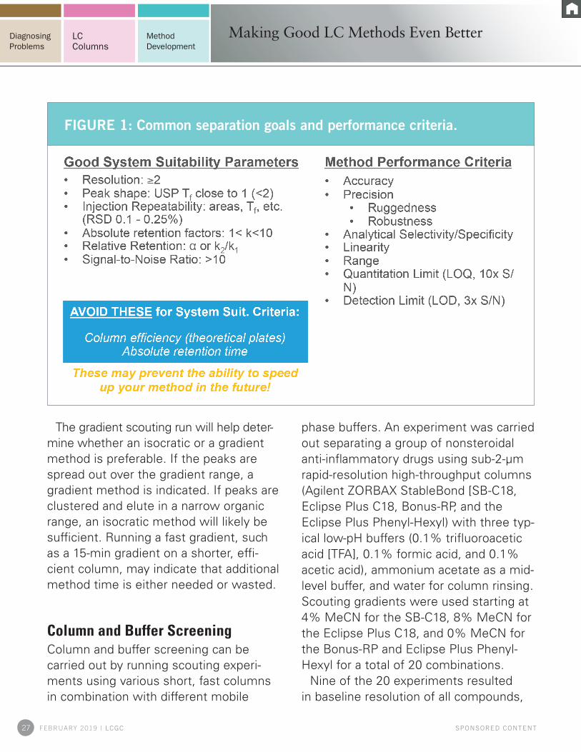
side of Figure 1 lists method goals com-mon to most applications, many of which are often included as system suitability test requirements. Resolution is one of the more important criteria in method development, especially when using nonspecific detectors like ultraviolet, evaporative light scattering detector, or fluorescence. A resolution of at least 2 is preferred, but at a resolution of 1.5, two adjacent peaks are considered baseline resolved. System suitability parameters are established during method validation, where method performance parameters, shown in the right side of Figure 1, are evaluated. When setting system suitability parameters and criteria, it is good to avoid criteria that limit the ability to modify the method in the future. For example, if efficiency or absolute
FIGURE 1: Common separation goals and performance criteria.
Taking Advantage of LC ColumnCharacteristics

17 FEBRUARY 2019 | LCGC SPONSORED CONTENT
Diagnosing Problems
Method Development
LC Columns
retention times are used as system suit-ability criteria, a modification of the method may require a full revalidation.
Method Development: Where To Begin?Once method development goals and ob-jectives have been determined, method development begins by taking advantage of the resolution equation, shown in the upper right of Figure 2. As seen in Figure 2, efficiency (N), selectivity (alpha), and retention factor (k') are the variables that
drive resolution. The scatter plot in Figure 2 shows the effect that each of these three variables have on resolution. The al-pha term, or selectivity, has a far greater effect on resolution than efficiency and retention. Therefore, during method development, changing selectivity will have the greatest impact on the separa-tion to achieve the desired resolution. Alpha or selectivity is changed by altering the chemistry of the system, either the mobile phase (composition or pH), the column bonded phase (e.g., C18, C8, phenyl-hexyl, or cyano), or both. Column
FIGURE 2: Efficiency, selectivity, and retention factor are variables that affect resolution, with selectivity having the greatest impact
Taking Advantage of LC ColumnCharacteristics

18 FEBRUARY 2019 | LCGC SPONSORED CONTENT
Diagnosing Problems
Method Development
LC Columns
temperature can also affect alpha, espe-cially if acids or bases are present.
Physical Characteristics of HPLC ColumnsMany physical characteristics must be considered when choosing an LC column before initiating method development, including particle pore size, particle technol-ogy, and the actual particle size itself.
It is important to select the optimal pore size for any HPLC analysis application. Smaller, 80–120-Å pore size column pack-ings are used for the separation of smaller molecules (i.e., molecular weights of less than 4,000). Smaller pore size columns will also maximize loading capacity and reten-tion. The slightly larger 120-Å pore size is a great choice for peptide mapping, and 300-Å pore size columns are used for larger mole-cules like intact peptides and proteins. Even larger pore sizes of 1,000–4,000 Å are used for very high molecular weight proteins.
In the earlier days of liquid chromatog-raphy, particle sizes were well above 10 μm. It was not until the early 1970s when small, totally porous silica particles were made specifically for HPLC. In the 1980s, 5-μm particles were introduced, and in the 1990s, 3.5-μm particles made faster separations possible. A column particle technology that has become popular within the last 10 years are the sub-2 μm totally porous particles used for ultrahigh-perfor-mance liquid chromatography (UHPLC) applications. However, sub-2-μm particles require specialized instrumentation to take full advantage of their capabilities.
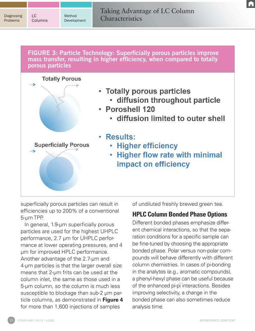
Superficially porous particles are an alternative new technology that offers substantial increases in efficiency and peak capacity over columns packed with older, conventional 5-μm particles and can be used with existing conventional HPLC systems. It is important to recognize that superficially porous particles are not magic; they obey the same chromato-graphic principles as 5-μm particles so the same method development processes can be used. Superficially porous particle shave a solid core limiting diffusion to the outer shell. Figure 3 illustrates why these particles are more efficient; shorter diffu-sion distances result in less peak broaden-ing and higher efficiency (plates) while enabling higher flow rates/faster analysis times without compromising efficiency.
The choice of particle size is somewhat driven by the complexity of the separation and therefore the resolution required. In general, smaller particle sizes are more ef-ficient. However, this efficiency comes with a price: Because pressure is proportional to the column length over the square of the particle size, higher system back pressures will be encountered as the particle size decreases. Superficially porous particles are available in three different particle sizes: 1.9 μm, 2.7 μm, and 4 μm. The choice of particle size depends on the separation requirements and the available instrumenta-tion. The overall diameter determines the pressure, so superficially porous particles operate at pressures similar to the corre-sponding totally porous particle (TPP) par-ticle size. The thickness of the porous layer determines the column efficiency: use of
Taking Advantage of LC ColumnCharacteristics
19 FEBRUARY 2019 | LCGC SPONSORED CONTENT
Diagnosing Problems
Method Development
LC Columns
superficially porous particles can result in efficiencies up to 200% of a conventional 5-μm TPP.
In general, 1.9-μm superficially porous particles are used for the highest UHPLC performance, 2.7 μm for UHPLC perfor-mance at lower operating pressures, and 4 μm for improved HPLC performance.Another advantage of the 2.7-μm and 4-μm particles is that the larger overall size means that 2-μm frits can be used at the column inlet, the same as those used in a 5-μm column, so the column is much less susceptible to blockage than sub-2 μm par-ticle columns, as demonstrated in Figure 4 for more than 1,600 injections of samples
of undiluted freshly brewed green tea.
HPLC Column Bonded Phase OptionsDifferent bonded phases emphasize differ-ent chemical interactions, so that the sepa-ration conditions for a specific sample can be fine-tuned by choosing the appropriate bonded phase. Polar versus non-polar com-pounds will behave differently with different column chemistries. In cases of pi-bonding in the analytes (e.g., aromatic compounds), a phenyl-hexyl phase can be useful because of the enhanced pi-pi interactions. Besides improving selectivity, a change in the bonded phase can also sometimes reduce analysis time.
Taking Advantage of LC ColumnCharacteristics
FIGURE 3: Particle Technology: Superficially porous particles improve mass transfer, resulting in higher efficiency, when compared to totally porous particles

20 FEBRUARY 2019 | LCGC SPONSORED CONTENT
Diagnosing Problems
Method Development
LC Columns
C18 and C8 bonded phases are a great first choice for method development. They work great from pH 2 to 9. Endcapping, or de-activation of Si-OH groups leftover on the silica surface of a column during the bond-ing process, can also affect selectivity. Many C18 and C8 bonded phases are available both endcapped and non-endcapped and can be evaluated during method develop-ment. Phenyl-hexyl is another excellent alternative phase that can be used to take advantage of pi–pi interactions with an ana-lyte and the stationary phase. The selectivity with phenyl–hexyl phases are very similar to phenyl or diphenyl columns. Other phases, like those that have a polar group embedded in the bonded phase, are also a good choice
often yielding unique selectivity for polar compounds. Cyano phases can be used for both normal as well as reversed-phase sepa-rations and bare silica phases can be used for hydrophilic interaction chromatography of very polar molecules. Pentafluorophenyl phases are also often used as an orthogonal phase for polar compounds.
To gain a more detailed understanding of the selectivity of different chemistries, bond-ed phase characterization tests are avail-able. Examples of the characterization of reversed-phase chemistries are the Tanaka Test and the Hydrophobic Subtraction Mod-el (HSM). These tests classify chemistries according to various parameters and can be used to calculate a similarity factor (Fs)
Taking Advantage of LC ColumnCharacteristics
FIGURE 4: Long lifetime with dirty samples on 2.7 μm InfinityLab Poro-shell 120 column

21 FEBRUARY 2019 | LCGC SPONSORED CONTENT
Diagnosing Problems
Method Development
LC Columns
between two columns. A small Fs indicates that two columns are very similar, while a large factor indicates that two columns are very different. When developing methods, it is useful to evaluate columns that provide different or orthogonal selectivity to improve the separation.
An example of how column selectivity can be used to enhance a separation is shown in Figure 5 for the separation of eight steroids using a methanol gradient mobile phase. With many of the phases, changes in selectivity can be seen. In addition, a reasonable separation is ob-tained, but some peaks are not resolved. On the phenyl–hexyl phase, however, all
eight steroids are baseline separated with a shorter run time than any of the other phases. There is no guarantee that any of the phases will separate all the com-pounds in all samples without additional work, but as demonstrated in Figure 5, selectivity is affected with a change in sta-tionary phase, which is very helpful early in the method development process.
Altering Selectivity with Mobile Phase pHMobile phase pH can also affect the reten-tion and selectivity of ionizable compounds. Many newer phases can operate over a wide pH range (e.g., 2–10), so pH can now
Taking Advantage of LC ColumnCharacteristics
FIGURE 5: Separation of 8 Steroids with Methanol Gradient – Having a choice of column phases enables easier method development

22 FEBRUARY 2019 | LCGC SPONSORED CONTENT
Diagnosing Problems
Method Development
LC Columns
be used to drive selectivity and improve method development by improving both retention and resolution. Figure 6 illustrates how an Agilent InfinityLab Poroshell 120 HPH-C18 2.7-μm column was used to compare selectivity at both pH 3 and pH 10 for several compounds. The scatter of the data points in this plot shows how much pH can effect selectivity. The correlation coef-ficient, R2, here referred to as the indicator of orthogonality, is very low at 0.40. Non-ionizable compounds, or those that do not ionize over the range of 3–10, elute on the light blue line, positioned at y=x. The scat-
tered data points represent compounds that changed ionization state from pH 3 to 10, affecting their retention.
Taking Advantage of LC ColumnCharacteristics
FIGURE 6: Varying mobile phase pH can offer very different selectivity, shown by the poorly correlated retention times of various analytes at pH 3 and 10

23 FEBRUARY 2019 | LCGC SPONSORED CONTENT
Diagnosing Problems
Method Development
LC Columns
Maximizing the Effect of High-Efficiency LC ColumnsTo maximize the effect of high-efficiency LC columns, one must consider data col-lection rates, injection volumes, and the effect of guard columns and fittings on system dispersion.
The data collection rate is how often the detector is recording information; lower data rates generate artificially broad and short peaks, which decrease efficiency and reso-lution. A general rule of thumb is to use a data collection rate that collects a minimum of 20 data points across the chromatograph-ic peak. Since high-efficiency separations
result in narrower peaks, data rates must be increased pro-portionately. Data rates as high as 10 to 20 Hz or more are commonly used when using high-efficiency LC columns.Injection volumes contribute to overall system volume, and therefore must be kept
Taking Advantage of LC ColumnCharacteristics
Agilent LC Column Navigator Easily find the best column for your analysis by method parameters, USP method, or compound.
SPONSOR’S CONTENT
FIGURE 7: Injection volumes contribute to overall system volume, and therefore must be kept small to preserve the performance of high-efficiency columns like Agilent InfinityLab Poroshell 120 1.9 μm columns.

24 FEBRUARY 2019 | LCGC SPONSORED CONTENT
Diagnosing Problems
Method Development
LC Columns
small to preserve the performance of high-efficiency columns. Figure 7 shows how decreasing injection volume, even while maintaining the same mass load on the column, dramatically increases ef-ficiency, even for later eluting compounds.
Since low system dispersion is necessary to maintain the high efficiency of superfi-cially porous particle columns, it is important to use sub-2-mm particle guard columns that are specially designed for use at high pres-sures especially for samples with complex or “dirty” matrices, even when using an up-front sample preparation. Analytical columns are very expensive to replace, while guard columns are not. Therefore, it is often a good idea to use a guard column to extend the life of the analytical column. When se-lecting a guard column, look for one that is compatible with the analytical column phase and does not impart additional extra-column volume to the system.
One common problem that surfaces when installing LC columns involves the fittings used to connect the column into the instru-ment. Improperly swaged fittings with col-umns can result in leaks, extra-column dead volume, poor chromatography with broad and tailed peaks and a lack of resolution. Dif-ferent vendors use different swage depths, different threading, and different ferrules, so fittings should not be interchanged among systems. Agilent InfinityLab fittings are de-signed to properly seat against the column inlet every time. They can be hand-tightened for use with pressures up to 1,300 bar so that the tubing is always properly swaged, and used with many different manufactur-ers’ instruments.
ConclusionChoosing a column from the wide selection of new particle technology can play a major role in method development. The wide vari-ety of phases available to affect selectivity, and the use of pH as a selectivity tool—while keeping in mind a few simple param-eters to maximize the use of these new high-efficiency columns—allows the quick and efficient development of new methods or the update of existing methods.
Anne Mack
Applications ScientistAgilent Technologies
Taking Advantage of LC ColumnCharacteristics

Real Stories from the LabTrue Story 44: Lab-Wide Data Analytics
System data insight leads to im-proved lab performance.
See this story and more at
www.agilent.com/chem/story44
Put Our Insight to Work For YouImagine how productive you could be if you had access to a global team of experts who strive to deliver insight in every interaction with your lab. With Agilent CrossLab, that’s exactly what you get.
Consider us for compliance services, complete lab relocations, lab analytics to optimize performance, on-site and on-demand training, as well as complete service coverage for your Agilent and non-Agilent instruments. We will also consult with you to develop methods and recommend the best columns and supplies to optimize your results.
Find out more at www.agilent.com/crosslab
© Agilent Technologies, Inc. 2018
26 FEBRUARY 2019 | LCGC SPONSORED CONTENT
Diagnosing Problems
Method Development
LC Columns
SPONSORED CONTENT
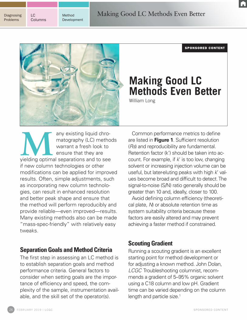
any existing liquid chro-matography (LC) methods warrant a fresh look to ensure that they are
yielding optimal separations and to see if new column technologies or other modifications can be applied for improved results. Often, simple adjustments, such as incorporating new column technolo-gies, can result in enhanced resolution and better peak shape and ensure that the method will perform reproducibly and provide reliable—even improved—results. Many existing methods also can be made “mass-spec-friendly” with relatively easy tweaks.
Separation Goals and Method CriteriaThe first step in assessing an LC method is to establish separation goals and method performance criteria. General factors to consider when setting goals are the impor-tance of efficiency and speed, the com-plexity of the sample, instrumentation avail-able, and the skill set of the operator(s).
Common performance metrics to define are listed in Figure 1. Sufficient resolution (Rs) and reproducibility are fundamental. Retention factor (k’) should be taken into ac-count. For example, if k' is too low, changing solvent or increasing injection volume can be useful, but later-eluting peaks with high k’ val-ues become broad and difficult to detect. The signal-to-noise (S/N) ratio generally should be greater than 10 and, ideally, closer to 100.
Avoid defining column efficiency (theoreti-cal plate, N) or absolute retention time as system suitability criteria because these factors are easily altered and may prevent achieving a faster method if constrained.
Scouting GradientRunning a scouting gradient is an excellent starting point for method development or for adjusting a known method. John Dolan, LCGC Troubleshooting columnist, recom-mends a gradient of 5–95% organic solvent using a C18 column and low pH. Gradient time can be varied depending on the column length and particle size.1
M
Making Good LC Methods Even BetterWilliam Long
Making Good LC Methods Even Better
27 FEBRUARY 2019 | LCGC SPONSORED CONTENT
Diagnosing Problems
Method Development
LC Columns
The gradient scouting run will help deter-mine whether an isocratic or a gradient method is preferable. If the peaks are spread out over the gradient range, a gradient method is indicated. If peaks are clustered and elute in a narrow organic range, an isocratic method will likely be sufficient. Running a fast gradient, such as a 15-min gradient on a shorter, effi-cient column, may indicate that additional method time is either needed or wasted.
Column and Buffer ScreeningColumn and buffer screening can be carried out by running scouting experi-ments using various short, fast columns in combination with different mobile
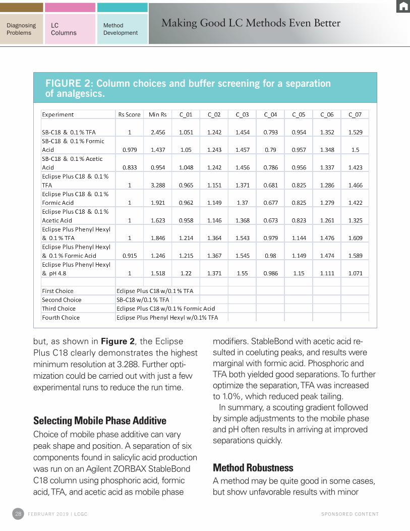
phase buffers. An experiment was carried out separating a group of nonsteroidal anti-inflammatory drugs using sub-2-μm rapid-resolution high-throughput columns (Agilent ZORBAX StableBond [SB-C18, Eclipse Plus C18, Bonus-RP, and the Eclipse Plus Phenyl-Hexyl) with three typ-ical low-pH buffers (0.1% trifluoroacetic acid [TFA], 0.1% formic acid, and 0.1% acetic acid), ammonium acetate as a mid-level buffer, and water for column rinsing. Scouting gradients were used starting at 4% MeCN for the SB-C18, 8% MeCN for the Eclipse Plus C18, and 0% MeCN for the Bonus-RP and Eclipse Plus Phenyl-Hexyl for a total of 20 combinations.
Nine of the 20 experiments resulted in baseline resolution of all compounds,
FIGURE 1: Common separation goals and performance criteria.
Making Good LC Methods Even Better
28 FEBRUARY 2019 | LCGC SPONSORED CONTENT
Diagnosing Problems
Method Development
LC Columns
but, as shown in Figure 2, the Eclipse Plus C18 clearly demonstrates the highest minimum resolution at 3.288. Further opti-mization could be carried out with just a few experimental runs to reduce the run time.
Selecting Mobile Phase AdditiveChoice of mobile phase additive can vary peak shape and position. A separation of six components found in salicylic acid production was run on an Agilent ZORBAX StableBond C18 column using phosphoric acid, formic acid, TFA, and acetic acid as mobile phase
modifiers. StableBond with acetic acid re-sulted in coeluting peaks, and results were marginal with formic acid. Phosphoric and TFA both yielded good separations. To further optimize the separation, TFA was increased to 1.0%, which reduced peak tailing.
In summary, a scouting gradient followed by simple adjustments to the mobile phase and pH often results in arriving at improved separations quickly.
Method RobustnessA method may be quite good in some cases, but show unfavorable results with minor
FIGURE 2: Column choices and buffer screening for a separation of analgesics.
Making Good LC Methods Even Better

29 FEBRUARY 2019 | LCGC SPONSORED CONTENT
Diagnosing Problems
Method Development
LC Columns
changes in conditions. Ideally, a minimum resolution of 2.0 should be maintained for the method to ensure complete separation of peaks. Often, small tweaks can boost mini-mum resolution and, thus, improve method robustness.
A separation of alkyl phenones was run on an InfinityLab Poroshell EC 4.6 mm x 50 mm, 2-μm C18 column at flow rates from 1.0 mL/min to 2.0 mL/min. Pressure increased, as expected, from 99 bar to 204 bar, but a rea-sonable resolution of 2.05 was maintained throughout the runs.
The separation was carried out on three different columns to test method robust-ness. While one column yielded a resolution
of 2.05 for the separation, the other two columns showed somewhat lower resolu-tion: 2.03 and 1.99. One objective was to ensure that the method would perform with a minimum resolution of 2.0, so slightly more water was added to the mobile phase and acetonitrile was reduced from 65% to 60%. With this slight adjustment, resolution in-creased to 2.55, 2.54, and 2.56 for the three columns, ensuring a robust method.
Taking Advantage of New Column TechnologyTesting newer technologies, such as new columns, is another productive avenue for
FIGURE 3: Nortriptyline and dipropyl thalate run on the Eclipse Plus and a C18 column from an existing method.
Making Good LC Methods Even Better

30 FEBRUARY 2019 | LCGC SPONSORED CONTENT
Diagnosing Problems
Method Development
LC Columns
improving methods. For example, Agilent has developed new surface treatments for C18 columns to reduce peak tailing and also to improve their stability with high pH without changing selectivity. The develop-ment of superficially porous columns, such as the InfinityLab Poroshell 120 EC-C18 and Eclipse Plus, also yields the advantages of lower pressure, higher performance, and less sample preparation.
Figure 3 illustrates a simple preparation of a customer’s sample of nortriptyline and dipropyl thalate run on the Eclipse Plus and another C18 column using their method and a 25 mmol, pH 7.4 phosphate buffer. The improved bonded phase of the Eclipse Plus
resulted in better sensitivity, sharp peaks, better resolution, and a flatter baseline.
Agilent has developed an InfinityLab Poroshell column called “HPH” (high pH stability). This column takes advantage of using changes in pH to control selectivity in a separation. An offshoot of this column is the InfinityLab Poroshell HPH C18 column, which lasts longer in phosphate buffer than previous columns and maintains excellent performance. Even methods involving com-plex samples can be switched to this column with minimal adjustments while maintaining similar selectivity and with the added benefit of excellent lifetime at mid-pH ranges.
Rotor seal considerations. When operating
FIGURE 4: Separation of sulfa drugs scaled from a 5-μm Zorbax to a 2.7-μm InfinityLab Poroshell 120 column.
Making Good LC Methods Even Better

31 FEBRUARY 2019 | LCGC SPONSORED CONTENT
Diagnosing Problems
Method Development
LC Columns
using high-pH mobile phases, some parts of the instrument may break down. The rotor seals found in injector valves and on some other valves are made of a polyimide material (Vespel) and are susceptible to attack at pH levels greater than 10 by compounds such as ammonium hydroxide or ammonium carbon-ate. PEEK rotor seals can be used in place of Vespel if high-pH mobile phases will be used for extended periods.
Improvements Using Superficially Porous columnsSimply changing from a totally porous col-umn to a superficially porous column, such as InfinityLab Poroshell 120, is another
option for method improvement. Figure 4 shows a separation of sulfa drugs scaled from a 5-μm Agilent ZORBAX Eclipse Plus column to a 2.7-μm InfinityLab Poroshell 120 column. All 10 peaks elute in about 7 min on the InfinityLab Poroshell, which is before the first peak elutes on the longer column. Sensitivity is improved, and, even though less material is injected, the S/N ratio is higher, resulting in sharper, com-pressed peaks, which are ideal for further optimization. No change in sample prepara-tion was required, and both separations can be run at pressures less than 400 bar.
Many compendial methods, such as those in the U.S. Pharmacopeia (USP), can poten-tially be upgraded. The USP provides guide-lines on allowable adjustments (Figure 5). For
FIGURE 5: Allowable method adjustments for isocratic and gradient sepa-rations according to the US Pharmacopeia.
Making Good LC Methods Even Better

32 FEBRUARY 2019 | LCGC SPONSORED CONTENT
Diagnosing Problems
Method Development
LC Columns
isocratic methods, if the column length (L) to particle diameter (dp) ratio is kept to within –25% to +50% of the original or if the num-ber of plates (N) is within that ratio, no revali-dation is needed. This flexibility in method adjustment is allowed as long as linear veloc-ity is kept constant. Injection volume also can be changed to meet detection limits.
Very few changes are allowed for gradient methods without revalidation; however, the USP currently is investigating possible allow-able adjustments.
Simple Scaling of MethodsThe USP method for naproxen was scaled up from a 5-μm totally porous material (Agilent ZORBAX Eclipse Plus) to a 2.7-μm superfi-cially porous material (Agilent InfinityLab Po-roshell 120). Values for the standard method were N = 10,639, Rs = 13.7, and an L/dp ratio of 30,000. Changing the method to a 4.6 mm x 100 mm column resulted in almost a 100% improvement in N, but the L/dp ratio only 23%, which meets the USP requirements for an allowable method adjustment. A shorter column (4.6 mm x 50 mm) column was tried, which increased N from 10,639 to 11,281 and maintained similar resolution as described by the method (Rs > 11.5).
Poroshell particles are scalable across the family. Agilent recommends specific column pore sizes for different types of applica-tions. For a simple improve-ment in HPLC performance, a 4-μm column might be sufficient and typically yields about a 200% improvement in performance over a 5-μm
totally porous column. The 2.7-μm column is a workhorse that provides UHPLC per-formance at substantially lower pressures. These columns are now available in 1000 bar and show typical pressures that are about 50% of a sub-2-μm totally porous particle column and provide about 90% of the effi-ciency with no additional sample preparation needed. The 1.9-μm column gives extremely high UHPLC performance and pressures similar to those of sub-2-μm totally porous particle columns and 120% of the efficiency.
Converting LC Methods to LC–MSMass spectrometry (MS) is widely used for the analysis of polar to very nonpolar com-pounds. Electrospray ionization (ESI) can be used in MS for both high and lower molecu-lar weight compounds and is, thus, suitable for diverse samples. ESI should be avoided with more nonpolar samples because charge induction will be inefficient and not much signal will be produced. Atmospheric pres-sure photoionization (APPI) or atmospheric chemical ionization (APCI) can be used for these compounds.
ESI is used widely In many cases, iden-tifying unknown compounds is a goal of method improvement. And, because LC–MS equipment has become easier to use and
The LC Handbook: Guide to LC Columns and Method Development
SPONSOR’S CONTENT
Making Good LC Methods Even Better
33 FEBRUARY 2019 | LCGC SPONSORED CONTENT
Diagnosing Problems
Method Development
LC Columns
is more readily available in laboratories, it is desirable to develop methods that are more MS-friendly.
Method considerations for ESI-MS are:• pH of the mobile phase (and analyte pKa)
affects ion formation and, therefore, signal• voltage applied to the electrospray probe
will induce ion formation• choosing the best mobile phase pH can
improve sensitivity• organic solvent has little effect on ionization,
but it affects evaporation, so more volatile mobile phases can be advantageous
• ESI works best at flow rates less than 0.5 mL/min
• ESI is compatible with reversed-phase, hydrophobic interaction, and normal-phase HPLC
Buffer considerations for ESI include:• buffer concentrations below 25 mM are
advisable to avoid signal-dampening effects (best below 10 mM)
• ESI has poor compatibility with non-volatile buffers due to deposit buildup and metal ion buffer interference with ionization
• acidic mobile phases generally favor posi-
tive mode ionizationo 0.1– 1% formic acid, 0.1–1% acetic
acid, 0.05–0.2% TFAo ammonium salts favor formation of am-
monium adductso TFA causes ion suppressiono use a TFA “fix”—postcolumn addition
of acetic or propionic acid• basic mobile phases favor negative mode
ionization
A separation of 10 compounds found in green tea was run using a phosphoric-acid-based mobile phase with acetonitrile (Agilent ZORBAX SB-C18, 4.6 mm x 150 mm column). The separation was accom-plished nicely within about 15 min on a 5-μm column. Phosphoric acid is not MS-friendly, however, and a method goal was to increase the speed of the separation.
By running the separation on an Agilent InfinityLab Poroshell 120 SB-C18 column, which has comparable selectivity, the analy-sis was accomplished at about 60% of the backpressure. The same type of the selectiv-ity could be achieved using 0.2% formic acid, 0.2% acetic acid, 0.02% TFA, or an ammoni-um formate buffer adjusted with formic acid could be used and get similar separations.
The MS sensitivity was significantly affect-ed by these choices. Examining one particular peak as a means of evaluating the separations revealed that using acetic acid gave S/N = 155 versus 68 using TFA, and the buffered mobile phase gave only S/N = 33, so acetic acid was a good choice in this case, and the method
Automated LC Method Development Webinar Series
SPONSOR’S CONTENT
Making Good LC Methods Even Better

34 FEBRUARY 2019 | LCGC SPONSORED CONTENT
Diagnosing Problems
Method Development
LC Columns
FIGURE 6: Transfer of an existing method for antibiotics to MS using a) a methanol mobile phase, b) an acetonitrile mobile phase.
Making Good LC Methods Even Better

35 FEBRUARY 2019 | LCGC SPONSORED CONTENT
Diagnosing Problems
Method Development
LC Columns
could be optimized quickly.Data collection rate should also be con-
sidered in optimization. Fast data collection yields the narrowest peaks, resulting in op-timal peak capacity, but it also means more baseline noise and reduced S/N sensitivity. Optimal S/N is achieved at slightly slower data collection rates, but at the cost of reduced peak capacity. Data collection rate, therefore, should be optimized according to the goals of the particular method.
Developing a new method suitable for MS is another approach. An existing UV method for the separation of antibiotics used to treat animals showed, for example, 10 compounds that were nicely separated. The method, however, used a very high concen-tration of phosphoric acid, and the separa-tion had a run time of 35 min. Because an equivalent column was not available, a new method was developed beginning with run-ning generic gradients of 10% to 40% meth-anol or acetonitrile. The use of a short 4.6 x 50 mm, 2.7-μm InfinityLab Poroshell 120 EC-C18 column and UV detection allowed for rapid screening of different mobile phase combinations with formic acid, ammonium formate, acetic acid, and ammonium acetate as mobile phase buffers.
As shown in the methanol runs in Figure 6a, peaks shifted substantially depending on the type of buffer used. Peak shifting in the acetonitrile runs (Figure 6b) was less and pressure was much lower. pH was adjusted to vary elution order and peak spacing. The best mobile phase combination was found to be pH 3.8 ammonium formate with acetonitrile, which resulted in a good separa-tion of these 10 compounds. Flow rate was
increased to 0.42 mL/min to optimize the method for MS detection.
This method was successfully scaled to a 3 mm x 50 mm column, which can be used for UV or MS detection. The separation is fast and uses much less solvent than the original method.
ConclusionMost laboratories will benefit from review-ing their LC methods to determine if simple adjustments can be made to improve chro-matographic results or to make methods MS-friendly. Column choice is a significant factor in successful analyses, and newer column chemistries often can be applied for improved resolution and better peak shape through taking advantage of alternative selec-tivities.
Reference1. J. Dolan, LCGC 31(1), 30-35 (2013).
William Long
LC Columns Applications ScientistAgilent Technologies
Making Good LC Methods Even Better

Increase Productivity While Meeting Data Integrity RequirementsUpgrade to Agilent OpenLab CDS
Choosing the right data system can make all the difference. OpenLab CDS is a single, secure chromatography data system for chromatography and single-quadrupole MS workflows that enables you to streamline laboratory operations and efficiently generate quality results.
OpenLab CDS ensures data integrity and facilitates rigorous regulatory compliance with your choice of technical controls—such as audit trail review, access control, records protection, and e-signatures.
Learn more about Agilent OpenLab CDS.
© Agilent Technologies, Inc. 2018
www.agilent.com/chem/ openlabcds-streamline


![[PPT]Liquid Chromatography Fundamentals - Theory · Web viewLiquid Chromatography Fundamentals - Theory Keywords HPLC, LC, HPLC theory, HPLC fundamentals, teaching HPLC, learning](https://img.dokumen.tips/doc/110x75/5b1aa2c67f8b9a3c258de481/pptliquid-chromatography-fundamentals-theory-web-viewliquid-chromatography.jpg)