Embed Size (px)
Citation preview
Best Practice in Robotics (BRICS)
Grant Agreement number: 231940
01.03.2009 – 28.02.2013
Instrument: Collaborative Project (IP)
Design principles, implementation guidelines, evaluation criteria for
system openness and flexibility and use case implementations
Davide Brugali, Patrizia Scandurra, Angelo Gargantini, Luca Gherardi, Andrea Luzzana, Marco Pedroni
Deliverable D7.1
Lead contractor for this deliverable: Università degli Studi di Bergamo
Due date of deliverable: September 01, 2010
Actual submission date: September 01, 2010
Dissemination level: Public
Revision: 1.0

2
BRICS Deliverable D7.1
Executive summary
This deliverable documents the work performed by the authors in the context of work package WP7 of the EU project BRICS. The authors of this report all work at the University of Bergamo, which is the partner in BRICS responsible for promoting and supporting the development of Open and Flexible Robotic Systems.
WP7 is a cross-sectional work package as Openness and Flexibility are requirements that need to be addressed in every phase of the robotic system development process. Openness and Flexibility are quality factors of the entire robotic system as well as of each of its constituent parts.
More specifically, this deliverable covers partially Task 7.1 ―Best Practice in system Openness and flexibility‖, Task 7.2 ―Metrics to evaluate system openness and flexibility‖, and partially Task 7.4 ―Design Principles for system openness and flexibility‖
This deliverable is structured in four main sections: the rest of Section 1 introduces the role of work package WP7 in the BRICS project. Section 2 illustrates background concepts. Section 3 analyses criteria for evaluating software flexibility. Section 4 presents design principles and implementation guidelines.
3
BRICS Deliverable D7.1
Contents
1. Introduction ....................................................................................................... 5
1.1. The BRICS Approach .................................................................................... 6
2. Concepts and Background................................................................................ 8
2.1. Reusability of Robot Software Systems ......................................................... 8
2.2. Key properties of reusable software components ........................................ 11
2.3. System Openness ....................................................................................... 12
2.4. System Flexibility ......................................................................................... 13
2.4.1. Flexibility in decision theory .................................................................. 13
2.4.2. Flexibility in manufacturing systems ...................................................... 13
2.4.3. Flexibility in engineering design ............................................................ 14
2.4.4. Flexibility in Software Engineering ........................................................ 14
2.5. Software maintenance and refactoring ........................................................ 15
3. Evaluation criteria ........................................................................................... 19
3.1. Evaluation models ....................................................................................... 19
3.1.1. Syntactic versus semantic analysis ....................................................... 20
3.1.2. Engineering models versus software quality models ............................ 20
3.2. Best Practice in Domain Analysis ................................................................ 21
3.3. Variability in the Robotics Domain ............................................................... 21
3.3.1. Functional variability ............................................................................. 22
3.3.2. Hardware variability .............................................................................. 22
3.3.3. Application variability ............................................................................ 23
4. Design Principles and Implementation Guidelines .......................................... 24
4.1. Best Practice in software development and reuse techniques .................... 24
4.1.1. Object Oriented Programming (OOP) ................................................... 25
4.1.2. Design patterns ..................................................................................... 25
4.1.3. Architectural styles ................................................................................ 25
4.1.4. Application frameworks ......................................................................... 26
4.1.5. Component-based software engineering (CBSE) ................................. 26
4.1.6. Model-driven Engineering (MDE) .......................................................... 27
4.1.7. Software Product Lines ......................................................................... 28
4.1.8. Models@Runtime ................................................................................. 28
4.2. The BRICS Component Framework for Robotics ........................................ 29
4.2.1. Refactoring towards component frameworks ........................................ 29
4.2.2. Refactoring of non-functional aspects ................................................... 31
4
BRICS Deliverable D7.1
4.3. Implementing variability in the BRICS Component Framework ................... 32
4.3.1. Inheritance and Extension..................................................................... 32
4.3.2. Aggregation and Delegation.................................................................. 32
4.3.3. Parameterization ................................................................................... 33
4.3.4. Conditional Compilation ........................................................................ 33
4.3.5. Dynamic-Link Libraries ......................................................................... 33
4.4. Managing variability in the BRICS Component Framework ......................... 34
4.5. Separation of Concerns in component-based systems ............................... 36
4.6. Component configuration ............................................................................ 38
4.6.1. Intra-assembly configuration ................................................................. 39
4.6.2. Inter-assemly configuration ................................................................... 40
4.7. Component communication ......................................................................... 41
4.7.1. Component Decoupling ........................................................................ 41
4.7.2. Remothe Method Invocation ................................................................. 43
4.7.3. Publish/Subscribe ................................................................................. 43
4.8. Component coordination ............................................................................. 44
4.8.1. Coordination Models and Languages ................................................... 45
4.8.2. Connectors as Coordination Components ............................................ 46
5. Conclusions .................................................................................................... 47
6. References ..................................................................................................... 48

BRICS Best Practice in Robotics
5
BRICS Deliverable D7.1
1. Introduction Software is an integral part of robotic systems. The availability of faster processors with larger memories and lower power consumption makes it technically and economically feasible to embed computing capabilities within individual robotic devices, which may range from servo-motor controllers, to smart sensors such as 3D vision systems, up to mobility platforms and manipulator arms. Progress in network and communication technologies allows to build distributed embedded systems onboard individual robots or across multi-robot systems. High-level programming languages and advanced software tools simplify the development and deployment of concurrent and real-time applications, which implement the wide spectrum of robot functionality, such as sensing, planning, control, reasoning, and learning. Code generators and compilers help software developers to optimize their code when computational performance is a major requirement, especially for autonomous robots, which process large volumes of sensory information and have to react in a timely fashion to events occurring in the robot operational environment.
One of the key attributes of a mature engineering discipline is the routine use of existing solutions in the development of new systems. As robotics systems are becoming more complex, distributed, and integrated, there is the need to promote the construction of new systems as composition of reusable building blocks. System openness and flexibility are key factors that enable the development of reusable software. If a system is flexible, its functionality can be customized by replacing individual components. If a system is open, individual research groups can contribute to its evolution by providing leading edge research solutions.
State-of-the-practice in robotic software reuse is still at an infant stage. This may be due to cultural factors (robotics has traditionally been the realm of experts in mechanics, electronics, automatic control, computer vision, and artificial intelligence), to contingent factors (so far there has been no sustained push to design reusable and interoperable software), but to technological and scientific challenges as well.
Complexity. Software for advanced robotics systems is typically embedded, concurrent, real-time, distributed, and data intensive. In addition, robotics software must exhibit specific system properties, such as safety, reliability, and fault tolerance. Developing modular and reusable software components, systems, and applications demands for advanced technical skills both in software and system engineering. Advanced concepts such as software flexibility, portability, scalability, and interoperability must be adequately mastered.
Variability. Robot systems are highly change-centric systems. Robotics is an experimental science that can be analyzed from a double perspective. On one hand, it is a discipline that has its roots in mechanics, electronics, computer science and the cognitive sciences. In this regard, software plays the role of integrator, implementing and bringing together advanced research results in order to build complex robotic systems. On the other hand, Robotics is a research field that pursues ambitious goals, such as the study of intelligent behaviour in artificial systems. As a consequence, reusable robotic software artefacts need to be flexible enough to capture quickly-changing technological and functional requirements. More specifically, robot hardware variability, environmental variability, and task variability are major barriers to software reuse. Addressing this challenge demands for a deep knowledge and understanding of the application domain, both in terms of core
BRICS Best Practice in Robotics
6
BRICS Deliverable D7.1
aspects (entities, functionality, properties) of the domain that are unlikely to change, since they are part of the essence of the domain, and in terms of technological and functional requirements evolution trends.
Despite the severe challenges that researchers and developers have to face in order to introduce software reuse practice in robotic system development, robotic software reuse is both technologically feasible and economically advantageous. More strongly, software reuse is mandatory in order to make robot software development sustainable in a fast evolving market, where recent advances in robotics and mechatronics technologies have stimulated expectations for emergence of a new generation of robotic devices that interact and cooperate with people in ordinary human environments.
1.1. The BRICS Approach
Robot software developers often feel a sense of frustration when they develop an application from scratch that is (nearly) the same as several other releases for different projects because thay have not been able to capture and exploit the commonalities.
Most of the best practice software libraries for robotics are based on software architectures invented from scratch each time. Many valuable robotic applications are monolithic systems that have been developed to solve a specific class of problems. Usually, reuse is considered only at the implementation stage. This practice limits reuse to fine-grain modules at best and fails to allow for broader utilization of assets at a subsystem or higher level since planning at earlier stages of development is neglected.
As a consequence, a large corpus of software that implements the best practice robotics algorithms and provide the most common robot functionality is now available within the research labs worldwide, but it is not easily reusable to build new robotics applications.
In this scenario the BRICS project applies a novel approach, which avoids to develop from scratch robot functionality based on yet another software architecture, middleware, and information model. The main objective of BRICS is to collect, analyse, and refactor software that implements best practice algorithms and architectures in Robotics and to make it available as reusable components.
In order to pursue this objective, BRICS components need to be be open and flexible because today‘s best practice in robotics, which will not be considered best practice anymore after the end of the project. BRICS components are likely to survive after the end of the project only if they will be easily maintainable. In fact, System obsolescence and retirement can therefore be attributed to the inability of said systems to meet changing mission requirements resulting from changing environments [Mark, 2005]. If flexibility is the ability of a system to be easily modified to accommodate requirement changes, then flexibility can be conceived of as the system characteristic by which the slip into obsolescence is postponed [Saleha et al., 2008].
The work performed in work package WP7 ―Openness and Flexibility‖ supports the BRICS overall approach by establishing an iterative collaboration process with the other work packages in the project as depicted in Figure 1.

BRICS Best Practice in Robotics
7
BRICS Deliverable D7.1
Figure 1:The BRICS iterative refactoring process towards reusable components
At any stage of the project, best practice open source libraries are collected, analysed, and selected in work packages WP2 and WP3.
Selected open source libraries are evaluated to assess their degree of openness and flexibility (Task T7.2)
Adequate development methods and techniques are identified from the best practice in Software Engineering and from the analysis of the application domain (Task T7.1) in order to support the refactoring of the selected open source libraries.
A set of design principles and implementation guidelines are delivered (Task T7.4) to make design improvements and to reengineer the implementation of the selected open source libraries.
As a by-product of the refactoring process, a set of UML models are developed, which represent recurrent and stable data structures and architectures (T7.3).
BRICS Best Practice in Robotics
8
BRICS Deliverable D7.1
2. Concepts and Background
2.1. Reusability of Robot Software Systems
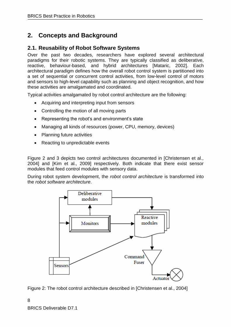
Over the past two decades, researchers have explored several architectural paradigms for their robotic systems. They are typically classified as deliberative, reactive, behaviour-based, and hybrid architectures [Mataric, 2002]. Each architectural paradigm defines how the overall robot control system is partitioned into a set of sequential or concurrent control activities, from low-level control of motors and sensors to high-level capability such as planning and object recognition, and how these activities are amalgamated and coordinated.
Typical activities amalgamated by robot control architecture are the following:
Acquiring and interpreting input from sensors
Controlling the motion of all moving parts
Representing the robot‘s and environment‘s state
Managing all kinds of resources (power, CPU, memory, devices)
Planning future activities
Reacting to unpredictable events
Figure 2 and 3 depicts two control architectures documented in [Christensen et al., 2004] and [Kim et al., 2009] respectively. Both indicate that there exist sensor modules that feed control modules with sensory data.
During robot system development, the robot control architecture is transformed into the robot software architecture.
Figure 2: The robot control architecture described in [Christensen et al., 2004]

BRICS Best Practice in Robotics
9
BRICS Deliverable D7.1
Figure 3: The robot control architecture described in [Kim et al., 2009]
Within software engineering, software architecture is typically defined as the structure or structures of the system which comprises software components, the externally visible properties of those components, and the relationships among them [Bass, 1999]. Here, components are units of implementation and represent a code-based way of considering the system. Thus, the robot software architecture describes the decomposition of the robot control system into a collection of software components, the encapsulation of functionality and control activities into components, and the flow of data and control information among components. The design or selection of the software architecture specifically takes into account non-functional requirements of a robotic software system (maintainability, portability, interoperability, scalability), that is, those requirements that characterize software quality and enable software reuse.
As an example, Figure 4 and Figure 5 depict the software architectures corresponding to the control architectures depicted in Figure 2 and Figure 3 respectively. Both define the organization of the software system as a set of interconnected components that implement specific algorithms, such as those for task planning, navigation, locomotion, pose estimation, etc.
The mapping of robot tasks to components, that is how algorithms, data structures, synchronization, and communication mechanisms are packaged together and the definition of component interactions are crucial design steps, as they greatly influence the reusability of those components. For example, it should be noted that in Figure 4 the sensor component pushes data into the ―Detecting‖ component, while in Figure 5 the ―Navigation‖ component reads data from the sensor component. Thus, while both control architectures indicate that the sensor modules provide the control modules with sensory data, the two software architectures differ for the interaction patterns (push/pull) between the sensor component and the control components.
As a consequence, the sensor component is not reusable across the two applications. The problem originates from the fact that the two sensor components mix two different aspects: the component functionality (i.e. providing sensory data) and the interaction pattern (push/pull). While the former is a stable property of the sensor component and thus should be reusable, the latter is a variable requirement of the application and thus should be flexible.

BRICS Best Practice in Robotics
10
BRICS Deliverable D7.1
Figure 4: Te robot software architecture described in [Christensen et al., 2004]
Figure 5: The robot software architecture described in [Kim et al., 2009]

BRICS Best Practice in Robotics
11
BRICS Deliverable D7.1
2.2. Key properties of reusable software components
Ideally, components embedding common robot functionality should be reusable in different robot control systems and application scenarios, and thus they should not be bounded to specific robotic hardware, software-development technologies, or control paradigms. For example, a fully reusable component implementing a mobile robot navigation algorithm should be designed without implicit assumptions about the computational environment (e.g., stand-alone application or distributed system), the possible use (e.g., map building or object tracking), and the robot mechanics (e.g., size and shape).
In reality, designing reusable components consists in finding the best tradeoff between being too specific (less reusable) and too generic (less valuable). Three aspects of a reusable component are equally important: quality, technical reusability, and functional reusability.
The quality of a robotic software component is typically expressed in terms of its computational performance (e.g., the time required to process a video frame), efficiency (e.g., the amount of memory used to build a probabilistic road map), or reliability (e.g., the probability of returning a sensor measure when needed). Quality can be assessed here and now, provided that adequate metrics and benchmarks are available (e.g., a standard reference image for testing different edge detection algorithms or different implementations of the same algorithm).
From a functional point of view, reusable components can be classified with respect to application domains into two broad categories (see Figure 6): horizontal and vertical components.
Figure 6: Vertical and horizontal components
The term domain is used to denote or group a set of systems (e.g., mobile robots, humanoid robots) or applications (service robotics, space robotics, etc.) that exhibit similar characteristics or fulfil similar requirements. Horizontal components provide functionality to a variety of applications that may implement totally different use cases.

BRICS Best Practice in Robotics
12
BRICS Deliverable D7.1
Typical horizontal components provide system services such as interfacing to hardware devices, providing computational or communication services, or implementing mathematic functions. Vertical components capture a company, organization, or research community know-how in specific functional areas such as kinematics, motion planning, deliberative control, and address the requirements of target application domains such as service robotics, space robotics, or humanoid robotics. It has been reported [Poulin, 1996] that vertical components contribute the most to reuse, up to 65% of any application, while horizontal components typically contribute no more than 20%. Functional reusability requires insight into the future and a clear understanding of how robotic systems integrating reusable components will likely evolve. The three reusability aspects described earlier are equally important [Ezran, 1998]. The highest-quality component will never be reused if the function it offers is useless. The most-needed component will never be reused if it is unreliable, slow, and hard to understand. The highest-quality and most-needed component will never be reused if the interface is not compatible.
Technical reusability of a robotic software component is mainly concerned with its degree of openness and flexibility. We discuss these aspect in the following two sections.
2.3. System Openness
The concept of openness applies to any kind of design artefacts, whether they are software (e.g. source code, APIs, architectures, algorithms, protocols), hardware (mechanical components, electronic devices), or any combination of them created to form the systems.
A design artefact is open if its specifications are made public by the designers. The main advantage of being open is that anyone can design add-on artefacts for it. The main disadvantage is the difficulty in preserving the designer‘s intellectual property. When this is a concern, the artefact specifications are kept private and are said to be closed or are protected by trademark, patent, or copyright and are said to be proprietary. Thus, an artefact specifications may be public but not for free and their commercial exploitation regulated by licensing.
One interesting aspect related to an artefact‘s openness is the degree of usability of its specification. An artefact specification could be public and even free but not usable at all. For example, the source code of a software library is not usable if it is not properly documented; an open hardware component or software library is not usable if the cost of its exploitation (e.g. integration with the rest of the system) is too high. In some cases, it is more convenient to design and build the artefact from scratch. Thus, an artefact is considered open not only if its specification is public but also if it has well-defined interfaces that promote interoperability with third-party artefacts, and is portable to multivendor equipments. The most notable example of an open software artefact is the ISO-OSI reference model.
According to the IEEE Standards Computer Dictionary, interoperability is the "ability of two or more systems or components to exchange information and to use the information that has been exchanged." Interoperability with third-party systems can be achieved by designing well-defined component interfaces, protocols, and data-exchange formats, clearly separating component interface and implementation, and conforming the component‘s specification to existing standards.

BRICS Best Practice in Robotics
13
BRICS Deliverable D7.1
Portability is defined as the ability of a given software artefact to run on more than one computer platform and operating environments. By extension, portability refers to the idea of hardware independence of a software artefact. Portability can be achieved by making the software dependencies to the hardware platform explicit. This requires defining abstract models of hardware platforms and developing software artefacts against these models.
2.4. System Flexibility
Flexibility is a concept that has different meaning in different disciplines. In [Saleh et al., 2008] the authors have reviewed the concept of flexibility as discussed in a number of academic disciplines. In the following we summarize the main concepts identified in [Saleh et al. 2008], which are relevant for the work described in this report.
Intrinsic to the notion of flexibility is the ability or potential to change and adapt to a range of states. The common ground on which all disciplines agree is that flexibility is needed in order to cope with uncertainty and change, and that it implies an ease of modification and an absence of irreversible or rigid commitments. Flexibility is more about a potential to change, and thus, unlike system performance, it is difficult to observe and measure. [Saleh et al. 2008].
2.4.1. Flexibility in decision theory
Mandelbaum and Buzacott [Mandelbaum et al., 1990] develop a framework for flexibility in the context of decision theory. They consider a two-period decision problem in which A and B are sets of decision choices in the first and second period, respectively. Once a decision a is made in the first period, a ∈ A, the remaining choices available in the second period become constrained to a subset of B, B(a) ⊆ B. The definition and measure of flexibility that Mandelbaum and Buzacott [Mandelbaum et al., 1990] put forward is the number of options still open in the second period after a decision has been made in the first period. In other words, flexibility is the number of remaining alternatives after a first commitment is made: more remaining choices reflect increased flexibility.
Robot system development is a multi-phase decision problem. At each phase, specific technologies must be selected, which may lock-in the subsequent development phases. For example, the selection of a middleware infrastructure may limit the reusability of third-party open source libraries implementing useful functionality.
2.4.2. Flexibility in manufacturing systems
Manufacturing is another area that is strongly associated with issues of flexibility. Research on flexibility in manufacturing systems has grown dramatically over the past 30 years. Flexibility in this area is generally accepted to be an attribute of a manufacturing system that is capable of changing in order to deal with uncertainty and a changing environment [Sethi and Sethi, 1990]. Flexibility thus implies an ability to reconfigure manufacturing resources in order to continue producing efficiently different products in response to, or to preempt, changes in the system‘s environment [Sethi and Sethi, 1990].
BRICS Best Practice in Robotics
14
BRICS Deliverable D7.1
A robotic system is typically composed of a large selection of hardware (e.g sensors and actuators), software (e.g. algorithms), and computational resources. In this context, flexibility means the ease with which he resources can be composed and the overall system reconfigured at runtime to enhance robot robustness and autonomy.
2.4.3. Flexibility in engineering design
In [Saleh et al. 2003] flexibility is defined as ‗a property of a system that allows it to respond to changes in its initial objectives and requirements – both in terms of capabilities or attributes – occurring after the system has been fielded, in a timely and cost-effective way‘. A corollary of this definition is that a flexible system can be easily modified to satisfy different requirements at different points in time.
Platform design and modularity are traditionally associated with flexibility. The general thought is that a product platform ‗can be easily modified through the addition, substitution, and exclusion, of modules to realize a module-based product family‘ [Simpson et al. 2001], thus providing flexibility to the product or the product family. A product platform is defined as ‗the set of common parameters, features, and/or components that remain constant from product to product, within a given product family‘ [Simpson et al. 2001], and a product family is defined as a ‗group of related products that is derived from a product platform to satisfy a variety of market niches‘ [Simpson 2003]
In summary, the notion of design flexibility can be understood as the inverse of a system‘s impedance to change – to take an analogy from electrical engineering. Flexibility in design (or a flexible system) implies that the system has been designed with certain characteristics; for example, additional design parameters, design margins, a particular architecture (platform/modular, or other). These characteristics may not be necessary or justified in the context of optimising the system for the immediate mission (or set of requirements) for which it is being fielded [Mark, 2005].
2.4.4. Flexibility in Software Engineering
The IEEE Standard Glossary of Software Engineering Terminology defines flexibility as the ―ease with which a system or component can be modified for use in applications or environments other than those for which it was specifically designed‖.
The term environment refers to the complete range of elements in an installation that interact with the component-based software system. This includes the computer and network platform, the controlled robotic hardware, and the robotic applications that integrate the reusable components. More specifically, flexibility is concerned with the portability of the component system on different computational environments (e.g., from a centralized to a distributed system), the interoperability among independently developed components (e.g., components interfacing heterogeneous robotic devices), the reusability of individual components in different application contexts (e.g., a motion planner for static or dynamic environments), and the component system reconfigurability at run time (e.g., adaptable robot behaviours).
More specifically, flexibility of software artefacts depends upon the type of the artefact, the development environment, and the evolution of the artefact‘s requirements.
Flexibility is related to the type of software artefact in the sense that properties belonging to the source code, the architecture and the technology used can improve
BRICS Best Practice in Robotics
15
BRICS Deliverable D7.1
or degrade it. The source code and architecture of the program should be comprehensible and they should make possible to implement changes with easiness.
The development environment also affects flexibility. One of the most effective ways of dealing with changing requirements is to adopt an agile process for the development of new software. The team should share knowledge regarding the product that must be maintained so that it will be easier to understand which parts of the program should be modified. Lastly the experience of individuals and the quality of every person in the team, as well as the quality of the team as a whole, play a central role in reducing the mean time to implement a change request in the program.
Finally, flexibility depends upon the type of change request. In case that it is possible to foresee change requests that are likely to be implemented in the future, it would be much easier to develop the program with an architecture that might support those changes.
2.5. Software maintenance and refactoring
Nowadays it is known that maintenance represents an important percentage of the cost for the development of a software artefact [Mangili, 2009]. There are many researches which have made an evaluation of the cost of maintenance in the lifecycle of a program, and those surveys stated that maintenance costs range between 60% and 80% of the total cost of a product.
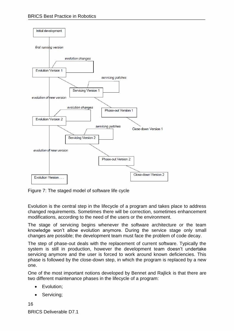
Bennet and Rajlick have proposed a new model for representing the software lifecycle: the staged model [Bennet et al., 2000] (see Figure 7).
This model is composed of the following stages:
1. Initial development;
2. Evolution;
3. Servicing;
4. Phase-out;
5. Close-down.
The initial development step aims at creating the first version of the program. The software might lack some features, but this phase will define the architecture that will persist through the life of the product.
It is remarkable that the development team will acquire knowledge by realizing the first version; in fact this knowledge is a prerequisite for the subsequent step of evolution.
BRICS Best Practice in Robotics
16
BRICS Deliverable D7.1
Figure 7: The staged model of software life cycle
Evolution is the central step in the lifecycle of a program and takes place to address changed requirements. Sometimes there will be correction, sometimes enhancement modifications, according to the need of the users or the environment.
The stage of servicing begins whenever the software architecture or the team knowledge won‘t allow evolution anymore. During the service stage only small changes are possible; the development team must face the problem of code decay.
The step of phase-out deals with the replacement of current software. Typically the system is still in production, however the development team doesn‘t undertake servicing anymore and the user is forced to work around known deficiencies. This phase is followed by the close-down step, in which the program is replaced by a new one.
One of the most important notions developed by Bennet and Rajlick is that there are two different maintenance phases in the lifecycle of a program:
Evolution;
Servicing;

BRICS Best Practice in Robotics
17
BRICS Deliverable D7.1
We expect that in the servicing phase only corrective maintenance is carried out while in evolution phase, any kind of the maintenance classes can be used. However both the phases can lasts for a very long period of the lifecycle of an application, thus it is important to deal with the problem of evolution in software.
A special kind of evolution step is refactoring.
Refactoring is the process of changing a software system in such a way that it does not alter the external behaviour of the code yet improves its internal structure [Fowler et al., 2002].
Refactoring occurs at two complementary levels:
1. syntactical refactoring is a behavior preserving transformation that, through the adoption of good design principles (abstraction, information hiding, polymorphism, etc.) aims at making software artifacts modular, reusable, open.
2. semantic refactoring is a domain-driven transformation that, through a careful analysis of the application domain (commonality/variability and stability analysis), enhances software artifacts flexibility, adaptability, and portability.
Refactoring process implies removing of duplicate code, simplification of too complex logic flows and improving of code readability. Typically the process evolves by following little and simple steps during which the code is modified. In order to reduce the probability of introducing new bugs after each step the refactored code is tested.
In the book [Kerievsky, 2004], Joshua Kerievsky explained four motivations why the refactoring process can be useful.
1. Make it easier to add new code. When we need to add a new functionality to our software we can operate in two different ways. The first consists in doing it without considering how this new feature fits with the existing design. The second possibility instead consists in modifying the existing design in order to facilitate the integration of new functionalities. The first choice is good when we have little time. Instead, if we have enough time and (more important) if we think that we will have to introduce new features also in the future, then the second choice is definitely better.
2. Improve the design of existing code. Iterative executions of refactoring process make easier to remove what Fowler calls ―Bad smells‖ and then to improve the code design. Bad smells are certain structures in the code that suggest the possibility of refactoring. In their books Fowler and Kerievsky describe and explain how to remove these smells.
3. Gain a better understanding of code. Sometimes when we analyze code can be very hard to understand how it works. In this case add comments may not be enough for those who will have to modify the code in future. They may still not understand it. The best solution is rewriting the code and commenting it. For example a good practice consists in choosing explicative names for variables and methods. Ideally the name of a method should explain which functionality it realizes. Another good solution instead consists in dividing a long method into shorter methods. About the readability of code Fowler said: "Any fool can write code that a computer can understand. Good programmers write code that humans can understand".
BRICS Best Practice in Robotics
18
BRICS Deliverable D7.1
4. Make coding less annoying. Refactoring not only makes code more readable but also can make it less annoying to work with. In this way is simpler and quickly modify the code. For example, when a class has too many responsibilities, every time that we need to modify the code or integrate new functionalities, we have to deal with this complex class. As result we need more time than necessary in order to complete our work. In this case it is convenient rewriting the code and dividing the complex class into simpler classes. This operation will allow a significant saving in terms of time during future work on the code.
Hence refactoring is a process that brings many advantages not immediately but in a long time. The initial cost in terms of time and effort spent for rewriting the code is balanced by the time gained in future. This gain is due to a code more readable, more reusable and more maintainable.

BRICS Best Practice in Robotics
19
BRICS Deliverable D7.1
3. Evaluation criteria By means of the staged model, Bennet and Rajlick have pointed out the fact that we can‘t develop software notwithstanding the evolution and maintenance of the software application. Considering the importance of this quality attribute, it would be extremely useful to make an evaluation of the flexibility of an application.
Assuring adequate values of non-functional requirements like openness, and in particular flexibility, interoperability, and portability, is based on the issue of defining and quantitatively measuring software properties. This is an open problem in software engineering research.
3.1. Evaluation models
The most common approaches used for software quality evaluation are [Mangili, 2009]:
Metrics-based approaches;
Quality models;
Process models.
The first approach is based on the hypothesis that there are some measurable attributes of a software artefact that are believed to affect the maintenance. Such a kind of evaluation makes often use of ―maintainability indexes‖, which are composed by the weighted aggregation of elementary metrics and which are thought to represent the overall maintainability of the software artefact. The greatest problem of this approach is that it just considers properties of the software artefact, but it doesn‘t take into account properties belonging to the change request and the environment. The second problem of this methodology is that it works only at the syntactical level of analysis, thus it disregards the semantics of the product. Moreover the analysis is carried out at the source code level, therefore it doesn‘t focus on architectural phenomena.
Quality models break a complex attribute into more manageable subcharacteristics. This technique is used to build a multi-level tree-like structure of attributes. By means of making an assessment of the lower-level properties, using a bottom-up approach, it will be possible to make an evaluation of the general quality attribute. Although quality models appear to be a more refined way of making the assessment, we haven‘t found any broadly accepted model for the attribute of flexibility. The main critique to this approach is the unrealistic desire to condense into a single number a complex property like the flexibility.
The last approach is the use of process-models, which are based on the questionable assumption that the quality of the software artefact can be derived from the mere analysis of the development process. We believe that the development process does affect the quality attribute of maintainability, however it isn‘t the unique factor that influences it.
A ―deeper‖ approach is based on the identification of patterns in the software product to be evaluated. Patterns may be interpreted as evidences for values of quality attributes. This approach is used in SEI ―Quality Attribute Design Primitives‖ method [Bass, 2000]. Developing open and flexible software artefacts requires the ability to

BRICS Best Practice in Robotics
20
BRICS Deliverable D7.1
anticipate changes by analysing the evolution of software applications and to design for changes by applying effective and reusable solutions to design problems that occur over and over again in robotic software development (design patterns). The pattern-based approach is also able of guiding the development process in order to satisfy system requirements.
3.1.1. Syntactic versus semantic analysis
Syntactic analysis refers to a kind of analysis that is performed at the source code level of abstraction on object-oriented code. This means that we focus our attention on properties belonging to the source, such as the size, complexity, cohesion, and relationships between elements in the code. We don‘t take into account the meaning of the words and phrases of the programming language Supporting software evolution through a diagnostic approach of maintainability used, but we just consider elementary properties of them.
On the other hand the semantic analysis deals with the meaning of the application. Semantic analysis on the software artefact is much more effective than considering only code-level phenomena and is the only way for the analysis to be useful in a realistic environment [Mangili, 2009].
Although automatic tools can support the assessment process, it is necessary that the evaluation is performed by an expert evaluator. We haven‘t found any tool that supports the semantic analysis, however we found many tools that adopted the syntactic approach on object-oriented code.
In BRICS, we have performed a deep semantic analysis of best practice open source robotics libraries by simultaneously analyzing and comparing several implementations of similar functionality in different libraries.
3.1.2. Engineering models versus software quality models
Consider civil engineering and the simulation of the damages of an earthquake. The system is the building that we want to analyze; the input is the earthquake; the output is the state of the building after the earthquake. In order to make a prediction of the output we need both a model of the building, and a model of the earthquake. There are multiple kinds of models [Salvaneschi, 2008], for instance we may use a single object model for the building, or we may use a set of interconnected objects. Furthermore, in order to predict the behaviour, we need to measure or estimate a certain amount of properties which permit to characterize the system and the input. For example we could measure properties of the building, such as the height, and guess properties of the input, like the Richter magnitude of the earthquake.
The approach used in software engineering deeply differs from the one used in other engineering disciplines. The greatest problem is that there aren‘t models that can be used for representing the software system, as does the civil engineering. In fact there aren‘t laws in software similar to those available in mechanics or thermodynamics. This lack of laws in software engineering is another reason for the fact that evaluating the flexibility of a program is so difficult. Thus, the realization of a predictive model in the context of software engineering requires the adoption of a different approach, that is based on a conceptual analysis of the sources of variability in the application domain in order to predict the requirements of future applications. This approach is known as Domain Analysis.
BRICS Best Practice in Robotics
21
BRICS Deliverable D7.1
3.2. Best Practice in Domain Analysis
Domain Analysis refers to a set of activities aimed at developing reusable models within a domain. The fundamental tenet of Domain Analysis is that substantial reuse of knowledge, experience, and software artefacts can be achieved by performing some sort of commonality/variability analysis to identify those aspects that are common to all applications within the domain, and those aspects that distinguish one application from another [Coplien, 1998].
Recently, the focus of domain analysis has moved from the commonality/variability analysis toward the new concept of stability analysis [Fayad, 2002]. In order to enhance reuse, domain models should focus on those aspects of the domain that will remain stable over time. If the entities in the domain have not changed, and have not changed their relationships to each other, for a long time, we can assume that the relationships between the entities will continue to hold through future changes. Therefore, the logical structure of every concrete software system should match the invariant structure of the domain, in order to ensure a stable core design and, thus, stable software artefacts. Those changes that are introduced to the software project will then be in the periphery, since the core was based on something that has remained and will remain stable. Since whatever changes must be made to the software in the future will be in this ―periphery,‖ it will only be these small external modules that will have to be engineered. And, thus, we avoid the endless circle of reengineering entire software projects for minor changes.
In order to support stability analysis, the concept of an Enduring Business Theme (EBT) was first introduced in [Clien and Girou, 2000]. An EBT is an aspect of a domain that is unlikely to change, since it is part of the essence of the domain. After the appropriate enduring themes of the business are understood and catalogued, a software framework can be constructed that enables the development of business objects (BO) which offer application-specific functionality and support the corresponding EBT. BOs have stable interfaces and relationships among each others but are internally implemented on top of more transient components called Industrial Objects (IO).
The identification of EBTs, BOs, and IOs requires a deep knowledge and understanding of the domain. In [Fayad, 2002] the author sketches some heuristics for guiding their identification. In particular, one of the criteria to recognize EBTs, BOs, and IOs is their tangibility. "If an object in a model represents a concrete entity, then it is most likely an Industrial Object" [Fayad, 2002]. Tangibility is considered one of the driving factors of instability of IOs. The reason is that physical entities, such as a piece of machinery, are highly sensitive to technological evolutions.
In BRICS, we have applied the Stability Analysis method to identifying flexibility requirements for best practice robotics software libraries.
3.3. Variability in the Robotics Domain
The intrinsic change-centric nature of robotic applications poses the challenge of designing software components and systems that are flexible enough to accommodate frequently changing functional and non-functional requirements.
The key to achieving software flexibility is the possibility to predict the class of changes that are likely to occur in the environment over the lifespan of robotic

BRICS Best Practice in Robotics
22
BRICS Deliverable D7.1
software components and that affect components and systems portability, reusability, interoperability, and reconfigurability.
3.3.1. Functional variability
Sensing, planning, control, reasoning, and learning are humanlike capabilities that can be artificially replicated in a computer-based robotic system as software applications [Brugali and Prassler, 2009]. In complex robot control applications, several concurrent activities access the hardware devices (e.g., 3D perception for obstacle avoidance and for map building), control complex mechanisms (e.g., visual servoing for a mobile manipulator), or coordinate a set of subsystems (e.g., coalition formation for a team of robot). Each robot activity has its own timing requirements, and the interaction between subsystems can be either synchronous or asynchronous. Typically, lowlevel control loops regulating the robot motion require the synchronous data flow model of computation, where control software periodically requests new measurements from sensors (e.g., encoders) and sends motion commands to the actuators. In contrast, the asynchronous event-triggering model of computation simplifies the implementation of higher-level control loops for monitoring the robot environment. Software implementations of common robot functionality (e.g., motion planning, navigation, manipulation) may substantially differ for extrafunctional properties, such as performance, completeness, and resource demand. They are often tied to specific robotic platforms, because the information about the robot morphology, kinematics, and dynamics are typically scattered throughout the code of the control application and are represented using heterogeneous data structures. They also make implicit assumption about the operational environment or the robot task. To enhance the reusability of software implementations of common robot functionality, there is the need to make software dependencies to the robotic platform, operational environment, and application context explicit. A few research projects have dealt with this issue, such as the CLARAty mechanism model [Nesnas, 2007], which pursues the reusability of control applications for different robotic mechanisms by explicitly representing their mechanical structure. Such a model should enable the description of the structural and behavioral properties of each mechanism part or subsystem, the relationships and constraints among the parts, and the topology of the system.
3.3.2. Hardware variability
Robotic platforms have onboard computing hardware, which can range from microprocessors to programmable logic controllers (PLCs) and general-purpose processors (e.g., laptop or PC), often have severe constraints on computational resources, storage, and power, and are interfaced to a multitude of highly heterogeneous sensors and actuators, such as laser range finders, stereo cameras, global positioning systems (GPSs), servomotors, grippers, wheeled rovers, manipulator arms, and so on. With increasing computational power made available by advances in microelectronic technology, computing infrastructures of robotic systems have recently evolved from single processor systems to networks of embedded systems, i.e., systems assuming that the computing resources are embedded into some other device including hardware and mechanical parts. Smart sensors and actuators integrating sensing, actuating, processing, and networking elements into a single device simplify system architecture by decreasing wiring requirements and improve the modularity of the computing infrastructure by locally
BRICS Best Practice in Robotics
23
BRICS Deliverable D7.1
performing some signal-processing tasks but at the same time increase the complexity of software applications and make the development of reusable and portable components extremely challenging. Several networking architectures can be used to interconnect such devices, including wired and wireless networks, or a combination of both. Supporting reliable real-time (RT) communication is one of the major requirements that are usually imposed to robot communication systems [Baeuml and Hirzinger, 2008], where RT control data must be periodically transferred between sensors, controllers, and actuators according to strict transfer deadlines. Despite the semantic similarities between the operations supported by similar devices (e.g., all ranging provide distance measurements), the externally visible behavior of the software that abstracts and interfaces to each device greatly depends on the device hardware architecture [Nesnas, 2007]. There are devices that have their analog and digital signals directly mapped to memory registers on the central processor. For these devices, all basic functionality (e.g., measurements filtering, image processing, pulse width modulation (PWM) motor control, camera synchronization, etc.) are implemented in software, which thus requires dedicated computational and synchronization resources. On the other hand, there are devices that implement much of their low-level functionality in their firmware and thus reduce the load on the central processor. In both cases, the software that abstracts a physical device should hide the details of the actual device but provide information about its usability (memory requirements, performance, reliability, etc.).
3.3.3. Application variability
Robots are situated agents and robot situatedness refers to existing in a complex, dynamic, and unstructured environment that strongly affects the robot behaviour. Situatedness implies that the robot is aware of its own internal state (e.g., resource availability) as well as of its temporal and spatial interactions with the environment. Sensing, actuating, and control of components may be subject to hardware failures or computational overload. The tremendous variety and open-ended nature of human environments creates enormous challenges to the system engineers ability to easily customize perception capabilities and sensory-motor skills (robustness by design) and the robot ability to exploit at best available resources (robustness by adaptation). To be broadly reusable, robotic software components have to support system integration according to different architectural paradigms. This can be achieved by designing individual components with the ability to interact not exclusively at a syntactical level, where components commonly agree on a set of data structure definitions and on the operations to manipulate those structures, but rather at a semantic level, where components agree on the operational semantics of their interactions. This includes the components‘ roles in given contexts of use and the interaction protocols among components [ref to TAAS].

BRICS Best Practice in Robotics
24
BRICS Deliverable D7.1
4. Design Principles and Implementation Guidelines Typically, robot software systems are concurrent, distributed, embedded, real time, and data intensive. Computational performance is a major requirement, especially for autonomous robots, which process large volumes of sensory information and have to react in a timely fashion to events occurring in the robot‘s operational environment. The race toward performance pushes robotic engineers to neglect other quality attributes of a software system, such as maintainability, interoperability, and reusability.
To some extent, software quality (in particular modularity and reusability) adversely affects system performance. Software that is nicely encapsulated simply runs slower than software that breaks encapsulation [Barr, 2000]. If you start out with a clean design and then make it run faster, then the result will be harder to develop, harder to maintain, harder to test, and harder to explain to someone else. It will be "worse" by any measure you can think of--except for speed.
The basic tension in software design can be summarized with three points:
Performance vs. everything else.
Optimization means making the code worse
Avoid it until you have evidence it is necessary
Experience in software design is about knowing when to break encapsulation to make the code run faster, and when not to do that.
The fundamental tenet of Software Engineering is that the development and evolution of software systems can be facilitated by adopting a systematic, disciplined, quantifiable approach in each phases of a software application‘s life span, from requirements analysis, system architecture definition, and component design to code implementation, testing, and deployment. Mainstream Software Engineering technologies and methodologies comprise software components, application frameworks, and model-driven engineering. They enable the construction of new software applications as the composition of reusable building blocks, reusable software infrastructures, and reusable high-level architectures and are effectively used in a variety of application domains, such as factory automation, automotive design and manufacturing, and telecommunications. Their adoption in robot software development would allow researchers to more easily keep up the pace of robotics research because they wouldn‘t have to constantly rewrite each other‘s code.
4.1. Best Practice in software development and reuse techniques
Software reuse is not cut and paste of code lines from program to program: this practice neglects and masks commonalities among applications and imposes maintenance to be repeated on each copy. Software reuse is neither the use of the same code element (object, class, component) in the same program: this is just good engineering practice.
Software reuse is the systematic use of existing software or software knowledge to construct new software, so that similarities in requirements, architectures, and design between applications can be exploited to achieve substantial benefits in productivity, quality and business performance.

BRICS Best Practice in Robotics
25
BRICS Deliverable D7.1
Software reuse is of interest for the development of complex systems because it has been demonstrated to significantly reduce effort and cost and to improve software quality. Several techniques have been proposed to achieve the goal of maximizing the reuse of basic software artefacts, of architectural designs and even of the software designers experience in solving problems in specific contexts. All of these techniques offer partial (sometimes overlapping) views and solutions to the problem of software development: individually, they support only one or some parts and phases of the software life cycle.
Each reuse technique produce reusable assets. In the following we review main reuse techniques and illustrate the way corresponding assets are implemented and shall be used and reused.
4.1.1. Object Oriented Programming (OOP)
At the basis of OOP is the concept of object as program unit which encapsulates both data and algorithms. This concept distinguishes the OOP paradigm from the pure procedural and functional paradigms: the code which accesses and modifies a given data is confined to one location in the program and not spread, uncontrollably, throughout the program. Objects with similar properties are grouped into classes.
OOP supports reuse in the form of class libraries by means of a set of techniques such as encapsulation, inheritance and polymorphism. The developer builds an application by reusing the library classes in two different ways. One consists in constructing new classes around objects of existing classes. The other consists in deriving new classes as specialization of existing ones.
4.1.2. Design patterns
The most general definition of a pattern is a literary form, which describes an application Context, a design Problem which occurs in that context, and a Solution to the problem which has been proved by experience to be effective. A pattern documents an abstract reusable solution to a recurrent architectural problem. Currently, several ―design pattern libraries" have been already defined (e.g. [Gamma et al. 1995], where by ―library" we mean a document (e.g. a book or a paper) that describes one or more design patterns. The developer selects the design pattern, which is better applicable to the problem in question and specialises the corresponding solution to its specific context.
4.1.3. Architectural styles
Software architecture development has shifted attention from code reuse to design reuse, by giving more importance to the fundamental role that patterns of relationships between the elements of an architecture have in any design. In contrast to the class libraries approach, the structure of interconnections between components is reused, not the components themselves. Software architecture reuse is based on the definition of "architectural styles" [Shaw, 1996], that is descriptions of families of architectural designs that share a set of common assumptions. An architectural style provides a specialized component vocabulary (e.g. the terms Client, Server, Application Server, etc.), a connector vocabulary (e.g. pipes, data stream, etc.) and a set of rules to build specific topology using components and connectors.

BRICS Best Practice in Robotics
26
BRICS Deliverable D7.1
4.1.4. Application frameworks
A framework is an integrated set of reusable and extendible software artefacts for a specific application domain. In object-oriented programming, a framework is expressed as a set of classes and relations describing structures of co-operating objects. In contrast to class libraries, design patterns, and architectural styles, a framework consists of both reusable code and reusable design. This means that applications which are built using the framework are never designed or implemented from scratch; instead, the framework design and implementation is used as a starting point. Concrete applications are generated by customizing the variable aspects of the framework. There are basically two kinds of framework customization:
Black-box customization: the framework provides specific implementations of each variable aspect. The user generates an application by selecting the specific components to be plugged-in into the framework structure
White-box customization: the framework provides a generic implementation of each variable aspect, which the user specializes for concrete applications.
Frequently, the two views of framework, referred to as white- and black-box approaches to reuse, may be simultaneously present in one framework [Johnson, 1988]. In fact, features that are common to most component implementations can be offered and therefore reused as black boxes with minor changes. On the other hand, the class library accompanying the framework usually provides base classes (seen as white boxes) that can be specialized, by adding subclasses as needed, and easily integrated with the rest of the framework.
4.1.5. Component-based software engineering (CBSE)
CBSE is an approach that has arisen in the software engineering community in the last decade. It aims to shift the emphasis in system-building from traditional programming to composing software systems from a mixture of of-the-shelf and custom-built components. According to Clemens Szyperski [Szyperski,, 2002], "A software component is a unit of composition with contractually specified interfaces and explicit context dependencies only. A software component can be deployed independently and is subject to composition by third parties". According to the previous definition, a software component is a piece of software that has been independently developed from where it is going to be used. It offers a well-defined external interface that hides its internals, and it is independent of context until instantiation time. In addition, it can be deployed without modifications by third parties. Also, it needs to come with a clear specification of what it requires and provides in order to be able to be composed with other components.
A software component has a well-defined component specification, which is an abstraction of the details (data structures and operations) of its (possibly many) implementations (see Figure 8).

BRICS Best Practice in Robotics
27
BRICS Deliverable D7.1
Figure 8: A component‘s key ingredients. ‗‗1‘‘ denotes a single element, ‗‗*‘‘ denotes an unlimited upper bound, and ‗‗1..*‘‘ denotes an infinite range
A component specification explicitly declares which functionalities (provided interfaces) are offered to its clients (code invoking an operation on some component, not necessarily in a distributed environment), the public obligations (contracts) with its clients in the form of various kinds of constraints (e.g., preconditions, postconditions, invariants) on how to access the functionality, and the dependencies (required interfaces) to the functionality that are delegated to other components.
On the other hand, component implementation defines how the component supports those features and obligations in terms of a collaborative structure of realizing objects (class instances) and algorithms implementing the functionality declared in the component specification.
Separating component specification from its implementation is desirable for achieving modular, interoperable, and extensible software and to allow independent evolution of client and provider components. If client code depends only on the interfaces to a component and not on the component‘s implementation, a different implementation can be substituted without affecting the client code. Furthermore, the client code continues to work correctly if the component implementation is upgraded to support an extended specification.
A detailed treatment of component-based software engineering in robotics can be found in [Brugali, Scandurra 2009].
4.1.6. Model-driven Engineering (MDE)
More recently, in addition to CBSE model-driven engineering [Schmidt, 2006] have been proposed as new software development approach that relieves the application developer from most of the burden of designing and implementing entire applications.
BRICS Best Practice in Robotics
28
BRICS Deliverable D7.1
MDE tools simplify and automate many activities associated with developing, optimizing, and deploying complex software systems. Developers use domain-specific modelling languages to build models that capture the structure, behavior, and relevant properties of their component-based systems. A new application is developed by reusing these models, customizing them according to specific application requirements, and semiautomatically generate a source code using transformation engines and generators.
4.1.7. Software Product Lines
A Software Product Line (SPL) is a set of applications (products) that share many (structural, behavioral, etc.) commonalities and together address a particular domain [Clements and Northrop, 2001]. Each new application is built from the SPL repository of common software assets (e.g., requirements specification, architectural and design models, software components). The core of an SPL is the product line architecture that supports the variations reflected in the products and prescribes how software components can be assembled to derive individual products.
In a software product line approach, the reuse is planned, enabled, and enforced–the opposite of opportunistic. The asset base includes those artifacts in software development that are most costly to develop from scratch–namely, the requirements, domain models, software architecture, performance models, test cases, and components. All of the assets are designed to be reused and are optimized for use in more than a single system. The reuse with software product lines is comprehensive, planned, and profitable [Clements and Northrop, 2001].
4.1.8. Models@Runtime
A new trend in the development of self adaptive systems [Bencomo et al., 2008] pursues the objective of supporting increasing automation of decision making with respect to adaptation of systems by exploiting software models not only at design time but also at runtime [Blair, 2009]. These models provide a high-level basis for reasoning efficiently about variability aspects of a system, offer enough details to reflect the runtime variation of its internal and external behaviour, and enable its design specification to evolve while the system is running. Engineers can develop dynamically adaptive systems by defining several variation points (resources, algorithms, control strategies, coordination policies, cognitive mechanisms and heuristics, etc.). Depending on the context, the system dynamically chooses suitable variants to realize those variation points. These variants may provide better quality of service (QoS), offer new services that did not make sense in the previous context, or discard some services that are no longer useful [Elkhodary et al., 2009].
Most approaches for enabling dynamic reconfiguration have been demonstrated in the field of information systems, web applications, and ubiquitous computing. The FP7 EU-ICT DiVA project (Dynamic Variability in complex, Adaptive systems) [DIVA, 2010] is currently investigating the use of models at runtime for dynamic customer relationship management. The FP7 EU-ICT ALIVE project (Coordination, organisation and model driven approaches for dynamic, flexible, robust software and services engineering) [ALIVE, 2010] focuses on Crisis Management scenarios.
BRICS Best Practice in Robotics
29
BRICS Deliverable D7.1
4.2. The BRICS Component Framework for Robotics
Building on best-practice in software development technologies, the authors of this report have defined the new concept of component framework1 and have exploited it in the refactoring process of best practice robotics algorithms.
A component framework is a skeleton of a component implementation that can be specialized by a component developer to produce custom components. A component framework captures commonalities among different implementations of similar components and points of variability to express the differences. As such, a component framework represents a family of component implementations, which share domain-specific properties and differ for application specific requirements. A component framework is stable if new concrete components can be derived from its design and built on its data structures and operations without changing them.
A component framework embeds the intriguing relationship that exists between Frameworks, Design Patterns, Components, Software Product Lines, and Models@Runtime. In a pioneering article [Johnson, 1992], Johnson argues that patterns document frameworks and help to ensure the correct use of framework functionalities. We take a more radical position: a pattern language, the organized collection of patterns for a certain application domain, in our view generates the framework, which thereafter offers the elements for the pattern implementations and accompanies the framework through its life. Any component framework, in fact, follows an evolution in time, which we call the framework life span [Brugali et al., 1997]. In this lifespan, the basic architectural elements that are independent of any specific application are implemented first. Then, by generalizing from concrete component implementations, the framework evolves.
The generalization process consists in identifying abstractions that are recurrent across implementations of the same functionality. These abstractions can be captured by design patterns and usually consist of clusters of related classes, which have to be specialized in concrete component implementations. In fact, in its early stages, the component framework is mainly conceived as a white-box framework, i.e., it mainly provides base classes (variation points) that can be specialized by adding subclasses that implement specific data structures and algorithms (variants).
However, through its adoption in an increasing number of component implementations, the framework matures: more concrete variants that provide black-box solutions for the difficult problems as well as high-level objects that represent the major abstractions found in the problem domain become available within the component framework and represent the building blocks of a Software Product Line.
4.2.1. Refactoring towards component frameworks
The refactoring process transforms different implementations of the same component specification in a component framework as described in the previous section. The resulting component framework is more reusable and can be easily extended by integrating new specializations of its variation points.
1 Other authors [Wijnstra 2000] use the term component framework in the sense of framework of
components, while the authors of this report use the same term to indicate a flexible and customizable component.

BRICS Best Practice in Robotics
30
BRICS Deliverable D7.1
The refactoring process can be divided in three stages.
1. Domain analysis. Domain analysis concerns the task of getting inside into the problem domain. This stage consists in an exhaustive research of the best practice algorithm implementations, which were developed in the interested domain. These algorithms are then deeply analyzed in order to identify their commonalities and their differences.
2. Harmonization. Harmonization concerns the definition of a common component framework architecture, which allows the integration of the implementations considered in the previous point. This stage defines: (a) the component interfaces, (b) its stable data structures and operations, (c) its variation points. Typically this architecture can be represented through a UML class diagram, where stable data structures are identified by means of concrete classes and variation points by means of abstract classes. Variation points offer basic operations that are implemented in a specific way by different variants. Stable data structures instead implement concepts that are hardly going to change over the time.
3. Integration. Integration concerns the development of the architecture designed in the previous point. During this stage the code of the considered implementations is partially rewritten in order to fit with the common data structures and operations. Each different implementation of an algorithm is encapsulated in a specific variant that implement a variation point. In order to check that the external behavior is unchanged the code is then tested.
Figure 9 depicts the refactoring process that transforms a set of component implementations adhering to the same specification into a component framework. Let‘s consider for example a set of implementations of path planning algorithms. The process consists in identifying recurrent concepts and designing stable data structures and operations that represent them within the component framework.
Figure 9 Separation of Stable and Variable parts
We can illustrate the process through the following example. At the state of the art many path planning algorithms are available, for example the probabilistic cells decomposition and the probabilistic roadmaps techniques. By analyzing their
BRICS Best Practice in Robotics
31
BRICS Deliverable D7.1
implementations we can discover some commonalities: they define the concept of path and a method (called pathPlanning) that computes an optimal path from an initial configuration to a final one. The functionality of this method is defined in the specification of each path planning components.
In this case the domain analysis (first stage of the refactoring process) identifies the stable part of the two algorithms, which is the path concept, and the variable part, that are the implementations of the pathPlanning method.
The second stage (harmonization) defines the component framework. In this case the stable parts are the path (data structure) and the interface of the pathPlanning method (operation). Instead the variants are represented by the different implementations of this method.
Finally the integration stage releases the working version of the component framework.
A developer may use it by choosing one of the available variants or by adding a new one. In fact, in order to develop a new algorithm the component framework can be easily extended by implementing a new variant, or rather a new implementation of the pathPlanning interface. Hence the developer may reuse the stable parts of the component framework and focus his effort on the development of the new variant.
A detailed treatment of refactoring towards component frameworks in robotics can be found in [Brugali et al. 2010].
4.2.2. Refactoring of non-functional aspects
The refactoring process involves both functional and non-functional aspects of a component implementation. For example, exception handling is a mechanism used to support fault tolerance and robustness. Typically, non-functional aspects are cross-cutting concerns in a component-based system as they are independent from specific system functionality and have to be considered in the design of each component. A convenient approach to model non-functional aspects in a component-based system is to design specific component frameworks that encapsulate individual non-functional aspects (variation points) and represent the variability in implementation techniques (variants).
Figure 10 shows an example, where four component frameworks are used to build a component-based system. The Camera Driver component framework represents a family of device drivers, which provide camera images on demand. The 3D Perception component framework represents a family of algorithms that process camera images and notify observers of relevant events (e.g. obstacle detected). The Robust Navigation component framework represents a family of obstacle avoidance algorithms that control the robot motion when an obstacle is detected. The Exception Handling component framework represents a family of mechanisms for managing exceptions in robot functionality (e.g. the quality of an image is too low, the obstacle detected event has been notified too late, the navigation algorithm is not able to compute a new path).
Individual components are generated by selecting specific variants of each functional and non functional variation points.

BRICS Best Practice in Robotics
32
BRICS Deliverable D7.1
Figure 10: Component frameworks for non functional aspects
4.3. Implementing variability in the BRICS Component Framework
Variability is implemented through different component-configuration mechanisms [Anastasopoulos, 2001], which can be classified according to the binding time, i.e., the software development step when a variability is decided:
Compile time: The variability is resolved before the program compilation (e.g., with preprocessor directives) or at compile time. Mechanisms that typically causes the variability to be resolved at compile time are inheritance, aggregation, parametrization, and conditional compilation.
Link time: The variability is resolved during module or library linking (e.g., selecting different libraries with different versions of exported operations).
Run time: The variability is resolved during program execution. An example of late-binding techniques is reflection.
4.3.1. Inheritance and Extension
Object inheritance is used to assign base functionality to superclasses and extensions to subclasses. Subclasses may introduce new attributes, operations, or overwrite or wrap existing ones. Inheritance may be used to provide variants by separating variability into derived subclasses. However, this means that the growing number of different variants implies a growing number of subclasses, which in many cases leads to complex inheritance hierarchies.
4.3.2. Aggregation and Delegation
Aggregation is an object-oriented technique that enables an (aggregate) object to contain other objects. Aggregation may be done by value or by reference. By value means that the lifetime of the whole and part objects are exactly the same; they are born and die at the same time. By reference decouples the lifetimes of the two

BRICS Best Practice in Robotics
33
BRICS Deliverable D7.1
objects. The whole may not have a part or it may have a different part at different times. Different wholes may share the same part. Deallocating the whole will not automatically deallocate the part. The whole can delegate the part to provide some functionality by forwarding to the part requests it can normally not satisfy. Variability can be handled by putting the standard or mandatory functionality in the delegating object and the variant functionality in the delegated object. This technique works well with optional features but gets worse when the number of variants grows significantly, requiring additional delegation classes.
4.3.3. Parameterization
Parametric types, templates, and precompiler macros are used when unbound parameters or macroexpressions can be inserted in the code and later instantiated with the actual parameter or by expanding the macro. The idea of parameterized programming is to represent reusable software as a library of parameterized components. Component behaviour is determined by the values the parameters are set to. Parameterization avoids code replication by centralizing code decision around a set of variables. A typical usage is to make structured data types (stacks, queues, lists, etc.) flexible and working for any kind of data by allowing the setting of the data type through a parameter. However, the major drawback is that parameterization strictly depends on a selected programming language.
4.3.4. Conditional Compilation
Macro definitions given as parameters to the compiler, ifdefs statements, and recent context-aware programming languages [Rosemann et a.l, 2006] may be used at compile time to select between different implementations in the code and therefore lead to different variants of a component. Code segments may be included or excluded from a program compilation. Directives mark the varying locations in the code. The makefile mechanism is another way to perform a sequence of compilations and linkages at link-time, depending on the makefile parameters. One benefit of this technique is the encapsulation of multiple implementations in a single module. The desired functionality is selected by defining the appropriate conditional symbols. On the other hand, conditional directives do not support recursion or any other kind of looping, which makes it difficult to enable advanced code-selection schema. Moreover, following the decisions related to a conditional-code selection is also not easy. A solution to that is to interrelate directives hierarchically with a central include file as a decision unit at the top of the hierarchy.
4.3.5. Dynamic-Link Libraries
Static libraries contain a set of functions that can be linked to an application after it has been compiled and loaded in the same memory space. The signatures of the functions are known to the compiled code and therefore must remain unchanged. The implementations though can change by selecting different libraries and providing some kind of variability support. In contrast, Dynamic-link libraries such as Microsoft ActiveX controls can be combined with several executables in the same system at loading time through configuration files. Reflection Reflection is the ability of a program to observe and modify its own structure and behavior. Reflection relates strongly to metaprogramming, where objects in higher levels of abstraction (metalevels) are established to represent entities like operating systems,
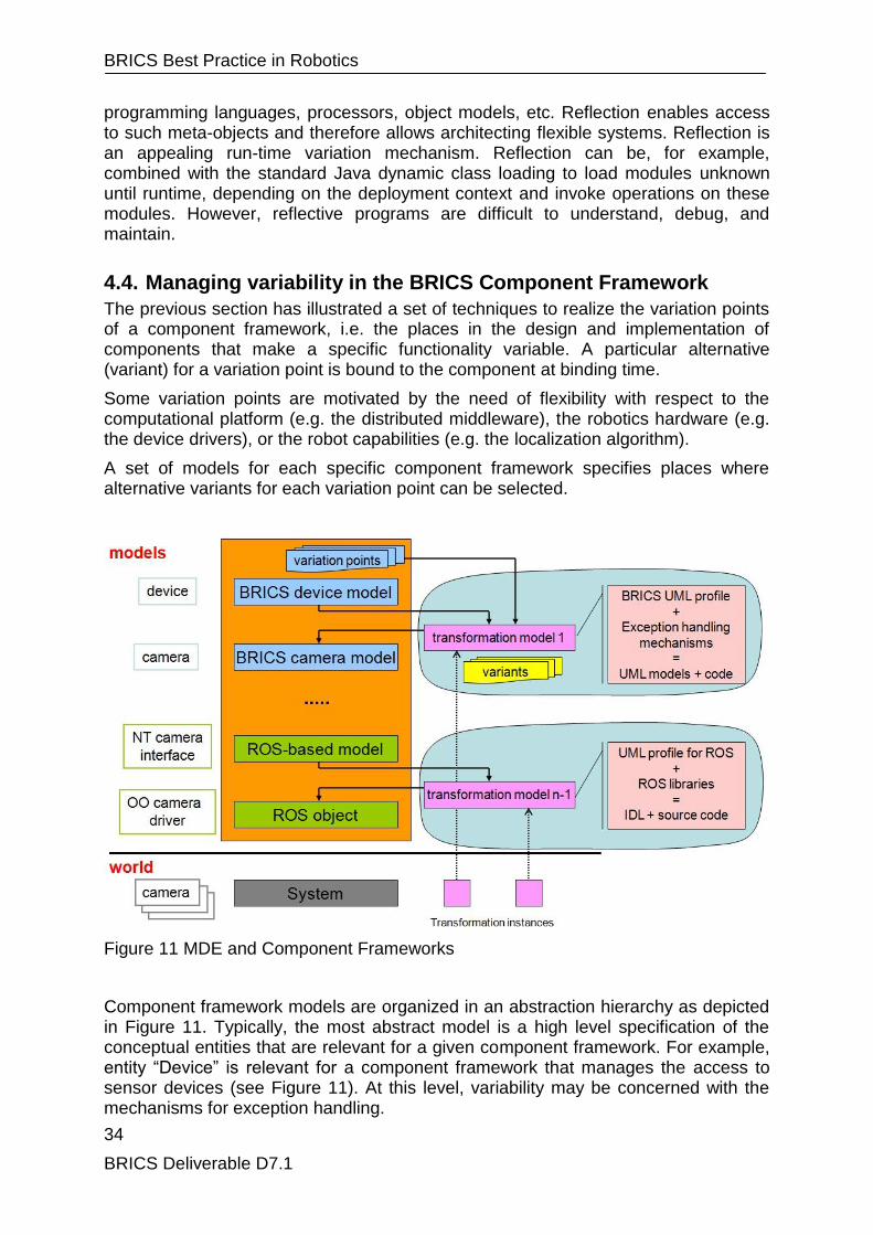
BRICS Best Practice in Robotics
34
BRICS Deliverable D7.1
programming languages, processors, object models, etc. Reflection enables access to such meta-objects and therefore allows architecting flexible systems. Reflection is an appealing run-time variation mechanism. Reflection can be, for example, combined with the standard Java dynamic class loading to load modules unknown until runtime, depending on the deployment context and invoke operations on these modules. However, reflective programs are difficult to understand, debug, and maintain.
4.4. Managing variability in the BRICS Component Framework
The previous section has illustrated a set of techniques to realize the variation points of a component framework, i.e. the places in the design and implementation of components that make a specific functionality variable. A particular alternative (variant) for a variation point is bound to the component at binding time.
Some variation points are motivated by the need of flexibility with respect to the computational platform (e.g. the distributed middleware), the robotics hardware (e.g. the device drivers), or the robot capabilities (e.g. the localization algorithm).
A set of models for each specific component framework specifies places where alternative variants for each variation point can be selected.
Figure 11 MDE and Component Frameworks
Component framework models are organized in an abstraction hierarchy as depicted in Figure 11. Typically, the most abstract model is a high level specification of the conceptual entities that are relevant for a given component framework. For example, entity ―Device‖ is relevant for a component framework that manages the access to sensor devices (see Figure 11). At this level, variability may be concerned with the mechanisms for exception handling.

BRICS Best Practice in Robotics
35
BRICS Deliverable D7.1
For the design of a specific component, the ―Device‖ entity can then be mapped to a more concrete ―Camera‖ device for which a specific device driver needs to be selected or implemented.
Finally, the Camera component may be deployed on a distributed environment by selecting the appropriate distributed middleware.
Model-driven Engineering tools support the semi-automatic transformation of the above hierarchy of models and the semi-automatic generation of source code.
The main benefit of using Model-driven Engineering tools for the configuration of component frameworks is that the management of the variation points is handled automatically by the transformation step and is not a concern for the application developer anymore.
This means that the application developer has to select one of possible variants for each variation point, while the model transformation until code generation is performed automatically.
Figure 12 shows an example, where a model-driven configuration management tool can help the application developer in the selection of appropriate variants when constraints must be enforced between related variation points. In this example, two variation points are represented, namely ―compression algorithm‖ and ―image format‖. The selection of a variant for one of the two variation points restricts the selection of the corresponding variant for the other variation point.
Figure 12 Support for Variability Management
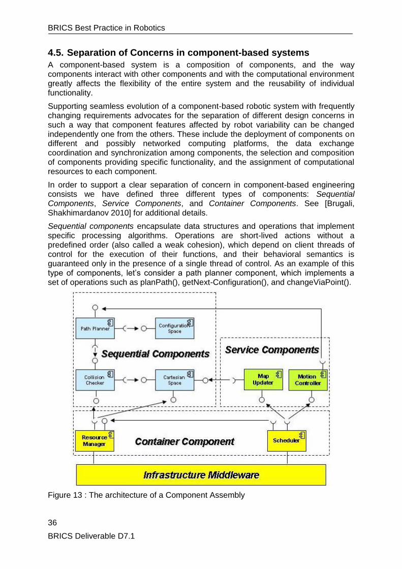
BRICS Best Practice in Robotics
36
BRICS Deliverable D7.1
4.5. Separation of Concerns in component-based systems
A component-based system is a composition of components, and the way components interact with other components and with the computational environment greatly affects the flexibility of the entire system and the reusability of individual functionality.
Supporting seamless evolution of a component-based robotic system with frequently changing requirements advocates for the separation of different design concerns in such a way that component features affected by robot variability can be changed independently one from the others. These include the deployment of components on different and possibly networked computing platforms, the data exchange coordination and synchronization among components, the selection and composition of components providing specific functionality, and the assignment of computational resources to each component.
In order to support a clear separation of concern in component-based engineering consists we have defined three different types of components: Sequential Components, Service Components, and Container Components. See [Brugali, Shakhimardanov 2010] for additional details.
Sequential components encapsulate data structures and operations that implement specific processing algorithms. Operations are short-lived actions without a predefined order (also called a weak cohesion), which depend on client threads of control for the execution of their functions, and their behavioral semantics is guaranteed only in the presence of a single thread of control. As an example of this type of components, let‘s consider a path planner component, which implements a set of operations such as planPath(), getNext-Configuration(), and changeViaPoint().
Figure 13 : The architecture of a Component Assembly

BRICS Best Practice in Robotics
37
BRICS Deliverable D7.1
Service components represent independent sequential execution threads of control. They offer the protected environment to fine grain concurrency, hide local data from other threads, maintain a symbolic state value, and broadcast events with the incoming state name every time a state transition occurs. Typically, service components implement the logic and embed the dynamic specification of robot control activities, such as closing the loop between sensors and actuators for motion control or notifying the robot navigation subsystem when obstacles are detected.
Container components provide the environment for the concurrent threads and encapsulate the shared resources. Container components possess, create, and internally manage one or more independent threads of control that govern the execution of their services. They are structured as software frameworks composed of services that provide the run-time support to guarantee extra-functional properties by means of mechanisms for resource management, service scheduling, and quality-of-service (QoS) negotiation [Gobel et al. 2004]. Figure 13 shows two services for 1) managing computational resources (resource manager) and 2) executing more than a single service concurrently (scheduler). The resource manager implements mechanisms for admission and reservation of system resources, such as CPU time, memory, communication devices, and robotics devices (sensors and actuators). The (optimal) allocation of resources to service components over time is a scheduling problem. The scheduler has the capability of managing the temporal constraints regarding the RT- and non-RTexecution of concurrent services.
Container components support the so-called inversion of control: they act as clients of sequential and service components and execute their operations when external events occur. For this purpose, sequential and service components implement standard interfaces, i.e., for resource management and scheduling. Container components hide the interfaces of run-time services provided by the underlying infrastructure middleware from component developers and instead automatically invoke them using developer-specified policies, thus eliminating coupling of sequential and service components with the platform-specific environment and enhancing their reusability.
The architectural distinction in three different component types supports independent evolution of heterogeneous technologies.
Container components are to a great extent middleware-specific (e.g., with respect to the support to threading, synchronization, and communication provided by the underlying run-time infrastructure) and functionality independent.
Sequential components should conveniently be designed to be middleware- and application independent. They may implement algorithms that, to some extent, are tightly coupled to specific robotic hardware, operational environment, and robotic task.
Service components are mostly functionality- and application- specific (i.e., they implement tasks that use specific robotic resources and must satisfy the specific timing requirements).
A set of sequential, service, and container components all together form a component assembly. Sequential components are typically deployed as binary files as they are intended to be reused, without changing the source code, within the applications developed by third parties. Service components implement the control logic of the application and are thus developed by adapting and extending a library of
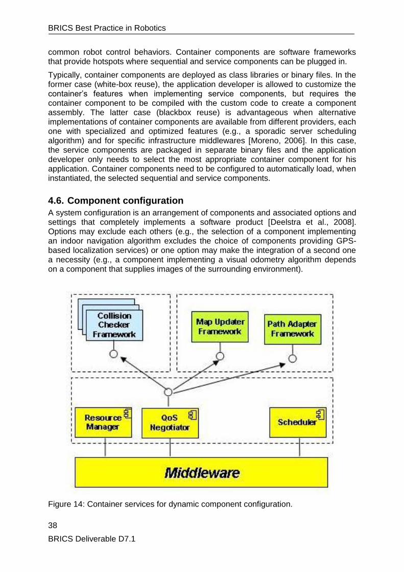
BRICS Best Practice in Robotics
38
BRICS Deliverable D7.1
common robot control behaviors. Container components are software frameworks that provide hotspots where sequential and service components can be plugged in.
Typically, container components are deployed as class libraries or binary files. In the former case (white-box reuse), the application developer is allowed to customize the container‘s features when implementing service components, but requires the container component to be compiled with the custom code to create a component assembly. The latter case (blackbox reuse) is advantageous when alternative implementations of container components are available from different providers, each one with specialized and optimized features (e.g., a sporadic server scheduling algorithm) and for specific infrastructure middlewares [Moreno, 2006]. In this case, the service components are packaged in separate binary files and the application developer only needs to select the most appropriate container component for his application. Container components need to be configured to automatically load, when instantiated, the selected sequential and service components.
4.6. Component configuration
A system configuration is an arrangement of components and associated options and settings that completely implements a software product [Deelstra et al., 2008]. Options may exclude each others (e.g., the selection of a component implementing an indoor navigation algorithm excludes the choice of components providing GPS-based localization services) or one option may make the integration of a second one a necessity (e.g., a component implementing a visual odometry algorithm depends on a component that supplies images of the surrounding environment).
Figure 14: Container services for dynamic component configuration.

BRICS Best Practice in Robotics
39
BRICS Deliverable D7.1
Hence, only a subset of all combinations is the admissible configuration. In [Gacek et al., 2001], the options are classified into five categories:
mandatory,
optional,
alternative,
mutually inclusive, and
mutually exclusive.
Most variation points are bound at deployment time, but there may still be variation points that are bound only at run time. This flexibility enables the dynamic reconfiguration of the component system according to the execution context.
4.6.1. Intra-assembly configuration
Several realizations of the each sequential or service component specification can be deployed as part of the same component assembly. As an example, Figure 14 depicts the structure of the motion planner component assembly, which encapsulates a variety of sequential components implementing algorithms for collision checking with different extra-functional properties, such as efficiency, performance, completeness, and exception handling. These properties are also called software qualities. The quality of a component executing a service is called QoS.
The quality of a component depends on both the specific implementation of the provided functionality and the availability of required resources. For example, the completeness of probabilistic motion planning algorithms increases with the processing time; similarly, the accuracy of collision detection algorithms increases with the amount of available memory; the timeliness of a decentralized control algorithm varies with the network bandwidth.
It is thus clear that a component QoS depends on the execution environment, which is not known when the component is developed. At deployment time, the application developer can select the components taking into account the worst case of resource usage, but the selection could be limited
and the worst case assumption is not applicable. A better approach differs with the selection of the more adequate components at run time when the actual execution context is known. The selection can then be based on the total amount of system resources, the set of available component implementations, and the most appropriate level of QoS for each component according to the application requirements.
A system is QoS aware if it is able to trade quality in one dimension with another [Wergeland, 2007], e.g., completeness and efficiency. In an architectural perspective, QoS awareness is achieved by means of a QoS negotiator component that implements data structures and mechanisms for QoSmanagement, and in particular:
QoS profile: Every sequential and service component implements a provided interface that allows the QoS negotiations to access the component‘s QoS profile. This profile consists of offered and required quality statements as well as the resource demand. In [Gobel et al., 2004], quality statements are expressed in the CQML+ language, as Boolean expression using current values of some system property (e.g., response time).

BRICS Best Practice in Robotics
40
BRICS Deliverable D7.1
QoS negotiation: The set of component assemblies in a system negotiate the quality level of the service provided by their constituent components, possibly involving the cost for the service. The result of such a negotiation is a contract, which defines the limits on the QoS characteristics that each service must operate within. In [Gobel et al., 2004], the negotiation process is centralized and managed by a specialized component called the contract manager.
Service planning: Each component assembly selects the best available implementation of sequential and service components according to the QoS contract. Service planning [Wergeland, 2007] enables optimized sharing of resources between concurrent services.
The QoS negotiation and service planning processes are triggered by changes in the QoS profile of the components in the system. For example, motion planning in a static cluttered environment requires algorithms that guarantee completeness even if computational time demanding. In contrast, more efficient algorithms are needed for motion planning when the robot moves in dynamic environments. Consequently, the actual configuration of component assemblies changes at run time.
4.6.2. Inter-assemly configuration
Complex systems are built by interconnecting different component assemblies at run time when their binaries are instantiated with configuration data that represent references to their communicating parties. The interactions among component assemblies can change dynamically at run time according to the availability of their services, that can vary during their execution because of hardware failures (e.g., of a robotic device), limited network bandwidth, and system overloading. In this context, configuration programming regards changing the state of a system as an activity performed at the level of interconnecting components rather than within the internal purely computational functionality of some component [Papadopoulos et a., 1998]. Several configuration and dynamic reconfiguration languages have been documented in the literature, such as Darwin/Regis [Kramer et al., 1990], POLYLITH [Purtilo, 1994], andRapide [Luckham et al., 1995], to name a few. In Wright [Allen et al., 1998], an architectural structure is represented as a graph of components and connectors. Both components and connectors have interfaces, which represent points of interaction.
Connectors identify the logical participants and encode the dynamism of the system configuration by explicitly identifying different patterns of interactions among components. For example, a connector may represent alternating configurations of a fault-tolerant client/server system, where multiple server components offer redundant services (e.g., camera-based or sonar-based obstacle avoidance) and are dynamically switched in case of failures (e.g., the camera stops functioning). A special component, called configurator, is responsible for achieving the changes to the architectural topology according to event generated by components notifying relevant state transitions, such as the activation or deactivation of component services.
More recently, service-oriented architectures (SOAs) [Erl, 2005] have been proposed as an architectural paradigm, in which the components are entities providing services described using a standard description language, the Web services description language (WSDL). Applications are built dynamically by discovering services
BRICS Best Practice in Robotics
41
BRICS Deliverable D7.1
available on a computer network that provide the required interfaces and assembling them on demand.
4.7. Component communication
Communication deals with the exchange of data [Radestock et al., 1996]. Components of a robot control architecture have to communicate with each other to cooperate. Communication can be imperative, as in the case of a command issued by one component to another, or can be reactive, as in the case of event notification.
Two communication mechanisms are deeply rooted in object-oriented programming, namely the caller/provider mechanism, which is involved when an object invokes another object method, and the broadcaster/listener mechanism, which gives objects the capability of broadcasting and listening to events.
One fundamental issue in communicating is that some sort of visibility [Booch, 1990] must exist among the parties. The communicating components, which are part of the same component assembly, reside in the same address space, thus the caller holds a reference to the provider (its memory address) to invoke its operations.
Visibility and flow of information can move in the same or opposite direction with respect to the communicating components, according to the mechanism used to implement the communication. The caller has the visibility of the provider and initiates the unidirectional (command) or bidirectional (query and response) exchange of information. The listener has the visibility of the broadcaster, which notifies events to registered listeners.
Visibility implies dependency with respect to changes, and hence, it has consequences on the reusability of components. To avoid the propagation of local changes to the entire architecture, visibility relationships have to be designed, taking into account the possible evolution of the system, and visibility loops should be avoided between components that evolve independently.
According to the component architecture described in the previous section, sequential components embed functionality that are common to most robotic applications and implement stable and harmonized interfaces defined by robotics experts. In contrast, service components are more application specific and are implemented by system integrators according to the functional requirements of each specific system. Thus, it is convenient to establish a communication pattern between a service component and a sequential component, where the former plays the role of caller and/or listener and the latter plays the role of provider and/or broadcaster.
4.7.1. Component Decoupling
Service components belonging to different assembly components are loosely coupled entities that reside on networked components and whose relationships can change dynamically at run time. The degree of decoupling between distributed service components can be analyzed along the three dimensions that have been thoroughly described in [Eugster et al., 2003], namely, space decoupling, time decoupling, and synchronization decoupling.
Space decoupling means that interacting components do not need to know each other, i.e., the caller does not hold a reference to the provider, and the publisher does not know which subscribers are participating in the interaction.

BRICS Best Practice in Robotics
42
BRICS Deliverable D7.1
Space decoupling increases the component reusability by removing explicit dependencies to specific components and system flexibility by supporting dynamic replacement and interconnection of individual components.
Time decoupling is enforced when the interacting components do not need to be actively participating in the interaction at the same time. Time decoupling enhances system reliability by making inter-component communication more robust to network failures.
Synchronization decoupling guarantees that callers, providers, publishers, and subscribers are not blocked while producing or consuming data and events. Asynchronous communication is a fundamental requirement of robotic control systems, where several activities process data (e.g., sensor measurements) concurrently and independently.
These kinds of decoupling are realized by means of services provided by container components that represent neutral mediators between interacting components. From an architectural perspective, such mediation services are usually represented by communication ports (see Figure 15).
Communication ports rely on a middleware framework to exchange data and events through the network. Most common middlewares provide concrete implementations of various communication ports. Nevertheless, it is convenient to explicitly represent them at a more abstract architectural level because, in embedded systems, heavyweight middlewares cannot be exploited because of system-limited resources, and communication ports are more conveniently implemented using ad-hoc communication mechanisms, as described in [Corke et al., 2004]. In this case, the explicit representation of communication ports makes the properties of components‘ interaction more visible [Schreiner, 2007].
The following sections illustrate the two well-known distributed communication paradigms that support, to different degrees, component decoupling along the three dimensions described above, namely, remote method invocation (RMI) and publish/subscribe.
BRICS Best Practice in Robotics
43
BRICS Deliverable D7.1
Figure 15: Container services for distributed component interactions.
4.7.2. Remothe Method Invocation
The distribution paradigm adopted by some middleware frameworks like Object Management Group (OMG) common object request broker architecture (CORBA) and Java RMI consists in making remote invocations appear the same as local interactions. This is accomplished by means of two ancillary objects called the stub and skeleton.
The stub is a surrogate (proxy) of the provider and resides in the caller‘s address space. It offers the same set of operations as the remote provider. The caller invokes the stub‘s operations as if it were the provider itself. The stub is in charge of marshaling the caller‘s request and transmitting it through the network.
The skeleton resides in the provider‘s address space and is in charge of receiving and unmarshaling the caller‘s request and invoking the corresponding providers operation. Similarly, the matched pair stub/skeleton is used to transmit the result of a provider operation to the caller through the network.
Figure 15 shows the two component assemblies (the caller on the left-hand side and the provider at the right-hand side). The motion controller generates and controls the execution of robot trajectories. It delegates the definition of the corresponding motion paths to the path generator, which is hosted in a separate (possibly distributed) assembly. The stub port implements a provided interface that defines standard operations for common interaction patterns, such as push(data d), pull(data d), and request(query q, response r). These operations are invoked by themotion controller to interact with the path generator. A corresponding set of operations are defined in the required interface of the skeleton port and are implemented by the path generator.
The RMI paradigm imposes space coupling between the parties and is thus conveniently used for stable point-to-point interactions. This means that the motion controller interacts with a specific instance of path generator. It also introduces time coupling between the interacting parties because both stub and skeleton services should be active at the same time. The synchronization decoupling depends on how the provider‘s operations are implemented, namely as synchronous, asynchronous, or deferred-synchronous service requests. Synchronous requests block the caller until the provider has completed the execution of the requested operation and are typically usedwhen a response from the provider is required immediately or within some (application-specific) period of time, because a lack of response may prevent the caller from continuing its execution. Asynchronous requests return immediately after the provider has received the parameters of the invoked operation. Deferred-synchronous requests return a token that allows the caller to retrieve the operation return value when needed.
4.7.3. Publish/Subscribe
The publish/subscribe interaction paradigm provides decoupling of distributed components in all time, space, and synchronization dimensions. Messages, called events, are exchanged between publishers and subscribers in an asynchronous manner without the need for the interacting parties to know each other and to participate to the interaction at the same time.
BRICS Best Practice in Robotics
44
BRICS Deliverable D7.1
An event is typically characterized by three information.
The type characterizes events in such a way that subscribers can recognize the events they are interested in. Typically, it corresponds to an information subject that is identified by one or more keywords. For example, the navigator component is interested in alarm events, indicating that an unexpected obstacle has been detected along the robot path. Every device component processing sensory data has to be programmed to notify this type of event.
The payload data contains application-specific information. For example, a publisher component (e.g., the motion controller) may issue an event that indicates a change in its internal state (e.g., motion done).
The timestamp indicates the instant when the event has been generated.
Optional information may indicate the priority of the event, the issuer identifier, and the expiration time. Full decoupling is achieved by means of communication ports that implement, store, and forward mechanisms both in the publisher‘s and subscriber‘s containers so that the communication appears asynchronous and anonymous to interacting service components.
The publisher posts events in the local container‘s communication port, which asynchronously (i.e., by means of a dedicated thread) forwards them to the communication port of registered subscribers. When an event is received, an event handler notifies the subscribers asynchronously. In case of network failures or unavailability of a subscriber, the publisher‘s communication port stores the event until it can be notified correctly.
For example, in Figure 15, the path generator plays the role of a publisher and notifies the motion controller (the subscriber) that the generation of a new path has been completed.
Subscriptions can be handled in two ways. If the publisher‘s communication port maintains the list of subscribers to its events, it can establish a point-to-point connection with each subscriber when an event needs to be notified. In this case, publishers advertise the type of event they intend to notify to inform interested subscribers, which register themselves with the publisher. Alternatively, the publisher‘s communication port sends events through the network using hardware multicast facilities like IP multicast. Every subscriber in the subnetwork receives the event, which is filtered by the local communication port according to the subscriber‘s criteria.
4.8. Component coordination
Coordination is concerned with the interaction of the various system components [Radestock et al., 1996]. Service components embed the control logic of a robot control application. They cooperate with each other locally or through a communication network to achieve a common goal according to the robot control architecture and compete for the use of shared resources, such as the robot sensors and actuators, the robot functionality offered by sequential components, and the computer processing and communication resources.
Cooperation and competition are forms of interactions among concurrent activities, implemented as sequential threads of control encapsulated inside service components. Concurrency means that computations in the system overlap in time

BRICS Best Practice in Robotics
45
BRICS Deliverable D7.1
[Arbab, 1998] and are interleaved with one another on a single processor. Correct interleaving of concurrent activities is governed by algorithms called interaction protocols [Rust, 2005], such as mutual exclusion protocols, which ensure that a non-sharable resource is only used by one activity at a time and that an activity that wants to access the nonsharable resource will get access to it eventually.
Interaction protocols are implemented using synchronization mechanisms such as locks, semaphores, and event handlers. An event handler in an event-driven control environment is the most commonly used synchronization mechanism. It blocks the current thread until an event is received from one of the objects it monitors. Every time a thread calls the waitEvent(Symbol filter) method of the event handler, it is suspended until the event named filter is raised.When one of the events to which the event handler is attached is raised, the threads waiting for this event are awakened in turn and continue their execution.
Modelling and designing complex concurrent systems is a difficult task, which is even more exacerbated in component based system design, where abstraction, encapsulation, and modularity are the main concerns. Components encapsulate and hide to the rest of the system how computations are ordered in sequential threads and how and when computations alter the system state. The consequence of improper management of the order and containment relationships in a complex, concurrent system is a deadlock [Davis, 2000].
4.8.1. Coordination Models and Languages
To alleviate the difficulties of designing complex concurrent systems, coordination languages and models have been proposed as valid tools to managing the interaction among concurrent components [Papadopoulos, 1998].
Coordination languages and models fall into one of two major categories of coordination programming, namely, either data-driven or control-driven coordination. Data-driven coordination models define the state of the computation of the entire system at any moment in time in terms of the actual system configuration and the data exchanged by system components through a shared tuple space [Gelernter, 1985]. A tuple is an ordered list of structured data, has an existence which is independent of its producer, and it is equally accessible to all components until it is explicitly withdrawn by some component. Typical examples of data-oriented applications are transactional information systems. In contrast, control-driven coordination models define the state of the computation of the entire system at any moment in time in terms of the current internal state of each component. Components observe state transitions in the systems by listening to events notified by other components.
The two categories of coordination languages also differ in terms of programming style. Data-driven languages like LINDA [Carriero et al., 1989] generally lead to intermixing of coordination primitives with computation code, making the coordination model and the coordination protocol implicit. In contrast, control-driven models enable a clear and complete separation of coordination and computation concerns. This is usually achieved by using different languages for expressing computation and coordination and by developing coordination components separately and independently of the computation components they coordinate.

BRICS Best Practice in Robotics
46
BRICS Deliverable D7.1
An example of coordination language is Manifold [Papadopoulos, 1998], a strongly typed, block-structured, event-driven language, meant for writing coordinator program modules.
4.8.2. Connectors as Coordination Components
Recently, the relations between software architectures and coordination models have been explicitly studied [Inverardi et al., 2003], with the goal of profitably and coherently exploiting both approaches to component-based system design.
Connectors represent first-class architectural entities embodying component interaction. For example, the UniCon language [Shaw et al., 1996] defines a set of predefined connector types that correspond to common communication primitives. In the Wright language [Allen et al, 1997], the interactions among components are fully specified by the user, and the complex interactions can be expressed by nested connector types.
The taxonomy of software connectors presented in [Mehta et al., 2000] identifies and analyzes the basic tasks a connector should perform, such as
interface adaptation and data conversion for components that have not been originally designed to interoperate
control and data transfer between local and remote components
communication intercepting for implementing various filters (e.g., cryptography, data compression, load monitoring, etc.).
access coordination and ordering of method calls on a component interface.
The connector task indicated in the last item is particularly relevant to the discussion on component coordination. The permitted orderings of method calls on a component interface are usually determined by a behavioural specification of the component, which represents the contract between a component and its client and assumes the form of a coordination protocol. For example, a coordination protocol may specify that two operations of a component interface must be invoked immediately one after the completion of the other.
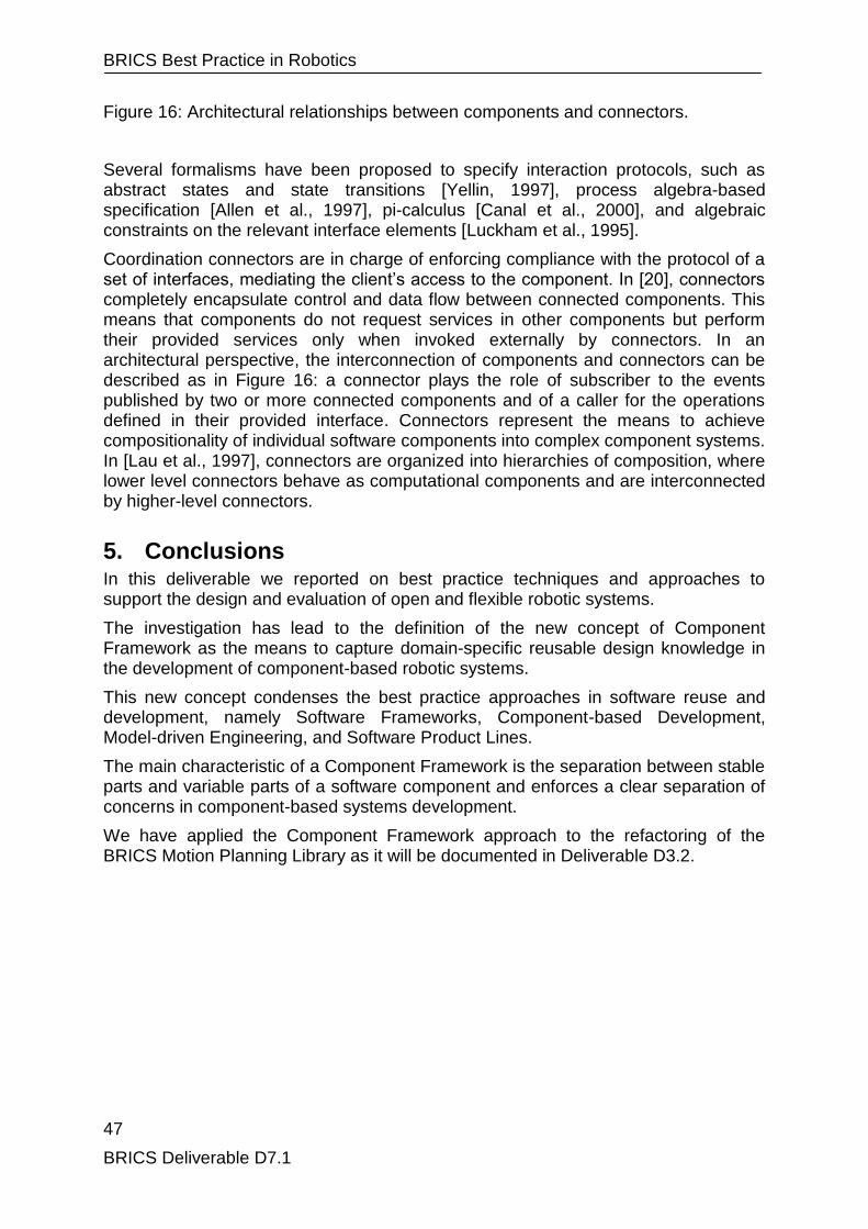
BRICS Best Practice in Robotics
47
BRICS Deliverable D7.1
Figure 16: Architectural relationships between components and connectors.
Several formalisms have been proposed to specify interaction protocols, such as abstract states and state transitions [Yellin, 1997], process algebra-based specification [Allen et al., 1997], pi-calculus [Canal et al., 2000], and algebraic constraints on the relevant interface elements [Luckham et al., 1995].
Coordination connectors are in charge of enforcing compliance with the protocol of a set of interfaces, mediating the client‘s access to the component. In [20], connectors completely encapsulate control and data flow between connected components. This means that components do not request services in other components but perform their provided services only when invoked externally by connectors. In an architectural perspective, the interconnection of components and connectors can be described as in Figure 16: a connector plays the role of subscriber to the events published by two or more connected components and of a caller for the operations defined in their provided interface. Connectors represent the means to achieve compositionality of individual software components into complex component systems. In [Lau et al., 1997], connectors are organized into hierarchies of composition, where lower level connectors behave as computational components and are interconnected by higher-level connectors.
5. Conclusions In this deliverable we reported on best practice techniques and approaches to support the design and evaluation of open and flexible robotic systems.
The investigation has lead to the definition of the new concept of Component Framework as the means to capture domain-specific reusable design knowledge in the development of component-based robotic systems.
This new concept condenses the best practice approaches in software reuse and development, namely Software Frameworks, Component-based Development, Model-driven Engineering, and Software Product Lines.
The main characteristic of a Component Framework is the separation between stable parts and variable parts of a software component and enforces a clear separation of concerns in component-based systems development.
We have applied the Component Framework approach to the refactoring of the BRICS Motion Planning Library as it will be documented in Deliverable D3.2.
BRICS Best Practice in Robotics
48
BRICS Deliverable D7.1
6. References [ALIVE, 2010] FP7 EU-ICT ALIVE project (Coordination, organisation and model driven approaches for dynamic, flexible, robust software and services engineering, http://www.ist-alive.eu)
[Allen et al, 1997] R. Allen and D. Garlan, ‗‗A formal basis for architectural connection,‘‘ ACM Trans. Software Engineering and Methodology, vol. 6, no. 3, pp. 213–249, July 1997.
[Allen et al., 1998] R. Allen, R. Douence, and D. Garlan, ‗‗Specifying and analyzing dynamic software architectures,‘‘ in Proc. 1998 Conf. Fundamental Approaches to Software Engineering (FASE‘98), Lisbon, Portugal, Mar. 1998, pp. 21–37.
[Anastasopoulos et al., 2001] M. Anastasopoulos and C. Gacek, ‗‗Implementing product line variabilities,‘‘ SIGSOFT Softw. Eng. Notes, vol. 26, no. 3, pp. 109–117, 2001.
[Arbab, 1998] F. Arbab, ‗‗What do you mean, coordination?‘‘ Bulletin of the Dutch Association for Theoretical Computer Science, pp. 11–22, Mar. 1998.
[Baeuml and Hirzinger, 2008] B. Baeuml and G. Hirzinger, ‗‗When hard realtime matters: Software for complex mechatronic systems,‘‘ Robot. Autonom. Syst., vol. 56, no. 1, pp. 5–13, 2008.
[Barr, 2000] Adam Barr, Proudly Serving My Corporate Masters: What I Learned in Ten Years as a Microsoft Programmer, IUniverse (December 26, 2000), ISBN-13: 978-0595161287
[Bass, 1999] L. Bass, P. Clements, and R. Kazman, Software Architecture in Practice. Reading, MA: Addison Wesley, 1999.
[Bencomo et al., 2008] Bencomo, N., Grace, P., Flores, C., Hughes, D., Blair, G.: Genie: Supporting the model driven development of reflective, component-based adaptive systems. In: ICSE. (2008) 811-814
[Bennet et al, 2000] Bennet, K. H., Rajlick, V. T. , Software Maintenance and Evolution: a Roadmap, Proceedings of the Conference on The Future of Software Engineering, 2000.
[Blair, 2009] Gordon Blair, Nelly Bencomo and Robert B. France. [email protected]. IEEE Computer, 2009.
[Booch, 1990] G. Booch, Object-Oriented Design with Applications. Redwood City, CA: Benjamin Cummings, 1990.
[Brugali et al. 1997] Brugali D, Menga G, Aarsten A. The framework lifespan. Communications of the ACM 1997; 40(10):65–68.
[Brugali and Prassler, 2009] D. Brugali and E. Prassler, ‗‗Software engineering for robotics,‘‘ Special Issue of the IEEE Robot. Automat. Mag., vol. 16, no. 1, pp. 9, 15, Mar. 2009.
[Brugali, Scandurra 2009] D. Brugali and P. Scandurra, ―Component-based Robotic Engineering – Part I‖, IEEE RAM December 2009
[Brugali, Shakhimardanov 2010] D. Brugali and A. Shakhimardanov, ―Component-based Robotic Engineering – Part II‖, IEEE RAM March 2010

BRICS Best Practice in Robotics
49
BRICS Deliverable D7.1
[Brugali et al. 2010] Davide Brugali, Walter Nowak, Luca Gherardi, Alexey Zakharov, ―Component-based Refactoring of Motion Planning Libraries‖, IEEE Int. Conference on Intelligent Robotic Systems (IROS 2010), Taipei, Taiwan, October 2010
[Canal, 2000] C. Canal, L. Fuentes, J. Troya, and A. Vallecillo, ‗‗Extending corba interfaces with p-calculus for protocol compatibility,‘‘ in Proc. Int. Conf. Technology of Object-Oriented Languages, 2000, p. 208.
[Carriero et al., 1989] N. Carriero and D. Gelernter, ‗‗Linda in context,‘‘ Commun. ACM, vol. 32, no. 4, pp. 444–458, 1989.
[Christensen et al., 2004] W. Li, H. I. Christensen, A. Orebäck, D. Chen, ―An Architecture for Indoor Navigation‖, ICRA 2004
[Clements and Northrop, 2001] Clements, P., Northrop, L., 2001. Software Product Lines: Practices and Patterns. In: SEI Series in Software Engineering. Addison-Wesley. ISBN: 0-201-70332-7.
[Clien and Girou, 2000] Clien M. & Girou M. Enduring Business Themes. CACM, Vol 43(5), May 2000 pp. 101-106
[Coplien, 1998] J. Coplien, D. Hoffman, and D. Weiss. Commonality and variability in software engineering. IEEE Software, 15(6), 1998
[Corke et al., 2004] P. Corke, P. Sikka, J. Roberts, and E. Duff, ‗‗Ddx: A distributed software architecture for robotic systems,‘‘ in Proc. Australian Conf. Robotics and Automation, Canberra, A.C.T., Dec. 2004.
[Davis, 2000] J. S. Davis II, ‗‗Order and containment in concurrent system design,‘‘ Ph.D. dissertation, Univ. of California, Berkeley, 2000.
[Deelstra et al., 2008] S. K. Deelstra and M. Sinnema, ‗‗Managing the complexity of variability in software product families,‘‘ Ph.D. dissertation, Rijksuniversiteit Groningen, 2008.
[DIVA, 2010] FP7 EU-ICT DiVA (Dynamic Variability in complex, Adaptive systems); http://www.ict-diva.eu
[Elkhodary et al., 2009] Ahmed Elkhodary, Sam Malek, Naeem Esfahani: On the Role of Features in Analyzing the Architecture of Self-Adaptive Software Systems, 4th Workshop on [email protected] at MODELS 09
[Erl, 2005] T. Erl, Service-Oriented Architecture: Concepts, Technology, and Design. Upper Saddle River, NJ: Prentice Hall, 2005.
[Eugster et al., 2003] P. T. Eugster, P. A. Felber, R. Guerraoui, and A.-M. Kermarrec, ‗‗The many faces of publish/subscribe,‘‘ ACM Comput. Surv., vol. 35, no. 2, pp. 114–131, 2003.
[Ezran, 1998] M. Ezran, M. Moriso, and C. Tully, Practical Software Reuse—The Essential Guide. Paris: Freelife Publ: ESSI Surprise Project Book, 1998.
[Fayad, 2002] Fayad M.E. Accomplishing Software Stability. CACM 45(1), 2002
[Fowler et al., 2002] Martin Fowler, Kent Beck, John Brant, William Opdyke, Don Roberts - Refactoring: Improving the design of existing code - Addison Wesley
[Gacek et al., 2001] C. Gacek and M. Anastasopoulos, ‗‗Implementing product line variabilities,‘‘ SIGSOFT Softw. Eng. Notes, vol. 26, no. 3, pp. 109–117, 2001.
BRICS Best Practice in Robotics
50
BRICS Deliverable D7.1
[Gamma et al., 1995] E. Gamma, R. Helm, R. Johnson, and J. Vlissides. Design Patterns: Elements of Reusable Object-Oriented Software. Reading, MA: Addison-Wesley, 1995.
[Gelernter, 1985] D. Gelernter, ‗‗Generative communication in linda,‘‘ ACM Trans. Program. Lang. Syst., vol. 7, no. 1, pp. 80–112, 1985.
[Gobel et al., 2004] S. Gobel, C. Pohl, R. Aigner, M. Pohlack, S. R€ottger, and S. Zschaler, ‗‗The COMQUAD component container architecture,‘‘ in Proc. 4th Working IEEE/IFIP Conf. Software Architecture (WICSA), J. Magee, C. Szyperski, and J. Bosch, Eds., June 2004, pp. 315–318.
[Inverardi et al., 2003] P. Inverardi and H. Muccini, ‗‗Software architectures and coordination models,‘‘ J. Supercomput., vol. 24, no. 2, pp. 141–149, 2003.
[Johnson, 1992] Johnson, R. 1992, Documenting frameworks using patterns. In Proceedings of OOPSLA‘92, 1992
[Johnson, 1988] R. Johnson and B. Foote, ‗‗Designing reusable classes,‘‘ J. Object-Oriented Program., vol. 1, no. 2, pp. 22–35, 1988.
[Kerievsky, 2004] Joshua Kerievsky - Refactoring to patterns - Addison Wesley - 2004.
[Kim et al., 2009] M. Kim, S. Kim, S. Park, M. Choi, M. Kim and H. Gomaa. ―Service Robot Software Development with the COMET/UML Method‖, IEEE Robotics and Automation Magazine, March 2009
[Kramer et al., 1990] J. Kramer, J. Magee, and A. Finkelstein, ‗‗A constructive approach to the design of distributed systems,‘‘ in Proc. 10th Int. Conf. Distributed Computing Systems (ICDCS 1990). Paris, France: IEEE Computer Society, May 28–June 1, 1990, pp. 580–587.
[Lau et al., 2007] K.-K. Lau, L. Ling, P. V. Elizondo, and V. Ukis, ‗‗Composite connectors for composing software components,‘‘ in Proc. 6th Int. Symp. Software Composition (LNCS 4829), M. Lumpe and W. Vanderperren, Eds. Berlin, Heidelberg: Springer-Verlag, 2007, pp. 266–280.
[Luckham et al., 1995] D. C. Luckham, J. J. Kenney, L. M. Augustin, J. Vera, D. Bryan, and W. Mann, ‗‗Specification and analysis of system architecture using rapide,‘‘IEEE Trans. Softw. Eng., vol. 21, no. 4, pp. 336–355, 1995.
[Mandelbaum et al., 1990] Mandelbaum, M. and Buzacott, J., 1990. Flexibility and decision-making. European Journal of Operational Research,44 (1), 17–27.
[Mangili, 2009] Michele Mangili, ―Supporting software evolution through a diagnostic approach of maintainability‖, Bachelor Thesis, Università degli Studi di Bergamo, 2009
[Mark, 2005] Mark, G.T., 2005. Incorporating flexibility into system design: a novel framework and illustrated developments. Thesis (Masters of Science). Department of Aeronautics and Astronautics, Massachusetts Institute of Technology.
[Mataric, 2002] M. J. Mataric, ―Situated robotics,‖ Encyclopedia of Cognitive Science, 2002. [Online]. Available: http://robotics.usc.edu/ maja/publications/sitrob.pdf
BRICS Best Practice in Robotics
51
BRICS Deliverable D7.1
[Mehta et al., 2000] N. R. Mehta, N. Medvidovic, and S. Phadke, ‗‗Towards a taxonomy of software connectors,‘‘ in Proc. 22nd Int. Conf. Software Engineering, ICSE ‘00. New York, NY: ACM, 2000, pp. 178–187.
[Moreno, 2006] G. A. Moreno, ‗‗Creating custom containers with generative techniques,‘‘ in Proc. 5th Int. Conf. Generative Programming and Component Engineering (GPCE ‘06). New York, NY, ACM, 2006, pp. 29–38.
[Nesnas 2007] I. A. Nesnas, ‗‗The claraty project: Coping with hardware and software heterogeneity,‘‘ in Software Engineering for Experimental Robotics (Springer Tracts in Advanced Robotics, vol. 30), D. Brugali, Ed. Berlin, Springer-Verlag, Apr. 2007.
[Papadopoulos et a., 1998] G. A. Papadopoulos and F. Arbab, ‗‗Coordination models and languages,‘‘ Adv. Comput., vol. 46, no. 1, pp. 330–401, 1998.
[Poulin, 1996] J. Poulin, Measuring Software Reuse: Principles, Practices, and Economic Models. Reading, MA: Addison-Wesley, 1996.
[Purtilo, 1994] J. M. Purtilo, ‗‗The polylith software bus,‘‘ ACM Trans. Program. Lang. Syst., vol. 16, no. 1, pp. 151–174, 1994.
[Radestock et al., 1996] M. Radestock and S. Eisenbach, ‗‗Coordination in evolving systems,‘‘ in Proc. Int. Workshop Trends in Distributed Systems CORBA and Beyond (Springer LNCS, vol. 1161), 1996, pp. 162–176.
[Rosemann et al. 2006] M. Rosemann and J. Recker. Context-aware process design exploring the extrinsic drivers for process flexibility Proc. BPMDS. (CEURWorkshop, vol. 236), G. Regev, P. Soffer, and R. Schmidt, Eds. pp. 149–158, 2006
[Rust, 2005] H. Rust, ‗‗Concurrency and reactivity: Interleaving,‘‘ in Operational Semantics for Timed Systems (Series Lecture Notes in Computer Science, vol. 2456). Berlin, Heidelberg: Springer-Verlag, 2005, ch. 8, pp. 75–82.
[Saleh et al. 2003] Saleh, J.H., Newman, D.J. and Hastings, DE., 2003b. Flexibility in system design and implications for aerospace systems.Acta Astronautica, 53 (12), 927–944.
[Saleh et al., 2008] Joseph H. Saleh, Gregory Markb and Nicole C. Jordanc. Flexibility: a multi-disciplinary literature review and a research agenda for designing flexible engineering systems. Journal of Engineering Design, March 2008
[Salvaneschi, 2008] Salvaneschi, P., Piazzalunga, U., Engineering models and software quality models: an example and discussion, MiSE‘08 Workshop. ICSE 2008 proceedings, Leipzig, Germany, 2008.
[Schmidt, 2006] D. C. Schmidt, ‗‗Guest editor‘s introduction: Model-driven engineering,‘‘ Computer, vol. 39, no. 2, pp. 25–31, Feb. 2006.
[Schreiner, 2007] D. Schreiner and K. M. G€oschka, ‗‗Explicit connectors in component based software engineering for distributed embedded systems,‘‘ in Proc. 33rd Conf. Current Trends in Theory and Practice of Computer Science, SOFSEM ‘07. Berlin, Heidelberg: Springer-Verlag, 2007, pp. 923–934.
[Sethi and Sethi, 1990] Sethi, A.K. and Sethi, S.P., 1990. Flexibility in manufacturing: a survey. International Journal of Flexible Manufacturing Systems, 2 (4), 289–328.
BRICS Best Practice in Robotics
52
BRICS Deliverable D7.1
[Shaw et al., 1996] M. Shaw, R. DeLine, and G. Zelesnik, ‗‗Abstractions and implementations for architectural connections,‘‘ in Proc. 3rd Int. Conf. Configurable Distributed Systems, ICCDS ‘96, Washington, DC: IEEE Computer Society, 1996.
[Simpson, 2003] Simpson, T.W., 2003. Product platform design and customization: status and promise. In: ASME 2003 Design Engineering Technical Conferences and Computers and Information in Engineering Conference, 2–6 September 2003, Chicago, IL.
[Simpson et al. 2001] Simpson, T.W., Maier, J.R. and Mistree, F., 2001. Product platform design: method and application. Research in Engineering Design, 13 (1), 2–22.
[Szyperski, 2002] C. Szyperski, Component Software: Beyond Object-Oriented Programming. Reading, MA: Addison-Wesley, 2002.
[Yellin, 1997] D. M. Yellin and R. E. Strom, ‗‗Protocol specifications and component adaptors,‘‘ ACM Trans. Program. Lang. Syst., vol. 19, no. 2, pp. 292–333, 1997.
[Wergeland, 2007] O. M. Wergeland, ‗‗Service planning in a qos-aware component architecture,‘‘ Ph.D. dissertation, Univ. Oslo, 2007


![[AW]policy BRICS - ITD · กลุ่มประเทศ brics จะก่อให้เกิดประโยชน์ทางเศรษฐกิจกับไทย”](https://img.dokumen.tips/doc/110x75/5eb6589d95ac763ff45c6af5/awpolicy-brics-aaaaaaaaaaa-brics-aaaaaafaaaaaaaaaaaaaaoeaaaaaaaaaaaaaaaaaa.jpg)