Embed Size (px)
Citation preview

FAA Workshop on Best Practice in Adhesive Bonding
Max DavisPrincipal Research Scientist
Directorate General Technical AirworthinessRoyal Australian Air Force
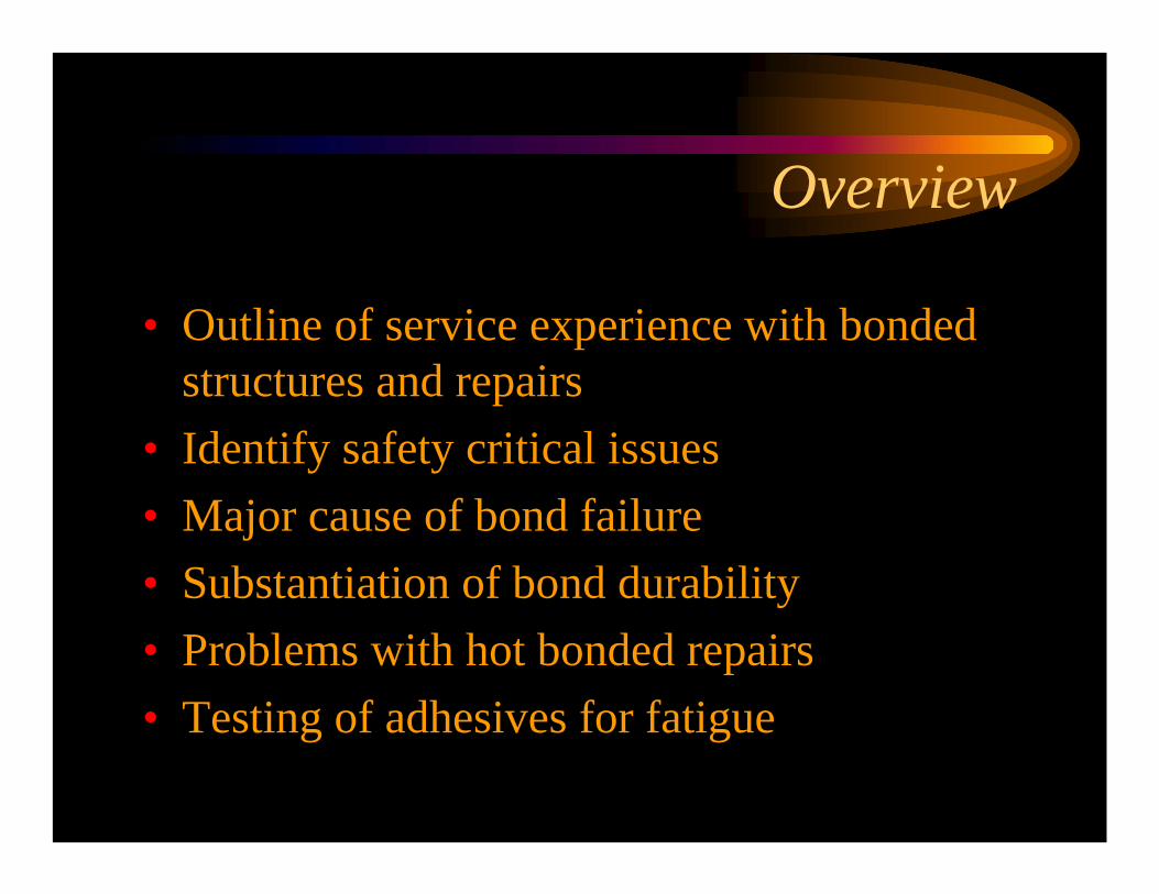
Overview
• Outline of service experience with bonded structures and repairs
• Identify safety critical issues• Major cause of bond failure• Substantiation of bond durability• Problems with hot bonded repairs• Testing of adhesives for fatigue
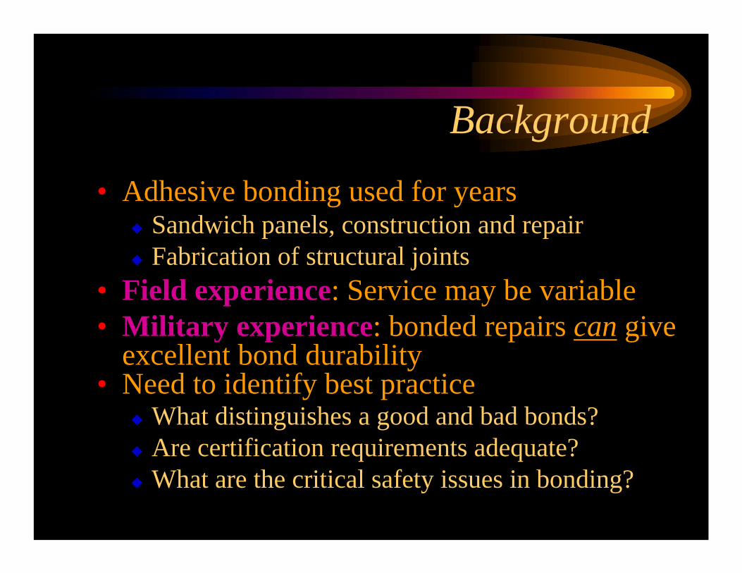
Background
• Adhesive bonding used for yearsSandwich panels, construction and repairFabrication of structural joints
• Field experience: Service may be variable• Military experience: bonded repairs can give
excellent bond durability • Need to identify best practice
What distinguishes a good and bad bonds?Are certification requirements adequate?What are the critical safety issues in bonding?

Military Repair Metal Bond Experience
• 1992 Survey: 42% of bonded repairs were to fix a defective repair
• Changed:AdhesiveSurface PreparationTraining
• Results: Only 2 bond failures in 14 years
• Similar results elsewhere
32%32%47%47%
21%21%((42%42% of Bond of Bond Related Defects)Related Defects)
Non- Bond Related
New Adhesive Defect
Defective Repair

Why are Issues Safety Critical?• Material formed during process
• Properties not measurable prior to fabrication• No redundancy • No NDT/QC assures bond integrity• Environmental durability not dependent on
structural loads: Not a design issue• Depends on integrity of interface
• No method for prediction of bond life

Understanding Bond Failures• Bonding is a chemical process
Ionic, covalent, metallic and attractive bonds• Two possible failure modes:
Cohesion by fracture of the adhesive (design)• Inadequate overlap length• Thermal stresses• Gross void defects (production)
Adhesion by failure of the interface (processing)• Inadequate surface preparation• Ineffective surface preparation process
Service Experience with Adhesive Bonds
• You never hear reports about good bondsData is anecdotal, poor statistical support
• Some OEMs claim good bonds, blame failures on operators: Not always true
Inappropriate maintenanceExceeding design loads or fatigue envelope
• A properly designed bond applied using valid processes should NEVER fail
Causes of Service Bond Failures
• Inappropriate design methodology• Inappropriate substantiation testing• Inadequate design data• Inappropriate quality assurance tests• Even with all of the above correct, many
failures occur because of inappropriate process validation

Consequence of Bond Failure
• Aloha 243 Incident: Separation of pressure cabin
• Identified Cause:Multi-Site Damage due to cracking
• Cracking occurred afterafter bond failure

The RealCause
• Cold Bond Film Adhesive
• Condensation causeddisbond, corrosion
• Fasteners overloaded, cracked (MSD) and skin failed
• Initiated by bond failure
Examples of Bond Failures
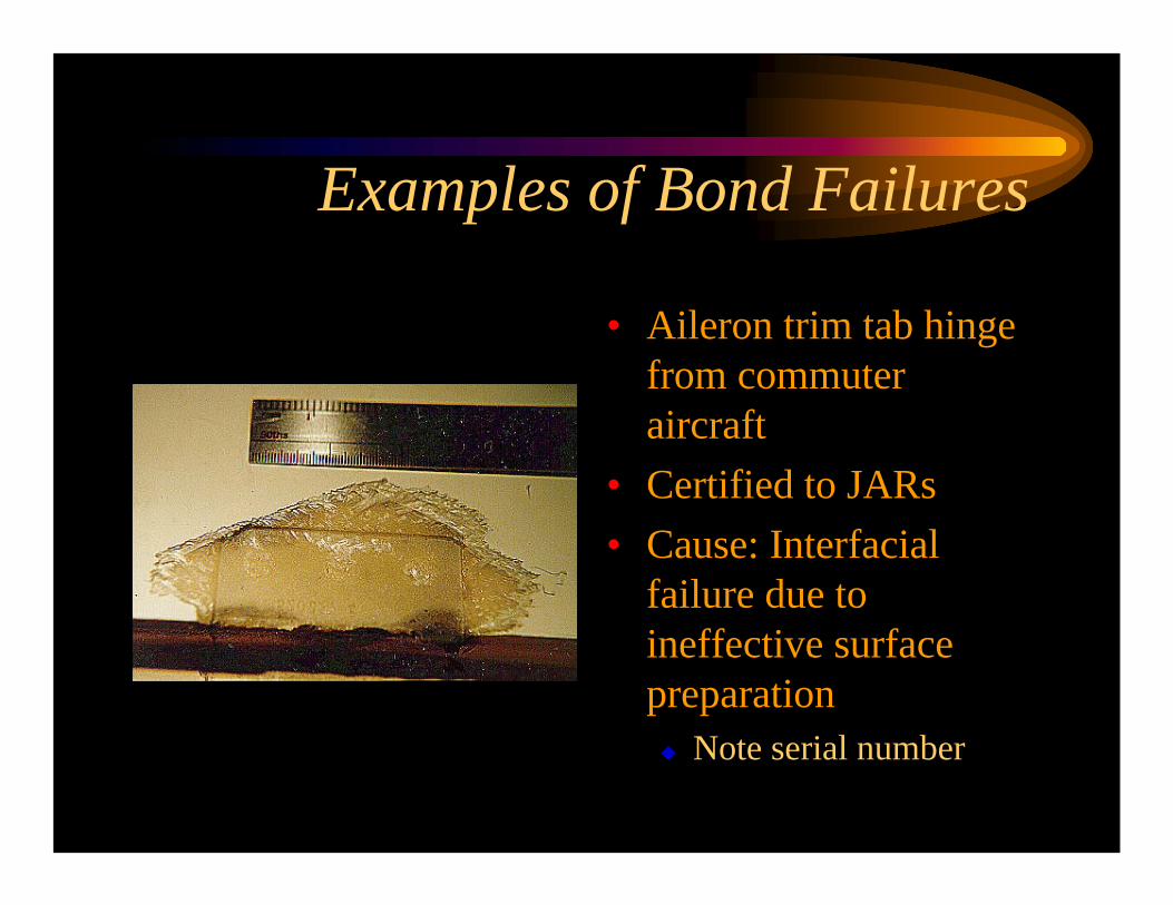
• Aileron trim tab hinge from commuter aircraft
• Certified to JARs• Cause: Interfacial
failure due to ineffective surface preparation
Note serial number

Composite Kit Aircraft Failure
• Not related to crash• Surface of main spar
at skin bond• No adhesive present• Adhesive scraped off
during fabrication• Pencil mark still
evident on bond surface. Preparation?
Adhesive
Sandwich Panel Failure
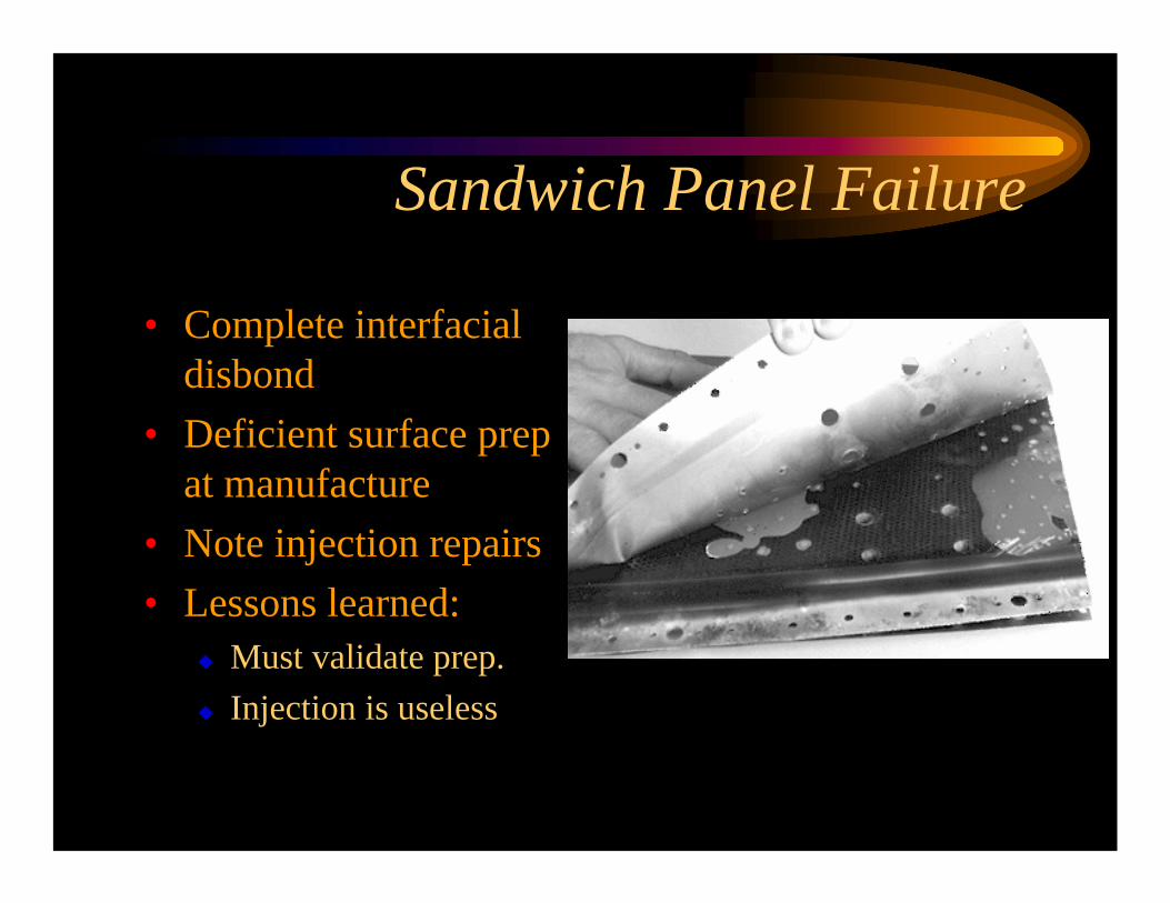
• Complete interfacial disbond
• Deficient surface prep at manufacture
• Note injection repairs• Lessons learned:
Must validate prep.Injection is useless

A Good Bond:F-111 Lower Wing Crack Repair
• Fatigue crack at fuel flow point under spar
• Critical crack• Bonded boron/epoxy • Validated FEM, sub-
component fatigue 30,000 hrs
Growth 48mm - 64mmFailed at 99% DUL
Wing withdrawn after 670 hrs, fatigued for 12000, unrelated failure

Composite Patch Failure
• Interfacial failure of repair to F/A-18
• Silicone coated peel ply used
• No instruction to remove peel ply in SRM

Boron Patch Failure
• Eight patches out of 180 failed in service
Seven applied in Malaysia in 1980
• Adhesive exhibited micro-voiding due to humidity during repair
• Remaining adhesive failed in fatigue
Lesson Learned:Environment must be controlled

Sandwich Panel Repair Failure
• F-111 external skin• Patch departed in flight• Causes:
Ineffective surface prep.Undercure of adhesive
• Lessons Learned:Use only valid processesCan’t use just one heater blanket on complex structure

Deficient Surface Preparation• Surface preparation is most significant
factor in long term bond durabilityCause of most bond failures in service
• Most failures caused by ineffective processes not just contamination
• Requires clean, chemically active surface that is resistant to hydration
A clean surface alone is not sufficient

Substantiation of Bond Durability• Lap shear tests per
ASTM D1002 inappropriate
• Test is adequate for Quality Assurance
• Lap shear will NOT validate long term bond durability
BondStrength
Time
Good Process
Bad Process
• Test early, all processes will pass• Inferior processes will fail in service

Substantiation of Processes• The key to metal bond durability is to validate
using the wedge test ASTM D3762
• Acceptance criteria must be more stringentBroad consensus:
• ∆a<0.20 in/24 hrs and 0.25 in/48 hrs • <5% adhesion failure
• Durable bonds meet these criteria
a
Pro and Con
• For:Service history shows:
• Lap shear testing is not discriminating between good and bad processes
• For metals, durable bonds meet wedge test criteria
• Against:Test is not representative of service loadsDatabase is anecdotal

Validation for Composite Bonds?
• Data on wedge tests for composite bonds is very limited but shows some promise
• Problems expected:Lay-up to be used Top ply failure may occur
• Is there a better test?????

Peel Plies
• Poor performance of some peel plies demonstrates the need for a validation test
• Silicone, Teflon coated plies DO transfer• Corona treated plies leave an inactive
glazed surface• RAAF experience: Always lightly grit blast

Quality Management• Close attention usually paid to quality control
testing to assure integrity• QC, NDT only identify extremely bad bonds
Does not provide assurance of a good bond• QC, NDT only of value if environmental
durability is validated before using the process• Best practice is to manage quality through
process, not just to measure it after bonding

Repair Bonding
• Requirements are the same as construction • The processes are different
Surface Preparation• Non tank, on-aircraft
Heating• Non-autoclave, usually heater blankets
Pressurisation• Non-autoclave, usually vacuum bag
• Materials must be suited to these processes
Heat Cured Repairs
• Risk of undercure of adhesive or overheat damage to structure
• Strongly influenced by heating methodology and temperature sensor usage

Dangers with Single Heat Sources
Overheat
Undercure
Patch Heater Blanket
Frame
Longeron
Thin skin

Heater Configuration
Patch
Frame
Longeron
Thin skin
Zone 1
Zone 2
Zone 3Zone 4

Temperature Sensor Installation• Temperature sensors used for two purposes:
To ensure structure is not overheatedTo provide assurance of full cure
• For control (overheating) On surface being heated within each heated zone where the HIGHEST temperature is anticipated
• For assurance of cure, on surface being heated within 12 mm of repair to measure LOWEST temperature around the bond line

Sensors Location• Sensors for assurance of cure• Sensors for control
Patch
Frame
Longeron
Thin skin

Design Issues
• Many OEMs design using an “allowable”average shear stress
Based on lap-shear data ASTM D1002Usually with “building block” approach
• Coupon, sub-component and component tests
• Designs can be unconservative• Ignores the real shear stress distribution that
occurs in bonded joints

Adhesive Load Capacity
• RAAF uses Hart-Smith’s bond load capacity to manage designs
• Methodology:Calculate load capacity, compare with load caseAssess requirement for a more rigorous designProvide enough overlap to achieve load capacity
⎟⎟⎠
⎞⎜⎜⎝
⎛+⎟
⎠⎞
⎜⎝⎛ +=
oo
iiiipep tE
tEtEP 12121 γγητ ⎟⎟
⎠
⎞⎜⎜⎝
⎛+⎟
⎠⎞
⎜⎝⎛ +=
ii
oooopep tE
tEtEP 12122 γγητ

Load Capacity Approach
• Possible to design bond stronger than parent material
• Adhesive will NEVER fail by shear
• Possible to reduce testing requirements
All specimens will fail outside bond
ShearAdherend
Adherend Thickness
Strength
Bond stronger Bond weaker
A B

RAAF use of Joint Condition• Condition 1:
Adhesive Load Capacity> 1.2 DUL• Joint should never fail in service• Testing should always fail structure away from joint
• Condition 2:Adhesive Load Capacity>DUL but <1.2DUL
• Joint should be adequate• Requires more rigorous design and testing
• Other conditions applicable only to fatigue enhancement or emergency repairs

Application of approach• Joint condition used in conjunction with
assessment of significance to determine level of design rigour
Primary or significant structure or Condition 2 requires validation by FE and/or testingSecondary or non-significant structure, then Condition 1 joint does not require validation or testing, simple design methods acceptable
Certification of Repairs
• Current USAF approach for repairs: 1.2DUL without the repair
• RAAF experience: valid designs, processes then bond NEVER fails
• Design should give credit for the repairRAAF proposes a Risk Based Analysis method

Design Data
• Database of adhesive properties is small and inaccurate
• Lap-shear, peel data are not suited to design• Need a shared repository for design data
(MIL HDBK 17?)

Fatigue Testing of Adhesives
• Lap shear ASTM D3165 is not a valid testShort overlap causes entire joint to be plasticNo creep recovery due to lack of elastic zone Adherend plastic behaviour near fatigue limit causes premature failure of adhesive
• Thick adherend ASTM D5656 not valid either
Entire joint becomes plastic, no creep recovery

Fatigue of Adhesives
• Real Joint: Adhesive can be fatigued past elastic limit without failure
• Conclusion: Fatigue tests should use realistic joints, not lap-shear specimens

Conclusions
• Substantiation of environmental durability is absolutely essential
Must be a rigorous test methodMust be part of certification basis
• Quality should be managed not measured• Repair processes and materials may be
different to construction

Conclusions
• Design on average shear is inappropriate• Need a certification basis to give credit for
repairs• Fatigue tests should use realistic joints

Managing Adhesive Bond Integrity
• FARs rely on a process specification, quality control and NDT
Process Specifications are useless unless properly validatedQC tests usually short term strength tests
• Does not test environmental durability
NDT only tells of bondline gaps
Recommendation
• Amend FAR Sec. 25.605• Fabrication methods.• [(a)] The methods of fabrication used must produce a consistently
sound and durable structure. If a fabrication process (such as gluing, spot welding, or heat treating) requires close control to reach this objective, the process must be performed under an approved process specification that has been demonstrated to produce a structure that is strong and durable.
• [(b) Each new aircraft fabrication method must be substantiated by a test program that demonstrates that the process used is capable of producing a structure that is strong and durable.]
• Will require limited additional testing