Embed Size (px)
Citation preview
1
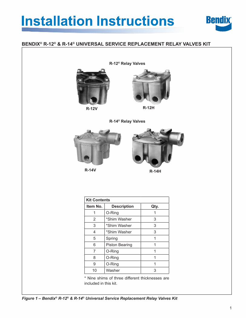
BENDIX® R-12® & R-14® UNIVERSAL SERVICE REPLACEMENT RELAY VALVES KIT
Figure 1 – Bendix® R-12® & R-14® Universal Service Replacement Relay Valves Kit
R-12® Relay Valves
R-14® Relay Valves
R-12V R-12H
R-14V R-14H
Kit ContentsItem No. Description Qty.
1 O-Ring 12 *Shim Washer 33 *Shim Washer 34 *Shim Washer 35 Spring 16 Piston Bearing 17 O-Ring 18 O-Ring 19 O-Ring 110 Washer 3
* Nine shims of three different thicknesses are included in this kit.
2
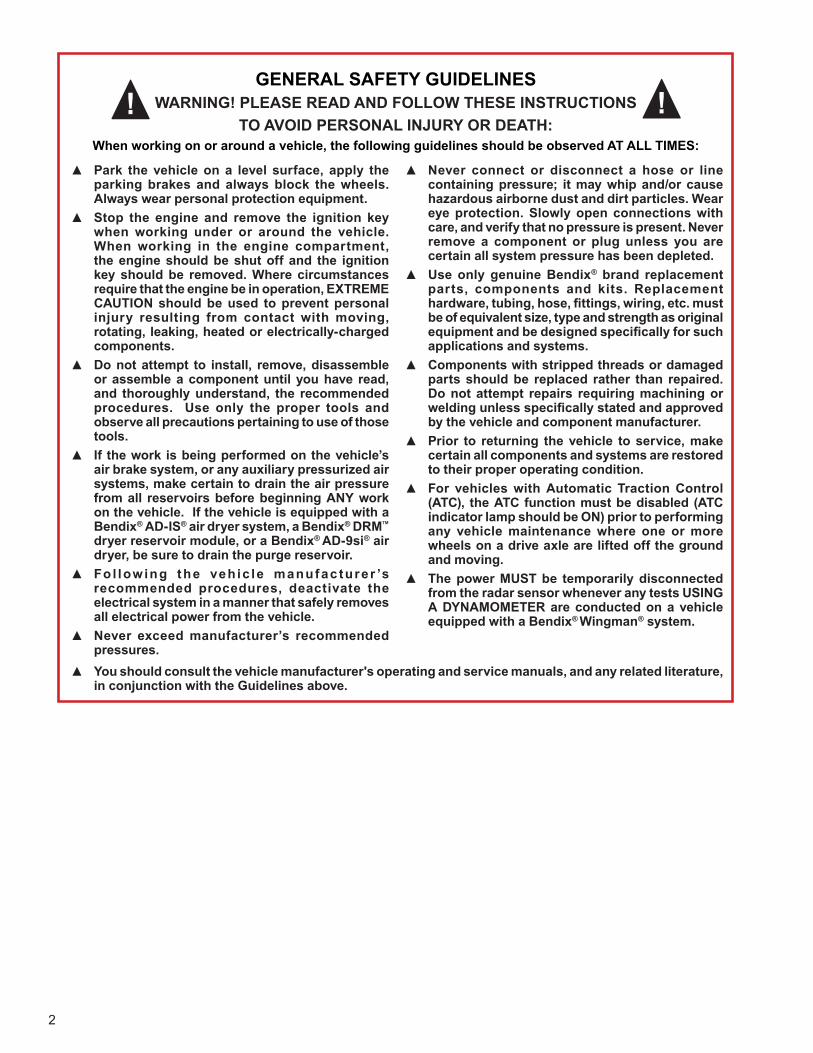
GENERAL SAFETY GUIDELINESWARNING! PLEASE READ AND FOLLOW THESE INSTRUCTIONS
TO AVOID PERSONAL INJURY OR DEATH:When working on or around a vehicle, the following guidelines should be observed AT ALL TIMES:
▲ Park the vehicle on a level surface, apply the parking brakes and always block the wheels. Always wear personal protection equipment.
▲ Stop the engine and remove the ignition key when working under or around the vehicle. When working in the engine compartment, the engine should be shut off and the ignition key should be removed. Where circumstances require that the engine be in operation, EXTREME CAUTION should be used to prevent personal injury resulting from contact with moving, rotating, leaking, heated or electrically-charged components.
▲ Do not attempt to install, remove, disassemble or assemble a component until you have read, and thoroughly understand, the recommended procedures. Use only the proper tools and observe all precautions pertaining to use of those tools.
▲ If the work is being performed on the vehicle’s air brake system, or any auxiliary pressurized air systems, make certain to drain the air pressure from all reservoirs before beginning ANY work on the vehicle. If the vehicle is equipped with a Bendix® AD-IS® air dryer system, a Bendix® DRM™ dryer reservoir module, or a Bendix® AD-9si® air dryer, be sure to drain the purge reservoir.
▲ Fo l lowing the vehic le manufac turer ’s recommended procedures, deactivate the electrical system in a manner that safely removes all electrical power from the vehicle.
▲ Never exceed manufacturer’s recommended pressures.
▲ Never connect or disconnect a hose or line containing pressure; it may whip and/or cause hazardous airborne dust and dirt particles. Wear eye protection. Slowly open connections with care, and verify that no pressure is present. Never remove a component or plug unless you are certain all system pressure has been depleted.
▲ Use only genuine Bendix® brand replacement parts, components and kits. Replacement hardware, tubing, hose, fi ttings, wiring, etc. must be of equivalent size, type and strength as original equipment and be designed specifi cally for such applications and systems.
▲ Components with stripped threads or damaged parts should be replaced rather than repaired. Do not attempt repairs requiring machining or welding unless specifi cally stated and approved by the vehicle and component manufacturer.
▲ Prior to returning the vehicle to service, make certain all components and systems are restored to their proper operating condition.
▲ For vehicles with Automatic Traction Control (ATC), the ATC function must be disabled (ATC indicator lamp should be ON) prior to performing any vehicle maintenance where one or more wheels on a drive axle are lifted off the ground and moving.
▲ The power MUST be temporarily disconnected from the radar sensor whenever any tests USING A DYNAMOMETER are conducted on a vehicle equipped with a Bendix® Wingman® system.
▲ You should consult the vehicle manufacturer's operating and service manuals, and any related literature, in conjunction with the Guidelines above.
3
Midland® KN28010, 28010A
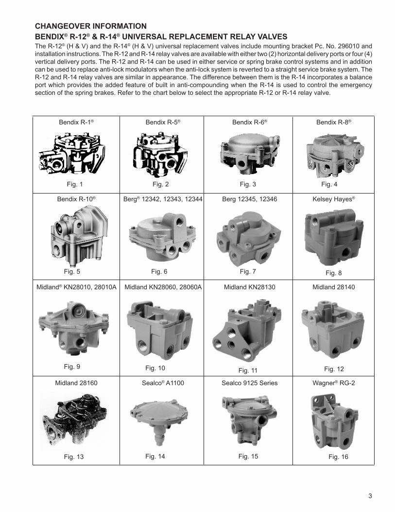
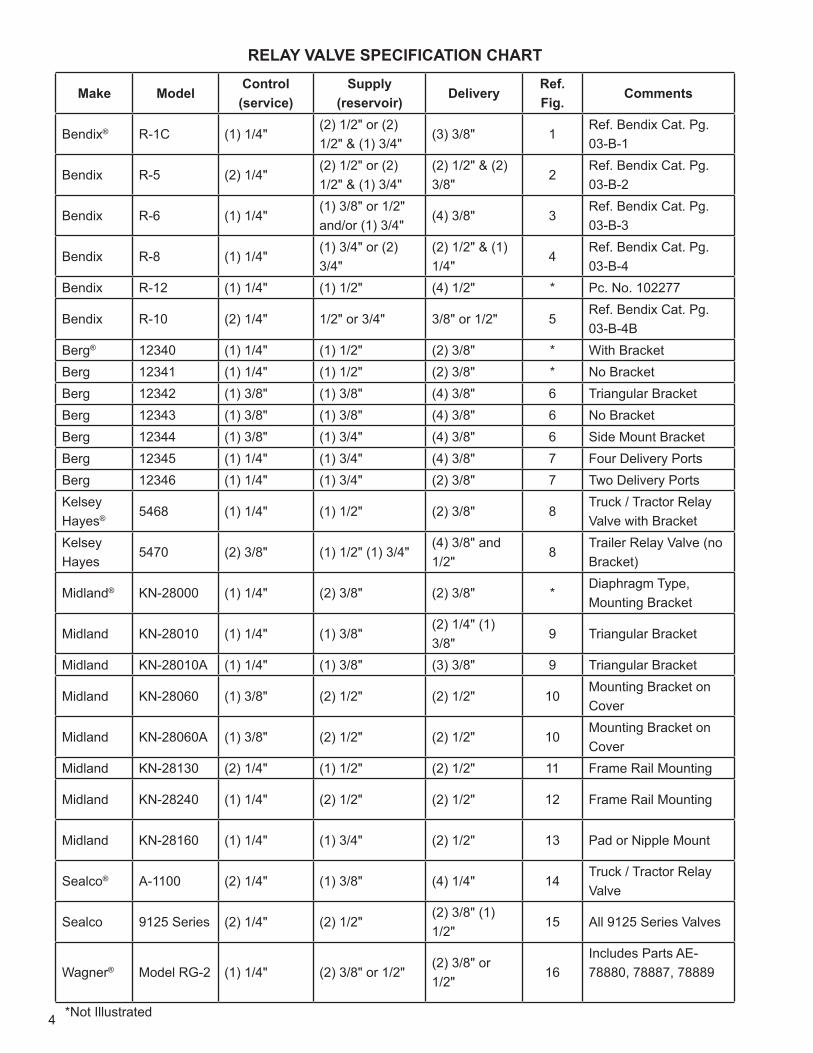
CHANGEOVER INFORMATIONBENDIX® R-12® & R-14® UNIVERSAL REPLACEMENT RELAY VALVESThe R-12® (H & V) and the R-14® (H & V) universal replacement valves include mounting bracket Pc. No. 296010 and installation instructions. The R-12 and R-14 relay valves are available with either two (2) horizontal delivery ports or four (4) vertical delivery ports. The R-12 and R-14 can be used in either service or spring brake control systems and in addition can be used to replace anti-lock modulators when the anti-lock system is reverted to a straight service brake system. The R-12 and R-14 relay valves are similar in appearance. The difference between them is the R-14 incorporates a balance port which provides the added feature of built in anti-compounding when the R-14 is used to control the emergency section of the spring brakes. Refer to the chart below to select the appropriate R-12 or R-14 relay valve.
Fig. 4
Fig. 5 Fig. 6 Fig. 7 Fig. 8
Fig. 9 Fig. 10
Fig. 1 Fig. 3Fig. 2
Fig. 11 Fig. 12
Fig. 13 Fig. 14 Fig. 15 Fig. 16
Bendix R-1® Bendix R-5® Bendix R-6® Bendix R-8®
Bendix R-10® Berg® 12342, 12343, 12344 Berg 12345, 12346 Kelsey Hayes®
Midland KN28060, 28060A Midland KN28130 Midland 28140
Midland 28160 Sealco® A1100 Sealco 9125 Series Wagner® RG-2
4
Make ModelControl
(service)Supply
(reservoir)Delivery
Ref. Fig.
Comments
Bendix® R-1C (1) 1/4"(2) 1/2" or (2) 1/2" & (1) 3/4"
(3) 3/8" 1Ref. Bendix Cat. Pg. 03-B-1
Bendix R-5 (2) 1/4"(2) 1/2" or (2) 1/2" & (1) 3/4"
(2) 1/2" & (2) 3/8"
2Ref. Bendix Cat. Pg. 03-B-2
Bendix R-6 (1) 1/4"(1) 3/8" or 1/2" and/or (1) 3/4"
(4) 3/8" 3Ref. Bendix Cat. Pg. 03-B-3
Bendix R-8 (1) 1/4"(1) 3/4" or (2) 3/4"
(2) 1/2" & (1) 1/4"
4Ref. Bendix Cat. Pg. 03-B-4
Bendix R-12 (1) 1/4" (1) 1/2" (4) 1/2" * Pc. No. 102277
Bendix R-10 (2) 1/4" 1/2" or 3/4" 3/8" or 1/2" 5Ref. Bendix Cat. Pg. 03-B-4B
Berg® 12340 (1) 1/4" (1) 1/2" (2) 3/8" * With BracketBerg 12341 (1) 1/4" (1) 1/2" (2) 3/8" * No BracketBerg 12342 (1) 3/8" (1) 3/8" (4) 3/8" 6 Triangular BracketBerg 12343 (1) 3/8" (1) 3/8" (4) 3/8" 6 No BracketBerg 12344 (1) 3/8" (1) 3/4" (4) 3/8" 6 Side Mount BracketBerg 12345 (1) 1/4" (1) 3/4" (4) 3/8" 7 Four Delivery PortsBerg 12346 (1) 1/4" (1) 3/4" (2) 3/8" 7 Two Delivery PortsKelsey Hayes® 5468 (1) 1/4" (1) 1/2" (2) 3/8" 8
Truck / Tractor Relay Valve with Bracket
Kelsey Hayes
5470 (2) 3/8" (1) 1/2" (1) 3/4"(4) 3/8" and 1/2"
8Trailer Relay Valve (no Bracket)
Midland® KN-28000 (1) 1/4" (2) 3/8" (2) 3/8" *Diaphragm Type, Mounting Bracket
Midland KN-28010 (1) 1/4" (1) 3/8"(2) 1/4" (1) 3/8"
9 Triangular Bracket
Midland KN-28010A (1) 1/4" (1) 3/8" (3) 3/8" 9 Triangular Bracket
Midland KN-28060 (1) 3/8" (2) 1/2" (2) 1/2" 10Mounting Bracket on Cover
Midland KN-28060A (1) 3/8" (2) 1/2" (2) 1/2" 10Mounting Bracket on Cover
Midland KN-28130 (2) 1/4" (1) 1/2" (2) 1/2" 11 Frame Rail Mounting
Midland KN-28240 (1) 1/4" (2) 1/2" (2) 1/2" 12 Frame Rail Mounting
Midland KN-28160 (1) 1/4" (1) 3/4" (2) 1/2" 13 Pad or Nipple Mount
Sealco® A-1100 (2) 1/4" (1) 3/8" (4) 1/4" 14Truck / Tractor Relay Valve
Sealco 9125 Series (2) 1/4" (2) 1/2"(2) 3/8" (1) 1/2"
15 All 9125 Series Valves
Wagner® Model RG-2 (1) 1/4" (2) 3/8" or 1/2"(2) 3/8" or 1/2"
16Includes Parts AE-78880, 78887, 78889
*Not Illustrated
RELAY VALVE SPECIFICATION CHART
5
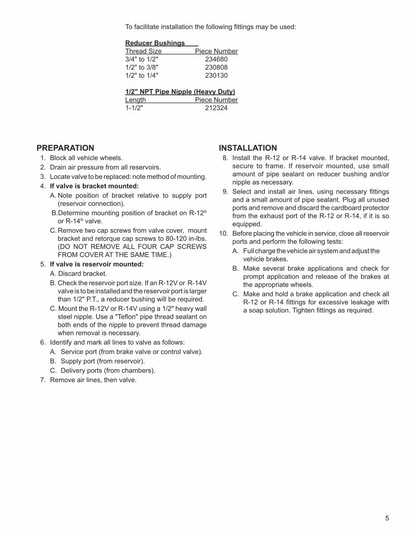
To facilitate installation the following fittings may be used:
Reducer Bushings Thread Size Piece Number3/4" to 1/2" 2346801/2" to 3/8" 230808 1/2" to 1/4" 230130
1/2" NPT Pipe Nipple (Heavy Duty) Length Piece Number1-1/2" 212324
PREPARATION 1. Block all vehicle wheels. 2. Drain air pressure from all reservoirs. 3. Locate valve to be replaced: note method of mounting. 4. If valve is bracket mounted:
A. Note position of bracket relative to supply port (reservoir connection).
B.Determine mounting position of bracket on R-12®
or R-14® valve. C. Remove two cap screws from valve cover, mount
bracket and retorque cap screws to 80-120 in-lbs. (DO NOT REMOVE ALL FOUR CAP SCREWS FROM COVER AT THE SAME TIME.)
5. If valve is reservoir mounted: A. Discard bracket. B. Check the reservoir port size. If an R-12V or R-14V
valve is to be installed and the reservoir port is larger than 1/2" P.T., a reducer bushing will be required.
C. Mount the R-12V or R-14V using a 1/2" heavy wall steel nipple. Use a "Teflon" pipe thread sealant on both ends of the nipple to prevent thread damage when removal is necessary.
6. Identify and mark all lines to valve as follows: A. Service port (from brake valve or control valve). B. Supply port (from reservoir). C. Delivery ports (from chambers).
7. Remove air lines, then valve.
INSTALLATION 8. Install the R-12 or R-14 valve. If bracket mounted,
secure to frame. If reservoir mounted, use small amount of pipe sealant on reducer bushing and/or nipple as necessary.
9. Select and install air lines, using necessary fittings and a small amount of pipe sealant. Plug all unused ports and remove and discard the cardboard protector from the exhaust port of the R-12 or R-14, if it is so equipped.
10. Before placing the vehicle in service, close all reservoir ports and perform the following tests:
A. Full charge the vehicle air system and adjust the vehicle brakes.
B. Make several brake applications and check for prompt application and release of the brakes at the appropriate wheels.
C. Make and hold a brake application and check all R-12 or R-14 fittings for excessive leakage with a soap solution. Tighten fittings as required.

6S-0758 Rev. 002 © 2019 Bendix Commercial Vehicle Systems LLC, a member of the Knorr-Bremse Group • 12/19 • All Rights Reserved
Log-on and Learn from the BestOn-line training that's available when you are 24/7/365.
Visit brake-school.com.