Embed Size (px)
Citation preview

Bending for MMAE and CAE students
Academic Resource Center

Topics Covered
1) General analysis of forces in beams
2) Determination of stresses in beams
1) Compressive and tensile stresses
2) Shear stresses
3) Bending of composite materials
4) Notes on design
5) Questions/practice problems
Analysis of Forces in Beams
Notes:
• w(x), V(x), M(x) may not be linear (point loads)
• If non linear, evaluate integral at discontinuities
• M.0, V.0 are “initial value” of function at x.i=0 of evaluation
• X.i is “x axis” for a continuous function on the beam
W(x) is distributed load with units
“force/length”

Analysis of Forces in Beams
Notes:
• Notice zones x.1, x.2, x.3 at changes in loading
• Notice functions of V and M for each different zone
• Reactions R.A and R.B are solved from equilibrium at start of problem
Determination of Stresses in Beams
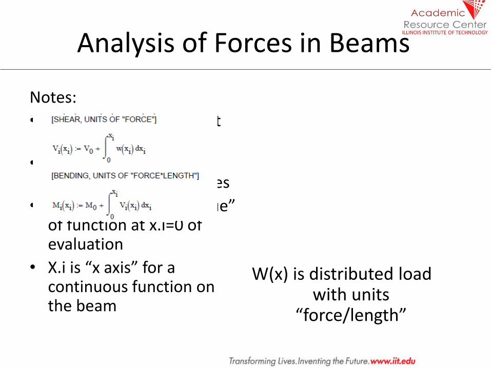
• Based on assumptions:
– Planes remain plane and normal
– Small, linear deformations
– Stresses within elastic range of materials (therefore governed by Hooke’s Law)
• Second assumption is checked by:

Determination of Stresses in Beams
Notes: • “y” is taken from neutral
axis – This convention will make
points at the bottom of the beam “-y” negative, which indicates tension and vice versa for compression
• “I” is relative to neutral axis – Utilize parallel axis theorem
shown in equation 3!!! • Equation 1 applies for all
cross sections • Equation 2 applies for
prismatic (rectangular) cross sections
Determination of Stresses in Beams
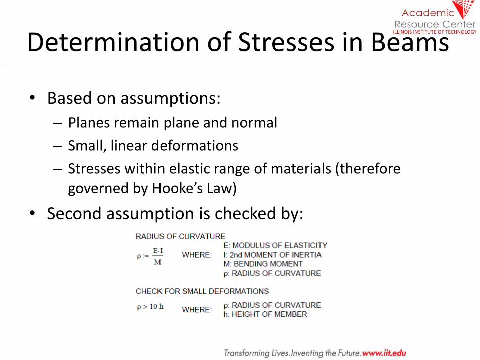
Maximum Axial Stress • “c” is the position of the
centroid relative to the top or bottom of the member
• From previous relationship, if y=c, stress is evaluated at a maximum point

Determination of Stresses in Beams
Vertical Shear Stress • A shear force “V” causes a
non uniform distribution of shear stress on a member’s cross section
• Approximations to the right apply ONLY for rectangular cross sections
Determination of Stresses in Beams
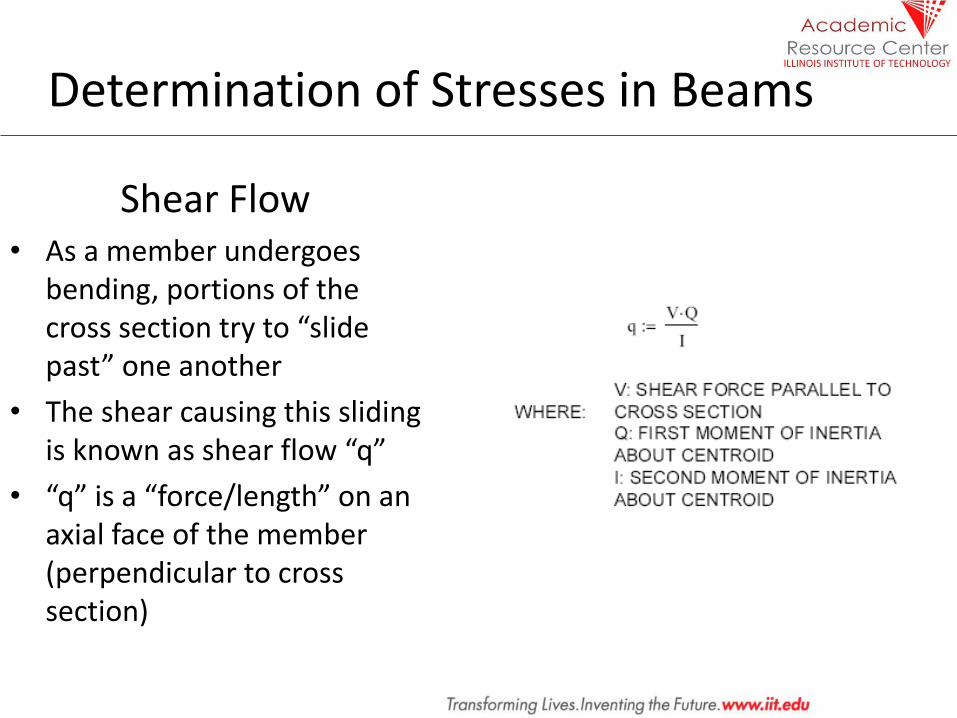
Shear Flow • As a member undergoes
bending, portions of the cross section try to “slide past” one another
• The shear causing this sliding is known as shear flow “q”
• “q” is a “force/length” on an axial face of the member (perpendicular to cross section)
Bending of Composite Members
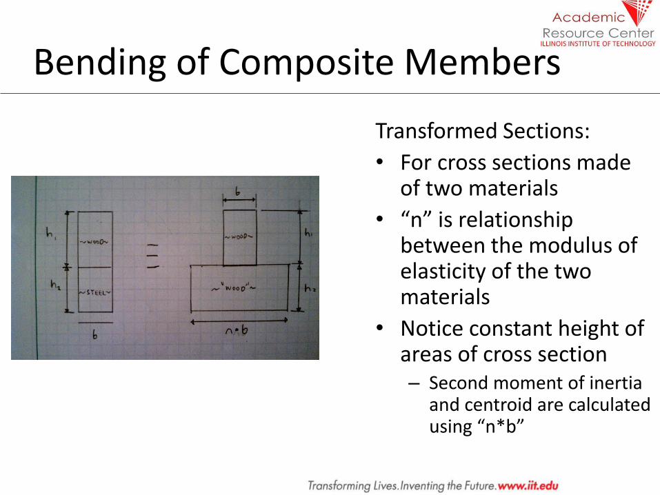
Transformed Sections:
• For cross sections made of two materials
• “n” is relationship between the modulus of elasticity of the two materials
• Notice constant height of areas of cross section – Second moment of inertia
and centroid are calculated using “n*b”
Notes on Design
1. Start by determining shear and bending moment diagrams!
• Do not forget the member’s self weight (which becomes a distributed load)
• It is advantageous to separate different loading types and develop a shear and bending moment diagram for each (different “load factors” apply in design)
2. “S” the section modulus of a member is a commonly available property in documents such as the American Institute of Steel Construction’s Steel Manual
3. The maximum allowable stress of a material is a commonly available property for steel, concrete, etc.

Practice Problems
1. 5.76 page 339 of reference [analysis for shear and bending]
2. 4.9 page 225 of reference [analysis for shear and bending, determination of axial stresses]
3. 6.1 page 384 of reference [determination and usage of shear flow]
4. 6.5 page 386 of reference [analysis for shear and bending, design of maximum shear and axial stresses]
5. 4.50 page 240 of reference [stresses in composite cross sections]
References
Beer, Ferdinand et. al. Mechanics of Materials, 4TH Edition. 2006. McGraw Hill.