Embed Size (px)
Citation preview

BELT DRIVE PREVENTIVE MAINTENANCE AND SAFETY MANUAL
www.gates.com/drivedesign

TABLE OF CONTENTS
Safety Policy . . . . . . . . . . . . . . . . . . . . . . . . . . . . . . . . . . . . . . . . . . . . . . . . . . . . . . . . . . . . . . . .1Sources of Drive Problems . . . . . . . . . . . . . . . . . . . . . . . . . . . . . . . . . . . . . . . . . . . . . . . . . . . . .2Preventive Maintenance . . . . . . . . . . . . . . . . . . . . . . . . . . . . . . . . . . . . . . . . . . . . . . . . . . . . . . .3Safety . . . . . . . . . . . . . . . . . . . . . . . . . . . . . . . . . . . . . . . . . . . . . . . . . . . . . . . . . . . . . . . . . . . . . .4Drive Shutdown & Thorough Inspection Simple Inspection . . . . . . . . . . . . . . . . . . . . . . . . . . . . . . . . . . . . . . . . . . . . . . . . . . . . . . . . . . .5 Preventive Maintenance Checklist . . . . . . . . . . . . . . . . . . . . . . . . . . . . . . . . . . . . . . . . . . . . . . .6 Preventive Maintenance Procedure . . . . . . . . . . . . . . . . . . . . . . . . . . . . . . . . . . . . . . . . . . . . . .7 Measuring Belt Tension . . . . . . . . . . . . . . . . . . . . . . . . . . . . . . . . . . . . . . . . . . . . . . . . . . . . . . .8Installation . . . . . . . . . . . . . . . . . . . . . . . . . . . . . . . . . . . . . . . . . . . . . . . . . . . . . . . . . . . . . . . . .14Belt Storage & Handling . . . . . . . . . . . . . . . . . . . . . . . . . . . . . . . . . . . . . . . . . . . . . . . . . . . . . .18Belt Identification . . . . . . . . . . . . . . . . . . . . . . . . . . . . . . . . . . . . . . . . . . . . . . . . . . . . . . . . . . .20Belt Types . . . . . . . . . . . . . . . . . . . . . . . . . . . . . . . . . . . . . . . . . . . . . . . . . . . . . . . . . . . . . . . . . .25Belt Styles . . . . . . . . . . . . . . . . . . . . . . . . . . . . . . . . . . . . . . . . . . . . . . . . . . . . . . . . . . . . . . . . .28Static Conductive Belts . . . . . . . . . . . . . . . . . . . . . . . . . . . . . . . . . . . . . . . . . . . . . . . . . . . . . .30Belt Drive Performance . . . . . . . . . . . . . . . . . . . . . . . . . . . . . . . . . . . . . . . . . . . . . . . . . . . . . . .31Noise . . . . . . . . . . . . . . . . . . . . . . . . . . . . . . . . . . . . . . . . . . . . . . . . . . . . . . . . . . . . . . . . . . . . . .33Sprocket Corrosion Prevention . . . . . . . . . . . . . . . . . . . . . . . . . . . . . . . . . . . . . . . . . . . . . . . .35Troubleshooting Guide . . . . . . . . . . . . . . . . . . . . . . . . . . . . . . . . . . . . . . . . . . . . . . . . . . . . . . .37Problem/Solution Summary Table . . . . . . . . . . . . . . . . . . . . . . . . . . . . . . . . . . . . . . . . . . . . . .39Maintenance Tools . . . . . . . . . . . . . . . . . . . . . . . . . . . . . . . . . . . . . . . . . . . . . . . . . . . . . . . . . . .48Technical Information . . . . . . . . . . . . . . . . . . . . . . . . . . . . . . . . . . . . . . . . . . . . . . . . . . . . . . . .51 NEMA Minimum Diameters . . . . . . . . . . . . . . . . . . . . . . . . . . . . . . . . . . . . . . . . . . . . . . . . . . .52 Minimum Recommended Diameters . . . . . . . . . . . . . . . . . . . . . . . . . . . . . . . . . . . . . . . . . . . .54 Installation & Tensioning Allowances . . . . . . . . . . . . . . . . . . . . . . . . . . . . . . . . . . . . . . . . . . . .56Idler Hardware . . . . . . . . . . . . . . . . . . . . . . . . . . . . . . . . . . . . . . . . . . . . . . . . . . . . . . . . . . . . . .60Drive Survey Worksheet High Speed . . . . . . . . . . . . . . . . . . . . . . . . . . . . . . . . . . . . . . . . . . . . . . . . . . . . . . . . . . . . . . .63 Low Speed . . . . . . . . . . . . . . . . . . . . . . . . . . . . . . . . . . . . . . . . . . . . . . . . . . . . . . . . . . . . . . .64 Design IQ . . . . . . . . . . . . . . . . . . . . . . . . . . . . . . . . . . . . . . . . . . . . . . . . . . . . . . . . . . . . . . . .65Trademarks & Warranty . . . . . . . . . . . . . . . . . . . . . . . . . . . . . . . . . . . . . . . . . . . . . . . . . . . . . .66
Copyright 2013Gates CorporationDenver, Colorado 80217-5887
1
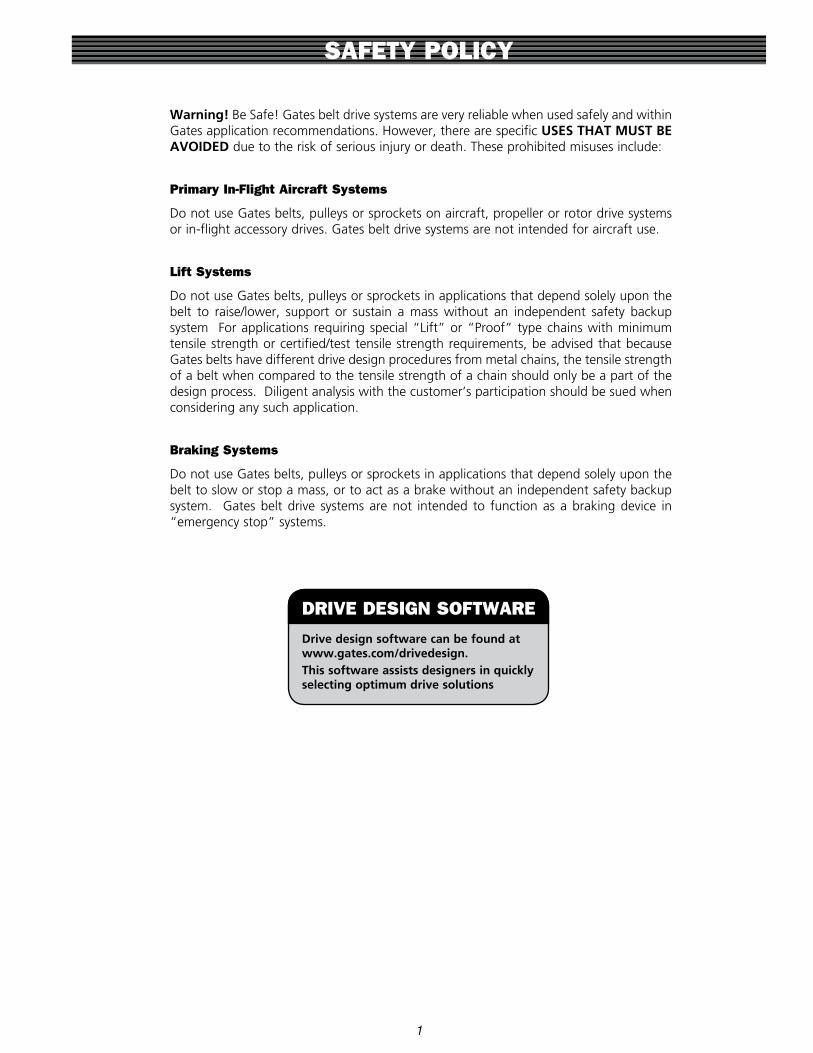
Warning! Be Safe! Gates belt drive systems are very reliable when used safely and within Gates application recommendations . However, there are specific USES THAT MUST BE AVOIDED due to the risk of serious injury or death . These prohibited misuses include:
Primary In-Flight Aircraft Systems
Do not use Gates belts, pulleys or sprockets on aircraft, propeller or rotor drive systems or in-flight accessory drives . Gates belt drive systems are not intended for aircraft use .
Lift Systems
Do not use Gates belts, pulleys or sprockets in applications that depend solely upon the belt to raise/lower, support or sustain a mass without an independent safety backup system For applications requiring special “Lift” or “Proof” type chains with minimum tensile strength or certified/test tensile strength requirements, be advised that because Gates belts have different drive design procedures from metal chains, the tensile strength of a belt when compared to the tensile strength of a chain should only be a part of the design process . Diligent analysis with the customer’s participation should be sued when considering any such application .
Braking Systems
Do not use Gates belts, pulleys or sprockets in applications that depend solely upon the belt to slow or stop a mass, or to act as a brake without an independent safety backup system . Gates belt drive systems are not intended to function as a braking device in “emergency stop” systems .
SAFETY POLICY
Drive design software can be found at www.gates.com/drivedesign.This software assists designers in quickly selecting optimum drive solutions
DRIVE DESIGN SOFTWARE

2
SOURCES OF DRIVE PROBLEMS
Improper Belt or Pulley Installation
Environmental Factors
Poor Drive Design
Improper Belt Storage or Handling
Defective Drive Components
Improper Drive Maintenance

Why have a preventive maintenance program?
When compared to the constant lubrication problems associated with chain drives, or the mechanical problems and high costs associated with gear drives, belts are the most cost-effective, reliable means of power transmission .However, optimum belt drive performance requires proper maintenance . The potential for long service life is built into every Gates belt . When coupled with a regularly scheduled maintenance program, belt drives will run rela-tively trouble-free for a long time .
Important to your business
An effective preventive maintenance program saves time and money . Inspecting and replacing belts and faulty drive components before they fail will reduce costly downtime and production delays .
What is a good belt maintenance program?
A comprehensive, effective program of preventive mainte-nance consists of several elements:
• Maintaining a safe working environment .
• Regularly scheduled belt drive inspections .• Proper belt installation
procedures .• Belt drive performance
evaluations .• Belt product knowledge .• Belt storage and handling .• Troubleshooting .
PREVENTIVE MAINTENANCE
Belt drive should have adequate guard
Carefully inspect all belts
* Note - If belt looks bad, it probably is
3
Power should be shut off and controls locked before inspecting

Maintaining A Safe Working Environment
It is common sense to establish a safe working environment in and around belt drives . The following precautions will make belt drive inspection and maintenance easier and safer .
Wear Proper Clothing
Never wear loose or bulky clothes, such as neckties, exposed shirttails, loose sleeves or loose lab coats around belt drives . Remove jewelry and tie up or restrain long hair . Wear gloves while inspecting sheaves or sprockets to avoid being cut by nicks, burrs or sharply worn pulley edges . Wear safety glasses to avoid eye injuries . Don’t be foolish! Wear proper clothing . Always wear proper personal protective equipment, including gloves, eye & ear protection, steel toe shoes, and a hard hat .
Maintain Safe Access to Drives
Always maintain safe access to the belt drives . Keep area around drives free of clutter, debris and other obstructions . Floors should be clean and free of oil and debris to insure good footing and balance while working on machinery .
Drive Guards
Always keep drives properly guarded . Every belt drive must be guarded when in operation . Guard must be designed and installed according to OSHA standards .
A Properly Guarded Belt Drive
A properly designed guard has the following features:
• Completely encloses drive .• Grills or vents for good ventilation .• Accessible inspection door or panels .• Can easily be removed and replaced if damaged .• Where necessary, should protect the drive from
weather, debris and damage .
Follow these precautions to make your preventive maintenance easier.
SAFETY
4
A properly guarded belt drive
Don’t clutter area around belt drive
No loose or bulky clothing. This technician’s bulky lab coat is a hazard near moving components
Power should be shut off and controls locked before inspecting

Simple Drive Inspection
Begin preventive maintenance with a periodic drive inspec-tion as a normal part of your maintenance rounds . Look and listen for any unusual vibration or sound while observing the guarded drive in operation . A well designed and maintained drive will operate smoothly and quietly .
Inspect guard for looseness or damage . Keep it free of debris or dust and grime buildup on either the inside or the outside of the guard . Any accumulation of material on the guard acts as insulation, and could cause drives to run hot-ter .
The effect of temperature on belt life is important . For example, an internal temperature increase of 18°F (or approximately 36°F rise in ambient drive temperature) may cut belt life in half . Beware of hot surfaces and the potential for injury .
Also look for oil or grease dripping from guard . This may indicate over-lubricated bearings . If this material gets on rubber belts, they may swell and become distorted, leading to early belt failure .
It’s a good idea to check motor mounts for proper tightness . Check take-up slots or rails to see that they are clean and lightly lubricated .
How Often To Inspect
The following factors influence how often to inspect a drive .
• Critical nature of equipment• Drive operating cycle• Accessibility of equipment• Drive operating speed• Environmental factors• Temperature extremes in environment
Experience with specific equipment is the best guide to how often to inspect belt drives . Drives operating at high speeds, heavy loads, frequent stop/start conditions and at tempera-ture extremes or operating on critical equipment require frequent inspection .
When To Perform Preventive Maintenance
To help establish a preventive maintenance schedule, keep the following in mind .
Critical Drives
A quick visual and noise inspection may be needed every one to two weeks .
Normal Drives
With most drives, a quick visual and noise inspection can be performed once a month .
Complete Inspection
A drive shutdown for a thorough inspection of belts, sheaves or sprockets and other drive components may be required every three to six months .
Remember, a well-designed industrial belt drive is capable of operating for several years when properly maintained and used under normal conditions .
Follow the Preventive Maintenance Procedure on the fol-lowing page when performing detailed maintenance during equipment shutdowns .
DRIVE SHUTDOWN & THOROUGH INSPECTION
5

DRIVE SHUTDOWN & THOROUGH INSPECTION
6
Preventive Maintenance Check List
By following these steps, belt drives can be maintained efficiently and safely .
1. Always turn off the power to the drive . Lock the con-trol box and tag it with a warning sign “Down For Maintenance . Do Not Turn Power On .” Make sure the power is turned off for the correct drive. Never have contact with a belt drive unless the system is tagged and locked out.
2. Test to make sure correct circuit has been turned off .
3. Place all machine components in a safe (neutral) position . Make sure that moving components are locked down or are in a safe position . Make sure that fans cannot unexpectedly freewheel .
4. Beware of pinch points . Keep hands and fingers clear, especially where belts enter sheaves and sprockets .
5. Remove guard and inspect for damage . Check for signs of wear or rubbing against drive components . Clean and realign guard to prevent rubbing if neces-sary .
6. Inspect belt for wear or damage . Replace as needed .
7. Inspect sheaves or sprockets for wear and misalign-ment . Replace if worn .
8. Inspect other drive components such as bearings, shafts, motor mounts and take-up rails .
9. Inspect static conductive grounding system (if used) and replace components as needed .
10. Check belt tension and adjust as needed .
11. Recheck sheave or sprocket alignment .
12. Reinstall belt guard .
13. Turn power back on and restart drive . Look and lis-ten for anything unusual .
Turn off power, lock controls and tag

DRIVE SHUTDOWN & THOROUGH INSPECTION
7
Preventive Maintenance Procedure
Once the power is off, locked and tagged, and the machine components are in safe positions, remove the guard and begin the inspection .
How to Inspect a Belt
Observing signs of unusual belt wear or damage will help troubleshoot possible drive problems .
Mark or note a point on the belt, or on one of the belts in a multiple V-belt drive . Wearing gloves, work around the belt(s), checking for cracks, frayed spots, cuts, or unusual wear patterns . Beware of pinch points . Keep hands and fingers clear, especially where belts enter sheaves and sprockets .
Check the belt for exposure to excessive heat . Excessive heat can come from a hot environment or from belt slip that generates heat . A typical maximum environmental tempera-ture for a properly maintained V-belt is 160˚F to 180˚F . The maximum environmental temperature for a properly main-tained synchronous belt is 185˚F .
Rubber belts that are running hot, or running in a hot envi-ronment will harden and develop cracks from the bottom of the belt upwards .
Refer to the PROBLEM/SOLUTION SUMMARY TABLE for other symptoms .
Belts should be replaced if there are obvious signs of crack-ing, fraying, unusual wear or loss of teeth .
How to Check Alignment
While the drive is shut down, it is a good idea to check the sheaves or sprockets for proper alignment .
To check alignment, use a straight edge, string, or Gates EZ Align™ laser alignment tool .
If using a straight edge (or string), line the straight edge along the outside face of both sheaves or sprockets as shown in the photo . If the drive is properly aligned, the straight edge or string will contact each sheave or sprocket evenly . The straight edge or string (pulled tight) should touch the two outer edges of each sheave or pulley for a total of four points of contact . Misalignment of sprockets and shafts will show up as a gap between the outside face of the sheave or sprocket and the straight edge . Check for tilting or shaft misalignment by using a bubble level . For proper alignment, the bubble should be in the same position as measured on each shaft .
Begin by inspecting the belt
Using a straight edge to check alignment
Using a string to check alignment
Using EZ Align® laser alignment tool on both ends
Using EZ Align® laser alignment tool, showing reflected laser on emitter
Using EZ Align® laser alignment tool showing laser line on target

DRIVE SHUTDOWN & THOROUGH INSPECTION
8
If using the Gates EZ Align® laser alignment tool, follow the detailed instructions included with the tool . The EZ Align laser alignment tool makes it very quick and easy to check alignment of shafts, sheaves and sprockets . EZ Align is avail-able with a red laser, or a green laser for outdoor or brighter environment use .
There are three possible causes and solutions of sheave or sprocket misalignment:
1 . Angular Misalignment: The motor shafts and driven machine shafts are not parallel .
a . Correct alignment by adjusting the motor shaft into alignment with the driveN shaft .
2 . Parallel Misalignment: Sheaves or sprockets are not properly located on the shafts .
a . Loosen and reposition one or both sheaves or sprockets until properly aligned .
3 . Sheaves or sprockets are tilted on the shaft due to incorrect bushing installation .
a . Rotate drive by hand and look for excessive wobble . Beware of pinch points . Keep hands and fingers clear, especially where belts enter sheaves and sprockets . If wobble is observed, remove and reinstall sheave or sprocket . Follow the bushing installation procedures explained in the INSTALLATION section . Further check alignment by using one of the previously mentioned methods .
Misalignment on V-belt drives should be less than 1/2˚ or 1/10” per foot of center distance . Misalignment for synchro-nous, Polyflex®, or Micro-V® belts should be less than 1/4˚ or 1/16” per foot of center distance .
When a synchronous belt drive has been aligned (follow-ing the procedure discussed above in the “How to Check Alignment” section), do not continue to adjust alignment in an attempt to make the synchronous belt ride in the cen-ter of the sprocket’s face width . Synchronous belts, while neutral tracking, will tend to ride in contact with a flange on one side of the sprockets . Synchronous belts on drives that are properly aligned will lightly contact the flanges . Synchronous belts on misaligned drives will ride hard against the flanges and generate additional noise . Attempting to adjust a synchronous belt drive’s alignment to force the belt to ride in the center of the sprocket’s face width will typi-cally result in misalignment .
Guard Inspection
Check the guard for wear or possible damage . Don’t over-look wear on the inside of the guard . Check for any areas that may be contacting the belt . Clean the guard to prevent it from becoming blocked and closed to ventilation . Clean off any grease or oil that may have spilled onto the guard from over-lubricated bearings .
Check Other Drive Components
It is always a good idea to examine bearings for proper lubri-cation . Check the motor base bolts and adjustment screws to make sure they are not loose . If loose, tighten to the rec-ommended torque value . Make sure that adjustment screws are free of debris, dirt, or rust .
Check Belt Tension
Following the drive component inspection, the final step is to check belt tension . Rotate the drive two or three revolu-tions by hand and check the belt tension . If necessary, reten-sion the belt and make a final alignment check .
If V-belts are undertensioned, they can slip . Slippage gener-ates heat and will result in cracking and belt failure .
If synchronous belts are undertensioned, they can jump teeth or ratchet . Ratcheting will damage the belt and result in premature belt failure .
If belts are overtensioned, belt and bearing life can be reduced .
The proper way to check belt tension is to use a tension tester . Gates has a variety of tension testers, ranging from the simple spring scale type tester to the sophisticated Sonic Tension Meter .

DRIVE SHUTDOWN & THOROUGH INSPECTION
9
Measuring Belt Tension
The spring scale type tester measures how much force is required to deflect the belt a specified distance at the center of its span . This is the force deflection method of tensioning belts .
The Sonic Tension Meter measures the vibration of the belt span and instantly converts the vibration frequency into belt static tension . This is the span vibration method of tension-ing belts .
For more information, refer to the Troubleshooting Tools section .
Force Deflection Tension Method
The force deflection tension method does not directly measure belt span tension or static tension . The deflection force is a calculated value that is based on the amount of static tension required in the belt . Static tension is the ten-sion force that is actually in the belt, while deflection force is simply a measurement to check how much static tension is in the belt . The tension testers used for the force deflec-tion tension method are available in one, two, or five barrel configurations . The one barrel tension tester can measure up to 30 lb . of force; the two barrel tension tester can measure up to 66 lb . of force; and the five barrel tension tester can measure up to 165 lb . of force . Add the force readings from each barrel to determine the total force being measured .
1 . Measure span length (t) . Span length is the distance from where the belt exits one pulley to where it enters the next pulley .
2 . Position the lower of the two O-Rings using either of these methods:
a . On the scale reading “Deflection Inches”, set the O-Ring to show a deflection equal to 1/64” per inch of span length (t) .
b . On the scale reading “Inches of Span Length”, set O-Ring to show a deflection equal to the inches of measured span length (t) .
3 . At the center of the span (t), apply force using the appro-priately sized Gates tension testers . Apply the force per-pendicular to the span . If the belt is a wide synchronous belt or a PowerBand belt, place a piece of steel or angle iron across the belt width and deflect the entire width of the belt evenly . Deflect the belt until the bottom edge of the lower O-Ring is at the correct deflection distance . If multiple individual V-belts are used on the drive, the deflection distance can be measured against an adjacent belt . For drives with only one belt, use a straightedge or string pulled tight across the sheaves, sprockets, or top of the belt to establish a reference line . When the belt is deflected to measure tension, measure the deflection dis-tance by measuring from the belt to the straight edge or string reference line .
Deflection1/64” per inchof span
Force
Span Length, t
DRIVE SHUTDOWN & THOROUGH INSPECTION
10
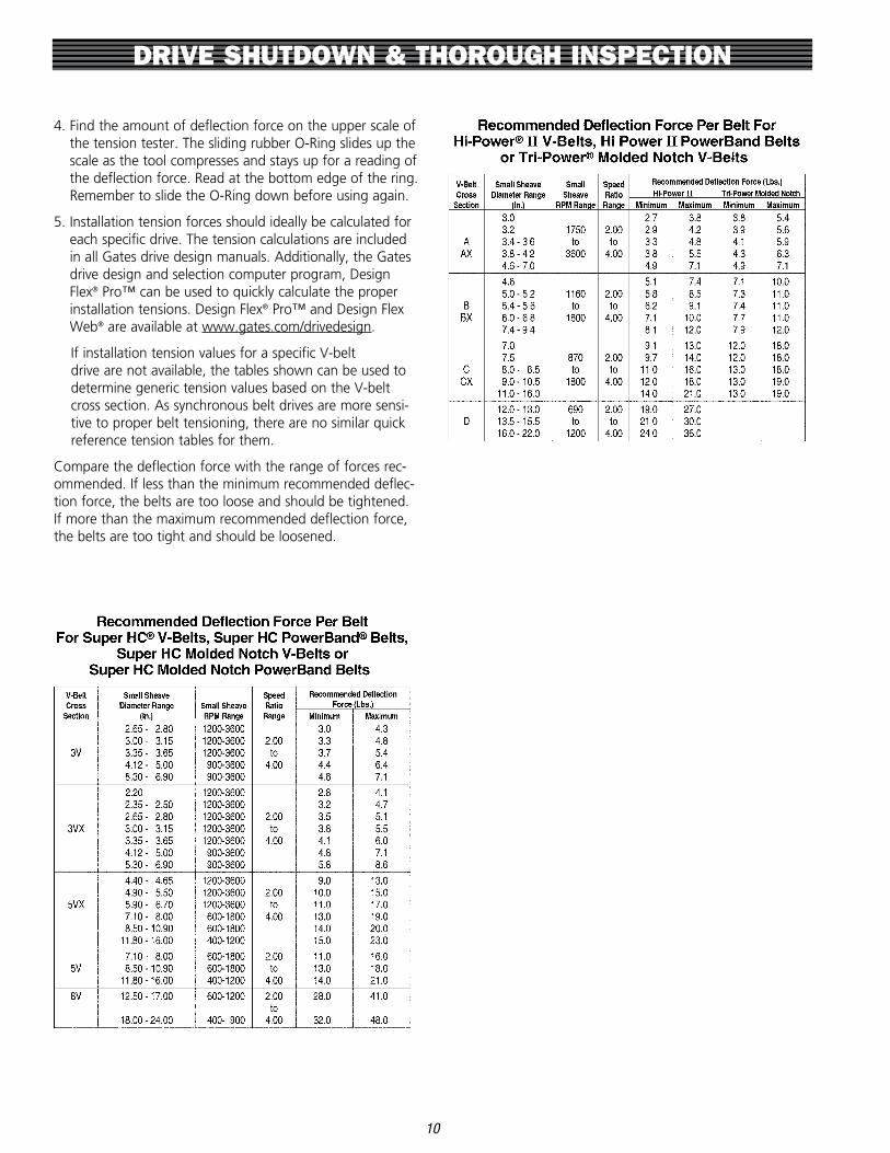
4 . Find the amount of deflection force on the upper scale of the tension tester . The sliding rubber O-Ring slides up the scale as the tool compresses and stays up for a reading of the deflection force . Read at the bottom edge of the ring . Remember to slide the O-Ring down before using again .
5 . Installation tension forces should ideally be calculated for each specific drive . The tension calculations are included in all Gates drive design manuals . Additionally, the Gates drive design and selection computer program, Design Flex® Pro™ can be used to quickly calculate the proper installation tensions . Design Flex® Pro™ and Design Flex Web® are available at www .gates .com/drivedesign .
If installation tension values for a specific V-belt drive are not available, the tables shown can be used to determine generic tension values based on the V-belt cross section . As synchronous belt drives are more sensi-tive to proper belt tensioning, there are no similar quick reference tension tables for them .
Compare the deflection force with the range of forces rec-ommended . If less than the minimum recommended deflec-tion force, the belts are too loose and should be tightened . If more than the maximum recommended deflection force, the belts are too tight and should be loosened .

DRIVE SHUTDOWN & THOROUGH INSPECTION
11
Span Vibration Method
The Gates Sonic Tension Meter can be used with all Gates belts . The Sonic Tension Meter measures the vibration in the belt span, and converts that measurement into a reading of the actual static tension in the belt . To use the Sonic Tension Meter, you will need to enter the belt unit weight, belt width for synchronous belts or number of ribs or strands for V-belts, and the span length . To measure the span vibration, press the “Measure” key on the meter, tap the belt span to vibrate the belt, and hold the microphone approximately 3/8” to 1/2” away from the back of the belt . The Sonic Tension Meter will display the static tension, and can also display the vibration frequency .
Since the span vibration method is intended to be a very accurate method of measuring actual tension in a belt, it is important that the proper recommended tension is calcu-lated for the specific belt drive . Procedures for calculating belt tension are included in each of the appropriate Gates drive design manuals . To determine the belt tension recom-mended for specific drive applications, refer to the appropri-ate belt drive design manual or download the Gates belt drive selection program, DesignFlex® Pro™, at www .gates .com/drivedesign . Alternatively, Gates Power Transmission Product Application engineers can be contacted at ptpasupport@gates .com or (303) 744-5800 .
Recommended Deflection Force Per Belt For Metric-Power V-Belts
V-Belt Cross
Section
Small Sheave Diameter
(In.)
Small Sheave
RPM Range
SpeedRatioRange
Recommended Deflection Force (Lbs.)Minimum Maximum
SPZ
2 .20 2 .64 1200-3600
2 .00to
4 .00
3 .2 4 .5
2 .80 1200-3600 3 .6 5 .0
2 .95 3 .15 1200-3600 4 .1 5 .9
3 .35 3 .74 1200-3600 4 .5 6 .8
3 .94 4 .92 900-3600 5 .4 7 .7
5 .20 7 .09 900-3600 5 .9 8 .6
SPA
3 .15 3 .74 1200-36002 .00to
4 .00
5 .4 7 .3
3 .94 4 .92 900-3600 6 .4 9 .5
5 .20 7 .87 600-1800 8 .6 12 .7
8 .35 9 .84 600-1800 9 .1 13 .6
SPB
4 .41 5 .91 1200-36002 .00to
4 .00
10 .4 16 .3
6 .30 7 .87 600-1800 13 .2 20 .0
8 .35 11 .02 600-1800 16 .3 22 .7
11 .81 15 .75 400-1200 17 .2 26 .3
SPC
7 .09 9 .29 600-1800 2 .00to
4 .00
18 .1 27 .2
9 .84 13 .98 400-1200 23 .1 34 .0
14 .76 20 .87 400-900 27 .2 40 .8
XPZ
2 .20 1200-3600
2 .00to
4 .00
3 .2 5 .0
2 .36 2 .48 1200-3600 3 .6 5 .9
2 .64 2 .80 1200-3600 4 .1 6 .4
2 .95 3 .15 1200-3600 4 .5 6 .8
3 .35 3 .74 1200-3600 5 .0 7 .3
3 .94 4 .92 900-3600 5 .9 8 .6
5 .20 7 .09 900-3600 7 .3 10 .9
XPA3 .15 4 .92 900-3600 2 .00
to4 .00
8 .2 12 .2
5 .20 7 .87 900-3600 10 .0 14 .1
XPB
4 .41 4 .65 1200-3600
2 .00to
4 .00
10 .9 16 .3
4 .92 5 .51 1200-3600 12 .2 18 .6
5 .91 6 .69 1200-3600 13 .6 21 .3
7 .09 7 .87 600-1800 16 .3 24 .0
8 .35 11 .02 600-1800 17 .2 24 .9
11 .81 15 .75 400-1200 18 .6 29 .0
XPC
7 .09 9 .29 600-1800 2 .00to
4 .00
22 .7 34 .0
9 .84 13 .98 400-1200 29 .5 43 .1
14 .76 20 .87 400-900 36 .3 49 .9
10X
2 .20 1200-3600
2 .00to
4 .00
2 .8 4 .1
2 .35 2 .50 1200-3600 3 .2 4 .7
2 .65 2 .80 1200-3600 3 .5 5 .1
3 .00 3 .15 1200-3600 3 .8 5 .5
3 .35 3 .65 1200-3600 4 .1 6 .0
4 .12 5 .00 900-3600 4 .8 7 .1
5 .30 6 .90 900-3600 5 .8 8 .6
13X
3 .00
1750to
3600
2 .00to
4 .00
3 .8 5 .4
3 .20 3 .9 5 .6
3 .40 3 .60 4 .1 5 .9
3 .80 4 .20 4 .3 6 .3
4 .60 7 .00 4 .9 7 .1
17X
4 .60
1160to
1800
2 .00to
4 .00
7 .1 10 .0
5 .00 5 .20 7 .3 11 .0
5 .40 5 .60 7 .4 11 .0
6 .00 6 .80 7 .7 11 .0
7 .40 9 .40 7 .9 12 .0

DRIVE SHUTDOWN & THOROUGH INSPECTION
12
The adjusted belt weights for use with the Gates Sonic Tension Meter are shown in the following table .
Belt Product Family
Belt Cross Section
Belt Type
Adjusted Belt Weight (grams/meter)
Super HC® V-Belts
3VX Single 61
5VX Single 158
8VX Single 383
3V Single 72
5V Single 200
8V Single 510
3VX PowerBand® 70
5VX PowerBand® 185
3V PowerBand® 96
5V PowerBand® 241
8V PowerBand® 579
Predator® V-Belts
5VP Single 198
8VP Single 513
AP Single 114
BP Single 174
CP Single 324
SPBP Single 208
SBCP Single 377
3VP PowerBand® 89
5VP PowerBand® 217
8VP PowerBand® 528
BP PowerBand® 212
CP PowerBand® 332
Tri-Power® V-Belts
AX Single 85
BX Single 144
CX Single 232
Hi Power® II V-Belts
A Single 96
B Single 168
C Single 276
D Single 554
E Single 799
A PowerBand® 151
B PowerBand® 200
C PowerBand® 342
D PowerBand® 663
Hi Power® II Dubl-V Belts
AA Single 125
BB Single 194
CC Single 354
DD Single 750
Micro-V® Belts
H Single 5
J Single 7
K Single 18
L Single 29
M Single 109
Metric Power™ V-Belts
For belt lengths over 3000mm
For belt lengths over 3000mm
For belt lengths over 3000mm
For belt lengths over 3000mm
For belt lengths over 3000mm
For belt lengths over 3000mm
10X-Notched Single 44
13X-Notched Single 86
17X-Notched Single 139
13X Single 100
17X Single 171
XPZ Single 51
XPA Single 87
XPB Single 156
XPC Single 249
SPZ Single 72
SPA Single 115
SPB Single 186
SPC Single 337

DRIVE SHUTDOWN & THOROUGH INSPECTION
13
Belt Product Family
Belt Cross Section
Belt Type
Adjusted Belt Weight (grams/meter)
Truflex® V-Belts
2L Single 22
3L Single 44
4L Single 77
5L Single 125
PoweRated® V-Belts
3L Single 52
4L Single 83
5L Single 138
Polyflex® V-Belts
3M Single 4
5M Single 10
7M Single 24
11M Single 49
3M JB® 5
5M JB® 11
7M JB® 30
11M JB® 64
PowerGrip® Timing Belts
MXL Synchronous 1 .3
XL Synchronous 2 .4
L Synchronous 3 .2
H Synchronous 3 .9
XH Synchronous 11 .3
XXH Synchronous 14 .9
PowerGrip® Timing Twin Power® Belts
XL Synchronous 1 .9
L Synchronous 3 .2
H Synchronous 4 .6
PowerGrip® HTD® Belts
3M Synchronous 2 .4
5M Synchronous 3 .9
8M Synchronous 6 .2
14M Synchronous 9 .9
20M Synchronous 12 .8
PowerGrip® HTD® Twin Power® Belts
3M Synchronous 2 .7
5M Synchronous 4 .6
8M Synchronous 7 .2
14M Synchronous 12 .3
PowerGrip® GT® Belts 8M Synchronous 5 .8
14M Synchronous 9 .7
PowerGrip® GT®2 Belts
2M Synchronous 1 .4
3M Synchronous 2 .8
5M Synchronous 4 .1
8M Synchronous 5 .5
14M Synchronous 9 .6
PowerGrip® GT®2 Twin Power® Belts 8M Synchronous 6 .93
14M Synchronous 11 .44
Poly Chain® GT®2 Belts 5M Synchronous 3
Poly Chain® GT®2 and Poly Chain® GT® Carbon™ Belts
8M Synchronous 4 .7
14M Synchronous 7 .9

How to Install Belts
When a belt is being installed, the same basic steps must be followed, regardless of whether the belt is a V-belt or a synchronous belt .
Preparation
1 . Confirm that the power is off, locked, and tagged . Never work on a belt drive until this important step is completed . Wear proper safety equipment (hardhat, gloves, safety glasses, steel toe shoes) .
2 . Remove belt guard and place away from drive so that it does not interfere with working on the drive .
Removal
3 . Loosen motor mounting bolts or adjusting screws .
4 . Move the motor in until the belt is slack and can be removed easily without prying . Never pry off a belt, as the sheave or sprocket can be damaged . Prying off belts also adds the risk of injury .
5 . Remove old belt
Inspection
6 . Inspect the old belt for any unusual wear . Excessive or unusual wear may indicate problems with the drive design or past maintenance procedures . Refer to the Problem/Solution Summary Table in the Belt Performance and Troubleshooting section for guide-lines in matching belt appearance to possible problem causes .
7 . Inspect the sheaves or sprockets for unusual or exces-sive wear . Belt life will be reduced if the sheaves or sprockets are worn . Wear gloves for protection from nicks or sharp surfaces .
For V-belt sheaves: Inspect grooves for wear and nicks . Use Gates sheave gauges to determine if the grooves are worn . Place the proper sheave gauge into the sheave groove and check for wear . If more than 1/32” of wear can be seen between the gauge and groove side wall, the sheaves are worn and should be replaced . A light source such as a flashlight may be used to backlight the gauge .
Do not be misled by “shiny” grooves . Grooves that are “shiny” are often polished because of heavy wear .
Inspect the sheave grooves for rust or pitting . If rusted or pitted surfaces are found, the sheave should be replaced .
For Synchronous sprockets: Inspect sprocket grooves for unusual or excessive wear . Check for excessive wear by both visually inspecting the grooves and by running your finger along the sprocket grooves . If you can feel or see noticeable wear, the sprockets are worn and should be replaced .
INSTALLATION
14

Do not be misled by “shiny” grooves . Grooves that are “shiny” are often polished because of heavy wear .
Inspect the sprocket grooves for rust or pitting . If rust-ed or pitted surfaces are found, the sprocket should be replaced .
Check the sprocket flanges and make sure that they are not loose or bent . Bent flanges can interfere with the belt and cause premature belt wear and failure .
8 . If necessary, clean sheave and sprocket grooves by wiping the surface with a rag slightly dampened with a light, non-volatile solvent . Do not sand or scrape the grooves to remove debris .
Installation
9 . If necessary, install new sheaves or sprockets . Refer to page 14 for detailed instructions for installing QD or Taper-Lock® bushings .
10 . Check the sheave or sprocket alignment . In order to achieve optimum belt life, it is important that the drive’s sheaves or sprockets be aligned properly . Use a straightedge or Gates EZ Align® laser alignment tool . Adjust the sheave or sprocket position as necessary .
11 . Install the new belt or set of belts .
Replace all belts on multiple V-belt drives . Never replace a single belt or a portion of a multiple belt drive . Always use belts from the same manufacturer on a multiple belt drive . If a new belt is used with old belts, the load will not be shared evenly between the belts on a multiple V-belt drive . Mixing new and old belts very possibly could lead to premature belt failure and uneven sheave wear .
When installing the belt, make sure that there is clear-ance to slip the belt over the sheave or sprocket . Do not pry or use force to install the belt . Do not roll the belt onto the drive .
12 . Adjust the motor base adjustment screws to take up the center distance on the belt drive until the belts are tight .
13 . Check belt tension, using a tension gauge or Sonic Tension Meter . Adjust the belt drive’s center distance until the correct tension is measured .
On multiple belt drives, some belts may appear to hang unevenly when installed . It is normal for belts within RMA length and matching tolerances to have notice-able differences in the distance the belt span sags . This is called the “catenary effect” .
Catenary effect is a curve made by a cord of uniform weight suspended between two points . Follow the recommended run-in and retensioning pro-cedure to minimize the visible difference in belt sag .
14 . Rotate the belt drive by hand for a few revolutions . Re-check the belt tension and adjust as necessary .
15 . Re-check the drive alignment and adjust as necessary .
Completion
16 . Secure motor mounting bolts to the correct torque .
17 . Re-check the belt tension and adjust as necessary . Tightening the motor mounting bolts may have changed the belt tension .
18 . Replace the belt guard .
19 . Start the drive, looking and listening for any unusual noise or vibration . If possible, shut down the drive and check the bearings and motor for unusual heat . If the motor or bearings are hot, the belt tension may be too high, or bearings may not be properly lubricated . Temperatures can be checked with an infrared pyrom-eter .
V-Belt Run-In Procedure
20 . A run-in procedure is recommended for all V-belt drives so that the optimum belt life can be achieved . A run-in consists of starting the drive and letting it run under full load for up to 24 hours . If a 24 hour run-in is not possible, let the belt drive run overnight, to the next shift, or at least a few hours . After the belts have run-in, stop the belt drive and check the belt tension . Running the belts under full load for an extended peri-od of time will seat the V-belts into the sheave grooves . V-belt tension will drop after the initial run-in and seat-ing process . This is normal . Adjust the belt tension as necessary .
Since tension in V-belts will drop after the initial run-in and seating process, failure to check and retension the belt will result in low belt tension and belt slippage . This slippage will result in premature belt failure .
INSTALLATION
15

INSTALLATION
16
How to Install Taper-Lock® and QD® Bushed Sheaves and Sprockets
It is important that new or replacement sheaves or sprockets be properly installed . Most sheaves or sprockets are attached to a shaft with a tapered bushing that fits a mating tapered bore in the sheave or sprocket . Bushings come in several dif-ferent bore size diameters . This allows for a reduction in the parts inventory required in your plant because one bushing size with multiple bore sizes can be used with a number of different sizes of sheaves or sprockets .
There are two styles of bushings: Taper-Lock® and QD® . Installation and removal instructions for each style are noted below .
Taper-Lock® Type Sprocket Installation and Removal
To Install Taper-Lock® Type Hardware
1 . Clean the shaft, bushing bore, tapered bushing bar-rel and the sprocket hub bore of all oil, paint and dirt (Note: Lubricants are not to be applied to bushings or sprockets). Remove any burrs with a file or emery cloth.
2 . Insert bushing into sprocket hub matching hole pat-terns, not threaded holes . Tightening holes (“ ” in diagram above) will be threaded on the sprocket hub side only . Removal holes (“ “ in diagram above) will be threaded on the bushing side only . Thread screws into the installation or “ ” holes .
3 . With the key in the shaft keyway ” ”, position the assembly onto the shaft at the desired location . Allow for small axial sprocket movement on bushing during tightening . (Note: When mounting sprockets on verti-cal shafts, precautions must be taken to prevent the sprocket/bushing from falling during the tightening).
4 . Alternately torque screws to the recommended torque level specified in the table below . Note: Using worn hex key wrenches may damage screw heads prevent-ing proper tightening torque and removal.
Taper-Lock® Bolt Torque Bushing Bolts Torque Wrench Style Qty. Size lb-ft lb-in
1008 2 1/4-20 x 1/2 4.6 55 1108 2 1/4-20 x 1/2 4.6 55 1210 2 3/8-16 x 5/8 14.6 175 1610 2 3/8-16 x 5/8 14.6 175 2012 2 7/16-14 x 7/8 23.3 280 2517 2 1/2-13 x 1 35.8 430 3020 2 5/8-11 x 1 1/4 66.7 800 3525 3 1/2-13 x 1 1/2 83.3 1000 4030 3 5/8-11 x 1 3/4 141.7 1700 4535 3 3/4-10 x 2 204.2 2450 5040 3 7/8-9 x 2 1/4 258.3 3100 6050 3 1 1/4-7 x 3 1/2 651.7 7820 7060 4 1 1/4-7 x 3 1/2 651.7 7820
5 . To increase and ensure bushing gripping force, firmly tap the bushing face using a drift or punch (do not hit bushing face directly with hammer), then re-torque screws to the recommended torque level .
Note: Do not continue tightening screws further after target torque has been reached as bushing over insertion and hub fracture may occur.
To Remove TL Type Hardware
1 . Release belt tension and lift belt off of sprockets (Note: Do not pry or roll belts off).
2 . Loosen and remove screws securing sprockets to bush-ings .
3 . Insert screws into removal holes (“ “).
4 . Alternately tighten screw or screws in small but equal increments until sprockets disengage from bushings .
5 . Remove sprockets and bushings from shafts as neces-sary .
INSTALLATION
17
QD Type Hardware Installation and Removal
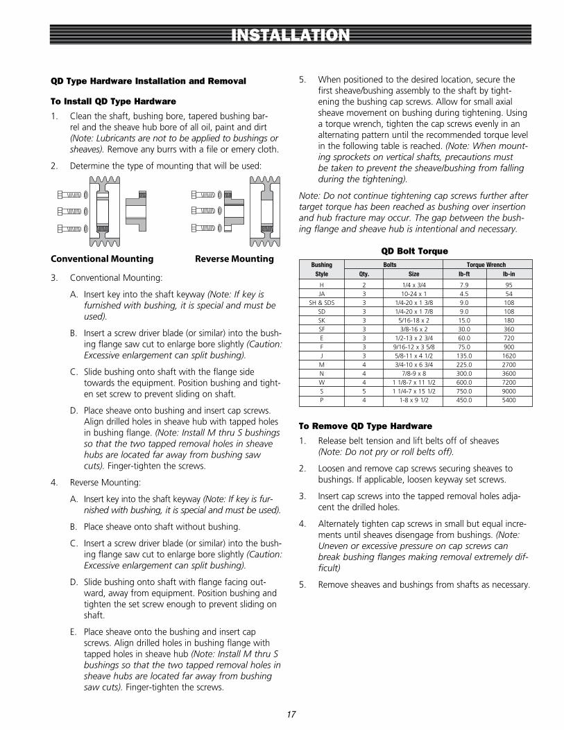
To Install QD Type Hardware
1 . Clean the shaft, bushing bore, tapered bushing bar-rel and the sheave hub bore of all oil, paint and dirt (Note: Lubricants are not to be applied to bushings or sheaves). Remove any burrs with a file or emery cloth .
2 . Determine the type of mounting that will be used:
Conventional Mounting Reverse Mounting
3 . Conventional Mounting:
A . Insert key into the shaft keyway (Note: If key is furnished with bushing, it is special and must be used).
B . Insert a screw driver blade (or similar) into the bush-ing flange saw cut to enlarge bore slightly (Caution: Excessive enlargement can split bushing).
C . Slide bushing onto shaft with the flange side towards the equipment . Position bushing and tight-en set screw to prevent sliding on shaft .
D . Place sheave onto bushing and insert cap screws . Align drilled holes in sheave hub with tapped holes in bushing flange . (Note: Install M thru S bushings so that the two tapped removal holes in sheave hubs are located far away from bushing saw cuts). Finger-tighten the screws .
4 . Reverse Mounting:
A . Insert key into the shaft keyway (Note: If key is fur-nished with bushing, it is special and must be used).
B . Place sheave onto shaft without bushing .
C . Insert a screw driver blade (or similar) into the bush-ing flange saw cut to enlarge bore slightly (Caution: Excessive enlargement can split bushing).
D . Slide bushing onto shaft with flange facing out-ward, away from equipment . Position bushing and tighten the set screw enough to prevent sliding on shaft .
E . Place sheave onto the bushing and insert cap screws . Align drilled holes in bushing flange with tapped holes in sheave hub (Note: Install M thru S bushings so that the two tapped removal holes in sheave hubs are located far away from bushing saw cuts). Finger-tighten the screws .
5 . When positioned to the desired location, secure the first sheave/bushing assembly to the shaft by tight-ening the bushing cap screws . Allow for small axial sheave movement on bushing during tightening . Using a torque wrench, tighten the cap screws evenly in an alternating pattern until the recommended torque level in the following table is reached . (Note: When mount-ing sprockets on vertical shafts, precautions must be taken to prevent the sheave/bushing from falling during the tightening).
Note: Do not continue tightening cap screws further after target torque has been reached as bushing over insertion and hub fracture may occur. The gap between the bush-ing flange and sheave hub is intentional and necessary.
QD Bolt Torque Bushing Bolts Torque Wrench Style Qty. Size lb-ft lb-in
H 2 1/4 x 3/4 7 .9 95 JA 3 10-24 x 1 4 .5 54 SH & SDS 3 1/4-20 x 1 3/8 9 .0 108 SD 3 1/4-20 x 1 7/8 9 .0 108 SK 3 5/16-18 x 2 15 .0 180 SF 3 3/8-16 x 2 30 .0 360 E 3 1/2-13 x 2 3/4 60 .0 720 F 3 9/16-12 x 3 5/8 75 .0 900 J 3 5/8-11 x 4 1/2 135 .0 1620 M 4 3/4-10 x 6 3/4 225 .0 2700 N 4 7/8-9 x 8 300 .0 3600 W 4 1 1/8-7 x 11 1/2 600 .0 7200 S 5 1 1/4-7 x 15 1/2 750 .0 9000 P 4 1-8 x 9 1/2 450 .0 5400
To Remove QD Type Hardware
1 . Release belt tension and lift belts off of sheaves (Note: Do not pry or roll belts off).
2 . Loosen and remove cap screws securing sheaves to bushings . If applicable, loosen keyway set screws .
3 . Insert cap screws into the tapped removal holes adja-cent the drilled holes .
4 . Alternately tighten cap screws in small but equal incre-ments until sheaves disengage from bushings . (Note: Uneven or excessive pressure on cap screws can break bushing flanges making removal extremely dif-ficult)
5 . Remove sheaves and bushings from shafts as necessary .
BELT STORAGE AND HANDLING
18
Storage Recommendations
Proper preventive maintenance should not be limited to the actual belt drive operating on equipment, but should also include following proper storage procedures . In order to retain their serviceability and dimensions, proper stor-age procedures must be followed for all belt types . Quite often premature belt failures can be traced to improper belt storage procedures that damaged the belt before it was installed on the drive . By following a few common sense steps, these types of belt failures can be avoided .
General Guidelines
Recommended
Belts should be stored in a cool and dry environment with no direct sunlight . Ideally, less than 85˚ F and 70% relative humidity .
Store on shelves or in boxes or containers . If the belt is pack-aged in a box, like Poly Chain® GT® Carbon™ belts, store the belt in its individual box .
V-belts may be stored by hanging on a wall rack if they are hung on a saddle or diameter at least as large as the mini-mum diameter sheave recommended for the belt cross sec-tion .
When the belts are stored, they must not be bent to diam-eters smaller than the minimum recommended sheave or sprocket diameter for that cross section . (see Technical Information section) Belts should not be stored with back bends that are less than 1 .3 times the minimum recom-mended sheave or sprocket diameter for that cross section .
If stored in containers, make sure that the belt is not dis-torted when in the container . Limit the contents in a con-tainer so that the belts at the bottom of the container are not damaged by the weight of the rest of the belts in the container .
Not Recommended
Belts should not be stored near windows, which may expose the belts to direct sunlight or moisture .
Belts should not be stored near heaters, radiators, or in the direct airflow of heating devices .
Belts should not be stored near any devices that generate ozone . Ozone generating devices include transformers and electric motors .
Belts should not be stored where they are exposed to sol-vents or chemicals in the atmosphere .
Do not store belts on the floor unless they are in a protec-tive container . Floor locations are exposed to traffic that may damage the belts .
Do not crimp belts during handling or while stored .
Belts are crimped by bending them to a diameter smaller than the minimum recommended diameter sheave or sprocket for that cross section . Do not use ties or tape to pull belt spans tightly together near the “end” of the belt . This will crimp the belt and cause premature belt failure . Do not hang on a small diameter pin that suspends all of the belt weight and bends the belt to a diameter smaller than the minimum recommended sheave or sprocket diameter . Improper storage will damage the tensile cord and the belt will fail prematurely . Handle belts carefully when removing from storage and going to the application . Do not inadver-tently crimp or damage the belts by careless handling .
Storage Methods
V-Belts
V-belts can be coiled in loops for storage purposes . Each coil results in a number of loops . One coil results in three loops, two coils results in five loops, etc . The maximum number of coils that can be used depends on the belt length . If coiling a belt for storage, consult the table on the next page and follow the limits shown .

BELT STORAGE AND HANDLING
19
Belt Cross Section Belt Length (in) Belt Length (mm) Number of Coils Number of Loops
3L, 4L, 5L, A, AX, Under 60 Under 1500 0 1
AA, B, BX, 3V, 60 up to 120 1500 up to 3000 1 3
3VX, 9R, 13R, 13C, 120 up to 180 3000 up to 4600 2 5
13CX, 13D, 16R, 180 and over 4600 and over 3 7
16C, 16CX, 9N
BB, C, CX, 5V, Under 75 Under 1900 0 1
5VX, 16D, 22C, 75 up to 144 1900 up to 3700 1 3
22CX, 15N 144 up to 240 3700 up to 6000 2 5
240 and over 6000 and over 3 7
CC, D, 22D, 32C Under 120 Under 3000 0 1
120 up to 240 3000 up to 6100 1 3
240 up to 330 6100 up to 8400 2 5
330 up to 420 8400 up to 10,600 3 7
420 and over 10,600 and over 4 9
8V, 8VX, 25N Under 180 Under 4600 0 1
80 up to 270 4600 up to 6900 1 3
270 up to 390 6900 up to 9900 2 5
390 up to 480 9900 up to 12,200 3 7
Over 480 12,200 and over 4 9
PowerBand® V-Belts, Synchronous Belts, Micro-V® Belts
Poly Chain® GT® Carbon™ belts are shipped in individual boxes . Poly Chain® GT® Carbon™ belts should be stored in the box in which it was shipped .
These belts may be stored by hanging on a wall rack if they are hung on a saddle or diameter at least as large as the minimum diameter sheave or sprocket recommended for the belt cross section, and the belts are not distorted .
PowerBand® V-belts, Synchronous belts, and Micro-V® belts up to 120 inches (3000 mm) may be stored in a nested con-figuration . Nests are formed by laying a belt on its side on a flat surface and placing as many belts inside the first belt as possible without undue force . When nests are formed, do not bend the belts to a diameter that is smaller than the minimum recommended sheave or sprocket diameter . Nests may be stacked without damaging the belts if they are tight and stacked with each nest rotated 180˚ from the nest below .
PowerBand® V-belts and Micro-V® belts over 120 inches (3000 mm) may be rolled up and tied for shipment . These individual rolls may be stacked for easy storage . When the belts are rolled, they must not be bent to a diameter that is smaller than the minimum diameter recommended for the cross section .
Variable Speed V-Belts
Variable speed belts have a thicker cross section and are more sensitive to distortion than other V-belts . Do not hang variable speed belts from pins, racks, or saddles . Store vari-able speed belts on their edge on shelves . Variable speed belts that are in sleeves may be stacked, taking care to avoid distorting the belts at the bottom of the stack .
Storage Effects
In order to retain their serviceability and dimensions, proper storage procedures must be followed for all belt types . Quite often premature belt failures can be traced to improper belt storage procedures that damaged the belt before it was installed on the drive .
Belts may be stored up to six years if properly stored at tem-peratures less than 85˚F and relative humidity less than 70% .
If the storage temperature is higher than 85˚ F, the storage limit for normal service performance is reduced by one half for each 15˚F increase in temperature . Belts should never be stored at temperatures above 115˚F .
At relative humidity levels above 70%, fungus or mildew may form on stored belts . This has minimal affect on belt performance, but should be avoided .
When equipment is stored for prolonged periods of time (over six months), the belt tension should be relaxed so that the belt does not take a set, and the storage environment should meet the 85˚F and 70% or less relative humidity con-dition . If this is not possible, belts should be removed and stored separately in a proper environment .

BELT IDENTIFICATION
When preventive maintenance inspections indicate that belts need replacing, it is important to install the correct belts .
Consequently, it is important to identify the various types and sizes of belts available, and then quickly be able to specify the correct replacement .
The information on the following pages will help identify the belt types used in industry . Gates makes a belt to fit nearly any application .
V-Belts
20
Metric Power™ V-Belts
SPZ/XPZ SPA/XPA SPB*/XPB SPC*/XPC
*available in Predator® belt construction
Tri-Power® V-Belts PowerBand® – Hi-Power® II, Super HC®
and Predator®
3/8"
3/8"
21/64"
1"
7/8"
21/64"
53/64"
1"
35/64"
5/8"
35/64"
5/8"
13mm
16mm
37/64"
5/8"
3/8"
1"
29/32"
23/64"
3/8"
23/64"
37/64"
5/8"18mm
22mm
3/8"5/8"
23/64" 37/64"
1"
29/32"
5/8"
35/64"
1"
7/8"
1/2"
7/8"
1-1/4"1-1/2”
29/32"3/4"
17/32"5/16"
1/2"21/32"
7/8"
17/32"13/32"5/16"
1/2"
11/32"
21/32"
7/16"
21/32"
13/32"
1/2"
7/8"
17/32"5/16"
21/32"
13/32"
7/8"
9/16"
1-1/4"
25/32"
9/16"
7/8"
3VP
3VX
3VX
3V
3V5VP
BX CX
CP
CC
D EDB
B
AX
A
A
CPBP
SPCPSPBP
AP
5VP
5VX
8VP
8VP
8V
8V
8VX
5V
5V
5VX
Super HC® V-Belts
* * *
3/8"
3/8"
21/64"
1"
7/8"
21/64"
53/64"
1"
35/64"
5/8"
35/64"
5/8"
13mm
16mm
37/64"
5/8"
3/8"
1"
29/32"
23/64"
3/8"
23/64"
37/64"
5/8"18mm
22mm
3/8"5/8"
23/64" 37/64"
1"
29/32"
5/8"
35/64"
1"
7/8"
1/2"
7/8"
1-1/4"1-1/2”
29/32"3/4"
17/32"5/16"
1/2"21/32"
7/8"
17/32"13/32"5/16"
1/2"
11/32"
21/32"
7/16"
21/32"
13/32"
1/2"
7/8"
17/32"5/16"
21/32"
13/32"
7/8"
9/16"
1-1/4"
25/32"
9/16"
7/8"
3VP
3VX
3VX
3V
3V5VP
BX CX
CP
CC
D EDB
B
AX
A
A
CPBP
SPCPSPBP
AP
5VP
5VX
8VP
8VP
8V
8V
8VX
5V
5V
5VX
3/8"
3/8"
21/64"
1"
7/8"
21/64"
53/64"
1"
35/64"
5/8"
35/64"
5/8"
13mm
16mm
37/64"
5/8"
3/8"
1"
29/32"
23/64"
3/8"
23/64"
37/64"
5/8"18mm
22mm
3/8"5/8"
23/64" 37/64"
1"
29/32"
5/8"
35/64"
1"
7/8"
1/2"
7/8"
1-1/4"1-1/2”
29/32"3/4"
17/32"5/16"
1/2"21/32"
7/8"
17/32"13/32"5/16"
1/2"
11/32"
21/32"
7/16"
21/32"
13/32"
1/2"
7/8"
17/32"5/16"
21/32"
13/32"
7/8"
9/16"
1-1/4"
25/32"
9/16"
7/8"
3VP
3VX
3VX
3V
3V5VP
BX CX
CP
CC
D EDB
B
AX
A
A
CPBP
SPCPSPBP
AP
5VP
5VX
8VP
8VP
8V
8V
8VX
5V
5V
5VX3/8"
3/8"
21/64"
1"
7/8"
21/64"
53/64"
1"
35/64"
5/8"
35/64"
5/8"
13mm
16mm
37/64"
5/8"
3/8"
1"
29/32"
23/64"
3/8"
23/64"
37/64"
5/8"18mm
22mm
3/8"5/8"
23/64" 37/64"
1"
29/32"
5/8"
35/64"
1"
7/8"
1/2"
7/8"
1-1/4"1-1/2”
29/32"3/4"
17/32"5/16"
1/2"21/32"
7/8"
17/32"13/32"5/16"
1/2"
11/32"
21/32"
7/16"
21/32"
13/32"
1/2"
7/8"
17/32"5/16"
21/32"
13/32"
7/8"
9/16"
1-1/4"
25/32"
9/16"
7/8"
3VP
3VX
3VX
3V
3V5VP
BX CX
CP
CC
D EDB
B
AX
A
A
CPBP
SPCPSPBP
AP
5VP
5VX
8VP
8VP
8V
8V
8VX
5V
5V
5VX
3/8"
3/8"
21/64"
1"
7/8"
21/64"
53/64"
1"
35/64"
5/8"
35/64"
5/8"
13mm
16mm
37/64"
5/8"
3/8"
1"
29/32"
23/64"
3/8"
23/64"
37/64"
5/8"18mm
22mm
3/8"5/8"
23/64" 37/64"
1"
29/32"
5/8"
35/64"
1"
7/8"
1/2"
7/8"
1-1/4"1-1/2”
29/32"3/4"
17/32"5/16"
1/2"21/32"
7/8"
17/32"13/32"5/16"
1/2"
11/32"
21/32"
7/16"
21/32"
13/32"
1/2"
7/8"
17/32"5/16"
21/32"
13/32"
7/8"
9/16"
1-1/4"
25/32"
9/16"
7/8"
3VP
3VX
3VX
3V
3V5VP
BX CX
CP
CC
D EDB
B
AX
A
A
CPBP
SPCPSPBP
AP
5VP
5VX
8VP
8VP
8V
8V
8VX
5V
5V
5VX
Hi-Power® II V-Belts
3/8"
3/8"
21/64"
1"
7/8"
21/64"
53/64"
1"
35/64"
5/8"
35/64"
5/8"
13mm
16mm
37/64"
5/8"
3/8"
1"
29/32"
23/64"
3/8"
23/64"
37/64"
5/8"18mm
22mm
3/8"5/8"
23/64" 37/64"
1"
29/32"
5/8"
35/64"
1"
7/8"
1/2"
7/8"
1-1/4"1-1/2”
29/32"3/4"
17/32"5/16"
1/2"21/32"
7/8"
17/32"13/32"5/16"
1/2"
11/32"
21/32"
7/16"
21/32"
13/32"
1/2"
7/8"
17/32"5/16"
21/32"
13/32"
7/8"
9/16"
1-1/4"
25/32"
9/16"
7/8"
3VP
3VX
3VX
3V
3V5VP
BX CX
CP
CC
D EDB
B
AX
A
A
CPBP
SPCPSPBP
AP
5VP
5VX
8VP
8VP
8V
8V
8VX
5V
5V
5VX
3/8"
3/8"
21/64"
1"
7/8"
21/64"
53/64"
1"
35/64"
5/8"
35/64"
5/8"
13mm
16mm
37/64"
5/8"
3/8"
1"
29/32"
23/64"
3/8"
23/64"
37/64"
5/8"18mm
22mm
3/8"5/8"
23/64" 37/64"
1"
29/32"
5/8"
35/64"
1"
7/8"
1/2"
7/8"
1-1/4"1-1/2”
29/32"3/4"
17/32"5/16"
1/2"21/32"
7/8"
17/32"13/32"5/16"
1/2"
11/32"
21/32"
7/16"
21/32"
13/32"
1/2"
7/8"
17/32"5/16"
21/32"
13/32"
7/8"
9/16"
1-1/4"
25/32"
9/16"
7/8"
3VP
3VX
3VX
3V
3V5VP
BX CX
CP
CC
D EDB
B
AX
A
A
CPBP
SPCPSPBP
AP
5VP
5VX
8VP
8VP
8V
8V
8VX
5V
5V
5VX
* * *
Predator® V-Belts
SPCPSPBP8VP5VPCPBPAP
1/2”
5/16”
21/32”
13/32”
7/8”
17/32” 7/8”
5/8”
1”
16mm22mm
13mm 18mm35/64”
Super HC® V-Belts
8VX5VX3VX8V5V3V
3/8”
21/64”
5/8”
35/64”
1”
7/8” 35/64”
3/8”
5/8”
1”
53/64”
21/64”
Hi-Power® II V-Belts
EDCBA
1/2”
5/16”
21/32”
13/32”
7/8”
17/32”29/32”
1-1/4”1-1/2”
3/4”
Tri-Power® V-Belts
CXBXAX
1/2”
5/16” 17/32”
21/32” 7/8”
13/32”
Metric Power™ V-Belts
17X13X10XSPCXPC
SPBXPB
SPAXPA
SPZXPZ
10mm
8mm
13mm
10mm
16mm
13mm6mm
22mm
10mm13mm
17mm
8mm 10mm18mm
Multi-Speed Belts
Truflex® & PoweRated® Light Duty V-Belts
5L (3)4L (2)3L (1)2L (0)
1/4”
1/8”
3/8”
7/32’
1/2”
5/16”
21/32”
3/8”
Truflex®
PoweRated®
69_5LK
68_4LK
67_3LK
3/8”
7/32’
1/2”
5/16”
21/32”
3/8”
PowerBand® Joined Belts
Single V-Belts Synchronous Belts
Predator® PowerBand® Belts
Super HC® & Super HC®
Molded NotchPowerBand® Belts
Hi-Power® II PowerBand® Belts
Micro-V® Belts J Section
K* Section
L Section
M Section
5/32”3/32”
13/64”9/64”
1/4”3/16”
3/8”
1/2”
Round Belts
Polyflex® and Polyflex® JB®
11M7M5M3M
1/8”3/32”
3/16”
1/8’
9/32”
7/32”
7/16”
9/32”
11M7M5M3M3/32” 1/8” 7/32” 9/32”
Round Endless Power Round™
Heavy-DutyConstruction
9/16”
7/16”
1/2”
9/16”
1/4”
5/16”
3/8”
Poly Chain® GT® Carbon™ Belts
14mmPitch
8mmPitch
A
B C
PowerGrip® GT®2 Belts2mm Pitch
3mm Pitch
5mm** Pitch
8mm Pitch
14mm Pitch B C
A
PowerGrip® HTD® Belts3mm Pitch
5mm Pitch
20mm Pitch B
C
A
PowerGrip® Timing BeltsMXL
XL
L
H
XH
BC
A
XXH
PowerGrip® Twin Power® Belts
A
Timing
GT®2
A
Synchro-Power® Polyurethane Belts
A
Timing
Metric
A
A
10X 13X 17X
21
BELT IDENTIFICATION
Standard Polyflex® V-Belts
Micro-V® Belts
Polyflex® JB® V-Belts
Dubl-V Belts
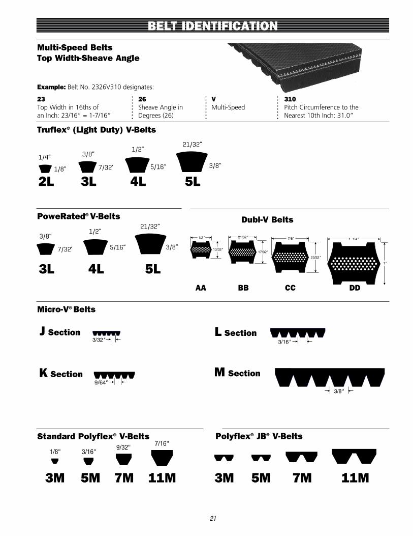
Multi-Speed Belts Top Width-Sheave Angle
Example: Belt No . 2326V310 designates:
23 26 V 310 Top Width in 16ths of Sheave Angle in Multi-Speed Pitch Circumference to the an Inch: 23/16” = 1-7/16” Degrees (26) Nearest 10th Inch: 31 .0”
Truflex® (Light Duty) V-Belts
J SECTION
3/32"
L SECTION
3/16"
M SECTION
3/8"
J SECTION
3/32"
L SECTION
3/16"
M SECTION
3/8"
J SECTION
3/32"
L SECTION
3/16"
M SECTION
3/8"
J SECTION
3/32"
L SECTION
3/16"
M SECTION
3/8"
J Section L Section
K Section M Section
Predator® V-Belts
SPCPSPBP8VP5VPCPBPAP
1/2”
5/16”
21/32”
13/32”
7/8”
17/32” 7/8”
5/8”
1”
16mm22mm
13mm 18mm35/64”
Super HC® V-Belts
8VX5VX3VX8V5V3V
3/8”
21/64”
5/8”
35/64”
1”
7/8” 35/64”
3/8”
5/8”
1”
53/64”
21/64”
Hi-Power® II V-Belts
EDCBA
1/2”
5/16”
21/32”
13/32”
7/8”
17/32”29/32”
1-1/4”1-1/2”
3/4”
Tri-Power® V-Belts
CXBXAX
1/2”
5/16” 17/32”
21/32” 7/8”
13/32”
Metric Power™ V-Belts
17X13X10XSPCXPC
SPBXPB
SPAXPA
SPZXPZ
10mm
8mm
13mm
10mm
16mm
13mm6mm
22mm
10mm13mm
17mm
8mm 10mm18mm
Multi-Speed Belts
Truflex® & PoweRated® Light Duty V-Belts
5L (3)4L (2)3L (1)2L (0)
1/4”
1/8”
3/8”
7/32’
1/2”
5/16”
21/32”
3/8”
Truflex®
PoweRated®
69_5LK
68_4LK
67_3LK
3/8”
7/32’
1/2”
5/16”
21/32”
3/8”
PowerBand® Joined Belts
Single V-Belts Synchronous Belts
Predator® PowerBand® Belts
Super HC® & Super HC®
Molded NotchPowerBand® Belts
Hi-Power® II PowerBand® Belts
Micro-V® Belts J Section
K* Section
L Section
M Section
5/32”3/32”
13/64”9/64”
1/4”3/16”
3/8”
1/2”
Round Belts
Polyflex® and Polyflex® JB®
11M7M5M3M
1/8”3/32”
3/16”
1/8’
9/32”
7/32”
7/16”
9/32”
11M7M5M3M3/32” 1/8” 7/32” 9/32”
Round Endless Power Round™
Heavy-DutyConstruction
9/16”
7/16”
1/2”
9/16”
1/4”
5/16”
3/8”
Poly Chain® GT® Carbon™ Belts
14mmPitch
8mmPitch
A
B C
PowerGrip® GT®2 Belts2mm Pitch
3mm Pitch
5mm** Pitch
8mm Pitch
14mm Pitch B C
A
PowerGrip® HTD® Belts3mm Pitch
5mm Pitch
20mm Pitch B
C
A
PowerGrip® Timing BeltsMXL
XL
L
H
XH
BC
A
XXH
PowerGrip® Twin Power® Belts
A
Timing
GT®2
A
Synchro-Power® Polyurethane Belts
A
Timing
Metric
A
A
1/8" 3/16"9/32"
7/16"
3M 3M 5M 5M 7M 7M 11M 11M
PoweRated® V-Belts
3L 4L 5L
Predator® V-Belts
SPCPSPBP8VP5VPCPBPAP
1/2”
5/16”
21/32”
13/32”
7/8”
17/32” 7/8”
5/8”
1”
16mm22mm
13mm 18mm35/64”
Super HC® V-Belts
8VX5VX3VX8V5V3V
3/8”
21/64”
5/8”
35/64”
1”
7/8” 35/64”
3/8”
5/8”
1”
53/64”
21/64”
Hi-Power® II V-Belts
EDCBA
1/2”
5/16”
21/32”
13/32”
7/8”
17/32”29/32”
1-1/4”1-1/2”
3/4”
Tri-Power® V-Belts
CXBXAX
1/2”
5/16” 17/32”
21/32” 7/8”
13/32”
Metric Power™ V-Belts
17X13X10XSPCXPC
SPBXPB
SPAXPA
SPZXPZ
10mm
8mm
13mm
10mm
16mm
13mm6mm
22mm
10mm13mm
17mm
8mm 10mm18mm
Multi-Speed Belts
Truflex® & PoweRated® Light Duty V-Belts
5L (3)4L (2)3L (1)2L (0)
1/4”
1/8”
3/8”
7/32’
1/2”
5/16”
21/32”
3/8”
Truflex®
PoweRated®
69_5LK
68_4LK
67_3LK
3/8”
7/32’
1/2”
5/16”
21/32”
3/8”
PowerBand® Joined Belts
Single V-Belts Synchronous Belts
Predator® PowerBand® Belts
Super HC® & Super HC®
Molded NotchPowerBand® Belts
Hi-Power® II PowerBand® Belts
Micro-V® Belts J Section
K* Section
L Section
M Section
5/32”3/32”
13/64”9/64”
1/4”3/16”
3/8”
1/2”
Round Belts
Polyflex® and Polyflex® JB®
11M7M5M3M
1/8”3/32”
3/16”
1/8’
9/32”
7/32”
7/16”
9/32”
11M7M5M3M3/32” 1/8” 7/32” 9/32”
Round Endless Power Round™
Heavy-DutyConstruction
9/16”
7/16”
1/2”
9/16”
1/4”
5/16”
3/8”
Poly Chain® GT® Carbon™ Belts
14mmPitch
8mmPitch
A
B C
PowerGrip® GT®2 Belts2mm Pitch
3mm Pitch
5mm** Pitch
8mm Pitch
14mm Pitch B C
A
PowerGrip® HTD® Belts3mm Pitch
5mm Pitch
20mm Pitch B
C
A
PowerGrip® Timing BeltsMXL
XL
L
H
XH
BC
A
XXH
PowerGrip® Twin Power® Belts
A
Timing
GT®2
A
Synchro-Power® Polyurethane Belts
A
Timing
Metric
A
A
2L 3L 4L 5L
Predator® V-Belts
SPCPSPBP8VP5VPCPBPAP
1/2”
5/16”
21/32”
13/32”
7/8”
17/32” 7/8”
5/8”
1”
16mm22mm
13mm 18mm35/64”
Super HC® V-Belts
8VX5VX3VX8V5V3V
3/8”
21/64”
5/8”
35/64”
1”
7/8” 35/64”
3/8”
5/8”
1”
53/64”
21/64”
Hi-Power® II V-Belts
EDCBA
1/2”
5/16”
21/32”
13/32”
7/8”
17/32”29/32”
1-1/4”1-1/2”
3/4”
Tri-Power® V-Belts
CXBXAX
1/2”
5/16” 17/32”
21/32” 7/8”
13/32”
Metric Power™ V-Belts
17X13X10XSPCXPC
SPBXPB
SPAXPA
SPZXPZ
10mm
8mm
13mm
10mm
16mm
13mm6mm
22mm
10mm13mm
17mm
8mm 10mm18mm
Multi-Speed Belts
Truflex® & PoweRated® Light Duty V-Belts
5L (3)4L (2)3L (1)2L (0)
1/4”
1/8”
3/8”
7/32’
1/2”
5/16”
21/32”
3/8”
Truflex®
PoweRated®
69_5LK
68_4LK
67_3LK
3/8”
7/32’
1/2”
5/16”
21/32”
3/8”
PowerBand® Joined Belts
Single V-Belts Synchronous Belts
Predator® PowerBand® Belts
Super HC® & Super HC®
Molded NotchPowerBand® Belts
Hi-Power® II PowerBand® Belts
Micro-V® Belts J Section
K* Section
L Section
M Section
5/32”3/32”
13/64”9/64”
1/4”3/16”
3/8”
1/2”
Round Belts
Polyflex® and Polyflex® JB®
11M7M5M3M
1/8”3/32”
3/16”
1/8’
9/32”
7/32”
7/16”
9/32”
11M7M5M3M3/32” 1/8” 7/32” 9/32”
Round Endless Power Round™
Heavy-DutyConstruction
9/16”
7/16”
1/2”
9/16”
1/4”
5/16”
3/8”
Poly Chain® GT® Carbon™ Belts
14mmPitch
8mmPitch
A
B C
PowerGrip® GT®2 Belts2mm Pitch
3mm Pitch
5mm** Pitch
8mm Pitch
14mm Pitch B C
A
PowerGrip® HTD® Belts3mm Pitch
5mm Pitch
20mm Pitch B
C
A
PowerGrip® Timing BeltsMXL
XL
L
H
XH
BC
A
XXH
PowerGrip® Twin Power® Belts
A
Timing
GT®2
A
Synchro-Power® Polyurethane Belts
A
Timing
Metric
A
A
AA
J SECTION
3/32"
L SECTION
3/16"
M SECTION
3/8"
BB
J SECTION
3/32"
L SECTION
3/16"
M SECTION
3/8"
CC
J SECTION
3/32"
L SECTION
3/16"
M SECTION
3/8"
DD
J SECTION
3/32"
L SECTION
3/16"
M SECTION
3/8"

PowerGrip® GT®2 Belts PowerGrip® Timing Belts
BELT IDENTIFICATION
Synchronous Belts
Poly Chain® GT® Carbon™ Belts
8M 8mm Pitch
8M 8mm Pitch
14M 14mm Pitch
14M 14mm Pitch
All synchronous belts are identified in a similar manner, in either English or metric units . Belts are measured by:
1. Pitch: Distance in inches or millimeters between two adjacent tooth centers as measured on the belt pitch line .
2. Pitch Length: Total length (circumference) in inches or millimeters as measured along the pitch line . It is equal to the pitch multiplied by the number of teeth in the belt .
3. Width: Denoted in inches or millimeters .
22
Pitch
*also available in TruMotion® belt construction
PowerGrip® HTD® Belts
3M 3mm Pitch
L .375" Pitch
H .500" Pitch
XH .875" Pitch
XXH 1.250" Pitch
5M 5mm Pitch
8M 8mm Pitch
Pitch
PitchPitch
14M 14mm Pitch
20M 20mm Pitch
Predator® V-Belts
SPCPSPBP8VP5VPCPBPAP
1/2”
5/16”
21/32”
13/32”
7/8”
17/32” 7/8”
5/8”
1”
16mm22mm
13mm 18mm35/64”
Super HC® V-Belts
8VX5VX3VX8V5V3V
3/8”
21/64”
5/8”
35/64”
1”
7/8” 35/64”
3/8”
5/8”
1”
53/64”
21/64”
Hi-Power® II V-Belts
EDCBA
1/2”
5/16”
21/32”
13/32”
7/8”
17/32”29/32”
1-1/4”1-1/2”
3/4”
Tri-Power® V-Belts
CXBXAX
1/2”
5/16” 17/32”
21/32” 7/8”
13/32”
Metric Power™ V-Belts
17X13X10XSPCXPC
SPBXPB
SPAXPA
SPZXPZ
10mm
8mm
13mm
10mm
16mm
13mm6mm
22mm
10mm13mm
17mm
8mm 10mm18mm
Multi-Speed Belts
Truflex® & PoweRated® Light Duty V-Belts
5L (3)4L (2)3L (1)2L (0)
1/4”
1/8”
3/8”
7/32’
1/2”
5/16”
21/32”
3/8”
Truflex®
PoweRated®
69_5LK
68_4LK
67_3LK
3/8”
7/32’
1/2”
5/16”
21/32”
3/8”
PowerBand® Joined Belts
Single V-Belts Synchronous Belts
Predator® PowerBand® Belts
Super HC® & Super HC®
Molded NotchPowerBand® Belts
Hi-Power® II PowerBand® Belts
Micro-V® Belts J Section
K* Section
L Section
M Section
5/32”3/32”
13/64”9/64”
1/4”3/16”
3/8”
1/2”
Round Belts
Polyflex® and Polyflex® JB®
11M7M5M3M
1/8”3/32”
3/16”
1/8’
9/32”
7/32”
7/16”
9/32”
11M7M5M3M3/32” 1/8” 7/32” 9/32”
Round Endless Power Round™
Heavy-DutyConstruction
9/16”
7/16”
1/2”
9/16”
1/4”
5/16”
3/8”
Poly Chain® GT® Carbon™ Belts
14mmPitch
8mmPitch
A
B C
PowerGrip® GT®2 Belts2mm Pitch
3mm Pitch
5mm** Pitch
8mm Pitch
14mm Pitch B C
A
PowerGrip® HTD® Belts3mm Pitch
5mm Pitch
20mm Pitch B
C
A
PowerGrip® Timing BeltsMXL
XL
L
H
XH
BC
A
XXH
PowerGrip® Twin Power® Belts
A
Timing
GT®2
A
Synchro-Power® Polyurethane Belts
A
Timing
Metric
A
A
5M 5mm Pitch
*
3M 3mm Pitch
*
2M 2mm Pitch
* MXL .080" Pitch
*
XL .200" Pitch
*

BELT IDENTIFICATION
23
Twin Power® Timing Belts
XL .200” Pitch
L .375” Pitch
H .500” Pitch
3M 3mm Pitch
5M 5mm Pitch
8M 8mm Pitch
14M 14mm Pitch
Twin Power® PowerGrip® GT®2 Belts
Pitch
Pitch
Predator® V-Belts
SPCPSPBP8VP5VPCPBPAP
1/2”
5/16”
21/32”
13/32”
7/8”
17/32” 7/8”
5/8”
1”
16mm22mm
13mm 18mm35/64”
Super HC® V-Belts
8VX5VX3VX8V5V3V
3/8”
21/64”
5/8”
35/64”
1”
7/8” 35/64”
3/8”
5/8”
1”
53/64”
21/64”
Hi-Power® II V-Belts
EDCBA
1/2”
5/16”
21/32”
13/32”
7/8”
17/32”29/32”
1-1/4”1-1/2”
3/4”
Tri-Power® V-Belts
CXBXAX
1/2”
5/16” 17/32”
21/32” 7/8”
13/32”
Metric Power™ V-Belts
17X13X10XSPCXPC
SPBXPB
SPAXPA
SPZXPZ
10mm
8mm
13mm
10mm
16mm
13mm6mm
22mm
10mm13mm
17mm
8mm 10mm18mm
Multi-Speed Belts
Truflex® & PoweRated® Light Duty V-Belts
5L (3)4L (2)3L (1)2L (0)
1/4”
1/8”
3/8”
7/32’
1/2”
5/16”
21/32”
3/8”
Truflex®
PoweRated®
69_5LK
68_4LK
67_3LK
3/8”
7/32’
1/2”
5/16”
21/32”
3/8”
PowerBand® Joined Belts
Single V-Belts Synchronous Belts
Predator® PowerBand® Belts
Super HC® & Super HC®
Molded NotchPowerBand® Belts
Hi-Power® II PowerBand® Belts
Micro-V® Belts J Section
K* Section
L Section
M Section
5/32”3/32”
13/64”9/64”
1/4”3/16”
3/8”
1/2”
Round Belts
Polyflex® and Polyflex® JB®
11M7M5M3M
1/8”3/32”
3/16”
1/8’
9/32”
7/32”
7/16”
9/32”
11M7M5M3M3/32” 1/8” 7/32” 9/32”
Round Endless Power Round™
Heavy-DutyConstruction
9/16”
7/16”
1/2”
9/16”
1/4”
5/16”
3/8”
Poly Chain® GT® Carbon™ Belts
14mmPitch
8mmPitch
A
B C
PowerGrip® GT®2 Belts2mm Pitch
3mm Pitch
5mm** Pitch
8mm Pitch
14mm Pitch B C
A
PowerGrip® HTD® Belts3mm Pitch
5mm Pitch
20mm Pitch B
C
A
PowerGrip® Timing BeltsMXL
XL
L
H
XH
BC
A
XXH
PowerGrip® Twin Power® Belts
A
Timing
GT®2
A
Synchro-Power® Polyurethane Belts
A
Timing
Metric
A
A

Pitch
BELT IDENTIFICATION
24
Synchro-Power® Polyurethane Belts
T5 5mm Pitch
T10 10mm Pitch
AT5 5mm Pitch
AT10 10mm Pitch
AT20 20mm Pitch
8M HTD 8mm Pitch
5M HTD 5mm Pitch
14M HTD 14mm Pitch
T20 20mm Pitch
Pitch
Pitch

Narrow Section V-BeltsThese high capacity belts are used to substantially reduce drive costs and decrease space requirements . This V-belt handles the complete range of drive horsepower recom-mended with three narrow cross sections instead of the five regular cross sections needed for classical heavy-duty belts . Specified by 3V, 5V or 8V cross sections . Specify Gates Super HC® V-belts .
Classical Section V-BeltsThese are the original belts used in heavy duty applications . They are specified by cross section and standard length . The size is designated as A, B, C, D or E . The easiest way to select a replacement is by finding the belt number on the worn belt . If not legible, measure the belts outside circum-ference with a flexible tape, preferably while it is still on the drive .
Then, order the Gates Hi-Power® ll V-belt which has the next shorter standard length . For example: For an “A” section belt with a 28 .0” O .C ., order an A26 replacement belt .
Banded and Bandless BeltsBanded belts, also called wrapped or covered belts, have a fabric cover . Un-notched and generally with concave sidewalls, banded belts have rounded bottom corners and arched tops .
Bandless belts have no fabric cover, straight cut-edge side-walls, and special molded notches . The notches reduce bending stress which allows belts to run on smaller diameter sheaves than comparable non-notched banded belts .
Gates offers these two types in both the classical and nar-row sections . In the classical section, Gates Tri-Power® molded notch is available in AX, BX and CX cross sections . Its length is specified by the same standard belt number as other classical section belts .
Gates also offers Super HC® Molded Notch V-belts in 3VX, 5VX and 8VX sizes .
In both cases, an “X” is used in the belt number to desig-nate a molded notch construction . For example: An AX26 is a bandless, molded notch classical section belt . A 5VX1400 is a narrow section, bandless, molded notch belt with a 140” O .C .
25
BELT TYPES
Note: The revolutionary Gates belt construction is used in the notched belts .
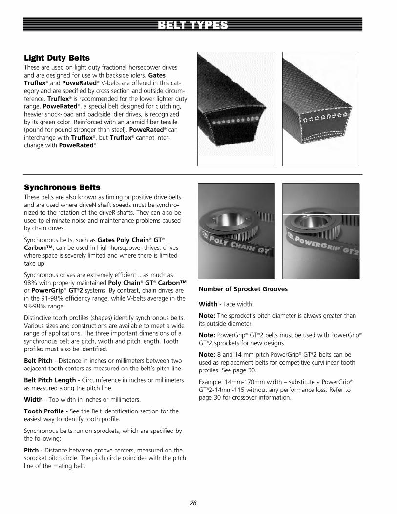
26
Light Duty BeltsThese are used on light duty fractional horsepower drives and are designed for use with backside idlers . Gates Truflex® and PoweRated® V-belts are offered in this cat-egory and are specified by cross section and outside circum-ference . Truflex® is recommended for the lower lighter duty range . PoweRated®, a special belt designed for clutching, heavier shock-load and backside idler drives, is recognized by its green color . Reinforced with an aramid fiber tensile (pound for pound stronger than steel) . PoweRated® can interchange with Truflex®, but Truflex® cannot inter-change with PoweRated® .
Synchronous BeltsThese belts are also known as timing or positive drive belts and are used where driveN shaft speeds must be synchro-nized to the rotation of the driveR shafts . They can also be used to eliminate noise and maintenance problems caused by chain drives .
Synchronous belts, such as Gates Poly Chain® GT® Carbon™, can be used in high horsepower drives, drives where space is severely limited and where there is limited take up .
Synchronous drives are extremely efficient . . . as much as 98% with properly maintained Poly Chain® GT® Carbon™ or PowerGrip® GT®2 systems . By contrast, chain drives are in the 91-98% efficiency range, while V-belts average in the 93-98% range .
Distinctive tooth profiles (shapes) identify synchronous belts . Various sizes and constructions are available to meet a wide range of applications . The three important dimensions of a synchronous belt are pitch, width and pitch length . Tooth profiles must also be identified .
Belt Pitch - Distance in inches or millimeters between two adjacent tooth centers as measured on the belt’s pitch line .
Belt Pitch Length - Circumference in inches or millimeters as measured along the pitch line .
Width - Top width in inches or millimeters .
Tooth Profile - See the Belt Identification section for the easiest way to identify tooth profile .
Synchronous belts run on sprockets, which are specified by the following:
Pitch - Distance between groove centers, measured on the sprocket pitch circle . The pitch circle coincides with the pitch line of the mating belt .
Number of Sprocket Grooves
Width - Face width .
Note: The sprocket’s pitch diameter is always greater than its outside diameter .
Note: PowerGrip® GT®2 belts must be used with PowerGrip® GT®2 sprockets for new designs .
Note: 8 and 14 mm pitch PowerGrip® GT®2 belts can be used as replacement belts for competitive curvilinear tooth profiles . See page 30 .
Example: 14mm-170mm width – substitute a PowerGrip® GT®2-14mm-115 without any performance loss . Refer to page 30 for crossover information .
BELT TYPES

Polyflex® JB® V-BeltsPolyflex® is a unique belt with a distinctive 60° belt angle and ribbed top specifically designed for long life in small diameter sheave drives . Polyflex® JB® is ideal for compact drives, drives with high speed ratios, and drives requiring especially smooth operation .
The “JB” refers to the belt’s configuration: two, three or five belts joined together to provide extra stability and improved performance . This joined belt style should be used instead of matched single belts whenever possible .
Polyflex® JB® belts are ideal for these applications:
• Milling, grinding or drilling machines• Lathes• Machine spindle drives• Centrifuges• Blowers• High speed compressors
Polyflex® JB® belts are specified by Top Width and
Effective Length
Multi-Speed Belts(Variable Speed Drives)
Multi-Speed belts have a distinct shape . Multi-Speed belt top widths are usually greater than their thicknesses . This permits a greater range of speed ratios than standard belts . Usually cogged or notched on the underside, Multi-Speed belts are specified for equipment which require changes in driveN speed during operation .
Multi-Speed belts are specified by Top Width, Outside Circumference, and the required Groove Angle . The groove angle can be measured from the drive pulleys .
Micro-V® or V-Ribbed BeltsGates Micro-V® belts outperform other V-ribbed belts because the tips of the “V” are truncated (shorter) . This shorter profile gives the new Micro-V belts increased flex-ibility, reduced heat buildup and allows them to operate at extra high speeds on smaller diameter sheaves .
Additional advantages of the truncated tips are: (1) the belt does not bottom in the sheave, therefore providing a higher degree of wedging and (2) the belt can better tolerate debris in the sheave groove . They are extremely smooth running and highly resistant to oil, heat and other adverse conditions .
Three cross sections are available for industrial applications: J, L and M .
BELT TYPES
27

BELT STYLES
28
Used on drives with little or no take-up, or as an emergency belt replacement .
Belting is sold on reels in standard V-belt cross sections . Easy-Splice V-belting ends are spliced with fasteners that require special assembly tools . Always use the correct fasteners with the correct belt type and cross section .
Nu-T-Link®, a high performance, linked belt, is also avail-able for use as emergency belting, and for drives where con-ditions are detrimental to rubber belts .
PowerBand belts were developed by Gates for drives sub-jected to pulsating loads, shock loads or extreme vibrations where single belts could flip over on the pulleys . A high-strength tie band permanently joins two or more belts to provide lateral rigidity . This keeps the belts running in a straight line in the pulley grooves . PowerBand® construction is offered with Gates Hi-Power® II, Super HC® and Super HC® Molded Notch Belts .
PowerBand® Belts
Spliced and Linked Belting
Gates Predator® V-belts are available in single, or multi-layered PowerBand® construction that adds strength, dura-bility, shear and tear resistance and lateral rigidity to handle the toughest shock-loaded applications .
Primary features of Predator® V-belts:
• Aramid tensile cords for extraordinary strength, durability and virtually zero stretch .
• Chloroprene rubber compounds for superb oil and heat resistance .
• Specially-treated extra tough cover withstands slip and shear forces at peak loads without generating excessive heat . It also fends off penetration by foreign materials .
• Gates curves that compensate for effects that occur when belts bend around a sheave for uniform loading and maximum life .
• Matched by request to maximize power absorption and belt life .
Predator® V-Belts

BELT STYLES
29
Round Endless BeltsRecommended for replacing leather belting on serpentine or quarter-turn drives . They are specified by Diameter and Inside Length .
If your current drive has leather or round endless belting, you should consider a new drive design . V-belt drives offer many advantages in performance, even on serpentine or quarter-turn drives .
Also available in Heavy-Duty PowerRound™ constructiom
PowerBack® V-BeltsPowerBack™ belts are “B” section V-belts with a flat back surface . The flat back surface makes PowerBack™ belts ideal for driving roll-to-roll conveyor applications .
Power Curve® V-BeltsPower Curve® belts are “B” section V-belts offering increased flexibility for demanding power turn conveyor applications . The belts “bend” around corners and drive the rollers in most conveyor applications .

30
Dubl-V BeltsA special version of Gates Hi-Power® II for serpentine drives where power is transmitted by both the top and bottom of the belt . Dubl-V belts are specified by A, B, C or D cross sec-tions, and by Effective Length .
Static Conductive BeltsStatic discharge can pose a hazard on belt drives that oper-ate in potentially explosive environments . Static discharge can also interfere with radios, electronic instruments, or controls used in a facility . While uncommon, static dis-charge can also cause bearing pitting if the discharge occurs through the bearing . Static conductivity is a required belt characteristic in these cases in order to prevent static dis-charge .
The Rubber Manufacturer’s Association (RMA) has published Bulletin IP 3-3 for static conductivity . Static conductivity testing involves using an ohmmeter to pass an electrical current with a nominal open circuit 500 volt poten-tial through a belt . The test should be performed with the belt off of the belt drive . The belt’s resistance is measured by placing electrodes 8 .5 inches apart on the clean driving surface of the belt . A resistance reading of six (6) meg-ohms or more constitutes a test failure . Belts that measure a resistance of 6 megohms or more are considered to be non-conductive . Belts that measure a resistance of less than 6 megohms are considered to be static conductive . A static conductive belt with a resistance of 6 megohms or less has sufficient conductivity to prevent measurable static voltage buildup, thus preventing a static discharge .
V-belts are generally manufactured to be static conductive in accordance with the RMA IP 3-3 bulletin, but it is important to confirm with the belt manufacturer that a specific belt product or product line is static conductive .
Gates Hi-Power® II, Tri-Power®, Super HC®, Super HC® Molded Notch, Metric Power™, Micro-V®, Truflex® V-belts and 8mm and 14mm PowerGrip GT2 are all static conduc-tive when new as defined by RMA Bulletin IP 3-3 . Belts that have been in operation can be checked for static conductiv-ity by using an ohmmeter and following the inspection rec-ommendations given in the RMA IP 3-3 bulletin .
PowerGrip® GT®2* in 2mm, 3mm, 5mm pitches, PowerGrip® Timing, Poly Chain® GT®, Poly Chain® GT®2, Poly Chain® GT® Carbon™, Polyflex®, Polyflex® JB®, PoweRated®, and Predator® belts do not meet the static conductivity require-ments specified in RMA Bulletin IP 3-3 and are not consid-ered to be static conductive .
PowerGrip® GT®2* in 2mm, 3mm, 5mm pitches and PowerGrip® Timing belts can be manufactured in a static conductive construction on a made-to-order basis .
When a belt is used in a hazardous environment, additional protection must be employed to assure that there are no accidental static spark discharges . The portion of the belt that contacts the sheave or sprocket must be conductive to ensure that static charge is conducted into the drive hardware . V-belts must have a static conductive sidewall in contact with a conductive sheave groove . Synchronous belts must have a static conductive tooth surface in contact with conductive sprocket grooves .
* NOTE: 8mm pitch PGGT2 belts at 12mm wide are NOT static conductive .
BELT STYLES

BELT STYLES
31
To provide proper maintenance, you must understand the nature of the belt drives in your plant . You know the expected belt service life on each drive, and you are aware of the capabilities and limitations of this equipment .
On occasion, however, it is necessary to give some thought to belt service life, especially when belt service life is below the expected performance level and the situation must be improved .
Upgrade Drive Performance
A belt drive can sometimes be upgraded to improve perfor-mance . The first step is to see if simple improvements can be made at minimal costs . This involves checking the drive design for adequate capacity using the appropriate drive design manual or Gates Design Flex® Pro™ drive design soft-ware .
If further improvement is needed, the next step is to upgrade the drive to a higher performance belt system .
Here are examples of minor changes that could improve per-formance .
• Increase sheave or sprocket diameters• Increase the number of belts, or use wider belt• Add vibration dampening to system• Improve guard ventilation to reduce operating
temperature• Use at least the correct, minimum recommended pul-
ley diameters on inside and backside idlers• Use premium belts rather than general purpose types• Replace sheaves or sprockets when they are worn• Keep sheaves or sprockets properly aligned• Place idler on span with lowest tension• Re-tension newly installed belts after a 4 to 24 hour
run-in period• Review proper belt installation and maintenance pro-
cedures
Gates Corporation is the recognized industry leader in prod-uct innovation and belt drive technology . New products and applications are continually made available to Gates custom-ers . Here are examples of advanced Gates belt innovations .
Advanced Gates Belt Drive Products & Solutions
• Poly Chain® GT® Carbon™ positive drive (synchro-nous) belts
• PowerGrip® GT®2• Polyflex® JB® belts• PoweRated® light-duty V-Belts• Nu-T-Link® spliced belting• Super HC® Molded Notch V-Belts• Predator® Single & PowerBand® belts• Power Curve® V-Belts• PowerBack® V-Belts• Stainless steel sprockets & bushings (stock)• Gates Design Flex® Pro™ Software• Gates Design Flex® Web™ Online• Gates Design IQ™ Software
Your local Gates distributor or representative can work with you to upgrade your existing drives and reduce your mainte-nance and down time costs .
Or, you may have a problem or excessive maintenance costs with a non-belt drive, such as gear or chain . Again, your local Gates distributor or representative can offer you excel-lent advice as to whether or not a belt drive could solve the problem and reduce your maintenance costs .
Unusual or excessive debris or contaminant on the belt con-tact surface or sheave or sprocket grooves should be cleaned and removed . Banded V-belts (V-belts with a fabric bandply on the driving surface) should be inspected for bandply wear . If the fabric bandply on the belt sidewall has worn away, the belts should be replaced immediately . Bandless V-belts do not have to be replaced if wear is evident on the belt sidewall . If there is any question about the belt’s physical condition and its static conductivity characteristics, replace the belt .
Any belt drive system, whether it uses a synchronous belt or V-belt, that operates in a potentially hazardous environment must be properly grounded . A continuous conductive path to ground is necessary to bleed off the static charge . This path includes a static conductive belt, a conductive sheave or sprocket, a conductive bushing, a conductive shaft, con-ductive bearings, and the ground . As an additional mea-sure of protection, a static-conductive brush or similar device should be employed to bleed off any residual static buildup that might remain around the belt .
BELT DRIVE PERFORMANCE

BELT DRIVE PERFORMANCE
32
In most cases, synchonous belt drives that are using non-Gates curvilinear belts can be changed to a Gates PowerGrip® GT®2 belt to reduce width . Use the table below to identify product types that can be converted, and what widths are recommend-ed .
For example, a competitor’s belt in 14mm pitch, 85mm wide, can be replaced with a narrower 55mm Gates PowerGrip® GT®2 belt .
Reference www .gates .com/interchange for electronic interchange information .

NOISE
33
V-belt, synchronous belt, roller chain, and gear drives will all generate noise while transmitting power . Each type of system has its own characteristic sound . V-belt drives tend to be the quietest belt drives, and synchronous belt drives are much quieter than roller chain drives . When noise is an issue, there are several design and maintenance tips that should be followed to achieve the quietest possible belt drive .
Noise: Decibel and Frequency
Noise is an unwanted or unpleasant sound that can be described with two criteria – frequency and decibel (dBA) levels . Frequency is measured in Hertz . The human ear is capable of distinguishing frequencies typically from 20 to 20,000 Hertz . The human ear generally does not perceive frequencies higher than 20,000 Hertz .
The noise level or intensity of noise is measured in terms of decibels (dBA) . The decibel has become the basic unit of measure since it is an objective measurement that approxi-mately corresponds to the subjective measurement made by the human ear . Since sound is composed of several distinct and measurable parts and the human ear doesn’t differenti-ate between these parts, measuring scales that approximate the human ear’s reaction have been adopted . Three scales – A, B, and C are used to duplicate the ear’s response over the scale’s ranges . The A scale is most commonly used in industry because of its adoption as the standard in OSHA regulations .
Noise described in decibels (dBA) is generally perceived as the loudness or intensity of the noise .
While the human ear can distinguish frequencies from 20 to 20,000 Hertz, the ear is most sensitive in the range of normal speech – 500 to 2000 Hertz . As a consequence, this range is the most common concern for noise control . Frequency is most closely related to what the ear hears as pitch . High frequency sounds are perceived as whining or piercing, while low frequency sounds are perceived as rum-bling .
The combination of decibel and frequency describes the overall level of loudness to the human ear . One without the other does not adequately describe the loudness potential of the noise . For example, an 85 dBA noise at 3000 Hertz is going to be perceived as much louder than an 85 dBA noise at 500 Hertz .
For comparison, some typical noise levels and their sources are listed below .
Normal Speech 60 dBA
Busy Office 80 dBA
Textile Weaving Plant 90 dBA
Canning Plant 100 dBA
Heavy City Traffic 100 dBA
Punch Press 110 dBA
Air Raid Siren 130 dBA
Jet Engine 160 dBA
Reducing Noise
Following proper installation and maintenance procedures, as well as some simple design alternatives can reduce belt drive noise .
Belt Drive Tension and Alignment
Properly tensioning and aligning a belt drive will allow the belt drive to perform at its quietest level .
Improperly tensioned V-belt drives can slip and squeal . Improper tension in synchronous belt drives can affect how the belt fits in the sprocket grooves . Proper tension mini-mizes tooth to groove interference, and thereby reduces belt noise . Check to make sure that the drive is properly ten-sioned by using Gates tension measurement gauges .
Misaligned V-belt drives will be noisier than properly aligned drives since interference is created at the belt’s entry point into the sheave . Misaligned synchronous belt drives tend to be much noisier than properly aligned drives due to the even greater amount of interference that is created between the belt teeth and the sprocket grooves . Misaligned synchronous belt drives may cause belt tracking that forces the edge of the belt to ride hard against a sprocket flange . Misalignment causing belt contact with a flange will generate noise that is easily detected . Follow the guidelines discussed in the installation section of this manual for checking and correcting alignment .

NOISE
34
Noise Barriers and Absorbers
Sometimes, even properly aligned and tensioned belt drives may be too noisy for a work environment . When this occurs, steps can be taken to modify the drive guard to reduce the noise level .
Noise barriers are used to block and reflect noise . Noise barriers do not absorb or deaden the noise; they block the noise and generally reflect most of the noise back towards its point of origin . Good noise barriers are dense, and should not vibrate . A sheet metal belt guard is a noise barrier . The more complete the enclosure is, the more effective it is as a noise barrier . Noise barrier belt guards can be as sophisti-cated as a completely enclosed case, or as simple as sheet metal covering the front of the guard to prevent direct sound transmission .
Noise absorbers are used to reduce noise reflections and to dissipate noise energy . Noise absorbers should be used in combination with a noise barrier . Noise absorbers are com-monly referred to as acoustic insulation . Acoustic insulation (the noise absorber) is used inside of belt guards (the noise barrier) where necessary . A large variety of acoustic insula-tion manufacturers are available to provide different prod-ucts for the appropriate situation .
A combination of noise barrier (solid belt guard) and noise absorber (acoustic insulation) will provide the largest reduc-tion in belt drive noise . While the noise reduction cannot be predicted, field experience has shown that noise levels have been reduced by 10 to 20 dBA when using complete belt guards with acoustic insulation .

SPROCKET CORROSION PREVENTION
35
Poly Chain® GT® Carbon™ belt drives are excellent replace-ments for roller chain drives . Poly Chain® GT® Carbon™ belt drives offer significant maintenance savings and perfor-mance advantages over roller chain drives on applications that operate in corrosive environments . Synchronous belt drives also provide energy savings compared to V-belt drives . Some of these applications may also operate in corrosive environments .
Corrosive Environments
Many applications in the food and beverage industry are located in areas that require periodic wash down . Unless a drive is completely shielded and protected from wash down, rust and corrosion will be rapidly apparent in these types of environments .
Applications that are located in environments that have high humidity or moisture content will also develop sprocket and bushing corrosion . Examples of these types of environments are pulp processing applications and cooling tower applica-tions that pass moist air over the belt drive .
Effects of Corrosion
Corrosion will attack the sprocket grooves, building up rust deposits . The corrosion will increase over time, building up in the sprocket grooves and non-driving surfaces (flanges, sprocket faces, bushing face) .
Sprockets with corrosion in the grooves will rapidly wear the belt’s teeth . Sprockets with corroded grooves will wear through the abrasion resistant tooth fabric, resulting in tooth shear and premature belt failure .

SPROCKET CORROSION PREVENTION
36
Preventing Corrosion
Sprocket corrosion can be prevented by using Gates stainless steel Poly Chain® GT®2 sprockets and bushings . Sprockets can also be electroless nickel plated . Both solutions will elim-inate corrosion as a cause of failure on belt drives located in these damaging environments .
The sprocket shown below has been electroless nickel plated . Compare the grooves to the unprotected corroded sprocket shown on page 35 .
The photo below illustrates the difference in wear between belts running on properly plated sprockets and those run-ning on corroded sprockets . The wear on the belt running on corroded sprockets is severe and will result in a greatly shortened belt life .
Belt ran on properly plated or stainless steel sprockets
Belt ran on corroded sprockets

TROUBLESHOOTING GUIDE
37
When troubleshooting a drive problem, the goal is to iden-tify the cause(s), then take appropriate corrective action . The following steps should be followed to help with this process .
1. Describe the drive problem as accurately as possible . Use Step 1 as a guide . Use this step as a guide in the troubleshooting process .
2. Go through the list of “Drive Symptoms” . Check those symptoms that are observed and record them, as well as observations of anything unusual about the drive .
3. Go through the “Problem/Solution Summary Table” . List the probable cause(s) and corrective action . Also, review the list of observations .
4. After identifying probable causes and corrective action, review and implement .
What to Do When All Else Fails
If the problem still exists after all troubleshooting efforts have been exhausted, contact the local Gates distributor . If the local distributor cannot solve the problem, a qualified Gates representative can be contacted . Save the failed belt(s) for further inspection .
Gates Power Transmission Product Application engineers are also available at ptpasupport@gates .com or (303) 744-5800 to answer additional drive design and troubleshooting questions .
Step 1 Describe the problem
• What is wrong?
• When did it happen?
• How often does it happen?
• What is the drive application?
• Have the machine operations or output changed?
• What kind of belt(s) are being used?
• What are the expectations for belt performance in this application?
Step 2
Identify symptoms and record observations of anything unusual.
V-Belt Drive Symptoms Check List (Check those that are observed)
• Premature Belt Failure
Broken belt(s)
Belt(s) fail to carry load (slip) . No visible reason
Edge cord failure
Belt delamination or undercord separation
• Severe or Abnormal Belt Wear
Wear on belt top surface
Wear on top corners of belt
Wear on belt sidewall
Wear on belt bottom corners
Wear on bottom surface of belt
Undercord cracking
Burn or hardening on bottom or sidewall
Belt surface flaking, sticky or swollen
Belt stretch
Extensive hardening of belt exterior

V-Belt Drive Symptoms Checklist–cont.
• Problems with PowerBand® Belts
Tie-band separation
Top of tie-band frayed, worn or damaged
Band comes off drive
One or more ribs run outside of pulley
• V-Belt Turns Over or Jumps off Sheave
Single belt
One or more belts in a set
Joined or banded belts
• Problems with Belt Take-Up
Single belt
Multiple belts stretch unequally
All belts stretch equally
Belts do not match
• V-Belt Noise
Squeal or “chirp”
Slapping noise
Rubbing sound
Grinding
Unusually loud drive
• Unusual Vibration
Belts flopping
Excessive vibration in drive system
• Problem With Sheaves
Broken or damaged
Severe, rapid groove wear
• Problems With Drive Components
Bent or broken shafts
Hot bearings
Synchronous Drive Symptoms Checklist• Belt Problems
Unusual noise
Tension loss
Excessive belt edge wear
Tensile break
Cracking
Premature tooth wear
Tooth shear
Belt ratcheting
Land area worn
• Sprocket Problems
Flange failure
Unusual wear
Rusted or corroded
• Performance Problems
Incorrect driveN speeds
Belt tracking problems
Excessive temperature: bearings, housings, shafts, etc .
Shafts out of sync
Vibration
TROUBLESHOOTING GUIDE
38

V-Belt Drive Symptoms
PROBLEM/SOLUTION SUMMARY TABLE
39
Symptoms
Broken belt(s)
Belts fail to carry load, no visible reason
Edge cord failure
Belt de-lamination or undercord separation
Probable Cause
1 . Under-designed drive2 . Belt rolled or pried onto sheave
3 . Object falling into drive
4 . Severe shock load
1 . Underdesigned drive2 . Damaged tensile member
3 . Worn sheave grooves
4 . Center distance movement
1 . Pulley misalignment2 . Damaged tensile member
1 . Too small sheaves
2 . Use of too small backside idler
Corrective Action
1 . Redesign, using Gates manual .2 . Use drive take-up when installing .3 . Provide adequate guard or drive
protection .4 . Redesign to accommodate shock
load .
1 . Redesign, using Gates manual .2 . Follow correct installation proce-
dure .3 . Check for groove wear; replace as
needed .4 . Check drive for center distance
movement during operation .
1 . Check alignment and correct .2 . Follow correct installation
procedure .
1 . Check drive design, replace with larger sheaves .
2 . Increase backside idler to accept-able diameter .
Premature Belt Failure
NOTE: Belt Failure Analysis poster #12975 available . Contact your Gates Representative .

PROBLEM/SOLUTION SUMMARY TABLE
40
Symptoms
Wear on top surface of belt
Wear on top corner of belt
Wear on belt sidewalls
Wear on bottom corner of belt
Wear on bottom surface of belt
Undercord cracking
Probable Cause
1 . Rubbing against guard2 . Idler malfunction
1 . Belt-to-sheave fit incorrect (belt too small for groove)
1 . Belt slip2 . Misalignment3 . Worn sheaves4 . Incorrect belt
1 . Belt-to-sheave fit incorrect
2 . Worn sheaves
1 . Belt bottoming on sheave groove2 . Worn sheaves3 . Debris in sheaves
1 . Sheave diameter too small2 . Belt slip3 . Backside idler too small
4 . Improper storage
Corrective Action
1 . Replace or repair guard .2 . Replace idler .
1 . Use correct belt-to-sheave combination .
1 . Retention until slipping stops .2 . Realign sheaves .3 . Replace sheaves .4 . Replace with correct belt size .
1 . Use correct belt-to-sheave combi-nation .
2 . Replace sheaves .
1 . Use correct belt/sheave match .2 . Replace sheaves .3 . Clean sheaves .
1 . Use larger diameter sheaves .2 . Retention .3 . Use larger diameter backside idler .
4 . Don’t coil belt too tightly, kink or bend . Avoid heat and direct sun-light .
Severe or Abnormal V-Belt Wear
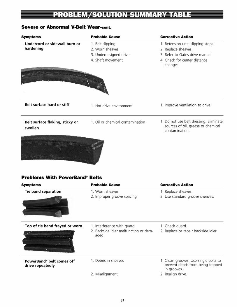
PROBLEM/SOLUTION SUMMARY TABLE
41
Symptoms
Undercord or sidewall burn or hardening
Belt surface hard or stiff
Belt surface flaking, sticky or
swollen
Probable Cause
1 . Belt slipping2 . Worn sheaves3 . Underdesigned drive4 . Shaft movement
1 . Hot drive environment
1 . Oil or chemical contamination
Corrective Action
1 . Retension until slipping stops .2 . Replace sheaves .3 . Refer to Gates drive manual .4 . Check for center distance
changes .
1 . Improve ventilation to drive .
1 . Do not use belt dressing . Eliminate sources of oil, grease or chemical contamination .
Severe or Abnormal V-Belt Wear–cont.
Problems With PowerBand® BeltsSymptoms
Tie band separation
Top of tie band frayed or worn
PowerBand® belt comes off drive repeatedly
Probable Cause
1 . Worn sheaves2 . Improper groove spacing
1 . Interference with guard2 . Backside idler malfunction or dam-
aged
1 . Debris in sheaves
2 . Misalignment
Corrective Action
1 . Replace sheaves .2 . Use standard groove sheaves .
1 . Check guard .2 . Replace or repair backside idler
1 . Clean grooves . Use single belts to prevent debris from being trapped in grooves .
2 . Realign drive .

PROBLEM/SOLUTION SUMMARY TABLE
42
Problems with V-Belt Take-Up
Symptoms
Multiple belts stretch unequally
Single belt, or where all belts stretch evenly
Belts do not match
Probable Cause
1 . Misaligned drive2 . Debris in sheaves3 . Broken tensile member or cord
damaged4 . Mismatched belt set
1 . Insufficient take-up allowance
2 . Grossly overloaded or under designed drive
3 . Broken tensile members
1 . Not all belts are from the same manufacturer
Corrective Action
1 . Realign and retension drive .2 . Clean sheaves .3 . Replace all belts, install properly .
4 . Install Gates matched belt set .
1 . Check take-up . Use allowance specified in Gates design manuals .
2 . Redesign drive .
3 . Replace belt, install properly .
1 . Use Gates belts
Symptoms
Involves single or multiple belts
Probable Cause
1 . Shock loading or vibration
2 . Foreign material in grooves3 . Misaligned sheaves
4 . Worn sheave grooves
5 . Damaged tensile member
6 . Incorrectly placed flat idler
7 . Mismatched belt set
8 . Poor drive design
Corrective Action
1 . Check drive design . Use Gates PowerBand® belts or Power Cable® belts .
2 . Shield grooves and drive .3 . Realign the sheaves .4 . Replace sheaves .5 . Use correct installation and belt
storage procedure .6 . Carefully align flat idler on slack
side of drive as close as possible to driveR sheaves .
7 . Replace with Gates matched belts . Do not mix old and new belts .
8 . Check for center distance stability and vibration dampening .
V-Belts Turn Over or Come Off Drive
Problems With PowerBand® Belts–cont.
Symptoms
One or more “ribs” runs out of pulley
Probable Cause
1 . Misalignment2 . Undertensioned
Corrective Action
1 . Realign drive .2 . Retension .

PROBLEM/SOLUTION SUMMARY TABLE
43
Problems With Sheaves
Symptoms
Broken or damaged sheave
Severe Groove Wear
Probable Cause
1 . Incorrect sheave installation
2 . Foreign objects falling into drive3 . Excessive rim speeds
4 . Incorrect belt installation
1 . Excessive belt tension2 . Sand, debris or contamination
3 . Wrong belt
Corrective Action
1 . Do not tighten bushing bolts beyond recommended torque values .2 . Use adequate drive guard .3 . Keep pulley rim speeds below
maximum recommended value .4 . Do not pry belts onto pulleys .
1 . Retension, check drive design .2 . Clean and shield drive as well as
possible .3 . Make sure belt and sheave combi-
nation is correct .
Unusual Vibration
Symptoms
Belts flopping
Unusual or excessive vibration
Probable Cause
1 . Loose belts (under tensioned)2 . Mismatched belts3 . Pulley misalignment
1 . Incorrect belt
2 . Poor machine or equipment design
3 . Pulley out of round4 . Loose drive components
Corrective Action
1 . Retension .2 . Install Gates matched belts .3 . Align pulley
1 . Use correct belt cross section in pulley . Use correct tooth profile and pitch in sprocket .
2 . Check structure and brackets for adequate strength .
3 . Replace with non-defective pulley .4 . Check machine components and
guards, motor mounts, motor pads, bushings, brackets and framework for stability, adequate design strength, proper mainte-nance and proper installation .
V-Belt Noise
Symptoms
Belt squeals or chirps
Slapping Sound
Rubbing sound
Grinding sound
Unusually loud drive
Probable Cause
1 . Belt slip2 . Contamination
1 . Loose belts2 . Mismatched set3 . Misalignment
1 . Guard interference
1 . Damaged bearings
1 . Incorrect belt
2 . Incorrect Tension3 . Worn sheaves4 . Debris in sheaves
Corrective Action
1 . Retension .2 . Clean belts and sheaves .
1 . Retension .2 . Install matched belt set .3 . Realign pulleys so all belts share
load equally .
1 . Repair, replace or redesign guard .
1 . Replace, align & lubricate .
1 . Use correct belt size . Use correct belt tooth profile for sprockets on synchronous drive .
2 . Check tension and adjust3 . Replace sheaves4 . Clean sheaves, improve shielding,
remove rust, paint, or remove dirt from grooves .

PROBLEM/SOLUTION SUMMARY TABLE
Hot Bearings 1 . Worn grooves - belts bottoming and won’t transmit power until overtensioned*
2 . Improper tension
3 . Motor manufacturer’s sheave diameter recommendation not fol-lowed
4 . Bearing underdesigned5 . Bearing not properly maintained
6 . Sheaves too far out on shaft
7 . Belt Slippage
1 . Replace sheaves . Tension drive properly .
2 . Retension .
3 . Redesign using drive design manual .
4 . Check bearing design .5 . Align and lubricate bearing .
6 . Place sheaves as close as possible to bearings . Remove obstructions
7 . Retension .
Problem With Other Drive ComponentsSymptoms
Bent or broken shaft
Probable Cause
1 . Extreme belt overtension2 . Overdesigned drive*
3 . Accidental damage4 . Machine design error5 . Accidental damage to guard or
poor guard design6 . Pulley mounted too far away from
outboard bearing
Corrective Action
1 . Retension2 . Check drive design, may need to
use smaller or fewer belts .3 . Redesign drive guard .4 . Check machine design .5 . Repair, redesign for durability .
6 . Move pulley closer to bearing .
* Using too many belts, or belts that are too large, can severely stress motor or driveN shafts . This can happen when load requirements are reduced on a drive, but the belts are not redesigned accordingly . This can also happen when a drive is greatly overdesigned . Forces created from belt tensioning are too great for the shafts .
44
Synchronous Belt Problems
Symptoms
Unusual noise
Probable Cause
1 . Misaligned drive2 . Too low or high tension3 . Backside idler4 . Worn sprocket5 . Bent guide flange6 . Belt speed too high7 . Incorrect belt profile for sprocket 8 . Subminimal diameter 9 . Excessive load
Corrective Action
1 . Correct alignment .2 . Adjust to recommended value3 . Use inside idler .4 . Replace .5 . Replace .6 . Redesign drive .7 . Use proper belt/sprocket combina-
tion .8 . Redesign drive using larger diam-
eters .9 . Redesign drive for increased
capacity .
Synchronous Drive Symptoms
NOTE: Belt Failure Analysis poster #12975 available . Contact your Gates Representative .

PROBLEM/SOLUTION SUMMARY TABLE
45
Tensile Break 1 . Excessive shock load
2 . Subminimal diameter
3 . Improper belt handling and storage prior to installation (crimping)
4 . Debris or foreign object in drive
5 . Extreme sprocket run-out
1 . Redesign drive for increased capacity .
2 . Redesign drive using larger diam-eters .
3 . Follow proper storage and han-dling procedures .
4 . Remove objects and check guard .5 . Replace sprocket .
Belt Cracking 1 . Subminimal diameter
2 . Backside idler
3 . Extreme low temperature at start-up .4 . Extended exposure to harsh
chemicals5 . Cocked bushing/sprocket assembly
1 . Redesign drive using larger diam-eter .
2 . Use inside idler or increase diam-eter of backside idler .
3 . Pre-heat drive environment .4 . Protect drive .
5 . Install bushing per instructions .
Premature Tooth Wear 1 . Too low or high belt tension2 . Belt running partly off unflanged
sprocket3 . Misaligned drive4 . Incorrect belt profile for sprocket
5 . Worn sprocket6 . Rough sprocket teeth
1 . Adjust to recommended value .2 . Correct alignment .
3 . Correct alignment .4 . Use proper belt/sprocket combina-
tion .5 . Replace .6 . Replace sprocket .
Excessive Belt Edge Wear 1 . Damage due to handling2 . Flange damage3 . Belt too wide4 . Belt tension too low
5 . Rough flange surface finish
6 . Improper tracking7 . Belt hitting drive guard or
bracketry8 . Misalignment
1 . Follow proper handling instructions .2 . Repair flange or replace sprocket .3 . Use proper width sprocket .4 . Adjust tension to recommended
value .5 . Replace or repair flange (to elimi-
nate abrasive surface) .6 . Correct alignment .7 . Remove obstruction or use inside
idler .8 . Realign drive
Tension Loss 1 . Weak support structure2 . Excessive sprocket wear3 . Fixed (non-adjustable) centers
4 . Excessive debris5 . Excessive load
6 . Subminimal diameter
7 . Belt, sprocket or shafts running too hot
8 . Unusual belt degradation
1 . Reinforce structure .2 . Use alternate sprocket material .3 . Use inside idler for belt adjust-
ment .4 . Remove debris, check guard .5 . Redesign drive for increased
capacity .6 . Redesign drive using larger diam-
eters .7 . Check for conductive heat transfer
from prime mover .8 . Reduce ambient drive temperature
to 185°F maximum .
Symptoms Probable Cause Corrective Action
Synchronous Belt Problems–cont.

PROBLEM/SOLUTION SUMMARY TABLE
Tooth Shear 1 . Excessive shock loads
2 . Less than 6 teeth-in-mesh 3 . Extreme sprocket run-out 4 . Worn sprocket 5 . Backside idler 6 . Incorrect belt profile for the
sprocket 7 . Misaligned drive 8 . Belt undertensioned
1 . Redesign drive for increased capacity .
2 . Redesign drive .3 . Replace sprocket .4 . Replace .5 . Use inside idler6 . Use proper belt/sprocket combina-
tion .7 . Realign .8 . Adjust tension to recommended
value .
Belt Ratcheting 1 . Drive is undertensioned
2 . Excessive shock loads
3 . Drive framework not rigid
1 . Adjust tension to recommended value .
2 . Redesign drive for increased capacity .
3 . Reinforce system .
Land Area Worn 1 . Excessive tension
2 . Excessive sprocket wear
1 . Adjust tension to recommended value .
2 . Check sprocket condition . Replace if necessary .
Unusual Sprocket Wear 1 . Sprocket has too little wear resis-tance (i .e . plastic, aluminum, soft metals)
2 . Misaligned drive3 . Excessive debris4 . Excessive load
5 . Belt tension too low or high
6 . Incorrect belt profile
1 . Use alternate sprocket material .
2 . Correct alignment .3 . Remove debris, check guard .4 . Redesign drive for increased
capacity .5 . Adjust tension to recommended
value .6 . Use proper belt/sprocket combina-
tion .
46
Flange Failure 1 . Belt forcing flange off 1 . Correct alignment or properly secure flange to sprocket .
Symptoms Probable Cause Corrective Action
Synchronous Sprocket Problems
Premature Tooth Wear–cont. 7 . Damaged sprocket 8 . Sprocket not to dimensional specification 9 . Belt hitting drive bracketry or other structure 10 . Excessive load
11 . Insufficient hardness of sprocket material 12 . Excessive debris 13 . Cocked bushing/sprocket assembly
7 . Replace . 8 . Replace .
9 . Remove obstruction or use idler
10 . Redesign drive for increased capacity 11 . Use a more wear-resistant sprocket 12 . Remove debris, check guard . 13 . Install bushing per instructions .
Symptoms Probable Cause Corrective Action
Synchronous Belt Problems–cont.

PROBLEM/SOLUTION SUMMARY TABLE
47
Performance ProblemsSymptoms
Incorrect driveN speed
Probable Cause
1 . Design error
Corrective Action
1 . Use correct driveR/driveN sprocket size for desired speed ratio .
Rust and Corrosion 1 . Rust caused by high moisture conditions in the production area, or by the use of water-based cleaning solutions .
1 . Replace cast iron sprockets and bushings with stainless steel com-ponents .
2 . Replace cast iron sprockets with nickel plated sprockets .
Symptoms Probable Cause Corrective Action
Synchronous Sprocket Problems–cont.
Belt Tracking 1 . Belt running partly off unflanged sprocket
2 . Centers exceed 8 times small sprocket diameter
3 . Excessive belt edge wear
1 . Correct alignment .
2 . Correct parallel alignment to set belt to track on both sprockets . Flange both sprockets .
3 . Correct alignment .
Excessive Temperature (Belt, Bearing, Housing, Shafts, etc.)
1 . Misaligned drive2 . Too low or high belt tension
3 . Incorrect belt profile
1 . Correct alignment .2 . Adjust tension to recommended
value .3 . Use proper belt/sprocket combina-
tion .
Shafts Out of Sync 1 . Design error2 . Incorrect belt
1 . Use correct sprocket sizes .2 . Use correct belt with correct tooth
profile for grooves .
Vibration 1 . Incorrect belt profile for the sprocket
2 . Too low or high belt tension
3 . Bushing or key loose
1 . Use proper belt/sprocket combina-tion .
2 . Adjust tension to recommended value .
3 . Check and reinstall per instructions .
NOTE: Belt Failure Analysis poster #12975 available . Contact your Gates Representative .

MAINTENANCE TOOLS
48
The tools available to help troubleshoot drive problems range from the surprisingly simple to complicated . Following is a list of tools that can be used to effectively diagnose a problem . While Gates does not sell all of the items discussed in this section, the items are readily available from industrial instrumentation outlets throughout the United States .
Eyes, Ears & Nose
When troubleshooting a belt drive problem, stand back and observe the drive while it is in operation and at rest . Is there a warm rubber smell? Is there anything unusual about the way the belt travels around the drive? Is the drive frame flexing under load? Are there chirping, squealing or grinding noises? Is there an accumulation of dust or debris beneath the drive which might interfere with the belts?
Squirt Bottle With Soapy Water
When a belt drive is excessively noisy, the belt is often incor-rectly blamed . It is easy to eliminate the belt as the problem by spraying it with soapy water while it is running . If the noise goes away, or decreases, then the belt is part of the problem . If the same noise is still present, the problem is likely due to other drive components .
String
Variation in drive center distance, often caused by weak supporting structure, can cause problems from vibration to short belt life . To determine if center distance variation exists, turn off the drive and tightly tie a piece of string from the driveR to the driveN shaft . Start up the drive and note if the string stretches almost to the point of breaking, or goes slack . If either is the case, the problem could be center dis-tance variation . It is particularly important to observe the string right at drive start up when the loads are highest . String can also be used to check pulley alignment .
Belt & Sheave Groove Gauges
If a belt-to-sheave groove mismatch is suspected, English and metric belt and sheave groove gauges can be used to check dimensions . These also are handy for identify-ing a belt cross section for replacements and for checking sheave grooves for wear .
These gauges are available from the local Gates distributor .
English Gauge: Product No . 7401-0014 Metric Gauge: Product No . 7401-0013
Long Straight Edge
While V-belts can be somewhat forgiving of misalign-ment, this condition can still affect V-belt performance . Even slight misalignment can cause major problems on a synchronous drive . Use a long straight edge, made of wood, metal or any rigid material, to quickly check drive alignment . Simply lay the straight edge across the pulley faces and note the points of contact (or lack of contact) .
Design Flex® Pro™ and Design IQ™ Software
Gates design suite of engineering programs include inter-active support software and a user friendly interface for rapid data retrieval and smooth design work .
Both programs are available at www .gates .com/drivedesign .
NOTE: In some cases redesign of the drive is necessary . Gates Design Flex® Pro™ drive design software provides a quick, accurate and flexible method of correctly redesigning problem drives .

C
Belt Tension Testers
Improper belt tension, either too high or too low, can cause belt drive problems . An “experienced” thumb may be okay for ordinary drives, but for critical drives, Gates recommends using a tension gauge . Proper tension and installation can extend belt life and reduce costly downtime .
Several types of tension gauges are available .
A. Tension Tester (Product No. 7401-0076) Maximum deflection force: 30 lbs . For use with all small V-belt and Synchronous drives, including PowerBand® and Poly Chain® GT® Carbon™ belt drives .
B. Double Barrel Tension Tester (Product No. 7401-0075) Maximum deflection force: 66 lbs . For use with all multiple V-belt and large Synchronous drives, including PowerBand® and Poly Chain® GT® Carbon™ belt drives .
C. 5-Barrel Tension Tester (Product No. 7401-0079) Maximum deflection force: 165 lbs . for use with multiple V-belt and large Synchronous drives .
D. Krikit Gauge (Product No. 7401-0071) For use with Automotive V-belts up to and including 7/8" top width .Krikit II (Product No. 7401-0072) For use with Automotive V-ribbed belts up to 8 ribs in width .
E. Sonic Tension Meter Model 507C (Product No. 7420-0507)
For extremely accurate belt tension measuring, the Gates Sonic Tension Meter is an electronic device that measures the natural frequency of a free stationary belt span and instantly computes the static belt tension based upon the belt span length, belt width and belt type .
Features:
• Can be used for synchronous and V-belts .
• Uses sound waves instead of force/deflection .
• Results are repeatable with any operator .
• Portable, lightweight and easy to use .• Fast . Calculates tension in seconds .• Can be used in almost any environ-
ment .• Model 507C runs on two AAA
batteries .
Accessories:F. Flexible Sensor (Product No. 7420-0204)
G. Optional Inductive Sensor (Product No. 7420-0212)
H. Replacement Magnets for Inductive Sensor (Prod. No. 7420-1212, set of 10)
I. EZ Align® Laser Alignment Tool (Product No. 7420-1000 - Red Laser) (Product No. 7420-3000 - Green Laser)
• Compact design• Laser projects a line• Mirror reflects laser line, making it
easy to align shafts• Laser line is very easy to read on
targets• Includes a hard foam filled plastic
carrying case• Green laser is ideal for outdoor or
bright environment use .
MAINTENANCE TOOLS
49
DBA FE
G
I
H

Dial Indicator
Improperly mounted sheaves or out-of-round pulleys are sometimes the root of vibration or more severe problems . This device can be used to measure side-to-side sheave wobble or diameter varia-tion by holding it up to the sheave side-wall or top of the belt inside the pulley groove, respectively . IMPORTANT: Always turn off the machine before using the dial indicator . Rotate the drive by hand to make your measurements .
Infrared Pyrometer
The pyrometer accurately measures external belt temperatures and envi-ronmental temperatures .
Noise Meter
Use a noise meter to measure environ-mental and belt drive noise .
Strobe Tachometer
It is not always possible to see what is happening to a drive while it is in operation . This instrument visually stops the action to get a better idea of the dynamic forces affecting the drive . The strobe tachometer is best used after initial diagnosis of the problem because it helps pinpoint the cause . It will help identify such things as single or dual mode belt span vibration and frame flexure .
MAINTENANCE TOOLS
50

TECHNICAL INFORMATION
51
Table No. 1
Heavy-Duty V-Belt Section, Sheave Diameters and Standard Groove Angles
Table No. 2
Maximum Allowable Outside Diameters For Cast Iron Pulleys
Table No. 3
Depth hk Shaft Diameter (Inches) Width wk +0.015-0.000 (inches)* (Inches)
Up Through 7/16 (0.44) 3/32 (0.094) 3/64 (0.047)Over 7/16 ( 0.44) To and Incl. 9/16 ( 0.56) 1/8 (0.125) 1/16 (0.062)Over 9/16 ( 0.56) To and Incl. 7/8 ( 0.88) 3/16 (0.188) 3/32 (0.094)Over 7/8 ( 0.88) To and Incl. 1 1/4 ( 1.25) 1/4 (0.250) 1/8 (0.125)
Over 1 1/4 ( 1.25) To and Incl. 1 3/8 ( 1.38) 5/16 (0.312) 5/32 (0.156)Over 1 3/8 ( 1.38) To and Incl. 1 3/4 ( 1.75) 3/8 (0.375) 3/16 (0.188)Over 1 3/4 ( 1.75) To and Incl. 2 1/4 ( 2.25) 1/2 (0.500) 1/4 (0.250)Over 2 1/4 ( 2.25) To and Incl. 2 3/4 ( 2.75) 5/8 (0.625) 5/16 (0.312)
Over 2 3/4 ( 2.75) To and Incl. 3 1/4 ( 3.25) 3/4 (0.750) 3/8 (0.375)Over 3 1/4 ( 3.25) To and Incl. 3 3/4 ( 3.75) 7/8 (0.875) 7/16 (0.438)Over 3 3/4 ( 3.75) To and Incl. 4 1/2 ( 4.50) 1 (1.000) 1/2 (0.500)Over 4 1/2 ( 4.50) To and Incl. 5 1/2 ( 5.50) 1 1/4 (1.250) 5/8 (0.625)
Over 5 1/2 ( 5.50) To and Incl. 6 1/2 ( 6.50) 1 1/2 (1.500) 3/4 (0.750)Over 6 1/2 ( 6.50) To and Incl. 7 1/2 ( 7.50) 1 3/4 (1.750) 3/4 (0.750)Over 7 1/2 ( 7.50) To and Incl. 9 ( 9.00) 2 (2.000) 3/4 (0.750)Over 9 ( 9.00) To and Incl. 11 ( 11.00) 2 1/2 (2.500) 7/8 (0.875)Over 11 ( 11.00) To and Incl. 13 ( 13.00) 3 (3.000) 1 (1.000)
* Tolerance on Width, wk for widths up through 1/2’’ (0.500) . . . . . . . . . . . . . . . . . . . . . . . . . . . . . . . +0.002-0.000 For widths over 1/2’’ (0.500) through 1’’ (1.000) . . . . . . . . . . . . . . . . . . . . . . . . . . . . . . . . . . . . . . . +0.003-0.000 For widths over 1’’ (1.000) . . . . . . . . . . . . . . . . . . . . . . . . . . . . . . . . . . . . . . . . . . . . . . . . . . . . . . . +0.004-0.000
BeltSection
Sheave DatumDiameter(D.D.) (in.)
StandardGroove Angle
(± 0.20˚)
A, AX Up to 5.4 34
A, AX Over 5.4 38
B, BX Up to 7.0 34
B, BX Over 7.0 38
C, CX Up to 7.99 34
C, CX 8.0 to 12.0 36
C, CX Over 12.0 38
D Up to 12.99 34
D 13.0 to 17.0 36
D Over 17.0 38
E Up to 24.0 36
E Over 24.0 38
BeltSection
Sheave OutsideDiameter(O.D.) (in.)
StandardGroove Angle
(± 0.20˚)
3V, 3VX Up to 3.49 36
3V, 3VX 3.50 to 6.00 38
3V, 3VX 6.0 to 12.00 40
3V, 3VX Over 12.00 42
5V, 5VX Up to 9.99 38
5V, 5VX 10.00 to 16.0 40
5V, 5VX Over 16.00 42
8V Up to 15.99 38
8V 16.00 to 22.4 40
8V Over 22.4 42
MaximumShaftSpeed(RPM)
Maximum AllowablePulley
Diameter(in.)
600 41.4
870 28.5
1,160 21.4
1,400 17.7
1,600 15.5
1,750 14.2
2,000 12.4
2,400 10.3
2,800 8.8
3,000 8.3
3,450 7.2
4,000 6.2
4,500 5.5
5,000 5.0
7,500 3.31
10,000 2.48

NEMA MINIMUM DIAMETERS
52
The National Electric Manufacturers Association (NEMA) publishes recom-mendations for the minimum diameter of sheaves to be used on General Purpose electric motors . Purpose of the recommendations is to prevent the use of too small sheaves, which can result in shaft or bearing damage because belt pull goes up as sheave diameter goes down .
The NEMA Standard MG-1-14 .42, November 1978 shows minimum recommended sheave diameters as a function of frame number . The table below lists the NEMA frame assign-ments and minimum diameter recom-mendations according to the 1964 rerating program .
For other than the General Purpose AC motors (for example, DC motors, Definite Purpose motors, motors with special bearings or motors that are larger than those covered by the NEMA standard), consult the motor manufacturer for minimum sheave diameter recommendations . It is helpful to the manufacturer to include details of the application with your inquiry .
Electric Motor Framesand Minimum Sheave and Sprocket Diameters
Table No. 4
Horsepower at Synchronous Speed (rpm) Synchronous Belts Motor Shaft 3600 1800 1200 900 Min. Frame Dia. (3450) (1750) (1160) (870) Pitch Code (in) Dia. (in)
143T 0 .875 1-1/2 1 3/4 1/2 2 .0
145T 0 .875 2 — 3 1-1/2 — 2 1 3/4 2 .2
182T 1 .125 3 3 1-1/2 1 2 .2
182T 1 .125 5 — — — 2 .4
184T 1 .125 — — 2 1-1/2 2 .2
184T 1 .125 5 — — — 2 .2
184T 1 .125 7-1/2 5 — — 2 .7
213T 1 .375 7-1/2—10 7-1/2 3 2 2 .7
215T 1 .375 10 — 5 3 2 .7
215T 1 .375 15 10 — — 3 .4
254T 1 .625 15 — 7-1/2 5 3 .4
254T 1 .625 20 15 — — 4 .0
256T 1 .625 20-25 — 10 7-1/2 4 .0
256T 1 .625 — 20 — — 4 .0
284T 1 .875 — — 15 10 4 .0
284T 1 .875 — 25 — — 4 .0
286T 1 .875 — 30 20 15 4 .7
324T 2 .125 — 40 25 20 5 .4
326T 2 .125 — 50 30 25 6 .1
364T 2 .375 — — 40 30 6 .1
364T 2 .375 — 60 — — 6 .7
365T 2 .375 — — 50 40 7 .4
365T 2 .375 — 75 — — 7 .7
404T 2 .875 — — 60 — 7 .2
404T 2 .875 — — — 50 7 .6
404T 2 .875 — 100 — — 7 .7
405T 2 .875 — — 75 60 9 .0
405T 2 .875 — 100 — — 7 .7
405T 2 .875 — 125 — — 9 .5
444T 3 .375 — — 100 — 9 .0
444T 3 .375 — — — 75 8 .6
444T 3 .375 — 125 — — 9 .5
444T 3 .375 — 150 — — 9 .5
445T 3 .375 — — 125 — 10 .8
445T 3 .375 — — — 100 10 .8
445T 3 .375 — 150 — — 10 .8
445T 3 .375 — 200 — — 11 .9

53
*These RPM are for 50 cycle electric motors . # 9 .5 for Frame Number 444T .
Data in the white area of Table No . 6 are from NEMA Standard MG-1-14 .42, November 1978 . Data in the gray area are from MG-1-14 .43, January 1968 . Data in the ?? area are a composite of electic motor manufacturers data . They are generally conservative, and specific motors and bearings may permit the use of a smaller motor sheave . Consult the motor manufacturer . See Page ?? .
NEMA MINIMUM DIAMETERS
Table No. 5
NEMA Minimum Sprocket Diameters
Minimum Recommended Sprocket Outside Diameters for General Purpose Electric Motors
NEMA Minumum V-Belt Sheave DiametersTable No. 6 Table No. 7
Minimum Recommended Sheave Datum Diameters for General Purpose Electric Motors
Hi-Power® II V-Belts, Hi-Power II PowerBand Belts or Tri-Power® Molded Notch V-Belts.
Minimum Recommended Sheave Outside Diameters for General Purpose Electric Motors
Super HC® V-Belts, Super HC PowerBand® Belts, Polyflex® JB® Belts.
Motor Motor RPM (60 cycle and 50 cycle Electric Motors) Motor Horse- 575 690 870 1160 1750 3450 Horse- power 485* 575* 725* 950* 1425* 2850 power
1/2 — — 2.2 — — — 1/2 3/4 — — 2.4 2.2 — — 3/4 1 3.0 2.5 2.4 2.4 2.2 — 1 1 1/2 3.0 3.0 2.4 2.4 2.4 2.2 1 1/2 2 3.8 3.0 3.0 2.4 2.4 2.4 2 3 4.5 3.8 3.0 3.0 2.4 2.4 3 5 4.5 4.5 3.8 3.0 3.0 2.4 5 7 1/2 5.2 4.5 4.4 3.8 3.0 3.0 7 1/2 10 6.0 5.2 4.4 4.4 3.8 3.0 10 15 6.8 6.0 5.2 4.4 4.4 3.8 15 20 8.2 6.8 6.0 5.2 4.4 4.4 20 25 9.0 8.2 6.8 6.0 4.4 4.4 25 30 10.0 9.0 6.8 6.8 5.2 — 30 40 10.0 10.0 8.2 6.8 6.0 — 40 50 11.0 10.0 8.4 8.2 6.8 — 50 60 12.0 11.0 10.0 8.0 7.4 — 60 75 14.0 13.0 9.5 10.0 8.6 — 75 100 18.0 15.0 12.0 10.0 8.6 — 100 125 20.0 18.0 15.0 12.0 10.5# — 125 150 22.0 20.0 18.0 13.0 10.5 — 150 200 22.0 22.0 22.0 — 13.2 — 200 250 22.0 22.0 — — — — 250 300 27.0 27.0 — — — — 300
*These RPM are for 50 cycle electric motors . † 11 .0 for Frame Number 444T .
Data in the white area of Table No . 7 are from NEMA Standard MG-1-14 .42, November 1978 . Data in the gray area are from MG-1-14 .43, January 1968 . Data in the ?? area are a composite of electic motor manufacturers data . They are generally conservative, and specific motors and bearings may permit the use of a smaller motor sheave . Consult the motor manufacturer . See Page ?? .
Motor Motor RPM (60 cycle and 50 cycle Electric Motors) Motor Horse- 575 690 870 1160 1750 3450 Horse- power 485* 575* 725* 950* 1425* 2850 power
1/2 2.5 2.5 2.2 — — — 1/2 3/4 3.0 2.5 2.4 2.2 — — 3/4 1 3.0 2.5 2.4 2.4 2.2 — 1 1 1/2 3.0 3.0 2.4 2.4 2.4 2.2 1 1/2 2 3.8 3.0 3.0 2.4 2.4 2.4 2 3 4.5 3.8 3.0 3.0 2.4 2.4 3 5 4.5 4.5 3.8 3.0 3.0 2.6 5 7 1/2 5.2 4.5 4.4 3.8 3.0 3.0 7 1/2 10 6.0 5.2 4.6 4.4 3.8 3.0 10 15 6.8 6.0 5.4 4.6 4.4 3.8 15 20 8.2 6.8 6.0 5.4 4.6 4.4 20 25 9.0 8.2 6.8 6.0 5.0 4.4 25 30 10.0 9.0 6.8 6.8 5.2 — 30 40 10.0 10.0 8.2 6.8 6.0 — 40 50 11.0 10.0 9.0 8.2 6.8 — 50 60 12.0 11.0 10.0 9.0 7.4 — 60 75 14.0 13.0 10.5 10.0 9.0 — 75 100 18.0 15.0 12.5 11.0 10.0 — 100 125 20.0 18.0 15.0 12.5 11.5† — 125 150 22.0 20.0 18.0 13.0 — — 150 200 22.0 22.0 22.0 — — — 200 250 22.0 22.0 — — — — 250 300 27.0 27.0 — — — — 300
Data in the white area are from NEMA Standard MG-1-14-42, June 1972 . Figures in black area are from MG-1-43, January 1968 . The gray area is a composite of electric motor manufacturer data . They are generally conservative and specific motors and bearings may permit the use of a smaller motor sprocket . Consult the motor manufacturer .
NOTE: For a given horsepower and speed, the total belt pull is related to the motor sprocket size . As the size decreases, the total belt pull increases . Therefore, to limit the resultant load on motor and shaft bearings, NEMA lists minimum sprocket sizes for the vari-ous motors . The sprocket on the motor (DriveR sprocket) should be at least this large .
MotorHorsepower
Motor RPM (60 Cycle and 50 Cycle Electric Motors)
MotorHorsepower
575485•
690575•
870725•
1160950•
17501425•
34502850•
1/2 - - 2.0 - - - 1/23/4 - - 2.2 2.0 - - 3/41 2.7 2.3 2.2 2.2 2.0 - 1
1-1/2 2.7 2.7 2.2 2.2 2.2 2.0 1-1/22 3.4 2.7 2.7 2.2 2.2 2.2 23 4.1 3.4 2.7 2.7 2.2 2.2 35 4.1 4.1 3.4 2.7 2.7 2.2 5
7-1/2 4.7 4.1 4.0 3.4 2.7 2.7 7-1/210 5.4 4.7 4.0 4.0 3.4 2.7 1015 6.1 5.4 4.7 4.0 4.0 3.4 1520 7.4 6.1 5.4 4.7 4.0 4.0 2025 8.1 7.4 6.1 5.4 4.0 4.0 2530 9.0 8.1 6.1 6.1 4.7 - 3040 9.0 9.0 7.4 6.1 5.4 - 4050 9.9 9.0 7.6 7.4 6.1 - 5060 10.8 9.9 9.0 7.2 6.7 - 6075 12.6 11.7 8.6 9.0 7.7 - 75100 16.2 13.5 10.8 9.0 7.7 - 100125 18.0 16.2 13.5 10.8 9.5# - 125150 19.8 18.0 16.2 11.7 9.5 - 150200 19.8 19.8 19.8 - 11.9 - 200250 19.8 19.8 - - - - 250300 24.3 24.3 - - - - 300
*These RPM are for 50 cycle electric motors . # Use 8 .6 for Frame Number 444 T only .

Minimum Recommended Sprocket Sizes
Table No. 9
Minimum Recommended Sheave Diameter By Belt Cross Section
Table No. 8
MINIMUM RECOMMENDED DIAMETERS
54
Min Recommended Sprocket Size Belt Pitch (No. of Teeth)
PowerGrip® Timing
MXL 12 XL 12 L 12 H 14 XH 18 XXH 18 PowerGrip® HTD®
3M 12 5M 14 8M 22 14M 28 20M 34 PowerGrip® GT®2
2M 12 3M 16 5M 18 8M 22 14M 28 Poly Chain® GT® Carbon™
8M 22 14M 28 Synchro-Power® Polyurethane
MXL 10 XL 10 L 10 H 14 T2.5 12 T5 10 T10 16 T20 15 AT5 12 AT10 18 AT20 18 5mm HTD 10 8mm HTD 16 14mm HTD 28
Min Recommended Belt Datum Diameter Cross (Standard Groove) Section (in)
Classical V-Belts
AX 2.20 A 3.00 BX 4.00 B 5.40 CX 6.80 C 9.00 D 13.00 E 21.00 Min Recommended Belt Outside Diameter Cross (Standard Groove) Section (in)
Narrow V-Belts
3VX 2.20 3V 2.65 5VX 4.40 5V 7.10 8V 12.50 Light Duty V-Belts
2L 0.8 3L 1.5 4L 2.5 5L 3.5 Micro-V® Belts
J 0.8 L 3.00 M 7.00 Polyflex® JB® Belts
3M 0.67 5M 1.04 7M 1.67 11M 2.64

Minimum Recommended Idler Diameters
MINIMUM RECOMMENDED DIAMETERS
55
Table No. 10
Minimum Min. O.D. Grooved Min. O.D. Flat Inside Flat Inside Backside Belt Cross Section (grooves) Idler (in) Idler (in)
MXL PowerGrip Timing 12 1.00 0.50 XL PowerGrip Timing 12 2.50 1.00 L PowerGrip Timing 10 4.75 1.60 H PowerGrip Timing 14 6.38 2.88 XH PowerGrip Timing 18 11.00 6.38 XXH PowerGrip Timing 18 15.75 9.25 2M PowerGrip GT2 12 1.00 0.50 3M PowerGrip GT2 + HTD 12 1.50 0.75 5M PowerGrip GT2 + HTD 14 2.50 1.25 8M PowerGrip GT2 + HTD 22 4.00 2.80 14M PowerGrip GT2 + HTD 28 7.00 6.50 20M PowerGrip HTD 34 10.00 11.00 5M Poly Chain GT2 16 2.50 1.88 8M Poly Chain GT Carbon 25 4.00 3.00 14M Poly Chain GT Carbon 28 7.00 6.50
Minimum Min. O.D. Grooved Min. O.D. Flat Inside Flat Inside Backside Belt Cross Section (grooves) Idler (in) Idler (in)
Classical A 3.00 2.25 4.25 B 5.400 3.75 6.00 C 9.00 5.75 8.50 D 13.00 7.50 13.50 E 21.00 19.00 27.30 AX 2.20 --- 4.25 BX 4.00 --- 6.00 CX 7.00 --- 8.50 AA 3.00 2.25 --- BB 5.40 3.75 --- CC 9.00 5.75 ---SuperHC 3V 2.65 --- 4.25 5V 7.10 --- 10.00 8V 12.50 --- 17.50 3VX 2.20 --- 4.25 5VX 4.40 --- 10.00Predator CP 9.00 5.75 8.50 3VP 2.65 --- 4.25 5VP 7.10 --- 8.50 8VP 12.50 --- 17.50

Table No. 11
V-BeltNumber
Minimum Center Distance AllowanceFor Installation (inches)
Minimum Center Distance Allowance For Initial
Tensioning and Subsequent
Takeup (Inches)
3V/3VX 5V/5VX 8V All Cross Sections
Super HC® V-Belts
Super HC® PowerBand® Belt*
Super HC® V-BeltsSuper HC®
PowerBand® Belt*Super HC® V-Belts
Super HC® PowerBand® Belt*
All Types
Up To and Incl. 475 0.5 1.2 1.0Over 475 To and Incl. 710 0.8 1.4 1.0 2.1 1.2
Over 710 To and Incl. 1060 0.8 1.4 1.0 2.1 1.5 3.4 1.5
Over 1060 To and Incl. 1250 0.8 1.4 1.0 2.1 1.5 3.4 1.8Over 1250 To and Incl. 1700 0.8 1.4 1.0 2.1 1.5 3.4 2.2Over 1700 To and Incl. 2000 1.0 2.1 1.8 3.6 2.5
Over 2000 To and Incl. 2360 1.2 2.4 1.8 3.6 3.0Over 2360 To and Incl. 2650 1.2 2.4 1.8 3.6 3.2Over 2650 To and Incl. 3000 1.2 2.4 1.8 3.6 3.5
Over 3000 To and Incl. 3550 1.2 2.4 2.0 4.0 4.0Over 3550 To and Incl. 3750 2.0 4.0 4.5Over 3750 To and Incl. 5000 2.0 4.0 5.5Over 5000 To and Incl. 6000 2.0 4.0 6.0
*Also use these figures for individual Super HC V-Belts in deep groove sheaves .
INSTALLATION & TENSIONING ALLOWANCES
56
Minimum Center Distance Allowances for Belt Installation and Takeup
Minimum Center Distance Allowances for Belt Installation and Takeup
Table No. 12
V-BeltNumber
Minimum Center Distance AllowanceFor Installation (inches)
Minimum Center Distance Allowance For Initial
Tensioning and Subsequent
Takeup (Inches)
A B C D E All Cross Sections
Hi- Power II
and Tri-Power®
Molded Notch
V-Belts
Hi-Power II PowerBand
Belt*
Hi- Power II
and Tri-Power®
Molded Notch
V-Belts
Hi-Power II PowerBand
Belt*
Hi- Power II
and Tri-Power®
Molded Notch
V-Belts
Hi-Power II PowerBand
Belt*
Hi- Power II
and Tri-Power®
Molded Notch
V-Belts
Hi-Power II PowerBand
Belt*Hi-Power II
V-BeltsHi-Power II PowerBand
Belt*All Types
Up To and Incl. 35 0.75 1.20 1.00 1.50 1.00Over 35 To and Incl. 55 0.75 1.20 1.00 1.50 1.50 2.00 1.50Over 55 To and Incl. 85 0.75 1.30 1.25 1.60 1.50 2.00 2.00
Over 85 To and Incl. 112 1.00 1.30 1.25 1.60 1.50 2.00 2.50Over 112 To and Incl. 144 1.00 1.50 1.25 1.80 1.50 2.10 2.00 2.90 3.00Over 144 To and Incl. 180 1.25 1.80 2.00 2.20 2.00 3.00 2.50 3.40 3.50
Over 180 To and Incl. 210 1.50 1.90 2.00 2.30 2.00 3.20 2.50 3.50 4.00Over 210 To and Incl. 240 1.50 2.00 2.00 2.50 2.50 3.20 2.50 3.60 4.50Over 240 To and Incl. 300 1.50 2.20 2.00 2.50 2.50 3.50 3.00 3.90 5.00
Over 300 To and Incl. 390 2.00 2.70 2.50 3.60 3.00 4.00 6.00Over 390 2.50 2.90 3.00 4.10 3.50 4.40 1.5% of belt length
*Also use these figures for individual Hi-Power II and Tri-Power Molded Notch V-Belts in deep groove sheaves .
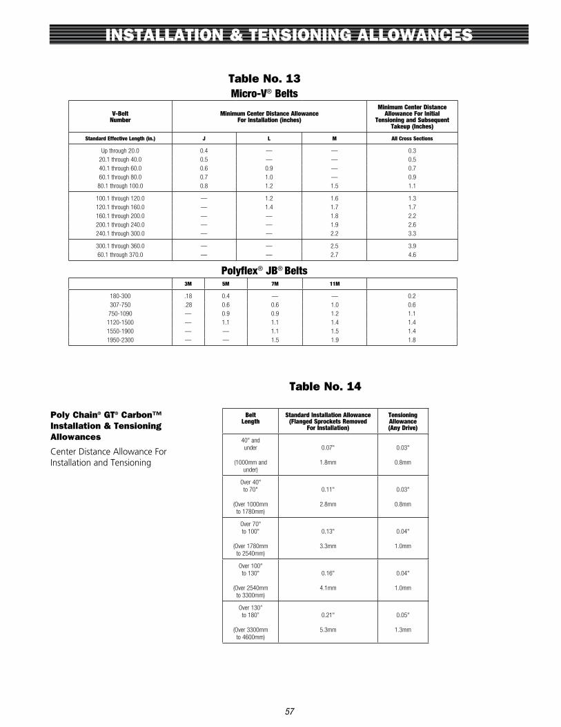
INSTALLATION & TENSIONING ALLOWANCES
57
Poly Chain® GT® Carbon™ Installation & Tensioning Allowances
Center Distance Allowance For Installation and Tensioning
Table No. 13Micro-V® Belts
V-BeltNumber
Minimum Center Distance AllowanceFor Installation (inches)
Minimum Center Distance Allowance For Initial
Tensioning and Subsequent Takeup (Inches)
Standard Effective Length (in.) J L M All Cross Sections
Up through 20.0 0.4 — — 0.320.1 through 40.0 0.5 — — 0.540.1 through 60.0 0.6 0.9 — 0.760.1 through 80.0 0.7 1.0 — 0.9
80.1 through 100.0 0.8 1.2 1.5 1.1
100.1 through 120.0 — 1.2 1.6 1.3120.1 through 160.0 — 1.4 1.7 1.7160.1 through 200.0 — — 1.8 2.2200.1 through 240.0 — — 1.9 2.6240.1 through 300.0 — — 2.2 3.3
300.1 through 360.0 — — 2.5 3.960.1 through 370.0 — — 2.7 4.6
Polyflex® JB® Belts3M 5M 7M 11M
180-300 .18 0.4 — — 0.2307-750 .28 0.6 0.6 1.0 0.6750-1090 — 0.9 0.9 1.2 1.11120-1500 — 1.1 1.1 1.4 1.41550-1900 — — 1.1 1.5 1.41950-2300 — — 1.5 1.9 1.8
Table No. 14
BeltLength
Standard Installation Allowance(Flanged Sprockets Removed
For Installation)
TensioningAllowance(Any Drive)
40" and under
(1000mm and under)
0.07"
1.8mm
0.03"
0.8mm
Over 40" to 70"
(Over 1000mm to 1780mm)
0.11"
2.8mm
0.03"
0.8mm
Over 70" to 100"
(Over 1780mm to 2540mm)
0.13"
3.3mm
0.04"
1.0mm
Over 100" to 130"
(Over 2540mm to 3300mm)
0.16"
4.1mm
0.04"
1.0mm
Over 130” to 180”
(Over 3300mm to 4600mm)
0.21"
5.3mm
0.05"
1.3mm

INSTALLATION & TENSIONING ALLOWANCES
58
Power Grip GT®2 and HTD Center Distance Allowance For Installation and Tensioning
Table No. 16
Table No. 17
Additional Center Distance allowance For Installation Over Flanged Sprockets*
(Add to Installation Allowance in Above Table)
Additional Center Distance Allowance For Installation Over Flanged Sprocket*
(Add to Installation Allowance in Above Table)
Table No. 15
BeltPitch One Sprocket Flanged
BothSprocketsFlanged
8mm 0.86" 1.31"8mm 21.8mm 33.3mm
14mm 1.23" 1.97"14mm 31.2mm 50.0mm
* For drives that require installation of the belt over one sprocket at a time, use the value for both sprockets flanged — even if only one sprocket is flanged.

INSTALLATION & TENSIONING ALLOWANCES
59
Power Grip® Timing Belts Center Distance Allowance for Installation and Tensioning
Additional Center Distance Allowance for Installation Over Flanged Pulleys*
(Add to Installation Allowance in Above Table)
Estimating Belt Length from Drive Dimensions
(2 Pulleys)
Table No. 18
BeltLength
(in.)
Standard Installation Allowance(Flanged Pulleys Removed
For Installation)
TensioningAllowance(Any Drive)
3.6 to 5.0 .02" .02"
Over 5.0 to 10.0
.03" .03"
Over 10.0 to 20.0
.04" .03"
Over 20.0 to 40.0
.05" .04"
Over 40.0 to 60.0
.07" .05"
Over 60.0 to 180.0
.12" .08"
Table No. 19
Belt Pitch Small Pulley Flanged Both Pulleys Flanged
0.080" (MXL) .33" .49"
0.200" (XL) .46" .71"
0.375" (L) .64" .85"
0.500" (H) .64" .96"
0.875" (XH) 1.14” 1.92"
1.250" (XXH) 1.53" 2.65"
* For drives that require installation of the belt over one sprocket at a time, use the value for both pulleys flanged — even if only one pulley is flanged.
Table No. 20
Belt Length = 2C + 1.57 (D + d) + (D - d)2
4C
Where: C = Shaft Center Distance
a.) For Super HC®: Belt Length = Belt Outside Diameter D = O.D. of Larger Pulley d = O.D. of Smaller Pulley
b.) For Hi-Power® II Belt Length = Datum Length and Tri-Power® D = Datum Diameter of Larger Pulley Molded Notch: d = Datum Diameter of Smaller Pulley
c.) For Synchronous Belt Length = Pitch Length Belts: D = Pitch Diameter of Larger Sprocket d = Pitch Diameter of Smaller Sprocket

IDLER HARDWARE
60
Idlers are used to take-up extra belt length and provide adjustment for tensioning belt drives. Idler pulleys andsprockets can alter belt paths and clear obstructions.
Markets/ApplicationsRecommended for drives with limited take-up or no center distance adjustment. Idlers may remain in a fixedlocation or may be adjustable to allow belt pre-tension take-up.
Features/Advantagesn Idler sprockets, flat idlers and idler bushings contain sealed ball bearings and an integral shaft for mounting to
adjustable idler brackets.n Lubrication and maintenance are not required.n Idler assembly may consist of: idler sprocket and bracket, flat idler and bracket, standard sheave or sprocket
used with an idler bearing and idler bracket.
Flat Idler Pulley
PartNo.
ProductNo.
Use with Synchronous Belt
Use with V-BeltOutsideDia. (In.)
FaceWidth
(In) A B C D E ThreadsBearingNumber
Wt.Ea.
(Lbs.)Pitch Width
4.25X1.25-IDL-FLAT7723-41258mm, L, HUp to 21mm (0.85")1-2 Strand 3V/3VX,1 Strand A/AX
4.25 1.25 1.131.13 .64 1.30 3.75 3/4-16 6304 5.20
4.25X2.00-IDL-FLAT7723-42008mm, L, H Up to 38mm (1.5") 3-4 Strand 3V/3VX,2 Strand A/AX
4.25 2.00 1.501.13 .63 1.32 4.50 3/4-16 6304 7.50
4.25X3.00-IDL-FLAT7723-43008mm, L, H Up to 62mm (2.4") 5-6 Strand 3V/3VX,3 Strand A/AX
4.25 3.00 1.501.13 .75 1.32 5.63 3/4-16 6304 10.60
4.25X4.00-IDL-FLAT7723-44008mm, L, H Up to 85mm (3.3") 8 Strand 3V/3VX,4 Strand A/AX
4.25 4.00 1.501.13 .75 1.32 6.63 3/4-16 6304 13.60
6.50X1.75-IDL-FLAT7723-6175 14mm Up to 20mm 1 Strand B/BX 6.50 1.75 2.001.501.041.96 5.69 1-14 6308 17.106.50X2.75-IDL-FLAT7723-6275 14mm Up to 55mm 2-3 Strand B/BX 6.50 2.75 2.001.50 .13 2.10 5.69 1-14 6308 23.006.50X4.25-IDL-FLAT7723-6425 14mm Up to 90mm 4-5 Strand B/BX 6.50 4.25 2.381.50 .13 1.98 7.06 1-14 6308 33.006.50X5.75-IDL-FLAT7723-6575 14mm Up to 125mm 6 Strand B/BX 6.50 5.75 2.381.50 .99 1.98 9.31 1-14 6308 45.006.50X7.50-IDL-FLAT7723-6750 14mm Up to 170mm 8 Strand B/BX 6.50 7.50 2.381.501.001.9811.19 1-14 6308 57.01
GATES INDUSTRIAL BELT PRODUCTS June 2012
Flat Idler Pulley
IDLERS
® Powering Progress. gates.com/pt 259
Idlers are used to take-up extra belt length and provide adjustment for tensioning belt drives. Idler pulleys andsprockets can alter belt paths and clear obstructions.
Markets/ApplicationsRecommended for drives with limited take-up or no center distance adjustment. Idlers may remain in a fixedlocation or may be adjustable to allow belt pre-tension take-up.
Features/Advantagesn Idler sprockets, flat idlers and idler bushings contain sealed ball bearings and an integral shaft for mounting to
adjustable idler brackets.n Lubrication and maintenance are not required.n Idler assembly may consist of: idler sprocket and bracket, flat idler and bracket, standard sheave or sprocket
used with an idler bearing and idler bracket.
Flat Idler Pulley
PartNo.
ProductNo.
Use with Synchronous Belt
Use with V-BeltOutsideDia. (In.)
FaceWidth
(In) A B C D E ThreadsBearingNumber
Wt.Ea.
(Lbs.)Pitch Width
4.25X1.25-IDL-FLAT7723-41258mm, L, HUp to 21mm (0.85")1-2 Strand 3V/3VX,1 Strand A/AX
4.25 1.25 1.131.13 .64 1.30 3.75 3/4-16 6304 5.20
4.25X2.00-IDL-FLAT7723-42008mm, L, H Up to 38mm (1.5") 3-4 Strand 3V/3VX,2 Strand A/AX
4.25 2.00 1.501.13 .63 1.32 4.50 3/4-16 6304 7.50
4.25X3.00-IDL-FLAT7723-43008mm, L, H Up to 62mm (2.4") 5-6 Strand 3V/3VX,3 Strand A/AX
4.25 3.00 1.501.13 .75 1.32 5.63 3/4-16 6304 10.60
4.25X4.00-IDL-FLAT7723-44008mm, L, H Up to 85mm (3.3") 8 Strand 3V/3VX,4 Strand A/AX
4.25 4.00 1.501.13 .75 1.32 6.63 3/4-16 6304 13.60
6.50X1.75-IDL-FLAT7723-6175 14mm Up to 20mm 1 Strand B/BX 6.50 1.75 2.001.501.041.96 5.69 1-14 6308 17.106.50X2.75-IDL-FLAT7723-6275 14mm Up to 55mm 2-3 Strand B/BX 6.50 2.75 2.001.50 .13 2.10 5.69 1-14 6308 23.006.50X4.25-IDL-FLAT7723-6425 14mm Up to 90mm 4-5 Strand B/BX 6.50 4.25 2.381.50 .13 1.98 7.06 1-14 6308 33.006.50X5.75-IDL-FLAT7723-6575 14mm Up to 125mm 6 Strand B/BX 6.50 5.75 2.381.50 .99 1.98 9.31 1-14 6308 45.006.50X7.50-IDL-FLAT7723-6750 14mm Up to 170mm 8 Strand B/BX 6.50 7.50 2.381.501.001.9811.19 1-14 6308 57.01
GATES INDUSTRIAL BELT PRODUCTS June 2012
Flat Idler Pulley
IDLERS
® Powering Progress. gates.com/pt 259Idler Bushings
PartNo.
ProductNo. Style Size
D(In)
L(In)
M(In) Threads
BearingNumber
Wt.Ea.
(Lbs.)
20-IDLR-BUSH(SK) 7720-1120 20 SK 2.81 1.94 1.44 3/4-16 6003 11.0030-IDLR-BUSH(SF) 7720-1130 20 SF 3.13 2.08 2.13 1-14 6204 8.6040-IDLR-BUSH(E) 7720-1140 20 E 3.83 2.75 2.19 1-14 6304 8.621610-IDLR-BUSH 7720-2610 20 1610 2.25 1.00 1.38 5/8-18 6304 1.302012-IDLR-BUSH 7720-2012 20 2012 2.75 1.25 1.56 3/4-16 6206 2.302517-IDLR-BUSH 7720-2517 20 2517 3.38 1.75 1.56 3/4-16 6306 3.90
GATES INDUSTRIAL BELT PRODUCTS June 2012
Idler Bushings
IDLE
RS
®gates.com/pt Gates Corporation262

IDLER HARDWARE
61
Poly Chain® GT® Carbon™ Idler Sprocket
PartNo.
ProductNo. Use With
BeltWidth
No. ofTeeth
OutsideDia. (In.)
B Ref.(In)
C(In)
D(In)
E Ref.(In)
F(Threads)
(In)
GRef.(In)
H(In)
J(In)
BearingNumber
Wt.Ea.
(Lbs.)
12-IDL-SPRK 7720-1500 8mm Pitch 12 32 3.145 1.25 .50 .85 1.56 3/4 - 16 .94 2.75 — 6304 3.8021-IDL-SPRK 7720-1510 8mm Pitch 21 32 3.145 1.25 .50 1.24 1.56 3/4 - 16 .56 2.75 — 6304 3.8836-IDL-SPRK 7720-1520 8mm Pitch 36 36 3.546 1.91 .75 1.86 1.63 3/4 - 16 — — — 6306 5.1462-IDL-SPRK 7720-1530 8mm Pitch 62 36 3.546 1.91 .75 2.91 1.69 3/4 - 16 .69 3.13 — 6306 9.6920-IDL-SPRK 7720-1600 14mm Pitch 20 30 5.153 2.55 1.00 1.36 2.25 1 - 14 1.00 4.38 — 6308 12.5537-IDL-SPRK 7720-1610 14mm Pitch 37 30 5.153 2.55 1.00 2.06 2.25 1 - 14 .25 4.38 — 6308 13.4668-IDL-SPRK 7720-1620 14mm Pitch 68 34 5.855 3.38 .56 3.33 2.25 1 - 14 1.00 4.88 4.34 6310 26.0390-IDL-SPRK 7720-1640 14mm Pitch 90 34 5.855 3.38 .31 4.20 2.25 1 - 14 1.00 4.88 4.34 6310 32.18125-IDL-SPRK 7720-1630 14mm Pitch 125 34 5.855 3.38 .19 5.63 2.25 1 - 14 1.09 4.88 4.34 6310 36.45
Nickel Plate Poly Chain® GT® Carbon™ IdlerSprocket
PartNo.
ProductNo. Use With
BeltWidth
No. ofTeeth
OutsideDia. (In.)
B Ref.(In)
C(In)
D(In)
E Ref.(In)
F(Threads)
(In)
GRef.(In)
H(In)
J(In)
Wt.Ea.
(Lbs.)
NP-12-IDLR-SPRK 7720-1501 8mm Pitch Poly Chain GT Carbon — 32 3.145 1.25 .50 .85 1.56 3/4 - 16 .94 2.75 — 3.80NP-21-IDLR-SPRK 7720-1511 8mm Pitch Poly Chain GT Carbon — 32 3.145 1.25 .50 1.24 1.56 3/4 - 16 .56 2.75 — 3.88
PowerGrip® GT®2 Idler Sprocket
PartNo.
ProductNo. Use With
BeltWidth
No. ofTeeth
OutsideDia. (In.)
B Ref.(In)
C(In)
D(In)
E Ref.(In)
F(Threads)
(In)
GRef.(In)
H(In)
J(In)
BearingNumber
Wt.Ea.
(Lbs.)
20-SPK2-IDL 7720-1740 8mm Pitch 20 32 3.154 1.25 .50 1.24 1.56 3/4 - 16 .56 2.75 — 6304 1.1030-SPK2-IDL 7720-1750 8mm Pitch 30 36 3.555 1.91 .75 1.86 1.63 3/4 - 16 — — — 6306 2.0040-SPK2-IDL 7720-1850 14mm Pitch 40 30 5.153 2.55 1.00 2.06 2.25 1 - 14 .25 4.38 — 6308 12.0055-SPK2-IDL 7720-1860 14mm Pitch 55 34 5.855 3.38 .56 3.33 2.25 1 - 14 1.00 4.88 4.34 6310 15.60
GATES INDUSTRIAL BELT PRODUCTS June 2012
Idler Sprockets
IDLE
RS
®gates.com/pt Gates Corporation260

62
IDLER HARDWARE
Idler Brackets
PartNo.
TensionerPart No. Use With
A(In)
B(In)
C(In)
D(In)
E(In)
F(In)
G(In)
H(In)
J(In)
M(Threads)
N(In)
P(In)
Q(In)
Wt.Ea.
(Lbs.)
5-IDL-BRAK 7720-1005 1610-IDL-BUSH 4.62 3.50 1.75 2.00 2.06 3.06 .38 1.63 .62 5/8 - 18 1.16 2.01 2.00 2.8010-IDL-BRAK 7720-1010 8mm Pitch Idler Sprockets,
4.25" OD Flat Idler Pulleys,2012-IDL-BUSH,2517-IDL-BUSH,
20-IDL-BUSH (SK)
4.63 3.50 1.75 2.00 2.06 3.06 .38 1.50 .56 3/4 - 16 1.00 1.88 1.75 3.40
20-IDL-BRAK 7720-1020 14mm Pitch Idler Sprockets,6.50" OD Flat Idler Pulleys,
30-IDL-BUSH (SF),40-IDL-BUSH (E)
6.94 5.25 2.63 5.00 3.00 4.56 .63 2.38 1.00 1 - 14 1.63 2.94 2.75 11.20
Nickel Plated Idler Brackets
PartNo.
TensionerPart No. Use With
A(In)
B(In)
C(In)
D(In)
E(In)
F(In)
G(In)
H(In)
J(In)
M(Threads)
N(In)
P(In)
Q(In)
Wt.Ea.
(Lbs.)
NP-10-IDLR-BRACKET 7720-1011 8mm Pitch Idler Sprockets2012-IDL-BUSH,2517-IDL-BUSH,
20-IDL-BUSH (SK)
4.63 3.50 1.75 2.00 2.06 3.06 .38 1.50 .56 3/4 - 16 1.00 1.88 1.75 3.40
NP-20-IDLR-BRACKET 7720-1021 14mm Pitch Idler Sprockets,30-IDL-BUSH (SF),40-IDL-BUSH (E)
6.94 5.25 2.63 5.00 3.00 4.56 .63 2.38 1.00 1 - 14 1.63 2.94 2.75 11.20
GATES INDUSTRIAL BELT PRODUCTS June 2012
Idler Brackets
IDLERS
® Powering Progress. gates.com/pt 261

DRIVE SURVEY WORKSHEET
High Speed Drive Survey and Energy Savings Worksheet
CUSTOMER INFORMATION
Distributor _________________________________________________________________________________________________
Customer __________________________________________________________________________________________________
DRIVE INFORMATION
I.D. of Drive (location, number, etc .) ___________________________________________________________________________
Description of DriveN Equipment ___________________________________________________________________________
Manufacturer of DriveN Equipment _________________________________________________________________________
Horsepower Rating of Motor _______________ DriveN HP Load (Peak) _________________ (Normal) ______________
Motor Frame Size _______________ Motor Shaft Dia . _______________ DriveN Shaft Dia . ___________________
Speed:
DriveR RPM _______________ ___________________ RPM Measured with Contact or Strobe Tachometer Yes No
DriveN RPM _______________ __________________ RPM Measured with Contact or Strobe Tachometer Yes No
Speed Ratio _______________ Speed Up _______________________ or Speed Down ___________________
Center Distance: Minimum _______________ Nominal ____________________ Maximum ________________________
Existing Drive Components: DriveR _______________________________ DriveN _______________________________
Belts ________________________________________ Belt Manufacturer _____________________________________
Ambient Conditions:
Temperature _________________ Moisture _____________________ Oil, etc . _______________________________
Abrasives __________________________________________________ Shock Load ___________________________
Static Conductivity Required? Yes No
Maximum Sprocket Diameter (OD) and Width Limitations (for guard clearance):
DriveR: Max . OD __________ Max . Width ___________ DriveN: Max . OD ___________ Max . Width ____________
Guard Description _______________________________________________________________________________________
Motor Mount:
Double Screw Base? Yes No Motor Mounted on Sheet Metal? Yes No
Adequate Structure? Yes No Floating/Pivot Motor Base? Yes No
Start Up Load:
%Motor Rating at Start Up __________ AC Inverter? Yes No Soft Start? Yes No
Duty Cycle:
Number of Starts/Stops _________________________ times per _______________________ (hour, day, week, etc .)
ENERGY SAVINGS INFORMATION
Energy Cost per KW-Hour __________________________________________________________________________________
Hours of Operation: ______ Hours per Day ______ Days per Week ______ Weeks per Year
63

DRIVE SURVEY WORKSHEET
62
Distributor: Drive LayoutCustomer: (check one)
Drive Identification (location, number, etc.)
DriveR Information:
Motor Nameplate Data
Rated Horsepower = Efficiency =
Rated Voltage = Rated Torque =
Actual Motor Load =
Motor Type: DC Gear Motor
Output Speed:
Reducer Information:
Reducer Type (worm, right angle helical, cycloidal, etc):
Output RPM = Reducer Ratio =
Existing Drive Information:
Chain V-Belt Synchronous Belt
Lubed
(teeth/OD) DriveR Shaft Diameter =
(teeth/OD) DriveN Shaft Diameter =
+ -
Type of Center Distance Adjustment:
Yes No Inside Backside
DriveN Information:
Type of Equipment: Actual Horsepower Required =
DriveN RPM =
Hours/Day = Days/Week = Weeks/Year =
Special Requirements:
Space Limitations:
Maximum DriveR Dia. = Maximim DriveN Dia =
Maximum DriveR Width = Maximum DriveN Width =
Environmental Conditions:
Temperature Range = Belt Conductivity Required
Oil Mist Oil Splash Moisture Abrasives
Unlubed
For Drive Selections with Shaft Speeds Less Than 500 rpm
Motor Reducer Belt Drive Driven
Rated RPM =
Rated Amps =
AC
Constant Variable
Reducer Efficiency =
Rated Input HP/Torque = Rated Output HP/Torque =
Drive Type:
If chain, type; 2/#60. #80, etc.
Current Drive Service Life =
DriveR Sprocket/Sheave =
Idler used:
DriveN Sprocket/Sheave =
Center Distance =
Motor Belt Drive Reducer Driven
Belt Drive on Reducer Input Shaft
Belt Drive on Reducer Output Shaft
Low Speed Drive Design Information Sheet
DRIVE SURVEY WORKSHEET
64
Low Speed Drive Design Information Sheet
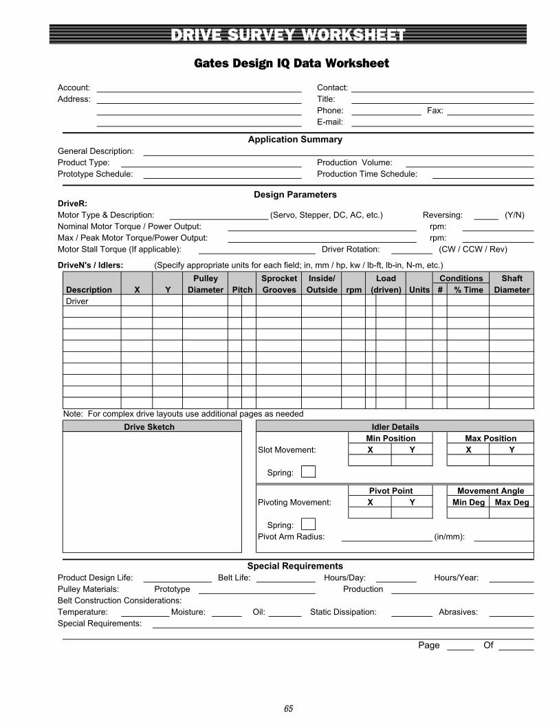
DRIVE SURVEY WORKSHEET
63
Account: Contact:Address: Title:
Phone: Fax: E-mail:
General Description:Product Type: Production Volume:Prototype Schedule: Production Time Schedule:
DriveR:Motor Type & Description: (Servo, Stepper, DC, AC, etc.) Reversing: (Y/N)Nominal Motor Torque / Power Output: rpm:Max / Peak Motor Torque/Power Output: rpm:Motor Stall Torque (If applicable): Driver Rotation: (CW / CCW / Rev)
DriveN's / Idlers: (Specify appropriate units for each field; in, mm / hp, kw / lb-ft, lb-in, N-m, etc.)
#Driver
Note: For complex drive layouts use additional pages as needed
Slot Movement:
Spring:
Pivoting Movement:
Spring: Pivot Arm Radius: (in/mm):
Product Design Life: Belt Life: Hours/Day: Hours/Year:Pulley Materials: Prototype ProductionBelt Construction Considerations:Temperature: Moisture: Oil: Static Dissipation: Abrasives:Special Requirements:
Page Of
XMin Position Max Position
X YInside/
(driven) % Time
Drive Sketch Idler Details
rpm UnitsDescription OutsideDiameter Pitch Grooves Diameter
Application Summary
Design Parameters
Pulley Sprocket Load Conditions Shaft
Special Requirements
Y
Pivot Point Movement AngleX Y Min Deg Max Deg
X Y
Gates Design IQ Data Worksheet
DRIVE SURVEY WORKSHEET
65
Gates Design IQ Data Worksheet

TRADEMARKS
WARRANTY
66
• HT100®, Taper−Lock® and Ringfeder® are registered trademarks of Reliance Electric .
• Nu−T−Link® is a registered trademark of Fenner Manheim .
• QD® is a registered trademark of Emerson Electric .
• RPP® and Panther® are registered trademarks of Carlisle Power Transmission Products, Inc .
• KEVLAR® is a registered trademark of E . I . du Pont de Nemours and Company .
• Goodyear®, BlackHawk PdTM, Poly−V® and Flexten® are registered trademarks of Goodyear Tire & Rubber Company .
• Browning® is a registered trademark of Emerson Power Transmission Manufacturing L .P .
• Dayco® is a registered trademark of Dayco Products LLC .
• TB Wood’s® and QT Power Chain® are registered trademarks of T .B . Wood’s, Inc .
• Trantorque® is a registered trademark of BTL, a subsidiary of Fenner PLC
Gates warrants that its power transmission products will be free from defects in materials andworkmanship for the life of the product . If the product does not meet this standard, Gates will repair or replace the product free of charge!
Please note that this warranty is customer’s exclusive remedy and does not apply in the event of misuse or abuse of the product . Gates disclaims all other warranties (express or implied) including the implied warranties of fitness for a particular purpose and merchantability .
For further details of the Gates Warranty, please see www .gates .com/warranty .