Embed Size (px)
Citation preview

Behavior of Welded PlateConnections in Precast ConcretePanels Under SimulatedSeismic Loads
Christian 1. Hofheins, P.E.Engineer
JM Williams and AssociatesSalt Lake City, Utah
Lawrence D. Reaveley,Ph.D., RE.ProfessorDepartment of Civil &Environmental EngineeringUniversity of UtahSalt Lake City, Utah
Chris P. Pantelides,Ph.D., P.E.
ProfessorDepartment of Civil &
Environmental EngineeringUniversity of Utah
Salt Lake City, Utah
Tests were performed on precast wall panels withtypical loose-plate connectors located in thevertical joint between panels. The tests wereperformed to investigate the performance of theconnectors under simulated seismic loads. In-plane lateral cyclic loads were applied to the wallpanels, which applied tension-shear andcompression-shear forces to the loose-plateconnectors. The paper describes the experimentalprogram and results for the welded plateconnections in ten precast concrete wall panelassemblies. Design assumptions and simplifieddesign models are also examined. The researchshows that the connection possesses little ductilecapacity and, therefore, is not suitable for use inhigh seismic regions (Zones 3 and 4). However,based on the observed failure modes, minormodifications to the connection are suggested thatwill increase the ductility of the connection.
This paper addresses the behavior of a specific loose-plate welded connector under applied cyclic loading.This type of connection is widely used in the United
States. Due to the limited number of tests performed, nospecific design parameters were considered in this study.
The objectives of this investigation were to:(a) Quantify the performance of the connection in terms
of force-deflection and ductility.(b) Check the validity of design values that are currently
used for loose-plate welded connections in hollow-coreprecast concrete wall panel construction.
122 PCI JOURNAL

8-0” NOMINAL
1, -5” 1- 3.5 .. 1’ -5”
1 1 TYPICAL
(10) 1/2” DIA 270 K STRAND
Fig. 1. Details ofhollow-corewall panel.Note: 1 ft = 0.3408 m.
(c) Model the connection and provide preliminary recommendationsbased on observed failure modes.
Precast concrete has largely beenused in parts of the world where seismic issues play a small role in design.As a result, many common precastconcrete connections are generally notdesigned to provide the desired ductility in seismic resistant structures.
Presently, there is not an adequateset of seismic code requirements forthe design of loose-plate connectionsin precast wall panels. Most loose-plate connections currently specifiedby engineers are designed with staticmodels that are not supported by testdata.
The design of precast connectionsfor high seismic areas must addressthe need for design strength, displacement ductility, or both. One strategy isto design a ductile connection that isweaker than the precast concrete wallpanels. This enables the connection tobe at a location of ductile inelastic deformation and the precast wall panelsto remain elastic under seismic response.
As a result, overall costs decreasebecause the precast concrete wall panels do not need to be designed for ductility. Ductile connections allow lateralforces to be redistributed to all connectors. Another attractive feature ofthis system is that some ductile connections can be replaced after a seismic event, resulting in considerablesavings in repair costs.
A loose-plate connection typicallycomprises a steel plate welded to steelembeds cast into the concrete. Themajority of loose-plate connectionsused in current practice have not beensubjected to thorough testing. Consequently, there is little experimental
validation upon which design procedures can be based.
Most precast connectors were developed through field experience by individual precast manufacturers. Theseconnectors are not supported by sufficient test data to determine theirstrength and deformation capacity.
Standard test methods may be required in the future, because designcodes will likely define design criteriain terms of performance objectives. Aperformance objective is the combination of a specific seismic hazard and adesired performance level. In this scenario, all components of a structurewill be required to undergo rigoroustesting to determine its performancelevel.
LITERATURE REVIEWDuring the last 40 years, several
studies have been carried out on a variety of wet and dry precast wall panelconnections. A wet connection ismade by cast-in-place concrete between the precast concrete panels; adry connection consists of steel embedded plates, angles, or other steel elements that are welded together by asteel plate.
The continuity of precast, prestressed double tee floors was investigated in a series of tests.1 Intermediategrade deformed bars were placedacross the supports, and concrete wasplaced in the space between adjacentends of the double tees to form transverse diaphragms. The primary objective was to investigate the structuralsoundness of the continuity connection, which was found to be adequate.
Additional testing was performed todetermine the flexural resistance ofcast-in-place insulated walls. Three
types of metal shear connectors between the concrete shells were included: a truss, a ladder, and an expanded metal shear connector. Thetruss and ladder shear connectors werefound to be satisfactory.2
A variety of wet joints were studiedto determine their ultimate shearstrength.3 The research proved thatwet joints used for vertical joints inpanel structures effectively resist highshear forces. Although the joint installation is labor intensive, the joint canbe very ductile if properly designed.
Originally, dry joints were mostlycomposed of headed studs welded tothe back of a steel plate. In one suchheaded stud connection,4it was foundthat shear loads are transmittedthrough the embedded plate to the surrounding concrete by three distinctmechanisms:
(a) Friction between the embeddedplate and concrete.
(b) Bearing of the end of the embedded plate on concrete.
(c) Interaction between studs andconcrete.
These headed stud connections provide good shear resistance, but have alow ductile capacity.
The PCI-sponsored Precast SeismicStructural Systems (PRESSS) researchprogram has taken the lead on research and design recommendationsfor precast concrete structures in areasof high seismicity. Among other topics, the PRESSS program has performed research on a variety ofwelded connections for precast wallsystems. The initial goal of the research was to develop ways of classifying and evaluating connection details.5
The National Institute for Standardsand Technology (NIST) investigated
July-August 2002 123

the seismic performance of horizontaland vertical joint connections in precast walls.6 The connections were designed to be ductile, and to be themajor location of inelastic response ofthe structure. Vertical joint connections included different designs ofwelded loose-plate and bolted ductileconnections. The connections took advantage of the interaction between theembed and concrete by incorporatingflexural yield, tension/compressionyield, shear yield and friction slidingconcepts.
The behavior of a six-story precastconcrete office building under moderate seismicity was investigated.7Itwas concluded that uneven shear distribution in a precast system causes ahigh ductility demand in the panel-to-panel joint connections. The unevendistribution drives the connection elements into the inelastic range. Therefore, connection details that can beeasily replaced should be used in precast concrete structures.
As part of the PRESSS five-storyprecast concrete building test, a structural wall system consisting of precastconcrete panels was tested under simulated seismic loading.8 The precastconcrete panels were connected toeach other and the foundation by unbonded vertical post-tensioning, usingthreaded bars. A horizontal connectionacross the vertical joint was providedby stainless-steel energy-dissipatingU-shaped flexure plates, welded to
• w.’j;/
I
embed plates in both adjacent wallpanels. In addition to providing energy dissipation, these plates providedadditional resistance by shear couplingbetween the structural walls. Thestructural response of the buildingunder simulated seismic loads was extremely satisfactory.
The ability of precast double teefloor diaphragm and wall systems toperform adequately under in-planeseismic forces has been studied interms of:
(a) The behavior of connections between double tees.
(b) The analytical modeling of connectors, diaphragm, and wall systems.
(c) The development of designguidelines for double tee diaphragmsand wall systems.9
It was found that the interaction between shear and tension forces in aflange connection between double teescould be significant. The connector’sductility should allow the diaphragmto redistribute the force among individual connectors; this ensures that allconnectors reach their full strength.9
In an experimental study of 3/ in.(9.52 mm) stud-welded deformed baranchors subject to tensile loads, it wasfound that a number of specimensfractured at the weld. Based on the testresults, quality control procedures andrevised settings were recommendedfor stud welding of deformed bar anchors.’°
The strength and ductility of several
tilt-up concrete wall panel connectionswere investigated in a series of mono-tonic and cyclic tests.’’ Most of theconnectors tested did not show sufficient ductility to be used in areas ofhigh seismicity. Even when a connection possessed some ductility, extensive damage to the surrounding concrete was observed.
Presently, there is no adequate set ofseismic code requirements for the design of loose-plate connections in hollow-core precast wall panels. Many ofthe loose-plate connections currentlyused in construction are proportionedusing design models that are seldombacked up with test data.
The truss analogy, currently beingused to describe the performance ofthe connection under consideration,leads to a conservative design.
This paper addresses the behavior ofa specific loose-plate welded connector for hollow-core precast wall panelsunder cyclic loading; this type of connection is widely used in high seismicregions of the United States.
The primary objective of this research was to quantify the performance of the connections betweenprecast concrete panels using loose-plate connectors and to assess the feasibility for their use in regions of highseismicity.
Due to the limited number of testsperformed, no specific design parameters have been considered in the study.The assemblies had variations whichcommonly occur in practice. These included the width of the welded plate,the length of the weld, the vertical unevenness of the embedded angles between adjacent panels, and the misalignment of the three wall panels inthe out-of-plane direction. This paperpresents the experimental results, analytical models of the connections, andthe details of a proposed new weldedconnection.
EXPERIMENTAL PROGRAMTests were performed by applying a
quasi-static cyclic load to three precasthollow-core wall panels connected together with two loose-plate connectorsat each vertical joint. Ten wall panelassemblies were tested, all using thesame loose-plate welded connection.
-:.
Fig. 2. Embedded angle assembly for welded connection tested.
124 PCI JOURNAL

Description of PrecastWall Panel Assemblies
Typically, hollow-core precast panels are 8 ft wide, 12 to 24 ft high (2.44x 3.66 to 7.32 m) and have six hollowcores as shown in Fig. 1. The overallthickness of the panels is 8 in. (203mm). Panels 12 ft (3.66 m) high and 4ft (1.22 m) wide were used for testingdue to space constraints in the loadframe. Panels 4 ft (1.22 m) wide werefabricated by cutting an 8 ft (2.44 m)panel in half.
The two center hollow cores of the 8ft (2.44 m) panels were filled withconcrete. These solid cores were required to form a pin connection at thetwo outside panels at the supports ofthe wall assembly. The average 28-day compressive strength of the concrete wall panels was found to be 7150psi (49 MPa) with a standard deviationof 190 psi (1.3 MPa).
Description ofWelded Connections
Two welded connections were located between panel pairs in verticaljoints. Each welded connection comprises two embedded angle assembliesand a loose plate. Each embeddedangle assembly consists of a 11/2 x 2 x/4 in. (38 x 50.8 x 6.4 mm) x 6 in.
(152 mm) long angle, with three /8 in.(9.5 mm) diameter weldable steel deformed anchor bars. The bars are 12in. (305 mm) long, and are studwelded to the back of the angle asshown in Fig. 2. Fig. 3 shows the details of the embedded angle assemblies.
Each wall panel assembly consistsof three hollow-core wall panelsjoined together with four welded connections. Two welded connections areplaced 3 ft (914 mm) from the top andbottom of the wall panels in each vertical joint found in between the wallpanels, as shown in Fig. 4.
The width of the loose plate variedin some wall panel assemblies. Eightassemblies used 3 in. (76 mm) wideplates, and two assemblies used 2 in.(51 mm) wide plates. Test resultsshowed that the plate width had no effect on the maximum force or displacement sustained by the wall assemblies.
Fig. 3. Details of embedded angle assembly.
The loose plate was 1/4 to /8 in. (6.4to 9.5 mm) thick A36 steel, and it waswelded to the embedded angle assembly with two /16 in. (4.8 mm) filletwelds that ran along the 5 in. (127mm) vertical edge of the plate asshown in Fig. 5. All welds were performed by certified welders with anE70 electrode and a 7018 rod.
Test Setup
A total of ten wall panel assemblieswere tested in a load frame at theStructures Laboratory at the University of Utah. A steel belt enclosed thewall panel assembly and was connected to a hydraulic actuator with aforce link. The panels were welded together in the vertical position afterbeing placed in the load frame. Theentire wall assembly was pushed orpulled by a 150 kip (667 kN) hydraulic actuator through the force linkand the steel belt. The steel belt transferred the force from the hydraulic actuator to the wall panel assembly without restraining the panels.
The panels were supported by twopin connections placed at the two bottom corners of the wall panel assem
bly as shown in Fig. 4. The pin used inthis connection was a 2 in. (51 mm)diameter steel rod. The pin supportssupported the wall assembly 1.5 in.(38 mm) above the bottom of the testframe, making the pins the only support for the wall assembly. This allowed the walls to rotate at the pinsand transfer the applied cyclical forcebetween the panels in a symmetricalmanner.
A 1.5 in. (38 mm) thick steel platewas placed under each corner of thecenter panel as shown in Fig. 4, Theseplates raised the center panel up to thesame height as the outside panels. Thisaligned the embedded angles to facilitate the placement of the welded plate.A more detailed description of theloading system and the wall assemblysupports can be found in other publications from the University ofUtah.’2’13
Test Procedure andInstrumentation
A force was applied to the top leftcorner of the wall assembly with a hydraulic actuator in a quasi-static manner. The test was carried out in a force-
1 I!2”x I/4”x2’6’
I3/8’ DIA. x 12’ D.B.A.
Note: 1 in. = 25.4 mm.
1 3”
3/8’ DIA. x 12” D.B.A.
F
1 1/2’ 1’ ‘ 1 1/2’
July-August 2002 125

DISPLACEMENT TRANSDUCER (DTI)
Fig. 4. Setup and instrumentation of typical wall assembly. Note: 1 in. = 25.4 mm.
controlled mode at a rate of approximately 1 kip (4.5 kN) per second.Loading steps began at 10 kips (44.5kN) and increased by 5 kips (22.2 kN)until the welded connections failed.
Each loading step consisted ofthree cyclic load increments to simulate the effects of an earthquake.Strain gauges were placed on weldedplates to form a three-element rect
angular rosette. Displacement transducers were used in all of the tests tomeasure the displacements at variouslocations of the wall panel assembly(see Fig. 4).
Fig. 5. Detailsof welded
loose-plateconnection.
Note: 1 in. =
25.4 mm.
EXPERIMENTAL RESULTSThe tests revealed the following
characteristics for the connection studied in this research:
(a) The connection can resist relatively high shear loads.
(b) The connection possesses littleductile capacity.
(c) The connection should be designed as elastic due to insufficientductility.
Failure Mechanism
Cracking around the connectionsbegan near the 20 kip (89 kN) loadcycle. Cracking was initiated by theembedded angle pushing into the surface of the concrete. As soon as theconcrete crumbled away from around
ACTUATOR FORCE LINK
CYCLICLOAD
PLATh
12-0
W10X88
1+ STEEL PLATE
126 PCI JOURNAL

Fig. 6. Welded connections for Assembly 4 at failure: (a) top right connection, and (b) bottom right connection.
the connection (see Fig. 6), the deformed anchor bars on the back of theembedded angle assemblies quicklytore away from their welds. Figs. 6(a)and 6(b) illustrate the typical failedconnections.
The following is a description of thetypical mode of failure for this connection:
(a) The concrete around the embedded connections begins to crack.
(b) The bearing capacity of the deformed anchor bars and embeddedangle is severely decreased.
(c) The deformed anchor barsquickly tear free from the embeddedangles as soon as the concrete crumbles around the embedded angle assemblies.
(d) The load carrying capacity of theconnection is lost.
The welds connecting the loose-plate to the embedded angle assemblies for nine of the ten wall assemblies were not damaged. A weld inone wall panel assembly failed due topoor penetration of the weld onto theconnecting plate. In general, the welddid not contribute to the failure of theconnection.
Vertical displacement transducersDT2 and DT3 (see Fig. 4) recordedvery small relative movement betweenpanels, until the connections failed.Therefore, the wall assembly movedas a relatively rigid body until the firstconnection failed.
Force-Displacement Relationship ofWall Panel Assemblies
The hysteretic behavior of Assembly 8 is typical of all wall assembliesand is shown in Fig. 7. The shape ofthe hysteresis loops demonstrates thatthey were stable and did not degradeuntil sudden failure. The assembly allowed a displacement drift of only 0.5percent, and did not demonstrate anyappreciable ductile behavior.
The hysteresis envelope for everywall assembly was approximated by ageneral component behavior curve as
described in FEMA 273.14 The generalcomponent behavior curve for the tenassemblies tested is shown in Fig. 8.The general component behaviorcurve is able to define the hysteresiscurves into important design criteria.
As defined by FEMA 273, QCE isthe expected strength of the weldedconnection of the wall section, and
QCL is the lower-bound estimate of thestrength. Table 1 contains a summaryof the test data that was used to createthe general component behavior curveof every wall assembly.
c
L-(ç: !$.:: :
(a) (b)
BRITTLEFAILURE
40
30
20
— 100.
w 0C)
0
-20
-30
-40
-1 -0.75 -0.5 -0.25 0 0.25 0.5 0.75
DISPLACEMENT (in.)
Fig. 7. Hysteresis curve for Assembly 8. Note: 1 kip = 4.448 kN; 1 in. = 25.4 mm.
July-August 2002 127

Table 1. Summary of test results for wall assemblies.
Fig. 8. General component behavior of ten wall assemblies. Note: 11 in. = 25.4 mm.
kip = 4.448 kN;
The mean elastic force, QCL, equals28.4 kips (126.3 kN), and the mean ultimate force, QCE (mean value of peakon all hysteresis), equals 31.7 kips(141.0 kN). The mean elastic displacement is 0.54 in. (13.7 mm) and themean ultimate displacement is 0.68 in.(17.3 mm). Thus, the range for the inelastic displacement was only 0.14 in.(3.6 mm). According to FEMA 273,the wall panel assembly would be defined as a force-controlled action dueto the small plastic range.
Strain gauges oriented in a three-element rosette pattern were applied toseveral welded plates on the wallpanel assemblies as shown in Fig. 9.This rosette pattern was chosen so thatthe principal stresses and their directions could be determined. There wasinsufficient instrumentation to determine the force in each plate directlyfrom the strain gauges.
Fig. 10 shows the principal strainsrecorded by the three-element rosetteon the plate of the bottom right connection of Assembly 2. Although theplate yielded in the last loading cycle,the connection failed immediatelythereafter. As a result, the ductility ofthe connection was not significantlyincreased by the yielded plate.
Fig. 9. Three-element strain gauge
rosette applied onloose-plateconnector.
Ultimate displacementWall Elastic force, QCL . Elastic displacement Ultimate force, QCE
assembly• (kips) (kN) (in.) (mm) (kips) (kN)1 26.3 117.0 0.44 r—i 1.2 I 28.1 125.02 24.8 110.3 0.52 I 13.2 - 28.8 — 128.13 27.1 120.5 0.51 12.9 30.2 134.34 31.0 1137.9 0.63 16.0 35.0 155.75 32.3 143.7 0.57 1 14.5 35.0 155.76 30.2 134.3 0.54 13.7
r33.1 147.2
- 7 30.5 135.7 0.55 14.0J 34.5 153.58 23.2 103.2 0.57 14.8 28.2 125.49 29.9 133.0 0.69 17.5 33.2 14.710 28.3 125.9 0.40 10.2 30.7 136.6
(in.) (mm)0.53 13.5
0.71 18.0
-
0.62 15.7 -0.74 j 18.8
0.79 20.10.71 18.00.62 - 15.70.70 17.80.80 20.30.56
-
14.2
40
35
30
250.
W 20u0U- 5
10
5
00 0.1 0.2 0.3 0.4 0.5 0.6 0.7 0.8 0.9
DISPLACEMFNT (in.)
V
C tht
/KA
128 PCI JOURNAL
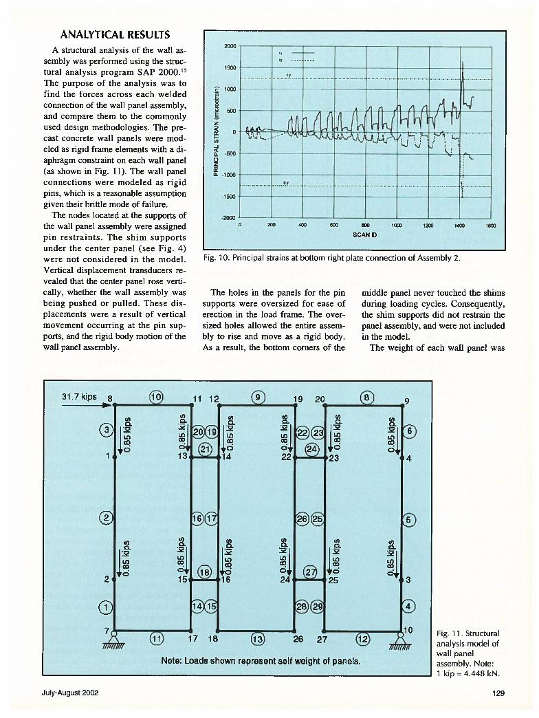
ANALYTICAL RESULTSA structural analysis of the wall as
sembly was performed using the structural analysis program SAP 2000.15The purpose of the analysis was tofind the forces across each weldedconnection of the wall panel assembly,and compare them to the commonlyused design methodologies. The precast concrete wall panels were modeled as rigid frame elements with a diaphragm constraint on each wail panel(as shown in Fig. 11). The wall panelconnections were modeled as rigidpins, which is a reasonable assumptiongiven their brittle mode of failure.
The nodes located at the supports ofthe wall panel assembly were assignedpin restraints. The shim supportsunder the center panel (see Fig. 4)were not considered in the model.Vertical displacement transducers revealed that the center panel rose vertically, whether the wall assembly wasbeing pushed or pulled. These displacements were a result of verticalmovement occurring at the pin supports, and the rigid body motion of thewall panel assembly.
The holes in the panels for the pinsupports were oversized for ease oferection in the load frame. The oversized holes allowed the entire assembly to rise and move as a rigid body.As a result, the bottom corners of the
middle panel never touched the shimsduring loading cycles. Consequently,the shim supports did not restrain thepanel assembly, and were not includedin the model.
The weight of each wall panel was
Fig. 11. Structuralanalysis model ofwall panelassembly. Note:1 kip=4.448kN.
2000
1500
1000
to0
. 500E2
I-.a,
500
to
-1000
cy
-1500
•20000 200 400 600 800 1000 1200 1400 1600
SCAN ID
Fig. 10. Principal strains at bottom right plate connection of Assembly 2.
31.7kips 8 11 12 c)U)
U)0
l. -
‘Lf) IL)
13
U)cI).2-
iazV0
0 U)
2 2110 If)
+0 0
14 22
U) U)a a
2IL)
0
16 24
2D
2
C7
Coa
023
U).2-I.I a25
19 20
23
25
29
26 27
9
4
3
10
(ii) 17 16Il//Iff/Il
Note: Loads shown represent self weight of panels.
July-August 2002 129

31.7 kips
Fig. 12. Resultsof structuralanalysis for
maximum lateralload applied to
the wallassembly.
Note: 1 kip =
4.448 kN.
applied as a point load at four different nodes on each wall panel (see Fig.11). The average maximum force atfailure, 31.7 kips (141.0 kN), was applied as the lateral load at the top leftcorner of the wall panel assembly tofind the capacity of each welded connection. The structural analysis resultsare shown in Fig. 12.
For the above conditions, the shear
Fig. 13. General component behavior of the welded connectors of eight wallassemblies. Note: 1 kip = 4.448 kN; 1 in. = 25.4 mm.
Force-Displacement Relationshipof Welded Connection
The force-displacement relationshipof each welded connection was foundby plotting the relative vertical displacement of two adjoining wall panels versus the shear force across thewelded connection. The relative displacement of two adjoining wall panels in the vertical direction was foundby subtracting data retrieved from displacement transducers DT2 and DT3(see Fig. 4).
The shear force across each connection was found as follows: the forceapplied by the hydraulic actuator onthe wall assembly was multiplied bythe ratio of the average maximumforce at failure of the welded connection, or 16.6 kips (73.8 kN), to the average maximum force at failure of thewall panel assembly, or 31.7 kips(141.0 kN). This assumption is reasonable because the connections behavein a linear elastic manner.
The hysteresis curve for the connectors of eight wall panel assemblies, was approximated by a generalcomponent behavior curve as described in the “Guidelines for the
16.1 kps
Note: A negative sign represents compression.
force at failure of the welded connec- Using this design value, the connectiontions was 15.0 kips (66.7 kN) on the will safely stay in the elastic range.two left connectors, and 16.6 kips(73.8 kN) on the two right connectors.This is significant because the capacityof this connection typically used in design is equal to 8 kips (35.6 kN).Structures built with these welded connections were safely designed with anapproximate factor of safety of 1.9.
U,
w0
0U-
0 0.01 0.02 0.03 0.04 0.05
RELATWE VERTICAL DISPLACEMENT OF CONNECTED EMBEDDED ANGLE (in.)
0.06
130 PCI JOURNAL

Seismic Rehabilitation of Buildings,”FEMA 273.14 Fig. 13 shows the general component behavior curve for theconnectors of eight wall assemblies.The average elastic force on the connectors was 14.7 kips (65.4 kN), andthe average ultimate force was 17.1kips (76.1 kN).
The force-displacement relationshipis linear until the connection fails in abrittle manner. This connection shouldbe designed to remain elastic due to itsbrittle mode of failure and limitedductility.
Analytical Model ofWelded Connection
The probable resisting mechanismsof the connector under considerationare bearing and tension actions in thedeformed anchor bars, as well as bearing of the angle section. Many designers currently model this welded connection with the truss analogy asdescribed in the PCI Design Handbook.16
Fig. 14 is an illustration of the trussanalogy. The following equations areused to describe this model:
whereCU = compression forceTu = tensile force
= capacity reduction factor =0.9
0 = angle of deformed anchorbar 45 degrees
A area of 3/8 in. (9.5 mm) diameter deformed anchor bar= 0.13 sq in. (71 mm2)
f = yield strength of mild steelreinforcement [= 60 ksi (420MPa)j
VRU = vertical shear force resistedby connection
(1) The equations from the truss analogy yield a vertical shear resistance of
(2) 8.4 kips (37.4 kN) for each connection. The analysis indicates that theaverage capacity of this connection isbetween 15.0 and 16.6 kips (66.7 to73.8 kN). The truss analogy is a conservative design methodology whenapplied to this connection.
The following is a list of some ofthe differences between the truss anal-
ogy and the connection under consideration:
a. The angle 0 for this connectionequals zero, not 45 degrees (see Fig.2).
b. The deformed anchor bars arebent 90 degrees into the back of theangle (see Figs. 2 and 3). The bars willnot be able to develop the full tensilecapacity as described in the truss analogy. The deformed anchor bars actmore as /8 in. (9.5 mm) studs with ineffective tails rather than bars in tension.
c. The truss analogy does not account for the bearing of the angle assembly into the concrete. Angle bearing is one of the main force resistingmechanisms of the connection.
Fig. 15. Statics ofdeformed anchorbar at failure forcurrent connection.Note: 1 kip = 4.448kN, 1 in. 25.4mm;1 k-in.= 133N-rn.
T
Anchor bar
This bar is ignoredintheTruss Analogy
V
Angle section
9 = 0° for the connector tested
CL
Fig. 14. Truss analogy model for welded connection.
Cu Tu 1lAfy
VRU = (Cu + Tu )cos0
3/8’ dia. x 12”deformed anchor bar
F= 8.3kips
(ultimate force at failure)
1 112’x114”x2”x6” Angie
M= 10.4k-in.
F = 0 kips compression(bearing is lost againstconcrete at failure)
I F=16.6kips
11/2”(applied force at failure)
July-August 2002 131

Fig. 15 illustrates that the deformedanchor bar cannot fully develop in tension due to the eccentric load from thebend in the bar. Assuming the forcetaken by each vertical deformed anchorbar is 8.3 kips (36.9 kN) (half of thetotal vertical shear force taken by theconnection), the maximum shear andmoment taken by each vertical deformed anchor bar is 8.3 kips and 10.4kip-in. (36.9 kN and 1.17 kN-m), respectively. The eccentric load causesthe deformed anchor bars to quicklytear free from their welds as soon as theconcrete crushes around the connection.
PROPOSED NEW WELDEDCONNECTION
The most effective way to improvethis connection is to provide a largersurface area for concrete bearing andto minimize eccentric loads from thedeformed anchor bars. Fig. 16 is adrawing of a proposed new embeddedangle assembly. The angle is replacedby a 6 in. (152 mm) long ST2x3.85 tocreate a greater bearing area in theconcrete.
One continuous deformed anchorbar replaces the two vertical deformedanchor bars of the previous connection. The vertical deformed anchor baris attached to the back of the embedded angle assembly with a 4 in. (102mm) long, in. (4.8 mm) fillet weld.The vertical deformed anchor bar isbent at 5 degrees to minimize eccentric loads and to ensure adequate concrete cover.
The strength of this fillet weld canbe described by Eq. (3), and thestrength of the base metal can be described by Eq. (4), as:’7
bR = 0.75te(0.6F) (3)
= 0.75t(0.6F) (4)
wherebR = strength of fillet weld or base
materialF = strength of electrode = 70 ksi
(483 MPa)F = tensile strength of base mate
rial =60 ksi (420 MPa)te = 0.707aa = weld size = /16 in. (4.8 mm)t = thickness of base material =
/16 in. (7.9 mm)
Eq. (3) yields the strength of the fillet weld as 4.2 kips per in. (0.74kN/mm), and Eq. (4) yields thestrength of the base material as 8.4kips per in. (1.47 kN/mm). A 4 in.(102 mm) long weld gives a strengthof 16.8 kips (74.7 kN), which is significantly higher than the allowable shearresistance of the welds in the testedconnection. In addition, the concretewill not easily break away from theconnection due to the increased bearing area with the web of the structuraltee embedded into the wall.
DISCUSSION OFTEST RESULTS
Engineers prefer the panel connections, not the panels themselves, to bethe weak link in the system. This investigation has shown that the connections are in fact the weakest link. Although the loose-plate connectionused in this research effectively transferred the applied shear forces, theconnection failed in a brittle manner.
The small displacement ductility exhibited by the welded connections islost as soon as the deformed anchorbars on the back of the embeddedangle fracture from their welds. Fail-
ure occurs before shear yielding cantake place in the welded plate.
These tests reveal that hollow-coreprecast concrete panels can be used inseismic regions provided that the connections can be improved. To this end, anew welded connection is proposed;ductility may be restored to the systemby increasing the surface area for concrete bearing and by reducing the eccenti-ic load in the deformed anchor bars.
If the connection is a location ofductile inelastic deformation, the precast concrete panels will remain elasticunder seismic response. Damage to theoverall structure will be reduced andrepair of the structure will be lesscostly. Ductility in shear wifi allow theforce to redistribute among individualconnectors. Ductility will enable allconnectors to reach their full strength,thereby increasing the overall force resisting capability of the structure.
For existing connections of the typetested in this investigation, a seismicretrofit option has been studied using acarbon fiber composite connection,which will be published shortly.
CONCLUSIONSSimulated seismic load tests of
loose-plate vertical connections be-
ST2x3.85
Fig. 16. Details of proposed new embedded angle assembly. Note: 1 in. = 25.4 mm.
132 PCI JOURNAL

tween precast concrete wall panelswere performed. Based on the resultsof this investigation, the followingconclusions can be drawn:
1. The loose-plate connection commonly used in precast construction canresist relatively high shear forces.
2. The connection fails in a brittlemanner when the deformed anchorbars tear free from the embedded angles, which occurs as soon as the concrete crumbles around the embeddedangle assemblies; as a consequence,the connection possesses little ductilecapacity.
3. The connection should be designed to remain elastic; in its current
form, the connection is not suitable foruse in areas of high seismic regions(Zones 3 and 4).
4. The design methodologies commonly used for this connection areconservative.
5. The connection can be modifiedto increase its ductile behavior by providing more surface area for concretebearing, and by minimizing eccentricloads in the deformed anchor bars.
ACKNOWIEDGMENTThe authors would like to acknowl
edge the funding provided by XXsysTechnologies, Inc., and the Center for
Composites in Construction at theUniversity of Utah.
The authors wish to express theirgratitude to Eagle Precast Company(Monroc, Inc.), for providing the precast wall specimens.
The authors would like to thankVladimir Volnyy and Professor JanosGergely for their assistance with thetests. In addition, the authors aregrateful to Philip Richardson and CarlWright of Eagle Precast Company fortheir suggestions.
Lastly, the authors want to expresstheir appreciation to the PCI JOURNAL reviewers for their thoughtfuland constructive comments.
REFERENCES1. Rostasy, F. S., “Connections in Precast Concrete Structures —
Continuity in Double-T Floor Construction,” PCI JOURNAL,V. 7, No. 4, 1962, pp. 18-48.
2. Scoggin, H. L., and Pfeiffer, D. W., “Cast-in-Place ConcreteResidences with Insulated Walls-Influence of Shear Connectors on Flexural Resistance,” Journal of the PCA Research andDevelopment Laboratories, V. 9, No. 2, 1967, pp. 2-7.
3. Abdul-Wahab, H. M. S., “Ultimate Shear Strength of VerticalJoints in Panel Structures,” AC! Structural Journal, V. 88, No.2, March-April 1991, pp. 204-213.
4. Spencer, R. A., and Neille, D. S., “Cyclic Tests of WeldedHeaded Stud Connections,” PCI JOURNAL, V. 21, No. 3,May-June 1976, pp. 70-81.
5. Stanton, J. F., Hawkins, N. M., and Hicks, T. R., “PRESSSProject 1.3: Connection Classification and Evaluation,” PCIJOURNAL, V. 36, No. 5, September-October 1991, pp. 62-71.
6. Schultz, A., Tadros, M. K., Juo, X. M., and Magana, R. A.,“Seismic Resistance of Vertical Joints in Precast Shear Walls,”Proceedings, XII FIP Congress, Washington, DC., May 29 -
June 2, 1994.7. Low, S.-G., “Behavior of a Six-Story Office Building Under
Moderate Seismicity,” University of Nebraska, Lincoln, NE,May 1995.
8. Priestley, M. J. N., Sritharan, S., Conley, J. R., and Pampanin,S., “Preliminary Results and Conclusions from the PRESSSFive-Story Precast Concrete Test Building,” PCI JOURNAL,V. 44, No. 6, November-December 1999, pp. 42-67.
9. Pincheira, J. A., Oliva, M. G., and Kusumo-Rahardjo, F. I.,“Tests on Double-Tee Flange Connectors Subjected to Mono-tonic and Cyclic Loading,” Research Report, University of
Wisconsin, Madison, WI, 1998.10. Strigel, R. M., Pincheira, J. A., and Oliva, M. G., “Reliability
of 3/8 in. Stud-Welded Deformed Bar Anchors Subject to Tensile Loads,” PCI JOURNAL, V. 45, No. 6, November-December 2000, pp. 72-82.
11. Lemieux, K., Sexsmith, R., and Weiler, G., “Behavior of Embedded Steel Connectors in Concrete Tilt-Up Panels,” AC!Structural Journal, V. 95, No. 4, July-August 1998, pp. 400-413.
12. Pantelides, C. P., Reaveley, L. D., Gergely, I., Hofheins, C.,and Volnyy, V., “Testing of Precast Wall Connections,” University of Utah, Department of Civil and Environmental Engineering, Report UUCVEEN 97-02, 97-03, 98-01, Salt LakeCity, UT, 1997-98.
13. Hofheins, C., “Welded Loose-Plate Connections for Hollow-Core Precast Wall Panels,” M.Sc. Thesis, Department of Civil& Environmental Engineering, University of Utah, Salt LakeCity, UT, May 1999.
14. Building Seismic Safety Council, “NEHRP Guidelines for theSeismic Rehabilitation of Buildings,” FEMA Publication 273,Federal Emergency Management Agency, Washington, DC,October 1997.
15. SAP2000 Analysis Reference, Computers and Structures, Inc.,V. I, Berkeley, CA, 1997.
16. PCI Committee on Industry Handbook, PCI Design Handbook: Precast and Prestressed Concrete, Fifth Edition, Precast/Prestressed Concrete Institute, Chicago, IL, 1999.
17. Salmon, C. G., and Johnson, J. E., Steel Structures Design andBehavior, Fourth Edition, Harper Collins College PublishersInc., New York, NY, 1996.
APPENDIX A — NOTATIONAb = area of reinforcing bar
A = area of deformed anchor barC = compression forceFey = strength of electrode
f = steel stress
F1 = tensile strength of base material
f = yield stress of reinforcementn = number of reinforcing bars
QcE = expected strength
QCL = lower-bound strengthR = strength of fillet weld or base materialt = thickness of base material
= effective area of weld
T = tensile force
VRU = vertical shear force resisted by connectionV5 = shear strength of connection0 = angle of deformed anchor bar
= capacity reduction factor
July-August 2002 133