Embed Size (px)
Citation preview

Journal of Traffic and Transportation ~ngineeringCEnglish Edition)
2014,1(1) :62-71
Behavior of composite rigid frame bridge underbi-directional seismic excitations
Xiaogang Liu, Jiansheng Fan *, Jianguo Nie, Guo Li
Department of Civil Engineering, Tsinghua University, Beijing, China
Abstract: Pushover analysis and time history analysis are conducted to explore the bi-directional
seismic behavior of composite steel-concrete rigid frame bridge, which is composed of RC piers
and steel-concrete composite girders. Both longitudinal and transverse directions excitations are
investigated using OpenSees. Firstly, the applicability of pushover analysis based on the funda
mental mode is discussed. Secondly, an improved pushover analysis method considering the
contribution of higher modes is proposed, and the applicability on composite rigid frame bridg
es under bi-directional earthquake is verified. Based on this method, an approach to predict the
displacement responses of composite rigid frame bridge under random bi-directional seismic ex
citations by revising the elasto-plastic demand curve is also proposed. It is observed that the de
veloped method yield a good estimate on the responses of composite rigid frame bridges under
bi-directional seismic excitations.
Key words: composite rigid frame bridge; bi-directional seismic excitation; pushover analysis;
time history analysis
1 Introduction
Continuous rigid frame bridge has a rigid connec
tion between the girders and piers, making them
work together under lateral loads. Meanwhile,
the piers are subjected to both axial force and
flexural moment, especially, generate negative
flexural moment in the end of girders. For this
benefit, the positive flexural moment at mid-span
will decrease. This will reduce the cross-sectional
• Corresponding author: Jiansheng Fan, PhD, Professor.E-mail: [email protected].
height of girders correspondingly. Composite rig
id frame bridge comprises of steel-concrete girder
and RC piers or composite piers. The advantages
of such structural solution include better seismic
performance and convenience in constructionCNie
2011). Rigid frame bridges are widely used in
highway overpasses, viaducts and railway bridg
es, especially in Chinese western areas. As these
bridges are usually used in the areas with great re
quirement for seismic resistance, their seismic
?1994-2014 China Academic Journal Electronic Publishing House. All rights reserved. http://www.cnki.net
(1)
Journal of Traffic and Transportation EngineeringCEnglish Edition)
performances need further research.
Although the direction of seismic excitation is
randomly varied. most of investigations only fo
cused on uni-directional responses along bridge
longi tudinal or transverse direction. Previous
studies have confirmed that bi-directional seismic
excitations have significant influence on structure
responses. especially when the bridge structures
are under elasto-plastic stage CDe Stefano et al.
1998; Heredia-Zavoni and Machicao-Borrniuevo
2004). Furthermore. the influence of bi-direction
seismic excitations is also relative to seismic inten
sity and bridge structural features CLopez and
Torres 2000; Wang et al. 2004). The responses of
bridge structures are dependent on the variation
of seismic excitation input direction. Usually, the
most unfavorable input direction does not coin
cide with the bridge longitudinal or transverse di
rectionC Li et al. 2010; Lopez and Torres 1997;
Wilson et al. 1995). Therefore. it is necessary to
conduct further analysis on the seismic behavior
of composite rigid frame bridge under bi-direc
tional seismic excitations.
Some methods can be used for bridge seismic
behavior analysis. Time history analysis has the
best accuracy, but the computational cost is also
the greatest. Relatively. pushover analysis has
lower computational cost as well as acceptable ac
curacyCYang et al. 2000). Pushover analysis was
first proposed in 1970s. With great previous re
search in past years. it has become a good instru
ment for seismic analysis. Saiidi and Sozen(1981)
proposed an approach to replace the multi degree
of freedom system (MDOF) by single degree of
freedom system CSDOF). Fajfar and Gaspersic
(1996) improved the application of capacity spec
trum in pushover analysis. On these bases. Gupta
and Kunnath (2000) proposed a better applicable
pushover analysis approach. To account for the
influence of higher modes. Chopra and Goel
( 1999) proposed model combination pushover
analysis approach. Vidic et al. (1994) and Cho
pra and Goel ( 1')9') also improved the capacity
spectrum to account for the elasto-plastic behav
ior. making pushover analysis applicable in elas-
63
to-plastic seismiC response. Besides. Krawinkler
and Seneviratna ( 1998 ). Mwafy and Elnashai
(2001) and Yang et al. (2000) also conducted
much work on pushover analysis. including load
patterns. determination of target displacement.
accuracy evaluation and applicable conditions.
Pushover analysis was originally used in seismic
analysis for building structures. After Northridge
and Kobe earthquakes. this approach was also de
veloped in seismic analysis for bridge structures.
Paraskeva et al. C2(04) first evaluated the appli
cability of modal pushover analysis in seismic be
havior evaluation for bridges. and Lu et al.
C2004) evaluated the applicability of pushover
analysis in steel arch bridges. In China. pushover
analysis was also used in seismic behavior evalua
tion of bridge piers( Qian et al. 2006; Wang et al.
2000; Qin 20(8). However. little research re
garding pushover analysis of composite rigid
frame bridge can be referred to. Furthermore.
the influence of higher modes and bi-directional
seismic excitations on the seismic behavior of
composite rigid frame bridge is also unclear. In
this study. pushover analysis in both longitudinal
and transverse directions on composite rigid frame
bridge will be conducted. and a new seismic re
sponses prediction approach under bi-directional
seismic excitations will be proposed using push
over analysis.
2 Pushover analysis method
Based on site condition and structure damping ra
tio. the corresponding elastic response spectrum
for specific seismic wave can be obtained. The
S.e-Sde demand curve can be derived by Eq. (1 )
using elastic response spectrum.
{
Sae=filxolmax
T1
Sde = 4--,Sac1(-
Applying specific load pattern on structures. an
overall load-displacement curve can be obtained
when conducting pushover analysis using FEA
method. The Sa-Sd capacity curve can be obtained
by Eq. (2) using load-displacement curve.
?1994-2014 China Academic Journal Electronic Publishing House. All rights reserved. http://www.cnki.net
64 Xiaogang Liu et al.
established using OpenSees (Open System for
Earthquake Engineering Simulation) to conduct
elasto-plastic time history analysis and pushover
analysis( Mazzoni et al. 2(06). Piers and girders
were all defined as nonlinear beam element based
on cross-sectional fibers. This nonlinear beam el
ement has 5 integration points along axial direc
tion with good accuracy and computational effi
ciency. Mass of piers, girders and vehicle loads
were simplified as lumped mass. Rayleigh damp
ing was used in FE analysis and material damping
ratio was 5%.
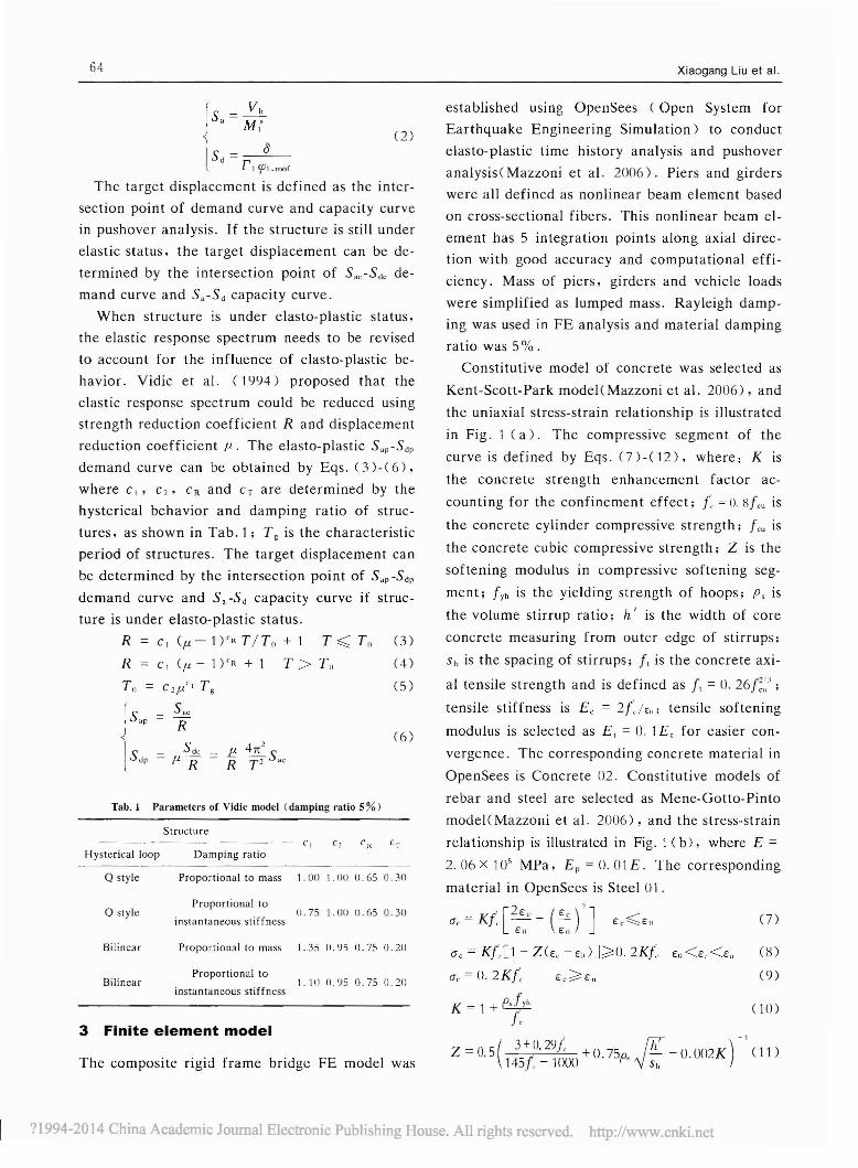
Constitutive model of concrete was selected as
Kent-Scott-Park modelCMazzoni et al. 20(6), and
the uniaxial stress-strain relationship is illustrated
in Fig. 1 (a). The compressive segment of the
curve is defined by Eqs. (7)-(12), where: K is
the concrete strength enhancement factor ac
counting for the confinement effect; t: =O. Hfeu is
the concrete cylinder compressive strength; feu is
the concrete cubic compressive strength; Z is the
softening modulus in compressive softening seg
ment; fYh is the yielding strength of hoops; Ps is
the volume stirrup ratio; h I is the width of core
concrete measuring from outer edge of stirrups;
Sh is the spacing of stirrups; f, is the concrete axi
al tensile strength and is defined as ft = O. 26f~~J;
tensile stiffness is E e = 2{1E,,; tensile softening
modulus is selected as E, = O. 1E e for easier con
vergence. The corresponding concrete material in
OpenSees is Concrete D2. Constitutive models of
rebar and steel are selected as Mene-Gotto-Pinto
model(Mazzoni et al. 20(6), and the stress-strain
relationship is illustrated in Fig. 1 (b), where E =
2.06 X 10⁵ MPa, E p = O. 01 E. The corresponding
material in OpenSees is Steel 01.
(2)
(6)
C Rc,Damping ratio
Proportional to mass 1.00 1.00 0.65 O..,0
Structure
JS.P = SRe
1SdP = f1 S~e = f :;: S.e
Tall. 1 J>'lrameters of Vidic model (damping ratio 5 %)
Q style
Hysterical loop
15• = ;~
5 - 0d - r t CPt.,oof
The target displacement is defined as the inter
section point of demand curve and capacity curve
in pushover analysis. If the structure is still under
elastic status, the target displacement can be de
termined by the intersection point of S.e-Sde de
mand curve and S,-Sd capacity curve.
When structure is under elasto-plastic status,
the elastic response spectrum needs to be revised
to account for the influence of elasto-plastic be
havior. Vidic et al. (1994) proposed that the
elastic response spectrum could be reduced using
strength reduction coefficient R and displacement
reduction coefficient f1. The elasto-plastic S"P-Sdp
demand curve can be obtained by Eqs. (3)-(6),
where c\' C" CR and Cr are determined by the
hysterical behavior and damping ratio of struc
tures, as shown in Tab. 1; T g is the characteristic
period of structures. The target displacement can
be determined by the intersection point of S"p -SdP
demand curve and S. -Sd capacity curve if struc
ture is under elasto-plastic status.
R=c\(/l-l)'RT/Tn +l T~Tn 0)
R = C\ (/l - 1 )'R + 1 T> T" (4)
Tn = C'/l'T T g (5)
Q styleProportional to
instantaneous stiffness0.75 1.000.650.30
(J, = Kr[2€e - (~)'J€o €o
(7)
3 Finite element model
The composite rigid frame bridge FE model was
( 10)
(9)
(Je = Kf[l - Z(€, -€n)]~O. 2K!, €"<€"<€u
(Je = D. 2Kf~ €e~€u
K = 1 + PsfYhf.
Z = O. 5( 3 +0. 29f + 0 75. W - 0 O()? K ) - \ (10145f, - 1000 . p, '\j s;: .-
1.35 0.95 0.75 0.20
1. 1() 0.95 0.75 0.20
Proportional to mass
Proportional to
instantaneous stiffnessBilinear
Bilinear
?1994-2014 China Academic Journal Electronic Publishing House. All rights reserved. http://www.cnki.net
..IoJrnal ot Traffic and Transportation EngineeringCEllglish Edition) 65
E
o •
"""_-0.JS7g
20 30 40
n·)(b) EICUlro
"
0,2
,.,:;; , IIi'I'i~v"•
-0.1,,_-o.179.r
-0.2," " 30 " "n.)
(.) T.ft...0.2
:;; ,•
-0.2
( 12)(', =O.U02K
= O. 00" + 0. 9p./•• ]l)()
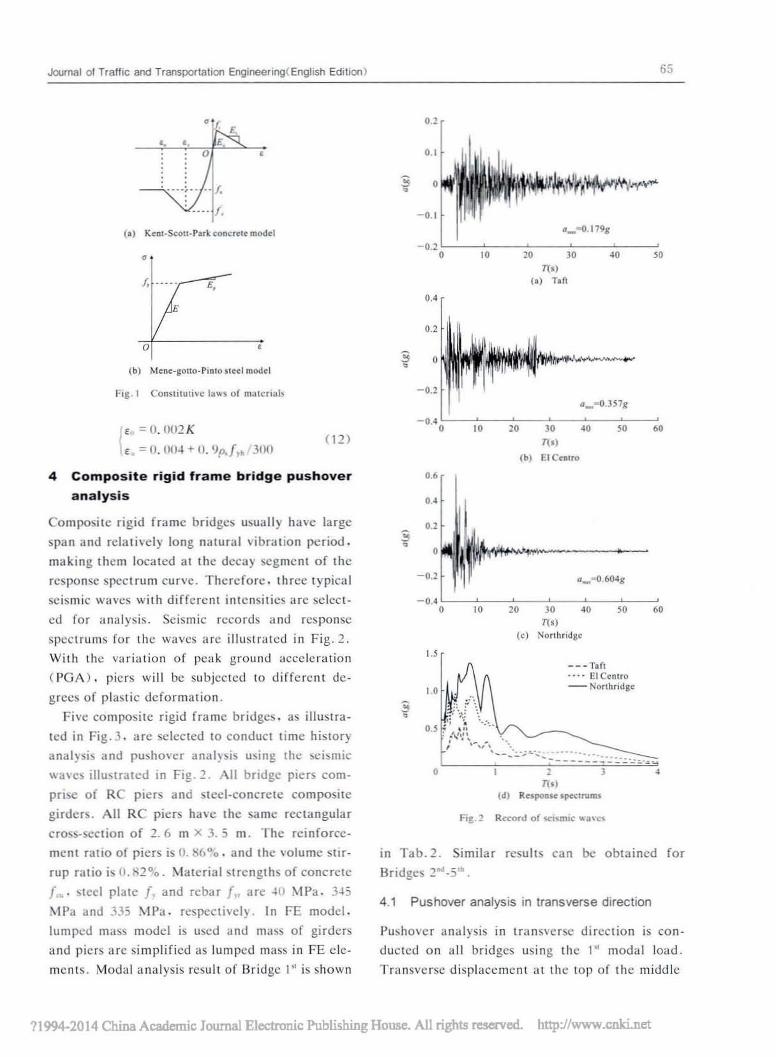
Fig. I Conslllluhc laws of n!;llcri:t1,
•
•
.... I.
f, .... E.
"". E
(b) Mene-lIo11o,P,nlo $leel model
_.. -,_ ... f.
Fi&.2 Ro:ord of ~Ism".· ""a\CS
4.1 Pushover analysis in transverse direction
""
---Tin.•.. III Centro- Norlhridlle
20 30 40n·)
(e) Norlhndgc
,:' '1.j ':O.j ." .,', ";'..
,N':~_ ~, '" . ..,-~':"'';'''': ..... '.
~ -- - - _..: ::::.: ::..: '-= :....,'----,---t,===~,=""'~.n.)
(d) Response lpeclmms
'.6
",.,:;;• ,
-0.2
-0.4,
I'
..,
Pushover all<lIysis in tTllllSVCrSC direction is can
dueted on all bridges using the I" modal load.
Transverse displacement at the lOp of the middle
in Tab.2. Similar results call be obtained for
Bridges 2001 .5" .
4 Composite rigid frame bridge pushover
analysis
Composite rigid frame bridges usually have large
span and relatively long natural vibration period.
making them located at the decay segment of the
response spectrum curve. Therefore. three typical
seismic waves with different intensities lire select
ed for an<llysis. Seismic records and response
spectrums for the waves arc illustrated in Fig.2.
With the variation of peak ground acceleration
(PGA). piers will be subjected to different de
grees of plastic deformation.
Five composite rigid frame bridges. as illustra
ted in Fig.3. are selected to conduct time history
anal)si~ and pusho\'cr anal)si~ u~ing the ~i~mic
\\a\cs illustrated in Fig.2. All bridge piers com
prise of RC piers and steel-concrele composile
girder~. All RC piers ha\c the same rectangular
cross-section of 2.6 m x 3.5 m. The reinforce·
ment rallO of piers is (J. H6°o. and the \olume sllr
rup ratio is O.H2°o . Material slTcngths of concrete
/ .... steel plate /. and rebar {.. arc ~ll MPa. 3~5
MP,I and JJ5 MPa. rcspccti\cl}. In FE model.
lumped milSS model is used and mass of girders
and picrs arc simplified as lumped m,ISS in FE ele
ments. Modal analysis result of Bridge 1" is shown
71994-2014 China Academic Journal Electronic Publishing House. All rights reserved. http://www.cnki.net

66
" " ,
If] I I(.) Bridlf ,"
" " "
Xiaogang Liu el al
mic wave can be obtained by procedures detailed
in Section 2. Pusho\'er analysis and time history
analysis are conducted using each seismic wave.
and the comparison of target displacements by
pushover analysis and the maximum displaccmcni
by lime history analysis are shown in Tab.3.
·hb.) Mesult tomparl_ or pllliho.ft" analysis and II..,., hlstor,
analysis in bridJ:" tno'I!i"~ dindi9n
Fig.] ijridge mo<Jcls(Unit, m)
o•
" '1'
(b) Dridll~ 2"
" "
I
Middle pier topBridge Seismic displacement( 10m) Dc"iation( <v.)No. wa,·c
l'ushover Time histroy
Taft 20J \(,0 "IJridgcEl Cemro '" J55 "'" Nonhridgc ,.. .., 25
Taft 30' 2201 J5
,. E1 Cenlro -lS'} ", "Northridge 823 '" 25
Tafl 26J '" J5
J. E1 (;(cntro ." J77 JJ
Nonhridgc "0 .., 16
Taf! 101 ,W ," El Centro 272 2111 J
Northridge -150 "0 ,Taft 212 '" J2,. El Centro m '" 29
Northridge '"' '" "Tab. '1 Vihrati"" l)('riuoJ~ "nd "willes
Mode No. Vibration pcriod(sl Vibration mode
4.2Sfl.g Transverse
, 2.1!175 Transverse
J I.H7J Trans'·crsc
, 1.7JJJ Longitudinal
5 0.%75 Tr~nsn"sc
• O.72'}2 Trlns\'crsc
, O.70H Trallli'"enc
, 0.558l Longitudinal
9 0.45UO Longitudinal
'" O.41{>.l Longitudinal
pier and transverse bottom shear force of the mid
dle pier are selected as the [oad-displacement
curve. The larget displllCClTlCnl for specific seis-
If piers are not quite high. the target displace
ment by pushover analysis using the ,. modal load
will fit well with the maximum displacement by
time history analysis. The deviations of pushover
anal)'sis and time history analysis for Bridge -I'~ do
not exceed 10010 for all seismic waves. Besides.
the increase of span number will have linle influ
ence on the deviations if lhe maximum span is un
changed. However. Wilh the increase of pier
height and maximum span. the analysis resull by
pushover analysis becomes significantly gre,lter
than that by time history analysis. The devialions
of Bridges 1". 2.... 31<1 and 5'~ ,Ill exceeds 20% for
all seismic waves. which indicates thai the influ
ence of higher modes of vibration cannOI be ncg
lected.
11994-2014 China Academic Journal Electronic Publi5hing House. All rights roscrvcd. http://www.coki.nct

Journal of Traffic and Transportation EngineeringCEnglish Edition) 67
To account for the influence of higher vibration
modes, an adaptive pushover analysis method was
proposed( Gupta et al. 20(0) and a modal push
over analysis method was also proposed (Chopra
et al. 2(02). The procedures of the former meth
od are very complex, making it difficult to be ap
plied. The latter method usually overestimates
structural response. Therefore, a new pushover
method similar with modal pushover analysis
method is proposed. The influences of the target
displacements for major vibration modals are con
sidered, and the final target displacement is ob
tained by the combination of target displacements
for major vibration modals according to the con
tribution of each modal (equivalent mass coeffi
cient). The calculation procedure is detailed in
Eqs. (13)-(15).
Tab. 4 Result comparison of pushover analysis considering
contribution of higher vibration modals and time history
analysis in bridge transverse direction
Obviously, the result of this new pushover meth
od accounting for the influence of higher vibra
tion modals fits well with that of time history
analysis.
Middle pier top
displacement( mm) Deviation
(%)
Pushover Timehistroy
175 160 9.0
390 355 10.0
654 607 8.0
251 224 12.0
38<) 384 1.0
6'>7 65') 6.0
226 1')5 16.D
423 377 12.D
771 665 16.0
118 110 7.0
312 281 11.0
485 440 10.0
183 161 14.0
375 368 0.2
688 643 7.0
wave
Taft
SeismicBridge
No.
El Centro
Northridge
El Centro
Taft
Taft
lSI El Centro
Northridge
Northridge
yd El Centro
Northridge
Northridge
2nd El Centro
Taft
Taft
( 14)
(15)
( 13)N
2..: m i!P]ij= 1
N
(2..:mj!pji)2j=1
; = 1
Mt-N--
2..: mi
d = ..:..i-_-1,--_II
~rii = 1
where Mt is the modal mass for the i lb vibration
modal; m; is the lumped mass; !pj; is the standard
vibration model coefficient; r; is the contribution
coefficient for the i Ib vibration modal (equivalent
mass coefficient); d; is the target displacement
by pushover analysis for major vibration modal;
d is the final target displacement by pushover
analysis method.
It should be noted that the contribution coeffi
cient of transverse vibrations should be zero for
longitudinal vibration, and the contribution coef
ficient of longitudinal vibrations should be zero
for transverse vibration.
New pushover analysis by the proposed method
using the transverse vibration modals in the first
10 vibra tion modals is conducted for each bridge.
The final target displacements for all bridges by
this new pushover method are shown in Tab.4.
4.2 Pushover analysis in longitudinal direction
Pushover analysis in longitudinal direction is con
ducted on all bridges using the 151 modal load. As pier
top displacements along longitudinal direction are al
most the same for all piers in one bridge, longitudinal
displacement at the top of middle pier and the sum of
longitudinal bottom shear force of all the piers are se
lected as the load-displacement for capacity curve.
The target displacement for specific seismic wave
can be the obtained by procedures detailed in Sec
tion 2. Pushover analysis and time history analysis
are conducted using each seismic wave, and the
comparison of target displacement by pushover
analysis and the maximum displacement by time
history analysis are illustrated in Fig. 4. As can be
seen, the target displacement of the pushover
?1994-2014 China Academic Journal Electronic Publishing House. All rights reserved. http://www.cnki.net

68 Xiaogaog Uti el at
Norlhridge
NClrlhridgcEl CentroSeismiewue
(e) Bridge)"
£1 CentroSd,micwlvc
(M) Il'idgc I"
£1 Cntn!~;,mlcwlvc
(b) Brid,e 2"
ToO
Tlfi
EI CnitO!kismie ..·.ve
(d) Brodie'·
T.n
(5;SS!Pushovcr_ Time: hiltory
~Pusbo"cr
_Time ~'5tOry
&SSJ Pusbovcr..Timc ~1510ry
em Pushoverm:ra Time ~i510ry
•
'00
•
-.~c )00
•~ 200•'"r. 100
•
fiB.:; Comparison of pu~ho,cr lInal)'Sl$ conSidering contribuuon
or h'Bhcr vibn'lllon modals lind liD><' h,story analysis in
bridge lon&l1udc dm~cllon
5 Pushover analysis under bi-directional
seismic excitations
There is significant difference between seismic
Fig. 5. Obviously. the result of this new pushover
method considering the influence of higher vibra
lion modals fits better wilh that of time history
analysis.
.,.-.f ),. _ r".hovc.
• _ Time hillory, ,,.•~•~
'00
• •
...-. _Pusbov~.
i _Timehislory
• ...,i.;; ,,.
f •(.)...-. IilliilI Pushover
~ tim Time hinory,• .,.,•.!0
c6 ".~• •
(b)...-. I'lI::3 r ...boo"c,~ _ Ti_ hillOry,•...•,•.;; ,,.••• •
analysis is obviously lower Ihan the lime history
analysis result. ovcreslimating Siructural seismic
perrorm,tOce.
Similar 10 pushover analysis accounting for Ihe
influence of higher vibration modals. pushover
analysis using the proposed method in Section -I. I
is conducted. The longilUdinal vibration rnodals
in the firsl 10 vibration madals arc conducted for
bridges. The final target displacement considering
high vibration influence modal is illustrated in
Fig. 4 Comparison of pushO"cr anal)"sjSllnd time hislor}'
analysis in bridge lon&"IlGe di.oxlion
11994-2014 China Academic Journal Electronic Publi5hing House. All rights reserved. http://www.cnki.nct
(16)
(17)
(18)
Journal of Traffic and Transportation Engineering( English Edition)
performances of longitudinal direction and trans
verse direction. Thus, bridge structural response
may vary with the input direction of seismic exci
tations. As input direction of actual seismic waves
is random, the influence of bi-directional seismic
excitations may be significant (De Stefano et al.
1998; Heredia-Zavoni and Machicao-Borrniuevo
2004). Previous research has confirmed that the
maximum seismic response of bridges may not oc
cur when seismic input in the longitudinal or
transverse direction alone and the maximum seis
mic responses may be 30% larger when seismic in
put direction is random. The results of SRSS com
bination, EuroCode-8 and Code for seismic design
of buildings may be un-conservative (Li et al.
2011) .
The influence of bi-directional seismic excita
tions on the reduction coefficient of elasto-plastic
response spectrum has the statistical laws for vari
ous vibration periods, structural displacement
ductility coefficients and damping ratios. There
fore, the demand curve can be revised to account
for bi-directional seismic excitations, and SRSS
combination of the final longitudinal and trans
verse target displacements can be selected as the
prediction of the maximum displacement re
sponse. The Sapb-Sdpb demand curve considering
bi-directional seismic excitations can be derived
from Vidic model in Section 2, revising strength
reduction coefficient R and displacement ductility
reduction coefficient p., as shown in Eqs. (16)(19) .
R b =1.4[cl (p.-1)CR T/Tll +1] T~Tll
R b =1.4[c, (p.-1)c R +1] T>T"
i5ae
Sapb =If(19)
_ Sde _ l!:... 41C2
SdPb - p. If - R T2 5 ae
Pushover analysis is conducted on composite
rigid frame bridges in Tab. 5 following the procedures
detailed in Section 2. All parameters of piers and
composite girders are same as detailed in Section 3.
The Sapb-Sdpb demand curve considering bi-directional
seismic excitations is adopted and seismic waves in
Tab. 6 are used for analysis. Pushover analysis
69
considering high vibration modal is conducted for
all bridges in Tab.5 using the first 10 vibration
modes following the procedures detailed in Sec
tions 4. 1 and 4. 2, and the final target displace
ments E xl and E yl for longitudinal and transverse
direction respectively can be obtained. The target
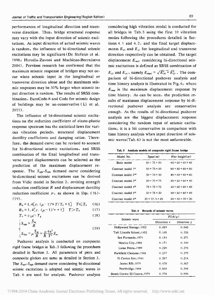
displacement E maxl considering bi-directional seis
mic excitations is defined as SRSS combination of
E x, and Ey! , namely Emax1 = I E~, + E;1 . The com
parison of bi-directional pushover analysis and
time history analysis is illustrated in Fig. 6, where
E max is the maximum displacement response by
time history. As can be seen, the prediction re
sults of maximum displacement response by bi-di
rectional pushover analysis are conservative
enough. As the results of bi-directional pushover
analysis are the biggest displacement response
considering the random input of seismic excita
tions, it is a bit conservative in comparison with
time history analysis when input direction of seis
mic waves<Tab. 6) is not the most unfavorable.
Tab.S Analysis models of composite rigid frame bridge
Model No. Span(m) Pier height(m)
Basic model 50 + 75 + 50 40 + 60 + 60 + 40
Contrast model 1" 50 + 75 + 50 60 + 60 + 60 + 611
Contrast model 2nd 50 + 75 + 50 40 + 611 + 611 + 611
Contrast model yd 50 + 75 + 75 40 + 60 + 60 + 411
Contrast model 4th 75 + 75 + 75 40 + 60 + 611 + 411
Contrast model 5th 50 + 75 + 50 40 + 60 + 60 + 40
Contrast model 6th 25 + 37.5 + 25 20 + 30 + 311 + 20
Tab. 6 Records of seismic waves
PGA(gJSeismic wave
Direction x Direction y
Hollywood Storage. 1952 0.059 0.042
Taft Lincoln School. 1952 0.105 0.156
San Fernando. 1971 0.134 0.271
Mexico City.1985 0.171 o.1110
Lorna Prieta. 1989 0.220 0.276
Parkfield Cholame. 1966 D.237 0.275
El Centro Site. 1'140 0.357 0.214
James RD.1979 0.478 0.367
Northridge. 1'194 0.604 0.344
Bonds Corner El Centro. 197,} 0.778 0.5'15
?1994-2014 China Academic Journal Electronic Publishing House. All rights reserved. http://www.cnki.net

70
• Buio;:model _Coot'ltllDodtl.-.Conlr.1Imodell- ~ Conlrut model S·,., "ConuUI model 2" +ContNlIl model 6-",eOIlUlSl model)"
•• • •0., • • t •
• • • •~
• • • • II • •• • • •0., • t 1 •J • • •• • ••• •... • • •• • •••
" " • ~ • u " 0= ~ ,,; , -' • u " "" • z
!k'JlDle ....,·es
MS.6 ComparISOn of pusho\er anal)sis and l,rot history
anal)"§Is under bi-dm:cllonal Kism".. UClIations
6 Conclusions
Pushover analysis and time history analysis arc
conducted for composite rigid frame bridge using
OpcnSecs. 'ew pushover analysis method consid
ering the influence of higher vibration modal b
proposed. and its applicability lind accuracy in
longitudinal and transverse direction arc evalua
ted. On this basis. the revision of the claslO-plas
tic demand curve is proposed considering bi-direc
tional seismic excitations. A bi-directional push
over analysis prediction approach for target dis
placement response is also proposed. which is
suiwblc for seismic excitations in random input
directions. Conclusions arc drawn as follows:
(I )The influence of high vibration modals
should be considered for composite rigid framc
bridge with high piers and large sp'lns. The new
pushover amllysis method by the combination of
targct disp!;lcements of major modals according to
equivalent mass coefficiclH can predict the dis
placement response of rigid frame bridge in longi
tudinal and transverse direction.
(2)The elasto-plastic demand curc should be rc
\'iscd to account for the influencc of bi-directional
seismic excitations. The target displacements E J ,
and Ey1 for longitudinal and transverse direction
respcctively can be obtained using the revised Sorb
Sdfil> demand curve. and the maximum target dis
placement response considering bi-directional
seismic excitations can be obtained by SRSS com-
Xlaogang liu el at
bination of E J , and E... This bi-directional push
over analysis method considering the random in
put of seismic excitations gives the acceptable pre
diction of target displacement response.
Acknowledgments
The authors gr,lIefully appreciate the financial sup
{X)rt provided by the National Science and Technolo
gy Sup{X)rt Program (No. 2011BAJOlJB(2) and the
National Nlltural Scicncc Foundation of China
(No.5113S007.51222810).
Rertrtnees
Chopn. A. K.. Gocl. R. K.. I'm. Capaelly demand diagram
mel hods ror eSlimaling seismic ddormalion of inelastic strue_
lures SDF Sy~lCm. R~port No. l'EER.19')'). 02. I'aeific Canh.
quake Engineering RCSCitrch Cen(er. Univcrsily of California.
HcrkclC$.
ChOrlll. A. K.. God. R. K.. 2002. A modal pusho,'cr anal)s.s
procrourc ror atimaling sci,mic demands for btllldmJS
~nhqu.a.ke Engmccrlng al'ld 5uucluTllJ D)"I'IamiC'S. 31 (3),
S61·S1l2.
IX Stdaoo. M.. Faella. G.. Ramasco. R.. t'-"JIl. Inclaslic scis·
mlc response of one_way plan·uymmclrie under bi·dimen~ion·
al ground malions. Earthqu:.kc Engineering anll SlruclUral
I»namic. 27(4),363·376.
Fajf,.. I'.. GnperSle_ P.. I'J'H>. N2 mC!hod ror the SClSmlC dam
age anal)'IJ$ or RC b.llld,np. Eanhqu.a.ke EnSlnccnng and
SITUClural Dynamics. 2:;(1), .1146.
Gupla. B.. Kunnalh. 5. K.• 2111111. Adaptile spectra·basal push·
o"cr procedure ror seismiC naluallon or Slruetures. Earth.
quake Spcclra. 1M2), 3(,7·3')1.
Ilcredia-ZIlvoni. E.. /<.lachic;.o-llorrniuevo. C•• 2(~14. Response
10 onhogonal componenlS of ground mOIlOn and assc~smenl of
pcreenlage combil13l1on rules. E<!nhqu.a.ke Enginttring and
51",Clural D)namlC'!. J3L2l, HI·2M.
Kr...·mk1cr. II.. Scnevlratna. G D. P. K .1"9"1. Pros al'ld cons
Or a puslm"er analysis or seismic performance C,... Iu.a.lion. En·
g.ne<:ring SUUClurcs. 2U( -I_t.l, -152....6-1.
Li. GIIO. Fan. Jlansheng. L,. Quanwiong. 21'11. Scism,e response
analysis of eoml)()Sile rigid frame brillge unllcr bi·dlreClional
e~eilalions. Journal of Harbtn InSlilUle of l'cehnology. 43
(52), 32~-USl.
L,. Quan",-ang. hn. Jiansheng. I\IC. Jianguo. 21110. Efrcci of di·
J<.'C"lioa.al unccnalnlY of eanhquake &round mali<><! on SiNe·
tural responses. Enginccnng Mechames. 27{ Ill, 135_1 -II).
Lopez. O. A.. Chopra. A. K.. Ilcrnanllez. J. J.. 2{)OIl. Crnical
rcsponst' of SlruC!urcs 10 mlllli_eomponenl eanhquake cxcila·
lion. Ennhqunkc Engineering anll SlruC1Ur;.! Oynamin. 29
(11),175')·1778.
Lopez. O. A.. lanes. R.. 1'J'J7, The critical angle or >ci>mic in.
eldence and lhe max.mum suuclural response. Earthquake
11994-2014 China Academic Journal Electronic Publishing Hoose. Ali rights reserved. bttp:Ilwww.coki.net

Journal of Traffic and Transportation Engineering(English Edition)
Engineering and Structural Dynamics, 26, 881-894.
Lu, Z. H .• Usami. T .• Ge. H. B., 2004. Seismic performance
evaluation of steel arch bridges against major earthquakes.
Part2: simplified verification procedure. Earthquake Engi
neering and Structural Dynamics. 33(14): 1355-1372.
Mazzoni. S. Mckenna. F. • Scott. M. H .• et al. • 2006. The open
sees command language manual. University of California.
Berkeles.
Mwafy. A. M. Elnashai. A. S.• 2001. Static pushover versus dy
namic collapse analysis of RC buildings. Engineering Struc
tures. 23, 407-424.
Nie. Jianguo. 2011. Steel-concrete composite bridge. People's
Transportation Press. Beijing.
Paraskeva. T. S.• Kappos. A. J .• Sextos. A. G .• 2006. Exten
sion of modal pushover analysis to seismic assessment of bridg
es. Earthquake Engineering and Struetural Dynamies. 35
(10), 1269-1293.
Qian. Jiaru. Kang. Zhao. Zhao. Zuozhou. et al.. 2006. Dis
placement-based seismic safety assessment of existing munici
pal bridges. Engineering Mechanics. 23(SD: 194-202.
Qin. Sifeng. 2008. Static nonlinear analysis methods for estimating
71
seismic performance for bridges. Dalian University of Tech
nology. Dalian.
Saiidi. M.• Sozen. M. A.• 1981. Simple nolinear seismic analysis
of RC structures. Journal of the Structural Division-ASCE.
107(5): 937-952.
Vidic. T .• Fajfar. P.• Fischinger. M.• 1994. Consistent inelastic
design spectra: strength and displacement. Earthquake Engi
neering and Structural Dynamics. 23(5): 507-521.
Wang. Dongsheng. Li. Hongnan. Wang. Guoxin. 2004. Pseudo
constant ductility inelastic spectra for bi-directional ground
motions. Earthquake Engineering and Enghineering Vibra
tion. 24(4): 25-31.
Wang. Dongsheng. Di. Tong. Guo. Mingzhu. 2000. Estimated
seismic vulnerability of bredges by push-over method. World
Information on Earthquake Engineering. 16(2): 47-519.
Wilson. E. L.. Suharwardy. A.• Habibullah. A .• 1995. Aclari
fication of the orthogonal effects in a tree-dimensional seismic
analysis. Earthquake Spectra. 11 (4): 659-666.
Yang. Pu. Li. Yingming. Wang. Yayong. 2000. Improved meth
od of structure pushover analysis. Journal of Building Struc
tures, 2l( 1) , 44-51.
?1994-2014 China Academic Journal Electronic Publishing House. All rights reserved. http://www.cnki.net