Embed Size (px)
Citation preview

BeerTech AirFlow SystemInstallation & Operating ManualC O N T E N T S
How It Works & Operational Sequence
System Diagram
Part Numbers for AirFlow System
How to Survey
Survey Report Form
Installation Instructions & Wiring Diagrams
Testing, Commissioning & Settings
Service Information / Troubleshooting

It is important to note:For above ground cellar applications : An outside wall is necessary to accommodate a 150mm diameter hole which is required to accommodate the inlet fan assembly.
For underground cellar applications : A suitable route must be established for a tubular duct system to be connected to the inlet fan assembly unit. See appendix which relates to this application.
AIRFLOW SYSTEM GENERAL INFORMATIONThe control box which is installed to the wall of the cellar and is fitted with two temperature
probes one for external temperature recognition and one for internal cellar temperature
recognition. The control box is connected to an external fan filter which is installed through
the external wall, and connected to the main cellar chilling system.
The external probe will detect the outside temperature and when it reaches 9 degrees or less
it will interact with the control box which will activate the external fan at the same time will
turn the Chillers o!. Whilst the Chiller is turned o! the External filtered fan will bring outside
air into the cellar by means of a very e"cient low consumption fan.
A secondary fan which circulates ambient air within the cellar it is activated when the chiller
is turned o! and is independent to the external air filter fan. The advantage of this is it gives
air circulation when the chiller and external air filter fan is turned o! together which will be
prevalent during long winter periods.
OPERATIONAL SEQUENCEOperational sequence – When the outside temperature falls to 9 degrees or less the
outside probe will detect this and turn o! the main cellar chillers, the external fan will
activate and draw filtered air in to the cellar. The circulation fan will also activate at this
time (where fitted).
If the inside temperature falls below 10 degrees the external fan and the chillers will
both shut down leaving the circulation fan running (where fitted). When the outside
temperature is above 9 degrees the external fan and the circulation fan will shut down
and the chillers will be re-activated.
In the case of a cellar were there are excessive internal heat sources, it may be necessary
to use the main cellar cooler as a back up. The system therefore has a facility that should
the internal temperature reach 15°C, despite the system being active with the outside
temperature below 9°C, the main cellar cooler will automatically activate, until the internal
temperature falls below 15°C. The Beertech AirFlow system will then automatically
re-activate.
Should the cellar temperature fall below 10°C at any time, the system will completely
shut down, with the exception of the Re-circulation fan (where fitted) This is to prevent
the cellar temperature falling too low during long cold periods.
Note – There is a facility within the system which will automatically activate the chillers for
a short period during wintertime inactivity. This is to protect the existing compressor.
The period is factory set for one hour per day between 11AM and noon (Wintertime) and
Noon and 1.00PM (Summertime).
The operational period can be varied or cancelled (where the system is wired through the
chiller solenoid). See PCB reset information.
WARNING 240 VOLTS
The control box should only be
opened by a qualified electrician.
The control box should be locked at
all times and the key held by an authorised
person.

AIRFLOW SYSTEM PART NUMBERS
BT - CB 01 Control Box
BT - SF 02 Single Fan Assembly
BT - OB 04 Outside Bend
BT - SA 05 Support Arm
BT - RF 06 Re-circulating Fan
BT - DV 07 Door Vent34
5
268 295
COOLING FAN
CONTROL UNIT
280
298
280
180
298
RATINGS:
INPUT SUPPLY : 230VAC 13A MAX
OUTPUT FANS : 230VAC TOTAL 10A MAX
NC CHILLER CONTACT : 5A MAX
TIME/TEMPERATURE CONTROLLER
INTERNAL FAN
CHILLER
EXTERNAL FAN
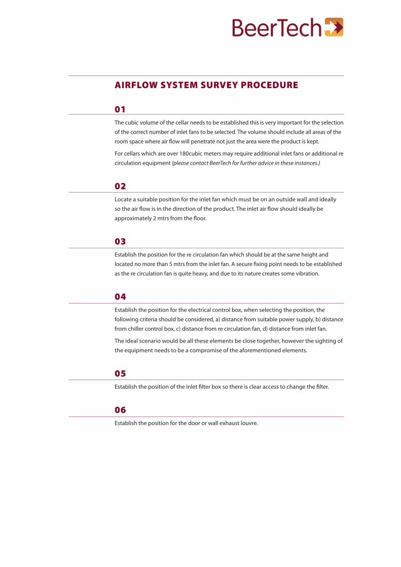
AIRFLOW SYSTEM SURVEY PROCEDURE
01The cubic volume of the cellar needs to be established this is very important for the selection
of the correct number of inlet fans to be selected. The volume should include all areas of the
room space where air flow will penetrate not just the area were the product is kept.
For cellars which are over 180cubic meters may require additional inlet fans or additional re
circulation equipment (please contact BeerTech for further advice in these instances.)
02Locate a suitable position for the inlet fan which must be on an outside wall and ideally
so the air flow is in the direction of the product. The inlet air flow should ideally be
approximately 2 mtrs from the floor.
03Establish the position for the re circulation fan which should be at the same height and
located no more than 5 mtrs from the inlet fan. A secure fixing point needs to be established
as the re circulation fan is quite heavy, and due to its nature creates some vibration.
04Establish the position for the electrical control box, when selecting the position, the
following criteria should be considered, a) distance from suitable power supply, b) distance
from chiller control box, c) distance from re circulation fan, d) distance from inlet fan.
The ideal scenario would be all these elements be close together, however the sighting of
the equipment needs to be a compromise of the aforementioned elements.
05Establish the position of the inlet filter box so there is clear access to change the filter.
06Establish the position for the door or wall exhaust louvre.

AIRFLOW SYSTEM SURVEY REPORT
CUSTOMER DETAILS
BUSINESS NAME: ADDRESS:
CONTACT NAME:
TEL NO:
POST CODE:
SURVEY CHECKLIST
It is important the following information is made available during survey.
1. The total length of the cellar 'L' in metres =
2. The total width of the cellar 'W' in metres =
3. The total height of the cellar 'H' in metres =
4. The total volume square metres L x W x H = Volume =
5. Mark all external walls with 'X' (on diagram below)
6. The thickness of the external wall
7. What material is the building constructed from
8. Convenient location for External Fan and Control Box, mark 'F' and 'B'
9. Location of existing Chiller Fans, mark 'E/C'
10. Power Sockets, marked 'P'
11. Location of doors
SURVEY BY DATE
Comments/Notes
L
W
external wallthickness
tick whendonetick whendone
tick whendonetick whendonetick whendonetick whendone

INSTALLATION INSTRUCTIONS1. Consult the survey report for location of the equipment.
2. The inlet fan equipment- A 150mm clearance hole should be drilled through the external
wall a minimum of two meters from ground level if possible.
The filter and fan assembly should be located by pushing the single 150mm Dia tube
through the pre drilled hole in the wall.
The unit should be fixed to the wall using the tags located on the filter box. The position of
the filter lid should be located to give free access for filter changing
3. The outside duct bend - The duct bend which should be fitted with a vermin guard
should be located into the 150mm dia tube on its exit on the Part No BT-OB04 outside wall
by use of the two tags fitted and sealed with approved mastic or similar material. The bend
must face the ground as it is designed to prevent the system sucking in rain, and the mesh
prevents vermin from entering the unit.
4. The Electrical Control Box - The main control box should be located to the wall using the
four fixing brackets provided
5. The Recirculation Fan (if fitted) - The circulation fan should be located within 5 mtrs of
the inlet equipment the fan should be suspended by means of the support arm part No
BT-SA05 which should be securely fixed to a substantial wall ideally two meters from the
ground. The fan can be directionally pivoted and locked into position which should push
air in the direction of the product.
6. Electrical wiring - All wiring should be carried out using FP200 or equivalent fire rated
cable. Additionally, there should be an external isolation switch between the main power
supply and the control box.
7. Exhaust louvre -This needs to be fitted by drilling a l00mm hole in the wall or door.
The louvre should not be fitted to the outside door if it is designated as a fire door.
8. Probes inner and outer - The outside probe needs to be located on an exterior wall via
a drilled hole and fixed securely. The inside probe needs to be firmly located on an exterior
wall at shoulder height close to the product.

TESTING AND COMMISSIONING OF THE BEERTECH AIR FLOW SYSTEM.The system is designed so that when the outside temperature is 9 degrees or lower the
control box turns the chiller o!. The inlet fan is activated therefore sucking in cold fresh air
at the same time the circulation fan is activated.
If the inside temperature is reduced to 10 degrees or lower the control box will turn o! the
inlet fan but the circulation fan continues to run until the inside temperature rises to 10
degrees or more when the reverse will occur.
TO TEST AND COMMISSIONThe system can be tested by artificially raising or lowering the temperature using chilled
water or an ice cube.
STEP ONE:
If the temperature outside is above 9 degrees, cool the probe to below 9 degrees ,then the
chiller should shut o! and the inlet, and circulation fan should turn on.
To reverse this operation, warm probe with the hand and the opposite will happen.
STEP TWO:
With the inlet fan operating ie) outside temperature below 9 degrees ( naturally or artificially
created) take the internal temperature down to below 10 degrees by cooling the inner
probe.. The circulation fan should be running and the chiller and the external fan should be
shut down. Allow inside temperature to come up to 10 degrees and either the chiller or the
external fan will switch on depending on outside temperature.
With the BeerTech AirFlow system operational, raise the internal probe temperature to above
15°C which will re engage the main chiller. Let the internal temperature then fall below 15°C,
which will turn the chiller o! and revert to the BeerTech AirFlow system.
Check the filter media is fitted.
Check the service engineer will have clear access to the filter lid.
Check the desired temperature settings via the PCB instructions.

AIR FLOW SETTINGS INFORMATION.MAIN INTERFACE:
When the temperature controller is supplied with power, it starts running. It will first read the
mode values from itself. The controller has three running modes. These three running modes
are automatic controlling mode, isolator mode and o! mode.
When the controller is in automatic mode, it automatically controls the indoor fan,
outdoor fan and indoor chiller to run or stop in accordance with the indoor and outdoor
temperature. When the controller is in isolator mode, it will run the indoor fan and indoor
chiller, and make the outdoor fan stop in spite of the indoor or outdoor temperature. When
the controller is in o! mode, the indoor fan, indoor chiller, and outdoor fan are all stopped.
When the controller is running, it displays the main interface as following figure 1.
DISPLAYS OF STATUS, TOTAL TIME AND RATION:
In the top rectangle, the display indicates the running status of the indoor fan, outdoor fan
and indoor chiller in the status column. For example, when the indoor fan is running, we
can see that blades of the red fan are rotating at the corresponding status position. If the
indoor fan is stopped, we can see that the red fan blades are static at the corresponding
status position. This also applies to the Indoor Chiller and Outdoor Fan.
At the same time, the controller displays the total running time of indoor fan, outdoor fan
and indoor chiller individually at the total time column. For example, when the indoor fan
is running, the total time of indoor fan will increase second by second.
At the same time, the controller computes the ratios of indoor fan, outdoor fan and indoor
chiller running percentages. For example, the ratio of the indoor fan running time is worked
out through total running time of the indoor fan, divided by the total running time of the
controller.
nameindoor fanindoor chilleroutdoor fan
indoor temperature
outdoor temperature
0:00:000:00:000:00:00
0.00%0.00%0.00%
status total time ratio
10ºC
2012-10-08
08:08:00
Start time 11:00autoEnd time 12:00
9ºC
12ºC10ºC
figure 1

AIR FLOW SETTINGS INFORMATION.DISPLAYS OF INDOOR & OUTDOOR TEMPERATURE:
The middle rectangle displays the current indoor and outdoor temperature on the right of
the panel. The temperatures displayed on the left indicate the settings that the controller
will activate and deactivate the AirFLow fan and main cellar chiller.
When the controller is in automatic mode, it automatically controls the indoor fan,
outdoor fan and indoor chiller to run or stop in accordance with the indoor and outdoor
temperature. When the controller is in isolator mode, it will run the indoor fan and indoor
chiller, and make the outdoor fan stop in spite of the indoor or outdoor temperature. When
the controller is in o! mode, the indoor fan, indoor chiller, and outdoor fan are all stopped.
When the controller is running, it displays the main interface as following figure 1.
DISPLAYS OF CALENDAR, START & END TIME AND RUNNING MODE:
The bottom rectangle displays the calendar, start and stop time for the main cellar chiller
and the mode of controller.
The start and stop time for the indoor chiller is used for controlling the chiller to run or
stop. When the time arrives at the set starting time, the indoor chiller starts to run in spite
of indoor or outdoor temperature, even if the controller is in automatic mode. When the
time arrives at the set ending time, the indoor chiller will return to being controlled by the
indoor or outdoor temperature.
That is to say, the indoor chiller must run between start and end time every day when the
controller is in automatic mode or isolator mode. The start and stop time for this can be
adjusted to suit personal preferences by keyboard operation. If you prefer that the indoor
chiller does NOT run forcibly, please set start and end time to the same.
KEYBOARD OPERATION:
Keyboard introduction
The controller has nine keys. These keys are left arrow key, right arrow key, up arrow key,
down arrow key, setting key (SET), Enter key (ENT), isolator key (ISOLATOR), automatic key
(AUTO), and o! key (OFF).
Setting of indoor and outdoor temperature value
We can set the preferred indoor and outdoor temperature by keyboard operation.
First, push the [SET] key, and the following function interface will display, as per figure 2
overleaf.

AIR FLOW SETTINGS INFORMATION.KEYBOARD OPERATION:
Keyboard introduction
The controller has nine keys. These keys are left arrow key (�), right arrow key (�), up arrow
key (�), down arrow key (�), setting key (SET), Enter key (ENT), isolator key (ISOLATOR),
automatic key (AUTO), and o! key (OFF).
Setting of indoor and outdoor temperature value
We can set the preferred indoor and outdoor temperature by keyboard operation. First,
push the [SET] key, and the following function interface will display, as per figure 2 below.
If we select item 1, the interface setting of indoor and outdoor temperature will display
as per figure 3 above. We can select the item which we will modify through the up and
down arrow key. When we have determined the item which we will modify, then push
ENT key, and the item will become red. At that time, push the up arrow key, down arrow
key, left arrow key and right arrow key in order to modify the number. Pushing the left
key will increase the number by 1 and pushing the right key will decrease the number
by 1. When the required values have been set, push the ENT key, and then push the SET
key, the controller will save the values. The again push the SET key, and the display will
return to the main interface.
Function choice
1.temperature setting
2.date and time adjusting
3.chiller working time
4.temperature unit choice
5.initializing total time
6.sensor adjusting
Temperature setting
1.indoor temperature 10.0
2.outdoor temperature 9.0
figure 2 figure 3

AIR FLOW SETTINGS INFORMATION.KEYBOARD OPERATION:
Date and time adjusting
We can adjust date and time by keyboard operation. First, push the [SET] key, and go into
the following display by selecting no.2 as per figure 2 using the up or down arrows. Then
select the item you would like to adjust by again using the down or up arrow arrows, then
push the ENT key, and go into the adjusting interface of date and time as per figure 4.
We can the select the item which we will modify by using the up arrow and down arrow
key. When we have determined the item which we will modify, then push the ENT key, and
the item will become red. At that time, we can push the up, down, left or right arrow key
in order to change the number. Pushing the down arrow key, will decrease the number by
1 and pushing the up arrow key will increase the number by 1. Pushing the left key, the
number will increase by 10 and pushing the right key will decrease by the number by 10.
When the desired values have been reached, push the ENT key, then push the SET key. The
controller will save the values. Push the SET key again to return to the main interface.
NOTICE: On the main interface, since the total time and ratio is calculated by the time,
if the time was adjusted, the total time and ratio would be inaccurate. Please refer to
section 3.2.6 and figure 7 to initialize the total time, and the total time and ratio will be
re-calculated.
figure 4
Date and time adjusting
Year: 2012
Month: 10
Day: 08
Hour: 08
Minute: 00
Second: 00
AIR FLOW SETTINGS INFORMATION.KEYBOARD OPERATION:
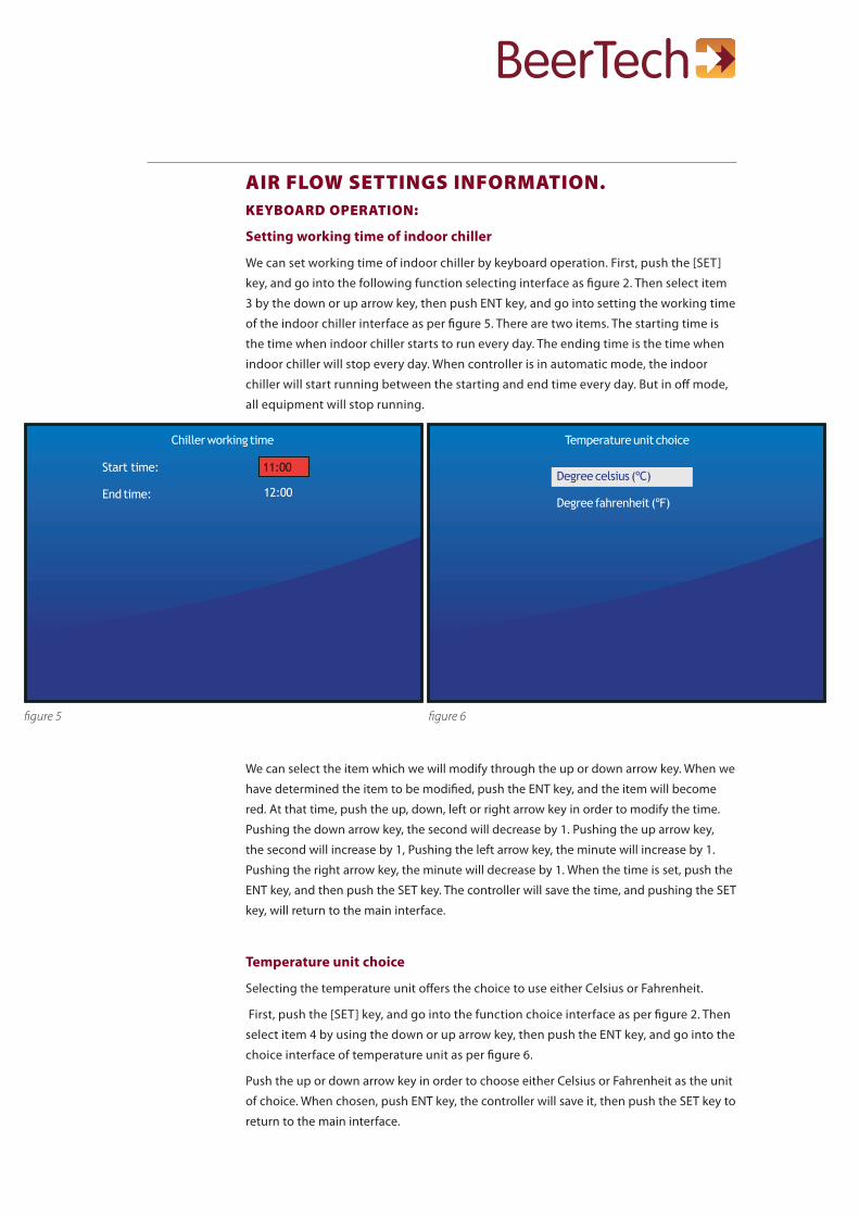
Setting working time of indoor chiller
We can set working time of indoor chiller by keyboard operation. First, push the [SET]
key, and go into the following function selecting interface as figure 2. Then select item
3 by the down or up arrow key, then push ENT key, and go into setting the working time
of the indoor chiller interface as per figure 5. There are two items. The starting time is
the time when indoor chiller starts to run every day. The ending time is the time when
indoor chiller will stop every day. When controller is in automatic mode, the indoor
chiller will start running between the starting and end time every day. But in o! mode,
all equipment will stop running.
We can select the item which we will modify through the up or down arrow key. When we
have determined the item to be modified, push the ENT key, and the item will become
red. At that time, push the up, down, left or right arrow key in order to modify the time.
Pushing the down arrow key, the second will decrease by 1. Pushing the up arrow key,
the second will increase by 1, Pushing the left arrow key, the minute will increase by 1.
Pushing the right arrow key, the minute will decrease by 1. When the time is set, push the
ENT key, and then push the SET key. The controller will save the time, and pushing the SET
key, will return to the main interface.
Temperature unit choice
Selecting the temperature unit o!ers the choice to use either Celsius or Fahrenheit.
First, push the [SET] key, and go into the function choice interface as per figure 2. Then
select item 4 by using the down or up arrow key, then push the ENT key, and go into the
choice interface of temperature unit as per figure 6.
Push the up or down arrow key in order to choose either Celsius or Fahrenheit as the unit
of choice. When chosen, push ENT key, the controller will save it, then push the SET key to
return to the main interface.
figure 5 figure 6
Chiller working time
Start time: 11:00
End time: 12:00
Temperature unit choice
Degree celsius (ºC)
Degree fahrenheit (ºF)
AIR FLOW SETTINGS INFORMATION.KEYBOARD OPERATION:
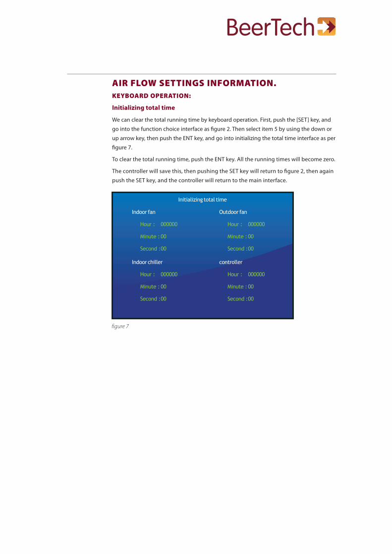
Initializing total time
We can clear the total running time by keyboard operation. First, push the [SET] key, and
go into the function choice interface as figure 2. Then select item 5 by using the down or
up arrow key, then push the ENT key, and go into initializing the total time interface as per
figure 7.
To clear the total running time, push the ENT key. All the running times will become zero.
The controller will save this, then pushing the SET key will return to figure 2, then again
push the SET key, and the controller will return to the main interface.
figure 7
Initializing total time
Indoor fan
Hour : 000000
Minute : 00
Second : 00
Indoor chiller
Hour : 000000
Minute : 00
Second : 00
Outdoor fan
Hour : 000000
Minute : 00
Second : 00
controller
Hour : 000000
Minute : 00
Second : 00
AIR FLOW SETTINGS INFORMATION.KEYBOARD OPERATION:
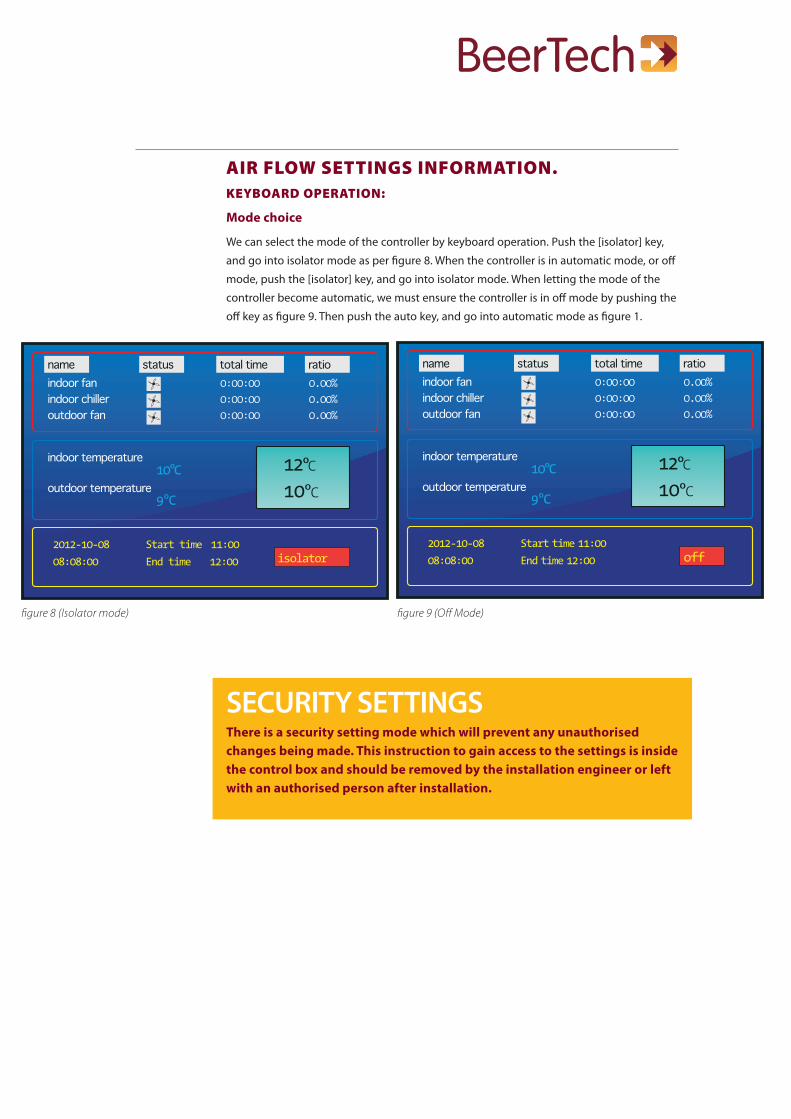
Mode choice
We can select the mode of the controller by keyboard operation. Push the [isolator] key,
and go into isolator mode as per figure 8. When the controller is in automatic mode, or o!
mode, push the [isolator] key, and go into isolator mode. When letting the mode of the
controller become automatic, we must ensure the controller is in o! mode by pushing the
o! key as figure 9. Then push the auto key, and go into automatic mode as figure 1.
SECURITY SETTINGSThere is a security setting mode which will prevent any unauthorised changes being made. This instruction to gain access to the settings is inside the control box and should be removed by the installation engineer or left with an authorised person after installation.
figure 8 (Isolator mode) figure 9 (O! Mode)
nameindoor fanindoor chilleroutdoor fan
indoor temperature
outdoor temperature
0:00:000:00:000:00:00
0.00%0.00%0.00%
status total time ratio
10ºC
2012-10-08
08:08:00
Start time 11:00isolatorEnd time 12:00
9ºC
12ºC10ºC
nameindoor fanindoor chilleroutdoor fan
indoor temperature
outdoor temperature
0:00:000:00:000:00:00
0.00%0.00%0.00%
status total time ratio
10ºC
2012-10-08
08:08:00
Start time 11:00offEnd time 12:00
9ºC
12ºC10ºC

SERVICE INFORMATION1. The engineer should open the filter air expansion box and remove the filter sheet, The
chamber should be inspected for any filter waste insects and solids and cleaned accordingly.
2. Fit new filter.
3. The system should be tested for function by warming and cooling the probes as
described within the Testing and Commissioning procedure on page 6.
For all service requirements please contact:
Note- Between the hours of 11 AM and noon (wintertime) and Noon and 1.00 PM.
(summertime) as the micro computer shuts the BeerTech system over to chiller only mode
during this period. There is a green light on the Micro computer which when on shows
when the system is in the chiller only mode.
If there is any malfunction the main power switch should be turned OFF which will close
the AirFlow System down will revert power to normal internal chillers.
THEN call the contact number below for attention.
Service and maintenance
THE PCB DISPLAY WILL SHOW IN REAL TIME THE DURATION EACH FAN HAS RUN AND WILL AUTOMATICALLY RECORD THE %. IT IS EASY TO CONVERT THESE FIGURES INTO THE EXACT RUNNING COST ASSOCIATED WITH EACH APPLICATION.
WARNING 240 VOLTS
The control box should only be opened by a qualified electrician.
The control box should be locked at all times and the key held by an authorised person.

BEERTECH ARM MICRO CONTROLLER SYSTEM
L N E ARTH E ARTH E ARTH EARTH
230 V AC 13 A MA X SUPPL Y VIA SW ITCHED FUSED SPURE
X 3 & X 4TERMINALS NOT USED
OUTDOOR F ANSF AN 1 & F AN 1AFOR PULLING COLD AIR INTOCELL AR
INDOOR F ANSF AN 2 & F AN 2AFOR CIRCUL A TINGAIR IN CELL AR
N N N
NETUR AL
V OL T FREE NCCONT ACTS R A TED5 A MA X FOR BRE AKINGSUPPL Y TO CHILLER ST A TOR DIRECT TO CONTROL CIRCUIT
K1 REL A Y FOROPER A TING OUTDOOR F ANSF ANS 1 & 1AFOR PULLINGIN COLD AIR INTO CELL AR
K 2 REL A Y FOROPER A TING INDOORF ANS 2 & 2 AFOR CIRCUL A TINGCOLD AIR IN CELL AR
K 3 NC 5 A MA X CONT ACTTO BE W IRED DIRECT TOCHILLER ST A T OR CONTROL.W HEN AIRFLOW SYSTEMIS OFF K 3 NORMALL Y CLOSEDCONT ACTS W ILL ALLOW CHILLERTO W ORK AS NORMAL
K 3 NORMALL Y CLOSEDCONT ACTS, W IRED TO CHILLER CONTROL CIRCUIT. W IRE SO W HENAIRFLOW SYSTEM IS OFFTHE CHILLER W ILL OPER A TENORMAL.
2 A FUSE 10 A FUSE 10 A FUSEINDOORPROBE
OUTDOORPROBE
W ARNINGSHOCK HA Z ARD. DO NOT OPEN THIS P ANELUNLESS MAINS POWER SUPPL Y & ALTERNA TIVEPOWER SUPPL Y HA VE BEEN ISOL A TED.
TERMINALS MA Y CONT AIN SWITCHED 230V AC LIVES FROM MAIN CHILLER. THIS P ANEL IS SINGLE PHASE AND MUST NOT BE WIRED TO MIXED PHASES.
CELL AR AIR FLOW SYSTEMCONTROL P ANEL DR A W ING
GW WR A TINGSINPUT SUPPL Y 230 V AC 13 A MA XOUTPUT F ANS 230 V AC TOT AL 10 A MA XNC CHILLER CONT ACT 5 A MA X
1.5mm
P ANEL AND P ANEL DOOR MUST BE E ARTHED
230 V AC
T1 T2 T3 T 4 T5 T6
RED YE
LLO
W
WHI
TE
RED YE
LLO
W
WHI
TE
12V AC / 5V ATR ANSFORMER
+/ -12V AC
12 13 11
1
18
1 1
5 6
1
1
1
2 2 2
21
5 5 6 6
9 107 8
15
14
17
16
NOTE ON POW ER R A TINGSW HEN INST ALLED W ITH ONE OUTDOOR F AN AND ONE INDOOR F AN P ANELS TOT AL POW ER IS APPRO X 500WFOR EACH F AN ASSEMBL Y ADDED, ADD APPRO X 250W
OU
TDO
OR
FAN
1 L
IVE
OU
TDO
OR
FAN
2 L
IVE
IND
OO
R F
AN
1 L
IVE
IND
OO
R F
AN
2 L
IVE
THE BEERTECH AIR FLOW SYSTEM IS COPYRIGHTED, REGISTERED AND P A T PENDING
K 3
SEE W ARNIGS AND INSTRUCTIONSON P AGE 5 BEFORE INST ALLING

AIR FLOW SYSTEM
BEERTECH ARM MICROSYSTEM CONTROLLER
P ANELDOOR LOCK
X1 = 230 V AC 13 A LIVE SUPPL Y TO P ANEL
X2 = NEUTR AL SUPPL Y TO P ANEL
E = EARTH TO PANEL
X3 & X 4 = NOT USED CHILLER W HEN OUTSIDE TEMP DROPS TO BELOW 10C
X7 = OUTDOOR F AN 1 OUTPUT 230 V AC TO ALLOW COLD AIR TO BE PULLED INSIDE CHELL AR FROM OUTSIDE
X8 = OUTDOOR F AN 2 (OPTION TO ADD SECOND F AN)
X9 = INDOOR F AN 1 OUPUT 230V AC TO OPER A TE CELL AR AIR CIRCUL A TION F AN
X10 = INDOOR F AN 2 (OPTION TO ADD SECOND F AN)
X14 & X15 = NC CONT ACT (5 A MA X) VOLT FREE CONT ACT TO BE W IRED DIRECT TO CHILLER ST A T OR CONTROL CIRCUIT
X16 & X17 = AUX NC CONT ACT (5 A VOLT FREE CONT ACT TO BE W IRED DIRECT TO CHILLER ST A T OR CONTROL CIRCUIT
X14,X15 OR X16,X17W IRE THE 5 A NC CONT ACT DIRECT INTO THE CHILLER ST A T OR CHILLER CONTROL CIRCUIT TO STOP THE CHILLER B Y THE NC CONT ACTS OPENING .
R A TINGSINPUT SUPPL Y 230V AC 13 A MA XOUTPUT F ANS 230 V AC TOT AL 10 A MA XNC CHILLER CONT ACT 5 A MA X
R A TINGSINPUT SUPPL Y 230 V AC 13 A MA XOUTPUT F ANS 230 V AC TOT AL 10 A MA XNC CHILLER CONT ACT 5 A MA X
CELL AR AIR FLOW SYSTEMCONTROL P ANEL DR A W ING
GW W
INST ALL A TION W ARNINGS:BEFORE COMMENCING INST ALL A TION ISOL A TE YOUR MAINS ELECTRIC SUPPL Y
This pr oduc t should be ins talled in ac cor danc e w i th the r elevant sec t ions o f the building r egula t ions c ode and the cur r ent edi t ion o f the IEE W ir ing Regula t ions (BS 7671:Requir ements f or elec tr ical ins talla t ions) and appr opr ia te s ta tu tor y r egula t ions.
Hea t ing & cooling sys tems ar e c lassed as spec ial ins talla t ions and mus t be cer t i f ied by an appr o vedc ompe tent elec tr ic al c ontr ac tor conf orming t o Par t P, r equir ements o f BS 7671:2001 and appr opr ia te s ta tutor y r egula t ions.
As o f Apr il 2004, ne w ins talla t ions in the UK should be w ir ed using the EU harmonised c olour s f or the supply c onduc tor s.
NEW COLOURS: BROW N = Live BLUE = Neutr al YELLOW / GREEN = Ear th
THE BEERTECH AIR FLOW SYSTEM IS COPYRIGHTED, REGISTERED AND P A T PENDING
P ANEL TO BE KEPTLOCKED A T ALL TIMES
W ARNINGSHOCK HA Z ARD. DO NOT OPEN THIS P ANELUNLESS MAINS POWER SUPPL Y & ALTERNA TIVEPOWER SUPPL Y HA VE BEEN ISOL A TED.
TERMINALS MA Y CONT AIN SWITCHED 230V AC LIVES FROM MAIN CHILLER. THIS P ANEL IS SINGLE PHASE AND MUST NOT BE WIRED TO MIXED PHASES.
SEE W ARNIGS AND INSTRUCTIONSON P AGE 5 BEFORE INST ALLING
SET ENT
ISOLA TOR AUTO
OFF
GREENINDOOR F AN
YELLOWCHILLER
REDOUTDOOR F AN
TIMER / TEMPER A TURE CONTROLLER
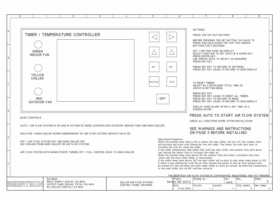
B ASIC CONTROLS
AUTO = AIR FLOW SYSTEM IS ON AND IN AUTOMA TIC MODE (CONTROLLING OUTDOOR, INDOOR F ANS AND MAIN CHILLER)
ISOL A TOR = MAIN CHILLER W ORK S INDEPEND ANT OF AIR FLOW SYSTEM. INDOOR F AN IS ON
OFF = AIR FLOW SYSTEM OFF AND MAIN CHILLER OFF(NO COOLING FROM MAIN CHILLER OR AIR FLOW SYSTEM)
AIR FLOW SYSTEM W ITH MAINS POW ER TURNED OFF = FULL CONTROL B ACK TO MAIN CHILLER
SET TINGS
PRESS THE OFF BUTTON FIRST
BEFORE PRESSING THE SET BUT TON YOU HA VE TOPRESS AND HOLD DOW N THE TOP T W O ARROW BUT TONS FOR 5 SECONDS.
SET = SET TING P AGE ON DISPL A Y.SELECT FUNCTION TO SET W ITH UP & DOW N KEY.PRESS ENTER KEY.USE ARROW KEYS TO SELECT AS REQUIRED.PRESS ENT KEY.
PRESS SET KEY TO RETURN TO SET TINGS.PRESS SET KEY AGAIN TO RETURN TO MAIN DISPL A Y
TO RESET TIMERS SELECT No 5 INITIALIZING TOT AL TIME AS ABO VE IN SETTING MENU PRESS ENT KEY.PRESS ENT KEY AGAIN TO RESET ALL TIMERSPRESS SET KEY TO RETURN TO MENUPRESS SET KEY AGAIN TO RETURN TO MAIN DISPL A Y
DISPL A Y GOES BL ANK AFTER A SET TIME AS ASCREEN S A VER
CELL AR AIR FLOW SYSTEMCONTROL P ANEL DR A W ING
GW W
Oper a t ional SequenceW hen the out side t emp f alls t o 9C or belo w the main chiller w ill turn o f f , the out door f ans w ill ac t iva te and dr a w c ool f il t er ed air in t o the c ellar . The indoor f an w i th also s tar t t o c ir cula te the cool air r ound the c ellar .If the c ellar t emper a tur e f alls belo w 10C, bo th the main chiller and outdoor f ans shut do wn, jus t lea ving the indoor f ans t o c ir cula te the cellar air .W hen the out side t emp r ises abo ve 9C the outdoor f ans and indoor c ir cula t ion f ans shut do wn and the main c ellar chiller is r eac t iva ted.If the c ellar t emp r ises above 15C the main chiller w ill r e -s tar t & s t op when temp dr ops t o 13C.If ther e is any mal f unc t ion w i th the air f lo w sys tem the po w er t o the air f lo w sys tem mus t be turned o f f , this w ill allo w the main cellar chiller t o w ork as normal. All elec t r ic al c onnec t ions t o the main chiller ar e v ia NC vol t f r ee contac t s.
THE BEERTECH AIR FLOW SYSTEM IS COPYRIGHTED, REGISTERED AND P A T PENDINGR A TINGSINPUT SUPPL Y 230 V AC 13 A MA XOUTPUT F ANS 230 V AC TOT AL 10 A MA XNC CHILLER CONT ACT 5 A MA X
PRESS AUTO TO ST AR T AIR FLOW SYSTEMCHECK ALL FUNCTIONS W ORK AFTER INST ALL A TION
SEE W ARNIGS AND INSTRUCTIONSON P AGE 5 BEFORE INST ALLING
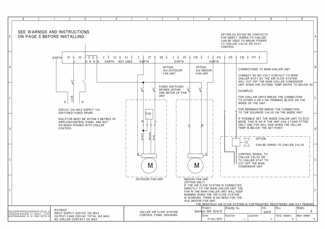
L N E ARTH E ARTH E ARTH E ARTH
230V AC 13 A MA X SUPPL Y VIA SW ITCHED FUSED SPURE
ISOL A TOR MUST BE W ITHIN 2 METRES OF AIRFLOW CONTROL P ANEL AND NOTON MIXED PHASES W ITH CHILLERCONTROL.
N N N
BLUE
BLA
CK
BRO
WN
N L
C AP
M
OUTDOOR F AN UNIT
OPTION2nd OUTDOORF AN UNIT
OPTION2nd INDOORF AN UNIT
M
L N
INDOOR F AN UNIT(OPTION ONL Y)IF THE AIR FLOW SYSTEM IS CONNECTED DIRECTL Y TO THE MAIN CHILLER UNIT THE F AN IN THE MAIN CHILLER UNIT W ILL KEEPRUNNING W HEN THE AIR FLOW SYSTEMIS W ORKING. THERE IS NO NEED FOR THE AUX INDOOR F AN UNIT.
EE
CELL AR AIR FLOW SYSTEMCONTROL P ANEL DR A W ING
OPTION 5 A R A TED NC CONT ACTSFOR DIRECT W IRING TO CHILLER.C AN BE USED TO BRE AK POW ER TO CHILLER V AL VE OR ST A TCONTROL
GW W
LIV
E
N
CONTROL SIGNAL TOCHILLER V AL VE OR TO CHILLER ST A T TOCUT OFF THE MAINCONDENSOR UNIT
E ARTH
E
THE BEERTECH AIR FLOW SYSTEM IS COPYRIGHTED, REGISTERED AND P A T PENDING
R A TINGSINPUT SUPPL Y 230 V AC 13 A MA XOUTPUT F ANS 230 V AC TOT AL 10 A MA XNC CHILLER CONT ACT 5 A MA X
CONNECTIONS TO MAIN CHILLER UNIT
CONNECT NC NO VOL T CONT ACT TO MAINCHILLER ST A T SO THE AIR FLOW SYSTEMW ILL CUT OFF THE MAIN CHILLER CONDENSOR UNIT W HEN THE OUTSIDE TEMP DROPS TO BELOW 9C.
EX AMPLES
FOR CHILL AIR UNITS BRE AK THE CONNECTION TO EITHER 5 OR 6 ON TERMINAL BLOCK ON THEINSIDE OF THE UNIT.
FOR BEERMASTER BREAK THE CONNECTION TO THE SOLENOID V AL VE ON THE INSIDE UNIT.
IF POSSIBLE SET THE INSIDE CHILLER UNIT TO ECOMODE. THIS IS SO IF THE UNIT HAS 3 F ANS FIT TEDONL Y ONE F AN W ILL RUN W HEN THE CELL ARTEMP IS BELOW THE SET POINT.
FUSED SW ITCHEDSPURES W ITHIN ONE METER OF F ANUNIT
NOT USED
OPTION
C AN BE W IRED TO CHILLER V AL VE
SEE W ARNIGS AND INSTRUCTIONSON P AGE 5 BEFORE INST ALLING

R A TINGSINPUT SUPPL Y 230 V AC 13 A MA XOUTPUT F ANS 230 V AC TOT AL 10 A MA XNC CHILLER CONT ACT 5 A MA X
CELL AR AIR FLOW SYSTEMCONTROL P ANEL DR A W ING
GW W
AIRFLOW SYSTEM INST ALL A TION NOTES
Dif f er ent br e w er ies may have di f f er ent methods f or ins talling and using the air f lo w sys tem within the c ellarSelec t ion o f common ins talla t ion methods.
1. Air f lo w contr ol panel po w er supply is f ed f r om the same supply tha t is used f or the c ellar chiller uni t. A contr ol volt age is wir ed f r om the c ellar chiller t o the Air f lo w contr ol panel.Note: In this case the Air f lo w contr ol panel should be within 2 metr es o f the c ellar contr ol panel isola tor . If the air f lo w panel is no t within 2 metr es a second isola tor is r equir ed f or the air f lo w panel, ei ther via a 13 A plug and sock et or a 13 A s wit ched f used spur.
2. Air f lo w contr ol panel po w er supply is supplied via a 13 A sock et or 13 A s wit ched f used spur within the c ellar . The chiller contr ol volt age is dir ec t ly wir ed to the Air f lo w contr ol panel f r om the chiller contr ol panel.Note: With this method the Air f lo w contr ol panel mus t be c lear ly mark ed with a warning label s t a t ing ‘Warning mult iple supplies’This label mus t be mark ed with the point o f isola t ion f or the mains po w er supply and the alt erna t ive po w er supply point ( which is normally the c ellar chiller c ontr ol panel po w er supply).
3. Air f lo w contr ol panel po w er supply is supplied via a 13 A sock et or 13 A s wit ched f used spur with in the c ellar . Ther e is no dir ec t connec t ion to the c ellar chiller .Note: With this method the Air f lo w sys tem is t o t ally independent o f the c ellar chiller . This method r equir es the air f lo w panel se t t ings to have a t emper a tur e di f f er ent ial o f one to t w o degr ees lo w er than the main c ellar chiller se t point t emper a tur e. Ho w this w ork s is: as the out side t emper a tur e dr ops to i t s se t point ( tha t is lo w erthan the c ellar main chiller ) the c ellar t emper a tur e dr ops and the main chiller then cut s out when i t s se t point isr eached. The air f lo w sys tem will c ont inue to cool the c ellar with na tur al cold air f r om out side. This method canbe used i f you do not want t o int er f er e with the main c ellar chiller c ontr ol panel. Or i f the c ellar chiller also has aheat ing c ir cuit.
S AFET Y W ARNING NOTE ON WIRING
THE AIRFLOW CONTROL P ANEL POWER SUPPL Y IS SINGLE PHASE AND MUST BE ON THE S AME PHASE AS THE MAIN CHILLER CONTROL P ANEL