Embed Size (px)
Citation preview

Beckhoff PC Fieldbuscard PCI CANopen FC5101 and FC5102
Last change: 31.10.2002
CANopen PCI Card FC5101, FC5102


Eiserstraße 5 / D-33415 Verl / Telefon 05246/963-0 / Telefax 05246/963-149
3
Contents
CANopen PCI Card FC5101, FC5102 1. Foreword 5
Notes on the Manual 5 Safety Instrutions 6 Version of the Documentation 7
2. Product Overview 8 Technical Documentation 8 CANopen Introduction 9 Hardware Description 11
3. Fitting and wiring 13 Installation 13 Wiring the Bus System 14
4. Parameterisation and Commissioning 20 Configuration: TwinCAT System Manager 20 Beckhoff Bus Coupler 28 CANopen Device 30 CANopen eds Files 34
5. CANopen Communication 35 Network Management 35 BootUp of the FC510x 39 Process data Objects (PDO) 42 PDO Parameterisation 49 Service data objects 51 FC501x: SDO Communication 55 Baud rate and Bit Timing 60 Identifier Allocation 61
6. Error Handling and Diagnosis 62 LEDs 62 Bus Node Diagnostics 63 Diagnostics FC510x 66 Emergency Messages 68 ADS error codes 69

Eiserstraße 5 / D-33415 Verl / Telefon 05246/963-0 / Telefax 05246/963-149
4
Trouble Shooting 73
7. Bus Trace Function 76 FC510x as a CANopen Monitor 76
8. Appendix 83 Identifier Full List 83 License 92 List of Literature 93 List of Abbreviations 94 Support 95
Eiserstraße 5 / D-33415 Verl / Telefon 05246/963-0 / Telefax 05246/963-149
5
1. Foreword Notes on the Manual
This description is only intended for the use of trained specialists in control and automation engineering who are familiar with the applicable national standards. It is essential that the following notes and explanations are followed when installing and commissioning these components.
Liability Conditions The responsible staff must ensure that the application or use of the products described satisfy all the require-ments for safety, including all the relevant laws, regulations, guidelines and standards.
The documentation has been prepared with care. The products described are, however, constantly under de-velopment. For that reason the documentation is not in every case checked for consistency with performance data, standards or other characteristics, and does not represent an assurance of characteristics in the sense of § 459, Para. 2 of the German Civil Code. In the event that it contains technical or editorial errors, we retain the right to make alterations at any time and without warning. No claims for the modification of products that have already been supplied may be made on the basis of the data, diagrams and descriptions in this documentation.
© This manual is copyrighted. Any reproduction or third party use of this publication, whether in whole or in part, without the written permission of Elektro Beckhoff GmbH, is forbidden.
Eiserstraße 5 / D-33415 Verl / Telefon 05246/963-0 / Telefax 05246/963-149
6
Safety Instructions
Safety Rules The responsible staff must ensure that the application or use of the products described satisfy all the require-ments for safety, including all the relevant laws, regulations, guidelines and standards.
State at Delivery All the components are supplied in particular hardware and software configurations appropriate for the applica-tion. Modifications to hardware or software configurations other than those described in the documentation are not permitted, and nullify the liability of Elektro Beckhoff GmbH.
Personnel Qualification This description is only intended for the use of trained specialists in control and automation engineering who are familiar with the applicable national standards.
Description of safety symbols The following safety symbols are used in this operating manual. They are intended to alert the reader to the associated safety instructions.
Danger
This symbol is intended to highlight risks for the life or health of personnel.
Warning
This symbol is intended to highlight risks for equipment, materials or the environment.
Note
This symbol indicates information that contributes to better understanding.

Eiserstraße 5 / D-33415 Verl / Telefon 05246/963-0 / Telefax 05246/963-149
7
Version of the Documentation Version Changes 0.9 (Pre-Release) Prelimary Version, 11.3.2002
1.0 completely revised - FC510x Monitor Software documented - CANopen Protocol description revised
The using of the FC5101 in the slave mode is described separately (FC510x Slave.chm resp. -.pdf).
Eiserstraße 5 / D-33415 Verl / Telefon 05246/963-0 / Telefax 05246/963-149
8
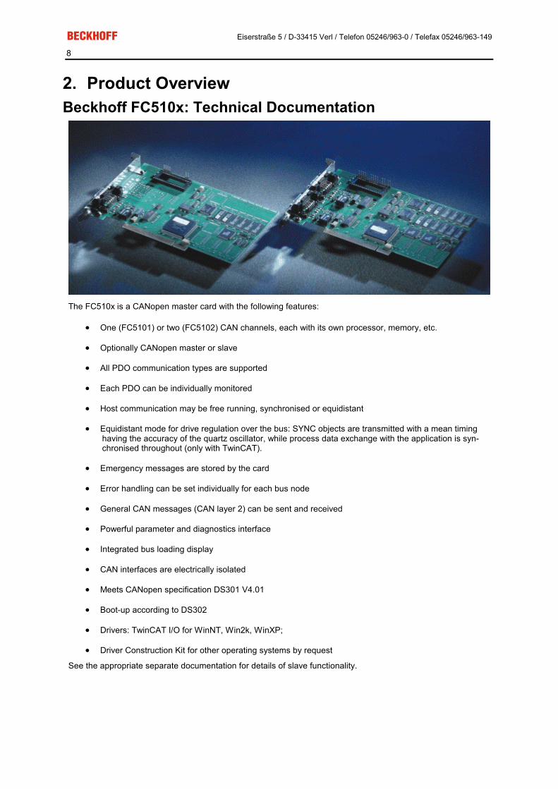
2. Product Overview Beckhoff FC510x: Technical Documentation
The FC510x is a CANopen master card with the following features:
�� One (FC5101) or two (FC5102) CAN channels, each with its own processor, memory, etc.
�� Optionally CANopen master or slave
�� All PDO communication types are supported
�� Each PDO can be individually monitored
�� Host communication may be free running, synchronised or equidistant
�� Equidistant mode for drive regulation over the bus: SYNC objects are transmitted with a mean timing having the accuracy of the quartz oscillator, while process data exchange with the application is syn-chronised throughout (only with TwinCAT).
�� Emergency messages are stored by the card
�� Error handling can be set individually for each bus node
�� General CAN messages (CAN layer 2) can be sent and received
�� Powerful parameter and diagnostics interface
�� Integrated bus loading display
�� CAN interfaces are electrically isolated
�� Meets CANopen specification DS301 V4.01
�� Boot-up according to DS302
�� Drivers: TwinCAT I/O for WinNT, Win2k, WinXP;
�� Driver Construction Kit for other operating systems by request
See the appropriate separate documentation for details of slave functionality.

Eiserstraße 5 / D-33415 Verl / Telefon 05246/963-0 / Telefax 05246/963-149
9
CANopen Introduction CANopen is a widely used CAN application layer, developed by the CAN in Automation association, and which has meanwhile been adopted for international standardisation.
Device Model CANopen consists of the protocol definitions (communication profile) and of the device profiles that standardise the data contents for the various device classes. Process data objects (PDO).are used for fast communication of input and output data. The CANopen device parameters and process data are stored in a structured object directory. Any data in this object directory is accessed via service data objects (SDO). There are, additionally, a few special objects (such as telegram types) for network management (NMT), synchronisation, error messages and so on.
Communication Types CANopen defines a number of communication classes for the input and output data (process data objects):
�� Event driven: Telegrams are sent as soon as their contents have changed. This means that the proc-ess image as a whole is not continuously transmitted, only its changes.
�� Cyclic synchronous: A SYNC telegram causes the modules to accept the output data that was previ-ously received, and to send new input data.
�� Requested: A CAN data request telegram causes the modules to send their input data.
The desired communication type is set by the "Transmission Type" parameter.
Device Profile The Beckhoff CANopen devices support all types of I/O communication, and correspond to the device profile for digital and analog input/output modules (DS401).
The default mapping has not been adapted to the profile version DS401 V2 because of the downward compati-bility.
Transmission Rates Nine transmission rates from 10 kbaud up to 1 Mbaud are available for different bus lengths. The effective utili-sation of the bus bandwidth allows CANopen to achieve short system reaction times at relatively low data rates.

Eiserstraße 5 / D-33415 Verl / Telefon 05246/963-0 / Telefax 05246/963-149
10
Topology CAN is based on a linear topology. The number of devices participating in each network is logically limited by CANopen to 128, but physically the present generation of drivers allows up to 64 nodes in one network seg-ment. The maximum possible size of the network for any particular data rate is limited by the signal transit time required on the bus medium. For 1 Mbaud, for instance, the network may extend 25 m, whereas at 50 kbaud the network may reach up to 1000 m. At low data rates the size of the network can be increased by repeaters, which also allow the construction of tree structures.
Bus access procedures CAN utilises the Carrier Sense Multiple Access (CSMA) procedure, i.e. all participating devices have the same right of access to the bus and may access it as soon as it is free (multi-master bus access). The exchange of messages is thus not device-oriented but message-oriented. This means that every message is unambiguously marked with a prioritised identifier. In order to avoid collisions on the bus when messages are sent by different devices, a bit-wise bus arbitration is carried out at the start of the data transmission. The bus arbitration assigns bus bandwidth to the messages in the sequence of their priority. At the end of the prioritisation phase only one bus device occupies the bus, collisions are avoided and the bandwidth is optimally exploited.
Configuration and parameterisation The TwinCAT System Manager allows all the CANopen parameters to be set conveniently. An "eds" file (an electronic data sheet) is available on the Beckhoff website for the parameterisation of Beckhoff CANopen de-vices using configuration tools from other manufacturers.
Certification The Beckhoff CANopen devices have a powerful implementation of the protocol, and are certified by CiA, the CAN in Automation association.
Eiserstraße 5 / D-33415 Verl / Telefon 05246/963-0 / Telefax 05246/963-149
11
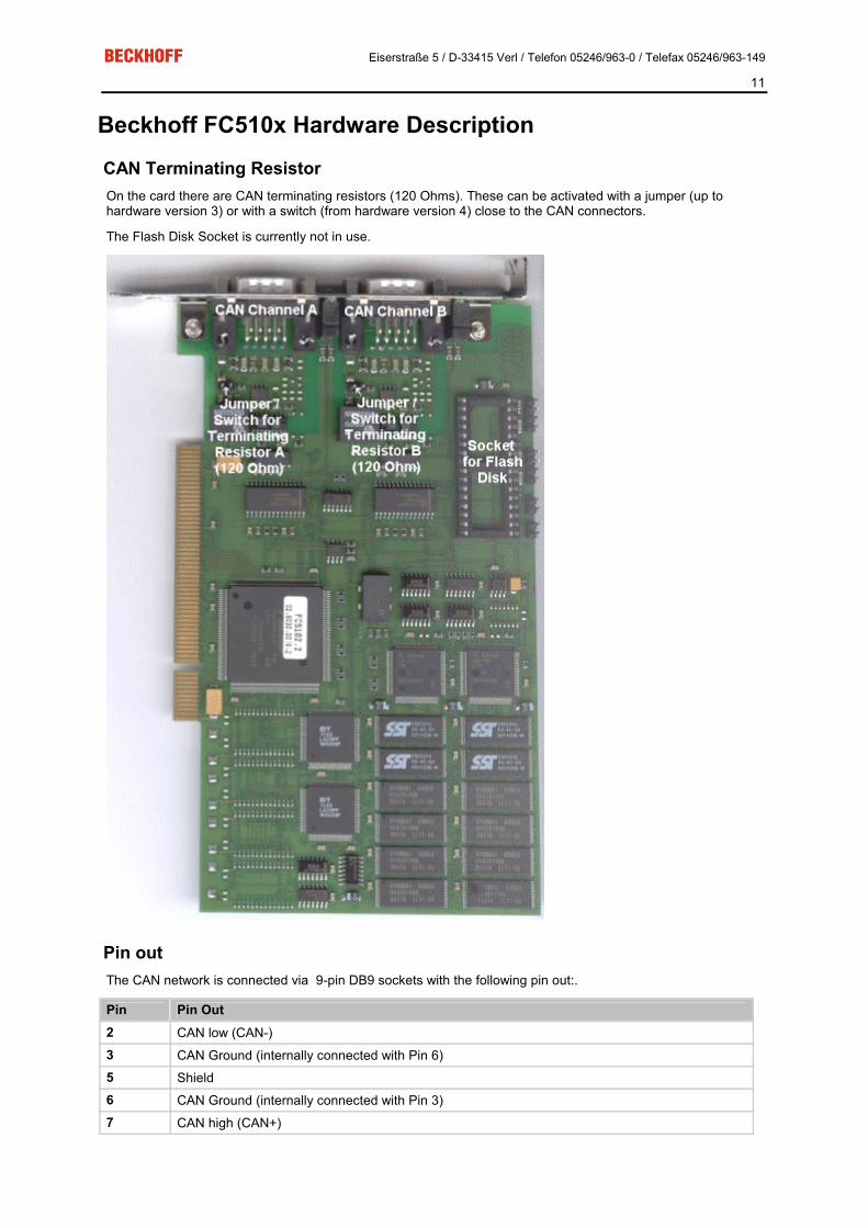
Beckhoff FC510x Hardware Description
CAN Terminating Resistor On the card there are CAN terminating resistors (120 Ohms). These can be activated with a jumper (up to hardware version 3) or with a switch (from hardware version 4) close to the CAN connectors.
The Flash Disk Socket is currently not in use.
Pin out The CAN network is connected via 9-pin DB9 sockets with the following pin out:.
Pin Pin Out 2 CAN low (CAN-) 3 CAN Ground (internally connected with Pin 6) 5 Shield 6 CAN Ground (internally connected with Pin 3) 7 CAN high (CAN+)

Eiserstraße 5 / D-33415 Verl / Telefon 05246/963-0 / Telefax 05246/963-149
12
The pins not mentioned here are not connected.
Note: An auxiliary power up to 30VDC may be connected to Pin 9 (some CAN Devices use this auxiliary power e.g. for transceiver supply).

Eiserstraße 5 / D-33415 Verl / Telefon 05246/963-0 / Telefax 05246/963-149
13
3. Fitting and wiring Installation
Fieldbus PCI cards may only be fitted by qualified personnel in accordance and the following points must be observed.
�� In order to protect the card from electrostatic discharge the user must be discharged before handling the card or the PC.
�� Before opening the PC housing it must be switched off, and the mains plug must be removed.
In may be necessary before fitting to set the jumper in order to activate the internal CAN bus terminating resis-tors, or to set the switch (as from hardware version 3). The jumper being set or the switch being on means that the terminating resistor is connected.
The card can be fitted into any free PCI slot. Ensure that the PCI bus connector is making good contact, and that the module is seated firmly. Fasten the module to the PC slot housing with the fixing screw.
Eiserstraße 5 / D-33415 Verl / Telefon 05246/963-0 / Telefax 05246/963-149
14
Wiring the Bus System Section summary:
CAN topology
Bus length
Drop lines
Star hub
CAN cable
Screening
Cable colours
FC510x: D-sub, 9 pin
BK51x0: 5- pin open style connector
LC5100 bus connection
Fieldbus Box: M 12 CAN socket
Notes related to checking the CAN wiring can be found in the Trouble Shooting section.
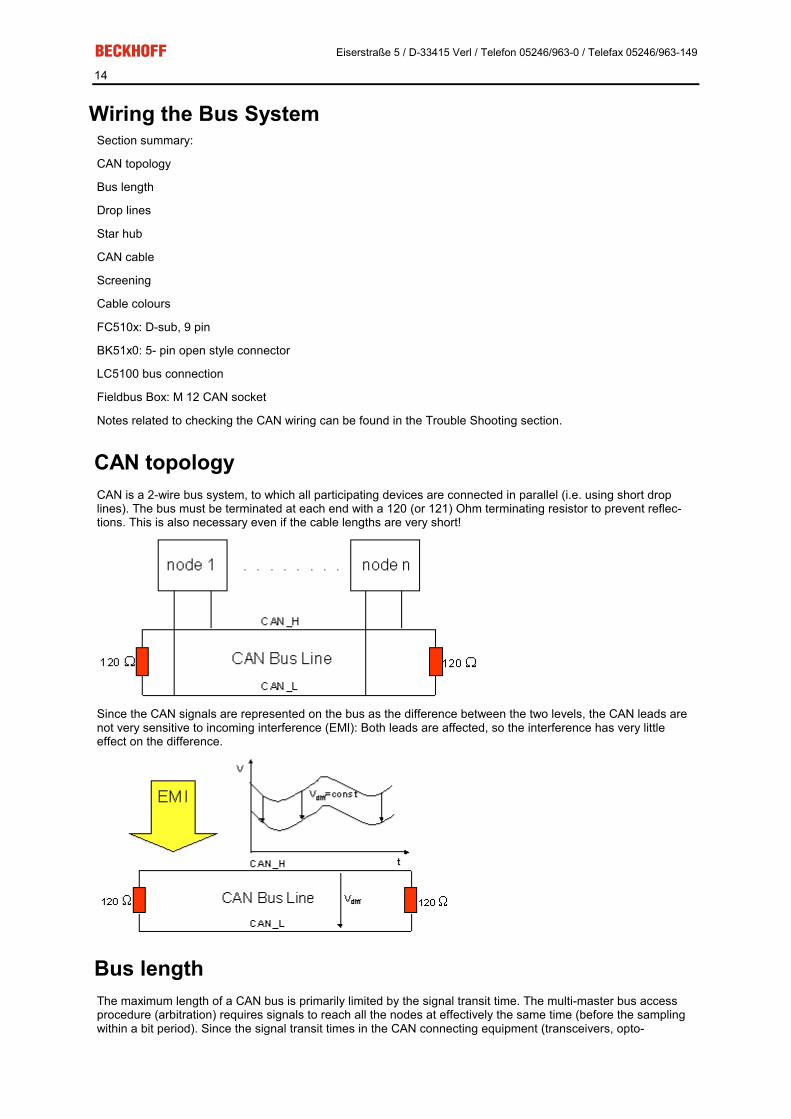
CAN topology CAN is a 2-wire bus system, to which all participating devices are connected in parallel (i.e. using short drop lines). The bus must be terminated at each end with a 120 (or 121) Ohm terminating resistor to prevent reflec-tions. This is also necessary even if the cable lengths are very short!
Since the CAN signals are represented on the bus as the difference between the two levels, the CAN leads are not very sensitive to incoming interference (EMI): Both leads are affected, so the interference has very little effect on the difference.
Bus length The maximum length of a CAN bus is primarily limited by the signal transit time. The multi-master bus access procedure (arbitration) requires signals to reach all the nodes at effectively the same time (before the sampling within a bit period). Since the signal transit times in the CAN connecting equipment (transceivers, opto-

Eiserstraße 5 / D-33415 Verl / Telefon 05246/963-0 / Telefax 05246/963-149
15
couplers, CAN controllers) are almost constant, the line length must be chosen in accordance with the baud rate:
Baud Rate Bus length 1 Mbit/s < 20 m*
500 kbit/s < 100 m
250 kbit/s < 250 m
125 kbit/s < 500 m
50 kbit/s < 1000 m
20 kbit/s < 2500 m
10 kbit/s < 5000 m
*) A figure of 40m at 1 Mbit/s is often found in the CAN literature. This does not, however, apply to networks with optically isolated CAN controllers. The worst case calculation for opto-couplers yields a figure 5 m at 1 Mbit/s - in practice, however, 20 m can be reached without difficulty.
It may be necessary to use repeaters for bus lengths greater than 1000 m.
Drop lines Drop lines must always be avoided as far as possible, since they inevitably cause reflections. The reflections caused by drop lines are not however usually critical, provided they have decayed fully before the sampling time. In the case of the bit timing settings selected in the bus couplers it can be assumed that this is the case, provided the following drop line lengths are not exceeded:
Baud Rate Drop line length Total length of all drop lines 1 Mbit/s < 1m < 5 m
500 kbit/s < 5 m < 25 m
250 kbit/s < 10m < 50 m
125 kbit/s < 20m < 100 m
50 kbit/s < 50m < 250 m Drop lines must not have terminating resistors.
Star Hub (Multiport Tap) Shorter drop line lengths must be maintained when passive distributors ("multiport taps"), such as the Beckhoff ZS5052-4500 Distributor Box. The following table indicates the maximum drop line lengths and the maximum length of the trunk line (without the drop lines):
Baud Rate Drop line length with multiport topology Trunk line length (without drop lines) 1 Mbit/s < 0,3 m < 25 m
500 kbit/s < 1,2 m < 66 m
250 kbit/s < 2,4 m < 120 m
125 kbit/s < 4.8 m < 310 m

Eiserstraße 5 / D-33415 Verl / Telefon 05246/963-0 / Telefax 05246/963-149
16
CAN cable Screened twisted-pair cables (2x2) with a characteristic impedance of between 108 and 132 Ohm is recom-mended for the CAN wiring. If the CAN transceiver’s reference potential (CAN ground) is not to be connected, the second pair of conductors can be omitted. (This is only recommended for networks of small physical size with a common power supply for all the participating devices).
ZB5100 CAN Cable A high quality CAN cable with the following properties is included in Beckhoff's range:
�� 2 x 2 x 0.25 mm² (AWG 24) twisted pairs, cable colours: red/black + white/black
�� double screened
�� braided screen with filler strand (can be attached directly to pin 3 of the 5-pin connection terminal),
�� flexible (minimum bending radius 35 mm when bent once, 70 mm for repeated bending)
�� characteristic impedance (60 kHz): 120 Ohm
�� conductor resistance < 80 Ohm/km
�� sheath: grey PVC, external diameter 7.3 +/- 0.4 mm
�� Weight: 64 kg/km.
�� printed with "BECKHOFF ZB5100 CAN-BUS 2x2x0.25" and metre marking (length data every 20cm)
ZB5200 CAN/DeviceNet Cable The ZB5200 cable material corresponds to the DeviceNet specification, and is also suitable for CANopen sys-tems. The ready-made ZK1052-xxxx-xxxx bus cables for the Fieldbus Box modules are made from this cable material. It has the following specification:
�� 2 x 2 x 0.34 mm² (AWG 22) twisted pairs
�� double screened braided screen with filler strand
�� characteristic impedance (1 MHz): 126 Ohm
�� conductor resistance 54 Ohm/km
�� sheath: grey PVC, external diameter 7.3 mm
�� printed with "InterlinkBT DeviceNet Type 572" as well as UL and CSA ratings
�� stranded wire colours correspond to the DeviceNet specification
�� UL recognised AWM Type 2476 rating
�� CSA AWM I/II A/B 80°C 300V FT1

Eiserstraße 5 / D-33415 Verl / Telefon 05246/963-0 / Telefax 05246/963-149
17
�� corresponds to the DeviceNet "Thin Cable" specification
Screening The screen is to be connected over the entire length of the bus cable, and only galvanically grounded at one point, in order to avoid ground loops. The design of the screening, in which HF interference is diverted through R/C elements to the mounting rail assumes that the rail is appropriately earthed and free from interference. If this is not the case, it is possible that HF interference will be transmitted from the mounting rail to the screen of the bus cable. In that case the screen should not be attached to the couplers - it should nevertheless still be fully connected through.
Notes related to checking the CAN wiring can be found in the Trouble Shooting section.
Cable colours Suggested method of using the Beckhoff CAN cable on Bus Terminal and Fieldbus Box:
BK51x0 pin
Fieldbus Box pin
FC510x pin Function
ZB5100 cable co-lour
ZB5200 cable co-lour
1 3 3 CAN Ground
black/ (red) black
2 5 2 CAN Low black blue
3 1 5 Screen Filler strand Filler strand
4 4 7 CAN high white white
5 2 9 not used (red) (red)
FC510x: D-sub, 9 pin The CAN bus cable is connected to the FC5101 and FC5102 CANopen PCI cards via 9-pin sub-D sockets, with pins assigned as follows.
Pin Assignment 2 CAN low (CAN-) 3 CAN ground (internally connected to pin 6) 5 Screen 6 CAN ground (internally connected to pin 3) 7 CAN high (CAN+) The unlisted pins are not connected.
Note: An auxiliary voltage of up to 30 V DC may be connected to pin 9. Some CAN devices use this to supply the transceiver.

Eiserstraße 5 / D-33415 Verl / Telefon 05246/963-0 / Telefax 05246/963-149
18
BK51x0: 5- pin open style connector The BK51x0 Bus Couplers have a recessed front surface on the left hand side with a five pin connector. The supplied CANopen socket can be inserted here.
The left figure shows the socket in the BK51x0 Bus Coupler. Pin 5 is the connection strip's top most pin. Pin 5 is not used. Pin 4 is the CAN high connection, pin 2 is the CAN low connection, and the screen is connected to pin 3 (which is connected to the mounting rail via an R/C network). CAN-GND can optionally be connected to pin 1. If all the CAN ground pins are connected, this provides a common reference potential for the CAN trans-ceivers in the network. It is recommended that the CAN GND be connected to earth at one location, so that the common CAN reference potential is close to the supply potential. Since the CANopen BK51X0 Bus Couplers provide full electrical isolation of the bus connection, it may in appropriate cases be possible to omit wiring up the CAN ground.
ZS1052-3000 Bus Interface Connector The ZS1052-3000 CAN Interface Connector can be used as an alternative to the supplied connector. This ma-kes the wiring significantly easier. There are separate terminals for incoming and outgoing leads and a large area of the screen is connected via the strain relief. The integrated terminating resistor can be switched exter-nally. When it is switched on, the outgoing bus lead is electrically isolated - this allows rapid wiring fault location and guarantees that no more than two resistors are active in the network.
LC5100: Bus connection via spring-loaded terminals In the low cost LC5100 coupler, the CAN wires are connected directly to the contact points 1 (CAN-H, marked with C+) and 5 (CAN-L, marked with C-). The screen can optionally be connected to contact points 4 or 8, which are connected to the mounting rail via an R/C network.

Eiserstraße 5 / D-33415 Verl / Telefon 05246/963-0 / Telefax 05246/963-149
19
Fieldbus Box: M 12 CAN socket The IPxxxx-B510, IL230x-B510 and IL230x-C510 Fieldbus Boxes are connected to the bus using 5- pin M 12 plug-in connectors.
Beckhoff offer plugs for field assembly, passive distributor's, terminating resistors and a wide range of pre-assembled cables for the Fieldbus Box system. Details be found in the catalog, or under www.beckhoff.de

Eiserstraße 5 / D-33415 Verl / Telefon 05246/963-0 / Telefax 05246/963-149
20
4. Parameterisation and Commissioning TwinCAT System Manager
The TwinCAT System Manager Tool is used to configure the FC510x CANopen PCI card. The System Man-ager provides a representation of the number of programs of the TwinCat PLC systems, the configuration of the axis control and of the connected I/O channels as a structure, and organises the mapping of the data traffic.
For applications without TwinCAT PLC or NC, the TwinCAT System Manager Tool configures the programming interfaces for a wide range of application programs:
�� ActiveX control (ADS-OCX) for e.g. Visual Basic, Visual C++, Delphi, etc.
�� DLL interface (ADS-DLL) for e.g. Visual C++ projects
�� Script interface (ADS script DLL) for e.g. VBScript, JScript, etc.
System Manager – Features - Bit-wise association of server process images and I/O channels
- Standard data formats such as arrays and structures
- User defined data formats
- Continuous variable linking
- Drag and Drop
- Import and export at all levels
Configuration by means of the TwinCAT System Manager The procedure, and the configuration facilities in the System Manager are described below.

Eiserstraße 5 / D-33415 Verl / Telefon 05246/963-0 / Telefax 05246/963-149
21
Context menu
Append Box... <Insert> Adds CANopen slaves (boxes). Currently supports the following boxes (further details on the boxes given later):
Supported boxes Description BK5100 Bus Coupler BK5110 Economy Bus Couplers BK5120 Bus Coupler (successor of BK5100) LC5100 Low-cost Bus Couplers IPxxxx-B510 Fieldbus compact box: CANopen in/output module, protection class IP67 CANopen Node General CANopen device or general CAN device (access via CAN layer 2)
Delete Device... <Del> Removes the FC510x fieldbus card and all subsidiary elements from the I/O configuration.
Online Reset Initiates an online reset on the CANopen bus.

Eiserstraße 5 / D-33415 Verl / Telefon 05246/963-0 / Telefax 05246/963-149
22
"FC510x" tab
PCI Slot/Irq: Shows in which logical PCI slot the card was detected and which IRQ is assigned to it. The IRQ is unused.
Master Node Id: Node address for the FC510x. Value range: 1...127. Determines the identifier of the master heartbeat telegram. Ensure that it is not the same as a slave node address.
Baud rate: Set the Baud rate here. Automatically tests whether the connected slave also supports this baud rate.
Synchronization Mode: The synchronization mode determines the accuracy of the CANopen SYNC telegram generation.
The highest priority task linked with the FC510x device controls the CANopen card and is thereby synchronized with the fieldbus. All other tasks are served asynchronously via corresponding buffers. For all operating modes you can individually set the communication type for each process data object (PDO) - event driven or synchro-nized (in each PDO tab). If one of the PDOs has been configured for synchronous operating mode, a SYNC telegram is sent at the start of the cycle, which the slaves use to synchronize their actions with the master cy-cle.
Depending on the sync accuracy requirements of the application several modes can be selected. Please note, that due to CAN technology a single SYNC telegram may jitter for one entire frame length it the bus is busy at the time of sync generation. The SYNC accuracy therefore refers to the long time stability. Bus nodes that use a phase locked loop (PLL) mechanism to synchronize themselves require a maximum long time stability or accuracy of the SYNC.

Eiserstraße 5 / D-33415 Verl / Telefon 05246/963-0 / Telefax 05246/963-149
23
Slave In slave synchronization mode the card receives its time basis from a sync master. The sync master is selected at the corresponding field.
�� Sync Master: PC-Task. This is the default setting. The PC provides the time basis using the TwinCAT Real Time. Depending on the settings the Task start (Default with TwinCAT NC) or the Task end (De-fault at TwinCAT PLC) triggers the SYNC telegram.
�� Sync Master: Balanced PC Task. This operating mode as well generated the CANopen Sync cycle with the long term accuracy of the PC time basis. However, the short term accuracy (interval between two SYNC telegrams) is better that with Sync Master "PC-Task": - Run time differences (e.g. caused by case dependent program calls) are leveled out, - the FC510x delays pending transmit telegrams until the SYNC telegram was sent, - the SYNC intervals are determined by the quartz timer of the FC510x card. The card timer is adjusted in small steps to the PC-timer if the difference is larger that the value of the "PLL Sync Time". In this mode the SYNC telegram is delayed for the Shift Time after the end of the TwinCAT task cycle. Here the shift time should be set to a value as small as possible - but large enough to allow the proc-ess data access by the TwinCAT task. The function "Calculate Equi-Times" helps to configure the op-timal shift time. It is started by selecting the corresponding button.

Eiserstraße 5 / D-33415 Verl / Telefon 05246/963-0 / Telefax 05246/963-149
24
Master In master synchronization mode the card generates its time basis locally. The SYNC is generated with long time quartz accuracy. The start of the TwinCAT task is triggered by the card, delayed by the Shift Time. In this mode the shift time value should be as large as possible. The function "Calculate Equi-Times" helps to config-ure the optimal shift time. It is started by selecting the corresponding button.
Cycle Time: Displays the cycle time of the corresponding highest priority task. The value is updated when the TwinCAT mapping is generated.
Sync-Cycle Multiplier: CANopen SYNC Cycle Time = (Task) Cycle Time x Sync-Cycle Multiplier. Event driven PDO communications and cyclic synchronized PDO communication are frequently combined when used in conjunction with CANo-pen. In order to be able to respond rapidly to an event, the TwinCAT task cycle time has to be less than the CANopen SYNC cycle time.
Sync-Cycle time Shows the cycle time of the CANopen SYNC telegram. This cycle time is derived from the highest priority task which has process data linked to the card, and the Sync Cycle Multiplier.
Sync-Tx-PDO Delay: Directly after the SYNC telegram, the synchronized slaves send their input data/actual values. The FC510x can delay the sending of the output data / set value (TxPDOs from the perspective of the card) in order to minimize the telegram burst directly after the SYNC. The Sync-Tx-PDO delay parameter is used to set this delay in per-cent of the Sync Cycle Time.
Example:

Eiserstraße 5 / D-33415 Verl / Telefon 05246/963-0 / Telefax 05246/963-149
25
Task Cycle Time = 2000µs, Sync Cycle Multiplier = 5, Sync Tx-PDO Delay =40[%]. Event driven PDOs can be processed by the PLC task every 2 ms. The CANopen sync cycle is 10 ms, the FC510x sends its synchronized PDOs 4ms (=40% of 10ms) after SYNC.
Search...: Searches for all connected FC510x channels. Select those required. In the case of an FC5102 both channels A and B appear. These behave in logical terms like two FC5101 cards.
Hardware Configuration …: In which the address of the FC510x is set in the lower memory area (below 1 MB) of the PC.
Upload Configuration: Scans the CANopen network and adds all detected equipment to the device (FC510x) (only available when no box has been configured). In the case of Beckhoff boxes, reads the configuration precisely. In the case of ex-ternal devices, the PDO configuration and the identity object are read and evaluated.
Verify Configuration: Allows one to compare the expected (configured) network configuration with the actual (physically present) configuration. The data from the CANopen Identity object is read an compared. In the case of Beckhoff Boxes the connected Bus Terminals or Extension Modules are identified ad compared. In preparation.
Firmware: Shows the current firmware version of the FC510x.
Firmware Update...: Update the FC510x card firmware version here. Warning: The TwinCAT System must be stopped for this func-tion.
”ADS” tab The FC510x is an ADS device with its own net ID, which can be changed here. All ADS services (diagnosis, non-cyclical communication) going to the FC510x must address this net ID.
Eiserstraße 5 / D-33415 Verl / Telefon 05246/963-0 / Telefax 05246/963-149
26
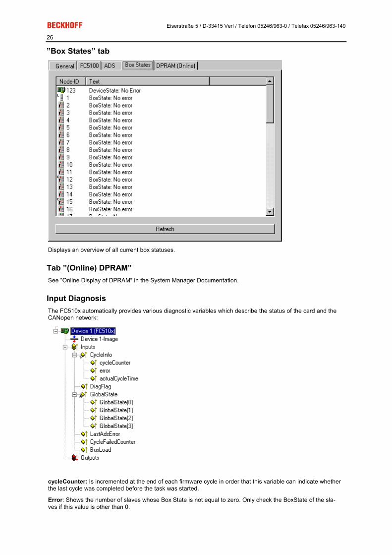
”Box States” tab
Displays an overview of all current box statuses.
Tab ”(Online) DPRAM” See ”Online Display of DPRAM" in the System Manager Documentation.
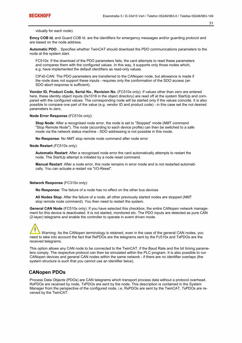
Input Diagnosis The FC510x automatically provides various diagnostic variables which describe the status of the card and the CANopen network:
cycleCounter: Is incremented at the end of each firmware cycle in order that this variable can indicate whether the last cycle was completed before the task was started.
Error: Shows the number of slaves whose Box State is not equal to zero. Only check the BoxState of the sla-ves if this value is other than 0.

Eiserstraße 5 / D-33415 Verl / Telefon 05246/963-0 / Telefax 05246/963-149
27
ActualCycleTime: Shows the current cycle time in 4/25 µs. This variable is only updated when all slaves are involved in the data exchange (and when error is 0)
DiagFlag: Shows whether the diagnostics information on the card has changed. This can be read off using ADS Read. For that purpose, specify the net ID of the FC510x, the port number 200 and the IndexGroup 0xF100. The IndexOffset and the length then relate to the diagnostic data. (Note: The Box States are also avai-lable as box variables.)
Offset 1-127: BusStatus List, 1-127 one byte per station address which contains the station status (see Box-State for CANopenboxes)
Global State: Various diagnostic and status displays for the FC510x. The byte in GlobalState(0) shows the status of the card in relation to the TwinCAT system: RUN, RESET, OFFLINE and STOP are distinguished. GlobalState(2) gives information about the status of the CAN controller: "CAN Warning Limit Reached" and "Bus Off" are displayed. Warning limit reached means that the send/receive error counter on the CAN controller has exceeded the value 96. BusOff means that the CAN controller can no longer participate in bus communica-tion; this is caused by an excessive number of CAN errors (Error Frames). In this case there is a serious physi-cal error in the CAN network. (e.g. too little or too much matching resistors, at least a device with an incorrect baudrate, short circuit etc.) The bus off state is only left by a card reset. Details about further global state data, see comments in ”Online” tab.
LastAdsError: Shows the error code of the last ADS access error, e.g. if an attempt has been made to read the diagnostic data for a deactivated node.
CycleFailedCounter: Counts the number of firmware cycles which could not be completed before the associ-ated task wanted to re-read/re-write the process image. If this counter is incremented, the task cycle time has been set too low for the actual network configuration.
BusLoad: Shows the current bus load in %. The Bus Load is an important design criterion for CAN networks. The value shown is a average value over 100ms.

Eiserstraße 5 / D-33415 Verl / Telefon 05246/963-0 / Telefax 05246/963-149
28
BK51x0/LC5100/IPxxxx-B510 (CANopen) The BK51x0 Bus Coupler and the IPxxx-B510 fieldbus box are installed in the CANopen bus. Those specific properties which distinguish them from other Bus Couplers and/or Fieldbus Box modules are described below. Following Bus Couplers are currently supported by TwinCAT:
Types Description BK5100 Bus Coupler BK5110 Economy Buskoppler BK5120 Bus Coupler, successor of BK5100 LC5100 Low-cost Bus Coupler IPxxxx-B510 Fieldbus Compact Box: CANopen in/output module, protection class IP67 ILxxxx-B510 Fieldbus Coupler Box: Expandable CANopen in/output module, protection class IP67
"BK51x0/IX-B510" tab
Node Id: Sets the node ID of the CAN bus device (between 1 and 63 (BK51x0) and/or 1 and 99 (IPxxxx-B510)). This value must comply with the value set at the Bus Coupler and/or at the compact box.
Guard time: Cycle time for the node monitoring (node guarding).
Life time factor: Guard time multiplied produces the watchdog time for the monitoring of the master by the coupler (life guarding). Life guarding is deactivated if the lifetime factor is set to zero.
Inhibit time: Displays the minimum send interval for PDOs (telegrams) with analogue and special signals. If more than digital 64 signals are present, these are also provided with this Inhibit Time.
Event Time: Sets the Event Timer Value for Transmit PDOs. The expiration of this timer is regarded as addi-tional event for the corresponding PDO. Thus the PDO is being sent. If the application event occurs during the event timer period the PDO is sent as well and the timer is reset.
K-Bus Update: Calculates the anticipated duration of a complete update of the terminal bus (according to type and number of connected terminals).
Trans.Type: Gives the Transmission Type for digital / analogue input telegrams. 254 + 255 corresponds to the event-driven transfer, 1 … 240 are synchronous transfer types. For further details see also BK51X0 manual.

Eiserstraße 5 / D-33415 Verl / Telefon 05246/963-0 / Telefax 05246/963-149
29
Firmware Update: Enables the updating of the coupler firmware via the serial interface (requires KS2000 soft-ware package interface cable).
”SDOs” tab
SDO inputs sent to the node at StartUp are displayed/managed on this page. Inputs with an object index in straight brackets are automatically created on the basis of the updated terminal configuration. Other inputs can be managed using ”Add”, ”Insert”, ”Delete” and ”Edit”.
”ADS” tab In order to be able to read and write SDO objects during the running time (e.g. from the PLC), the node (Bus Coupler) can be allocated an ADS port (CIFx0-CAN). The FC510x provides an ADS port at all times for every node since the diagnostic information is transported via ADS. These ports can be used to read and write SDO objects using ADS read requests and/or write requests.
The ADS IndexGroup contains the CANopen object index and the ADS IndexOffset contains the CANopen SubIndex. For details see Chapter SDO Communication
"Diag" tab The diag tab displays the diagnosics information. The window contents are not refreshed cyclically. If required dial the "Refresh" button. The represented diagnosis information can be also questioned by ADS.

Eiserstraße 5 / D-33415 Verl / Telefon 05246/963-0 / Telefax 05246/963-149
30
CANopen Device CANopen devices which are not recognised by the TwinCAT System Manager can be incorporated into the network by selecting the box ”CANopen Node”. The CAN(open) messages (PDOs) can be configured directly for these devices. This will guarantee the optimum flexibility of this general CANopen interface.
When using the FC510x, this box also enables you to receive and send any CAN identifier - this enables com-munication with any CAN node. The only condition is the support of at least one of the Baud Rates supported by the FC510x.
"CAN Node" tab
Node ID: Enter the general CANopen device node address here. If you select the ”Auto Adapt PDO COB Ids” box, the default identifier for the process data object can also be carried out after changing the node ID.
Profile No.: After CANopen, the parameter 0x1000 "Device Type" contains the number of the supported device profile in both the lowest value bytes. These are entered here and compared at the system StartUp with the device parameters present. If no device profile is supported, the parameter will contain the value 0.
Add Info: The additional info is located in both the highest value bytes of the object directory entry 0x1000 (de-vice type).
FC510x: Comparison of the set/actual configuration takes place only if the profile no. or add info (i.e. object directory entry 0x1000) are configured to a value other than zero. If the expected data at the system start do not comply with the values present, the StartUp of this node will be inter-rupted and a corresponding error message will appear in the Diag Tab.
CIFx0-CAN: The values are continuously compared (even if ”0” is entered in both). If values do not comply, the node StartUp is interrupted.
Guard Time: The guard time determines the interval in which the node is monitored (node guarding). 0 signifies no monitoring.
Life time factor: Guard time x lifetime factor determines the watchdog length for the mutual monitoring of card and CANopen nodes. 0 indicates that the CANopen node is not monitoring the card. At 0 the card takes the guard time directly as the watchdog length.
FC510x: This card also supports the heartbeat protocol and firstly attempts to start this form of node monitoring on the CANopen node (write access to objects 0x1016 and 0x1017 in the object directory). If this attempt fails, guarding is activated. The guard time as producer heartbeat time and (guard time x lifetime factor) as consumer heartbeat time are entered. The card then transmits its heartbeat telegram with the smallest configured guard time (the guard times can be set indi-
Eiserstraße 5 / D-33415 Verl / Telefon 05246/963-0 / Telefax 05246/963-149
31
vidually for each node).
Emcy COB Id. and Guard COB Id. are the identifiers for emergency messages and/or guarding protocol and are based on the node address.
Automatic PDO... Specifies whether TwinCAT should download the PDO communications parameters to the node at the system start.
FC510x: If the download of the PDO parameters fails, the card attempts to read these parameters and compares them with the configured values. In this way, it supports only those nodes which, e.g. have implemented the default identifiers as read-only values.
CIFx0-CAN: The PDO parameters are transferred to the CANopen node, but allowance is made if the node does not support these inputs - requires only the conformation of the SDO access (an SDO abort response is sufficient).
Vendor ID, Product Code, Serial No., Revision No. (FC510x only): If values other than zero are entered here, these identity object inputs (0x1018 in the object directory) are read off at the system StartUp and com-pared with the configured values. The corresponding node will be started only if the values coincide. It is also possible to compare one part of the value (e.g. vendor ID and product code) - in this case set the not desired parameters to zero.
Node Error Response (FC510x only):
Stop Node: After a recognised node error, the node is set to ”Stopped” mode (NMT command "Stop Remote Node"). The node (according to each device profile) can then be switched to a safe mode via the network status machine - SDO addressing is not possible in this mode.
No Response: No NMT stop remote node command after node error
Node Restart (FC510x only):
Automatic Restart: After a recognised node error the card automatically attempts to restart the node. The StartUp attempt is initiated by a node reset command.
Manual Restart: After a node error, this node remains in error mode and is not restarted automati-cally. You can actuate a restart via "I/O-Reset".
Network Response (FC310x only):
No Response: The failure of a node has no effect on the other bus devices
All Nodes Stop: After the failure of a node, all other previously started nodes are stopped (NMT stop remote node command). You then need to restart the system.
General CAN Node (FC510x only): If you have selected this checkbox, the entire CANopen network manage-ment for this device is deactivated. It is not started, monitored etc. The PDO inputs are detected as pure CAN (2-layer) telegrams and enable the controller to operate in event driven mode.
Warning: As the CANopen terminology is retained, even in the case of the general CAN nodes, you need to take into account the fact that RxPDOs are the telegrams sent by the Fc510x and TxPDOs are the received telegrams.
This option allows any CAN node to be connected to the TwinCAT, if the Baud Rate and the bit timing parame-ters comply. The respective protocol can then be simulated within the PLC program. It is also possible to run CANopen devices and general CAN nodes within the same network - if there are no identifier overlaps (the system structure is such that you cannot use an identifier twice).
CANopen PDOs Process Data Objects (PDOs) are CAN telegrams which transport process data without a protocol overhead. RxPDOs are received by node, TxPDOs are sent by the node. This description is contained in the System Manager from the perspective of the configured node, i.e. RxPDOs are sent by the TwinCAT, TxPDOs are re-ceived by the TwinCAT.

Eiserstraße 5 / D-33415 Verl / Telefon 05246/963-0 / Telefax 05246/963-149
32
”PDO” tab
COB Id: The CAN identifier of this PDO. For every two send and receive PDOs per node, CANopen provides Default Identifiers. These can then be changed.
Trans.Type: The Transmission Type determines the send behaviour of the PDO. 255 corresponds to the event driven send.
Inhibit time: Send Delay between two identical PDOs. Is entered in multiples of 0.1 ms.
Length: The length of the PDO is based on the mapped variables and cannot therefore be edit here.
Event Time (FC510x only): Enter the value for the Event Timer in ms. For send PDOs (here: RxPDOs, see above) the StartUp of this timer triggers an additional PDO send, for receive PDOs (here: TxPDOs) the arrival of a PDO within the pre-set value is monitored and the box state of the node is changed as appropriate. If 0, the parameter is not transferred to the node.
TwinCAT creates corresponding inputs in the node object directory on the basis of the parameters entered here. These are transferred via SDO at the system start. You can view the inputs at the SDO tab. If this behav-iour is not required, you can deactivate "Auto Download of PDO Parameters" by selecting the checkbox at the CAN node tab.
Tree Representation:
TwinCAT firstly provides two send and receive PDOs, with Default Identifiers, for a general CANopen node. Superfluous PDOs can be selected and removed.
TxPDOs are sent by the CANopen node and generally contain inputs. RxPDOs are received by the node, i.e., sent by TwinCAT.
Add variables to the PDOs by right clicking on ”Inputs” and/or ”Outputs” and selecting the corresponding vari-able(s). If several variables of the same type are inserted with a single action, the offset within the PDO will be created automatically. If variables are inserted one after another, you need to set the corresponding offset (start address within the CAN telegram) for each variable.
Warning: Please note that TwinCAT assigns the PDOs to the object dictionary entries in the node using

Eiserstraße 5 / D-33415 Verl / Telefon 05246/963-0 / Telefax 05246/963-149
33
the sequence in which the system manager displays the PDOs. For instance the PDO communication parame-ter of the third listed TxPDO are always written to index 0x1802 - independent of the name of the PDO in the system manager. So if only PDO1 and PDO3 are to be used, PDO2 has to be entered as well - in this case without variables assigned. PDOs without variables are not sent and are not expected by the card.
Context menu:
The menu alongside is obtained by right clicking on the general CANopen node. Here you can insert further Tx PDOs and/or Rx PDOs.
”SDOs” tab
SDO inputs sent to the node at StartUp are displayed/managed on this page. Inputs with an object index in straight brackets are automatically created on the basis of the updated terminal configuration. Other inputs can be managed using ”Add”, ”Insert”, ”Delete” and ”Edit”.
”ADS” tab In order to be able to read and write SDO objects during the running time (e.g. from the PLC), the node (Bus Coupler) can be allocated an ADS port (CIFx0-CAN). The FC510x provides an ADS port at all times for every node since the diagnostic information is transported via ADS. These ports can be used to read and write SDO objects using ADS read requests and/or write requests.
The ADS IndexGroup contains the CANopen object index and the ADS IndexOffset contains the CANopen SubIndex.

Eiserstraße 5 / D-33415 Verl / Telefon 05246/963-0 / Telefax 05246/963-149
34
CANopen eds Files The configuration options for a CANopen device are available in eds files (electronic data sheets) in a standard data format. The data format is specified in CiA DSP 306. A tool is available from the CAN-in-Automation e.V. user association with which this data format can be checked.
Since it was found that a large number of eds files do not properly observe the standard, Beckhoff have until now not supported eds files in the system manager. The direct configuration of PDO parameters makes it pos-sible to adapt to the devices that are to be incorporated, and also to use devices that do not entirely meet the standard.

Eiserstraße 5 / D-33415 Verl / Telefon 05246/963-0 / Telefax 05246/963-149
35
5. CANopen Communication NMT Simple Boot-Up CANopen allows the distributed network to boot in a very simple way. After initialisation, the modules are auto-matically in the Pre-Operational state. In this state it is already possible to access the object directory using service data objects (SDOs) with default identifiers, so that the modules can be configured. Since default set-tings exist for all the entries in the object directory, it is in most cases possible to omit any explicit configuration.
Only one CAN message is then required to start the module: Start_Remote_Node: Identifier 0, two data bytes: 0x01, 0x00. It switches the node into the Operational state.
Network Status The states and the state transitions involved as CANopen boots up can be seen from the state diagram:
Pre-Operational After initialisation the bus coupler goes automatically (i.e. without the need for any external command) into the Pre-Operational state. In this state it can be configured, since the service data objects (SDOs) are already ac-tive. The process data objects, on the other hand, are still locked.
Operational In the Operational state the process data objects are also active.
If external influences (such as a CAN error, or absence of output voltage) or internal influences (such as a K-Bus error) mean that it is no longer possible for the bus coupler to set outputs, to read inputs or to communi-cate, it attempts to send an appropriate emergency message, goes into the fault state, and thus returns to the Pre-Operational state. In this way the NMT status machine in the network master can also immediately detect fatal errors.
Stopped In the Stopped state (formerly: Prepared) data communication with the coupler is no longer possible - only NMT messages are received. The outputs go into the fault state.
Eiserstraße 5 / D-33415 Verl / Telefon 05246/963-0 / Telefax 05246/963-149
36
State Transitions The network management messages have a very simple structure: CAN identifier 0, with two bytes of data con-tent. The first data byte contains what is known as the command specifier (cs), and the second data byte con-tains the node address, the node address 0 applying to all nodes (broadcast).
11 bit identifier 2 byte of user data
0x00 cs Node-ID
The following table gives an overview of all the CANopen state transitions and the associated commands (command specifier in the NMT master telegram):
Status transition
Command Specifier cs Explanation
(1) - The initialisation state is reached automatically at power-up
(2) - After initialisation the pre-operational state is reached automatically - this involves sending the boot-up message.
(3), (6) cs = 1 = 0x01 Start_Remote_Node. Starts the module, enables outputs, starts transmission of PDOs.
(4), (7) cs = 128 = 0x80 Enter_Pre-Operational. Stops PDO transmission, SDO still active.
(5), (8) cs = 2 = 0x02 Stop_Remote_Node. Outputs go into the fault state, SDO and PDO switched off.
(9), (10), (11)
cs = 129 = 0x81 Reset_Node. Carries out a reset. All objects are reset to their power-on defaults.
(12), (13), (14)
cs = 130 = 0x82 Reset_Communication. Carries out a reset of the communication functions. Objects 0x1000 - 0x1FFF are reset to their power-on defaults.
Example 1 The following telegram puts all the modules in the network into the error state (outputs in a safe state):
11 bit identifier 2 byte of user data
0x00 0x02 0x00
Example 2 The following telegram resets node 17:
11 bit identifier 2 byte of user data
0x00 0x81 0x11
Boot-up message After the initialisation phase and the self test, the bus coupler sends the boot-up message, a CAN message with one data byte (0) and the identifier of the guarding or heartbeat message: CAN-ID = 0x700 + Node-ID. In this way temporary failure of a module during operation (e.g. due to a voltage interruption), or a module that is switched on at a later stage, can be reliably detected, even without Node Guarding. The sender can be deter-mined from the message identifier (see default identifier distribution).
It is also possible, with the aid of the boot-up message, to recognise the nodes present in the network at start-up with a simple CAN monitor, without having to make write access to the bus (such as a scan of the network by reading out parameter 0x1000).
Finally, the boot-up message communicates the end of the initialisation phase; the bus coupler signals that it can now be configured or started.
Note
Up to firmware status BA the emergency identifier was used for the boot up message.
Eiserstraße 5 / D-33415 Verl / Telefon 05246/963-0 / Telefax 05246/963-149
37
Format of the Boot-up message 11 bit identifier 1 byte of user data
0x700(=1792)+ node ID 0x00
Node Monitoring Heartbeat and guarding mechanisms are available to monitor failures in the CANopen network. These are of particular importance for CANopen, since modules do not regularly speak in the event-driven mode of opera-tion. In the case of "guarding", the devices are cyclically interrogated about their status by means of a data re-quest telegram (remote frame), whereas with "heartbeat" the nodes transmit their status on their own initiative.
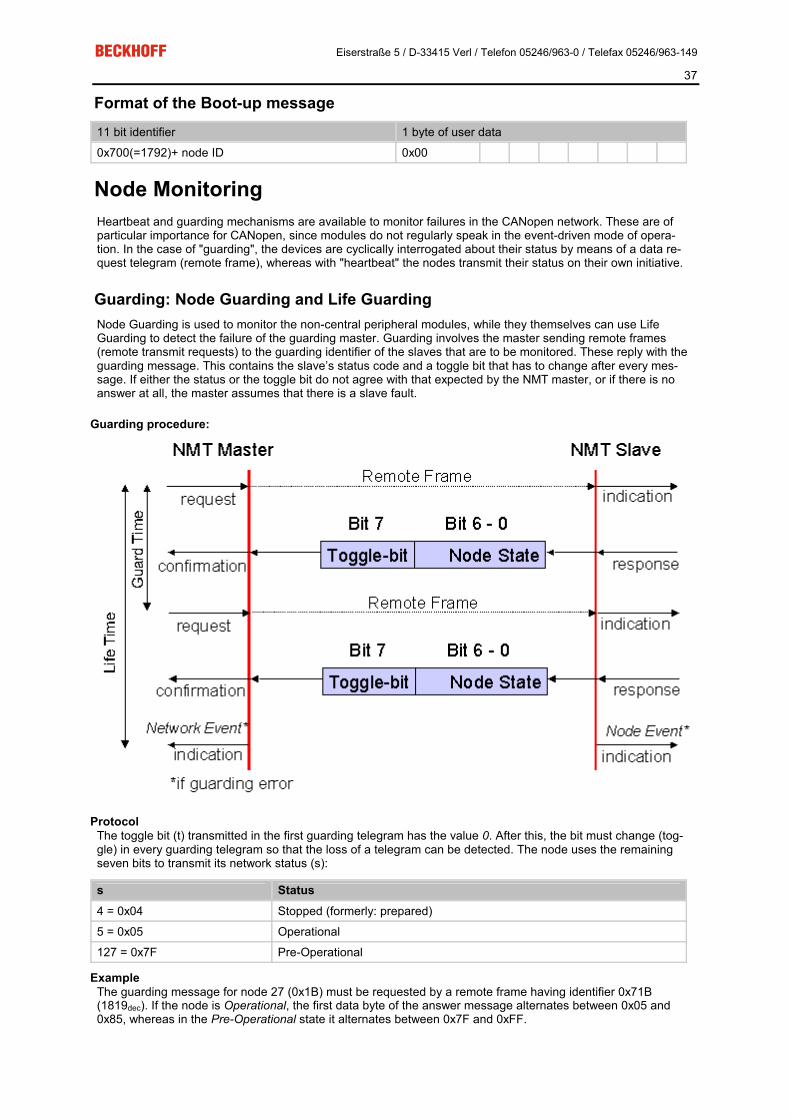
Guarding: Node Guarding and Life Guarding Node Guarding is used to monitor the non-central peripheral modules, while they themselves can use Life Guarding to detect the failure of the guarding master. Guarding involves the master sending remote frames (remote transmit requests) to the guarding identifier of the slaves that are to be monitored. These reply with the guarding message. This contains the slave’s status code and a toggle bit that has to change after every mes-sage. If either the status or the toggle bit do not agree with that expected by the NMT master, or if there is no answer at all, the master assumes that there is a slave fault.
Guarding procedure:
Protocol The toggle bit (t) transmitted in the first guarding telegram has the value 0. After this, the bit must change (tog-gle) in every guarding telegram so that the loss of a telegram can be detected. The node uses the remaining seven bits to transmit its network status (s):
s Status 4 = 0x04 Stopped (formerly: prepared)
5 = 0x05 Operational
127 = 0x7F Pre-Operational
Example The guarding message for node 27 (0x1B) must be requested by a remote frame having identifier 0x71B (1819dec). If the node is Operational, the first data byte of the answer message alternates between 0x05 and 0x85, whereas in the Pre-Operational state it alternates between 0x7F and 0xFF.

Eiserstraße 5 / D-33415 Verl / Telefon 05246/963-0 / Telefax 05246/963-149
38
Guard time and life time factor If the master requests the guard messages in a strict cycle, the slave can detect the failure of the master. In this case, if the slave fails to receive a message request from the master within the set Node Life Time (a guarding error), it assumes that the master has failed (the watchdog function). It then puts its outputs into the error state, sends an emergency telegram, and returns to the pre-operational state. After a guarding time-out the procedure can be re-started by transmitting a guarding telegram again.
The node life time is calculated from the guard time (object 0x100C) and life time factor (object 0x100D) pa-rameters:
Life time = guard time x life time factor
If either of these two parameters is ”0” (the default setting), the master will not be monitored (no life guarding).
Heartbeat: Node Monitoring without Remote Frame In the heart beat procedure, each node transmits its status message cyclically on its own initiative. There is therefore no need to use remote frames, and the bus is less heavily loaded than under the guarding procedure.
The master also regularly transmits its heartbeat telegram, so that the slaves are also able to detect failure of the master.
Heartbeat procedure
Protocol The toggle bit is not used in the heart beat procedure. The nodes send their status cyclically (s). See Guarding.
Eiserstraße 5 / D-33415 Verl / Telefon 05246/963-0 / Telefax 05246/963-149
39
Start-up Behaviour of the FC510x CANopen PCI Card
Introduction The firmware in the FC510x CANopen PCI card treats each individual node separately. The first action follow-ing the system start is to check for the presence of the expected nodes, and whether they basically correspond to the devices that have been configured. Following this, each node is parameterised and started, independ-ently of the others. The starting behaviour of a node is described below.
1. Reset All Nodes The starting sequence begins with the global Reset Communication telegram, so that all nodes are brought in to a defined initial state.
2. Identify Node Presence of the nodes is first established through an SDO upload of the object 0x1000 (device type). The con-tent supplied by a node is checked for agreement with the expected value. Object 0x1000 is composed of the profile number and of the additional information - both values can be found on the CAN Node tab.
If both the additional information and the profile number are set to "0", the contents returned for object 0x1000 is not checked. An answer containing an SDO abort protocol cannot be tolerated; the process is interrupted.
For values other than zero, the next step is only taken if the value is as expected. Otherwise the process is aborted and the node enters state 0x04 (SDO syntax error at start-up if an SDO abort message has been re-ceived or if the data length is incorrect) or state 0x05 (if there is an SDO data mismatch at start-up or the value do not comply) and an appropriate error message is displayed in the dialog box.
If the node does not answer the SDO upload telegram, then the SDO protocol is interrupted after it has timed out (approx. 2 seconds) and then repeated after a waiting time (of approx. 1 second) until the node answers. In this phase, the node is in state 0x02 (node not found).
If the vendor ID, the product code, the serial no. or the revision no. have been configured to values other than zero on the CAN Node's tab, then the corresponding values are read and compared in the node's object 0x1018. The booting process is only continued if they are as expected.
3. Set SYNC Time If synchronous PDOs have been configured, an attempt is now made a to enter the given Sync Cycle Time into object 0x1006 (SYNC interval). Because this object is optional, the boot up is still continued even if the node acknowledges negatively - it is, however, necessary for the node to answer.
4. Set PDO Parameters If the "Auto-download PDO parameters" checkbox on the CAN node's tab has been selected (which it is by default) then the PDO parameters for all the configured PDOs are now written. These are the identifier and the transmission type. The Inhibit Time and the Event Time are only written at this stage if they have been config-ured to have values other than zero.
If a node answers an SDO download of the PDO parameters with an SDO abort protocol, then the correspond-ing entry is then read (SDO upload) and compared with the value to be written. If they are in agreement, the process continues. In this way it is possible for read-only PDO parameters to be tolerated, provided they agree with the configured values.
The next step is only taken if the download, or the comparison with existing values, is successful. Otherwise the process is aborted, and the node enters state 0x04 or 0x05, and the appropriate error message is displayed in the dialog box.
5. Set Guarding/Heartbeat If a value other than zero has been configured for the Guard Time, the appropriate parameters are now written to the nodes. Because the heartbeat process generates less bus loading than guarding, an attempt is first ma-de to start this form of node monitoring on the CANopen nodes.
Heartbeat: The guard time is entered as the producer heartbeat time (0x1017) and the product of (guard time x life time factor) is entered as the consumer heartbeat time (0x1016). The FC510x card then transmits cyclically

Eiserstraße 5 / D-33415 Verl / Telefon 05246/963-0 / Telefax 05246/963-149
40
its heartbeat telegram with the smallest configured guard time (the guard times can be set individually for each node). If the node refuses the entry of the consumer heartbeat time, then it is assumed that the node does not support monitoring of the master - this is tolerated. If entry of the producer heartbeat time also fails, then the guarding protocol is configured.
Guarding: If the node does not support the heartbeat, then the guarding parameters (guard time, 0x100C and life time factor, 0x100D) are entered.
If this attempt also fails, then the start-up process is aborted, and the node enters state 0x04, with an appropri-ate error message being sent to the dialog box.
6. Download User Parameters The objects added manually on the SDO tab are now transmitted to the node by SDO download. Once again, if the SDO is interrupted the value is fed back and checked for agreement, so that read-only parameters can be tolerated. The process only continues it successful, and otherwise is aborted.
7. Start Node After all the parameters have successfully been downloaded, the node is switched into the operational state by means of an individual Start_Remote_Node telegram. RxPDOs are first sent to the nodes about 1 s after this start telegram, and the guarding or heartbeat protocol begins. Node monitoring by heartbeat does not start until the node's producer heartbeat telegram has been received for the first time.
Because CANopen does not provide explicit confirmation of the start process, it is only possible to evaluate the first arrival of the transmit PDOs. Until all the configured TxPDOs have arrived, the state of the node remains set to 0x17 (expected TxPDO is missing).
After all configured nodes have been found, successfully parameterised and individually started, the FC510x card again sends a global Start_Remote_Node telegram (with node ID=0).
8. SYNC SYNC telegrams are first sent after the linked task with the highest priority has been started. Synchronous TxPDOs are also therefore triggered until this task is running - this can also be a reason for the node state re-maining at 0x17.
Example of a boot up sequence: Node with node ID1, identifier in hex code.
Time ID DLC DATA description
0.1244 00 2 82 00 Reset communication all nodes All nodes are set to their initial state 0.1252 601 8 40 00 10 00 00 00 00 00 [1000,00] Initiate Upload Rq. First attempt to find node 1 - node is still reset 2.1316 601 8 80 00 00 00 00 00 04 05 05040000 [0000,00] Abort: SDO protocol timed out Node has not responded within the SDO timeout period (2 sec), SDO is aborted 2.7875 701 1 00 Boot-up Node has carried out its reset process, and announces itself with boot up message 4.1391 601 8 40 00 10 00 00 00 00 00 [1000,00] Initiate Upload Rq. Second attempt to find node 1. Read access to object 0x1000 4.1411 581 8 43 00 10 00 91 01 07 00 91 01 07 00 [1000,00] Initiate Upload Rsp. expedited Node 1 answers with profile no. 0x191 (401 dec) and additional info 0x07 4.1418 601 8 40 18 10 01 00 00 00 00 [1018,01] Initiate Upload Rq. The Vendor ID is read 4.1434 581 8 43 18 10 01 02 00 00 00 02 00 00 00 [1018,01] Initiate Upload Rsp. expedited Node 1 with vendor ID 0x02 (= Beckhoff) 4.1442 601 8 23 00 18 01 81 01 00 00 81 01 00 00 [1800,01] Initiate Download Rq. expedited The identifier for TxPDO1 is now written: 0x181 4.1831 581 8 60 00 18 01 00 00 00 00 [1800,01] Initiate Download Rsp Node 1 confirms the download 4.1840 601 8 23 01 18 01 81 02 00 00 81 02 00 00 [1801,01] Initiate Download Rq. expedited

Eiserstraße 5 / D-33415 Verl / Telefon 05246/963-0 / Telefax 05246/963-149
41
Identifier for TxPDO2 is 0x281 4.2223 581 8 60 01 18 01 00 00 00 00 [1801,01] Initiate Download Rsp 4.2230 601 8 23 00 14 01 01 02 00 00 01 02 00 00 [1400,01] Initiate Download Rq. expedited Identifier for RxPDO1 is 0x201 4.2347 581 8 60 00 14 01 00 00 00 00 [1400,01] Initiate Download Rsp 4.2356 601 8 2f 00 18 02 ff 00 00 00 ff [1800,02] Initiate Download Rq. expe-dited Transmission Type for TxPRO1 is 0xFF=255 4.2737 581 8 60 00 18 02 00 00 00 00 [1800,02] Initiate Download Rsp 4.2744 601 8 2f 01 18 02 ff 00 00 00 ff [1801,02] Initiate Download Rq. expe-dited Transmission Type for TxPRO2 is 0xFF=255 4.3133 581 8 60 01 18 02 00 00 00 00 [1801,02] Initiate Download Rsp 4.3141 601 8 2f 00 14 02 ff 00 00 00 ff [1400,02] Initiate Download Rq. expe-dited Transmission Type for RxPRO1 is 0xFF=255 4.3252 581 8 60 00 14 02 00 00 00 00 [1400,02] Initiate Download Rsp 4.3264 601 8 2b 17 10 00 64 00 00 00 64 00 [1017,00] Initiate Download Rq. ex-pedited Heartbeat Producer Time is 0x64=100ms 4.3279 581 8 60 17 10 00 00 00 00 00 [1017,00] Initiate Download Rsp 4.3287 601 8 23 16 10 01 2c 01 7f 00 2c 01 7f 00 [1016,01] Initiate Download Rq. expedited Heartbeat consumer time is 0x012C=300ms, node ID of the heartbeat producer (here: FC5101) is 0x7F 4.3304 581 8 60 16 10 01 00 00 00 00 [1016,01] Initiate Download Rsp 4.3312 601 8 23 00 55 00 00 00 ff ff 00 00 ff ff [5500,00] Initiate Download Rq. expedited User parameters: Index 0x5500, SI 0, Wert 0x00 00 FF FF 4.3321 701 1 7f T0 Preoperational Node 1 sends the first heartbeat telegram, FC5101 starts the monitoring 4.4679 581 8 60 00 55 00 00 00 00 00 [5500,00] Initiate Download Rsp 4.4686 601 8 2f 23 64 00 01 00 00 00 01 [6423,00] Initiate Download Rq. expe-dited User parameters: Index 0x6423, SI 0, value 0x01 4.4700 581 8 60 23 64 00 00 00 00 00 [6423,00] Initiate Download Rsp 4.4707 00 2 01 01 Start Node Node 1 is individually switched to the operational state 4.4717 701 1 7f T0 Preoperational The next heartbeat telegram is transmitted before the status change has been completed 4.4986 181 1 00 00 Node 1 is operational and transmits its TxPDO1 and TxPDO2 4.4989 281 4 00 00 00 00 00 00 00 00 4.5786 701 1 05 T0 Operational 4.6390 281 4 00 00 08 00 00 00 08 00 4.6411 281 4 00 00 00 00 00 00 00 00 4.6891 701 1 05 T0 Operational 4.7951 701 1 05 T0 Operational 4.9032 701 1 05 T0 Operational 5.0048 281 4 00 00 08 00 00 00 08 00 5.0070 281 4 00 00 00 00 00 00 00 00 5.0094 701 1 05 T0 Operational 5.0153 281 4 00 00 08 00 00 00 08 00 5.0174 281 4 00 00 00 00 00 00 00 00 5.1129 701 1 05 T0 Operational .... 5.4755 00 2 01 00 Start all nodes All the nodes are now started 5.4847 201 1 00 00 RxPDO1 is sent for the first time about one second after a node 1 has been started

Eiserstraße 5 / D-33415 Verl / Telefon 05246/963-0 / Telefax 05246/963-149
42
Process Data Objects (PDO)
Introduction In many fieldbus systems the entire process image is continuously transferred - usually in a more or less cyclic manner. CANopen is not limited to this communication principle, since the multi-master bus access protocol allows CAN to offer other methods. Under CANopen the process data is not transferred in a master/slave pro-cedure, but follows instead the producer-consumer model. In this model, a bus node transmits its data, as a producer, on its own accord. This might, for example, be triggered by an event. All the other nodes listen, and use the identifier to decide whether they are interested in this telegram, and handle it accordingly. These are the consumers.
The process data in CANopen is divided into segments with a maximum of 8 bytes. These segments are known as process data objects (PDOs). The PDOs each correspond to a CAN telegram, whose specific CAN identifier is used to allocate them and to determine their priority. Receive (Rx) PDOs and transmit (Tx) PDOs are distin-guished, the name being chosen from the point of view of a device: an input/output module sends its input data with TxPDOs and receives its output data in the RxPDOs. This naming convention is retained in the Twin-CAT System Manager.
Communication parameters The PDOs can be given different communication parameters according to the requirements of the application. Like all the CANopen parameters, these are also available in the device's object directory, and can be ac-cessed by means of the service data objects. The parameters for the receive PDOs are at index 0x1400 (RxPDO1) onwards. There can be up to 512 RxPDOs (ranging up to index 0x15FF). In the same way, the en-tries for the transmit PDOs are located from index 0x1800 (TxPDO1) to 0x19FF (TxPDO512).
The Bus Couplers or Fieldbus Box modules make 16 RxPDO and 16 TxPDOs available for the exchange of process data (although the figure for Economy and LowCost BK5110 and LC5100 couplers and the Compact Box modules is 5 PDOs each, since these devices manage a lower quantity of process data).
The FC5x10x CANopen master card supports up to 192 transmit and 192 receive PDOs for each channel - although this is restricted by the size of the DPRAM. Up to 192 TxPDOs and 192 RxPDOs can also be handled in slave mode.
For each existing process data object there is an associated communication parameter object. The TwinCAT System Manager automatically assigns the set parameters to the relevant object directory entries. These en-tries and their significance for the communication of process data are explained below.
PDO Identifier The most important communication parameter in a PDO is the CAN identifier (also know as the communication object identifier, or COB-ID). It is used to identify the data, and determines their priority for bus access. For each CAN data telegram there may only be one sender node (producer), although all messages sent in the CAN broadcast procedure can be received, as described, by any number of nodes (consumers). Thus a node can make its input information available to a number of bus devices at the same time - even without transferring them through a logical bus master. The identifier is located in subindex 1 of the communication parameter set. It is coded as a 32-bit value in which the least significant 11 bits (bits 0...10) contain the identifier itself. The data width of 32 bits also allows 29-bit identifiers in accordance with CAN 2.0B to be entered, although the default identifiers always refer to the more usual 11-bit versions. Generally speaking, CANopen is economical in its use of the available identifiers, so that the use of the 29-bit versions remains limited to unusual applica-tions. The highest bit (bit 31) can be used to activate the process data object or to turn it off.
A complete identifier list is provided here.
PDO Linking In the system of default identifiers, all the nodes (here: slaves) communicate with one central station (the mas-ter), since slave nodes do not listen by default to the transmit identifier of any other slave node.

Eiserstraße 5 / D-33415 Verl / Telefon 05246/963-0 / Telefax 05246/963-149
43
Default identifier assignment: Master/Slave
If the consumer-producer model of CANopen PDOs is to be used for direct data exchange between nodes (without a master), the distribution of identifiers must be appropriately adapted, so that the TxPDO identifier of the producer agrees with the RxPDO identifier of the consumer. This procedure is known as PDO linking. It permits, for example, easy construction of electronic drives in which several slave axes simultaneously listen to the actual value in the master axis TxPDO.
PDO Communication Types: Outline CANopen offers a number of possible ways to transmit process data (see also: Notes on PDO Parameterisati-on)

Eiserstraße 5 / D-33415 Verl / Telefon 05246/963-0 / Telefax 05246/963-149
44
.
Event driven The ”event” is the alteration of an input value, the data being transmitted immediately after this change. The event-driven flow can make optimal use of the bus bandwidth, since instead of the whole process image it is only the changes in it that are transmitted. A short reaction time is achieved at the same time, since when an input value changes it is not necessary to wait for the next interrogation from a master.
As from CANopen Version 4 it is possible to combine the event driven type of communication with a cyclic up-date. Even if an event has not just occurred, event driven TxPDOs are sent after the event timer has elapsed. If an event does occur, the event timer is reset. For RxPDOs the event timer is used as a watchdog in order to monitor the arrival of event driven PDOs . If a PDO does not arrive within a set period of time, the bus node adopts the error state.
Polled The PDOs can also be polled by data request telegrams (remote frames). In this way it is possible to get the input process image of event-driven inputs onto the bus, even when they do not change, for instance through a monitoring or diagnostic device brought into the network while it is running. The time behaviour of remote frame and answer telegrams depends on what CAN controller is in use (Fig. 8). Components with full integrated mes-sage filtering ("FullCAN") usually answer a data request telegram immediately, transmitting data that is waiting in the appropriate transmit buffer - it is the responsibility of the application to see that the data there is continu-ously updated. CAN controllers with simple message filtering ("BasicCAN") on the other hand pass the request on to the application which can now compose the telegram with the latest data. This does take longer, but does mean that the data is "fresh". Beckhoff use CAN controllers following the principle of Basic CAN.
Since this device behaviour is usually not transparent to the user, and because there are CAN controllers still in use that do not support remote frames at all, polled communication can only with reservation be recommended for operative running.
Synchronised It is not only for drive applications that it is worthwhile to synchronise the determination of the input information and the setting the outputs. For this purpose CANopen provides the SYNC object, a CAN telegram of high priority but containing no user data, whose reception is used by the synchronised nodes as a trigger for reading the inputs or for setting the outputs.
Eiserstraße 5 / D-33415 Verl / Telefon 05246/963-0 / Telefax 05246/963-149
45
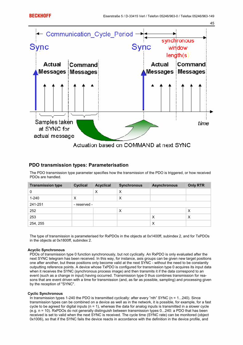
PDO transmission types: Parameterisation The PDO transmission type parameter specifies how the transmission of the PDO is triggered, or how received PDOs are handled.
Transmission type Cyclical Acyclical Synchronous Asynchronous Only RTR 0 X X
1-240 X X
241-251 - reserved -
252 X X
253 X X
254, 255 X
The type of transmission is parameterised for RxPDOs in the objects at 0x1400ff, subindex 2, and for TxPDOs in the objects at 0x1800ff, subindex 2.
Acyclic Synchronous PDOs of transmission type 0 function synchronously, but not cyclically. An RxPDO is only evaluated after the next SYNC telegram has been received. In this way, for instance, axis groups can be given new target positions one after another, but these positions only become valid at the next SYNC - without the need to be constantly outputting reference points. A device whose TxPDO is configured for transmission type 0 acquires its input data when it receives the SYNC (synchronous process image) and then transmits it if the data correspond to an event (such as a change in input) having occurred. Transmission type 0 thus combines transmission for rea-sons that are event driven with a time for transmission (and, as far as possible, sampling) and processing given by the reception of "SYNC".
Cyclic Synchronous In transmission types 1-240 the PDO is transmitted cyclically: after every ”nth” SYNC (n = 1...240). Since transmission types can be combined on a device as well as in the network, it is possible, for example, for a fast cycle to be agreed for digital inputs (n = 1), whereas the data for analog inputs is transmitted in a slower cycle (e.g. n = 10). RxPDOs do not generally distinguish between transmission types 0...240: a PDO that has been received is set to valid when the next SYNC is received. The cycle time (SYNC rate) can be monitored (object 0x1006), so that if the SYNC fails the device reacts in accordance with the definition in the device profile, and

Eiserstraße 5 / D-33415 Verl / Telefon 05246/963-0 / Telefax 05246/963-149
46
switches, for example, its outputs into the fault state.
The FC510x PC cards support cyclic synchronous transmission types completely: transmitting the SYNC tele-gram is coupled to the linked task, so that new input data is available every time the task begins. The card will recognise the absence of a synchronous PDO, and will report it to the application.
Only RTR Transmission types 252 and 253 apply to process data objects that are transmitted exclusively on request by a remote frame. 252 is synchronous: when the SYNC is received the process data is acquired. It is only transmit-ted on request. 253 is asynchronous. The data here is acquired continuously, and transmitted on request. This type of transmission is not generally recommended, because fetching input data from some CAN controllers is only partially supported. Because, furthermore, the CAN controllers sometimes answer remote frames auto-matically (without first requesting up-to-date input data), there are circumstances in which it is questionable whether the polled data is up-to-date. Transmission types 252 and 253 are for this reason not supported by the Beckhoff PC cards.
Asynchronous The transmission types 254 + 255 are asynchronous, but may also be event-driven. In transmission type 254, the event is specific to the manufacturer, whereas for type 255 it is defined in the device profile. In the simplest case, the event is the change of an input value - this means that every change in the value is transmitted.The asynchronous transmission type can be coupled with the event timer, thus also providing input data when no event has just occurred.
Inhibit time The ”inhibit time” parameter can be used to implement a ”transmit filter” that does not increase the reaction time for relatively new input alterations, but is active for changes that follow immediately afterwards. The inhibit time (transmit delay time) specifies the minimum length of time that must be allowed to elapse between the trans-mission of two of the same telegrams. If the inhibit time is used, the maximum bus loading can be determined, so that the worst case latency can then be found.
Although the Beckhoff FC510x PC cards can parameterise the inhibit time on slave devices, they do not them-selves support it. The transmitted PDOs become automatically spread out (transmit delay) as a result of the selected PLC cycle time - and there is little value in having the PLC run faster than the bus bandwidth permits. The bus loading, furthermore, can be significantly affected by the synchronous communication.
Event Timer An event timer for transmit PDOs can be specified by subindex 5 in the communication parameters. Expiry of this timer is treated as an additional event for the corresponding PDO, so that the PDO will then be transmitted. If the application event occurs during a timer period, it will also be transmitted, and the timer is reset.
Eiserstraße 5 / D-33415 Verl / Telefon 05246/963-0 / Telefax 05246/963-149
47
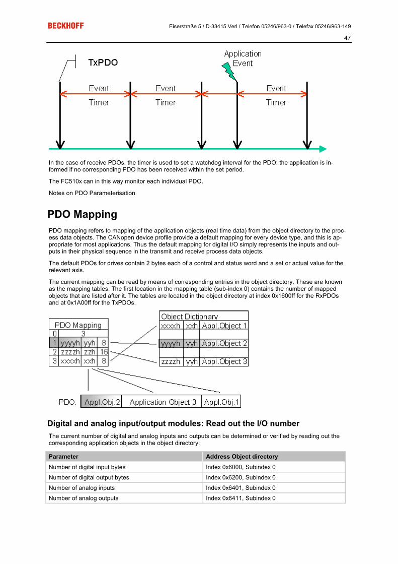
In the case of receive PDOs, the timer is used to set a watchdog interval for the PDO: the application is in-formed if no corresponding PDO has been received within the set period.
The FC510x can in this way monitor each individual PDO.
Notes on PDO Parameterisation
PDO Mapping PDO mapping refers to mapping of the application objects (real time data) from the object directory to the proc-ess data objects. The CANopen device profile provide a default mapping for every device type, and this is ap-propriate for most applications. Thus the default mapping for digital I/O simply represents the inputs and out-puts in their physical sequence in the transmit and receive process data objects.
The default PDOs for drives contain 2 bytes each of a control and status word and a set or actual value for the relevant axis.
The current mapping can be read by means of corresponding entries in the object directory. These are known as the mapping tables. The first location in the mapping table (sub-index 0) contains the number of mapped objects that are listed after it. The tables are located in the object directory at index 0x1600ff for the RxPDOs and at 0x1A00ff for the TxPDOs.
Digital and analog input/output modules: Read out the I/O number The current number of digital and analog inputs and outputs can be determined or verified by reading out the corresponding application objects in the object directory:
Parameter Address Object directory Number of digital input bytes Index 0x6000, Subindex 0
Number of digital output bytes Index 0x6200, Subindex 0
Number of analog inputs Index 0x6401, Subindex 0
Number of analog outputs Index 0x6411, Subindex 0

Eiserstraße 5 / D-33415 Verl / Telefon 05246/963-0 / Telefax 05246/963-149
48
Variable mapping As a rule, the default mapping of the process data objects already satisfies the requirements. For special types of application the mapping can nevertheless be altered: the Beckhoff CANopen Bus Couplers, for instance, thus support variable mapping, in which the application objects (input and output data) can be freely allocated to the PDOs. The mapping tables must be configured for this: as from Version 4 of CANopen, only the following procedure is permitted, and must be followed precisely:
1. First delete the PDO (set 0x1400ff, or 0x1800ff, subindex 1, bit 31 to "1")
2. Set subindex 0 in the mapping parameters (0x1600ff or 0x1A00ff) to "0"
3. Change mapping entries (0x1600ff or 0x1A00ff, SI 1..8)
4. Set subindex 0 in the mapping parameters to the valid value. The device then checks the entries for consis-tency.
5. Create PDO by entering the identifier (0x1400ff or 0x1800ff, subindex 1).
Dummy Mapping A further feature of CANopen is the mapping of placeholders, or dummy entries. The data type entries stored in the object directory, which do not themselves have data, are used as placeholders. If such entries are con-tained in the mapping table, the corresponding data from the device is not evaluated. In this way, for instance, a number of drives can be supplied with new set values using a single CAN telegram, or outputs on a number of nodes can be set simultaneously, even in event-driven mode.

Eiserstraße 5 / D-33415 Verl / Telefon 05246/963-0 / Telefax 05246/963-149
49
PDO Parameterisation Even though the majority of CANopen networks operate satisfactorily with the default settings, i.e. with the mi-nimum of configuration effort, it is wise at least to check whether the existing bus loading is reasonable: 80% bus loading may be acceptable for a network operating purely in cyclic synchronous modes, but for a network with event-driven traffic this value would generally be too high, as there is hardly any bandwidth available for additional events.
Consider the Requirements of the Application The communication of the process data must be optimised in the light of application requirements which are likely to be to some extent in conflict. These include
�� Little work on parameterisation - useable default values are optimal
�� Guaranteed reaction time for specific events
�� Cycle time for regulation processes over the bus
�� Safety reserves for bus malfunctions (enough bandwidth for the repetition of messages)
�� Maximum baud rate - depends on the maximum bus length
�� Desired communication paths - who is speaking with whom
The determining factor often turns out to be the available bus bandwidth (bus load).
Baud rate We generally begin by choosing the highest baud rate that the bus will permit. It should be borne in mind that serial bus systems are always more sensitive to interference at higher baud rates, so the better rule is "just as fast as needed". 1000 kbit/s are not usually necessary, and only to be unreservedly recommended on networks within a control cabinet where there is no electrical isolation between the bus nodes. Experience also tends to show that estimates of the length of bus cable laid are often over-optimistic - the length actually laid tends to be longer.
Determine the Communication Type Once the baud rate has been chosen it is appropriate to specify the PDO communication type(s). These have different advantages and disadvantages:
�� Cyclic synchronous communication provides an accurately predictable bus loading, and therefore a de-fined time behaviour - you could say that the standard case is the worst case. It is easy to configure: The SYNC rate parameter sets the bus loading globally. The process images are synchronised: Inputs are read at the same time, output data is set valid simultaneously, although the quality of the synchro-nisation depends on the implementation. The Beckhoff FC510x PC cards are capable of synchronising the CANopen bus system with the cycles of the application program (PLC or NC). The guaranteed reaction time under cyclic synchronous communication is always at least as long as the cycle time, and the bus bandwidth is not exploited optimally, since "old" data, i.e. data that has not changed, is continuously transmitted. It is however possible to optimise the network through the selec-tion of different SYNC multiples (transmission types 1...240), so that data that changes slowly is transmitted less often than, for instance, time-critical inputs. It must, however, be borne in mind that input states that last for a time that is shorter than the cycle time will not necessarily be communicated. If it is necessary for such conditions to be registered, the associated PDOs for asynchronous commu-nication should be provided.
�� Event-driven asynchronous communication is optimal from the point of view of reaction time and the exploitation of bus bandwidth - it can be described as "pure CAN". Your choice must, however, also take account of the fact that it is not impossible for a large number of events to occur simultaneously, leading to corresponding delays before a PDO with a relatively low priority can be sent. Proper net-work planning therefore necessitates a worst-case analysis. Through the use of, for instance inhibit time it is also necessary to prevent a constantly changing input with a high PDO priority from blocking the bus (technically known as a "babbling idiot"). It is for this reason that event driving is switched off by default in the device profile of analog inputs, and must be turned on specifically. Time windows for

Eiserstraße 5 / D-33415 Verl / Telefon 05246/963-0 / Telefax 05246/963-149
50
the transmit PDOs can be set using progress timers: the telegram is not sent again before the inhibit time has elapsed, and not later than the time required for the progress timer to complete.
�� The communication type is parameterised by means of the transmission type.
It is also possible to combine the two PDO principles. It can, for instance, be helpful to exchange the set and actual values of an axis controller synchronously, while limit switches, or motor temperatures with limit values are monitored with event-driven PDOs. This combines the advantages of the two principles: synchronicity for the axis communication and short reaction times for limit switches. In spite of being event-driven, the distributed limit value monitoring avoids a constant addition to the bus load from the analog temperature value.
In this example it can also be of value to deliberately manipulate the identifier allocation, in order to optimise bus access by means of priority allocation: the highest priority is given to the PDO with the limit switch data, and the lowest to that with the temperature values.
Optimisation of bus access latency time through modification of the identifier allocation is not, however, nor-mally required. On the other hand the identifiers must be altered if "masterless" communication is to be made possible (PDO linking). In this example it would be possible for one RxPDO for each axis to be allocated the same identifier as the limit switch TxPDO, so that alterations of the input value can be received without delay.
Determining the Bus Loading It is always worth determining the bus loading. But what bus loading values are "permitted", or indeed sensible? It is first necessary to distinguish a short burst of telegrams in which a number of CAN messages follow one another immediately - a temporary 100% bus loading. This is only a problem if the sequence of receive inter-rupts that it caused at the CAN nodes can not be handled. This would constitute a data overflow (or "CAN queue overrun"). This can occur at very high baud rates (> 500 kbit/s) at nodes with software telegram filtering and relatively slow or heavily loaded microcontrollers if, for instance, a series of remote frames (which do not contain data bytes, and are therefore very short) follow each other closely on the bus (at 1 Mbit/s this can gen-erate an interrupt every 40 µs; for example, an NMT master might transmit all its guarding requests in an un-broken sequence). This can be avoided through skilled implementation, and the user should be able to assume that the device suppliers have taken the necessary trouble. A burst condition is entirely normal immediately after the SYNC telegram, for instance: triggered by the SYNC, all the nodes that are operating synchronously try to send their data at almost the same time. A large number of arbitration processes take place, and the tele-grams are sorted in order of priority for transmission on the bus. This is not usually critical, since these tele-grams do contain some data bytes, and the telegrams trigger a sequence of receive interrupts at the CAN no-des which is indeed rapid, but is nevertheless manageable.
Bus loading most often refers to the value averaged over several primary cycles, that is the mean value over 100-500 ms. CAN, and therefore CANopen, is indeed capable of managing a bus loading of close to 100% over long periods, but this implies that no bandwidth is available for any repetitions that may be necessitated by in-terference, for asynchronous error messages, parameterisation and so on. Clearly, the dominant type of com-munication will have a large influence on the appropriate level of bus loading: a network with entirely cyclic syn-chronous operation is always in any case near to the "worst case" state, and can therefore be operated with values in the 70-80% range. The figure is very hard to state for an entirely event-driven network: an estimate must be made of how many events additional to the current state of the system might occur, and of how long the resulting burst might last - in other words, for how long the lowest priority message will be delayed. If this value is acceptable to the application, then the current bus loading is acceptable. As a rule of thumb it can usu-ally be assumed that an event-driven network running with a base loading of 30-40% has enough reserve for worst-case scenarios, but this assumption does not obviate the need for a careful analysis if delays could have critical results for the plant.
The Beckhoff FC510x PC cards indicate the bus loading via the System Manager. This variable can also be processed in the PLC, or can be displayed in the visualisation system.
The amount data in the process data objects is of course as relevant as the communication parameters: the PDO mapping.

Eiserstraße 5 / D-33415 Verl / Telefon 05246/963-0 / Telefax 05246/963-149
51
Service Data Objects (SDO) The parameters listed in the object directory are read and written by means of service data objects. These SDOs are multiplexed domains, i.e. structures of any size that have a multiplexer (address). The multiplexer consists of a 16-bit index and an 8-bit sub-index that address the corresponding entries in the object directory.
SDO protocol: access to the object directory
The CANopen bus couplers are servers for the SDO, which means that at the request of a client (e.g. of the IPC or the PLC) they make data available (upload), or they receive data from the client (download). This in-volves a handshake between the client and the server.
When the size of the parameter to be transferred is not more than 4 bytes, a single handshake is sufficient (one telegram pair): For a download, the client sends the data together with its index and sub-index, and the server confirms reception. For an upload, the client requests the data by transmitting the index and sub-index of the desired parameter, and the server sends the parameter (including index and sub-index) in its answer telegram.
The same pair of identifiers is used for both upload and download. The telegrams, which are always 8 bytes long, encode the various services in the first data byte. All parameters with the exception of objects 1008h, 1009h and 100Ah (device name, hardware and software versions) are only at most 4 bytes long, so this de-scription is restricted to transmission in expedited transfer.
Protocol The structure of the SDO telegrams is described below.
Client -> Server, Upload Request 11 bit identifier 8 byte of user data
0x600 (=1536dez) + node ID 0x40 Index0 Index1 SubIdx 0x00 0x00 0x00 0x00
Parameters Explanation Index0 Index low byte (Unsigned16, LSB)
Index1 Index high byte (Unsigned16, MSB)
SubIdx Subindex (Unsigned8)

Eiserstraße 5 / D-33415 Verl / Telefon 05246/963-0 / Telefax 05246/963-149
52
Client -> Server, Upload Response 11 bit identifier 8 byte of user data
0x580 (=1408dez) + node ID 0x4x Index0 Index1 SubIdx Data0 Data1 Data2 Data3
Parameters Explanation Index0 Index low byte (Unsigned16, LSB)
Index1 Index high byte (Unsigned16, MSB)
SubIdx Subindex (Unsigned8)
Data0 Data low low byte (LLSB)
Data3 Data high high byte (MMSB) Parameters whose data type is Unsigned8 are transmitted in byte D0, parameters whose type is Unsigned16 use D0 and D1.
The number of valid data bytes is coded as follows in the first CAN data byte (0x4x):
Number of parameter bytes 1 2 3 4 First CAN data byte 0x4F 0x4B 0x47 0x43
Client -> Server, Download Request 11 bit identifier 8 byte of user data
0x600 (=1536dez) + node ID 0x22 Index0 Index1 SubIdx Data0 Data1 Data2 Data3
Parameters Explanation Index0 Index low byte (Unsigned16, LSB)
Index1 Index high byte (Unsigned16, MSB)
SubIdx Subindex (Unsigned8)
Data0 Data low low byte (LLSB)
Data3 Data high high byte (MMSB)
It is optionally possible to give the number of valid parameter data bytes in the first CAN data byte
Number of parameter bytes 1 2 3 4 First CAN data byte 0x2F 0x2B 0x27 0x23 This is, however, not generally necessary, since only the less significant data bytes up to the length of the ob-ject directory entry that is to be written are evaluated. A download of data up to 4 bytes in length can therefore always be achieved in Beckhoff bus nodes with 22h in the first CAN data byte.
Client -> Server, Download Response 11 bit identifier 8 byte of user data
0x580 (=1408dez) + node ID 0x60 Index0 Index1 SubIdx 0x00 0x00 0x00 0x00
Parameters Explanation Index0 Index low byte (Unsigned16, LSB)
Index1 Index high byte (Unsigned16, MSB)
SubIdx Subindex (Unsigned8)

Eiserstraße 5 / D-33415 Verl / Telefon 05246/963-0 / Telefax 05246/963-149
53
Abortion of Parameter Communication Parameter communication is interrupted if it is faulty. The client or server send an SDO telegram with the following structure for this purpose:
11 bit identifier 8 byte of user data
0x580 (client) or 0x600(server) + node ID
0x80 Index0 Index1 SubIdx Error0 Error1 Error2 Error3
Parameters Explanation Index0 Index low byte (Unsigned16, LSB)
Index1 Index high byte (Unsigned16, MSB)
SubIdx Subindex (Unsigned8)
Error0 SDO error code low low byte (LLSB)
Error3 SDO error code high high byte (MMSB)
List of SDO error codes (reason for abortion of the SDO transfer):
SDO error code Explanation 0x05 03 00 00 Toggle bit not changed
0x05 04 00 01 SDO command specifier invalid or unknown
0x06 01 00 00 Access to this object is not supported
0x06 01 00 02 Attempt to write to a Read_Only parameter
0x06 02 00 00 The object is not found in the object directory
0x06 04 00 41 The object can not be mapped into the PDO
0x06 04 00 42 The number and/or length of mapped objects would exceed the PDO length
0x06 04 00 43 General parameter incompatibility
0x06 04 00 47 General internal error in device
0x06 06 00 00 Access interrupted due to hardware error
0x06 07 00 10 Data type or parameter length do not agree or are unknown
0x06 07 00 12 Data type does not agree, parameter length too great
0x06 07 00 13 Data type does not agree, parameter length too short
0x06 09 00 11 Subindex not present
0x06 09 00 30 General value range error
0x06 09 00 31 Value range error: parameter value too great
0x06 09 00 32 Value range error: parameter value too small
0x06 0A 00 23 Resource not available
0x08 00 00 21 Access not possible due to local application
0x08 00 00 22 Access not possible due to current device status
Further, manufacturer-specific error codes have been introduced for register communication (index 0x4500, 0x4501):
SDO error code Explanation 0x06 02 00 11 Invalid table: Table or channel not present
0x06 02 00 10 Invalid register: table not present
0x06 01 00 22 Write protection still set
0x06 07 00 43 Incorrect number of function arguments
0x06 01 00 21 Function still active, try again later

Eiserstraße 5 / D-33415 Verl / Telefon 05246/963-0 / Telefax 05246/963-149
54
0x05 04 00 40 General routing error
0x06 06 00 21 Error accessing BC table
0x06 09 00 10 General error communicating with terminal
0x05 04 00 47 Time-out communicating with terminal

Eiserstraße 5 / D-33415 Verl / Telefon 05246/963-0 / Telefax 05246/963-149
55
FC5101: SDO Communication CANopen SDO (Service Data Object) communication is used to read or write any parameters in the CANopen bus node's object directory. The FC5101CANopen PCI card uses SDO communication to configure the com-munication parameters when starting up. Two types of application-specific SDO communication are additionally possible:
1. Downloading Application-Specific Parameters when Starting Up The appropriate parameters are to be entered here in the System Manager for the corresponding node under "SDO". The objects that result from the configuration under CAN node appear in square brackets. Any desired number of object directory entries can then be inserted.
The card expects a positive acknowledgement of the parameter download from the relevant bus device. If it was not possible to write a parameter (the bus device has aborted the SDO) the card then attempts to read the corresponding value back and to compare it with the value that was to be written. This is because it could, for instance, be a read-only value, and therefore already correctly configured within the bus device. If they agree with one another, the card moves onto the next parameter entry.
2. Upload and Download at Runtime via ADS It is possible to perform SDO accesses to the bus devices' object directories using Beckhoff's ADS communica-tion when the system is running. This is also possible from the PLC, from the NC, from the OPC server, from ActiveX controls or from any other ADS device.
The whole SDO protocol is handled by the card. Using the ADS Write or ADS Read functions the parameters are transferred to the card, and the data is transferred (write) or fetched (read). The "IDXGRP" parameter here corresponds to the 16 bit index in the CANopen object directory, while "IDXOFFS" corresponds to the 8 bit sub-index in the CANopen object directory. Detailed information about the ADS function blocks may be found in the TwinCAT documentation (TwinCAT Information System).
The ADS function block parameters are represented as follows in the SDO parameters:

Eiserstraße 5 / D-33415 Verl / Telefon 05246/963-0 / Telefax 05246/963-149
56
ADSREAD / ADSWRITE Parameters Description NETID The NetID is a string, 23 bytes in length, and is formed by default from the IP address of
the computer with an additional two bytes. It addresses the FC5101 card and can be found under "ADS" in the System Manager.
PORT Contains the ADS device's port number - this is the port number of the CANopen bus device that is to be addressed.
IDXGRP Corresponds to the 16 bit index in the CANopen object directory. IDXOFFS Corresponds to the 8 bit sub-index in the CANopen object directory. LEN The length of the parameter that is to be read or written, in bytes.
DESTADDR (only ADS-READ)
Contains the address of the buffer which is to receive the data that has been read. The programmer is himself responsible for dimensioning the buffer to a size that can accept ‘LEN’ bytes. The buffer can be a single variable, an array or a structure, whose address can be found with the ADR operator.
SRCADDR (only ADSWRITE)
Contains the address of the buffer from which the data to be written is to be fetched. The programmer is himself responsible for dimensioning the buffer to such a size that ‘LEN’ bytes can be taken from it. The buffer can be a single variable, an array or a structure, whose address can be found with the ADR operator.
READ The ADS command is triggered by a rising edge at this input.
TIMEOUT States the time before the function is cancelled.
BUSY This output remains TRUE until the block has executed a command, but at the longest for the duration supplied to the ‘Timeout’ input. While Busy = TRUE, no new command will be accepted at the inputs. Please note that it is not the execution of the service but its accep-tance whose time is monitored.
ERR This output is switched to TRUE if an error occurs during the execution of the command.
ERRID Contains the command-specific error code of the most recently executed command. Is reset to 0 by the execution of an instruction at the inputs.
The ERRID contains the general ADS ERROR CODES in the low word and the SDO-specific error codes in the high word:
Bits 0...3 contain the SDO error class
Bits 4..7 contain the SDO error code
Bits 8...14 contain the additional code for the SDO abort
Bit 15 is always 1
Example: SDO Read via ADS In the following example program (structured text) for the use of ADS services for SDO communication, object 0x1000, sub-index 0, from the node with port number 0x1001 is read. The DeviceType is CANopen. This is coded as UnSigned32, and is therefore 4 bytes long.
SDO_READ( StartReading := ReadStart, CO_Index := 16#1000, CO_SubIndex := 16#0, DataLength := 4, PortNr := 16#1001, ADSNetID:='192.168.10.11.2.1' );
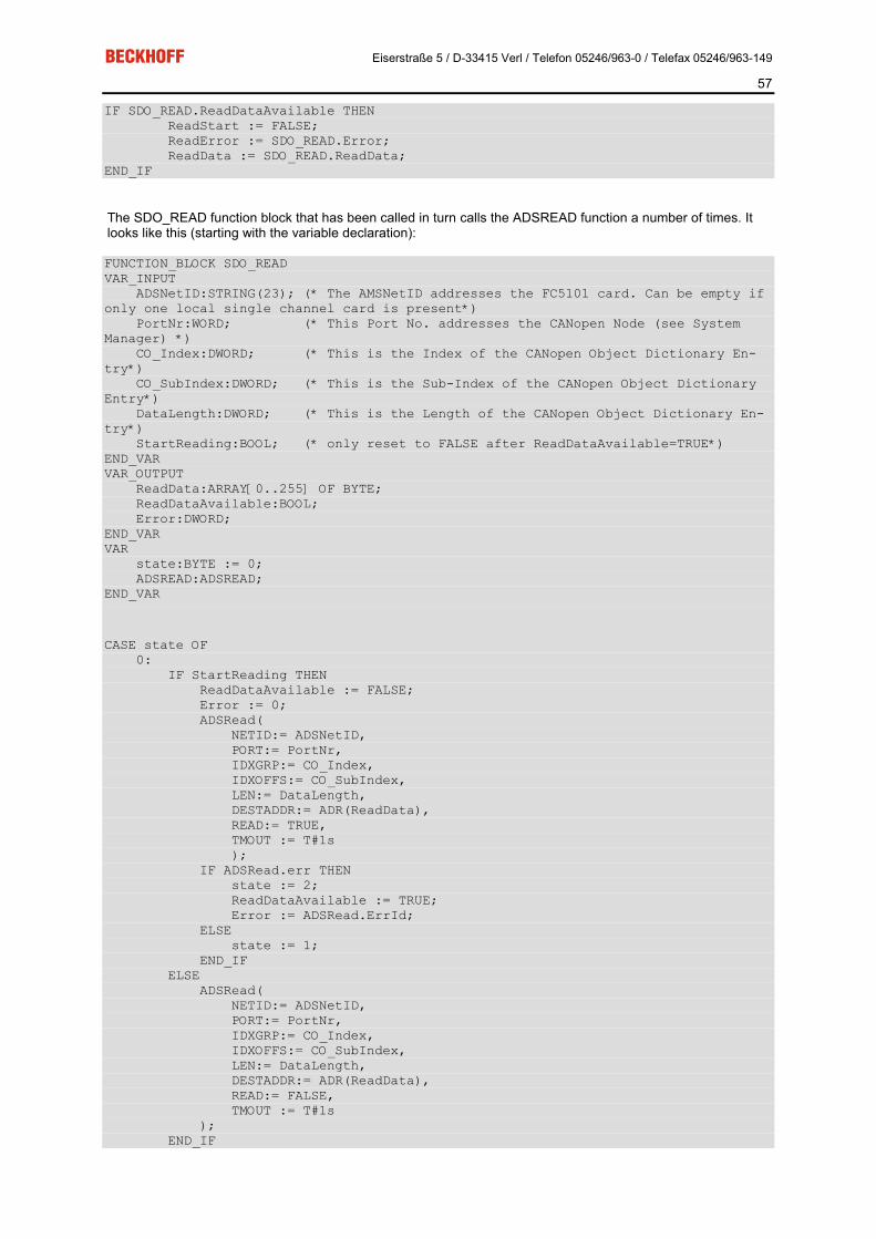
Eiserstraße 5 / D-33415 Verl / Telefon 05246/963-0 / Telefax 05246/963-149
57
IF SDO_READ.ReadDataAvailable THEN ReadStart := FALSE; ReadError := SDO_READ.Error; ReadData := SDO_READ.ReadData; END_IF
The SDO_READ function block that has been called in turn calls the ADSREAD function a number of times. It looks like this (starting with the variable declaration):
FUNCTION_BLOCK SDO_READ VAR_INPUT ADSNetID:STRING(23); (* The AMSNetID addresses the FC5101 card. Can be empty if only one local single channel card is present*) PortNr:WORD; (* This Port No. addresses the CANopen Node (see System Manager) *) CO_Index:DWORD; (* This is the Index of the CANopen Object Dictionary En-try*) CO_SubIndex:DWORD; (* This is the Sub-Index of the CANopen Object Dictionary Entry*) DataLength:DWORD; (* This is the Length of the CANopen Object Dictionary En-try*) StartReading:BOOL; (* only reset to FALSE after ReadDataAvailable=TRUE*) END_VAR VAR_OUTPUT ReadData:ARRAY[0..255] OF BYTE; ReadDataAvailable:BOOL; Error:DWORD; END_VAR VAR state:BYTE := 0; ADSREAD:ADSREAD; END_VAR
CASE state OF 0: IF StartReading THEN ReadDataAvailable := FALSE; Error := 0; ADSRead( NETID:= ADSNetID, PORT:= PortNr, IDXGRP:= CO_Index, IDXOFFS:= CO_SubIndex, LEN:= DataLength, DESTADDR:= ADR(ReadData), READ:= TRUE, TMOUT := T#1s ); IF ADSRead.err THEN state := 2; ReadDataAvailable := TRUE; Error := ADSRead.ErrId; ELSE state := 1; END_IF ELSE ADSRead( NETID:= ADSNetID, PORT:= PortNr, IDXGRP:= CO_Index, IDXOFFS:= CO_SubIndex, LEN:= DataLength, DESTADDR:= ADR(ReadData), READ:= FALSE, TMOUT := T#1s ); END_IF

Eiserstraße 5 / D-33415 Verl / Telefon 05246/963-0 / Telefax 05246/963-149
58
1: ADSRead(READ:= FALSE); IF ADSRead.err THEN state := 2; ReadDataAvailable := TRUE; Error := ADSRead.ErrId; ELSE IF NOT ADSRead.busy THEN state := 2; ReadDataAvailable := TRUE; END_IF END_IF 2: ADSRead(READ:= FALSE); state := 0; END_CASE
Example: SDO Write via ADS In the following example program (structured text) for the use of ADS services for SDO communication, object 0x6200, sub-index 3, from the node with port number 0x1001 is written. It concerns digital outputs to an I/O node.
(* Data to be written *) WriteData[0] := 16#55; (* write Object *) SDO_WRITE( StartWriting := WriteStart, CO_Index := 16#6200, CO_SubIndex := 3, DataLength := 1, PortNr := 16#1001, WriteData := WriteData, ADSNetID:='192.168.10.11.2.1' ); IF SDO_WRITE.WriteDataFinished THEN WriteStart := FALSE; WriteError := SDO_WRITE.Error; END_IF
The SDO_WRITE function block that has been called in turn calls the ADSWRITE function a number of times. It looks like this (starting with the variable declaration):
FUNCTION_BLOCK SDO_WRITE VAR_INPUT ADSNetID:STRING(23); (* The AMSNetID addresses the FC5101 card. Can be empty if only one local single channel card is present*) PortNr:WORD; (* The Port No. addresses the CANopen Node (see System Manager) *) CO_Index:DWORD; (* This is the Index of the CANopen Object Dictionary Entry*) CO_SubIndex:DWORD; (* This is the Sub-Index of the CANopen Object Dictionary Entry*) DataLength:DWORD; (* This is the Length of the CANopen Object Dictionary Entry*) StartWriting:BOOL; (* only reset to FALSE after WriteDataFinished=TRUE*) WriteData:ARRAY[0..255] OF BYTE; (*This array contains the data to be written to the CANopen Object Dictionary*) END_VAR VAR_OUTPUT WriteDataFinished:BOOL; Error:DWORD; END_VAR VAR state:BYTE := 0; ADSWRITE:ADSWRITE; END_VAR
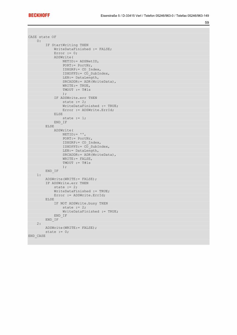
Eiserstraße 5 / D-33415 Verl / Telefon 05246/963-0 / Telefax 05246/963-149
59
CASE state OF 0: IF StartWriting THEN WriteDataFinished := FALSE; Error := 0; ADSWrite( NETID:= ADSNetID, PORT:= PortNr, IDXGRP:= CO_Index, IDXOFFS:= CO_SubIndex, LEN:= DataLength, SRCADDR:= ADR(WriteData), WRITE:= TRUE, TMOUT := T#1s ); IF ADSWrite.err THEN state := 2; WriteDataFinished := TRUE; Error := ADSWrite.ErrId; ELSE state := 1; END_IF ELSE ADSWrite( NETID:= '', PORT:= PortNr, IDXGRP:= CO_Index, IDXOFFS:= CO_SubIndex, LEN:= DataLength, SRCADDR:= ADR(WriteData), WRITE:= FALSE, TMOUT := T#1s ); END_IF 1: ADSWrite(WRITE:= FALSE); IF ADSWrite.err THEN state := 2; WriteDataFinished := TRUE; Error := ADSWrite.ErrId; ELSE IF NOT ADSWrite.busy THEN state := 2; WriteDataFinished := TRUE; END_IF END_IF 2: ADSWrite(WRITE:= FALSE); state := 0; END_CASE

Eiserstraße 5 / D-33415 Verl / Telefon 05246/963-0 / Telefax 05246/963-149
60
Baud rate + Bit Timing The following baud rates and entries in the bit-timing register are supported by the CANopen devices:
Baud rate [kbaud] BTR0 BTR1 Sampling Point 1000 0x00 0x14 75%
800 0x00 0x16 80%
500 0x00 0x1C 87%
250 0x01 0x1C 87%
125 0x03 0x1C 87%
100 0x04 0x1C 87%
50 0x09 0x1C 87%
20 0x18 0x1C 87%
10 0x31 0x1C 87%
The bit-timing register settings given (BTR0, BTR1) apply, for example, for the Philips 82C200, SJA1000, Intel 80C527, Siemens 80C167 and other CAN controllers. They are optimised for the maximum bus length.

Eiserstraße 5 / D-33415 Verl / Telefon 05246/963-0 / Telefax 05246/963-149
61
Identifier Allocation
Default identifier CANopen provides default identifiers for the most important communication objects, and these are derived from the 7-bit node address (the node ID) and a 4-bit function code in accordance with the following scheme:
For broadcast objects the node ID is set to ”0”. This gives rise to the following default identifiers:
Broadcast objects
Object Function Function Code
Resuting COB ID hex / dez
Object for Comm. Parameter / mapping
NMT Boot-Up 0 0x00 / 0 - / -
SYNC Synchronisation 1 0x80 / 128 0x1005 + 0x1006 / -
Peer-to-Peer-Objects
Object Function Function Code
Resulting COB ID hex / dez
Objekt für Comm. Parameter / Mapping
Emergency Status / Error 1 0x81 - 0xFF/ 129 - 255 - / -
PDO1 (tx) dig. inputs 11 0x181 - 0x1FF / 385 - 511 0x1800 / 0x1A00
PDO1 (rx) digital outputs 100 0x201 - 0x27F/ 513-639 0x1400 / 0x1600
PDO2 (tx) analog inputs 101 0x281 - 0x2FF/ 641-767 0x1801 / 0x1A01
PDO2 (rx) analog outputs 110 0x301 - 0x37F/ 769-895 0x1401 / 0x1601
PDO3 (tx) analog inputs* 111 0x381 - 0x3FF / 897 - 1023
0x1802 / 0x1A02
PDO3 (rx) analog outputs* 1000 0x401 - 0x47F/ 1025 - 1151
0x1402 / 0x1602
PDO4 (tx) analog inputs* 1001 0x481 - 0x4FF/ 1153 - 1279
0x1803 / 0x1A03
PDO4 (rx) analog outputs* 1010 0x501 - 0x57F/ 1281 - 1407
0x1403 / 0x1603
SDO (tx) Parameters 1011 0x581 - 0x5FF/ 1409-1535 - / -
SDO (rx) Parameters 1100 0x601 - 0x67F/ 1537-1663 - / -
Guarding Life-/Node-guarding, Heartbeat, Boot-Up mes-sage
1110 0x701 - 0x77F/ 1793-1919 (0x100C, 0x100D, 0x100E, 0x1016, 0x1017)
* For historical reasons, the Beckhoff default mapping applies to PDOs 3 and 4 in Beckhoff I/O devices. In most configurations, PDOs 3 and 4 contain data related to analog inputs and outputs, but there can also be "excess" data from digital I/Os, or data from special terminals. Details may be found in the Bus Coupler documentation.
Up until version 3 of the CANopen specification, default identifiers were assigned to 2 PDOs at a time. The Beckhoff Bus Couplers correspond to this issue of the specification. After version 4, default identifiers are pro-vided for up to 4 PDOs.

Eiserstraße 5 / D-33415 Verl / Telefon 05246/963-0 / Telefax 05246/963-149
62
6. Error Handling and Diagnosis Beckhoff FC510x LED Description
LED Behavior The red ERROR LED and the green RUN help to quickly diagnose the status of the card:
Error LED (red)
Run LED (green) Description
off off TwinCAT has been stopped
off on All configured bus nodes are error free (Box State=0), TwinCAT Task or Process is running.
off blinking with 2 Hz
The Task, whose process data is linked to the card, is not running. All configured bus nodes have been found and are error free (Box State=0)
blinking with 2Hz
on At least one box state is unequal zero (e.g. node not found, wrong configura-tion, node in error), TwinCAT Task is running
blinking with 2 Hz
off At least one box state is unequal zero (e.g. node not found, wrong configura-tion, node in error), TwinCAT Task is not running
on off TwinCAT is running, CAN Controller is "Bus OFF". Physical CAN problem. Possible reasons: e.g. terminating resistor missing, bus too long, wrong baud rate, node address configured twice, short circuit, wiring error. Restart is necessary
blinking with 20Hz
blinking with 20Hz
Configuration Upload is under way
blinking with 20Hz
off card is in STOP mode
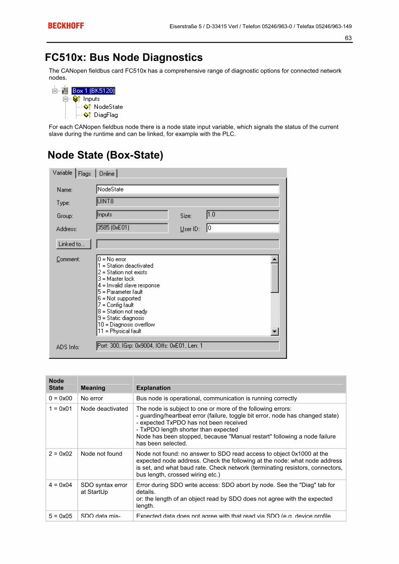
Eiserstraße 5 / D-33415 Verl / Telefon 05246/963-0 / Telefax 05246/963-149
63
FC510x: Bus Node Diagnostics The CANopen fieldbus card FC510x has a comprehensive range of diagnostic options for connected network nodes.
For each CANopen fieldbus node there is a node state input variable, which signals the status of the current slave during the runtime and can be linked, for example with the PLC.
Node State (Box-State)
Node State Meaning Explanation 0 = 0x00 No error Bus node is operational, communication is running correctly
1 = 0x01 Node deactivated The node is subject to one or more of the following errors: - guarding/heartbeat error (failure, toggle bit error, node has changed state) - expected TxPDO has not been received - TxPDO length shorter than expected Node has been stopped, because "Manual restart" following a node failure has been selected.
2 = 0x02 Node not found Node not found: no answer to SDO read access to object 0x1000 at the expected node address. Check the following at the node: what node address is set, and what baud rate. Check network (terminating resistors, connectors, bus length, crossed wiring etc.)
4 = 0x04 SDO syntax error at StartUp
Error during SDO write access: SDO abort by node. See the "Diag" tab for details. or: the length of an object read by SDO does not agree with the expected length.
5 = 0x05 SDO data mis- Expected data does not agree with that read via SDO (e.g. device profile

Eiserstraße 5 / D-33415 Verl / Telefon 05246/963-0 / Telefax 05246/963-149
64
match at StartUp and/or additional info do not agree with object 0x1000). Can also occur if the value to be written (e.g. PDO COB-ID) is read back due to refusal of write access, and does not agree. See the "Diag" tab for details.
8 = 0x08 Node StartUp in progress
Node was found and has been started.
11 = 0x0B
FC510x Bus-OFF CAN chip has entered the "Bus-OFF" state: transmit error counter is running
12 = 0x0C
Pre-Operational Node has gone pre-operational (on its own account).
13 = 0x0D
Severe bus fault General firmware error.
14 = 0x0E
Guarding: toggle error
Guarding error: Toggle bit has not changed.
20 = 0x14
TxPDO too short Received TxPDO shorter than expected.
22 = 0x16
Expected TxPDO is missing
TxPDO has not been received within the expected time interval: - sync interval with synchronous TxPDOs, - event timer with event-driven PDOs).
23 = 0x17
Node is Opera-tional but not all TxPDOs were received
Node has been started, but at least one TxPDO has not yet been received from the node. Possible causes (examples): - The node only sends event-driven PDOs after the first event (this is not the intention of the CANopen specification, but is quite usual). - Too many TxPDOs have been configured. - A TxPDO is present at the node, but no process data has been mapped. - The TxPDO has transmission type 1...120 (synchronous), but SYNC has not yet been sent because the associated task has not been started.
DiagFlag: Shows whether the box diagnostic information has changed.
Reading the Diagnostic Data via ADS CANopen emergencies and other diagnostic data can be read out via ADS read (new data present as soon as you see the DiagFlag). You need to enter the FC510x ADS net ID. Other ADS parameters:
Port: 200
IndexGroup: Lo-Word = 0xF180, Hi-Word = Node-Number.
IndexOffset: See below
Length: See below
If more than 26 bytes of diagnostic data have been read out the emergency memory is reset. The DiagFlag is reset as soon as at least 108 bytes have been read starting from offset 0. Alternatively, the flag is reset after each of read access, if IndexGroup 0xF181 (instead of 0xF180) is used for the read.
The diagnostic data have the following definitions:
Offset 0,1: Bit 1: Boot up message not received or incorrect
Bit 2: Emergency-Overflow
Bit 0, Bit 3-15: reserved
Offset 2,3: Bits 0-14: TX-PDO (i+1) received
Bit 15: All TX PDOs 16-n received
Offset 4,5: Bits 0-4: 1: Incorrect TX PDO length
2: Synchronous TX PDO absent
3: Node signalling PRE-OPERATIONAL
4: Event timer timed out for TX PDO
5: No response and guarding is activated

Eiserstraße 5 / D-33415 Verl / Telefon 05246/963-0 / Telefax 05246/963-149
65
6: Toggling missed several times and guarding activated
Bits 5-15: Associated COB ID
Offset 6: Bits 0-7: 1: Incorrect value during SDO upload
2: Incorrect length during SDO upload
3: Abort during SDO up/download
4: Incorrect date during a boot-up message
5: Timeout while waiting for a boot-up message
Offset 7: Bits 0-7: 2: Incorrect SDO command specifier
3: SDO toggle bit has not changed
4: SDO length too great
5: SDO-Abort
6: SDO-Timeout
Offset 8,9 Bits 0-7: SDO up/download index
Offset 10: Bits 0-7: SDO up/download sub-index
Offset 11: Bits 0-7: reserved
Offset 12: Bits 0-7: Abort errorClass
Offset 13: Bits 0-7: Abort errorCode
Offset 14,15: Bits 0-15: Abort additionalCode
Offset 16-19: Read value (if offset 6 = 1)
Offset 20-23: Expected value (if offset 6 = 1)
Offset 24-25: Number of consecutive emergencies
Offset 26 - n: Emergencies (8 bytes each)

Eiserstraße 5 / D-33415 Verl / Telefon 05246/963-0 / Telefax 05246/963-149
66
FC510x Diagnostics The FC510x CANopen fieldbus card makes extensive diagnostic facilities available for the input variables.
cycleCounter Is incremented after each firmware cycle. The PLC task can use this to establish whether new input data is being handled - if the cycleCounter has not been incremented since the last time the PLC task was called, the task time is too short.
error The number of nodes whose state is not zero.
actualCycleTime Current cycle time of the card firmware in 4/25 µs. Depends on the quantity of data and the bus loading.
DiagFlag Is set to 1 if new diagnostic data (such as emergency) has been placed in the card's memory.
GlobalState Reserved for internal evaluations.
LastAdsError Last ADS error to have occurred. See also ADS Error Codes.
CycleFailedCounter This counter is incremented if it was not possible to complete the card's firmware cycle before the highest prior-ity linked task accessed the DPRAM again. In this case, the task does not receive any new input data, nor are new synchronous PDOs issued in the previous cycle. Because the CycleFailedCounter is not incremented until after the corresponding task start, it cannot be used for diagnosis within that task. It is recommended that the cycleCounter be used here, as it is not incremented in these cases.
Busload Indicates the current bus loading in %.

Eiserstraße 5 / D-33415 Verl / Telefon 05246/963-0 / Telefax 05246/963-149
67
General Diag
The minimum and maximum bus loading are also displayed on the "General Diag" tab in addition to the current bus loading, as are the cycle time and the failed cycle counter. In the example illustrated above, about 5000 CAN frames are handled each second, and a corresponding number of PDOs are sent. Because the firmware sends all the pending PDOs in each cycle, the firmware cycle time in this case primarily depends on the time required to transmit the PDOs.
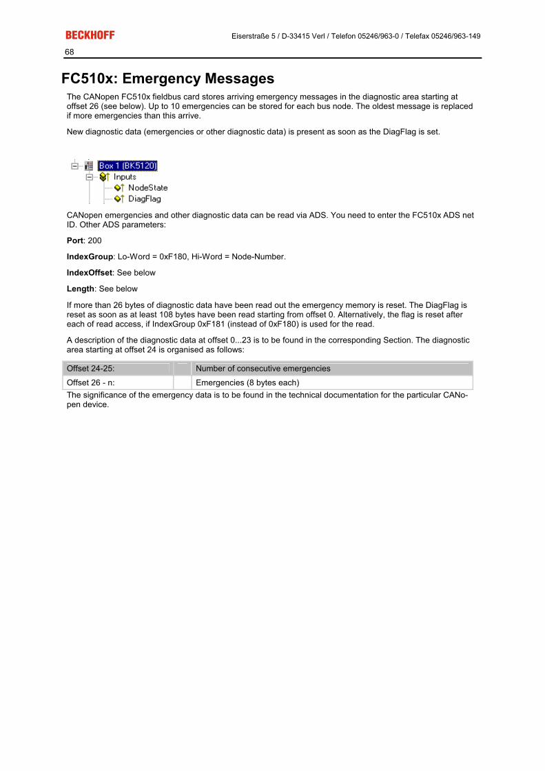
Eiserstraße 5 / D-33415 Verl / Telefon 05246/963-0 / Telefax 05246/963-149
68
FC510x: Emergency Messages The CANopen FC510x fieldbus card stores arriving emergency messages in the diagnostic area starting at offset 26 (see below). Up to 10 emergencies can be stored for each bus node. The oldest message is replaced if more emergencies than this arrive.
New diagnostic data (emergencies or other diagnostic data) is present as soon as the DiagFlag is set.
CANopen emergencies and other diagnostic data can be read via ADS. You need to enter the FC510x ADS net ID. Other ADS parameters:
Port: 200
IndexGroup: Lo-Word = 0xF180, Hi-Word = Node-Number.
IndexOffset: See below
Length: See below
If more than 26 bytes of diagnostic data have been read out the emergency memory is reset. The DiagFlag is reset as soon as at least 108 bytes have been read starting from offset 0. Alternatively, the flag is reset after each of read access, if IndexGroup 0xF181 (instead of 0xF180) is used for the read.
A description of the diagnostic data at offset 0...23 is to be found in the corresponding Section. The diagnostic area starting at offset 24 is organised as follows:
Offset 24-25: Number of consecutive emergencies
Offset 26 - n: Emergencies (8 bytes each) The significance of the emergency data is to be found in the technical documentation for the particular CANo-pen device.

Eiserstraße 5 / D-33415 Verl / Telefon 05246/963-0 / Telefax 05246/963-149
69
FC510x: ADS Error Codes The ADS error codes have the following meaning:
Error Description 0x1001 Insufficient memory for AMS command
0x1101 Incorrect data length at StartFieldbus
0x1102 Incorrect DeviceState at StartFieldbus
0x1103 Device cannot change from INIT to RUN
0x1104 Incorrect AdsState in INIT state
0x1105 Incorrect DeviceState at StopFieldbus
0x1106 Device cannot change from STOP to RUN if a CDL is not defined
0x1107 Device cannot change from STOP to RUN if a box is not defined
0x1108 Incorrect data length at StartDataTransfer
0x1109 Incorrect DeviceState at StartDataTransfer
0x110A Incorrect AdsState in STOP state
0x110B Device cannot change from Run to INIT
0x110C Incorrect data length at StopDataTransfer
0x110D Incorrect DeviceState at StopDataTransfer
0x1110 Incorrect AdsState in RUN state
0x1111 Loading the device parameters is only permitted in the INIT state
0x1112 Incorrect data length at SetDeviceState
0x1113 AddBox not allowed in INIT state
0x1114 Incorrect data length at AddBox
0x1115 DeleteBox not allowed in INIT state
0x1116 Incorrect IndexOffset at DeleteBox
0x1117 Incorrect data length at DeleteBox
0x1118 ReadBox only with AdsRead
0x1119 AddCdl not allowed in INIT state
0x111A Incorrect data length at AddCdl
0x111B DeleteCdl not allowed in INIT state
0x111C Incorrect IndexOffset at DeleteCdl
0x111D Incorrect data length at DeleteCdl
0x111E Incorrect IndexGroup at AdsWrite
0x111F Device parameters can not be read
0x1120 Box parameters can not be read
0x1121 Cdl parameters can not be read
0x1122 DeleteBox or DeleteCdl only with AdsWrite
0x1123 ReadBox only possible in STOP state
0x1124 Incorrect IndexOffset at ReadBox
0x1125 Incorrect data length at ReadBox
0x1126 Incorrect IndexGroup at AdsRead
0x1127 AddDeviceNotification not allowed in INIT state
0x1128 DelDeviceNotification not allowed in INIT state
0x1129 IndexOffset too large during reading of the device diagnostic data
0x112B IndexOffset too large during reading of the box diagnostic data
0x112F Insufficient memory for ReadBox response
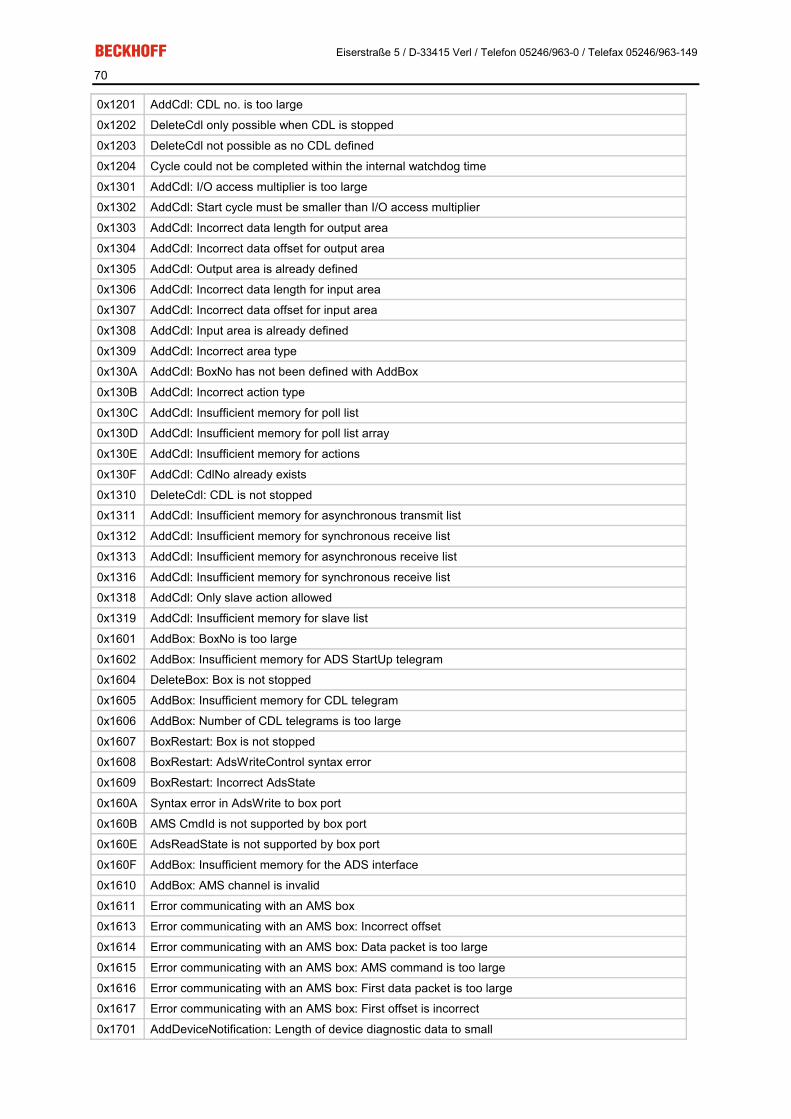
Eiserstraße 5 / D-33415 Verl / Telefon 05246/963-0 / Telefax 05246/963-149
70
0x1201 AddCdl: CDL no. is too large
0x1202 DeleteCdl only possible when CDL is stopped
0x1203 DeleteCdl not possible as no CDL defined
0x1204 Cycle could not be completed within the internal watchdog time
0x1301 AddCdl: I/O access multiplier is too large
0x1302 AddCdl: Start cycle must be smaller than I/O access multiplier
0x1303 AddCdl: Incorrect data length for output area
0x1304 AddCdl: Incorrect data offset for output area
0x1305 AddCdl: Output area is already defined
0x1306 AddCdl: Incorrect data length for input area
0x1307 AddCdl: Incorrect data offset for input area
0x1308 AddCdl: Input area is already defined
0x1309 AddCdl: Incorrect area type
0x130A AddCdl: BoxNo has not been defined with AddBox
0x130B AddCdl: Incorrect action type
0x130C AddCdl: Insufficient memory for poll list
0x130D AddCdl: Insufficient memory for poll list array
0x130E AddCdl: Insufficient memory for actions
0x130F AddCdl: CdlNo already exists
0x1310 DeleteCdl: CDL is not stopped
0x1311 AddCdl: Insufficient memory for asynchronous transmit list
0x1312 AddCdl: Insufficient memory for synchronous receive list
0x1313 AddCdl: Insufficient memory for asynchronous receive list
0x1316 AddCdl: Insufficient memory for synchronous receive list
0x1318 AddCdl: Only slave action allowed
0x1319 AddCdl: Insufficient memory for slave list
0x1601 AddBox: BoxNo is too large
0x1602 AddBox: Insufficient memory for ADS StartUp telegram
0x1604 DeleteBox: Box is not stopped
0x1605 AddBox: Insufficient memory for CDL telegram
0x1606 AddBox: Number of CDL telegrams is too large
0x1607 BoxRestart: Box is not stopped
0x1608 BoxRestart: AdsWriteControl syntax error
0x1609 BoxRestart: Incorrect AdsState
0x160A Syntax error in AdsWrite to box port
0x160B AMS CmdId is not supported by box port
0x160E AdsReadState is not supported by box port
0x160F AddBox: Insufficient memory for the ADS interface
0x1610 AddBox: AMS channel is invalid
0x1611 Error communicating with an AMS box
0x1613 Error communicating with an AMS box: Incorrect offset
0x1614 Error communicating with an AMS box: Data packet is too large
0x1615 Error communicating with an AMS box: AMS command is too large
0x1616 Error communicating with an AMS box: First data packet is too large
0x1617 Error communicating with an AMS box: First offset is incorrect
0x1701 AddDeviceNotification: Length of device diagnostic data to small

Eiserstraße 5 / D-33415 Verl / Telefon 05246/963-0 / Telefax 05246/963-149
71
0x1702 AddDeviceNotification: Length of device diagnostic data to large
0x1703 AddDeviceNotification: Length of box diagnostic data to small
0x1704 AddDeviceNotification: Length of box diagnostic data to large
0x1705 AddDeviceNotification: Box is not defined
0x1706 AddDeviceNotification: Incorrect IndexGroup
0x1707 AddDeviceNotification: No more resources for client
0x1708 DelDeviceNotification: Incorrect handle
0x1801 StartFieldbus: In equidistant operation, shift time + safety time + 2*PLL sync. time must be greater than the cycle time
0x1802 StartFieldbus: Cycle time is too large
0x1803 StartFieldbus: Cycle time is too large
0x1804 StartFieldbus: Shift time is too large
0x1805 StartFieldbus: PLL sync time is too large
0x1806 StartFieldbus: Safety time is too large
0x1807 StartFieldbus: Cycle times shorter than 1 ms must be integral divisors of 1 ms
0x1A01 Memory could not be allocated from the huge heap, because it is larger than 0x8000 bytes
0x1A02 Memory could not be allocated from the near heap, because it is larger than 0x1000 bytes
0x1A03 Memory could not be allocated from the huge heap, because it is 0 bytes
0x1A04 Memory could not be allocated from the near heap, because it is 0 bytes
0x2001 StartFieldbus: Initialisation of the CAN controller failed
0x2002 AddBox: Incorrect box parameter length
0x2003 AddBox: Incorrect box number
0x2004 AddBox: Syntax error in ADS StartUp parameters
0x2005 AddBox: Syntax errors in PDO parameters
0x2006 AddBox: Syntax error in data length
0x2007 AddBox: Insufficient memory
0x2008 AddCdl: Incorrect receive data length
0x2009 AddCdl: Incorrect transmit data length
0x200A AddCdl: PDO is not defined
0x200B AddCdl: PDO Id is already defined
0x200C AddBox: Syntax error in ADS StartUp parameters
0x200D AddBox: Syntax error in ADS StartUp parameters
0x200E AddBox: Emergency Id is already defined
0x200F AddBox: Too many PDOs defined
0x2010 AddCdl: Incorrect telegram index
0x2011 AddBox: Too many Rx or Tx PDOs
0x2012 AdsRead: Incorrect IndexGroup
0x2013 AdsRead: Incorrect IndexOffset
0x2014 AdsRead: Incorrect length
0x2015 AdsWrite: Incorrect IndexGroup
0x2016 AdsWrite: Incorrect IndexOffset
0x2017 AdsWrite: Incorrect length
0x2018 AddBox: Guarding time smaller than 10 is not possible
0x2019 AddBox: Incorrect transmission type in CAN Layer 2 node
0x201A AdsRead: not possible at CAN Layer 2 node
0x201B AdsWrite: not possible at CAN Layer 2 node
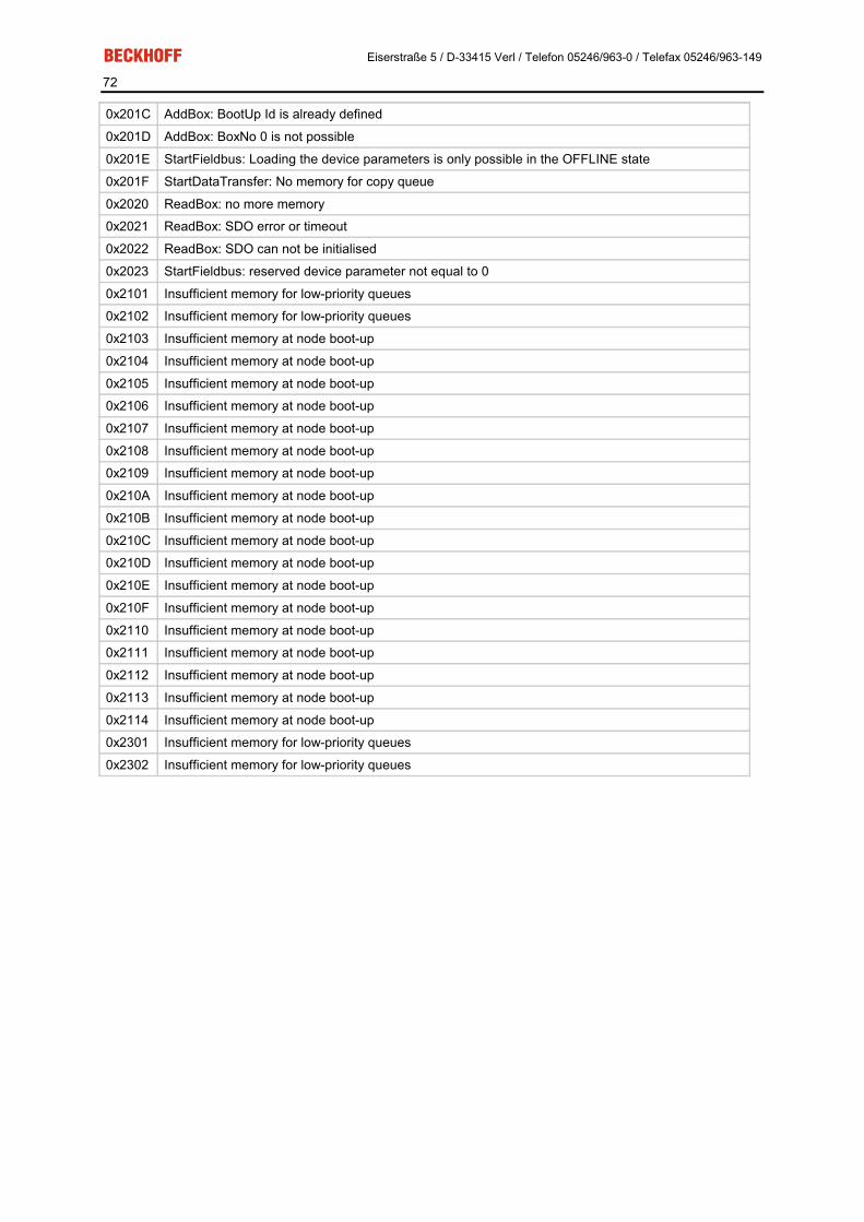
Eiserstraße 5 / D-33415 Verl / Telefon 05246/963-0 / Telefax 05246/963-149
72
0x201C AddBox: BootUp Id is already defined
0x201D AddBox: BoxNo 0 is not possible
0x201E StartFieldbus: Loading the device parameters is only possible in the OFFLINE state
0x201F StartDataTransfer: No memory for copy queue
0x2020 ReadBox: no more memory
0x2021 ReadBox: SDO error or timeout
0x2022 ReadBox: SDO can not be initialised
0x2023 StartFieldbus: reserved device parameter not equal to 0
0x2101 Insufficient memory for low-priority queues
0x2102 Insufficient memory for low-priority queues
0x2103 Insufficient memory at node boot-up
0x2104 Insufficient memory at node boot-up
0x2105 Insufficient memory at node boot-up
0x2106 Insufficient memory at node boot-up
0x2107 Insufficient memory at node boot-up
0x2108 Insufficient memory at node boot-up
0x2109 Insufficient memory at node boot-up
0x210A Insufficient memory at node boot-up
0x210B Insufficient memory at node boot-up
0x210C Insufficient memory at node boot-up
0x210D Insufficient memory at node boot-up
0x210E Insufficient memory at node boot-up
0x210F Insufficient memory at node boot-up
0x2110 Insufficient memory at node boot-up
0x2111 Insufficient memory at node boot-up
0x2112 Insufficient memory at node boot-up
0x2113 Insufficient memory at node boot-up
0x2114 Insufficient memory at node boot-up
0x2301 Insufficient memory for low-priority queues
0x2302 Insufficient memory for low-priority queues

Eiserstraße 5 / D-33415 Verl / Telefon 05246/963-0 / Telefax 05246/963-149
73
Trouble Shooting
Error Frames One sign of errors in the CAN wiring, the address assignment or the setting of the baud rate is an increased number of error frames: the diagnostic LEDs then show Warning Limit exceeded or Bus-off state entered.
Warning
Warning limit exceeded, passive error or bus-off state are indicated first of all at those nodes that have detected the most errors. These nodes are not necessarily the cause for the occurrence of error frames! If, for instance, one node contributes unusually heavily to the bus traffic (perhaps because it is the only one with analog inputs, the data for which triggers event-driven PDOs at a high rate), then the probability of its telegrams being damaged increases. Its error counter will, correspondingly, be the first to reach a critical level.
Node ID / Setting the Baud Rate Care must be taken to ensure that node addresses are not assigned twice: there may only be one sender for each CAN data telegram.
Test 1: Check node addresses. If the CAN communication functions at least some of the time, and if all the devices support the boot up message, then the address assignment can also be examined by recording the boot up messages after the devices are switched on. This will not, however, recognise node addresses that have been swapped.
Test 2: Check that the same baud rate has been set everywhere. For special devices, if the bit timing parameters are accessible, do they agree with the CANopen definitions (sampling time, SJW, oscillator).
Testing the CAN wiring Do not carry out these tests when the network is active - communication should not take place during the tests. The following tests should be carried out in the stated sequence, because some of the tests assume that the previous test was successful. Not all the tests are generally necessary.
Network terminator and signal leads The nodes should be switched off or the CAN cable unplugged for this test, because the results of the meas-urements can otherwise be distorted by the active CAN transceiver.

Eiserstraße 5 / D-33415 Verl / Telefon 05246/963-0 / Telefax 05246/963-149
74
Test 3: Determine the resistance between CAN high and CAN low - at each device, if necessary.
If the measured value is greater than 65 Ohms, it indicates the absence of a terminating resistor or a break in a signal lead. If the measured value is less than 50 Ohms, look for a short circuit between the CAN lines, more than the correct number of terminating resistors, or faulty transceivers.
Test 4: Check for a short circuit between the CAN ground and the signal leads, or between the screen and signal leads.
Test 5: Remove the earth connection from the CAN ground and screen. Check for a short circuit between the CAN ground and screen.
Topology The possible cable length in CAN networks depends heavily on the selected baud rate. CAN will tolerate short drop lines - although this again depends on the baud rate. The maximum permitted length of drop lines should not be exceeded. The length of cable that has been installed is often underestimated - estimates can even be a factor of 10 less than the actual length. The following test is therefore recommended:
Test 6: Measure the lengths of the drop lines and the total bus lengths (do not just make rough estimates!) and com-pare them with the topology rules for the relevant baud rate.
Screening and earthing The power supply and the screen should be carefully earthed at the power supply unit, once only and with low resistance. At all connecting points, branches and so forth the screen of the CAN cable (and possibly the CAN GND) must also be connected, as well as the signal leads. In the Beckhoff IP20 Bus Couplers, the screen is grounded for high frequencies via an R/C element.
Test 7: Use a DC ammeter (16 amp max.) to measure the current between the power supply ground and the screen at the end of the network most remote from the power supply unit. An equalisation current should be present. If there is no current, then either the screen is not connected all the way through, or the power supply unit is not properly earthed. If the power supply unit is somewhere in the middle of the network, the measurement should be performed at both ends. When appropriate, this test can also be carried out at the ends of the drop lines.
Test 8: Interrupt the screen at a number of locations and measure the connection current. If current is flowing, the screen is earthed at more than one place, creating a ground loop.
Potential differences The screen must be connected all the way through for this test, and must not be carrying any current - this has previously been tested.
Test 9: Measure and record the voltage between the screen and the power supply ground at each node. The maximum potential difference between any two devices should be less than 5 volts.
Detect and localise faults The "low-tech approach" usually works best: disconnect parts of the network, and observe when the fault dis-appears.
However, this does not work well for problems such as excessive potential differences, ground loops, EMC or signal distortion, since the reduction in the size of the network often solves the problem without the "missing" piece being the cause. The bus loading also changes as the network is reduced in size, which can mean that external interference "hits" CAN telegrams less often.
Diagnosis with an oscilloscope is not usually successful: even when they are in good condition, CAN signals can look really chaotic. It may be possible to trigger on error frames using a storage oscilloscope - this type of diagnosis, however, is only possible for expert technicians.
Protocol problems In rare cases, protocol problems (such as faulty or incomplete CANopen implementation, unfavourable timing at boot up etc.) can be the cause of faults. In this case it is necessary to trace the bus traffic for evaluation by a CANopen experts - the Beckhoff support team can help here. A free channel on a Beckhoff FC5102 CANopen PCI card is appropriate for such a trace - Beckhoff make the necessary trace software available on the internet. Alternatively, it is of course possible to use a normal com-mercial CAN analysis tool.

Eiserstraße 5 / D-33415 Verl / Telefon 05246/963-0 / Telefax 05246/963-149
75
Protocol problems can be avoided if devices that have not been conformance tested are not used. The official CANopen Conformance Test (and the appropriate certificate) can be obtained from the CAN in Automation association.

Eiserstraße 5 / D-33415 Verl / Telefon 05246/963-0 / Telefax 05246/963-149
76
7. Bus Trace Function Beckhoff FC510x as a CANopen Monitor
As from firmware version 1.00 and TwinCAT 2.8 (Build 738), the FC5101 and FC5102 can be used as CANo-pen monitors instead of masters.
For instance, the second channel of the FC5102 can be used for this purpose, while the first channel continues to function as a CANopen master, or vice versa. In such a case, both channels must be connected to the same CAN network. (Data exchange within the card is not provided, since this cannot take place without interactions.)
The telegrams recorded by the FC510x are temporarily stored in a ring buffer by the task linked with the FC510x; the stored telegrams can then be accessed by ADS. There is a CANopen monitor program (CAN-MON) offering filter and trigger facilities available as freeware from Beckhoff. The user's own applications may also access the monitor data using the ADS interface described below.
Inserting the FC510x as a CANopen Monitor In the Insert device context menu: insert CANopen monitor
After this it is necessary to select the appropriate channel (PCI memory address).
Linking the FC510x with a task The monitor data is accessed at the start of a task from real-time TwinCAT. For this purpose it is necessary to create an additional task in the system manager, containing at least one UINT16 input variable that is to be linked to one of the variables in the FC510x.
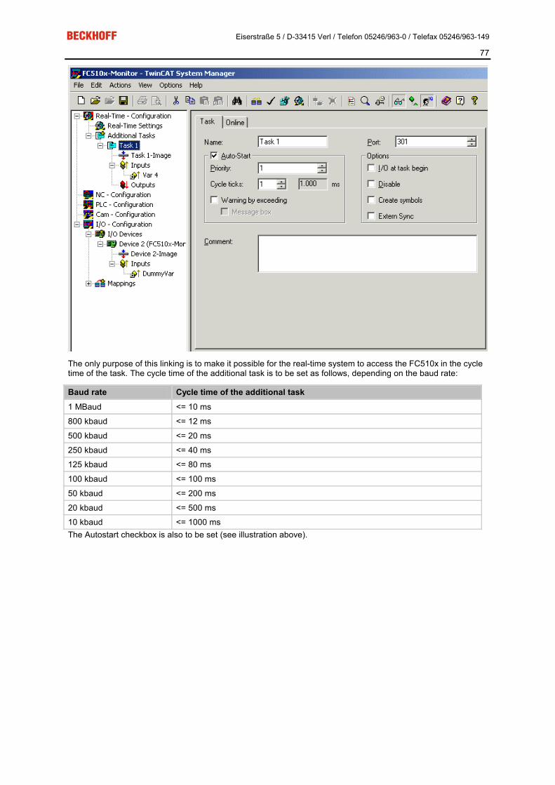
Eiserstraße 5 / D-33415 Verl / Telefon 05246/963-0 / Telefax 05246/963-149
77
The only purpose of this linking is to make it possible for the real-time system to access the FC510x in the cycle time of the task. The cycle time of the additional task is to be set as follows, depending on the baud rate:
Baud rate Cycle time of the additional task 1 MBaud <= 10 ms
800 kbaud <= 12 ms
500 kbaud <= 20 ms
250 kbaud <= 40 ms
125 kbaud <= 80 ms
100 kbaud <= 100 ms
50 kbaud <= 200 ms
20 kbaud <= 500 ms
10 kbaud <= 1000 ms The Autostart checkbox is also to be set (see illustration above).

Eiserstraße 5 / D-33415 Verl / Telefon 05246/963-0 / Telefax 05246/963-149
78
"FCxxxx Monitor" tab
PCI Slot/Irq: Indicates in which logical PCI slot the card was found.
Search...: Searches for all connected FC510x channels. Select those desired. In the case of an FC5102 both channels A and B appear. These behave in logical terms like two FC5101 cards.
Hardware Configuration...: The hardware version number of the FC510x can be displayed here.
Firmware: Shows the current firmware version of the FC510x.
Firmware Update...: Update the FC510x card firmware version here.
Baudrate: The CAN baud rate is set here.
Ring buffer: The size of the ring buffer is set here. The recording time for the ring buffer size that has been set when the bus is fully loaded is also given.
Autostart: If the Autostart checkbox is ticked, the monitor recording can be started when TwinCAT starts. Oth-erwise the monitor software must be used to start it via ADS.
Monitor Software The monitor software fetches the trace data from the FC510x card and places it as a file in the desired mass storage. Only the DLL (TcRouterHelper.dll) is required in addition to the monitor programme itself (CAN-Monitor.exe). This must be placed in the same directory as the monitor program.
After starting the monitor program, the device ID of the FC5101 channel that will be used for the monitoring must be selected.
The following window opens:

Eiserstraße 5 / D-33415 Verl / Telefon 05246/963-0 / Telefax 05246/963-149
79
Device-ID: The ID that the system manager has assigned to the FC510x monitor channel must be entered here:
Storing: The size of the ring buffer memory for the screen display (Display) and for that data output (File) can be set here.
Display: A filter for the display output can be specified here.
Trigger: Trigger conditions that will stop the measurement can be specified here. It is possible, for instance, for a specific otherwise unused output to be set when an error occurs, and to trigger off this bit in the output mod-ule's RxPDO.
Post Trigger: This can be used to specify how many telegrams are still to be recorded after the trigger condi-tion has occurred. The number of telegrams recorded prior to occurrence of the trigger condition is only re-stricted by the specified buffer size.
Trigger and display filters function in such a way that only those bits for which the mask is set to 1 are considered when selecting the identifier (ID) or the data bytes (Data). These bits are then che-cked for conformity with the values specified in Value. The default setting (mask ID = 0x7FF and mask data = 0x00) is relevant if the identifier (ID) specified in Value is to be recognised, regardless of the data. If an identifier (ID) larger than 0x7FF (e.g. 0x800, default) is entered, the filter or trigger is disabled. Example:
The recording is to be stopped after 250 telegrams, after bit 0 in the second data byte of a telegram with identi-

Eiserstraße 5 / D-33415 Verl / Telefon 05246/963-0 / Telefax 05246/963-149
80
fier 0x210 equal to 1 has been found. The following entries are to be made to achieve this:
Starting the Recording TwinCAT must be started, and a variable in a cyclic task (such as the Autostart task) must be linked with the dummy variable of the FC510x in monitoring mode. The recording can now be started by clicking the green traffic light symbol.
If the start-up procedure associated with another CANopen channel in the system is to be recorded, then the "Autostart" checkbox on the System Manager's FC monitor tab is to be selected. The card can then buffer up to 25,000 CAN messages. It is then only necessary to start the recording via monitor software before the CAN card's buffer overflows.
Stopping the Recording Click the red traffic light symbol to stop the recording. The following dialog box opens:
Two trace files are created automatically. One is an ASCII file with the ending *.mon, readable by any text edi-tor. A file with the ending *.ASC is also created: this can be read for further processing by the CANalyzer® tool from Vector Informatik.
Trace example: The beginning of a CANopen boot up with two nodes (node ID 1 and node ID 50) is illustrated.
Number Time(100 µs) Telegram 0 0.0638 Id: 000 Len: 2 Data: 82 00 1 0.0649 Id: 632 Len: 8 Data: 40 00 10 00 00 00 00 00 2 0.0653 Id: 601 Len: 8 Data: 40 00 10 00 00 00 00 00 3 2.0722 Id: 632 Len: 8 Data: 80 00 00 00 00 00 04 05 4 2.0725 Id: 601 Len: 8 Data: 80 00 00 00 00 00 04 05 5 2.2686 Id: 732 Len: 1 Data: 00

Eiserstraße 5 / D-33415 Verl / Telefon 05246/963-0 / Telefax 05246/963-149
81
6 2.7440 Id: 701 Len: 1 Data: 00 7 4.0802 Id: 632 Len: 8 Data: 40 00 10 00 00 00 00 00 8 4.0806 Id: 601 Len: 8 Data: 40 00 10 00 00 00 00 00 9 4.0813 Id: 5b2 Len: 8 Data: 43 00 10 00 91 01 02 00 10 4.0823 Id: 632 Len: 8 Data: 40 18 10 01 00 00 00 00 11 4.0826 Id: 581 Len: 8 Data: 43 00 10 00 91 01 07 00 12 4.0835 Id: 601 Len: 8 Data: 40 18 10 01 00 00 00 00 13 4.0838 Id: 5b2 Len: 8 Data: 43 18 10 01 02 00 00 00 14 4.0848 Id: 632 Len: 8 Data: 23 00 14 01 32 02 00 00 15 4.0853 Id: 581 Len: 8 Data: 43 18 10 01 02 00 00 00 16 4.0863 Id: 601 Len: 8 Data: 23 00 18 01 81 01 00 00
FC510x Monitor ADS Interface The ADS interface for the FC510x monitor is described below.
Starting the Recording Monitor recording is started with the following ADS write command:
NET-ID: PC AMS net ID.
PORT: 300
IDXGRP: IndexGroup is 0x5000 + Id (on the "General" tab for the FC510x monitor) of the FC510x monitor
IDXOFFS: IndexOffset is 0xFFFF1000
LEN: Data length is 2
DATA: A word with the value 1 is to be transmitted
Stopping the Recording Monitor recording is stopped with the following ADS write command:
NET-ID: PC AMS net ID.
PORT: 300
IDXGRP: IndexGroup is 0x5000 + Id (on the General tab for the FC510x monitor) of the FC510x monitor
IDXOFFS: IndexOffset is 0xFFFF1000
LEN: Data length is 2
DATA: A word with the value 0 is to be transmitted
Structure of the Ring Buffer The ring buffer in which the recorded telegrams are stored is divided into 4 kbyte pages. Each page has the following structure:
Offset Description 0x0000 - 0x0FEF Recorded telegrams (see below)
0x0FF0 - 0x0FF3 reserved
0x0FF4 - 0x0FF7 Length of the data actually read (only in the first read page)
0x0FF8 - 0x0FF9 1: Further pages are stored, 0: no further pages are stored
0x0FFA - 0x0FFB reserved
0x0FFC - 0x0FFD End of the telegrams recorded on this page (points to the first memory location following the last telegram)
0x0FFE - 0x0FFF Page number
Reading the Recorded Telegrams The monitor telegrams that have been recorded can be read with the following ADS read command:

Eiserstraße 5 / D-33415 Verl / Telefon 05246/963-0 / Telefax 05246/963-149
82
NET-ID: PC AMS net ID.
PORT: 300
IDXGRP: IndexGroup is 0x5000 + Id (on the General tab for the FC510x monitor) of the FC510x monitor
IDXOFFS: IndexOffset is 0xFFFF0000 - 0xFFFF1FFF (bits 0-11: number of the first page to be read, bit 12 = 0: only read full pages, bit 12 = 1: also read the last, incomplete, page if appropriate)
LEN: 0x1000 (1 page), 0x2000 (2 pages), 0x3000 (3 pages) or 0x4000 (4 pages) are permitted as the data length
DATA: The corresponding pages are returned
Telegram Structure The recorded telegrams have the following structure:
Offset Description 0-2 Time stamp in 8/25 µs
3 0x00: Telegram, 0xFF: Error
4 COB-ID, Hi-Byte
5 COB-ID, Lo-Byte
6-13 The telegram's data
Eiserstraße 5 / D-33415 Verl / Telefon 05246/963-0 / Telefax 05246/963-149
83
8. Appendix Identifier Full List
Identifiers marked with * are given manufacturer-specific assignments on the bus couplers after writing index 0x5500
dez hex Meaning dez hex Meaning dez hex Meaning 0 0 NMT 874 36A RxPDO7*, Nd.42 1430 596 SDO Tx Nd.22
128 80 SYNC 875 36B RxPDO7*, Nd.43 1431 597 SDO Tx Nd.23
129 81 EMCY Nd.1 876 36C RxPDO7*, Nd.44 1432 598 SDO Tx Nd.24
130 82 EMCY Nd.2 877 36D RxPDO7*, Nd.45 1433 599 SDO Tx Nd.25
131 83 EMCY Nd.3 878 36E RxPDO7*, Nd.46 1434 59A SDO Tx Nd.26
132 84 EMCY Nd.4 879 36F RxPDO7*, Nd.47 1435 59B SDO Tx Nd.27
133 85 EMCY Nd.5 880 370 RxPDO7*, Nd.48 1436 59C SDO Tx Nd.28
134 86 EMCY Nd.6 881 371 RxPDO7*, Nd.49 1437 59D SDO Tx Nd.29
135 87 EMCY Nd.7 882 372 RxPDO7*, Nd.50 1438 59E SDO Tx Nd.30
136 88 EMCY Nd.8 883 373 RxPDO7*, Nd.51 1439 59F SDO Tx Nd.31
137 89 EMCY Nd.9 884 374 RxPDO7*, Nd.52 1440 5A0 SDO Tx Nd.32
138 8A EMCY Nd.10 885 375 RxPDO7*, Nd.53 1441 5A1 SDO Tx Nd.33
139 8B EMCY Nd.11 886 376 RxPDO7*, Nd.54 1442 5A2 SDO Tx Nd.34
140 8C EMCY Nd.12 887 377 RxPDO7*, Nd.55 1443 5A3 SDO Tx Nd.35
141 8D EMCY Nd.13 888 378 RxPDO7*, Nd.56 1444 5A4 SDO Tx Nd.36
142 8E EMCY Nd.14 889 379 RxPDO7*, Nd.57 1445 5A5 SDO Tx Nd.37
143 8F EMCY Nd.15 890 37A RxPDO7*, Nd.58 1446 5A6 SDO Tx Nd.38
144 90 EMCY Nd.16 891 37B RxPDO7*, Nd.59 1447 5A7 SDO Tx Nd.39
145 91 EMCY Nd.17 892 37C RxPDO7*, Nd.60 1448 5A8 SDO Tx Nd.40
146 92 EMCY Nd.18 893 37D RxPDO7*, Nd.61 1449 5A9 SDO Tx Nd.41
147 93 EMCY Nd.19 894 37E RxPDO7*, Nd.62 1450 5AA SDO Tx Nd.42
148 94 EMCY Nd.20 895 37F RxPDO7*, Nd.63 1451 5AB SDO Tx Nd.43
149 95 EMCY Nd.21 897 381 TxPDO3*, Nd.1 1452 5AC SDO Tx Nd.44
150 96 EMCY Nd.22 898 382 TxPDO3*, Nd.2 1453 5AD SDO Tx Nd.45
151 97 EMCY Nd.23 899 383 TxPDO3*, Nd.3 1454 5AE SDO Tx Nd.46
152 98 EMCY Nd.24 900 384 TxPDO3*, Nd.4 1455 5AF SDO Tx Nd.47
153 99 EMCY Nd.25 901 385 TxPDO3*, Nd.5 1456 5B0 SDO Tx Nd.48
154 9A EMCY Nd.26 902 386 TxPDO3*, Nd.6 1457 5B1 SDO Tx Nd.49
155 9B EMCY Nd.27 903 387 TxPDO3*, Nd.7 1458 5B2 SDO Tx Nd.50
156 9C EMCY Nd.28 904 388 TxPDO3*, Nd.8 1459 5B3 SDO Tx Nd.51
157 9D EMCY Nd.29 905 389 TxPDO3*, Nd.9 1460 5B4 SDO Tx Nd.52
158 9E EMCY Nd.30 906 38A TxPDO3*, Nd.10 1461 5B5 SDO Tx Nd.53
159 9F EMCY Nd.31 907 38B TxPDO3*, Nd.11 1462 5B6 SDO Tx Nd.54
160 A0 EMCY Nd.32 908 38C TxPDO3*, Nd.12 1463 5B7 SDO Tx Nd.55
161 A1 EMCY Nd.33 909 38D TxPDO3*, Nd.13 1464 5B8 SDO Tx Nd.56
162 A2 EMCY Nd.34 910 38E TxPDO3*, Nd.14 1465 5B9 SDO Tx Nd.57
163 A3 EMCY Nd.35 911 38F TxPDO3*, Nd.15 1466 5BA SDO Tx Nd.58
164 A4 EMCY Nd.36 912 390 TxPDO3*, Nd.16 1467 5BB SDO Tx Nd.59
165 A5 EMCY Nd.37 913 391 TxPDO3*, Nd.17 1468 5BC SDO Tx Nd.60
Eiserstraße 5 / D-33415 Verl / Telefon 05246/963-0 / Telefax 05246/963-149
84
166 A6 EMCY Nd.38 914 392 TxPDO3*, Nd.18 1469 5BD SDO Tx Nd.61
167 A7 EMCY Nd.39 915 393 TxPDO3*, Nd.19 1470 5BE SDO Tx Nd.62
168 A8 EMCY Nd.40 916 394 TxPDO3*, Nd.20 1471 5BF SDO Tx Nd.63
169 A9 EMCY Nd.41 917 395 TxPDO3*, Nd.21 1473 5C1 TxPDO10*, Nd.1
170 AA EMCY Nd.42 918 396 TxPDO3*, Nd.22 1474 5C2 TxPDO10*, Nd.2
171 AB EMCY Nd.43 919 397 TxPDO3*, Nd.23 1475 5C3 TxPDO10*, Nd.3
172 AC EMCY Nd.44 920 398 TxPDO3*, Nd.24 1476 5C4 TxPDO10*, Nd.4
173 AD EMCY Nd.45 921 399 TxPDO3*, Nd.25 1477 5C5 TxPDO10*, Nd.5
174 AE EMCY Nd.46 922 39A TxPDO3*, Nd.26 1478 5C6 TxPDO10*, Nd.6
175 AF EMCY Nd.47 923 39B TxPDO3*, Nd.27 1479 5C7 TxPDO10*, Nd.7
176 B0 EMCY Nd.48 924 39C TxPDO3*, Nd.28 1480 5C8 TxPDO10*, Nd.8
177 B1 EMCY Nd.49 925 39D TxPDO3*, Nd.29 1481 5C9 TxPDO10*, Nd.9
178 B2 EMCY Nd.50 926 39E TxPDO3*, Nd.30 1482 5CA TxPDO10*, Nd.10
179 B3 EMCY Nd.51 927 39F TxPDO3*, Nd.31 1483 5CB TxPDO10*, Nd.11
180 B4 EMCY Nd.52 928 3A0 TxPDO3*, Nd.32 1484 5CC TxPDO10*, Nd.12
181 B5 EMCY Nd.53 929 3A1 TxPDO3*, Nd.33 1485 5CD TxPDO10*, Nd.13
182 B6 EMCY Nd.54 930 3A2 TxPDO3*, Nd.34 1486 5CE TxPDO10*, Nd.14
183 B7 EMCY Nd.55 931 3A3 TxPDO3*, Nd.35 1487 5CF TxPDO10*, Nd.15
184 B8 EMCY Nd.56 932 3A4 TxPDO3*, Nd.36 1488 5D0 TxPDO10*, Nd.16
185 B9 EMCY Nd.57 933 3A5 TxPDO3*, Nd.37 1489 5D1 TxPDO10*, Nd.17
186 BA EMCY Nd.58 934 3A6 TxPDO3*, Nd.38 1490 5D2 TxPDO10*, Nd.18
187 BB EMCY Nd.59 935 3A7 TxPDO3*, Nd.39 1491 5D3 TxPDO10*, Nd.19
188 BC EMCY Nd.60 936 3A8 TxPDO3*, Nd.40 1492 5D4 TxPDO10*, Nd.20
189 BD EMCY Nd.61 937 3A9 TxPDO3*, Nd.41 1493 5D5 TxPDO10*, Nd.21
190 BE EMCY Nd.62 938 3AA TxPDO3*, Nd.42 1494 5D6 TxPDO10*, Nd.22
191 BF EMCY Nd.63 939 3AB TxPDO3*, Nd.43 1495 5D7 TxPDO10*, Nd.23
385 181 TxPDO1, DI, Nd.1 940 3AC TxPDO3*, Nd.44 1496 5D8 TxPDO10*, Nd.24
386 182 TxPDO1, DI, Nd.2 941 3AD TxPDO3*, Nd.45 1497 5D9 TxPDO10*, Nd.25
387 183 TxPDO1, DI, Nd.3 942 3AE TxPDO3*, Nd.46 1498 5DA TxPDO10*, Nd.26
388 184 TxPDO1, DI, Nd.4 943 3AF TxPDO3*, Nd.47 1499 5DB TxPDO10*, Nd.27
389 185 TxPDO1, DI, Nd.5 944 3B0 TxPDO3*, Nd.48 1500 5DC TxPDO10*, Nd.28
390 186 TxPDO1, DI, Nd.6 945 3B1 TxPDO3*, Nd.49 1501 5DD TxPDO10*, Nd.29
391 187 TxPDO1, DI, Nd.7 946 3B2 TxPDO3*, Nd.50 1502 5DE TxPDO10*, Nd.30
392 188 TxPDO1, DI, Nd.8 947 3B3 TxPDO3*, Nd.51 1503 5DF TxPDO10*, Nd.31
393 189 TxPDO1, DI, Nd.9 948 3B4 TxPDO3*, Nd.52 1504 5E0 TxPDO10*, Nd.32
394 18A TxPDO1, DI, Nd.10 949 3B5 TxPDO3*, Nd.53 1505 5E1 TxPDO10*, Nd.33
395 18B TxPDO1, DI, Nd.11 950 3B6 TxPDO3*, Nd.54 1506 5E2 TxPDO10*, Nd.34
396 18C TxPDO1, DI, Nd.12 951 3B7 TxPDO3*, Nd.55 1507 5E3 TxPDO10*, Nd.35
397 18D TxPDO1, DI, Nd.13 952 3B8 TxPDO3*, Nd.56 1508 5E4 TxPDO10*, Nd.36
398 18E TxPDO1, DI, Nd.14 953 3B9 TxPDO3*, Nd.57 1509 5E5 TxPDO10*, Nd.37
399 18F TxPDO1, DI, Nd.15 954 3BA TxPDO3*, Nd.58 1510 5E6 TxPDO10*, Nd.38
400 190 TxPDO1, DI, Nd.16 955 3BB TxPDO3*, Nd.59 1511 5E7 TxPDO10*, Nd.39
401 191 TxPDO1, DI, Nd.17 956 3BC TxPDO3*, Nd.60 1512 5E8 TxPDO10*, Nd.40
402 192 TxPDO1, DI, Nd.18 957 3BD TxPDO3*, Nd.61 1513 5E9 TxPDO10*, Nd.41
403 193 TxPDO1, DI, Nd.19 958 3BE TxPDO3*, Nd.62 1514 5EA TxPDO10*, Nd.42
404 194 TxPDO1, DI, Nd.20 959 3BF TxPDO3*, Nd.63 1515 5EB TxPDO10*, Nd.43

Eiserstraße 5 / D-33415 Verl / Telefon 05246/963-0 / Telefax 05246/963-149
85
405 195 TxPDO1, DI, Nd.21 961 3C1 TxPDO8*, Nd.1 1516 5EC TxPDO10*, Nd.44
406 196 TxPDO1, DI, Nd.22 962 3C2 TxPDO8*, Nd.2 1517 5ED TxPDO10*, Nd.45
407 197 TxPDO1, DI, Nd.23 963 3C3 TxPDO8*, Nd.3 1518 5EE TxPDO10*, Nd.46
408 198 TxPDO1, DI, Nd.24 964 3C4 TxPDO8*, Nd.4 1519 5EF TxPDO10*, Nd.47
409 199 TxPDO1, DI, Nd.25 965 3C5 TxPDO8*, Nd.5 1520 5F0 TxPDO10*, Nd.48
410 19A TxPDO1, DI, Nd.26 966 3C6 TxPDO8*, Nd.6 1521 5F1 TxPDO10*, Nd.49
411 19B TxPDO1, DI, Nd.27 967 3C7 TxPDO8*, Nd.7 1522 5F2 TxPDO10*, Nd.50
412 19C TxPDO1, DI, Nd.28 968 3C8 TxPDO8*, Nd.8 1523 5F3 TxPDO10*, Nd.51
413 19D TxPDO1, DI, Nd.29 969 3C9 TxPDO8*, Nd.9 1524 5F4 TxPDO10*, Nd.52
414 19E TxPDO1, DI, Nd.30 970 3CA TxPDO8*, Nd.10 1525 5F5 TxPDO10*, Nd.53
415 19F TxPDO1, DI, Nd.31 971 3CB TxPDO8*, Nd.11 1526 5F6 TxPDO10*, Nd.54
416 1A0 TxPDO1, DI, Nd.32 972 3CC TxPDO8*, Nd.12 1527 5F7 TxPDO10*, Nd.55
417 1A1 TxPDO1, DI, Nd.33 973 3CD TxPDO8*, Nd.13 1528 5F8 TxPDO10*, Nd.56
418 1A2 TxPDO1, DI, Nd.34 974 3CE TxPDO8*, Nd.14 1529 5F9 TxPDO10*, Nd.57
419 1A3 TxPDO1, DI, Nd.35 975 3CF TxPDO8*, Nd.15 1530 5FA TxPDO10*, Nd.58
420 1A4 TxPDO1, DI, Nd.36 976 3D0 TxPDO8*, Nd.16 1531 5FB TxPDO10*, Nd.59
421 1A5 TxPDO1, DI, Nd.37 977 3D1 TxPDO8*, Nd.17 1532 5FC TxPDO10*, Nd.60
422 1A6 TxPDO1, DI, Nd.38 978 3D2 TxPDO8*, Nd.18 1533 5FD TxPDO10*, Nd.61
423 1A7 TxPDO1, DI, Nd.39 979 3D3 TxPDO8*, Nd.19 1534 5FE TxPDO10*, Nd.62
424 1A8 TxPDO1, DI, Nd.40 980 3D4 TxPDO8*, Nd.20 1535 5FF TxPDO10*, Nd.63
425 1A9 TxPDO1, DI, Nd.41 981 3D5 TxPDO8*, Nd.21 1537 601 SDO Rx Nd.1
426 1AA TxPDO1, DI, Nd.42 982 3D6 TxPDO8*, Nd.22 1538 602 SDO Rx Nd.2
427 1AB TxPDO1, DI, Nd.43 983 3D7 TxPDO8*, Nd.23 1539 603 SDO Rx Nd.3
428 1AC TxPDO1, DI, Nd.44 984 3D8 TxPDO8*, Nd.24 1540 604 SDO Rx Nd.4
429 1AD TxPDO1, DI, Nd.45 985 3D9 TxPDO8*, Nd.25 1541 605 SDO Rx Nd.5
430 1AE TxPDO1, DI, Nd.46 986 3DA TxPDO8*, Nd.26 1542 606 SDO Rx Nd.6
431 1AF TxPDO1, DI, Nd.47 987 3DB TxPDO8*, Nd.27 1543 607 SDO Rx Nd.7
432 1B0 TxPDO1, DI, Nd.48 988 3DC TxPDO8*, Nd.28 1544 608 SDO Rx Nd.8
433 1B1 TxPDO1, DI, Nd.49 989 3DD TxPDO8*, Nd.29 1545 609 SDO Rx Nd.9
434 1B2 TxPDO1, DI, Nd.50 990 3DE TxPDO8*, Nd.30 1546 60A SDO Rx Nd.10
435 1B3 TxPDO1, DI, Nd.51 991 3DF TxPDO8*, Nd.31 1547 60B SDO Rx Nd.11
436 1B4 TxPDO1, DI, Nd.52 992 3E0 TxPDO8*, Nd.32 1548 60C SDO Rx Nd.12
437 1B5 TxPDO1, DI, Nd.53 993 3E1 TxPDO8*, Nd.33 1549 60D SDO Rx Nd.13
438 1B6 TxPDO1, DI, Nd.54 994 3E2 TxPDO8*, Nd.34 1550 60E SDO Rx Nd.14
439 1B7 TxPDO1, DI, Nd.55 995 3E3 TxPDO8*, Nd.35 1551 60F SDO Rx Nd.15
440 1B8 TxPDO1, DI, Nd.56 996 3E4 TxPDO8*, Nd.36 1552 610 SDO Rx Nd.16
441 1B9 TxPDO1, DI, Nd.57 997 3E5 TxPDO8*, Nd.37 1553 611 SDO Rx Nd.17
442 1BA TxPDO1, DI, Nd.58 998 3E6 TxPDO8*, Nd.38 1554 612 SDO Rx Nd.18
443 1BB TxPDO1, DI, Nd.59 999 3E7 TxPDO8*, Nd.39 1555 613 SDO Rx Nd.19
444 1BC TxPDO1, DI, Nd.60 1000 3E8 TxPDO8*, Nd.40 1556 614 SDO Rx Nd.20
445 1BD TxPDO1, DI, Nd.61 1001 3E9 TxPDO8*, Nd.41 1557 615 SDO Rx Nd.21
446 1BE TxPDO1, DI, Nd.62 1002 3EA TxPDO8*, Nd.42 1558 616 SDO Rx Nd.22
447 1BF TxPDO1, DI, Nd.63 1003 3EB TxPDO8*, Nd.43 1559 617 SDO Rx Nd.23
449 1C1 TxPDO6*, Nd.1 1004 3EC TxPDO8*, Nd.44 1560 618 SDO Rx Nd.24
450 1C2 TxPDO6*, Nd.2 1005 3ED TxPDO8*, Nd.45 1561 619 SDO Rx Nd.25
451 1C3 TxPDO6*, Nd.3 1006 3EE TxPDO8*, Nd.46 1562 61A SDO Rx Nd.26
Eiserstraße 5 / D-33415 Verl / Telefon 05246/963-0 / Telefax 05246/963-149
86
452 1C4 TxPDO6*, Nd.4 1007 3EF TxPDO8*, Nd.47 1563 61B SDO Rx Nd.27
453 1C5 TxPDO6*, Nd.5 1008 3F0 TxPDO8*, Nd.48 1564 61C SDO Rx Nd.28
454 1C6 TxPDO6*, Nd.6 1009 3F1 TxPDO8*, Nd.49 1565 61D SDO Rx Nd.29
455 1C7 TxPDO6*, Nd.7 1010 3F2 TxPDO8*, Nd.50 1566 61E SDO Rx Nd.30
456 1C8 TxPDO6*, Nd.8 1011 3F3 TxPDO8*, Nd.51 1567 61F SDO Rx Nd.31
457 1C9 TxPDO6*, Nd.9 1012 3F4 TxPDO8*, Nd.52 1568 620 SDO Rx Nd.32
458 1CA TxPDO6*, Nd.10 1013 3F5 TxPDO8*, Nd.53 1569 621 SDO Rx Nd.33
459 1CB TxPDO6*, Nd.11 1014 3F6 TxPDO8*, Nd.54 1570 622 SDO Rx Nd.34
460 1CC TxPDO6*, Nd.12 1015 3F7 TxPDO8*, Nd.55 1571 623 SDO Rx Nd.35
461 1CD TxPDO6*, Nd.13 1016 3F8 TxPDO8*, Nd.56 1572 624 SDO Rx Nd.36
462 1CE TxPDO6*, Nd.14 1017 3F9 TxPDO8*, Nd.57 1573 625 SDO Rx Nd.37
463 1CF TxPDO6*, Nd.15 1018 3FA TxPDO8*, Nd.58 1574 626 SDO Rx Nd.38
464 1D0 TxPDO6*, Nd.16 1019 3FB TxPDO8*, Nd.59 1575 627 SDO Rx Nd.39
465 1D1 TxPDO6*, Nd.17 1020 3FC TxPDO8*, Nd.60 1576 628 SDO Rx Nd.40
466 1D2 TxPDO6*, Nd.18 1021 3FD TxPDO8*, Nd.61 1577 629 SDO Rx Nd.41
467 1D3 TxPDO6*, Nd.19 1022 3FE TxPDO8*, Nd.62 1578 62A SDO Rx Nd.42
468 1D4 TxPDO6*, Nd.20 1023 3FF TxPDO8*, Nd.63 1579 62B SDO Rx Nd.43
469 1D5 TxPDO6*, Nd.21 1025 401 RxPDO3*, Nd.1 1580 62C SDO Rx Nd.44
470 1D6 TxPDO6*, Nd.22 1026 402 RxPDO3*, Nd.2 1581 62D SDO Rx Nd.45
471 1D7 TxPDO6*, Nd.23 1027 403 RxPDO3*, Nd.3 1582 62E SDO Rx Nd.46
472 1D8 TxPDO6*, Nd.24 1028 404 RxPDO3*, Nd.4 1583 62F SDO Rx Nd.47
473 1D9 TxPDO6*, Nd.25 1029 405 RxPDO3*, Nd.5 1584 630 SDO Rx Nd.48
474 1DA TxPDO6*, Nd.26 1030 406 RxPDO3*, Nd.6 1585 631 SDO Rx Nd.49
475 1DB TxPDO6*, Nd.27 1031 407 RxPDO3*, Nd.7 1586 632 SDO Rx Nd.50
476 1DC TxPDO6*, Nd.28 1032 408 RxPDO3*, Nd.8 1587 633 SDO Rx Nd.51
477 1DD TxPDO6*, Nd.29 1033 409 RxPDO3*, Nd.9 1588 634 SDO Rx Nd.52
478 1DE TxPDO6*, Nd.30 1034 40A RxPDO3*, Nd.10 1589 635 SDO Rx Nd.53
479 1DF TxPDO6*, Nd.31 1035 40B RxPDO3*, Nd.11 1590 636 SDO Rx Nd.54
480 1E0 TxPDO6*, Nd.32 1036 40C RxPDO3*, Nd.12 1591 637 SDO Rx Nd.55
481 1E1 TxPDO6*, Nd.33 1037 40D RxPDO3*, Nd.13 1592 638 SDO Rx Nd.56
482 1E2 TxPDO6*, Nd.34 1038 40E RxPDO3*, Nd.14 1593 639 SDO Rx Nd.57
483 1E3 TxPDO6*, Nd.35 1039 40F RxPDO3*, Nd.15 1594 63A SDO Rx Nd.58
484 1E4 TxPDO6*, Nd.36 1040 410 RxPDO3*, Nd.16 1595 63B SDO Rx Nd.59
485 1E5 TxPDO6*, Nd.37 1041 411 RxPDO3*, Nd.17 1596 63C SDO Rx Nd.60
486 1E6 TxPDO6*, Nd.38 1042 412 RxPDO3*, Nd.18 1597 63D SDO Rx Nd.61
487 1E7 TxPDO6*, Nd.39 1043 413 RxPDO3*, Nd.19 1598 63E SDO Rx Nd.62
488 1E8 TxPDO6*, Nd.40 1044 414 RxPDO3*, Nd.20 1599 63F SDO Rx Nd.63
489 1E9 TxPDO6*, Nd.41 1045 415 RxPDO3*, Nd.21 1601 641 RxPDO10*, Nd.1
490 1EA TxPDO6*, Nd.42 1046 416 RxPDO3*, Nd.22 1602 642 RxPDO10*, Nd.2
491 1EB TxPDO6*, Nd.43 1047 417 RxPDO3*, Nd.23 1603 643 RxPDO10*, Nd.3
492 1EC TxPDO6*, Nd.44 1048 418 RxPDO3*, Nd.24 1604 644 RxPDO10*, Nd.4
493 1ED TxPDO6*, Nd.45 1049 419 RxPDO3*, Nd.25 1605 645 RxPDO10*, Nd.5
494 1EE TxPDO6*, Nd.46 1050 41A RxPDO3*, Nd.26 1606 646 RxPDO10*, Nd.6
495 1EF TxPDO6*, Nd.47 1051 41B RxPDO3*, Nd.27 1607 647 RxPDO10*, Nd.7
496 1F0 TxPDO6*, Nd.48 1052 41C RxPDO3*, Nd.28 1608 648 RxPDO10*, Nd.8
497 1F1 TxPDO6*, Nd.49 1053 41D RxPDO3*, Nd.29 1609 649 RxPDO10*, Nd.9
Eiserstraße 5 / D-33415 Verl / Telefon 05246/963-0 / Telefax 05246/963-149
87
498 1F2 TxPDO6*, Nd.50 1054 41E RxPDO3*, Nd.30 1610 64A RxPDO10*, Nd.10
499 1F3 TxPDO6*, Nd.51 1055 41F RxPDO3*, Nd.31 1611 64B RxPDO10*, Nd.11
500 1F4 TxPDO6*, Nd.52 1056 420 RxPDO3*, Nd.32 1612 64C RxPDO10*, Nd.12
501 1F5 TxPDO6*, Nd.53 1057 421 RxPDO3*, Nd.33 1613 64D RxPDO10*, Nd.13
502 1F6 TxPDO6*, Nd.54 1058 422 RxPDO3*, Nd.34 1614 64E RxPDO10*, Nd.14
503 1F7 TxPDO6*, Nd.55 1059 423 RxPDO3*, Nd.35 1615 64F RxPDO10*, Nd.15
504 1F8 TxPDO6*, Nd.56 1060 424 RxPDO3*, Nd.36 1616 650 RxPDO10*, Nd.16
505 1F9 TxPDO6*, Nd.57 1061 425 RxPDO3*, Nd.37 1617 651 RxPDO10*, Nd.17
506 1FA TxPDO6*, Nd.58 1062 426 RxPDO3*, Nd.38 1618 652 RxPDO10*, Nd.18
507 1FB TxPDO6*, Nd.59 1063 427 RxPDO3*, Nd.39 1619 653 RxPDO10*, Nd.19
508 1FC TxPDO6*, Nd.60 1064 428 RxPDO3*, Nd.40 1620 654 RxPDO10*, Nd.20
509 1FD TxPDO6*, Nd.61 1065 429 RxPDO3*, Nd.41 1621 655 RxPDO10*, Nd.21
510 1FE TxPDO6*, Nd.62 1066 42A RxPDO3*, Nd.42 1622 656 RxPDO10*, Nd.22
511 1FF TxPDO6*, Nd.63 1067 42B RxPDO3*, Nd.43 1623 657 RxPDO10*, Nd.23
513 201 RxPDO1, DO, Nd.1 1068 42C RxPDO3*, Nd.44 1624 658 RxPDO10*, Nd.24
514 202 RxPDO1, DO, Nd.2 1069 42D RxPDO3*, Nd.45 1625 659 RxPDO10*, Nd.25
515 203 RxPDO1, DO, Nd.3 1070 42E RxPDO3*, Nd.46 1626 65A RxPDO10*, Nd.26
516 204 RxPDO1, DO, Nd.4 1071 42F RxPDO3*, Nd.47 1627 65B RxPDO10*, Nd.27
517 205 RxPDO1, DO, Nd.5 1072 430 RxPDO3*, Nd.48 1628 65C RxPDO10*, Nd.28
518 206 RxPDO1, DO, Nd.6 1073 431 RxPDO3*, Nd.49 1629 65D RxPDO10*, Nd.29
519 207 RxPDO1, DO, Nd.7 1074 432 RxPDO3*, Nd.50 1630 65E RxPDO10*, Nd.30
520 208 RxPDO1, DO, Nd.8 1075 433 RxPDO3*, Nd.51 1631 65F RxPDO10*, Nd.31
521 209 RxPDO1, DO, Nd.9 1076 434 RxPDO3*, Nd.52 1632 660 RxPDO10*, Nd.32
522 20A RxPDO1, DO, Nd.10 1077 435 RxPDO3*, Nd.53 1633 661 RxPDO10*, Nd.33
523 20B RxPDO1, DO, Nd.11 1078 436 RxPDO3*, Nd.54 1634 662 RxPDO10*, Nd.34
524 20C RxPDO1, DO, Nd.12 1079 437 RxPDO3*, Nd.55 1635 663 RxPDO10*, Nd.35
525 20D RxPDO1, DO, Nd.13 1080 438 RxPDO3*, Nd.56 1636 664 RxPDO10*, Nd.36
526 20E RxPDO1, DO, Nd.14 1081 439 RxPDO3*, Nd.57 1637 665 RxPDO10*, Nd.37
527 20F RxPDO1, DO, Nd.15 1082 43A RxPDO3*, Nd.58 1638 666 RxPDO10*, Nd.38
528 210 RxPDO1, DO, Nd.16 1083 43B RxPDO3*, Nd.59 1639 667 RxPDO10*, Nd.39
529 211 RxPDO1, DO, Nd.17 1084 43C RxPDO3*, Nd.60 1640 668 RxPDO10*, Nd.40
530 212 RxPDO1, DO, Nd.18 1085 43D RxPDO3*, Nd.61 1641 669 RxPDO10*, Nd.41
531 213 RxPDO1, DO, Nd.19 1086 43E RxPDO3*, Nd.62 1642 66A RxPDO10*, Nd.42
532 214 RxPDO1, DO, Nd.20 1087 43F RxPDO3*, Nd.63 1643 66B RxPDO10*, Nd.43
533 215 RxPDO1, DO, Nd.21 1089 441 RxPDO8*, Nd.1 1644 66C RxPDO10*, Nd.44
534 216 RxPDO1, DO, Nd.22 1090 442 RxPDO8*, Nd.2 1645 66D RxPDO10*, Nd.45
535 217 RxPDO1, DO, Nd.23 1091 443 RxPDO8*, Nd.3 1646 66E RxPDO10*, Nd.46
536 218 RxPDO1, DO, Nd.24 1092 444 RxPDO8*, Nd.4 1647 66F RxPDO10*, Nd.47
537 219 RxPDO1, DO, Nd.25 1093 445 RxPDO8*, Nd.5 1648 670 RxPDO10*, Nd.48
538 21A RxPDO1, DO, Nd.26 1094 446 RxPDO8*, Nd.6 1649 671 RxPDO10*, Nd.49
539 21B RxPDO1, DO, Nd.27 1095 447 RxPDO8*, Nd.7 1650 672 RxPDO10*, Nd.50
540 21C RxPDO1, DO, Nd.28 1096 448 RxPDO8*, Nd.8 1651 673 RxPDO10*, Nd.51
541 21D RxPDO1, DO, Nd.29 1097 449 RxPDO8*, Nd.9 1652 674 RxPDO10*, Nd.52
542 21E RxPDO1, DO, Nd.30 1098 44A RxPDO8*, Nd.10 1653 675 RxPDO10*, Nd.53
543 21F RxPDO1, DO, Nd.31 1099 44B RxPDO8*, Nd.11 1654 676 RxPDO10*, Nd.54
544 220 RxPDO1, DO, Nd.32 1100 44C RxPDO8*, Nd.12 1655 677 RxPDO10*, Nd.55

Eiserstraße 5 / D-33415 Verl / Telefon 05246/963-0 / Telefax 05246/963-149
88
545 221 RxPDO1, DO, Nd.33 1101 44D RxPDO8*, Nd.13 1656 678 RxPDO10*, Nd.56
546 222 RxPDO1, DO, Nd.34 1102 44E RxPDO8*, Nd.14 1657 679 RxPDO10*, Nd.57
547 223 RxPDO1, DO, Nd.35 1103 44F RxPDO8*, Nd.15 1658 67A RxPDO10*, Nd.58
548 224 RxPDO1, DO, Nd.36 1104 450 RxPDO8*, Nd.16 1659 67B RxPDO10*, Nd.59
549 225 RxPDO1, DO, Nd.37 1105 451 RxPDO8*, Nd.17 1660 67C RxPDO10*, Nd.60
550 226 RxPDO1, DO, Nd.38 1106 452 RxPDO8*, Nd.18 1661 67D RxPDO10*, Nd.61
551 227 RxPDO1, DO, Nd.39 1107 453 RxPDO8*, Nd.19 1662 67E RxPDO10*, Nd.62
552 228 RxPDO1, DO, Nd.40 1108 454 RxPDO8*, Nd.20 1663 67F RxPDO10*, Nd.63
553 229 RxPDO1, DO, Nd.41 1109 455 RxPDO8*, Nd.21 1665 681 TxPDO5*, Nd.1
554 22A RxPDO1, DO, Nd.42 1110 456 RxPDO8*, Nd.22 1666 682 TxPDO5*, Nd.2
555 22B RxPDO1, DO, Nd.43 1111 457 RxPDO8*, Nd.23 1667 683 TxPDO5*, Nd.3
556 22C RxPDO1, DO, Nd.44 1112 458 RxPDO8*, Nd.24 1668 684 TxPDO5*, Nd.4
557 22D RxPDO1, DO, Nd.45 1113 459 RxPDO8*, Nd.25 1669 685 TxPDO5*, Nd.5
558 22E RxPDO1, DO, Nd.46 1114 45A RxPDO8*, Nd.26 1670 686 TxPDO5*, Nd.6
559 22F RxPDO1, DO, Nd.47 1115 45B RxPDO8*, Nd.27 1671 687 TxPDO5*, Nd.7
560 230 RxPDO1, DO, Nd.48 1116 45C RxPDO8*, Nd.28 1672 688 TxPDO5*, Nd.8
561 231 RxPDO1, DO, Nd.49 1117 45D RxPDO8*, Nd.29 1673 689 TxPDO5*, Nd.9
562 232 RxPDO1, DO, Nd.50 1118 45E RxPDO8*, Nd.30 1674 68A TxPDO5*, Nd.10
563 233 RxPDO1, DO, Nd.51 1119 45F RxPDO8*, Nd.31 1675 68B TxPDO5*, Nd.11
564 234 RxPDO1, DO, Nd.52 1120 460 RxPDO8*, Nd.32 1676 68C TxPDO5*, Nd.12
565 235 RxPDO1, DO, Nd.53 1121 461 RxPDO8*, Nd.33 1677 68D TxPDO5*, Nd.13
566 236 RxPDO1, DO, Nd.54 1122 462 RxPDO8*, Nd.34 1678 68E TxPDO5*, Nd.14
567 237 RxPDO1, DO, Nd.55 1123 463 RxPDO8*, Nd.35 1679 68F TxPDO5*, Nd.15
568 238 RxPDO1, DO, Nd.56 1124 464 RxPDO8*, Nd.36 1680 690 TxPDO5*, Nd.16
569 239 RxPDO1, DO, Nd.57 1125 465 RxPDO8*, Nd.37 1681 691 TxPDO5*, Nd.17
570 23A RxPDO1, DO, Nd.58 1126 466 RxPDO8*, Nd.38 1682 692 TxPDO5*, Nd.18
571 23B RxPDO1, DO, Nd.59 1127 467 RxPDO8*, Nd.39 1683 693 TxPDO5*, Nd.19
572 23C RxPDO1, DO, Nd.60 1128 468 RxPDO8*, Nd.40 1684 694 TxPDO5*, Nd.20
573 23D RxPDO1, DO, Nd.61 1129 469 RxPDO8*, Nd.41 1685 695 TxPDO5*, Nd.21
574 23E RxPDO1, DO, Nd.62 1130 46A RxPDO8*, Nd.42 1686 696 TxPDO5*, Nd.22
575 23F RxPDO1, DO, Nd.63 1131 46B RxPDO8*, Nd.43 1687 697 TxPDO5*, Nd.23
577 241 RxPDO6*, Nd.1 1132 46C RxPDO8*, Nd.44 1688 698 TxPDO5*, Nd.24
578 242 RxPDO6*, Nd.2 1133 46D RxPDO8*, Nd.45 1689 699 TxPDO5*, Nd.25
579 243 RxPDO6*, Nd.3 1134 46E RxPDO8*, Nd.46 1690 69A TxPDO5*, Nd.26
580 244 RxPDO6*, Nd.4 1135 46F RxPDO8*, Nd.47 1691 69B TxPDO5*, Nd.27
581 245 RxPDO6*, Nd.5 1136 470 RxPDO8*, Nd.48 1692 69C TxPDO5*, Nd.28
582 246 RxPDO6*, Nd.6 1137 471 RxPDO8*, Nd.49 1693 69D TxPDO5*, Nd.29
583 247 RxPDO6*, Nd.7 1138 472 RxPDO8*, Nd.50 1694 69E TxPDO5*, Nd.30
584 248 RxPDO6*, Nd.8 1139 473 RxPDO8*, Nd.51 1695 69F TxPDO5*, Nd.31
585 249 RxPDO6*, Nd.9 1140 474 RxPDO8*, Nd.52 1696 6A0 TxPDO5*, Nd.32
586 24A RxPDO6*, Nd.10 1141 475 RxPDO8*, Nd.53 1697 6A1 TxPDO5*, Nd.33
587 24B RxPDO6*, Nd.11 1142 476 RxPDO8*, Nd.54 1698 6A2 TxPDO5*, Nd.34
588 24C RxPDO6*, Nd.12 1143 477 RxPDO8*, Nd.55 1699 6A3 TxPDO5*, Nd.35
589 24D RxPDO6*, Nd.13 1144 478 RxPDO8*, Nd.56 1700 6A4 TxPDO5*, Nd.36
590 24E RxPDO6*, Nd.14 1145 479 RxPDO8*, Nd.57 1701 6A5 TxPDO5*, Nd.37
591 24F RxPDO6*, Nd.15 1146 47A RxPDO8*, Nd.58 1702 6A6 TxPDO5*, Nd.38
Eiserstraße 5 / D-33415 Verl / Telefon 05246/963-0 / Telefax 05246/963-149
89
592 250 RxPDO6*, Nd.16 1147 47B RxPDO8*, Nd.59 1703 6A7 TxPDO5*, Nd.39
593 251 RxPDO6*, Nd.17 1148 47C RxPDO8*, Nd.60 1704 6A8 TxPDO5*, Nd.40
594 252 RxPDO6*, Nd.18 1149 47D RxPDO8*, Nd.61 1705 6A9 TxPDO5*, Nd.41
595 253 RxPDO6*, Nd.19 1150 47E RxPDO8*, Nd.62 1706 6AA TxPDO5*, Nd.42
596 254 RxPDO6*, Nd.20 1151 47F RxPDO8*, Nd.63 1707 6AB TxPDO5*, Nd.43
597 255 RxPDO6*, Nd.21 1153 481 TxPDO4*, Nd.1 1708 6AC TxPDO5*, Nd.44
598 256 RxPDO6*, Nd.22 1154 482 TxPDO4*, Nd.2 1709 6AD TxPDO5*, Nd.45
599 257 RxPDO6*, Nd.23 1155 483 TxPDO4*, Nd.3 1710 6AE TxPDO5*, Nd.46
600 258 RxPDO6*, Nd.24 1156 484 TxPDO4*, Nd.4 1711 6AF TxPDO5*, Nd.47
601 259 RxPDO6*, Nd.25 1157 485 TxPDO4*, Nd.5 1712 6B0 TxPDO5*, Nd.48
602 25A RxPDO6*, Nd.26 1158 486 TxPDO4*, Nd.6 1713 6B1 TxPDO5*, Nd.49
603 25B RxPDO6*, Nd.27 1159 487 TxPDO4*, Nd.7 1714 6B2 TxPDO5*, Nd.50
604 25C RxPDO6*, Nd.28 1160 488 TxPDO4*, Nd.8 1715 6B3 TxPDO5*, Nd.51
605 25D RxPDO6*, Nd.29 1161 489 TxPDO4*, Nd.9 1716 6B4 TxPDO5*, Nd.52
606 25E RxPDO6*, Nd.30 1162 48A TxPDO4*, Nd.10 1717 6B5 TxPDO5*, Nd.53
607 25F RxPDO6*, Nd.31 1163 48B TxPDO4*, Nd.11 1718 6B6 TxPDO5*, Nd.54
608 260 RxPDO6*, Nd.32 1164 48C TxPDO4*, Nd.12 1719 6B7 TxPDO5*, Nd.55
609 261 RxPDO6*, Nd.33 1165 48D TxPDO4*, Nd.13 1720 6B8 TxPDO5*, Nd.56
610 262 RxPDO6*, Nd.34 1166 48E TxPDO4*, Nd.14 1721 6B9 TxPDO5*, Nd.57
611 263 RxPDO6*, Nd.35 1167 48F TxPDO4*, Nd.15 1722 6BA TxPDO5*, Nd.58
612 264 RxPDO6*, Nd.36 1168 490 TxPDO4*, Nd.16 1723 6BB TxPDO5*, Nd.59
774 306 RxPDO2, AO, Nd.6 1329 531 RxPDO4*, Nd.49 1885 75D RxPDO11*, Nd.29
775 307 RxPDO2, AO, Nd.7 1330 532 RxPDO4*, Nd.50 1886 75E RxPDO11*, Nd.30
776 308 RxPDO2, AO, Nd.8 1331 533 RxPDO4*, Nd.51 1887 75F RxPDO11*, Nd.31
777 309 RxPDO2, AO, Nd.9 1332 534 RxPDO4*, Nd.52 1888 760 RxPDO11*, Nd.32
778 30A RxPDO2, AO, Nd.10 1333 535 RxPDO4*, Nd.53 1889 761 RxPDO11*, Nd.33
779 30B RxPDO2, AO, Nd.11 1334 536 RxPDO4*, Nd.54 1890 762 RxPDO11*, Nd.34
780 30C RxPDO2, AO, Nd.12 1335 537 RxPDO4*, Nd.55 1891 763 RxPDO11*, Nd.35
781 30D RxPDO2, AO, Nd.13 1336 538 RxPDO4*, Nd.56 1892 764 RxPDO11*, Nd.36
782 30E RxPDO2, AO, Nd.14 1337 539 RxPDO4*, Nd.57 1893 765 RxPDO11*, Nd.37
783 30F RxPDO2, AO, Nd.15 1338 53A RxPDO4*, Nd.58 1894 766 RxPDO11*, Nd.38
784 310 RxPDO2, AO, Nd.16 1339 53B RxPDO4*, Nd.59 1895 767 RxPDO11*, Nd.39
785 311 RxPDO2, AO, Nd.17 1340 53C RxPDO4*, Nd.60 1896 768 RxPDO11*, Nd.40
786 312 RxPDO2, AO, Nd.18 1341 53D RxPDO4*, Nd.61 1897 769 RxPDO11*, Nd.41
787 313 RxPDO2, AO, Nd.19 1342 53E RxPDO4*, Nd.62 1898 76A RxPDO11*, Nd.42
788 314 RxPDO2, AO, Nd.20 1343 53F RxPDO4*, Nd.63 1899 76B RxPDO11*, Nd.43
789 315 RxPDO2, AO, Nd.21 1345 541 RxPDO9*, Nd.1 1900 76C RxPDO11*, Nd.44
790 316 RxPDO2, AO, Nd.22 1346 542 RxPDO9*, Nd.2 1901 76D RxPDO11*, Nd.45
791 317 RxPDO2, AO, Nd.23 1347 543 RxPDO9*, Nd.3 1902 76E RxPDO11*, Nd.46
792 318 RxPDO2, AO, Nd.24 1348 544 RxPDO9*, Nd.4 1903 76F RxPDO11*, Nd.47
793 319 RxPDO2, AO, Nd.25 1349 545 RxPDO9*, Nd.5 1904 770 RxPDO11*, Nd.48
794 31A RxPDO2, AO, Nd.26 1350 546 RxPDO9*, Nd.6 1905 771 RxPDO11*, Nd.49
795 31B RxPDO2, AO, Nd.27 1351 547 RxPDO9*, Nd.7 1906 772 RxPDO11*, Nd.50
796 31C RxPDO2, AO, Nd.28 1352 548 RxPDO9*, Nd.8 1907 773 RxPDO11*, Nd.51
797 31D RxPDO2, AO, Nd.29 1353 549 RxPDO9*, Nd.9 1908 774 RxPDO11*, Nd.52
798 31E RxPDO2, AO, Nd.30 1354 54A RxPDO9*, Nd.10 1909 775 RxPDO11*, Nd.53

Eiserstraße 5 / D-33415 Verl / Telefon 05246/963-0 / Telefax 05246/963-149
90
799 31F RxPDO2, AO, Nd.31 1355 54B RxPDO9*, Nd.11 1910 776 RxPDO11*, Nd.54
800 320 RxPDO2, AO, Nd.32 1356 54C RxPDO9*, Nd.12 1911 777 RxPDO11*, Nd.55
801 321 RxPDO2, AO, Nd.33 1357 54D RxPDO9*, Nd.13 1912 778 RxPDO11*, Nd.56
802 322 RxPDO2, AO, Nd.34 1358 54E RxPDO9*, Nd.14 1913 779 RxPDO11*, Nd.57
803 323 RxPDO2, AO, Nd.35 1359 54F RxPDO9*, Nd.15 1914 77A RxPDO11*, Nd.58
804 324 RxPDO2, AO, Nd.36 1360 550 RxPDO9*, Nd.16 1915 77B RxPDO11*, Nd.59
805 325 RxPDO2, AO, Nd.37 1361 551 RxPDO9*, Nd.17 1916 77C RxPDO11*, Nd.60
806 326 RxPDO2, AO, Nd.38 1362 552 RxPDO9*, Nd.18 1917 77D RxPDO11*, Nd.61
807 327 RxPDO2, AO, Nd.39 1363 553 RxPDO9*, Nd.19 1918 77E RxPDO11*, Nd.62
808 328 RxPDO2, AO, Nd.40 1364 554 RxPDO9*, Nd.20 1919 77F RxPDO11*, Nd.63
809 329 RxPDO2, AO, Nd.41 1365 555 RxPDO9*, Nd.21 1921 781 RxPDO5*, Nd.1
810 32A RxPDO2, AO, Nd.42 1366 556 RxPDO9*, Nd.22 1922 782 RxPDO5*, Nd.2
811 32B RxPDO2, AO, Nd.43 1367 557 RxPDO9*, Nd.23 1923 783 RxPDO5*, Nd.3
812 32C RxPDO2, AO, Nd.44 1368 558 RxPDO9*, Nd.24 1924 784 RxPDO5*, Nd.4
813 32D RxPDO2, AO, Nd.45 1369 559 RxPDO9*, Nd.25 1925 785 RxPDO5*, Nd.5
814 32E RxPDO2, AO, Nd.46 1370 55A RxPDO9*, Nd.26 1926 786 RxPDO5*, Nd.6
815 32F RxPDO2, AO, Nd.47 1371 55B RxPDO9*, Nd.27 1927 787 RxPDO5*, Nd.7
816 330 RxPDO2, AO, Nd.48 1372 55C RxPDO9*, Nd.28 1928 788 RxPDO5*, Nd.8
817 331 RxPDO2, AO, Nd.49 1373 55D RxPDO9*, Nd.29 1929 789 RxPDO5*, Nd.9
818 332 RxPDO2, AO, Nd.50 1374 55E RxPDO9*, Nd.30 1930 78A RxPDO5*, Nd.10
819 333 RxPDO2, AO, Nd.51 1375 55F RxPDO9*, Nd.31 1931 78B RxPDO5*, Nd.11
820 334 RxPDO2, AO, Nd.52 1376 560 RxPDO9*, Nd.32 1932 78C RxPDO5*, Nd.12
821 335 RxPDO2, AO, Nd.53 1377 561 RxPDO9*, Nd.33 1933 78D RxPDO5*, Nd.13
822 336 RxPDO2, AO, Nd.54 1378 562 RxPDO9*, Nd.34 1934 78E RxPDO5*, Nd.14
823 337 RxPDO2, AO, Nd.55 1379 563 RxPDO9*, Nd.35 1935 78F RxPDO5*, Nd.15
824 338 RxPDO2, AO, Nd.56 1380 564 RxPDO9*, Nd.36 1936 790 RxPDO5*, Nd.16
825 339 RxPDO2, AO, Nd.57 1381 565 RxPDO9*, Nd.37 1937 791 RxPDO5*, Nd.17
826 33A RxPDO2, AO, Nd.58 1382 566 RxPDO9*, Nd.38 1938 792 RxPDO5*, Nd.18
827 33B RxPDO2, AO, Nd.59 1383 567 RxPDO9*, Nd.39 1939 793 RxPDO5*, Nd.19
828 33C RxPDO2, AO, Nd.60 1384 568 RxPDO9*, Nd.40 1940 794 RxPDO5*, Nd.20
829 33D RxPDO2, AO, Nd.61 1385 569 RxPDO9*, Nd.41 1941 795 RxPDO5*, Nd.21
830 33E RxPDO2, AO, Nd.62 1386 56A RxPDO9*, Nd.42 1942 796 RxPDO5*, Nd.22
831 33F RxPDO2, AO, Nd.63 1387 56B RxPDO9*, Nd.43 1943 797 RxPDO5*, Nd.23
833 341 RxPDO7*, Nd.1 1388 56C RxPDO9*, Nd.44 1944 798 RxPDO5*, Nd.24
834 342 RxPDO7*, Nd.2 1389 56D RxPDO9*, Nd.45 1945 799 RxPDO5*, Nd.25
835 343 RxPDO7*, Nd.3 1390 56E RxPDO9*, Nd.46 1946 79A RxPDO5*, Nd.26
836 344 RxPDO7*, Nd.4 1391 56F RxPDO9*, Nd.47 1947 79B RxPDO5*, Nd.27
837 345 RxPDO7*, Nd.5 1392 570 RxPDO9*, Nd.48 1948 79C RxPDO5*, Nd.28
838 346 RxPDO7*, Nd.6 1393 571 RxPDO9*, Nd.49 1949 79D RxPDO5*, Nd.29
839 347 RxPDO7*, Nd.7 1394 572 RxPDO9*, Nd.50 1950 79E RxPDO5*, Nd.30
840 348 RxPDO7*, Nd.8 1395 573 RxPDO9*, Nd.51 1951 79F RxPDO5*, Nd.31
841 349 RxPDO7*, Nd.9 1396 574 RxPDO9*, Nd.52 1952 7A0 RxPDO5*, Nd.32
842 34A RxPDO7*, Nd.10 1397 575 RxPDO9*, Nd.53 1953 7A1 RxPDO5*, Nd.33
843 34B RxPDO7*, Nd.11 1398 576 RxPDO9*, Nd.54 1954 7A2 RxPDO5*, Nd.34
844 34C RxPDO7*, Nd.12 1399 577 RxPDO9*, Nd.55 1955 7A3 RxPDO5*, Nd.35
845 34D RxPDO7*, Nd.13 1400 578 RxPDO9*, Nd.56 1956 7A4 RxPDO5*, Nd.36

Eiserstraße 5 / D-33415 Verl / Telefon 05246/963-0 / Telefax 05246/963-149
91
846 34E RxPDO7*, Nd.14 1401 579 RxPDO9*, Nd.57 1957 7A5 RxPDO5*, Nd.37
847 34F RxPDO7*, Nd.15 1402 57A RxPDO9*, Nd.58 1958 7A6 RxPDO5*, Nd.38
848 350 RxPDO7*, Nd.16 1403 57B RxPDO9*, Nd.59 1959 7A7 RxPDO5*, Nd.39
849 351 RxPDO7*, Nd.17 1404 57C RxPDO9*, Nd.60 1960 7A8 RxPDO5*, Nd.40
850 352 RxPDO7*, Nd.18 1405 57D RxPDO9*, Nd.61 1961 7A9 RxPDO5*, Nd.41
851 353 RxPDO7*, Nd.19 1406 57E RxPDO9*, Nd.62 1962 7AA RxPDO5*, Nd.42
852 354 RxPDO7*, Nd.20 1407 57F RxPDO9*, Nd.63 1963 7AB RxPDO5*, Nd.43
853 355 RxPDO7*, Nd.21 1409 581 SDO Tx Nd.1 1964 7AC RxPDO5*, Nd.44
854 356 RxPDO7*, Nd.22 1410 582 SDO Tx Nd.2 1965 7AD RxPDO5*, Nd.45
855 357 RxPDO7*, Nd.23 1411 583 SDO Tx Nd.3 1966 7AE RxPDO5*, Nd.46
856 358 RxPDO7*, Nd.24 1412 584 SDO Tx Nd.4 1967 7AF RxPDO5*, Nd.47
857 359 RxPDO7*, Nd.25 1413 585 SDO Tx Nd.5 1968 7B0 RxPDO5*, Nd.48
858 35A RxPDO7*, Nd.26 1414 586 SDO Tx Nd.6 1969 7B1 RxPDO5*, Nd.49
859 35B RxPDO7*, Nd.27 1415 587 SDO Tx Nd.7 1970 7B2 RxPDO5*, Nd.50
860 35C RxPDO7*, Nd.28 1416 588 SDO Tx Nd.8 1971 7B3 RxPDO5*, Nd.51
861 35D RxPDO7*, Nd.29 1417 589 SDO Tx Nd.9 1972 7B4 RxPDO5*, Nd.52
862 35E RxPDO7*, Nd.30 1418 58A SDO Tx Nd.10 1973 7B5 RxPDO5*, Nd.53
863 35F RxPDO7*, Nd.31 1419 58B SDO Tx Nd.11 1974 7B6 RxPDO5*, Nd.54
864 360 RxPDO7*, Nd.32 1420 58C SDO Tx Nd.12 1975 7B7 RxPDO5*, Nd.55
865 361 RxPDO7*, Nd.33 1421 58D SDO Tx Nd.13 1976 7B8 RxPDO5*, Nd.56
866 362 RxPDO7*, Nd.34 1422 58E SDO Tx Nd.14 1977 7B9 RxPDO5*, Nd.57
867 363 RxPDO7*, Nd.35 1423 58F SDO Tx Nd.15 1978 7BA RxPDO5*, Nd.58
868 364 RxPDO7*, Nd.36 1424 590 SDO Tx Nd.16 1979 7BB RxPDO5*, Nd.59
869 365 RxPDO7*, Nd.37 1425 591 SDO Tx Nd.17 1980 7BC RxPDO5*, Nd.60
870 366 RxPDO7*, Nd.38 1426 592 SDO Tx Nd.18 1981 7BD RxPDO5*, Nd.61
871 367 RxPDO7*, Nd.39 1427 593 SDO Tx Nd.19 1982 7BE RxPDO5*, Nd.62
872 368 RxPDO7*, Nd.40 1428 594 SDO Tx Nd.20 1983 7BF RxPDO5*, Nd.63
873 369 RxPDO7*, Nd.41 1429 595 SDO Tx Nd.21

Eiserstraße 5 / D-33415 Verl / Telefon 05246/963-0 / Telefax 05246/963-149
92
License under construction
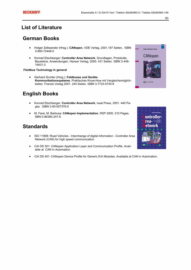
Eiserstraße 5 / D-33415 Verl / Telefon 05246/963-0 / Telefax 05246/963-149
93
List of Literature
German Books �� Holger Zeltwander (Hrsg.): CANopen, VDE Verlag, 2001.197 Seiten, ISBN
3-800-72448-0
�� Konrad Etschberger: Controller Area Network, Grundlagen, Protokolle, Bausteine, Anwendungen. Hanser Verlag, 2000. 431 Seiten. ISBN 3-446-19431-2
Fieldbus Technology in general
�� Gerhard Gruhler (Hrsg.): Feldbusse und Geräte-Kommunikationssysteme, Praktisches Know-How mit Vergleichsmöglich-keiten. Franzis Verlag 2001. 244 Seiten. ISBN 3-7723-5745-8
English Books �� Konrad Etschberger: Controller Area Network, Ixxat Press, 2001. 440 Pa-
ges. ISBN 3-00-007376-0
�� M. Farsi, M. Barbosa: CANopen Implementation, RSP 2000. 210 Pages. SBN 0-86380-247-8
Standards �� ISO 11898: Road Vehicles - Interchange of digital information - Controller Area
Network (CAN) for high speed communication.
�� CiA DS 301: CANopen Application Layer and Communication Profile. Avail-able at CAN in Automation.
�� CiA DS 401: CANopen Device Profile for Generic E/A Modules. Available at CAN in Automation.

Eiserstraße 5 / D-33415 Verl / Telefon 05246/963-0 / Telefax 05246/963-149
94
List of Abbreviations CAN
Controller Area Network. A serial bus system standardised in ISO 11898. The technology on which CANopen is based.
CiA CAN in Automation e.V.. An international association of manufacturers and users based in Erlangen, Germany.
COB Communication Object. A CAN telegram with up to 8 data bytes.
COB-ID Communication Object Identifier. Telegram address (not to be confused with the node address). CANopen uses the 11-bit identifier according to CAN 2.0A.
NMT Network Management. One of the service primitives of the CANopen specification. Network management is used to initialise the network and to monitor nodes.
PDO Process Data Object. A CAN telegram for the transfer of process data (e.g. I/O data).
RxPDO Receive PDO. PDOs are always identified from the point of view of the device under consideration. Thus a TxPDO with input data from an I/O module becomes an RxPDO from the controller's point of view.
SDO Service Data Object. A CAN telegram with a protocol for communication with data in the object directory (typi-cally parameter data).
TxPDO Transmit PDO (named from the point of view of the CAN node).

Eiserstraße 5 / D-33415 Verl / Telefon 05246/963-0 / Telefax 05246/963-149
95
Support and Service Beckhoff and their partners around the world offer comprehensive support and service, making available fast and competent assistance with all questions related to Beckhoff products and system solutions.
Beckhoff Support Support offers you comprehensive technical assistance, helping you no only with the application of individual Beckhoff products, but also with other, wide-ranging services:
�� world-wide support
�� design, programming and commissioning of complex automation systems
�� and extensive training program for Beckhoff system components
Hotline: +49(0)5246/963-157
Fax: +49(0)5246/963-199
e-mail: [email protected]
Beckhoff Service The Beckhoff Service Center supports you in all matters of after-sales service:
�� on-site service
�� repair service
�� spare parts service
�� hotline service
Hotline: +49(0)5246/963-460
Fax: +49(0)5246/963-479
e-mail: [email protected] You will find further support and service addresses on our Internet pages under http://www.beckhoff.com. You will also find documentation for Beckhoff components there.