Embed Size (px)
Citation preview

Bearing Capacity of Strip Foundation on SoftSoil Reinforced with Stone Columns
Using Method of Slices
M. Khalifa1(&), M. Etezad2, A. Hanna1, and M. Sabry3
1 Department of Building, Civil and Environmental Engineering,Concordia University, 1455 De Maisonneuve Blvd. W. Montréal,
Québec, Canada2 Golder Associates Ltd., 6925 Century Avenue,Suite #100, Mississauga, ON L5N 7K2, Canada3 Bechtel Corporation, 12011 Sunset Hills Road,
Suit 110, Reston, VA 20190, USA
Abstract. Stone columns are recognized as an environmently-friendly andcost-effective ground improvement technique. Stone columns are used in softsoil to increase the bearing capacity, reduce the settlement, increase the rate ofsettlement and reduce the liquefaction potential of the ground.This paper presents an analytical model utilizing the method of slices to
predict the ultimate bearing capacity of the soil reinforced with a group of stonecolumns. The soil within the failure zone was divided into slices and the limitequilibrium technique was adopted to perform the analysis. Shear forces andpassive earth pressure on the boundaries of each slice were determined. Byutilizing a circular failure plane, the minimum inter-slice force coefficients weredetermined.The analysis was carried out using the Morgenstern-Price method to estimate
the failure surface together with the bearing capacity of the reinforced ground.The failure surface was determined by trial and error to estimate the minimumfactor of safety. The ultimate bearing capacity was defined by increasing thefoundation load until the factor of safety of one was obtained. Results of thepresent theory were compared with those available in the literature, where agood agreement between the two was noted.
1 Introduction
Stone columns technique is a ground improvement method widely used over the pastdecades. Stone columns are stiffer and have higher shearing resistance than the nativesoft cohesive soil. This results in an increase of the soil bearing capacity and reduce inthe corresponding settlement (Etezad et al. (2015); Mitchell et al. (1985); Muir Woodet al. (2000); Priebe (1995)). Furthermore, stone columns have higher permeability thanthe native surrounding soil, which leads to reduction of the drainage path andaccordingly reduces the time required to complete the consolidation settlement(McKelvey et al. (2004)).
© Springer International Publishing AG 2018W. Frikha et al. (eds.), Soil Testing, Soil Stability and Ground Improvement,Sustainable Civil Infrastructures, DOI 10.1007/978-3-319-61902-6_8
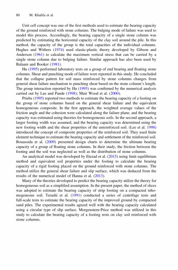
Unit cell concept was one of the first methods used to estimate the bearing capacityof the ground reinforced with stone columns. The bulging mode of failure was used tomodel this process. Accordingly, the bearing capacity of a single stone column waspredicted by estimating the horizontal capacity of the clay soil around the pile. In thismethod, the capacity of the group is the total capacities of the individual columns.Hughes and Withers (1974) used elastic-plastic theory developed by Gibson andAnderson (1961) to calculate the maximum vertical stress that can be carried by asingle stone column due to bulging failure. Similar approach has also been used byBalaam and Booker (1981).
Hu (1995) performed laboratory tests on a group of end bearing and floating stonecolumns. Shear and punching mode of failure were reported in this study. He concludedthat the collapse pattern for soil mass reinforced by stone columns changes fromgeneral shear failure mechanism to punching shear based on the stone column’s length.The group interaction reported by Hu (1995) was confirmed by the numerical analysiscarried out by Lee and Pande (1998); Muir Wood et al. (2000).
Priebe (1995) reported two methods to estimate the bearing capacity of a footing onthe group of stone columns based on the general shear failure and the equivalenthomogeneous composite. In the first approach, the weighted average values of thefriction angle and the cohesion were calculated along the failure plane, and the bearingcapacity was estimated using theories for homogeneous soils. In the second approach, alarger footing width was assumed, and the bearing capacity was determined using thenew footing width and the shear properties of the unreinforced soil. (Lee et al. 1998)introduced the concept of composite properties of the reinforced soil. They used finiteelement technique to estimate the bearing capacity and settlement of the reinforced soil.Bouassida et al. (2009) presented design charts to determine the ultimate bearingcapacity of a group of floating stone columns. In their study, the friction between thefooting and the soil was neglected as well as the distribution of stone columns.
An analytical model was developed by Etezad et al. (2015) using limit equilibriummethod and equivalent soil properties under the footing to calculate the bearingcapacity of a rigid footing placed on the ground reinforced with stone columns. Themethod utilize the general shear failure and slip surface, which was deduced from theresults of the numerical model of Hanna et al. (2013).
Many of the theories developed to predict the bearing capacity utilize the theory forhomogeneous soil as a simplified assumption. In the present paper, the method of sliceswas adopted to estimate the bearing capacity of strip footing on a compacted inho-mogeneous soil. Terashi et al. (1991) conducted a series of centrifuge tests andfull-scale tests to estimate the bearing capacity of the improved ground by compactedsand piles. The experimental results agreed well with the bearing capacity calculatedusing a circular type of slip surface. Morgenstern-Price method was utilized in thisstudy to calculate the bearing capacity of a footing rests on clay soil reinforced withstone columns.
80 M. Khalifa et al.

2 Bearing Capacity Calculations Based on Slip Circle
A 2-D model made of soft clay reinforced with stone columns was developed. The groundwas loaded with a uniform pressure to simulate the case of strip footing. The failure zonewas divided into 50 slides and the forces acting on each slide are shown in Fig. 1. Thelimit equilibrium method by Morgenstern et al. (1965) method was used in the computerprogram SIDE V-6.020, developed by Rocscience (2012), to calculate the minimum factorof safety of the circular slip surface (Fig. 2). The analysis was also check with theBishop’s Simplified method for comparison (Bishop 1955). The footing was loaded to theultimate capacity in the form of uniform pressure applied on the ground surface.
2.1 Validation
The results obtained from the present analysis was compared with the laboratory andnumerical results available in the literature (Hanna et al. (2013); Hu (1995); McKelveyet al. (2004)). Table 1 presents these comparison, where a good agreement can benoted. This further validate the methods of Morgenstern-Price and the Bishop’s Sim-plified method of slices as viable techniques to estimate the bearing capacity of claysoil reinforced by a group of stone columns. However, Bishop’s Simplified methodgenerally overestimates the factor of safety as compared to Morgenstern-Price method(Turnbull et al. 1967). Nevertheless, both approaches underestimate the bearingcapacity of the reinforced soil.
Uniform Load;[q
u]
Footing Width[B]
S S
b
Stone columns
Slip circle center
αi
wi
Ni
Ti
Ei+1 E
iV
i
Vi+1
Fig. 1. Forces acting on a slide in the slip circle
Bearing Capacity of Strip Foundation 81

Fig. 2. An example of the bearing capacity calculation using slip circle method
82 M. Khalifa et al.

Tab
le1.
Com
parisonbetweenthebearingcapacity
ofthereinforced
soilestim
ated
bythemetho
dof
slices
andtheavailableexperimentaland
numerical
results.
No.
Clayproperties
Stoneprop
erties
Area
replacem
ent
ratio
,As%
Footing
width,B
[m]
Surcharge
load,q
[kPa]
q u,
Measured
[kPa]
q u,B.S.
method
[kPa]
%Difference
from
measured
q u,Morgenstern
Pricemetho
d[kPa]
%Difference
from
measured
Cu
[kPa]
/c
[Degree]
cc [kN/m
3 ][D
egree]
cs [kN/m
3]
1a32
014
3417
.324
0.09
027
222
220
%21
8.8
18%
2a20
.50
9.9
3420
.340
0.05
016
016
51%
161
3%3b
10.5
013
.130
15.47
300.1
075
734%
71.7
3%4b
11.5
013
.130
15.47
300.1
079
801%
78.5
1%5c
512
1345
2135
2.5
2.6
352
270
24%
268.2
23%
6c5
1313
4019
352.5
2.6
280
250
12%
246.5
11%
7c5
1514
4521
352.5
2.8
420
380
9%38
0.2
10%
8c15
1514
4521
352.5
2.8
660
644
2%64
62%
9c10
1313
4019
302.62
2.6
366
270
27%
267
26%
10c
1513
1340
1930
2.62
2.6
458
350
24%
346.5
24%
aexperimantalworkof
McK
elveyet
al.(200
4)bexperimentalworkof
Hu(199
5)cnu
merical
workof
Hanna
etal.(201
3)
Bearing Capacity of Strip Foundation 83

2.2 Parametric Study
In this study, the results are presented in the form of improvement ratio (IR), which isdefined as the ratio of the capacity of improved soil to the capacity of the unimprovedsoil. In this analysis, the effect of the stone columns spacing to diameter ratio (S/D),and the number of stone column rows (N) on the bearing capacity at a givenreplacement ratio (As %) was performed. Each row of the stone columns was assumedas a trench with a width (b) and the spacing between trenches was considered the sameas the spacing between columns as shown in Fig. 3. The trench width was calculatedusing Eq. 1. In this case, the replacement ratio (As) was calculated using Eq. 2. Theratio of S/D was examined in the range of 1 to 3.0 as given in Table 2.
b ¼ p� D2
4� Sð1Þ
As ¼ N � bB
¼ N � p� D2
4� S� Bð2Þ
Where,N is the number of stone columns rows, b is the trench width, B is footing width, D
is stone column diameter, and S is the spacing between stone columns.Moreover, this method was also used to determine the effect of the undrained
strength of the clay soil (Cu), and the replacement ratio (As %). In this analysis, thereplacement ratio ranged from 10% to 30% which widely used in practice (Hanna et al.(2013); Hu (1995)). The range of the other parameters believed to govern the bearingcapacity are presented in Table 3.
The effect of the column arrangement on the bearing capacity was also investigated.Figure 4 presents the spacing/ diameter ratio of stone columns versus replacementratios, assuming all other parameters are constant. It can be noted that the bearingcapacity increases with the increase of the replacement ratio. Also. It can be noted thatthe spacing between stone columns slightly influences on the improvement ratio. Forlow replacement ratio (<10%), the improvement ratio is almost constant, which agreedwell with Castro (2014) observation. However, the improvement ratio reduces with theincrease of the columns spacing ratio; for higher replacement ratio (20%, and 30%),which confirm that for small spacing between columns, the lateral support from thesurrounding soil increases and accordingly, will show significant improvement.
Regarding the effect of the clay shearing resistance, it is noticeable that theimprovement ratio reduces with the increase of shear strength of clay soil (Cu) for thesame spacing/ diameter ratio as shown in Fig. 5. Contrary, the improvement ratioraised by the increase of the stone columns shearing resistance angle (/) as shown inFig. 6.
The influence of stone columns number under the footing has been also investi-gated. In this analysis, the columns number varied from N = 1 to N = 4. The columnsdiameter ranged from 0.3 m to 1.6 m, which covers the maximum and minimumranges that may be used in practice. Figure 7 presents the effect of the stone columnsnumber on the bearing capacity, and it can be noted that there is no remarkable change
84 M. Khalifa et al.

Fig. 3. Stone columns arrangement
Bearing Capacity of Strip Foundation 85

Table 2. Range of stone columns dimensions used in parametric study
Area replacementratio, As %
No. ofcolumns, N
Columndiameter,D [m]
Columnspacing,S [m]
Spacing/Diameterratio, S/D
Trenchwidthb [m]
10% 1 0.70 0.70 1.00 0.502 0.35 0.38 1.09 0.252 0.40 0.50 1.25 0.252 0.45 0.63 1.40 0.252 0.49 0.75 1.53 0.252 0.63 1.25 1.98 0.252 0.89 2.50 2.80 0.25
20% 1 1.30 1.30 1.00 1.002 0.69 0.75 1.09 0.502 0.80 1.00 1.25 0.502 0.89 1.25 1.40 0.502 0.98 1.50 1.53 0.502 1.26 2.50 1.98 0.502 1.69 4.50 2.66 0.503 0.46 0.50 1.09 0.333 0.53 0.67 1.25 0.333 0.59 0.83 1.40 0.333 0.65 1.00 1.53 0.333 0.84 1.67 1.98 0.333 1.00 2.33 2.34 0.33
30% 1 2.10 2.10 1.00 1.502 1.04 1.13 1.09 0.752 1.20 1.50 1.25 0.752 1.34 1.88 1.40 0.752 1.47 2.25 1.53 0.752 1.89 3.75 1.98 0.753 0.69 0.75 1.09 0.503 0.80 1.00 1.25 0.503 0.89 1.25 1.40 0.503 0.98 1.50 1.53 0.503 1.13 2.00 1.77 0.504 0.52 0.56 1.09 0.384 0.60 0.75 1.25 0.384 0.67 0.94 1.40 0.384 0.73 1.13 1.53 0.384 0.85 1.50 1.77 0.38
86 M. Khalifa et al.

Fig. 4. Improvement ratio (IR) versus S/D for different replacement area, Cu = 5 kPa, U = 35o:(a) As = 10%; (b) As = 20%; (c) As = 30%
Bearing Capacity of Strip Foundation 87

Fig. 5. Effect of shear resistance of clay on the improvement ratio for different replacementratios, U = 35o: (a) S/D = 1.25; (b) S/D = 1.50; (c) S/D = 2.00
88 M. Khalifa et al.

Table 3. Range of parameter used in the parametric study
Parameter Range of value
Cohesion of clay soil, Cu [kPa] 5, 10, and 15Unit weight of clay soil, cc [kN/m3] 18Angle of shear resistance of stone, /s [Degree] 35, 38, and 40Unit weight of stone, cs [kN/m3] 20Stone column diameter, D [m] 0.3–1.60Stone column diameter to spacing ratio 1.00–2.50Replacement area, As [%] 10, 20, and 30Footing width, B [m] 5
Fig. 6. Effect of shear resistance of stone on the improvement ratio for different replacementratios, Cu = 10 kPa; S/D = 1.50
Fig. 7. The relation between number of stone column rows versus the improvement ratio, atS/D = 1.5, Cu = 5 kPa, U = 35o
Bearing Capacity of Strip Foundation 89

in the improvement ratio particularly for low replacement ratio (<10%). However, thereis a slight reduction in the improvement ratio for higher values of replacement ratio(30%). For a large number of stone columns, a small diameter was used to keep thereplacement ratio constant. By reducing the column’s diameter more load will betransferred to the clay soil (less strength material), which lead to the reduction in theimprovement ratio (Black et al. (2007); Hanna et al. (2013))
3 Conclusions
Morgenstern-Price method of slices was used to calculate the bearing capacity of a softclay reinforced with stone columns. The theory developed compared well with theavailable results in the literature. Parametric study was conducted on the parametersbelieved to govern the behavior of this system. The following was concluded:
1- Morgenstern-Price method of slices was successfully used to estimate the bearingcapacity of reinforced clay soil.
2- (IR) significantly increases with the increrase of the replacement ratio.3- (IR) reduces due to the increase of the spacing/ diameter ratio (S/D)4- Based on the results of the present study, in order to optimize the benefit of the use
of reinforced soft clay with stone columns is to use a ratio of columns spacing tocolumns diameter (S/D) equal to 1.5
5- For the same stone columns arrangement and shear resistance (diameter, spacing)the improvement ratio (IR) increases with a decrease of the shear strength ofsurrounding clay. However, the ultimate bearing capacity of the system is signif-icantly increased due to the increase of the shear strength of the clay soil as well asthe stone. Furthermore, the improvement ratio (IR) increases with the increase ofthe stone columns shearing resistance angle.
Acknowledgments. The financial support received from Concordia University isacknowledged.
References
Balaam, N., Booker, J.R.: Analysis of rigid rafts supported by granular piles. Int. J. Numer. Anal.Meth. Geomech. 5(4), 379–403 (1981)
Bishop, A.W.: The use of the slip circle in the stability analysis of slopes. Geotechnique 5(1), 7–17 (1955)
Black, J., Sivakumar, V., McKinley, J.: Performance of clay samples reinforced with verticalgranular columns. Can. Geotech. J. 44(1), 89–95 (2007)
Bouassida, M., Jellali, B., Porbaha, A.: Limit analysis of rigid foundations on floating columns.Int. J. Geomech. 9(3), 89–101 (2009)
Castro, J.: Numerical modelling of stone columns beneath a rigid footing. Comput. Geotech. 60,77–87 (2014)
90 M. Khalifa et al.

Etezad, M., Hanna, A., Ayadat, T.: Bearing capacity of a group of stone columns in soft soil. Int.J. Geomech. 15(2) (2015)
Gibson, R., Anderson, W.: In situ measurement of soil properties with the pressuremeter. CivilEng. Public Works Rev. 56(658), 615–618 (1961)
Hanna, A., Etezad, M., Ayadat, T.: Mode of failure of a group of stone columns in soft soil. Int.J. Geomech. 13(1), 87–96 (2013)
Hu, W.: Physical modelling of group behaviour of stone column foundation. (Ph.D. dissertation),University of Glasgow, UK (1995)
Hughes, J., Withers, N.: Reinforcing of soft cohesive soils with stone columns. Ground Eng. 7(3), 42–49 (1974)
Lee, J.S., Pande, G.N.: Analysis of stone-column reinforced foundations. Int. J. Numer. Anal.Meth. Geomech. 22(12), 1001–1020 (1998)
McKelvey, D., Sivakumar, V., Bell, A., Graham, J.: A Laboratory Model Study of thePerformance of Vibro Stone Columns in Soft Clay. J. Geotech. Eng. 152, 1–13 (2004)
Mitchell, J.K., Huber, T.R.: Performance of a stone column foundation. J. Geotech. Eng. 111(2),205–223 (1985)
Morgenstern, N., Price, V.E.: The analysis of the stability of general slip surfaces. Geotechnique15(1), 79–93 (1965)
Muir Wood, D., Hu, W., Nash, D.: Group effects in stone column foundations: model tests.Geotechnique 50(6), 689–698 (2000)
Priebe, H.J.: The design of vibro replacement. Ground Eng. 28(10), 31 (1995)Rocscience: SLIDE 6.0—2D Slope Stability Analysis for Soil and Rock Slopes. Rocscience Inc.
(2012)Terashi, M., Kitazume, M., Minagawa, S.: Bearing capacity of improved ground by sand
compaction piles. In: Deep Foundation Improvements: Design, Construction, and Testing.ASTM International (1991)
Turnbull, W. J., Hvorslev, M.J.: Special problems in slope stability. J. Soil Mech. Found. Div.(1967)
Bearing Capacity of Strip Foundation 91