Embed Size (px)
Citation preview
ARCH 331 Note Set 7 Su2011abn
1
A
A
B
B
F
FF
F
FF
Beam Structures and Internal Forces
Notation:
a = algebraic quantity, as is b, c, d
A = name for area
b = intercept of a straight line
d = calculus symbol for differentiation
(C) = shorthand for compression
F = name for force vectors, as is P, F’, P’
= internal axial force
Fx = force component in the x direction
Fy = force component in the y direction
FBD = free body diagram
L = beam span length
m = slope of a straight line
M = internal bending moment
M(x) = internal bending moment as a
function of distance x
R = name for reaction force vector
(T) = shorthand for tension
V = internal shear force
V(x) = internal shear force as a function of
distance x
w = name for distributed load
W = name for total force due to distributed
load
x = horizontal distance
y = vertical distance
º = symbol for order of curve
= symbol for integration
= calculus symbol for small quantity
= summation symbol
BEAMS
- Important type of structural members (floors, bridges, roofs)
- Usually long, straight and rectangular
- Have loads that are usually perpendicular applied at points along the length
Internal Forces 2
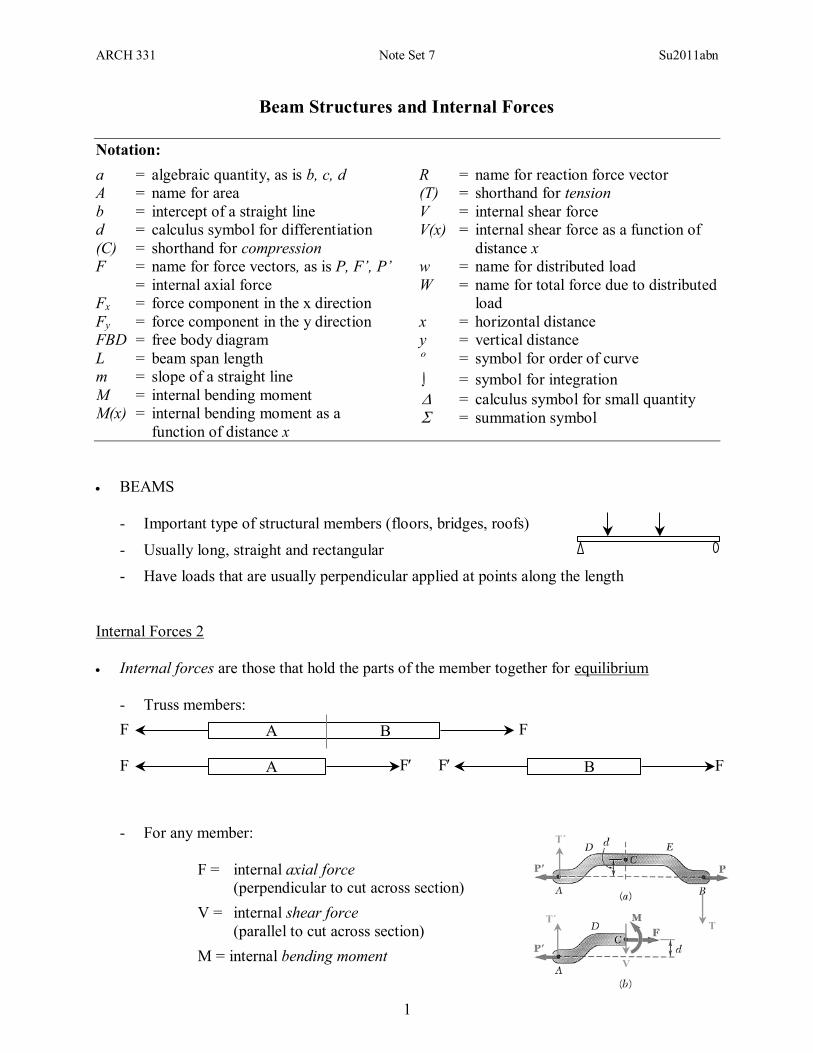
Internal forces are those that hold the parts of the member together for equilibrium
- Truss members:
- For any member:
F = internal axial force
(perpendicular to cut across section)
V = internal shear force
(parallel to cut across section)
M = internal bending moment
T´
V
T´
T
ARCH 331 Note Set 7 Su2011abn
2
R
V
M
V
M
Support Conditions & Loading
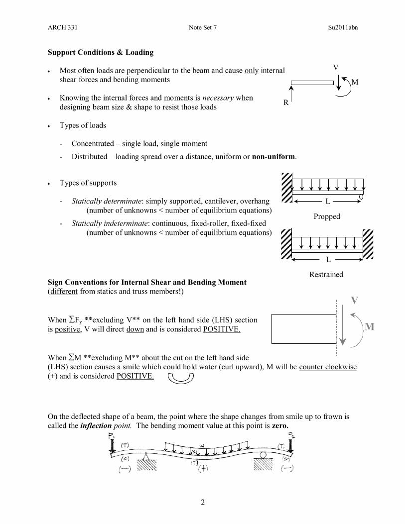
Most often loads are perpendicular to the beam and cause only internal
shear forces and bending moments
Knowing the internal forces and moments is necessary when
designing beam size & shape to resist those loads
Types of loads
- Concentrated – single load, single moment
- Distributed – loading spread over a distance, uniform or non-uniform.
Types of supports
- Statically determinate: simply supported, cantilever, overhang
(number of unknowns < number of equilibrium equations)
- Statically indeterminate: continuous, fixed-roller, fixed-fixed
(number of unknowns < number of equilibrium equations)
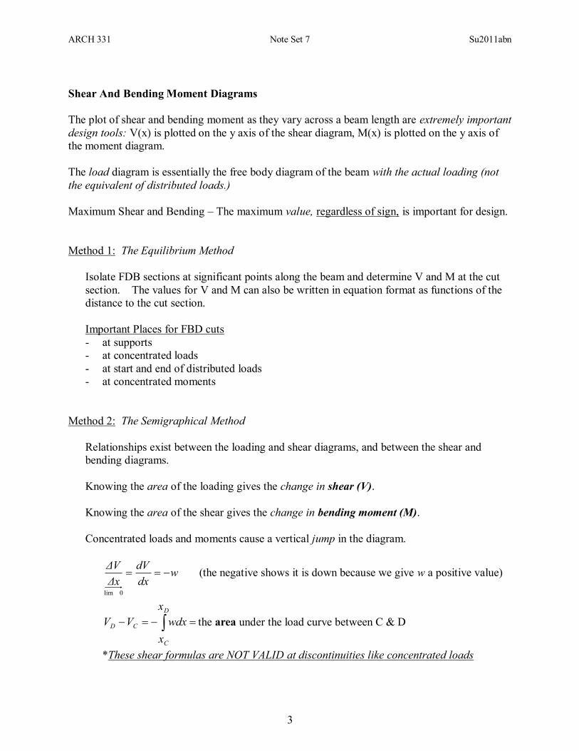
Sign Conventions for Internal Shear and Bending Moment
(different from statics and truss members!)
When Fy **excluding V** on the left hand side (LHS) section
is positive, V will direct down and is considered POSITIVE.
When M **excluding M** about the cut on the left hand side
(LHS) section causes a smile which could hold water (curl upward), M will be counter clockwise
(+) and is considered POSITIVE.
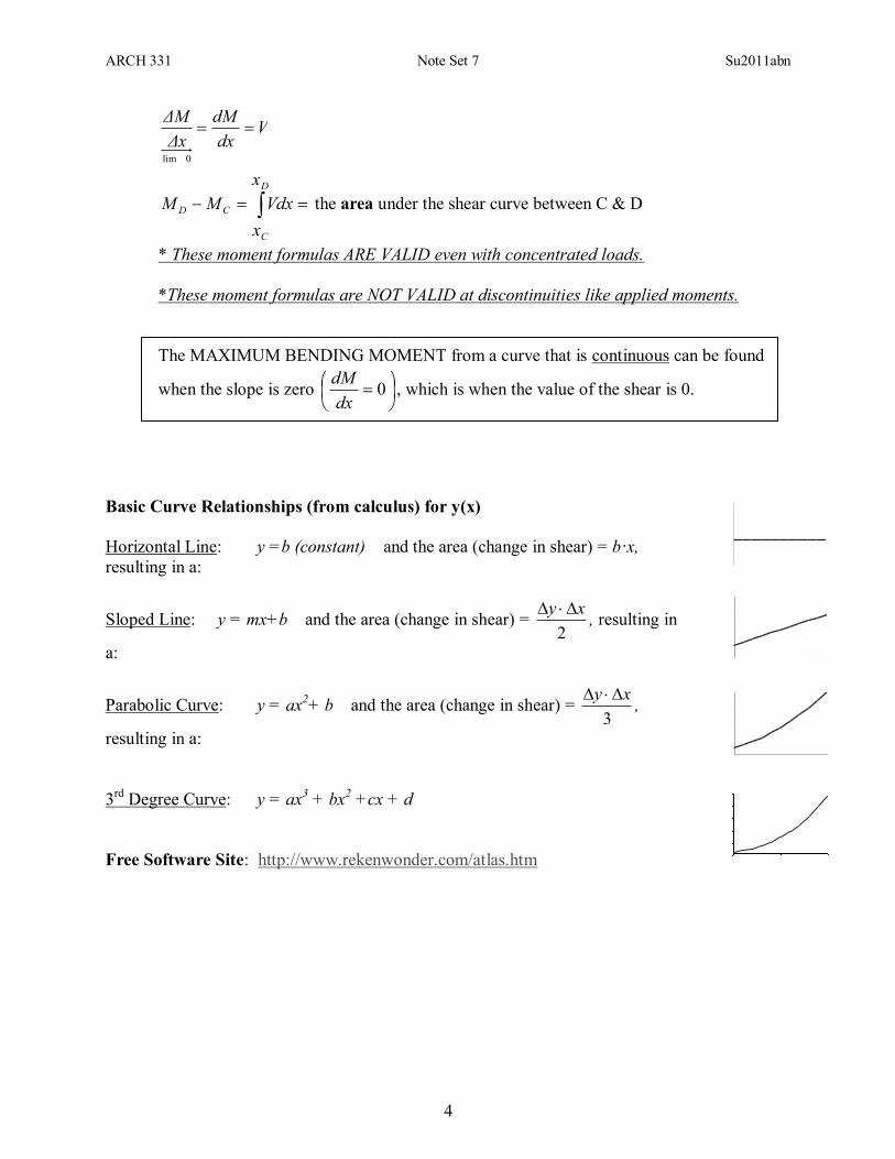
On the deflected shape of a beam, the point where the shape changes from smile up to frown is
called the inflection point. The bending moment value at this point is zero.
L
L
Propped
Restrained
ARCH 331 Note Set 7 Su2011abn
3
Shear And Bending Moment Diagrams
The plot of shear and bending moment as they vary across a beam length are extremely important
design tools: V(x) is plotted on the y axis of the shear diagram, M(x) is plotted on the y axis of
the moment diagram.
The load diagram is essentially the free body diagram of the beam with the actual loading (not
the equivalent of distributed loads.)
Maximum Shear and Bending – The maximum value, regardless of sign, is important for design.
Method 1: The Equilibrium Method
Isolate FDB sections at significant points along the beam and determine V and M at the cut
section. The values for V and M can also be written in equation format as functions of the
distance to the cut section.
Important Places for FBD cuts
- at supports
- at concentrated loads
- at start and end of distributed loads
- at concentrated moments
Method 2: The Semigraphical Method
Relationships exist between the loading and shear diagrams, and between the shear and
bending diagrams.
Knowing the area of the loading gives the change in shear (V).
Knowing the area of the shear gives the change in bending moment (M).
Concentrated loads and moments cause a vertical jump in the diagram.
wdx
dV
Δx
ΔV
0lim
(the negative shows it is down because we give w a positive value)
D
C
CD
x
x
wdxVV the area under the load curve between C & D
*These shear formulas are NOT VALID at discontinuities like concentrated loads
ARCH 331 Note Set 7 Su2011abn
4
Vdx
dM
Δx
ΔM
0lim
D
C
CD
x
x
VdxMM the area under the shear curve between C & D
* These moment formulas ARE VALID even with concentrated loads.
*These moment formulas are NOT VALID at discontinuities like applied moments.
The MAXIMUM BENDING MOMENT from a curve that is continuous can be found
when the slope is zero
0
dx
dM, which is when the value of the shear is 0.
Basic Curve Relationships (from calculus) for y(x)
Horizontal Line: y =b (constant) and the area (change in shear) = b·x,
resulting in a:
Sloped Line: y = mx+b and the area (change in shear) = 2
xy , resulting in
a:
Parabolic Curve: y = ax2+ b and the area (change in shear) =
3
xy ,
resulting in a:
3rd
Degree Curve: y = ax3 + bx
2 +cx + d
Free Software Site: http://www.rekenwonder.com/atlas.htm
ARCH 331 Note Set 7 Su2011abn
5
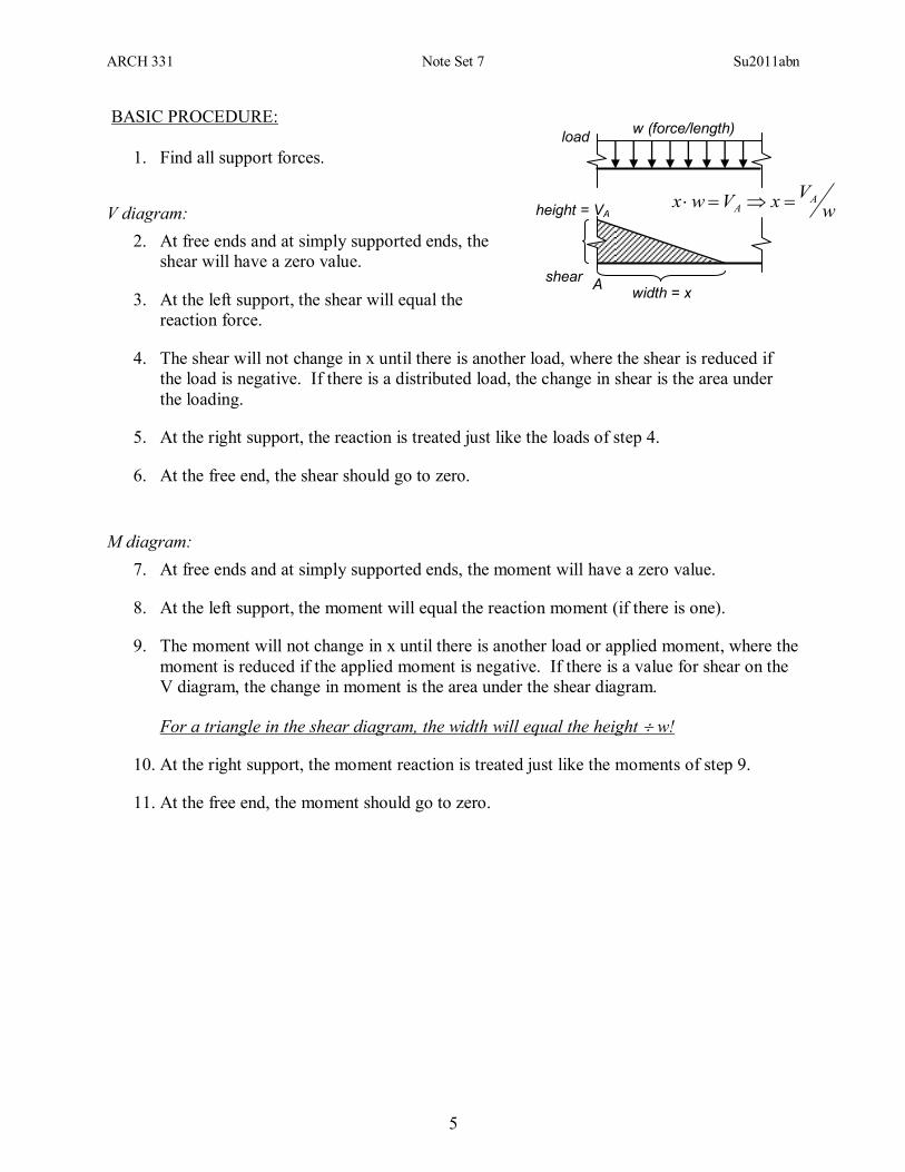
BASIC PROCEDURE:
1. Find all support forces.
V diagram:
2. At free ends and at simply supported ends, the
shear will have a zero value.
3. At the left support, the shear will equal the
reaction force.
4. The shear will not change in x until there is another load, where the shear is reduced if
the load is negative. If there is a distributed load, the change in shear is the area under
the loading.
5. At the right support, the reaction is treated just like the loads of step 4.
6. At the free end, the shear should go to zero.
M diagram:
7. At free ends and at simply supported ends, the moment will have a zero value.
8. At the left support, the moment will equal the reaction moment (if there is one).
9. The moment will not change in x until there is another load or applied moment, where the
moment is reduced if the applied moment is negative. If there is a value for shear on the
V diagram, the change in moment is the area under the shear diagram.
For a triangle in the shear diagram, the width will equal the height w!
10. At the right support, the moment reaction is treated just like the moments of step 9.
11. At the free end, the moment should go to zero.
shear
load
height = VA
w (force/length)
width = x A
wV
xVwx AA
ARCH 331 Note Set 7 Su2011abn
6
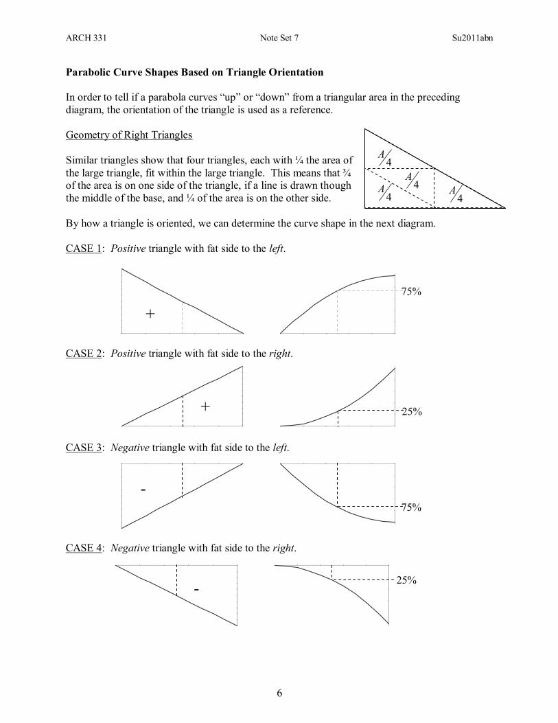
Parabolic Curve Shapes Based on Triangle Orientation
In order to tell if a parabola curves “up” or “down” from a triangular area in the preceding
diagram, the orientation of the triangle is used as a reference.
Geometry of Right Triangles
Similar triangles show that four triangles, each with ¼ the area of
the large triangle, fit within the large triangle. This means that ¾
of the area is on one side of the triangle, if a line is drawn though
the middle of the base, and ¼ of the area is on the other side.
By how a triangle is oriented, we can determine the curve shape in the next diagram.
CASE 1: Positive triangle with fat side to the left.
CASE 2: Positive triangle with fat side to the right.
CASE 3: Negative triangle with fat side to the left.
CASE 4: Negative triangle with fat side to the right.
4A
4A
4A
4A
25% -
75%
-
25% +
75%
+
ARCH 331 Note Set 7 Su2011abn
7
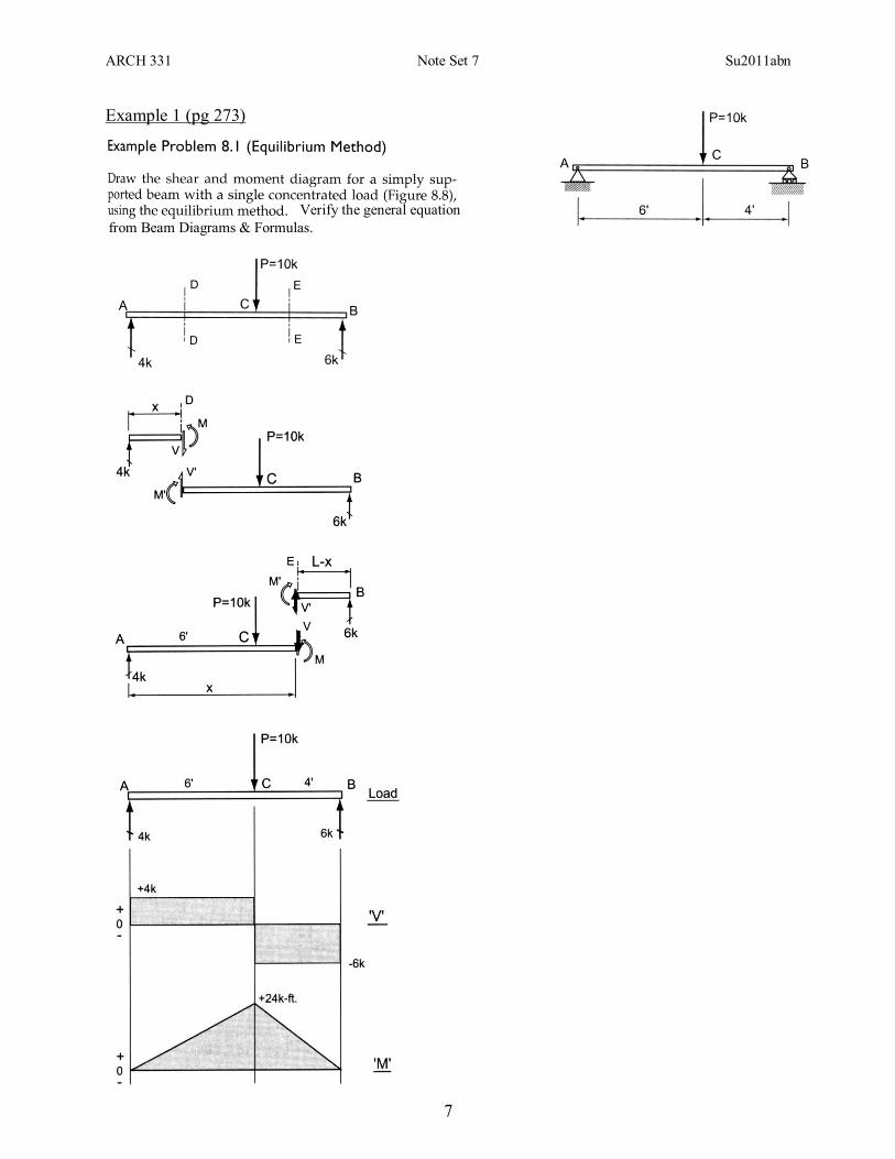
Example 1 (pg 273)
Verify the general equation
from Beam Diagrams & Formulas.
ARCH 331 Note Set 7 Su2011abn
8
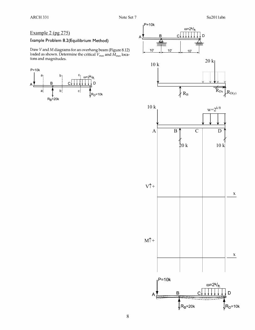
Example 2 (pg 275)
20 k 10 k
RDx RB
RD(y)
10 k w=2
k/ft
20 k 10 k
x
V+
x
M+
A B C D
ARCH 331 Note Set 7 Su2011abn
9
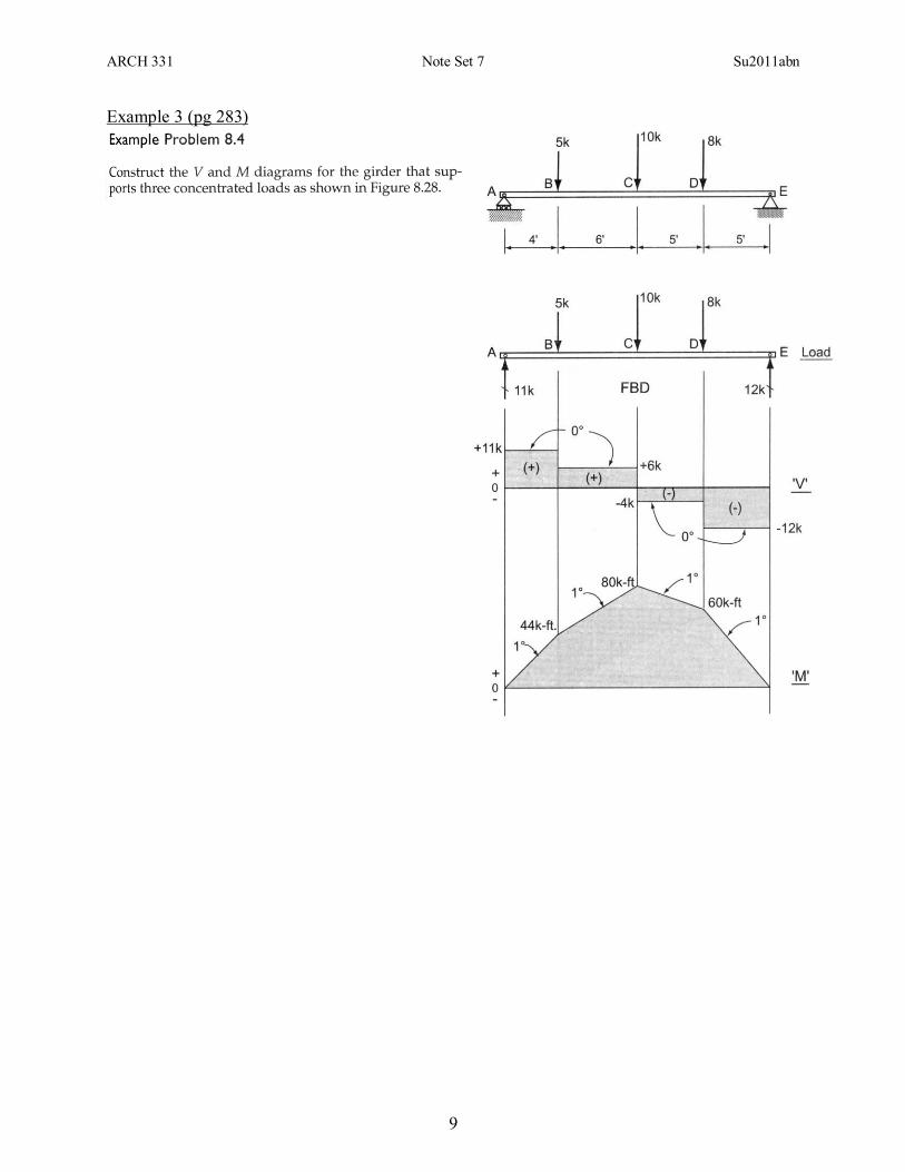
Example 3 (pg 283)
ARCH 331 Note Set 7 Su2011abn
10
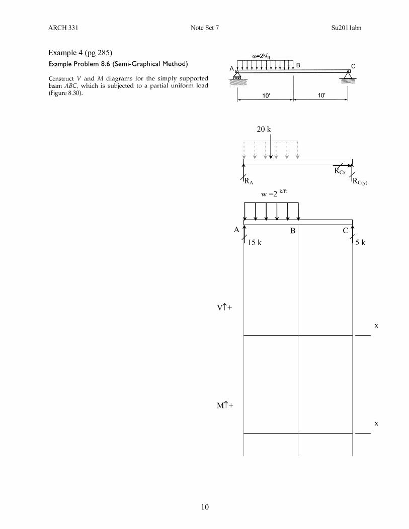
Example 4 (pg 285)
R
By
M
RB
20 k
RCx
RC(y)
x
V+
x
M+
5 k
RA
15 k
w =2 k/ft
A B C
ARCH 331 Note Set 7 Su2011abn
11
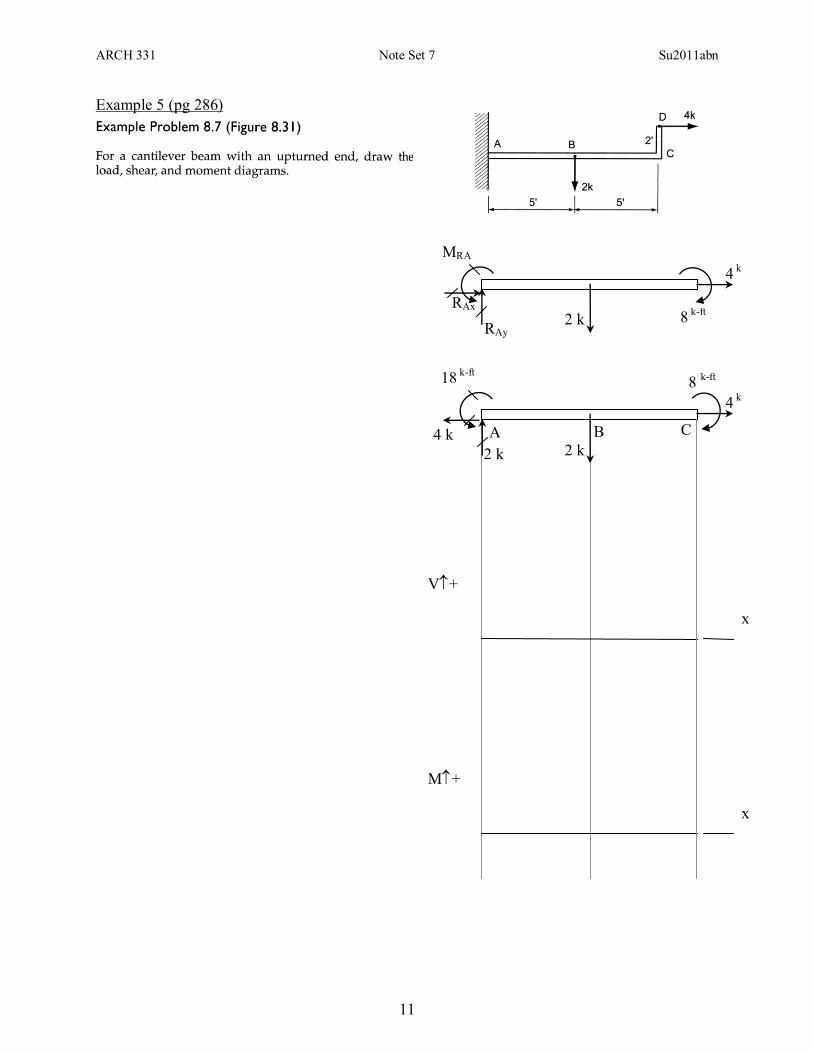
Example 5 (pg 286)
2 k
RAx
RAy
8 k-ft
x
V+
x
M+
8 k-ft
A
MRA
2 k
2 k
18 k-ft
B C 4 k
4 k
4 k
ARCH 331 Note Set 7 Su2011abn
12
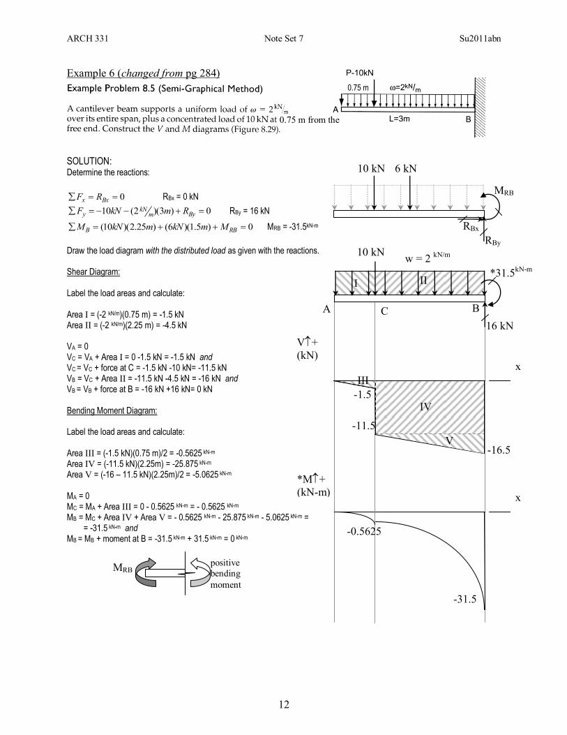
Example 6 (changed from pg 284)
SOLUTION: Determine the reactions:
0 Bxx RF RBx = 0 kN
0)3)(2(10 BymkN
y RmkNF RBy = 16 kN
0)5.1)(6()25.2)(10( RBB MmkNmkNM MRB = -31.5kN-m
Draw the load diagram with the distributed load as given with the reactions. Shear Diagram: Label the load areas and calculate: Area I = (-2 kN/m)(0.75 m) = -1.5 kN Area II = (-2 kN/m)(2.25 m) = -4.5 kN VA = 0 VC = VA + Area I = 0 -1.5 kN = -1.5 kN and VC = VC + force at C = -1.5 kN -10 kN= -11.5 kN VB = VC + Area II = -11.5 kN -4.5 kN = -16 kN and VB = VB + force at B = -16 kN +16 kN= 0 kN Bending Moment Diagram: Label the load areas and calculate: Area III = (-1.5 kN)(0.75 m)/2 = -0.5625 kN-m
Area IV = (-11.5 kN)(2.25m) = -25.875 kN-m Area V = (-16 – 11.5 kN)(2.25m)/2 = -5.0625 kN-m MA = 0 MC = MA + Area III = 0 - 0.5625 kN-m = - 0.5625 kN-m MB = MC + Area IV + Area V = - 0.5625 kN-m - 25.875 kN-m - 5.0625 kN-m = = -31.5 kN-m and MB = MB + moment at B = -31.5 kN-m + 31.5 kN-m = 0 kN-m
0.75 m
6 kN 10 kN
RBx
RBy
MRB
x
V+
(kN)
x
*M+
(kN-m)
-1.5
16 kN
*31.5kN-m
w = 2 kN/m
A B C
I II
III
IV
V
-11.5
-16.5
-0.5625
-31.5
10 kN
0.75 m from the
MRB positive
bending
moment
ARCH 331 Note Set 7 Su2011abn
13
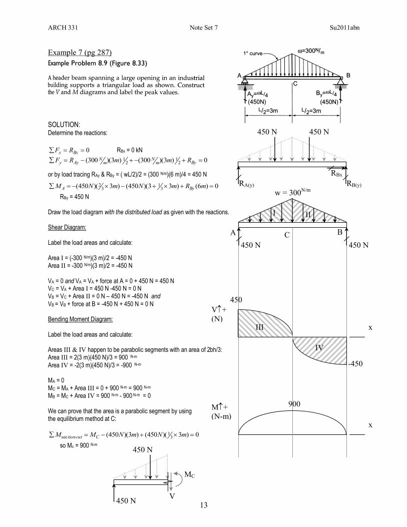
Example 7 (pg 287)
SOLUTION: Determine the reactions:
0 Bxx RF RBx = 0 kN
0)3)(300()3)(300( 21
21 Bym
Nm
NAyy RmmRF
or by load tracing RAy & RBy = ( wL/2)/2 = (300 N/m)(6 m)/4 = 450 N
0)6()33)(450()3)(450( 31
32 mRmNmNM ByA
RBy = 450 N
Draw the load diagram with the distributed load as given with the reactions. Shear Diagram: Label the load areas and calculate: Area I = (-300 N/m)(3 m)/2 = -450 N Area II = -300 N/m)(3 m)/2 = -450 N VA = 0 and VA = VA + force at A = 0 + 450 N = 450 N VC = VA + Area I = 450 N -450 N = 0 N VB = VC + Area II = 0 N – 450 N = -450 N and VB = VB + force at B = -450 N + 450 N = 0 N Bending Moment Diagram: Label the load areas and calculate: Areas III & IV happen to be parabolic segments with an area of 2bh/3: Area III = 2(3 m)(450 N)/3 = 900 N-m
Area IV = -2(3 m)(450 N)/3 = -900 N-m MA = 0 MC = MA + Area III = 0 + 900 N-m = 900 N-m MB = MC + Area IV = 900 N-m - 900 N-m = 0 We can prove that the area is a parabolic segment by using the equilibrium method at C:
0)3)(450()3)(450( 31
sec mNmNMM Ccuttion
so Mc = 900 N-m
450 N
RBx
RB(y)
x
V+
(N)
x
M+
(N-m)
450 N
A B
RA(y)
450 N
C
450 N
w = 300N/m
I II
450
-450
900
III
IV
450 N
MC
V 450 N