Embed Size (px)
Citation preview

beambeam
LARP Rotatable CollimatorMechanical Engineering Discussion
03 October 2008
Phase II CERN ME Video Mtg.
Tom Markiewicz/SLAC
BNL - FNAL- LBNL - SLAC
US LHC Accelerator Research Program

CERN Video Mtg - 03 October 2008 RC ME Questions - T. MarkiewiczSlide n° 2 / 16
2008-10-03 Discussion Questions
1) Discuss your latest results of thermo-mechanical calculations for nominal working conditions (1h and 12 min. beam life time):
• in which way is the "effective length" of the jaw under thermal load calculated ?
2) Dimensioning of cooling pipes (material and size), water flow rate, water velocity (possible erosion/corrosion problems), temp increase of the water?
3) Thermo-mechanical calculations for Asynchronous beam dump: – impact on TCP with shower on TCSM vs. direct impact on TCSM – have both cases been considered?– Discuss about method of calculation and results obtained. – Further analysis foreseen?
4) Is any sensor foreseen to detect a beam impact on collimator jaws?
5) Results of bake-out test? at which temperature was it performed?
6) Use of any lubricant for moving parts under vacuum (bearings, Geneva mechanism...)?

CERN Video Mtg - 03 October 2008 RC ME Questions - T. MarkiewiczSlide n° 3 / 16
LHC Phase II Base Conceptphysical constraintscurrent jaw design
beambeam
• beam spacing: geometrical constraint
• Length available 1.47 m flange - flange
• Jaw translation mechanism and collimator support base: LHC Phase I
• >10 kW per jaw Steady State heat dissipation (material dependent)
Cu coolant supply tubes twist to allow jaw rotation
Hub area
Glidcop Cu Mo
Cantilever Mo shaft @ both ends
Helical cooling channels
25mm below surface
20 facets

CERN Video Mtg - 03 October 2008 RC ME Questions - T. MarkiewiczSlide n° 4 / 16
Results of Thermo-mechanical calculations for nominal working conditions
Large amount of data presented over 2004-2006– Jaw Material selection: Copper– Continuous azimuthally wound cooling
Basic design “approved” by Assmann, Bertarelli et al summer 2005
All calculations refer to the FIRST secondary downstream of primaries. Have discussed:– if copper RC placed here, increase aperture from 7 to 8 sigma– keeping only C-C Phase I secondary in this location
Design concept of “Jaw-Hub-Shaft” in 2006 improves performance under nominal 1hr and 12min beam lifetime conditions by x5

CERN Video Mtg - 03 October 2008 RC ME Questions - T. MarkiewiczSlide n° 5 / 16
June 2006Introduce new jaw-hub-shaft design which
eliminates central stop & flexible springs
x5 improvement in thermal deformation1260 um 236 um (60kW/jaw, 12min) 426 um 84 um (12kW/jaw, t=60min)

CERN Video Mtg - 03 October 2008 RC ME Questions - T. MarkiewiczSlide n° 6 / 16
Comparison of Hollow Moly shaft to Solid Copper Shaft:
Improved deflectionsbut necessitated Moly/Cu Brazing R&D
Solid Cu, 75cm tapered jaw, asymmetric hub
Tubular Moly, 95 cm straight jaw, symmetric hub
Steady State=1 hour
= 12 min for 10 sec
Steady State=1 hour
= 12 min for 10 sec
Gravity sag 200 um 67.5 um
Power absorbed 11.7 kW 58.5 kW 12.9 kW 64.5 kW
Peak Temp. 66.3 °C 197 °C 66 °C 198 °C
Midjaw x 100 um 339 um 83.6 um 236 um
Effective Length 51 cm 25 cm 74 cm 39 cm
Sagitta 221 um 881 um 197 um 781 um
Effective length defined by 100um sagitta

CERN Video Mtg - 03 October 2008 RC ME Questions - T. MarkiewiczSlide n° 7 / 16
Dimensioning of cooling pipes (material and size), water flow rate, water velocity (possible erosion/corrosion
problems), temp increase of the water?
Note location of most recent writeup:
http://www-project.slac.stanford.edu/ilc/larp/rc/FY07-Q2_RC_Design_Update.pdf
Tubing Variations Under Consideration
– Copper Nickel tubing: need to test rigidity against winding on mandrel
– Round tubing: 10mm OD, 8mm ID:
Note: In current square tubing design, wall is 1.5mm and top wall thinned by 0.25mm to 1.25mm total to prep surface for brazing to jaws
Component dimension units Jaw OD tangent to 20-faceted surface 136 mm Jaw OD to facet vertices 137.7 mm Jaw ID 66 mm Jaw length, including 10mm (in z) x 15o taper on each end 930 mm Mo Shaft OD 64 mm Mo Shaft ID 44 mm Hub length (centered) 150 mm Cooling tube OD x ID (square x square) 10 x 7 mm Embedded helix – center radius 80 mm Helix – number of turns ~47 - Cooling tube length – helix + entry + exit from vac tank ~16 m Flow per jaw 9 l/min Velocity 3 m/s Water temperature rise (SS 12.8 kW per jaw) 20.3 C Pressure drop 2.4 bar

CERN Video Mtg - 03 October 2008 RC ME Questions - T. MarkiewiczSlide n° 8 / 16
Thermo-mechanical calculations for Asynchronous beam dumpPermanent deformation AND Molten copper
Case: beam abort system fires asynchronously, 8 full intensity bunches into jawModel: - increased resolution 3-D ANSYS & FLUKA models - Thermal heating/cooling analysis followed by quasi-static stress analysis - Jaw ends constrained in z during 200 ns, released for 60 sec cool-down - 0.27 MJ deposited in 200 ns - Molten material removed from model after 200 nsResult: - 57e3 peak temperature (ultra fine model) - 54 m permanent deformation (concave)
5mmmelt
2.5mm x 2.5mm
elementsTmax = 57 e3
Shower max – extent of melted zone
3.3mm
Cooling
tubes
Shaft
Jaw facets

CERN Video Mtg - 03 October 2008 RC ME Questions - T. MarkiewiczSlide n° 9 / 16
Accident CasePermanent Jaw deflection, ux, after 60 sec cool-down
Melted material removed
In-plane permanent deflection
54 umBeam side
After energy deposit (200ns – 60 sec), z-constraints released. Original analysis used this constraint at all times.
- What happens to vaporized/melted material?- How to use deformed jaw?

CERN Video Mtg - 03 October 2008 RC ME Questions - T. MarkiewiczSlide n° 10 / 16
Longitudinal Temperature Distribution of Collimator Hit with 9E11 7 Tev Protons
120 cm long coppersecondary collimator jaw
Missteered beam (9E11 protons)
Copper fractures @ ≈200 ˚C
melting
25-30 cm
above Cu melting

CERN Video Mtg - 03 October 2008 RC ME Questions - T. MarkiewiczSlide n° 11 / 16
2.5 cm
Cross section at shower max.
Copper
Fracture temp. of copper is about 200 deg C
840 deg C
Copper
Hit Collimator Adjacent Collimator
Temperature Profiles of Hit & Adjacent Collimators

CERN Video Mtg - 03 October 2008 RC ME Questions - T. MarkiewiczSlide n° 12 / 16
Another accident CaseBeam hits the horizontal primary collimator
Copper
250 ˚C

CERN Video Mtg - 03 October 2008 RC ME Questions - T. MarkiewiczSlide n° 13 / 16
Is any sensor foreseen to detect a beam impact on collimator jaws?
Not precluded
Would love to have a design contributed that we can incorporate
What are plans for this functionality in the CERN designs
What about “acoustic sensors”’
Area of transition RF foil, which is stationary, is a possible location

CERN Video Mtg - 03 October 2008 RC ME Questions - T. MarkiewiczSlide n° 14 / 16
Results of bake-out test? at which temperature was it performed?
Process:– “Standard” PEP-II Beamline bake-out sequence:– Vacuum vessel separately baked 200°C for several days
• 3.7E-9 torr
– Jaw H fired at 850°C before bake to accelerate bake-out process– Bake 200°C several days with 24 hour excursion to 300°C
• paranoia
RGA Zero hydrocarbons
(mass >40) at 150 deg C
Final RGA & pressure on 6 Oct.
RC Test Jaw Vacuum Sept-2009
1.00E-09
1.00E-08
1.00E-07
1.00E-06
020406080100120140160
Temperature (degrees C)
Pre
ssu
re (
torr
)
Temp Pressure150 1.40E-07
58 3.20E-0827.6 8.20E-0927.2 7.40E-09

CERN Video Mtg - 03 October 2008 RC ME Questions - T. MarkiewiczSlide n° 15 / 16
Vacuum Test Photos

CERN Video Mtg - 03 October 2008 RC ME Questions - T. MarkiewiczSlide n° 16 / 16
Use of any lubricant for moving parts under vacuum (bearings, Geneva mechanism...)?
No lub on ceramic bearings
Moly disulfide on Geneva mechanism gears
Some parts of final Geneva will be ceramic

Bonus Slides

CERN Video Mtg - 03 October 2008 RC ME Questions - T. MarkiewiczSlide n° 18 / 16
NLC Consumable Collimatorrotatable jaws – 500 to 1000 hits
6.0 Note short high-Z material. < 10 W per jaw =>radiative cooling!
Aperture control mechanism – 5m accuracy & stability
Alignment BPMs upbeam & down
Movers align chamber to beam based on BPMs

CERN Video Mtg - 03 October 2008 RC ME Questions - T. MarkiewiczSlide n° 19 / 16
SLAC Timeline for RC=Rotatable Collimator Prototype Gene Anzalone, Yunhai Cai, Eric Doyle, Lew Keller,
Steve Lundgren, Tom Markiewicz, Jeff Smith
2004: Introduction to project2005: Conceptual Design Phase II RC using FLUKA, Sixtrack and
ANSYS, External Design Review, collimator test lab set up2006 Improved Conceptual Design, hire full time ME and designer,
fabricate tooling, 2D/3D drawings of test and final parts, braze two short test pieces
2007: Examine test brazes, braze and examine 3rd short test piece, develop and build rotation mechanism, design RF shield, fab 1st full length jaw; hire first postdoc
2008 Thermal tests of single jaw, fabricate two more jaws and assemble into a vacuum tank compatible with Phase I adjustment mechanism = RC
2009: Mechanically test RC, ship and install in SPS/LHC2010: Collimator tests at LHC & Final drawing package for CERN2011: Await production & installation of chosen design(s) by CERN2012: Commissioning support
Main DeliverablesThermal tests of single collimator jawConstruct and mechanically test full RC prototype to be sent to CERN

CERN Video Mtg - 03 October 2008 RC ME Questions - T. MarkiewiczSlide n° 20 / 16
FLUKA Results - Power Deposited vs. Length- Ist secondary collimator
- Various materials
4 x 10¹¹ p/s lost
kW Deposited in TCSM.A6L7 Upper Right Jaw vs. Length80% halo on TCPV, 5% halo on TCSM.A6L7, 12 min. lifetime
half-gaps = 10s unless noted
0.01
0.10
1.00
10.00
100.00
0 20 40 60 80 100 120
Z (cm)
kW/5
cm
Al, 18.5 kW
W, 74.5 kW
Cu/H2O, 27.5 kW
Cu (7 sig), 67 kW
Ti, 36.8 kW
Cu, 52 kW
Be, 1.9 kW
Cu/Be, 26.5 kW

CERN Video Mtg - 03 October 2008 RC ME Questions - T. MarkiewiczSlide n° 21 / 16
– 25m maximum deformation toward beam – 7 s nominal aperture
• The first long secondary collimator may be set at 8s to ensure 25 m intrusion with respect to 7 s
– 45 mm minimum aperture jaws fully retracted– Beam spacing limits transverse dimensions– Maximum length predetermined: 1.48 m flange-flange– No water-vacuum joints
Dominant collimator specifications
Beam heating
Cooling
This side expands due to heating
T
Expansion of jaw’s beam side causes bending toward beam
This effect is a function of material, jaw OD & ID, length, and cooling arrangement
Thermal expansion is the problem

CERN Video Mtg - 03 October 2008 RC ME Questions - T. MarkiewiczSlide n° 22 / 16
FLUKA
ANSYS
Basis for Design ChoicesANSYS Thermal/Mechanical simulations using FLUKA energy
deposit
• 10x10x24 FLUKA bins mapped to ANSYS elements, one for one
• Energy density of FLUKA bin applied to ANSYS element
Power Dist. at Shower Maximum Parallel to Jaw Face TCSM1 Upper Right Jaw
0
1
2
3
4
5
-4 -3 -2 -1 0 1 2 3 4
Y (cm)
kW/0
.8 c
m
copper
Power Dist. at Shower Maximum Perpendicular to Jaw Face
TCSM1 Upper Right Jaw
0
1
2
3
4
5
0 0.5 1 1.5 2 2.5
X (cm)
kW/0
.25
cm
copper80mm
25mm
X

CERN Video Mtg - 03 October 2008 RC ME Questions - T. MarkiewiczSlide n° 23 / 16
material
cooling arc (deg)
power (kW) per jaw
Tmax ( C)
defl (um) Tmax water side( C)
max flux (W/m^2)
power (kW)
Tmax ( C)
defl (um) Tmax water side( C)
max flux (W/m^2)
Al 360 3.7 33 143 18.5 73 5272219 Al 360 4.6 34 149 26 7.1E+04 23 79 559 46 3.1E+05BeCu (94:6) 360 0.85 24 20 4.3 41 95C R4550 360 0.6 25 5 3.0 41 20Cu 360 10.4 61 221 43 2.7E+05 52 195 829 117 1.2E+06Cu - 5mm 360 4.5 42 117 39 2.3E+05 22.4 129 586 117 1.2E+06Cu/Be (5mm/20mm) 360 5.3 53 161
Super Invar 360 10.8 866 152 1 60Inconel 718 360 10.8 790 1039 66 54 1520 1509 85Titanium 360 7.4 214 591 42 36.8 534 1197 77Tungsten (.48 m L) 360 13.5 183 95 79 67.5 700 335 240 2
2.6E+06Al - solid core 36 3.7 40.8 31 18.5 80 3572219 Al 36 4.6 43 31 23 89 492BeCu (94:6) 36 0.85 27 2 4.3 46 101Cu 36 10.4 89 79 67 5.6E+05 52 228 739 139 1.4E+06Cu - solid core 36 10.4 85 60 65 5.3E+05 52 213 542 120 1.2E+06
1. deflection not valid, super invar loses its low c.t.e. at 200C2. pressure > 30 bar needed to suppress boiling
10s, primary debris + 5% direct hits
SS @ 1 hour beam life transient 10 sec @ 12 min beam
Material thermal performance - Hollow Cylinder Model- O.D = 150 mm, I.D. = 100 mm, L = 1.2 m- NLC-type edge supports- aperture 10s
Cu chosen – balance of efficiency, deflection and manufacturability
*
* Promising but no practical implementation

CERN Video Mtg - 03 October 2008 RC ME Questions - T. MarkiewiczSlide n° 24 / 16
Cu chosen as best balance between collimation efficiency, thermal distortion & manufacturablity
Justification of Cu Choice
Material evaluations
material reasons for rejection in favor of Cu
Aluminum relatively poor cleaning efficiency, water channel fabrication difficulty
BeCu (6% Cu-loaded Be)(Note: an imaginary metal - unknown fabrication difficulties) Be is strongly discouraged by CERN policy; low cleaning efficiency.
Cu - 5mm walldeflection only ~50% lower than 25mm Cu; loss of safety zone between the beam and water channels
Cu/Be (5mm/20mm bonded)deflection only ~30% lower than 25mm Cu; Be prohibition; fabrication difficulty
Inconel 718poor thermal conductivity => high temperature & very high deflection (1039um SS, 1509um transient)
Super Invarpoor thermal conductivity => high temperature 4X higher than temp at which low thermal expansion coefficient disappears.
Titanium poor thermal conductivity => deflection 2.7 x Cu (591um, SS)
TungstenHigh temperature on water side (240C => ~30bar to suppress boiling); high power density - can't transfer heat without boiling; fab difficulty
CERN Video Mtg - 03 October 2008 RC ME Questions - T. MarkiewiczSlide n° 25 / 16
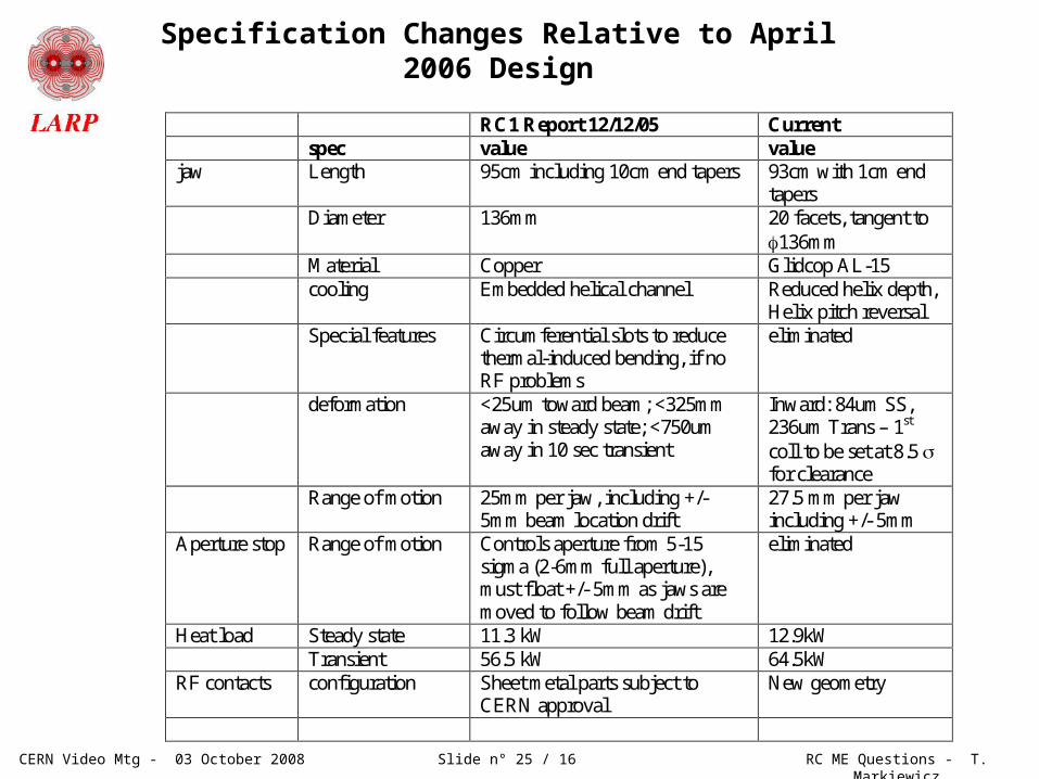
Specification Changes Relative to April 2006 Design
RC1 Report 12/12/05 Current spec value value jaw Length 95cm including 10cm end tapers 93cm with 1cm end
tapers Diameter 136mm 20 facets, tangent to
136mm Material Copper Glidcop AL-15 cooling Embedded helical channel Reduced helix depth,
Helix pitch reversal Special features Circumferential slots to reduce
thermal-induced bending, if no RF problems
eliminated
deformation <25um toward beam; <325mm away in steady state; <750um away in 10 sec transient
Inward: 84um SS, 236um Trans – 1st coll to be set at 8.5 s for clearance
Range of motion 25mm per jaw, including +/- 5mm beam location drift
27.5 mm per jaw including +/- 5mm
Aperture stop Range of motion Controls aperture from 5-15 sigma (2-6mm full aperture), must float +/- 5mm as jaws are moved to follow beam drift
eliminated
Heat load Steady state 11.3 kW 12.9kW Transient 56.5 kW 64.5kW RF contacts configuration Sheet metal parts subject to
CERN approval New geometry

CERN Video Mtg - 03 October 2008 RC ME Questions - T. MarkiewiczSlide n° 26 / 16
Beam 1
Beam 2
Primary collimators
First group ofsecondarycollimators
40 m
dipoles
IR-7

CERN Video Mtg - 03 October 2008 RC ME Questions - T. MarkiewiczSlide n° 27 / 16
Heat deposited in major components (W/m^3) in 1 hr beam lifetime operation
Component Units Upbeam Downbeam Stub shaft, aluminum W/m^3 6.5e3 52e3 Bearing, Si3N4 W/m^3 8.3e3 66.4e3 Image current bridge, aluminum W/m^3 150e3 400e3 Mo shaft (~const in z, concentrated in =120o) W 520 Jaw, Glidcop AL-15 (heat highly variable in z and ) kW 12.8

CERN Video Mtg - 03 October 2008 RC ME Questions - T. MarkiewiczSlide n° 28 / 16
Major jaw dimensions and calculated cooling performance
Component dimension units Jaw OD tangent to 20-faceted surface 136 mm Jaw OD to facet vertices 137.7 mm Jaw ID 66 mm Jaw length, including 10mm (in z) x 15o taper on each end 930 mm Mo Shaft OD 64 mm Mo Shaft ID 44 mm Hub length (centered) 150 mm Cooling tube OD x ID (square x square) 10 x 7 mm Embedded helix – center radius 80 mm Helix – number of turns ~47 - Cooling tube length – helix + entry + exit from vac tank ~16 m Flow per jaw 9 l/min Velocity 3 m/s Water temperature rise (SS 12.8 kW per jaw) 20.3 C Pressure drop 2.4 bar

CERN Video Mtg - 03 October 2008 RC ME Questions - T. MarkiewiczSlide n° 29 / 16
Vacuum Bake of 1st 200mm Test PieceResults: 4/1/07
~3x over LHC Spec
1st Jaw Braze Test Assembly has been vacuum baked at 300 degrees C for 32 hours.
•LHC Requirement = 1E-7 Pa = 7.5E-10 Torr•Baseline pressure of Vacuum Test Chamber:
4.3E-7 Pa (3.2E-9 Torr)•Pressure w/ 200mm Jaw Assy. in Test Chamber: 4.9E-7 Pa (3.7E-9 Torr)•Presumed pressure of 200mm lg. Jaw Assy.:
6.0E-8 Pa (4.5E-10 Torr)•Note: above readings were from gauges in the foreline, closer to the pump than to the Test Chamber. Pressures at the part could be higher.
Outcome:SLAC vacuum group has suggested longitudinal grooves be incorporated into the inner length of jaws; incorporated into next prototype

CERN Video Mtg - 03 October 2008 RC ME Questions - T. MarkiewiczSlide n° 30 / 16
Braze Test #3: 8 ¼-round jaws to mandrel/coil
19 June 2007: After 1st Jaw BrazePrepped for 2nd Braze to fillup jaw-jaw joints
14 June 2007: Jaw Fit Up

CERN Video Mtg - 03 October 2008 RC ME Questions - T. MarkiewiczSlide n° 31 / 16
Braze Test #3: Vacuum tests: No improvement
•3rd Jaw Braze Test Assembly has been vacuum baked at 300 degrees C for 32 hours. Results in slightly lower pressure.•Inclusion of longitudinal grooves in the inner length of jaws for better outgasing•Test Chamber setup similar to previous test.
Old New
Baseline 3.2E-9 Torr 2.4E-9 Torr??
w/ jaw assy. 3.7E-9 Torr 3.4E-9 Torr
Presumed jaw assy. pressure
4.5E-10 Torr 10E-10 Torr??
LHC requirement
7.5E-10 Torr 7.5E-10 Torr

CERN Video Mtg - 03 October 2008 RC ME Questions - T. MarkiewiczSlide n° 32 / 16
Exact Nature & Extent of Damaged Region
Thin Cu sample in FFTB electron beam at SLACHole = Beam Size
2000um 500 kW 20 GeV e- beam hitting a 30cm Cu block a few mm from edge for 1.3 sec (0.65 MJ)
FNAL Collimator with .5 MJ

CERN Video Mtg - 03 October 2008 RC ME Questions - T. MarkiewiczSlide n° 33 / 16
Cross Section at Shower Maximum Showing Copper Melting and Possible Fracture Regions in a Mis-steering Accident
CopperJaw
3D ANSYS model, E. Doyle
Melting zone (grey),radius = 3.3 mm
Fracture zone,radius = 7 mm
2.5 cm

CERN Video Mtg - 03 October 2008 RC ME Questions - T. MarkiewiczSlide n° 34 / 16
2.5 cm
Cross Section at Shower Maximum Showing Copper Boiling in a Mis-steering Accident
CopperJaw
3D ANSYS model, E. Doyle
Boiling zone (grey),radius = 2.2 mm