Embed Size (px)
Citation preview

2IREAPIREAP
Beam End Erosion and Induction Cell
Brian Beaudoin
06/23/08
Institute for Research in Electronics and Applied Physics

3IREAPIREAP
• Longitudinal stability of beams is important to prevent blow-up
• Designing a system to meet these specifications is already a challenge in itself
• Confine beam to a square pulse so we don’t fooltransverse measurements with an extracted beam that does not have the same current density.
Motivation

4IREAPIREAP
Outline
1. Induction focusing versus RF focusing.
2. UMER System overview, parameters and operating ranges.
3. End erosion of the beam as it circulates.
a. One-dimensional theory and the cusp point. b. MATLAB code for example end-erosion
calculations.
4. Induction cell and HV Modulator operation.
5. Ear-field focusing and timing involved in setting fields. Results and comparison to one-dimension model
5IREAPIREAP
RF Focusing vs. Induction Focusing
• In UMER, sinusoidal fields can not be used to
focus a square bunch.
• With RF focusing, self-fields of the beam can
distort the applied fields to the cavity
• For long pulses like in UMER, 100ns, need
very low frequency current sources to drive
an RF cavity, which means large cavities
6IREAPIREAP
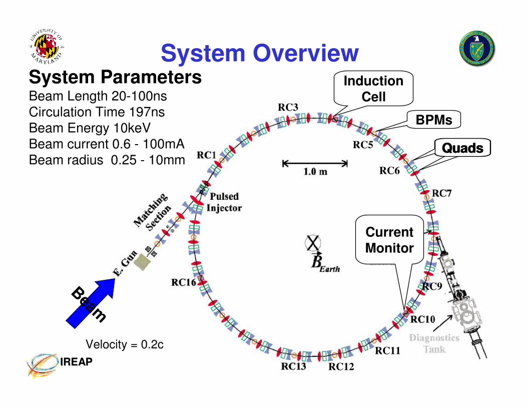
System Overview
Dipoles
Beam
RC3
RC5
RC6
RC9
RC11
RC12
Velocity = 0.2c
BPMs
QuadsQuads
Induction Cell
System ParametersBeam Length 20-100nsCirculation Time 197nsBeam Energy 10keVBeam current 0.6 - 100mABeam radius 0.25 - 10mm
Current Monitor

7IREAPIREAP
Beam-End Expansion and
1D Model
8IREAPIREAP
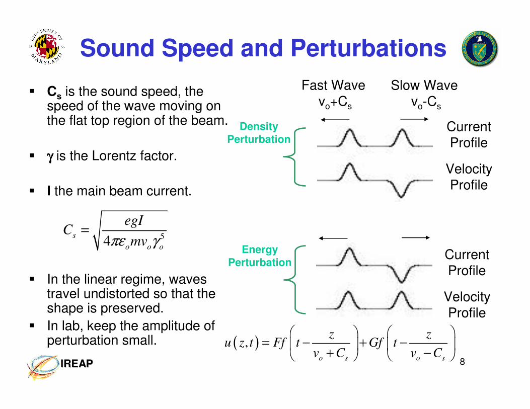
� Cs is the sound speed, the speed of the wave moving on the flat top region of the beam.
� γγγγ is the Lorentz factor.
� I the main beam current.
� In the linear regime, waves travel undistorted so that the shape is preserved.
� In lab, keep the amplitude of perturbation small.
Sound Speed and Perturbations
54
s
o o o
egIC
mvπε γ=
CurrentProfile
VelocityProfile
CurrentProfile
VelocityProfile
Fast Wave vo+Cs
Slow Wave vo-Cs
Density
Perturbation
Energy
Perturbation
( ),
o s o s
z zu z t Ff t Gf t
v C v C
= − + −
+ −

9IREAPIREAP
Geometry Factor
� g the geometry factor is a factor determined by the ratio of the beam size to pipe size.
� α α α α is a correction factor that is 0 for a space charge dominated beam, and 0.5 for an emittance dominated beam.
� Don’t forget if quads are running at reduced currents. What happens to beam size?
a b
PipeBeam
2lnb
ga
α
= +
-Kishek / O’Shea class notes and Reiser’s Book 1st ed. p.505

10IREAPIREAP
Longitudinal Expansion
• Cusp Point
– As Beam circulates in the lattice, the head and tail will eventually touch each other.
• Head/Tail Energy
– Head will accelerate from
the main beam at a ∆E and tail will decelerate at the same amount.
Velocity Profile
Cusp
Main Beam Velocity
∆v
∆v
Head
Tail
vo vo
Min Width
Max Width
Lin
e c
harg
e d
en
sit
y
Time

11IREAPIREAP
Cusp Point
-Wang D. X. PhD Thesis, “Experimental Studies of Longitudinal Dynamics of Space-Charge Dominated Electron Beams", 1993
z = 0 z
ττττo
Initial Beam
vo
Reduction in linecharge density
vo
t< τ< τ< τ< τo
Cusp
t= τ= τ= τ= τo
Turn n Turn n + 1

12IREAPIREAP
1D MATLAB Code to Study End-Erosion
Important Part of Code
Vary Parameters and
see what happens
Parameters to Vary
Energy,
Current,
Beam Length

13IREAPIREAP
M-File Output
Velocity Profile
Current Profile

14IREAPIREAP
M-File Output
Simulation of Multi-Turn
Invalid past “simple wave regime”

15IREAPIREAP
My 1-D CalculationsFor 7mA Beam measured at RC10
( )2s o s
E mC v C∆ = +
• Initial beam length when formed is 5.93m.
• The rate of expansion for the 7mA beam is 5.5nsec / Turn, assuming no loss in current. So that by the 9th turn, the beam head and tail are touching each other, for 83% quads.
∆E = 549eV

16IREAPIREAP
Induction Cell
17IREAPIREAP
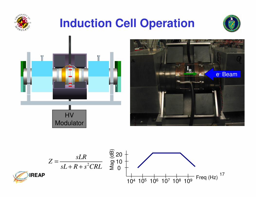
Induction Cell Operation
E�
HV Modulator
IRe- Beam
2
sLRZ
sL R s CRL=
+ +
109
010
20
Mag (
dB
)
104 105 107Freq (Hz)
106 108

18IREAPIREAP
Multiple Cells and Orientations
Beam
Beam
BeamSingle Core
Cell
Two Cells back to back
Dual Core Cell
Beam
Double Core Cell
Wire
19IREAPIREAP
Bs of CMD5005
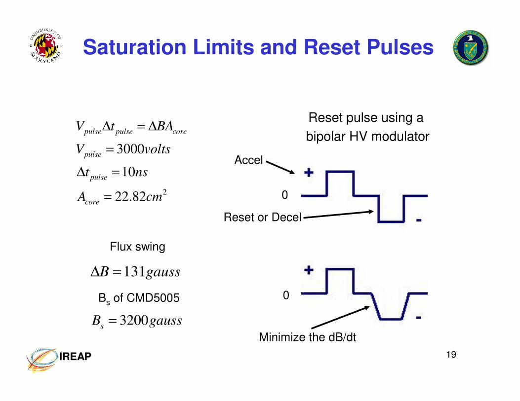
Saturation Limits and Reset Pulses
2
3000
10
22.82
pulse pulse core
pulse
pulse
core
V t BA
V volts
t ns
A cm
∆ = ∆
=
∆ =
=
131B gauss∆ =
3200s
B gauss=
Flux swing
Reset pulse using a
bipolar HV modulator
0
Minimize the dB/dt
0
Accel
Reset or Decel

20IREAPIREAP
High Voltage Modulator
• Pulse fields have a fixed on-time of 10-15nsec with a FWHM of ~8nsec.
• Fields are purely composed of fixed rise times so ∆t can not be changed for this pulser.
• Amplitude can vary from 0 – 3kV.
• Both positive and negative pulses must be “on” to reset the core.
Error will
show up
later
Beam Bunch
Energy Storage
Energy Storage
BehlkeSwitch
BehlkeSwitch Load

21IREAPIREAP
Longitudinal Focusing

22IREAPIREAP
Focusing Experiment
RC10
Current
Monitor
RC4
Induction
Cell
Time
Gap V
oltage (
volts)
0
100ns
� The compensation voltage is set
based on the one dimensional
longitudinal expansion calculations for
a rectangular bunch.
� Ear-fields are applied for a single turn.
� Pencil Beam = 176eV
Time
Curr
ent
Max Width
Min
Width