Embed Size (px)
Citation preview

RESEARCH Open Access
Beacon routing algorithm in wireless sensornetworks with mobile gatewayJun Xia1,2*, Fei Yin3, Yun Rui4,2,1, Kai Yu1, Zhenhong Li3, Haifeng Wang3 and Zhiyong Bu1
Abstract
In this article, we first propose a reverse sector mechanism and an optimization division mechanism, which canprovide enormous energy conservation benefits. Based on these mechanisms, an efficient sensory data collectionmechanism over a cellular-WSN integrated network, named beacon routing algorithm, is proposed tospontaneously renew the local WSN topology according to the position of the UE relative to the location of thebeacon cluster under an optimized network division pre-set. Different from the previous studies, beacon routingalgorithm achieves the adaptive topology renewal without additional re-clustering overhead. Through performanceevaluation, we can implement WSN by making a trade-off between network scale and sector division. Moreover,optimal energy efficiency can be obtained in each divided sub-network; therefore, the WSN lifetime can beincreased significantly and the data collection efficiency will be enhanced. Simulation results are presented to showthe performance of the proposed algorithm.
Keywords: wireless sensor network (WSN), user equipment (UE), gateway, beacon, routing
1. IntroductionInformation sharing between different types of networkentities drives the aggregation of heterogeneous net-works. This kind of aggregation provides for examplethe possibility to exchange information between entitiesof a local network and a heterogeneous network. A spe-cific scenario for a combination of capabilities of differ-ent networks for information sharing is to use a cellularnetwork element such as a user equipment (UE) orentity as a gateway for local wireless sensor networks(WSNs). That is, elements of a cellular network and aWSN are mixed in order to easily expand the functionof each network. With the natural mobility characteris-tic, this new type of multimode UE equipped with WSNmodule is similar to an enhanced type of mobile sensornode with more energy and flexibility. Since WSN canbe deployed easily as less infrastructure and attentionare required, the integration of cellular network andWSN seems attractive by combining the sensing partand the connection part in a flexible way, which
expands both networks’ scalability and ubiquitous ser-vice applications.In this article, we assume a type of isolated sensor net-
work and a special sink, eNB, which solve the contradic-tion between the UE and the sink in terms offunctionality in convergent scenario. Each UE can play arole of information collector. Since the quantity of UE ishuge, it is possible to fully utilize this advantage to col-lect overall sensory data, enhance network transmissionefficiency, and increase lifetime of sensor networks.However, as the positions of UEs are random; it is hardfor a single UE to collect full information of local WSNwith high efficiency. Hence, the traditional topology androuting algorithm used in WSN are hard to meet thecollecting efficiency as UEs appear in different positions.For example, it has been suggested to optimize theselection of cluster heads under specific constraints.However, there are still open issues on how to solveproblems related to the computation and communica-tion overheads incurred by re-clustering caused by thestochastic nature of UEs.WSN is subject to a unique set of resource con-
straints, such as finite on-board battery power and lim-ited network communication bandwidth. It is wellknown that communicating 1 bit over the wireless
* Correspondence: [email protected] Institute of Micro-system and Information Technology (SIMIT),Chinese Academy of Sciences (CAS), Shanghai, ChinaFull list of author information is available at the end of the article
Xia et al. EURASIP Journal on Wireless Communications and Networking 2012, 2012:86http://jwcn.eurasipjournals.com/content/2012/1/86
© 2012 Xia et al; licensee Springer. This is an Open Access article distributed under the terms of the Creative Commons AttributionLicense (http://creativecommons.org/licenses/by/2.0), which permits unrestricted use, distribution, and reproduction in any medium,provided the original work is properly cited.

medium at short ranges consumes far more energy thanprocessing that bit. In conventional routing protocols,sensor nodes make the routing decision via collectingrouting information in delivery package and followingthe rule of specific routing algorithm. Additional routingdata exchange between sensor nodes will obviously leadto the network inefficiency and unnecessary energywaste. Thus, we endeavour on turning routing commu-nication procedure into calculation of local sensor nodeand propose beacon routing algorithm to eliminatecommunication consumption in routing exchangingprocess. Sensor nodes in local network can autono-mously make routing decision in an efficient wayaccording to the polling signal containing beacon clusteridentification from mobile gateway. Therefore, additionalcost of routing message exchange can be saved toincrease the network lifetime.The rest of this article is organized as follows. Section
2 introduces some related studies and discusses the pro-blem. Section 3 presents the beacon routing algorithmin more details, including reverse sector topologymethod, divided sector optimization, and an implemen-tation example by adopting proposed beacon routingalgorithm over a cellular-WSN integrated network. InSection 4, we present our simulation results on the pro-posed algorithm. Finally, we conclude this article in Sec-tion 5.
2. Related studiesIn a conventional WSN, sink is a local device for col-lecting data of the whole network. But the data collect-ing efficiency is low for a fixed sink unless a number ofsinks are deployed, which actually divides the local net-work into several parts. One sink can communicate withother sinks via internet for the purpose of sharing infor-mation. Perhaps the most profound difference betweensensor networks and other types of networks, wired orwireless, comes from the fact that the classical separa-tion of address and content in a packet is no longerviable in the sensor net setting [1,2].In WSNs, dense networks of distributed communicat-
ing sensors can improve signal-to-noise ratio by redu-cing average distances from sensors to the source ofsignal, or target. Increased energy efficiency in commu-nications is enabled by the multi-hop topology of thenetwork [3]. A solution to the localization problem canspecify a set of sensor nodes on a path that gather andcombine data as they route the result back to the query-ing node. Conventional protocols, for example floodingor gossiping-based routing [4], waste energy and band-width to transfer extra and unnecessary copies of datain overlapping areas. In some hierarchical topologybased sensor networks, each cluster elects a cluster-headnode, and routing is done only among the cluster-heads
(the remaining nodes always route packets through theircluster-heads) [5]. This is advantageous for a variety ofreasons, including the possibility of using simpler com-munication protocols within a cluster, recycling ofresources (such as frequency assignments) among dis-joint clusters, and saving power. The focus of the exist-ing literature has mostly concentrated on optimizing thechoices of cluster heads to meet some constraints. How-ever, fewer studies have been devoted on how to allevi-ate the computation and communication overheadscaused by re-clustering that spurs the development of agateway node for a WSN.Mobile sink WSN (MSWSN) is similar to the scenario
described in Section 1, since UEs actually serve asmobile sink with random mobility in local WSN. Nonetwork information is required as the decision of asink to decide next sojourn position is random. Themovement pattern of a sink does not depend upon net-work conditions, which may not lead to optimal net-work lifetimes. Random mobility requires continuoussink position updates and route reconstruction, whichwill increase the transceiver burden of each sensornodes.Flooding is an easy routing protocol [6,7], in which
each node only needs to broadcast the newly receivedmessage to its neighbouring nodes, not requiring topol-ogy records or large amount of analyses. This routingprotocol is reliable. Regardless of any changes in thenetwork, data can be transmitted to the sink node inthe way of flooding as long as the path between thesource node and the sink node exists. But flooding con-sumes much energy, because for each data packet, allnodes in the broadcast domain will receive the packetand forward it to its neighbours. The large amount ofpower required by flooding causes a prohibitively shortnetwork lifetime, which makes it difficult to apply basicflooding protocol to real WSNs.Gossiping [4] is an alternative to the classic flooding
approach that uses randomization to conserve energy.Instead of indiscriminately forwarding data to all itsneighbours, a gossiping node only forwards data on toone randomly selected neighbour. If a gossiping nodereceives data from a given neighbour, it can forwarddata back to that neighbour if it randomly selects thatneighbour. Whenever data travel to a node with highdegree in a classic flooding network, more copies of thedata start floating around the network. At some point,however, these copies may end up imploding. Gossipingavoids such implosion because it only makes one copyof each message at any node. The fewer copies it made,the lower the likelihood that any of these copies willever implode. Although gossiping largely avoids implo-sion, it does not solve the overlap problem as a gossip-ing node receives data from a given neighbour, it can
Xia et al. EURASIP Journal on Wireless Communications and Networking 2012, 2012:86http://jwcn.eurasipjournals.com/content/2012/1/86
Page 2 of 15

forward data back to that neighbour if it randomlyselects that neighbour. In addition, the gossipingapproach does not solve the sink mobility problem.Data centric routing mechanisms such as directed dif-
fusion [8] conduct routing is similar to AODV in adhoc network, routing request and reply are necessaryduring the period of path establishment. Path discoverydepends on the exchange of inquiring packet among dif-ferent nodes in network. This kind of routing mechan-ism performs better than simple flooding algorithms,but it still relies on basic flooding mechanism duringthe period of path discovery. Some protocols considerthe classical flooding as the basic approach in MSWSNfor initializing network and packet delivery. ART Proto-col [9] proposed an adaptive reversal tree-based algo-rithm. A tree directed towards sink assigned temporaryroot node is created. This is achieved through initialflooding. Source nodes use this tree to direct datareports towards root node which then delivers data tothe sink. ART efficient path repair mechanism reducessink’s communication overhead but may result in sub-optimal source to sink path. ALURP and LURP are pro-posed in [10] that include a geographic datadissemination approach. In LURP, sink initially floodsits location information plus a virtual circular area (VC)centred on its current position. Then, as long as sinkmobility is confined in VC, local broadcast is performed.Exit from VC requires global flooding. Nodes outsideVC use geographic routing to route data towards sink.Once packet arrives inside VC, shortest path routing isused on sink updated paths. In ALURP, radius of VC isadapted according to the mobility of the sink. Thisreduces local broadcast cost. In addition, numbers ofglobal flooding requirements are also reduced as VCsize can be dynamically changed.Complete Graph-based Clustering Algorithm (CGCA)
[11] is proposed in a densely deployed sensor network.CGCA divides the network into a few complete graphs;each complete graph independently becomes a cluster.CGCA introduces mobile nodes as gateways and verifiesits efficiency in lengthening lifetime of WSN. However,the algorithm imposes some restriction on the behaviourof the mobile gateway, such as roaming around thedeployment region, which is unnecessary as more effi-cient and flexible schemes can be proposed.The discussion about integration of heterogeneous
network is very prevalent, but the content about WSNand cellular is scarce. The routing algorithms and topol-ogy control methods described above may be used tosolve the problems in each specific scenario, but theycannot be applied in the scenario we suggested in Sec-tion 1 straightforwardly. The traditional sink as well asmobile sink are different from UE in terms of
distribution density, transmission capability, mobilityrandomness, etc.
3. Beacon cluster routing algorithmSensor networks extend the existing internet deep intothe physical environment. A WSN for a local sensornetwork may consist of spatially distributed autonomoussensors which are configured to monitor different para-meters, such as physical or environmental conditionslike temperature, sound, pressure, movements, concen-trations of specific elements in the air, etc. Each nodeequipped with one or more sensing devices such asacoustic microphone arrays, video or still cameras, infra-red, seismic, or magnetic sensors. The sensor nodes arefurther configured to cooperatively pass data through anetwork to a main location which is also referred to assink. Also bi-directional communication between thesensor nodes and the sink is possible in order to enablea control of the sensors. WSNs are used, for example, inmany industrial and consumer applications, such asindustrial process monitoring and control, machinehealth monitoring, environment and habitat monitoring,healthcare applications, traffic control, etc. The nodes ofthe WSN may comprise sensor nodes (SNs) and one ormore cluster head (CH) nodes. Cluster-head nodes areused as managing nodes when a WSN is divided intoone or more clusters containing plural sensor nodes andone cluster head node. The sensor nodes are connectedto one (or sometimes several) other sensor nodes,wherein their data are forwarded to a respective clusterhead which transmit the aggregated information to thesink. A sensor node has typically several parts: a trans-ceiver with an antenna or connection to an antenna, amicrocontroller, an electronic circuit for interfacing withthe sensors and an energy source, e.g. a battery or anembedded form of energy harvesting. The topology of aWSN can vary from a simple star shape to a multi-hopmesh network.The largest design constraint, however, is the limited
energy budget of a sensor node together with therequirement of long network runtimes. For instance,having a node continuously powered on drains an AAbattery of 3000 mAh in about 4 days [12], which is wellbelow the typically required decade of operation. On theother extreme, even if a node is switched off all thetime, inherent current leakages in the battery limits thebattery lifetime to 10-15 years in dependency of theoperating temperature. This renders network lifetimemaximization with battery-powered nodes useless if thelifespan goes beyond this number [13]. In typical sensorapplications, the energy consumption is dominated bythe node’s radio consumption. A prominent example ofthe current non-optimized WSN deployment is that the
Xia et al. EURASIP Journal on Wireless Communications and Networking 2012, 2012:86http://jwcn.eurasipjournals.com/content/2012/1/86
Page 3 of 15
start-up alone costs the network a third of its batterypower [13,14]. Based on these constraints for WSN,high efficient network implementation scheme and datacollection under power saving mode is essential forpractical applications.
3.1. AssumptionsGenerally, the coverage of WSN can be approximatelyconsidered as a circular region. For energy efficiencyconsideration, local sink is inclined to be implementedin the middle of the coverage region. Thus, we candivide the circular region into sectors by slicing theregion from the centre of the circle. The following ana-lysis is based on this basic geometry. In this model, weignore all radio propagation effects such as obstacle ormultipath interference, anisotropy or asymmetry oftransmission, etc. We assume all nodes have the sametransmission range which is set to be equal to r orrescaled if necessary. To make it easy for analysis, wefurther assume the following:• Each sensor node is homogeneous. Local sensor net-
work is implemented as flat with a unique sink node.• Index number i denotes the layer sequence of the
divided sector layer; similarly, index number j denotesthe block sequence of the divided mini sector whichrepresents the divided piece of each layer in the sector.• The radius of the sector is R, and the transmission
range of each sensor node is r.• The primary energy consumption of each transmis-
sion or reception is approximate to the same basicenergy unit Eb.• The vertex angle of sector is set as b; and density of
sensor node distributed in the sector is represented by r.• Energy consumption of the primary mini sector is
specified as Eij.• Chain type network is considered as the basic net-
work model in the following analysis, in which energyconsumption can be represented as Echain, each sensornode in the chain consumes Esent energy units to trans-mit data and Ereactive energy units to receive data.• Energy consumption of the whole sector is specified
as Esec, and for the reverse topology sector case is Ersec.• Energy consumption of network flow inside the sector
layer is denoted as Eintra, which represents the wholeenergy consumption of total mini sectors in the same layer.• Energy consumption of network flow between the
sector layers is denoted as Einter, which represents theenergy consumption between each divided layers.
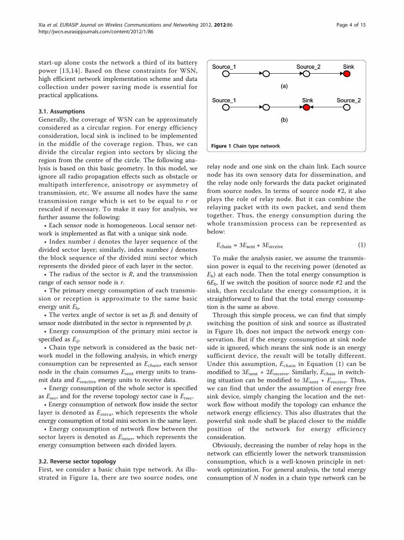
3.2. Reverse sector topologyFirst, we consider a basic chain type network. As illu-strated in Figure 1a, there are two source nodes, one
relay node and one sink on the chain link. Each sourcenode has its own sensory data for dissemination, andthe relay node only forwards the data packet originatedfrom source nodes. In terms of source node #2, it alsoplays the role of relay node. But it can combine therelaying packet with its own packet, and send themtogether. Thus, the energy consumption during thewhole transmission process can be represented asbelow:
Echain = 3Esent + 3Ereceive (1)
To make the analysis easier, we assume the transmis-sion power is equal to the receiving power (denoted asEb) at each node. Then the total energy consumption is6Eb. If we switch the position of source node #2 and thesink, then recalculate the energy consumption, it isstraightforward to find that the total energy consump-tion is the same as above.Through this simple process, we can find that simply
switching the position of sink and source as illustratedin Figure 1b, does not impact the network energy con-servation. But if the energy consumption at sink nodeside is ignored, which means the sink node is an energysufficient device, the result will be totally different.Under this assumption, Echain in Equation (1) can bemodified to 3Esent + 2Ereceive. Similarly, Echain in switch-ing situation can be modified to 3Esent + Ereceive. Thus,we can find that under the assumption of energy freesink device, simply changing the location and the net-work flow without modify the topology can enhance thenetwork energy efficiency. This also illustrates that thepowerful sink node shall be placed closer to the middleposition of the network for energy efficiencyconsideration.Obviously, decreasing the number of relay hops in the
network can efficiently lower the network transmissionconsumption, which is a well-known principle in net-work optimization. For general analysis, the total energyconsumption of N nodes in a chain type network can be
Figure 1 Chain type network.
Xia et al. EURASIP Journal on Wireless Communications and Networking 2012, 2012:86http://jwcn.eurasipjournals.com/content/2012/1/86
Page 4 of 15

concluded as a transmission with N - 1 hops and recep-tion energy consumption is
Echain = (N − 1) (Esent + Ereceive) (2)
As described in [15], transmit power consumption ofsensor node is similar to the receive power consump-tion. Thus, we can still use the prior assumption thatthe basic energy consumption unit is Eb. According tothis assumption, the total energy consumption of thechain topology can be calculated as
Echain = 2Eb (N − 1) (3)
Based on this, each sector in the sector topology ispart of the round region and covered by a sink. Asshown in Figures 2 and 3, a sector is divided into ⌈R/r⌉layers according to one-hop transmission range. Layercloser to the sink possesses the higher forwarding bur-den, which is called high layer. The layer far from thesink can be defined as lower layer as its forwarding fre-quency is lower.As illustrated in Figure 2, the sink node is closer to
the vertex of sector. There is a high probability of inter-mediate sensor nodes to keep active status for forward-ing data packets from its child nodes. Intermediatenodes that are closer to the sink consume more energyfor forwarding even itself has no sensory data needs toreport. In other words, if fewer hops exist in one pathfrom lower layer node to sink or less number of lowerlayer nodes in the path, forwarding frequency of inter-mediate nodes can be significant lower, as illustrated inFigure 3. In this case, the positions of the sink andsource are reversed. The maximum hop in reverse sec-tor can be estimated as max {⌈bR/2r⌉-1, ⌈R/r⌉-1}. Evenb/2 ≤ 1, the maximum number of hops in reverse sector
topology is still lower than in the normal case, thus theenergy burden of the whole sector in reverse sectortopology is also lower than in the normal case.Below we try to analyse the sector topology energy
model. Assume the sensor networks located in the sec-tor are referred as the complete binary tree topology, itis easy to find there are 2i-1 chain links flowing to thesink in layer i. Each chain flow possesses (i-1) hops tothe sink. Substitute the parameter in Equation (3); wecan get the total energy consumption of sector shown inFigure 2 as
Esec =�R/r�∑
i=1
2Eb · 2i−1 (i− 1)
= Eb
[(⌈R/
r⌉− 2
)2�R/r�+1 + 4
] (4)
Similarly, for the reverse sector topology, we can alsorepresent the network energy consumption with basicchain flow energy model. Then the flow of each layer tothe sink may consist of two types of chain flows, whichare the inter layer flows and intra layer flows. The interlayer flows include all the vertical chains in Figure 3. Tomake it easy for calculation, we can stochastically pick asingle sensor in each layer to consist the inter layerflow. Thus, the intra layer flows consist of all the chainflows that exist in each single layer and each node prefertransmit data to the node nearby in the same layer.Here the total energy consumption can be estimated as
Ersec = Einter + Eintra
=
⎧⎨⎩�R/r�∑
i=1
2Eb (i− 1)
⎫⎬⎭
inter
+
⎧⎨⎩�R/r�∑
i=1
�(i−1/2)β�∑j=1
2Eb ·(j− 1
) · 2i−1⌈(i− 1
/2)β⌉⎫⎬⎭
intra
= Eb ·�R/r�∑
i=1
{2 (i− 1) + 2i−1 ·
[⌈(i− 1/
2)
β⌉− 1
]}
≤ Eb ·{
2�R/r�(⌈
R/
r⌉
β − 32
β
)+⌈R/
r⌉2 − ⌈
R/
r⌉
+12
β + 1}
(5)
Figure 2 sector topology.
Figure 3 Reverse sector topology.
Xia et al. EURASIP Journal on Wireless Communications and Networking 2012, 2012:86http://jwcn.eurasipjournals.com/content/2012/1/86
Page 5 of 15

The energy consumption in normal case and reversecase can be compared as follows:
Egain = Esec − Ersec
≥ Eb
[(⌈R/
r⌉− 2
)2�R/r�+1 + 4
]− Eb ·
{2�R/r�
(⌈R/
r⌉
β − 32
β
)+(⌈
R/
r⌉)2 − ⌈
R/
r⌉
+12
β + 1}
= Eb ·{
2�R/r� ·(
2⌈R/
r⌉− β
⌈R/
r⌉
+32
β − 4)− (⌈
R/
r⌉)2 +
⌈R/
r⌉− 1
2β + 3
} (6)
We substitute ⌈R/r⌉ as M, which can be defined asnetwork scale here. Thus, inequality (6) can be rewriteas
Egain ≥ Eb ·{
2M ·(
2M− βM +32
β − 4)−M2 + M− 1
2β + 3
}(7)
From inequality (7), it is easy to see that the inequalityis consisted by an exponential part and a parabola part.The exponential part actually determines the Egain, withthe increasing of parameter M. Egain tends to be amonotonic increase function with the growth of M. As aconclusion, through simple network flow reverse opera-tion, energy cost reservation can be achieved especiallyin large scale network.
3.3. Divided sector optimizationA well-known wireless network capacity obtained byGupta and Kumar states that the per node throughput
scales as 1/√n . In other words, it goes to zeros as the
number of nodes N in a wireless ad hoc networkincreases [16]. As the number of nodes increases, everynode spends almost all of its time forwarding packets ofthe other nodes. On the basis of this theory, the scale oflocal sensor network needs to be maintained in smallsize in order to guarantee the throughput. On the otherhand, if we divide the local sensor network into severalparts, the scale of the network is reduced while thethroughput of each part is enhanced accordingly. Thisidea drives us to optimize the division process.In binary tree topology analysis, we find that it is pos-
sible to optimize the local sensor network energy effi-ciency by making a trade-off between parameters M andb. Similar to the ordinary sector performance, node den-sity is ignored which may deteriorate network perfor-mance gradually in the reverse sector topology. For thisreason, we analyse the general tree topology situationwithout specific topology. Assuming the sensor node isscattered in the sector region uniformly distributed. Thedensity of the sensor nodes within each square meter isr. Hence, number of nodes in each layer is
N =(2i− 1)
2βρr2 (8)
Similar to the above case in binary tree topology, net-work flows in the general sector topology can still beconsidered as the combination of chain flow originatedfrom each node to the sink. Total energy consumption
of the sector can be calculated as
Esec =�R/r�∑
i=1
2Ebβρr2 (2i− 1)
2(i− 1)
=Ebβρr2
6
⌈R/
r⌉ (
4⌈R/
r⌉
+ 1) (⌈
R/
r⌉− 1
)(9)
In Equation (9), sector energy consumption Esec varieswith vertex angle b and the nodes density r. Comparingwith Equation (4), the energy consumption of the sectortype network is degraded from the exponential growthto the power function growth, which is reasonable inpractical scenario. As in the hierarchical network, depthof the network should not be set too large for sensornode lifetime consideration. With the increase of net-work depth, possibility of intermediate nodes out oforder rises accordingly. Especially in large scale sensornetwork, exponential model of energy consumption isobviously unacceptable in practical implementation.After obtaining the energy consumption in the normal
case, we need to estimate the expenditure in reversecase. Similarly, network flows can be categorized asinter sector and intra sector parts, which possess thesame meaning as in the binary tree topology analysis, i.e.
Ersec = Einter + Eintra
=
⎧⎨⎩�R/r�∑
i=1
2Eb (i− 1)
(i− 1
/2)βρr2(
i− 1/
2)β
⎫⎬⎭
inter
+
⎧⎨⎩�R/r�∑
i=1
�(i−1/2)β�∑j=1
2Eb ·(j− 1
) ·(i− 1
/2)βρr2(
i− 1/
2)β
⎫⎬⎭
intra
=�R/r�∑
i=1
2Ebρr2 (i− 1) +�R/r�∑
i=1
�(i−1/2)β�∑j=1
2Eb ·(j− 1
) · ρr2
= 2Ebρr2 ·�R/r�∑
i=1
[(i− 1) +
12
(⌈(i− 1
/2)β⌉− 1
) ⌈(i− 1
/2)β⌉]
≤ 2Ebρr2 ·�R/r�∑
i=1
{(i− 1) +
12
[(i− 1
/2)β + 1
] (i− 1
/2)β
}
= Ebρr2 ⌈R/
r⌉{
13
β2⌈R/
r⌉2
+(
12
β + 1)⌈
R/
r⌉− 1
12β2 − 1
}
(10)
In Equation (10), if we consider ⌈R/r⌉ as an indepen-dent variable of function Ersec, the core part of theabove function can be approximated as a quadraticfunction. Comparing the energy consumption of normalcase and reverse case, the energy saved after the reverseprocess can be obtained as
Egain = Esec − Ersec
≥ Ebβρr2
6
⌈R/
r⌉ (
4⌈R/
r⌉
+ 1) (⌈
R/
r⌉− 1
)
− Ebρr2 ⌈R/
r⌉ {
13
β2⌈R/
r⌉2
+(
12
β + 1)⌈
R/
r⌉− 1
12β2 − 1
}
= Ebρr2 ⌈R/
r⌉{
13
β (2− β)⌈R/
r⌉2 − (1 + β)
⌈R/
r⌉
+1
12β2 − 1
6β + 1
}(11)
Rewritten the inequality (11) into inequality (12) basedon parameter b, we get
Egain ≥ Ebρr2 ⌈R/
r⌉{(
112− 1
3
⌈R/
r⌉2
)β2 +
(23
⌈R/
r⌉2 − ⌈
R/
r⌉− 1
6
)β − ⌈
R/
r⌉
+ 1}
(12)
In order to find the maximum value of Egain, we takethe derivative of Egain with respect to b, and impose thederivation equal to 0
Xia et al. EURASIP Journal on Wireless Communications and Networking 2012, 2012:86http://jwcn.eurasipjournals.com/content/2012/1/86
Page 6 of 15

dEgain
dβ=
(16− 2
3
⌈R/
r⌉2
)β +
23
⌈R/
r⌉2 − ⌈
R/
r⌉− 1
6= 0 (13)
Obviously, we get b when Emax_gain achieves the maxi-mum
β = 1− 6⌈R/
r⌉
(4⌈R/
r⌉2 − 1
) (14)
If ⌈R/r⌉ grows large enough, then we can get the lim-itation of b:
lim�R/r�→+∞β = 1 (15)
According to the optimized parameter b, we can getthe max energy gain as
Emax gain = Ebρr2 ⌈R/
r⌉(
13
⌈R/
r⌉2 − 2
⌈R/
r⌉
+1112
)(16)
From the above results, the maximum energy gain canbe achieved depending on the vertex angle of thedivided sector in the circular region. But in practicalapplications, implementation complexity and expendi-ture cannot be ignored, which may constraint the num-ber of divisions. In these practical cases, we may have togive up the optimal scheme, choose the sub-optimaldivision number. By dividing Equation (12) with Equa-tion (9), we can get the energy gain efficient function asfollows.
Eefficient =Egain
Esec≥
2β (2− β)⌈R/
r⌉2 − 6 (1 + β)
⌈R/
r⌉
+12
β2 − β + 6
β(4⌈R/
r⌉
+ 1) (⌈
R/
r⌉− 1
) (17)
If we consider ⌈R/r⌉ as the variable in Equation (17),we can get the limitation of Eefficient:
lim�R/r�→+∞Eefficient = 1− β
2(18)
Equation (18) shows that Eefficient increases when bdecreases. In reality, when the scale of the networkgrows, smaller b keeps the network more efficient interms of energy. In the case that the value of b is low,which means the reverse section operation will bringmore energy conservation for small sector network, themaximum gain of the reverse section cannot beachieved. The trade-off between energy efficiency andenergy gain needs to be carefully considered during thepractical implementation.
3.4. Beacon routing algorithm implementationSince we can pre-implement local sensor networkaccording to the optimal division described above, bea-con routing algorithm based on these divided sectors
can be achieved. The beacon routing algorithm is amethod of pre-computation based on divided sectormodel to aid the routing.We assume the pre-deployed WSN network is seg-
mented into multiple sectors without sink and eachgroup has one cluster head to minimize the power con-sumption and increase the WSN lifetime, i.e., most ofnodes are in sleep mode and only the cluster heads bea-cons regularly for the purpose of providing basic WSNinformation. Each cluster with its cluster head is identi-fied by the unique id (namely the beacon cluster id) andeach cluster is named as beacon cluster.We make some important assumptions as follows:• The topology of sensor network is semi-static.• UE as mobile gateway for collecting local sensor net-
work data is also semi-static during the data collectingperiod.• UE possess the capability to directly notify every
sensor node its up-to-date information via broadcasting.• Cluster division and cluster-head selection are pre-
defined during the network implementation period.Once a UE starts to collect WSN information and
access the WSN beacon cluster head, it senses the bea-con transmission by beacon cluster head in WSN, col-lects the synchronization information, signal strength aswell as local beacon cluster information. Then the UEsreport the accessing request to the eNB who selects theUE gateway among UEs nearby the beacon cluster andallocate broadcasting sequence of each UE. The selectedUEs trigger the cluster head and awake all WSN nodesin the network, broadcast topology update notificationto inform sensor nodes to change their network flowdirection. Before a UE updates the location informationstored in sensor nodes, it should activate sensor nodesvia preamble sample technique [17-19]. Each sensornode with pre-defined routing table changes the net-work flow direction correspondingly. This ensures thatthe whole WSN information can be collected by themobile gateway in an efficient way.Initialization configuration of beacon cluster is essen-
tial for the local sensor network. Once an eNB or UEneeds to collect WSN information, some UEs will beselected to serve as mobile gateways. Figure 4 shows aWSN segmented into six groups with six cluster headsas an example.Cluster head of each beacon cluster initializes a flood-
ing procedure to pre-configure the routing table of eachsensor node in the network. Intermediate nodes receivethe flooding packet and modify the hop count by addingthe current hop. According to the reception sequence ofthe flooding packet from each beacon cluster, intermedi-ate nodes maintain a routing table with the parametersconsisted of beacon cluster number, accumulated hop
Xia et al. EURASIP Journal on Wireless Communications and Networking 2012, 2012:86http://jwcn.eurasipjournals.com/content/2012/1/86
Page 7 of 15
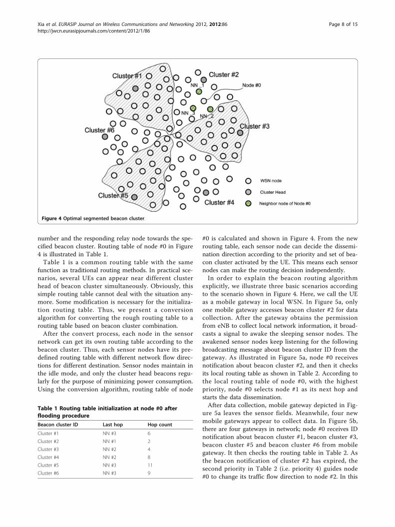
number and the responding relay node towards the spe-cified beacon cluster. Routing table of node #0 in Figure4 is illustrated in Table 1.Table 1 is a common routing table with the same
function as traditional routing methods. In practical sce-narios, several UEs can appear near different clusterhead of beacon cluster simultaneously. Obviously, thissimple routing table cannot deal with the situation any-more. Some modification is necessary for the initializa-tion routing table. Thus, we present a conversionalgorithm for converting the rough routing table to arouting table based on beacon cluster combination.After the convert process, each node in the sensor
network can get its own routing table according to thebeacon cluster. Thus, each sensor nodes have its pre-defined routing table with different network flow direc-tions for different destination. Sensor nodes maintain inthe idle mode, and only the cluster head beacons regu-larly for the purpose of minimizing power consumption.Using the conversion algorithm, routing table of node
#0 is calculated and shown in Figure 4. From the newrouting table, each sensor node can decide the dissemi-nation direction according to the priority and set of bea-con cluster activated by the UE. This means each sensornodes can make the routing decision independently.In order to explain the beacon routing algorithm
explicitly, we illustrate three basic scenarios accordingto the scenario shown in Figure 4. Here, we call the UEas a mobile gateway in local WSN. In Figure 5a, onlyone mobile gateway accesses beacon cluster #2 for datacollection. After the gateway obtains the permissionfrom eNB to collect local network information, it broad-casts a signal to awake the sleeping sensor nodes. Theawakened sensor nodes keep listening for the followingbroadcasting message about beacon cluster ID from thegateway. As illustrated in Figure 5a, node #0 receivesnotification about beacon cluster #2, and then it checksits local routing table as shown in Table 2. According tothe local routing table of node #0, with the highestpriority, node #0 selects node #1 as its next hop andstarts the data dissemination.After data collection, mobile gateway depicted in Fig-
ure 5a leaves the sensor fields. Meanwhile, four newmobile gateways appear to collect data. In Figure 5b,there are four gateways in network; node #0 receives IDnotification about beacon cluster #1, beacon cluster #3,beacon cluster #5 and beacon cluster #6 from mobilegateway. It then checks the routing table in Table 2. Asthe beacon notification of cluster #2 has expired, thesecond priority in Table 2 (i.e. priority 4) guides node#0 to change its traffic flow direction to node #2. In this
Figure 4 Optimal segmented beacon cluster.
Table 1 Routing table initialization at node #0 afterflooding procedure
Beacon cluster ID Last hop Hop count
Cluster #1 NN #3 6
Cluster #2 NN #1 2
Cluster #3 NN #2 4
Cluster #4 NN #2 8
Cluster #5 NN #3 11
Cluster #6 NN #3 9
Xia et al. EURASIP Journal on Wireless Communications and Networking 2012, 2012:86http://jwcn.eurasipjournals.com/content/2012/1/86
Page 8 of 15
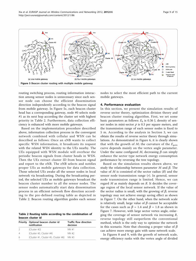
routing switching process, routing information interac-tion among sensor nodes is unnecessary since each sen-sor node can choose the efficient disseminationdirection independently according to the beacon signalfrom mobile gateway. In Figure 5c, each beacon clusterhead has a corresponding gateway, node #0 selects node#1 as its next hop according the cluster set with highestpriority in Table 2. Furthermore, data collection effi-ciency is enhanced with more mobile gateways.Based on the implementation procedure described
above, information collection process in the convergentnetwork combined with cellular and WSN can bedescribed as follows: Once an eNB wants to collectspecific WSN information, it broadcasts its requestwith the related WSN identity to the UEs nearby. TheUEs equipped with WSN module will overhear theperiodic beacon signals from cluster heads in WSN.Then the UEs extract cluster ID from beacon signaland report to the eNB. The eNB selects and notifiesproper UEs as mobile gateways for data collection.Those selected UEs awake all the sensor nodes in localnetwork via broadcasting. During the broadcasting per-iod, the selected UEs as mobile gateways broadcast thebeacon cluster number to all the sensor nodes. Thesensor nodes automatically start data disseminationprocess in an efficient network flow direction accord-ing to the pre-defined routing table as depicted inTable 2. Beacon routing algorithm guides each sensor
nodes to select the most efficient path to the currentmobile gateways.
4. Performance evaluationIn this section, we present the simulation results ofreverse sector theory, optimization division theory andbeacon cluster routing algorithm. First, we set somebasic parameters as follows: Eb is 0.36 J, density of sen-sor nodes in mini-sector r is 0.3 per square meters, andthe transmission range of each sensor nodes is fixed to5 m. According to the analysis in Section 3, we canobtain the results of reverse sector theory through simu-lations. As demonstrated in Figure 6, it is clearly shownthat with the growth of M; the curvature of the Egaincurve depends mainly on the vertex angle parameter.Under the same configured M, decreasing b can simplyenhance the sector type network energy consumptionperformance by reversing the tree topology.Based on the simulation results shown above, we
study the relationship between parameter M and b. Thevalue of M is consisted of the sector radius (R) and thesensor node transmission range (r). In general, sensornode transmission range is limited. Hence, we canregard M as mainly depends on R. It decides the cover-age region of the local sensor network. If the value ofthe sector radius is small, with the growing of b, reversetopology may not achieve energy saving effect as shownin Figure 7. On the other hand, when the network scaleis relatively small, large value of b cannot be acceptablefor the cases such as b = 1.4 and b = 1.8 as shown inFigure 7. However, with large sector vertex angle, enlar-ging the coverage of sensor network via increasing R,reverse topology still outperform the conventionalmethod, which is the only way to optimize the networkin this scenario. Note that choosing a proper value of bcan achieve more energy gain with same network scale.In Figures 8 and 9, with the growth of network scale,
energy efficiency ranks with the vertex angle of divided
Figure 5 Beacon cluster routing with multiple mobile gateway.
Table 2 Routing table according to the combination ofbeacon cluster id
Priority Optional beacon cluster idnotification
Traffic flow directiondecision
2 {Cluster #2} NN #1
4 {Cluster #3, Cluster #4} NN #2
6 {Cluster #1, Cluster #5, Cluster #6} NN #3
Xia et al. EURASIP Journal on Wireless Communications and Networking 2012, 2012:86http://jwcn.eurasipjournals.com/content/2012/1/86
Page 9 of 15

Figure 6 Energy saved under large-scale network.
Figure 7 Energy saved under small-scale network.
Xia et al. EURASIP Journal on Wireless Communications and Networking 2012, 2012:86http://jwcn.eurasipjournals.com/content/2012/1/86
Page 10 of 15
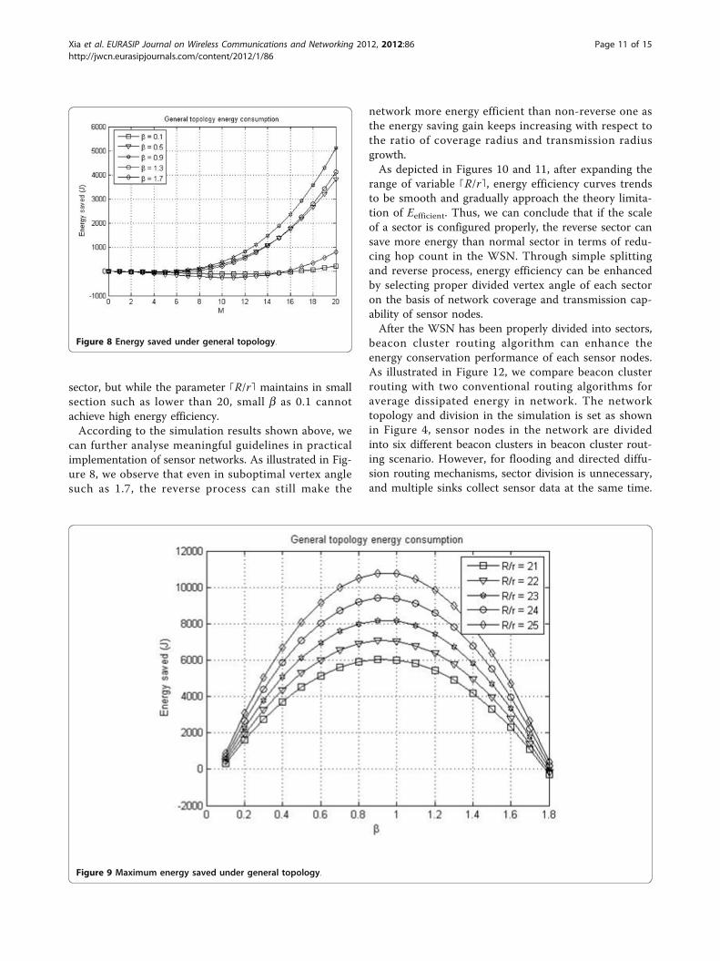
sector, but while the parameter ⌈R/r⌉ maintains in smallsection such as lower than 20, small b as 0.1 cannotachieve high energy efficiency.According to the simulation results shown above, we
can further analyse meaningful guidelines in practicalimplementation of sensor networks. As illustrated in Fig-ure 8, we observe that even in suboptimal vertex anglesuch as 1.7, the reverse process can still make the
network more energy efficient than non-reverse one asthe energy saving gain keeps increasing with respect tothe ratio of coverage radius and transmission radiusgrowth.As depicted in Figures 10 and 11, after expanding the
range of variable ⌈R/r⌉, energy efficiency curves trendsto be smooth and gradually approach the theory limita-tion of Eefficient. Thus, we can conclude that if the scaleof a sector is configured properly, the reverse sector cansave more energy than normal sector in terms of redu-cing hop count in the WSN. Through simple splittingand reverse process, energy efficiency can be enhancedby selecting proper divided vertex angle of each sectoron the basis of network coverage and transmission cap-ability of sensor nodes.After the WSN has been properly divided into sectors,
beacon cluster routing algorithm can enhance theenergy conservation performance of each sensor nodes.As illustrated in Figure 12, we compare beacon clusterrouting with two conventional routing algorithms foraverage dissipated energy in network. The networktopology and division in the simulation is set as shownin Figure 4, sensor nodes in the network are dividedinto six different beacon clusters in beacon cluster rout-ing scenario. However, for flooding and directed diffu-sion routing mechanisms, sector division is unnecessary,and multiple sinks collect sensor data at the same time.
Figure 8 Energy saved under general topology.
Figure 9 Maximum energy saved under general topology.
Xia et al. EURASIP Journal on Wireless Communications and Networking 2012, 2012:86http://jwcn.eurasipjournals.com/content/2012/1/86
Page 11 of 15

Figure 10 Energy efficiency under small-scale network.
Figure 11 Energy efficiency under large-scale network.
Xia et al. EURASIP Journal on Wireless Communications and Networking 2012, 2012:86http://jwcn.eurasipjournals.com/content/2012/1/86
Page 12 of 15

Note that flooding is set as the benchmark for the per-formance comparison, and even diffusion performsmuch better than flooding. Beacon cluster routing out-performs the diffusion by more than 50% in terms ofenergy dissipation. Noticeably, beacon cluster routingdissipates less energy than these two conventionalmechanisms since additional routing data exchangingprocedures are replaced by local computation.Figure 13 shows the delay performance comparison of
three routing algorithms. As mentioned above, beaconcluster routing algorithm transfers the routing consump-tion into local computation consumption, each sensornodes can deliver the packets immediately when thebeacon broadcasting arrives. Thus, these three routingalgorithms are separated with different order of magni-tude in the delay performance comparison. With theincrease of network scale, beacon cluster routing algo-rithm shows lower growth rate of network delay whilethe flooding obviously deteriorates network transmissionefficiency. Furthermore, it is clearly shown that the bea-con cluster routing is more efficient than the diffusionapproach.
5. ConclusionsIn this article, we proposed a beacon cluster based rout-ing algorithm for the convergence of WSN and cellularnetwork service applications. By virtue of the proposedsolutions, it is possible to improve the energy and
information collection efficiency in WSN. With the opti-mal network pre-implementation according to the sectorsplitting scheme, sub-optimization can be achieved ineach divided beacon clusters. Accordingly, the perfor-mance of the whole network is optimized via optimaldivision during the routing procedure. More than 50%of the energy consumption can be saved comparingwith conventional network. Furthermore, it is possibleto reduce the re-clustering communication overheadsince the change of routes between the sensor nodes isminimized. Sensor network topology can adapt to thedata collection pattern of real-time quantity and positionof mobile gateways flexibly. Meanwhile the re-routingexpenditure has been transformed to lower the distribu-ted calculation consumption in the sensor network.Analysis in this article is considered in the worst situa-
tions such as full binary tree while in practical scenarios,network structure can be simpler. This indicates that wehave given the lower bound of the performance evalua-tion. With the optimization scheme we proposed inpractical implementation, network performance can out-perform our estimation in this paper. Trade-off betweennetwork scale and divided angle is helpful for networkimplementation. While we enlarge the scale of local sen-sor network via installing new sensor nodes for newrequirement, divided angle of certain sectors should bere-configured in order to maintain the network work inoptimal energy efficient status. Similarly, we may
Figure 12 Average dissipated energy.
Xia et al. EURASIP Journal on Wireless Communications and Networking 2012, 2012:86http://jwcn.eurasipjournals.com/content/2012/1/86
Page 13 of 15

reconfigure the density of the sensor nodes which inturn will decrease the transmission rage of single nodeto reach the goal of energy saving. Finally, we have pre-sented simulation results to show the performance ofthe proposed algorithm. In addition, our proposed algo-rithms can be considered to further optimize in largescale wireless networks [20].
Author details1Shanghai Institute of Micro-system and Information Technology (SIMIT),Chinese Academy of Sciences (CAS), Shanghai, China 2The State KeyLaboratory of Integrated Services Networks (ISN), China 3Renesas Tele. Tech.(Beijing) Ltd., Shanghai, China 4Shanghai Advanced Research Institute,Chinese Academic of Science, Shanghai, China
Competing interestsPartial content is patented by Renesas Tele. Tech. (Beijing) Ltd., Shanghai,China.This work is supported by the National Science and Technology MajorProject of the Ministry of Science and Technology of China under Grant No.2009ZX03005-002-01, and National High-tech R&D Program (863 Program) ofChina under Grant No. 2009AA012002.This work is partially supported by the open research fund of the State KeyLaboratory of Integrated Services Networks, Xidian University, China, andNatural Science Foundation of Shanghai under Grant 10ZR1436000, NationalHigh-Tech R&D Program (863 Program) of China under GrantNo.2011AA01A105.
Received: 15 July 2011 Accepted: 6 March 2012Published: 6 March 2012
References1. D Estrin, R Govindan, J Heidemann, S Kumar, Next century challenges:
scalable coordination in sensor networks, in 5th Annual InternationalConference on Mobile Computing and Networking (MobiCom 1999), Seattle,WA, 1999, pp. 263–270
2. J Heidemann, F Silva, C Intanagonwiwat, R Govindan, D Estrin, D Ganesan,Building efficient wireless sensor networks with low-level naming. inSymposium on Operating Systems Principles. New York, 2001 35(5), 146–159
3. G Pottie, W Kaiser, Wireless integrated network sensors. Commun ACM.43(5), 51–58 (2000). doi:10.1145/332833.332838
4. S Hedetniemi, A Liestman, A survey of gossiping and brocadcasting incommunication networks. IEEE Network. 18(4), 319–349 (1988)
5. J Gao, L Guibas, J Hershberger, L Zhang, A Zhu, Geometric spanners forrouting in mobile networks, in 2nd ACM International Symposium on MobileAd Hoc Networking and Computing (MobiHoc 2001), New York, 2001, pp.45–55
6. L Zhao, G Liu, J Chen, ZW Zhang, Flooding and directed diffusion routingalgorithm in wireless sensor networks, in Ninth International Conference onHybrid Intelligent Systems, Shenyang, 2009, pp. 235–239
7. WR Heinzelman, J Kulik, H Balakrishnan, Adaptive protocols for informationdissemination in wireless sensor networks, in Proceedings of the ACMMobiCom’99, Seattle, WA, 1999, pp. 174–185
8. C Intanagonwiwat, R Govindan, D Estrin, Directd diffusion: a scalable androbust communication paradigm for sensor networks, MobiCom ‘00Proceedings of the 6th annual international conference on Mobilecomputing and networking, New York, 2000, pp. 56–67
9. K Hwang, D Eom, Adaptive sink mobility management scheme for wirelesssensor networks. Lecture Notes in Computer Science (LNCS). 4159 (2006)
10. G Wang, T Wang, W Jia, M Guo, HH Chen, M Guizani, Local update-basedrouting protocol in wireless sensor networks with mobile sinks, ICC ‘07. IEEEInternational Conference, Glasgow 3094–3099 (2007)
11. J Li, L Huang, G Wang, A novel clustering algorithm by using mobilegateways in densely deployed sensor networks. in ICIA 2008. InternationalConference on Information and Automation 1553–1559 (2008)
Figure 13 Delay performance comparison.
Xia et al. EURASIP Journal on Wireless Communications and Networking 2012, 2012:86http://jwcn.eurasipjournals.com/content/2012/1/86
Page 14 of 15

12. K Langendoen, Medium Access Control in Wireless Networks, chapt. Energy-Efficient Medium Access Control, (Nova Science Publishers, 2008), pp.535–560
13. M Dohler, D Barthel, F Maraninchi, L Mounier, S Aubert, C Dugas, A Buhrig,F Paugnat, M Renaudin, A Duda, M Heusse, F Valois, The ARESA project:facilitating research, development and commercialization of WSNs, in 4thAnnual IEEE Communications Society Conference on Sensor, Mesh and Ad HocCommunications and Networks (SECON), San Diego, CA, USA, pp. 590–599(June 2007)
14. C Dugas, Configuring and managing a large-scale monitoring networksolving real world challenges for ultra-low powered and longrange wirelessmesh networks. Int J Netw Manag. 15, 269–282 (2005). doi:10.1002/nem.573
15. A Bachir, M Dohler, T Watteyne, K Leung, Mac essentials for wireless sensornetworks. IEEE Commun Surv Tutor. 12(2), 222–248 (2010)
16. P Gupta, PR Kumar, The capacity of wireless networks. IEEE Trans Inf Theory.46(2), 388–404 (2000). doi:10.1109/18.825799
17. A El-Hoiydi, Aloha with preamble sampling for sporadic traffic in ad hocwireless sensor networks, in ICC, vol. 5. New York, NY, IEEE, 2002, pp.3418–3423
18. J Hill, D Culler, Mica: a wireless platform for deeply embedded networks.IEEE Micro. 22(6), 12–24 (2002). doi:10.1109/MM.2002.1134340
19. W Ye, F Silva, J Heidemann, Ultra-low duty cycle MAC with scheduledchannel polling, in 4th ACM Conference on Embedded Networked SensorSystems (SenSys), Boulder, CO, ACM, pp. 321–334 (November 1–3 2006)
20. X Wang, W Huang, S Wang, J Zhang, C Hu, Delay and capacity tradeoffanalysis for motioncast. IEEE/ACM Trans Netw. 19(5), 1354–1367 (2011)
doi:10.1186/1687-1499-2012-86Cite this article as: Xia et al.: Beacon routing algorithm in wirelesssensor networks with mobile gateway. EURASIP Journal on WirelessCommunications and Networking 2012 2012:86.
Submit your manuscript to a journal and benefi t from:
7 Convenient online submission
7 Rigorous peer review
7 Immediate publication on acceptance
7 Open access: articles freely available online
7 High visibility within the fi eld
7 Retaining the copyright to your article
Submit your next manuscript at 7 springeropen.com
Xia et al. EURASIP Journal on Wireless Communications and Networking 2012, 2012:86http://jwcn.eurasipjournals.com/content/2012/1/86
Page 15 of 15