Embed Size (px)
Citation preview

Integration™
Using EDI with
V e r s i o n 2 . 1D o c u m e n t D a t e : O c t o b e r 2 0 0 1
WebLogic Integration
BEA WebLogic
R e v i s e d : N o v e m b e r 2 , 2 0 0 1

Copyright
Copyright © 2001 BEA Systems, Inc. All Rights Reserved.
Restricted Rights Legend
This software and documentation is subject to and made available only pursuant to the terms of the BEA SystemsLicense Agreement and may be used or copied only in accordance with the terms of that agreement. It is againstthe law to copy the software except as specifically allowed in the agreement. This document may not, in whole orin part, be copied photocopied, reproduced, translated, or reduced to any electronic medium or machine readableform without prior consent, in writing, from BEA Systems, Inc.
Use, duplication or disclosure by the U.S. Government is subject to restrictions set forth in the BEA SystemsLicense Agreement and in subparagraph (c)(1) of the Commercial Computer Software-Restricted Rights Clauseat FAR 52.227-19; subparagraph (c)(1)(ii) of the Rights in Technical Data and Computer Software clause atDFARS 252.227-7013, subparagraph (d) of the Commercial Computer Software--Licensing clause at NASA FARsupplement 16-52.227-86; or their equivalent.
Information in this document is subject to change without notice and does not represent a commitment on the partof BEA Systems. THE SOFTWARE AND DOCUMENTATION ARE PROVIDED “AS IS” WITHOUTWARRANTY OF ANY KIND INCLUDING WITHOUT LIMITATION, ANY WARRANTY OFMERCHANTABILITY OR FITNESS FOR A PARTICULAR PURPOSE. FURTHER, BEA Systems DOESNOT WARRANT, GUARANTEE, OR MAKE ANY REPRESENTATIONS REGARDING THE USE, OR THERESULTS OF THE USE, OF THE SOFTWARE OR WRITTEN MATERIAL IN TERMS OF CORRECTNESS,ACCURACY, RELIABILITY, OR OTHERWISE.
Trademarks or Service Marks
BEA, Jolt, Tuxedo, and WebLogic are registered trademarks of BEA Systems, Inc. BEA Builder, BEA CampaignManager for WebLogic, BEA eLink, BEA Manager, BEA WebLogic Commerce Server, BEA WebLogicE-Business Platform, BEA WebLogic Enterprise, BEA WebLogic Express, BEA WebLogic Integration, BEAWebLogic Personalization Server, BEA WebLogic Portal, BEA WebLogic Server and How Business BecomesE-Business are trademarks of BEA Systems, Inc.
All other trademarks are the property of their respective companies.
Using EDI with WebLogic Integration
Part Number Date Software Version
N/A October 2001
Revised: November 2, 2001
2.1

Using EDI with WebLogic Integration iii
Contents
1. EDI BackgroundWhat Is EDI? ..................................................................................................... 1-1
Architecture Overview ............................................................................... 1-2
Message Structure ...................................................................................... 1-2
Differences with Other E-Commerce Standards........................................ 1-5
EDI Standards.................................................................................................... 1-6
X12 ............................................................................................................. 1-6
EDIFACT ................................................................................................... 1-7
TRADACOMS........................................................................................... 1-7
BEA WebLogic EDI Integration Architecture .................................................. 1-7
BEA WebLogic Adapter for Power.Enterprise! ........................................ 1-8
Power.Enterprise! Software ....................................................................... 1-8
2. ArchitectureEDI Integration Architecture ............................................................................. 2-1
Power.Enterprise! Architecture ......................................................................... 2-2
Feature Overview ....................................................................................... 2-2
Supported Standards ........................................................................... 2-3
Limitations .......................................................................................... 2-3
Power.Map! ................................................................................................ 2-4
Creating and Maintaining Maps.......................................................... 2-4
Creating and Maintaining Documents ................................................ 2-5
Power.Manager! ......................................................................................... 2-5
Trading Partner Maintenance.............................................................. 2-5
Connections......................................................................................... 2-5
Exchange Profiles ............................................................................... 2-6
Document Tracking............................................................................. 2-6

iv Using EDI with WebLogic Integration
Administration..................................................................................... 2-6
VAN and Network Connectivity ....................................................................... 2-6
3. BEA WebLogic Adapter for Power.Enterprise! 3.0Overview of Application Integration................................................................. 3-1
Application Views...................................................................................... 3-2
Configuring the BEA WebLogic Adapter for Power.Enterprise! .............. 3-3
Events ......................................................................................................... 3-6
Configuring Events ............................................................................. 3-7
Testing an Event.................................................................................. 3-9
Services....................................................................................................... 3-9
Configuring Services......................................................................... 3-10
Testing a Service ............................................................................... 3-11
Using the Adapter Plug-In to the BEA WebLogic Integration Studio ............ 3-11
Deploying an Adapter in a New WebLogic Integration Domain............. 3-12
Exception Handling ......................................................................................... 3-13
4. Configuring Power.Enterprise!Installing Power.Enterprise! .............................................................................. 4-1
Getting Licenses ......................................................................................... 4-3
Installing the Power.Server! ....................................................................... 4-3
Installing the Power.Client!........................................................................ 4-3
Connecting to Get2Connect.Net................................................................. 4-4
Installing Cleo A+ ...................................................................................... 4-4
Downloading Software Updates................................................................. 4-4
Updating EDI Document Descriptions....................................................... 4-4
Connecting to a Server for the First Time .................................................. 4-5
Configuring Power.Enterprise!.......................................................................... 4-7
Configuring Trading Partners ............................................................................ 4-8
Mapping XML and EDI Data .......................................................................... 4-10
Connections and VAN Connectivity ............................................................... 4-12
Creating RMI Connections................................................................ 4-13
Creating Trading Partner Connections.............................................. 4-15
Configuring Exchange Profiles ....................................................................... 4-16

Using EDI with WebLogic Integration v
5. Configuring EDI IntegrationGeneral Configuration ....................................................................................... 5-1
Configure Trading Partners ........................................................................ 5-2
Configure VAN/Trading Partner Connectivity .......................................... 5-2
Configuring EDI Integration to Receive an EDI Document ............................. 5-2
Pre-Planning........................................................................................ 5-3
Within Power.Enterprise!.................................................................... 5-3
Within BEA WebLogic Integration .................................................... 5-4
Configuring EDI Integration to Send an EDI Document .................................. 5-5
Pre-Planning........................................................................................ 5-5
Within Power.Enterprise!.................................................................... 5-5
Within BEA WebLogic Integration .................................................... 5-6
6. EDI SampleSample Overview .............................................................................................. 6-1
Setting up and Running the Sample .................................................................. 6-3
Prerequisites ............................................................................................... 6-3
Hardware and OS Requirements ................................................................ 6-3
Configuring the EDI Sample...................................................................... 6-3
Step 1: Start Power.Server! ................................................................. 6-4
Step 2: Start Power.Manager! and Configure Partners ....................... 6-4
Step 3: Start Power.Map! and Load Maps and Adapters ................... 6-9
Step 4: Set Up the Connections......................................................... 6-14
Step 5: Set Up the Exchange Profiles ............................................... 6-19
Step 6: Set Up the Workflow ............................................................ 6-22
Step 7: Deploy the Application View ............................................... 6-23
Step 8: Run the Sample..................................................................... 6-24
7. Power.Enterprise! Tuning GuideTuning the Java Virtual Machine ...................................................................... 7-1
Tuning the Database .......................................................................................... 7-4
Tuning Power.Server!........................................................................................ 7-6
HTTP and HTTPS Server Configuration .......................................................... 7-7

vi Using EDI with WebLogic Integration
Using EDI with WebLogic Integration vii
About This Document
This document describes Electronic Data Interchange (EDI) and explains how to usethe BEA WebLogic Adapter for Power.Enterprise! 3.0 to interconnect with yourtrading partners using EDI in the BEA WebLogic environment.
This document includes the following topics:
� Chapter 1, “EDI Background,” provides background information about EDIsystems and standards.
� Chapter 2, “Architecture,” describes the structure of EDI Integration and itscomponent parts.
� Chapter 3, “BEA WebLogic Adapter for Power.Enterprise! 3.0,” explains how toinstall and configure this product.
� Chapter 4, “Configuring Power.Enterprise!.” explains how you need to configurePower.Enterprise! to interoperate with BEA WebLogic Integration and the BEAWebLogic Adapter for Power.Enterprise! 3.0.
� Chapter 5, “Configuring EDI Integration,” explains the end-to-end configurationrequirements of EDI Integration.
� Chapter 6, “EDI Sample,” walks you through the configuration and use of anexample scenario in which EDI is used to support a simple purchase orderbusiness process.
� Chapter 7, “Power.Enterprise! Tuning Guide.” explains how to tune thePower.Enterprise! software for improved performance in your deploymentenvironment.

viii Using EDI with WebLogic Integration
What You Need to Know
This guide is written for business analysts and system administrators developing andimplementing EDI integration. We assume that you have a basic understanding of EDIand networking concepts, and that you are familiar with the WebLogic Integrationenvironment
e-docs Web Site
BEA product documentation is available on the BEA corporate Web site. From theBEA Home page, click on Product Documentation or go directly to the “e-docs”Product Documentation page at http://e-docs.bea.com.
How to Print the Document
You can print a copy of this document from a Web browser, one file at a time, by usingthe File→Print option on your Web browser.
A PDF version of this document is available on the WebLogic Integrationdocumentation Home page on the e-docs Web site (and also on the documentationCD). You can open the PDF in Adobe Acrobat Reader and print the entire document(or a portion of it) in book format. To access the PDFs, open the WebLogic Integrationdocumentation Home page, click the PDF files button and select the document youwant to print.
If you do not have the Adobe Acrobat Reader, you can get it for free from the AdobeWeb site at http://www.adobe.com/.
Using EDI with WebLogic Integration ix
Related Information
For general information about EDI and EDI standards, see the following Web sites:
� Accredited Standards Committee X12 Web site at http://www.x12.org/
� UN EDIFACT Web site athttp://www.unece.org/trade/untdid/welcome.htm
Contact Us!
Your feedback on the BEA WebLogic Integration documentation is important to us.Send us e-mail at [email protected] if you have questions or comments. Yourcomments will be reviewed directly by the BEA professionals who create and updatethe WebLogic Integration documentation.
In your e-mail message, please indicate that you are using the documentation for theBEA WebLogic Integration 2.1 release.
If you have any questions about this version of BEA WebLogic Integration, or if youhave problems installing and running BEA WebLogic Integration, contact BEACustomer Support through BEA WebSupport at www.bea.com. You can also contactCustomer Support by using the contact information provided on the Customer SupportCard, which is included in the product package.
When contacting Customer Support, be prepared to provide the following information:
� Your name, e-mail address, phone number, and fax number
� Your company name and company address
� Your machine type and authorization codes
� The name and version of the product you are using
� A description of the problem and the content of pertinent error messages

x Using EDI with WebLogic Integration
Documentation Conventions
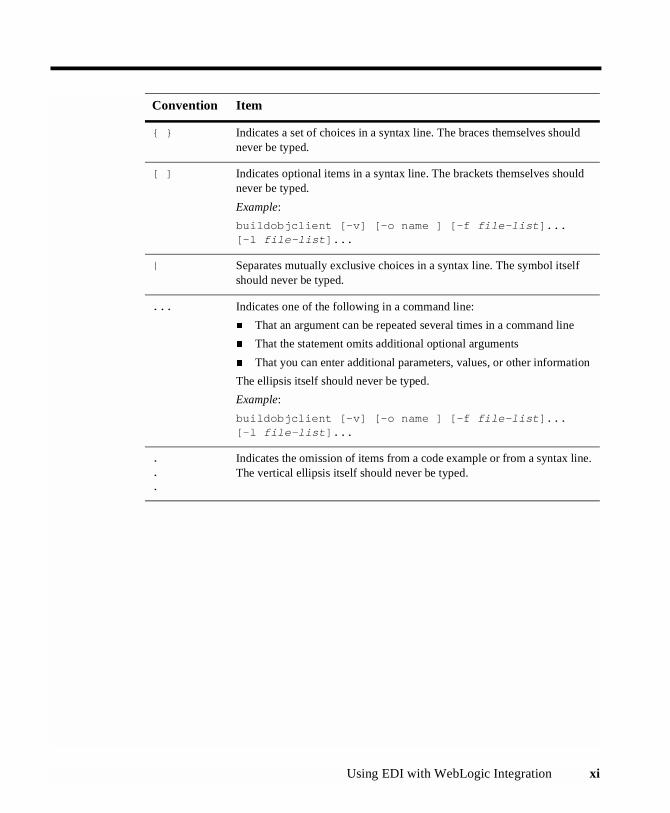
The following documentation conventions are used throughout this document.
Convention Item
boldface text Indicates terms defined in the glossary.
Ctrl+Tab Indicates that you must press two or more keys simultaneously.
italics Indicates emphasis or book titles.
monospacetext
Indicates code samples, commands and their options, data structures andtheir members, data types, directories, and file names and their extensions.Monospace text also indicates text that you must enter from the keyboard.
Examples:
#include <iostream.h> void main ( ) the pointer psz
chmod u+w *
\tux\data\ap
.doc
tux.doc
BITMAP
float
monospaceboldfacetext
Identifies significant words in code.
Example:
void commit ( )
monospaceitalictext
Identifies variables in code.
Example:
String expr
UPPERCASETEXT
Indicates device names, environment variables, and logical operators.
Examples:
LPT1
SIGNON
OR
Using EDI with WebLogic Integration xi
{ } Indicates a set of choices in a syntax line. The braces themselves shouldnever be typed.
[ ] Indicates optional items in a syntax line. The brackets themselves shouldnever be typed.
Example:
buildobjclient [-v] [-o name ] [-f file-list]...[-l file-list]...
| Separates mutually exclusive choices in a syntax line. The symbol itselfshould never be typed.
... Indicates one of the following in a command line:
� That an argument can be repeated several times in a command line
� That the statement omits additional optional arguments
� That you can enter additional parameters, values, or other information
The ellipsis itself should never be typed.
Example:
buildobjclient [-v] [-o name ] [-f file-list]...[-l file-list]...
.
.
.
Indicates the omission of items from a code example or from a syntax line.The vertical ellipsis itself should never be typed.
Convention Item

xii Using EDI with WebLogic Integration
Using EDI with WebLogic Integration 1-1
CHAPTER
1 EDI Background
This section presents an overview of Electronic Data Interchange (EDI), the variousEDI standards, and BEA’s EDI Integration. It includes the following topics:
� What Is EDI?
� EDI Standards
� BEA WebLogic EDI Integration Architecture
What Is EDI?
Electronic Data Interchange (EDI) is a set of common data format standards developedin the U.S. and Western Europe in the late 1970s.The goal of the American NationalStandards Institute (ANSI), which sponsored the initial creation of what became theX12 set of EDI standards, was to establish a group of nationally recognized dataformats that:
� Were hardware independent
� Were unambiguous, such that they could be used by all trading partners
� Reduced the amount of labor-intensive work required to exchange data (forexample, by eliminating the need for data re-entry
� Allowed the sender of the data to control the exchange, and to know whetherand when the recipient received the transaction

1 EDI Background
1-2 Using EDI with WebLogic Integration
After sponsoring the initial definition of the standards, ANSI created the AccreditedStandards Committee (ASC) to maintain and develop the X12 standard. The resultingX12 standards define the data formats and encoding rules used for a wide variety ofbusiness transactions, including order placement and processing, shipping andreceiving, invoicing, payment, and many more.
To create a single international EDI standard, the United Nations/ EconomicCommission for Europe (UN/ECE) Working Party on Facilitation of InternationalTrade Procedures created the UN/EDIFACT family of standards. The EDIFACTsyntax was adopted by the International Standards Organization (ISO) in 1987.
The X12 and EDIFACT standards provide equivalent functionality. The X12standards are older and more mature; they provide functionality not yet available inEDIFACT. Much of this unavailable functionality is, however, under development forthe EDIFACT standards.
The differences between X12 and EDIFACT arise primarily from their underlying datastructures. (For example, data elements and data segments.) There is no one-to-onecorrespondence between X12 and EDIFACT data elements; multiple X12 dataelements may be needed to represent a single EDIFACT data element.
Architecture Overview
The X12 and EDIFACT standards are hierarchical sets of message element structures.At the bottom of each hierarchy, simple data structures are combined to form morecomplex data structures. The top of each message structure hierarchy is populated byinformation units exchanged by trading partners.
Different hierarchies and data structures are defined for different data sets. Forexample, an X12 997 message (a Functional Acknowledgment) is quite different froman X12 810 message (an Invoice), and the requirements for both are different fromthose for an X12 130 message (a Student Educational Record, or transcript).
Message Structure
At the base of each EDI standard is a dictionary of simple data elements. A simple dataelement represents the smallest named item in an X12 or EDIFACT standard, such asa qualifier, a value, or a description. Examples of simple data elements include:
What Is EDI?
Using EDI with WebLogic Integration 1-3
� Invoice date
� Weight capacity
� Exchange rate
� Hazardous material classification
� Unit of measurement code (such as pounds, dozens, cubic feet, gallons, and soon)
The X12 standard also defines a composite data element. A composite data element isa set of simple data elements that represents a single named item. For example, in anX12 130 message, the composite data element C002 is used to identify the actions tobe performed on a piece of paperwork, and comprises five simple data elements. Eachsimple data element is a code identifying one required action.
Data elements are grouped into functionally related units called data segments. Anexample of a data segment is the address of a geographic location, which includes thedata elements for a city name, a state or province code, a postal code, and a countrycode. Data segments are defined in the X12 segment directory, which lists the dataelements, in the required order, that make up each data segment.
Data segments are grouped, in turn, into transaction sets. A transaction set is thesmallest meaningful set of information exchanged by trading partners. It represents acommon business document, such as a purchase order or invoice. Most transaction setsare divided into three areas (called tables), each of which corresponds to a part of aprinted document:
� Table 1, the Transaction Set Header, is the heading area, in which informationpertinent to the entire transaction is placed.
� Table 2, the detail area, is composed of one or more data segments. Forexample, the line items for a purchase order are placed in the detail area.
� Table 3, the Transaction Set Trailer, is the summary area, which containsinformation such as the number of data segments used in a transaction set.

1 EDI Background
1-4 Using EDI with WebLogic Integration
Figure 1-1 Structure of a Transaction Set
Although a transaction set represents a printed document, it is not the information unitexchanged in an EDI transaction. Similar transaction sets are arranged into functionalgroups. For example, if Company A sends Company B two Requests for Quotations(RFQs) and five Purchase Orders (POs), the two RFQs are combined into onefunctional group, and the five POs are combined into another. All functional groupsdestined for a particular trading partner are then combined into an information unitcalled an EDI interchange. It is these interchanges that are transmitted between tradingpartners.
With the advent of readily-available high-speed networking, many EDI systems havemoved to real-time EDI interchange, in which each transaction set is transmitted to atrading partner, if possible, as it arrives at the EDI system as a separate EDIinterchange. In older systems, transaction sets are batched together and transmitted asone or more composite EDI interchanges. Because of the breadth and depth of EDIpenetration into the e-commerce marketplace, you may encounter both situations withyour trading partners.
The functional groups of an interchange are wrapped within an interchange header andtrailer. The header provides control information:
� Sender and receiver of the interchange
� Date and time of the interchange

What Is EDI?
Using EDI with WebLogic Integration 1-5
� Standard and version of the interchange
� Authorization and security information
� Unique control number by which the interchange can be tracked.
The trailer ends the interchange. It provides the total number of functional groups inthe interchange, and it repeats the unique interchange control number identified in theheader.
The following illustration shows how all of this is put together to form an X12 EDImessage. EDIFACT and TRADACOMS messages use similar, though not identical,message structures.
Figure 1-2 X12 Message Structure
Differences with Other E-Commerce Standards
E-commerce standards other than EDI, such as RosettaNet, BizTalk, and CXML aredesigned to take advantage of state-of-the-are technology, but they are not completelyfree of restrictions. Generally, these e-commerce standards require the following:
� Use of HTTP and/or HTTPS as the standard transport protocol
� Use of XML to package data
� Assume real-time access to trading partners

1 EDI Background
1-6 Using EDI with WebLogic Integration
� Structure that supports delivery of one transaction per datagram
In addition, because these standards are relatively new, they are generally restricted toa small industry segment, with a relatively limited number of transaction messagesavailable. At the same time, other e-commerce standards evolve relatively quickly,adding new functionality very quickly.
In contrast, EDI offers a wide variety of already-established standards, including thethree most common - X12, EDIFACT, and TRADACOMS. These standards providea wide variety of transaction types, addressing a broad variety of industry andgovernment segments.
EDI Standards
Currently, there are three primary EDI standards: X12, EDIFACT, andTRADACOMS.
X12
The X12 standard is maintained by the ANSI Accredited Standards Committee(http://www.x12.org/). It is used primarily within the U.S. and North America.The U.S. Federal government has chartered the National Institute of Standards andTechnology to maintain a Federal registry of all EDI implementation standards as theyare used by the Federal government. For details, go to(http://snad.ncsl.nist.gov/dartg/edi/fededi.html).
New releases of the X12 standard, incorporating technical updates and new EDItransactions, are published regularly.

BEA WebLogic EDI Integration Architecture
Using EDI with WebLogic Integration 1-7
EDIFACT
The EDIFACT standard is maintained by the United Nations/Economic Commissionfor Europe (UN/ECE) and the International Standards Organization(http://www.unece.org/trade/untdid/). The EDIFACT standard is usedprimarily within Europe.
TRADACOMS
The TRADACOMS standard was developed and is maintained by the ANA (ArticleNumbering Association) (http://195.40.68.190/ana/helppubl.htm). It is usedprimarily in the U.K. retail industry.
BEA WebLogic EDI Integration Architecture
BEA provides comprehensive EDI support through the BEA WebLogic Adapter forPower.Enterprise! 3.0 and Power.Enterprise! software. Figure 1-3 illustrates how theBEA WebLogic Adapter for Power.Enterprise! and Power.Enterprise! software worktogether put WebLogic Integration to work with your trading partners’ EDI systems.
Figure 1-3 BEA EDI Integration Architecture

1 EDI Background
1-8 Using EDI with WebLogic Integration
BEA WebLogic Adapter for Power.Enterprise!
The BEA WebLogic Adapter for Power.Enterprise! provides a gateway betweenWebLogic Integration and the Power.Enterprise! software. Using standard applicationintegration events and services that you define using BEA WebLogic technology, BEAWebLogic Adapter for Power.Enterprise! allows you to:
� Exchange XML documents with your trading partner, via Power.Enterprise!
� Receive documents from a trading partner via Power.Enterprise!
Power.Enterprise! Software
Power.Enterprise! is a suite of three components: Power.Server!, Power.Map!, andPower.Manager!. These components enable you to define your EDI to XML documentmaps, manage your trading partner relationships, and handle the transmission andreceipt of EDI messages.

Using EDI with WebLogic Integration 2-1
CHAPTER
2 Architecture
The following sections describe the architecture of EDI Integration, includinginformation about the BEA WebLogic Adapter for Power.Enterprise!, thePower.Enterprise! software, and VAN/network connectivity:
� EDI Integration Architecture
� Power.Enterprise! Architecture
� VAN and Network Connectivity
EDI Integration Architecture
BEA provides comprehensive EDI support using the BEA WebLogic Adapter forPower.Enterprise! and the Power.Enterprise! software suite. Figure 2-1 shows how theBEA WebLogic Adapter for Power.Enterprise! and Power.Enterprise! combine to putWebLogic Integration to work with your trading partners’ EDI systems.
Figure 2-1 BEA EDI Integration Architecture
The EDI Adapter uses application integration to allow WebLogic Integration toexchange XML documents with Power.Enterprise!, using RMI message passing.
2 Architecture
2-2 Using EDI with WebLogic Integration
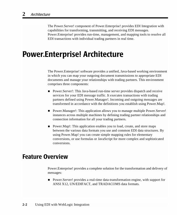
The Power.Server! component of Power.Enterprise! provides EDI Integration withcapabilities for transforming, transmitting, and receiving EDI messages.Power.Enterprise! provides run-time, management, and mapping tools to resolve allEDI transactions with individual trading partners in real time.
Power.Enterprise! Architecture
The Power.Enterprise! software provides a unified, Java-based working environmentin which you can map your outgoing document transmissions to appropriate EDIdocuments and manage your relationships with trading partners. This environmentcomprises three components:
� Power.Server!: This Java-based run-time server provides dispatch and receiveservices for your EDI message traffic. It executes transactions with tradingpartners defined using Power.Manager!. Incoming and outgoing messages aretransformed in accordance with the definitions you establish using Power.Map!.
� Power.Manager!: This application allows you to manage multiple Power.Server!instances across multiple machines by defining trading partner relationships andconnection information for all your trading partners.
� Power.Map!: This application enables you to load, create, and store mapsbetween the various data formats you use and common EDI data structures. Byusing Power.Map! you can create simple mapping rules for elementaryconversions, or use formulas or JavaScript for more complex and sophisticatedconversions.
Feature Overview
Power.Enterprise! provides a complete solution for the transformation and delivery ofmessages:
� Power.Server! provides a real-time data-transformation engine, with support forANSI X12, UN/EDIFACT, and TRADACOMS data formats.

Power.Enterprise! Architecture
Using EDI with WebLogic Integration 2-3
� Power.Map! is an extensible mapping tool that provides drag-and-dropfunctionality for your mapping. It also allows you to use formulas or JavaScriptcode for more complex conversions.
� Power.Manager! is the configuration and management tool, which allows you toconfigure trading partner relationships and single-direction connections.
Power.Enterprise! is also equipped with IP-level connectivity to the Get2ConnectVAN, and it supports a variety of standard network connection protocols.
Supported Standards
Power.Enterprise! supports the following EDI and data standards:
� X12
� EDIFACT
� TRADACOMS
� XML
� Flat file
Limitations
Currently the Power!Enterprise suite is available on the following systems:
� Power.Server! is available for Windows NT/2000, Solaris, HPUX, and AIXsystems.
� Power.Enterprise! requires an SQL database to function. It supports Oracle 8i(8.1.7 or later), Microsoft SQLServer 7.0 or 2000, and IBM DB2 databases.
� Power.Map! and Power.Manager! are available only for Windows NT/2000systems.

2 Architecture
2-4 Using EDI with WebLogic Integration
Power.Map!
Power.Map! is a tool that defines the data format-mapping capabilities available inPower.Enterprise!. It supports conversion of data into and out of EDI formats, allowingyou to choose any document structure standard supported by Power.Map!, whilemaintaining your ability to interoperate with a variety of standard and tradingpartner-specific EDI formats.
Power.Map! requires three items:
� Data definition for the source document
� Data definition for the target document
� Map of links between data in the source document and data in the targetdocument
You must provide separate data definitions, such as DTDs or XSDs, for any dataformat not already defined in Power.Map!. With Power.Map! you can build XML datastructures within the application, or you can import DTDs and schemas that areexternally created. Once those documents are imported into Power.Map!, you candefine a map for them.
Although Power.Map! supports the import of XML DTDs and schemas for datadefinitions, it does not provide a data format export capability; document formats mayonly be imported. For this reason, you should design your data interchange documentsoutside Power.Map!, then import a copy to Power.Map! to create a map.
Power.Map! includes built-in definitions for most standard EDI messages, includingsupport for X12, EDIFACT, and TRADACOMS messages.
Creating and Maintaining Maps
Power.Map! allows you to create, maintain, and test maps off-line, that is, without anyconnections to a server. These maps are based on document definitions that you mayimport, EDI document definitions supplied with Power.Map!, and custom definitionsthat you may define. Power.Map! allows you to export a map that you have defined,or import a map created elsewhere.

Power.Enterprise! Architecture
Using EDI with WebLogic Integration 2-5
Creating and Maintaining Documents
Document definitions that you intend to use with Power.Server! should be maintainedseparately. Power.Map! supports only the import of XML DTDs and XSDs. Thesedocuments cannot be used outside Power.Map! (for example, they cannot be used inWebLogic Integration) unless they are created outside Power.Map!.
In addition, you should verify the EDI document standards that you will be using.While a variety of standards and versions are supported within Power.Enterprise!, thespecific transaction, standard, and version that you are using may not be supported. Ifyou are using an unsupported transaction, standard, or version, contact BEA CustomerSupport.
Power.Manager!
Power.Manager! is used to maintain and manage your servers and trading partnerrelationships. Power.Manager! allows you to manage multiple instances ofPower.Server! from a single, remote location.
Trading Partner Maintenance
Power.Manager! provides facilities for maintaining trading partner definitions and thedata associated with them. These trading partner definitions are specific to EDIIntegration; they are not shared with or available to any other components of theBEAWebLogic Integration system.
Connections
Power.Manager! allows you to maintain multiple simultaneous connections. Eachconnection defines a flow of information in one direction, either to or from thePower.Server! Thus, a single connection might define the RMI transfer of documentsfrom Power.Server! to the EDI Adapter. A second connection might define thereception, by Power.Server!, of EDI documents sent by a trading partner via theGet2Connect VAN.
2 Architecture
2-6 Using EDI with WebLogic Integration
Exchange Profiles
Power.Manager! allows you to define multiple exchange profiles to manage the flowof documents with your trading partners. Each exchange profile manages a single setof documents that:
� Flows in one direction, from a source to a destination
� Contains two connections
� Contains a map
An exchange profile, for example, may contain a connection that governs the receptionof an EDI document from a trading partner via the Get2Connect VAN, a map thattransforms that EDI document into an XML document, and a second connectiondefinition that sends the resulting XML document to the EDI Adapter via RMI.
Document Tracking
Power.Manager! provides tools for logging, reporting, and tracking so you can monitoryour documents in real time.
Administration
Power.Manager! allows you to manage multiple servers. You can manage documents,view and configure logging, and establish error-handling procedures on the serverfrom a single remote application.
VAN and Network Connectivity
EDI transactions are often executed through one or more proprietary networks, calledValue-Added Networks (VANs). VANs are created and customized for a specificvertical or horizontal industry segment, such as the following:
� General Electric Global Exchange Services (GE GXS) is one of the largestVANs in the world. GXS provides wide-ranging VAN services throughout theworld, with over 100,000 trading partners exchanging $1 trillion in goods andservices each year.

VAN and Network Connectivity
Using EDI with WebLogic Integration 2-7
� Telefonica Servicios Avanzados de Informacion (TSAI) is an example of ahorizontal-industry segment VAN. It is the primary Spanish-language VAN,serving a variety of industries. Approximately $1.25 billion in business ishandled by the TSAI VAN each year, which accounts for 60 percent of Spain’sEDI business.
� PaperVan, an example of a vertical-industry segment VAN, is a VAN for thepaper products industry. In addition to networking services, it providesconsulting and implementation support.
� WalMart has established a proprietary VAN as part of its EDI strategy, aimed atmanaging the acquisition and distribution of products. To implement thisstrategy, WalMart provides its suppliers with a comprehensive standard forconnecting with their implementation of EDI and their VAN.
Many companies implementing EDI are also experimenting with direct transactionhandling, either over proprietary networks or via the Internet. The field trials of theseimplementations indicate that security over the Internet is not an issue.
Power.Enterprise! supports all the communication options described here. You mayperform transactions with a partner using any of the following connection methods:
� Over a proprietary VAN, using the Cleo A+ software
� Via a direct network connection
� Via the Internet (HTTP, HTTPS, and FTP connections are all supported)
� Using the Get2Connect VAN (with built-in support)
Power.Enterprise! provides connectivity to a generic VAN called Get2Connect.netwhich is not targeted to a specific industry.
To connect to other VANs, Power.Enterprise! also includes the use of a trial licensefor Cleo A+, which is a communication package for Windows systems that allows youto exchange files with other micro, mini, and mainframe computers that supportasynchronous communications.

2 Architecture
2-8 Using EDI with WebLogic Integration
Using EDI with WebLogic Integration 3-1
CHAPTER
3 BEA WebLogic Adapter for Power.Enterprise! 3.0
The BEA WebLogic Adapter for Power.Enterprise! 3.0 is an implementation of theapplication integration capability in BEA WebLogic Integration. The BEA WebLogicAdapter for Power.Enterprise! enables you to send and receive XML messages that aretransformed into and from EDI messages by Power.Enterprise!. This section includesthe following topics:
� Overview of Application Integration
� Using the Adapter Plug-In to the BEA WebLogic Integration Studio
� Exception Handling
Overview of Application Integration
BEA WebLogic Integration is described in Introducing Application Integration. Formore information about implementing and using application integration functionality,see Using Application Integration.
BEA WebLogic Integration’s integration solution supports existing and futurestandards for connecting applications both within and between enterprises.BEAWebLogic Integration provides a means to define communication endpoints,

3 BEA WebLogic Adapter for Power.Enterprise! 3.0
3-2 Using EDI with WebLogic Integration
which you may add to a process flow through the business process management (BPM)functionality of BEA WebLogic Integration or by using custom code to form acomplete integration solution.
As discussed previously, the BEA WebLogic Adapter for Power.Enterprise! isimplemented using the integration functionality provided by BEA WebLogicIntegration. The remainder of this chapter discusses this functionality as it applies tothe BEA WebLogic Adapter for Power.Enterprise!.
Application Views
To accomplish message-level enterprise application integration, you can create anynumber of application views for each adapter. An application view defines a set ofbusiness functions on a specific adapter. The application view, via the underlyingadapter, supports events and services for a particular business use.
� Events enable messages generated by an application to be managed inaccordance with a publish and subscribe model.
� Services are business functions that may be invoked by a user. Serviceinvocations cause messages to be sent to an application in accordance with arequest/response model.
Requests and responses for both events and services are passed through the system asXML documents. For more information about application views, see “Understandingthe Integration Framework” in Introducing Application Integration.
The BEA WebLogic Adapter for Power.Enterprise! view provides multipleapplication views, each containing multiple user-definable services and events. Bothservices and events are defined by XML schemas, and both transmit data in XMLform. This method allows any XML-aware component, such as WebLogic Integration,to use the BEA WebLogic Adapter for Power.Enterprise! for communication withPower.Enterprise!. BEA WebLogic Adapter for Power.Enterprise! application views,services, and events are managed from the WebLogic Application Integration Adapterhome page.
Before the BEA WebLogic Adapter for Power.Enterprise! can operate properly withPower.Enterprise!, you must configure it to do so. You must also configure theAdapter services and events.

Overview of Application Integration
Using EDI with WebLogic Integration 3-3
To facilitate these configuration tasks, BEA WebLogic Adapter for Power.Enterprise!application view provides three Java Server Pages (JSPs).
Configuring the BEA WebLogic Adapter for Power.Enterprise!
To enable the BEA WebLogic Adapter for Power.Enterprise! to communicate withPower.Enterprise!, you must configure it with suitable communication information. Toconfigure the BEA WebLogic Adapter for Power.Enterprise!:
1. From the BEA WebLogic Integration Application View Console, select DefineNew AppView.
Figure 3-1 Define New Application View JSP

3 BEA WebLogic Adapter for Power.Enterprise! 3.0
3-4 Using EDI with WebLogic Integration
2. Select Configure Connection. The Configure Connection JSP is displayed.
Figure 3-2 Configure Connection JSP
3. Enter the hostname or IP address of the system on which the Power.Server!resides.
4. Enter the port number used by Power.Enterprise! for RMI communications. Thedefault is 1099.
5. Select Connect to EIS.
6. Click Add Service, and define any services you want exposed using theprocedure in “Configuring Services.”
7. Click Add Event, and define any events you want exposed using the procedure in“Configuring Events.”

Overview of Application Integration
Using EDI with WebLogic Integration 3-5
Figure 3-3 Configuration Administration JSP
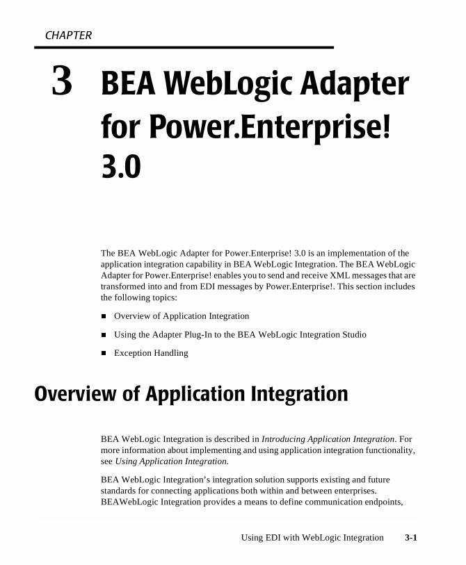
8. Set the connection criteria based on your requirements. Many of these criteria areautomatically generated based on the information you have already entered andyour system configuration. When you are finished, select Continue. The DeployApplication View window appears.
3 BEA WebLogic Adapter for Power.Enterprise! 3.0
3-6 Using EDI with WebLogic Integration
Figure 3-4 Deploy Application View JSP
9. Set any parameters necessary, and select Deploy. Your configured applicationview is deployed.
Note: Always start the Power.Server! before you start WebLogic Integration orWebLogic Server. The WebLogic Integration connectors expect to see anactive instance of the Power.Server! when they are initialized, and they willthrow exceptions if Power.Server! is not running when they are initialized.
Events
An event contains an XML document that is published by an application view whenan event of interest occurs. Clients that want to be notified of events register theirinterest with an application view. After a client subscribes to events published by anapplication view, the application view notifies the client whenever a subscribed eventoccurs within the target application, and then passes the client an XML document that

Overview of Application Integration
Using EDI with WebLogic Integration 3-7
describes the event. For more information about events, see “Adding and Event to anApplication View” in “Defining an Application View” in Using ApplicationIntegration.
The BEA WebLogic Adapter for Power.Enterprise! provides user-definable events.These events are created and managed using a Java Server Page, which is published aspart of the WebLogic Integration Application Interface. When Power.Enterprise!receives an EDI message from a trading partner and forwards it to the BEA WebLogicAdapter for Power.Enterprise!, the Adapter publishes the appropriate events. Theprocess works as follows:
1. Upon receipt of an EDI document from a trading partner, Power.Enterprise!translates the document to XML.
2. Using RMI, Power.Enterprise! invokes BEA WebLogic Adapter forPower.Enterprise! with a previously registered event.
3. WebLogic Integration publishes the defined event.
Configuring Events
Events are used by the BEA WebLogic Adapter for Power.Enterprise! to sendinformation from a workflow to Power.Enterprise!, which forwards it to your tradingpartner. The BEA WebLogic Adapter for Power.Enterprise! allows you to definemultiple events. As a rule, you will define one event per XML/EDI document type (apurchase order, for example) that you plan to send.
To define an event on the BEA WebLogic Adapter for Power.Enterprise!:
1. On the BEA WebLogic Adapter for Power.Enterprise! home page, click AddEvent.

3 BEA WebLogic Adapter for Power.Enterprise! 3.0
3-8 Using EDI with WebLogic Integration
Figure 3-5 Configure Event JSP
2. Enter a name for the event that is unique within the BEA WebLogic Adapter forPower.Enterprise!.
3. If you like. Enter a description. (This step is optional.)
4. Enter the hostname or IP address of the system on which the Power.Server!process resides.
5. Enter the number of the port used by the RMI listener process.
6. Enter the RMI service name of the listener process as defined forPower.Enterprise!.
Overview of Application Integration
Using EDI with WebLogic Integration 3-9
Testing an Event
After you configure both events and your workflows, you should test that you cansuccessfully send messages through those events. Use the Test Event link to test yourevent within the Application View console.
The following procedure is a simple test method to test how an event receives amessage:
1. Configure Power.Enterprise! such that it temporarily uses a file connection to sendto your trading partner.
2. Send a message through the system, and dump the resulting EDI message to afile.
3. Examine the file containing the message to make sure that the message wascreated and sent correctly.
4. When you finish testing, reconfigure the connection to use the transportappropriate to your trading partner.
Services
A service is a business operation in an application that is exposed by the applicationview. It functions as a request/response mechanism: when an application receives arequest to invoke a business service, the application view invokes that functionality inits target application and then responds with an XML document that describes theresults. For more information about services, see “Adding a Service to an ApplicationView” in “Defining an Application View” in Using Application Integration.
The BEA WebLogic Adapter for Power.Enterprise! provides user-configurableservices. These services are created and managed using a Java Server Page, which ispublished as part of the WebLogic Integration Application Interface. They are used tosend XML to Power.Enterprise!, which, in turn, converts the XML message to an EDImessage and sends the EDI message to a trading partner.
To send an EDI message, submit an appropriately formatted XML document to theservice defined for BEA WL Adapter for Power.Enterprise!. The service uses RMI topass the message to Power.Enterprise!, which translates the XML message to an EDImessage format and dispatches it to the appropriate trading partner.

3 BEA WebLogic Adapter for Power.Enterprise! 3.0
3-10 Using EDI with WebLogic Integration
Configuring Services
Services are used by the BEA WebLogic Adapter for Power.Enterprise! to receiveinformation for a workflow that is forwarded from your trading partner byPower.Enterprise!. Although the BEA WebLogic Adapter for Power.Enterprise!allows you to define multiple services, most situations require you to define only oneevent per XML/EDI document type (such as an EDI 855 message) that you plan toreceive.
To define a service on the BEA WebLogic Adapter for Power.Enterprise!:
1. On the BEA WebLogic Adapter for Power.Enterprise! home page, click AddService. The Configure Service JSP is displayed.
Figure 3-6 Configure Service JSP
2. Enter a name for the service that is unique within the BEA WebLogic Adapter forPower.Enterprise!.
Using the Adapter Plug-In to the BEA WebLogic Integration Studio
Using EDI with WebLogic Integration 3-11
3. Enter a description. (This step is optional.)
4. Enter the name of the RMI source connection, defined under Power.Enterprise!,from which this service can expect to receive messages.
Testing a Service
After you configure both services and the workflows that will use those services, youshould verify that you can properly receive messages from them. Use the Test Servicelink to test your event within the Application View console.
The following procedure is a simple test method to test how a service delivers amessage:
1. Configure Power.Enterprise! such that it temporarily uses an inbound fileconnection.
2. Drop a file into an outbox to start a test sequence. The resulting message shouldbe transformed by Power.Enterprise, then sent to your workflow.
3. In your workflow, examine the message to make sure that it was created andreceived correctly.
4. When you finish testing, reconfigure the connection to use the transportappropriate to your trading partner.
Using the Adapter Plug-In to the BEA WebLogic Integration Studio
The BEA WebLogic Adapter for Power.Enterprise! includes a plug-in to the BEAWebLogic Integration Studio, a graphical tool for modeling for business processes.Because the Adapter is an integral part of BEA WebLogic Integration, you can use thisplug-in for EDI message handling and integration in exactly the same way you use anyother application integration adapter.

3 BEA WebLogic Adapter for Power.Enterprise! 3.0
3-12 Using EDI with WebLogic Integration
For more information about BPM workflow design using adapters and the adapterplug-in to the BEA WebLogic Integration Studio, see “Understanding the ApplicationIntegration Plug-in for BPM” and “Understanding the ADK” in IntroducingApplication Integration.
Deploying an Adapter in a New WebLogic Integration Domain
If you want to deploy an instance of the BEA WebLogic Adapter for Power.Enterprise!3.0 in a new domain, follow these steps:
For Windows Systems:
Before you begin, you must determine the location of the adapter ear and jar file onyour computer. By default, they are located inWLI_HOME\adapters\powerenterprise\lib.
1. Declare the adapter's EAR file in your domain's config.xml file.
Listing 3-1 Windows Config.XML Domain Declaration
<Application Deployed="true" Name="BEA_POWERENTERPRISE_3_0"Path="WLI_HOME\adapters\powerenterprise\lib\BEA_POWERENTERPRISE_3_0_EAR.ear">
<ConnectorComponent Name="BEA_POWERENTERPRISE_3_0"Targets="myserver" URI="BEA_POWERENTERPRISE_3_0.rar"/><WebAppComponent Name="BEA_POWERENTERPRISE_3_0_EventRouter"Targets="myserver"URI="BEA_POWERENTERPRISE_3_0_EventRouter.war"/><WebAppComponent Name="BEA_POWERENTERPRISE_3_0_Web"Targets="myserver" URI="BEA_POWERENTERPRISE_3_0_Web.war"/>
</Application>
2. Add the following JAR files in the WebLogic server classpath.
WLI_HOME\lib\hlcommon.jar
WLI_HOME\lib\mekshared.jar
WLI_HOME\lib\powerapi.jar

Exception Handling
Using EDI with WebLogic Integration 3-13
WLI_HOME\adapters\powerenterprise\lib\BEA_POWERENTERPRISE_3_0.jar
For UNIX Systems
Before you begin, you must determine the location of the adapter ear and jar file onyour computer. By default, they are located inWLI_HOME/adapters/powerenterprise/lib.
1. Declare the adapter's EAR file in your domain's config.xml file:
Listing 3-2 UNIX Config.XML Domain Declaration
<Application Deployed="true" Name="BEA_POWERENTERPRISE_3_0"Path="WLI_HOME/adapters/powerenterprise/lib/BEA_POWERENTERPRISE_3_0_EAR.ear">
<WebAppComponent Name="BEA_POWERENTERPRISE_3_0_EventRouter"Targets="myserver" URI="BEA_POWERENTERPRISE_3_0_EventRouter.war"/>
<ConnectorComponent Name="BEA_POWERENTERPRISE_3_0" Targets="myserver"URI="BEA_POWERENTERPRISE_3_0.rar"/>
<WebAppComponent Name="BEA_POWERENTERPRISE_3_0_Web"Targets="myserver"URI="BEA_POWERENTERPRISE_3_0_Web.war"/>
</Application>
2. Add the following JAR files in the WebLogic Server classpath.
WLI_HOME/lib/hlcommon.jar
WLI_HOME/lib/mekshared.jar
WLI_HOME/lib/powerapi.jar
WLI_HOME/adapters/powerenterprise/lib/BEA_POWERENTERPRISE_3_0.jar
Exception Handling
The response schema for a service method should include both a status Code and aMessage:

3 BEA WebLogic Adapter for Power.Enterprise! 3.0
3-14 Using EDI with WebLogic Integration
� Code returns Success or Failure.
� Message corresponds to a message returned by Power.Enterprise! when aservice call is initiated.
To handle any exception that may occur, create an XPath expression to retrieve thestatus code from any response XML.
The following is an example of the response schema for a service call:
<Status>
<Code>Success </Code>
<Message>Translation Request Queued Successfully.</Message>
</Status>
The Code can be extracted from the response schema using the following Xpathexpression:
"/Status/Code/text()".
Using EDI with WebLogic Integration 4-1
CHAPTER
4 Configuring Power.Enterprise!
This section describes the installation and configuration of Power.Enterprise! and itsassociated software:
� Installing Power.Enterprise!
� Configuring Power.Enterprise!
� Configuring Trading Partners
� Mapping XML and EDI Data
� Connections and VAN Connectivity
� Configuring Exchange Profiles
Installing Power.Enterprise!
Power.Enterprise! is delivered in two packages that must be installed separately. Inaddition, you may want to install Cleo A+ to manage VAN connectivity issues.
If you plan to install both Power.Server! and Power.Client! on the same machine, youmust install them in separate directories.
� Power.Server! is the run-time server. Before you can install this package, yourenvironment must meet the following prerequisites:

4 Configuring Power.Enterprise!
4-2 Using EDI with WebLogic Integration
� Operating System: Microsoft Windows NT 4.0 SP6, Windows 2000 SP1,Sun Solaris 7, HP UX 11, or IBM AIX 4.3.3
� Java: Sun JRE/JDK 1.3 or later
� Memory: 512MB minimum, 1GB recommended
� Disk space: 100MB
� SQL Database: Power.Server! requires access to an SQL database.Power.Server! supports Oracle 8i, Microsoft SQL Server 2000, and IBMDB2 version 7.1.You must provide the hostname, connection port, databasename, and login information for the database during installation.
BEA WebLogic Integration includes a 30-day trial license common to allPower.Enterprise! software. To receive a single, full-use license forPower.Server!, contact your BEA sales representative. One Power.Enterprise!license is available for each BEA WebLogic Integration license.
� Power.Client! contains Power.Map! and Power.Manager!. Before you can installthis package, your environment must meet the following prerequisites:
� Operating System: Microsoft Windows NT 4.0 SP4 or Windows 2000
� Java: Sun JRE/JDK 1.3 or later
� Memory: 256MB
� Disk space: 50MB
� Internet Explorer 5.0
BEA WebLogic Integration includes a 30-day trial license common to allPower.Enterprise! software. Power.Client! uses this license key
� Cleo A+ is an asynchronous communications management package used tocontrol VAN communications with your trading partner. If you are using a VANother than Get2Connect, and you need asynchronous communicationsmanagement, install the Cleo A+ software. For more information about installingCleo A+, go to the following URL:
http://www.cleo.com/install/peregrine/install.htm
For information about obtaining a production license for Cleo A+, contact CleoCommunications.

Installing Power.Enterprise!
Using EDI with WebLogic Integration 4-3
Getting Licenses
Whether you download Power.Enterprise! as part of the WebLogic Integration 2.1installation or install it from CD media, you will need to obtain your Power.Enterprise!3.0 evaluation license from the BEA website at the following URL:
http://commerce.bea.com/downloads/weblogic_integration.jsp
A Power.Enterprise! production license is provided when you purchase BEAWebLogic Integration. For more information, please contact your BEA salesrepresentative.
In addition, you may download and install a 30-day trial of Cleo A+, for handling VANconnectivity. To convert your trial license to a production license, contact CleoCommunications.
Access to the Get2Connect.Net VAN is included with the BEA WebLogic Adapter forPower.Enterprise!. To use Get2Connect.Net, contact Peregrine Customer Supportthrough their Web site at http://www.peregrine.com/.
Installing the Power.Server!
To install the Power.Server! software, you must fulfill the prerequisites listed in theprevious sections of this document. For general information about installingPower.Server!, see “Installing the Power.Enterprise! Software” in Installing BEAWebLogic Integration.
Installing the Power.Client!
To install the Power.Client! software (specifically Power.Map! and Power.Manager!),you must fulfill the prerequisites listed under “Installing Power.Enterprise!” on page4-1. For general information about installing Power.Map! and Power.Manager!, see“Installing the Power.Enterprise! Software” in Installing BEA WebLogic Integration.

4 Configuring Power.Enterprise!
4-4 Using EDI with WebLogic Integration
Connecting to Get2Connect.Net
To use Get2Connect.Net, you must have the Power.Enterprise! software installed. Youmust also have a valid Product Serial Number (PSN) to register as a Get2Connect.Nettrading partner. To get a valid PSN, contact BEA Customer Support.
Installing Cleo A+
If you intend to use Cleo A+ for VAN communications, go to the following URL:
http://www.cleo.com/install/peregrine/install.htm
This Web page provides downloadable installation sets for all platforms supported byPower.Server!, as well as installation and user documentation. The downloadablesoftware includes a trial license. For production licensing, contact CleoCommunications.
Downloading Software Updates
Power.Enterprise! is designed to be updated with downloaded software patches fromthe BEA Customer Service Web site.
To install software patches for Power.Enterprise!:
1. From within Power.Manager! click Self Service, then click Software Update.
2. Click Step 1: Select Software. This launches a Web browser which automaticallyconnects to the BEA Customer Service web page, listing all software update filesavailable for download. Instructions for installation of these updates are alsoincluded on this Web page.
Updating EDI Document Descriptions
Power.Enterprise! ships with definitions for many standard EDI documents included.BEA will also make new definition sets available through BEA Customer Service.

Installing Power.Enterprise!
Using EDI with WebLogic Integration 4-5
To install new standards downloaded from the BEA Customer Service Web site:
1. From within Power.Manager! click Self Service, then click Standards Update.
2. Click Step 1: Select Standards. This launches a Web browser whichautomatically connects to the BEA Customer Service web page, listing all EDIdefinition files available for download.
3. Select and download the EDI definition files that you require.
4. Place the downloaded files into the following directory:
Power_Server_install_dir\downloads\metadata\
5. Stop, then restart the Power.Server on which you have installed the definitionfile.
6. Remove the downloaded files from the following directory:
Power_Server_install_dir\downloads\metadata\
7. To access the document descriptions from within Power.Map!, check them outfrom the server.
Connecting to a Server for the First Time
Before you can log in to Power.Manager! or Power.Map!, you must create aPower.Server! connection. Subsequently, you can use the same procedure to connectto other instances of Power.Server!, allowing you to manage multiple instances ofPower.Server! from a single console. All connection data is persistent: once you createa connection, it will be available every time you start Power.Manager!.
To create a connection:
1. Log in to Power.Manager! or Power.Map by choosingStart Menu→Programs→Power.It. Select the appropriate application. To create aserver connection, Power.Server! must be running on the machine to which youwant to connect.
4 Configuring Power.Enterprise!
4-6 Using EDI with WebLogic Integration
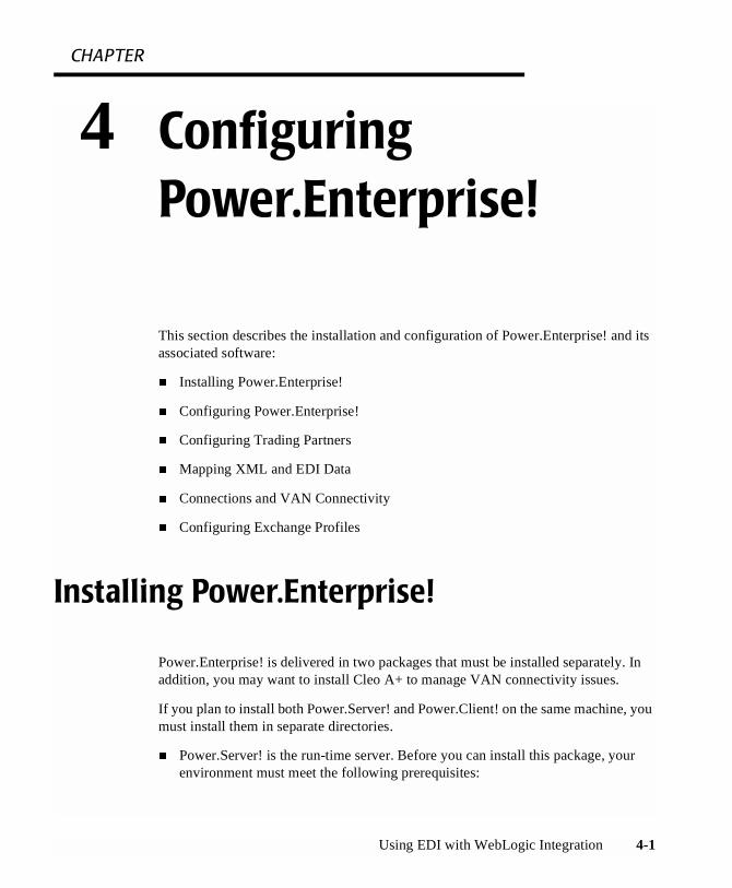
Figure 4-1 Power.Manager! Server Connection Dialog Box
2. Click Add to add a new Power.Server! connection.
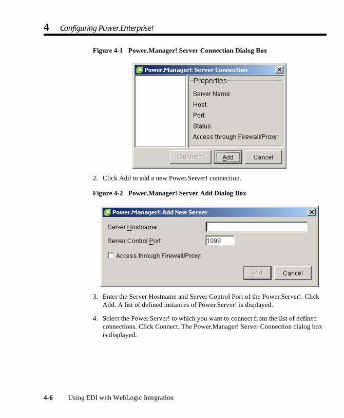
Figure 4-2 Power.Manager! Server Add Dialog Box
3. Enter the Server Hostname and Server Control Port of the Power.Server!. ClickAdd. A list of defined instances of Power.Server! is displayed.
4. Select the Power.Server! to which you want to connect from the list of definedconnections. Click Connect. The Power.Manager! Server Connection dialog boxis displayed.

Configuring Power.Enterprise!
Using EDI with WebLogic Integration 4-7
Figure 4-3 Power.Manager! Server Connection Dialog Box
Configuring Power.Enterprise!
Power.Enterprise! allows you to configure multiple connections to the BEA WebLogicAdapter for Power.Enterprise!. Each connection to the BEA WebLogic Adapter forPower.Enterprise! is defined as a separate RMI connection, either sending data to orreceiving data from Power.Enterprise!. All other configuration required byPower.Enterprise! is designed to configure trading partners, maps, externalconnections, and exchange profiles. When initially configuring Power.Enterprise!, besure to configure the following entities in the order shown:
� Trading partners
� Maps
� Connections
� Exchange profiles

4 Configuring Power.Enterprise!
4-8 Using EDI with WebLogic Integration
Configuring Trading Partners
To use EDI Integration with WebLogic Integration, you must enter your tradingpartner data into both Power.Enterprise! and WebLogic Integration. No mechanismexists to move trading partner data either to or from Power.Enterprise!, so you anytrading partner data registered with WebLogic Integration must also be entered intoPower.Enterprise!.
You must create a Power.Enterprise! trading partner profile for every trading partnerinvolved in your transactions, including your own company.
To create a new trading partner:
1. Start Power.Manager!. A list of defined instances of Power.Server! is displayed.
2. Select the instance of Power.Server! to which you want to connect. (If noPower.Server! connections are defined, see “Connecting to a Server for the FirstTime” on page 4-5.)
Figure 4-4 Power.Manager! Server Connection Dialog Box
3. Click Connect. The Power.Manager! main window is displayed.

Configuring Trading Partners
Using EDI with WebLogic Integration 4-9
Figure 4-5 Power.Manager!
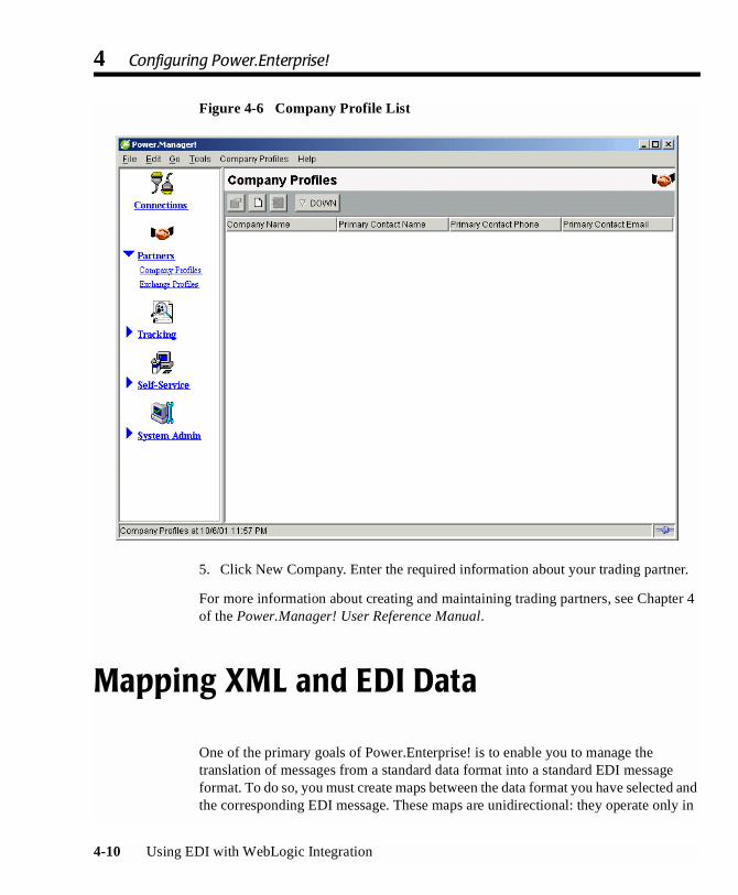
4. To set up a trading partner’s company profile, choose Partners→CompanyProfiles. The Company Profile window is displayed.
4 Configuring Power.Enterprise!
4-10 Using EDI with WebLogic Integration
Figure 4-6 Company Profile List
5. Click New Company. Enter the required information about your trading partner.
For more information about creating and maintaining trading partners, see Chapter 4of the Power.Manager! User Reference Manual.
Mapping XML and EDI Data
One of the primary goals of Power.Enterprise! is to enable you to manage thetranslation of messages from a standard data format into a standard EDI messageformat. To do so, you must create maps between the data format you have selected andthe corresponding EDI message. These maps are unidirectional: they operate only in

Mapping XML and EDI Data
Using EDI with WebLogic Integration 4-11
one direction. Thus, if you need to be able to translate data back and forth between aparticular XML message format and a specific EDI message format, you must createtwo maps: one for outbound transformation (XML to EDI) and one for inboundtransformation (EDI to XML).
Fortunately, creating such maps is not a difficult task. Power.Map! can understand avariety of standard document definitions, including flat files, database tables, XML,and all the major EDI formats (X12, EDIFACT, and TRADACOMS). As used withinPower.Map!, a document definition is an element-by-element description of adocument, its structure, and the data carried within it. Thus, you can use standarddocument definitions to outline your maps, then simply connect the individual dataelements between two document definitions using a drag-and-drop interface.
Figure 4-7 Power.Map! Main Window

4 Configuring Power.Enterprise!
4-12 Using EDI with WebLogic Integration
For more information about creating maps, see the Power.Map! User ReferenceManual.
You may work on maps without being connected to a Power.Server! instance. If youtry to use any repository commands, however, the Server Connection dialog box isdisplayed, requiring you to connect to a server instance so the repository command canbe run. To define a server connection, see “Connecting to a Server for the First Time”on page 4-5.
At any time, you can save a copy of the map you have created on your local system.Choose File→Save, then enter a descriptive name for the map file in the dialog box. Themap is stored as a jar file.
Before you can use a map in production, you must promote the map to your server.Select the Finish tab, then click Promote at the bottom of the tab to send the map to theserver. If you are not already connected to the server, you must establish a connectionbefore you can promote the map.
Connections and VAN Connectivity
Connections define how message traffic is delivered, both into and out of thePower.Server!. Before you can use the BEA WebLogic Adapter for Power.Enterprise!,you must configure a minimum of four connections:
� Source RMI connection that receives messages from the BEA WebLogicAdapter for Power.Enterprise!
� Target RMI connection that sends messages from the Power.Server! to the BEAWebLogic Adapter for Power.Enterprise!
� Target connection that sends messages from the Power.Server! to your tradingpartner
� Source connection that receives messages from your trading partner
Two of these connections, the source and target RMI connections, are used tocommunicate with BEA WebLogic Integration. These two connections are used by allEDI transactions.
Connections and VAN Connectivity
Using EDI with WebLogic Integration 4-13
Creating RMI Connections
To set up the source and target RMI connections:
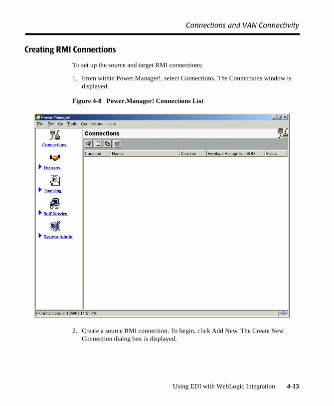
1. From within Power.Manager!, select Connections. The Connections window isdisplayed.
Figure 4-8 Power.Manager! Connections List
2. Create a source RMI connection. To begin, click Add New. The Create NewConnection dialog box is displayed.

4 Configuring Power.Enterprise!
4-14 Using EDI with WebLogic Integration
Figure 4-9 Create New Connection Dialog Box
3. Set the name to BEASource, the Transport to RMI, and the Direction to Source.Click OK. The Connection Properties dialog box is displayed.
Figure 4-10 Inbound RMI Properties
4. Set Status to Active and Envelope Recognition BDD to XMLEnvelope. ClickOK.
5. Create an outbound RMI connection. To begin, click Add New. The Create NewConnection dialog box is displayed.

Connections and VAN Connectivity
Using EDI with WebLogic Integration 4-15
6. Set the name to BEATarget, the Transport to RMI, and the Direction to Target.Click OK. The Connection Properties dialog box is displayed.
Figure 4-11 Outbound RMI Properties
7. Set Status to Active, Target to localhost, and Service Name to edi. Click OK.
Creating Trading Partner Connections
The other two connections, the inbound and outbound trading partner connections, arespecific to each trading partner. Therefore, you must define a unique pair ofconnections for each trading partner. When you set up each pair, you must select thetransport that you and your trading partner will use. We recommend the followingtransport options:
� HTTP: A standard HTTP/HTTPS transport protocol for exchanging EDImessages with your trading partner
� File: Option that writes the EDI message to a file, or reads the message from afile. You are responsible for providing a transport mechanism from this point inthe process.
� FTP: Option that uses an FTP server to exchanges messages with your tradingpartner.

4 Configuring Power.Enterprise!
4-16 Using EDI with WebLogic Integration
� Get2Connect: A VAN operated by Peregrine Systems. Connectivity to this VANis included with the Power.Enterprise! software, however you must contactPeregrine Systems to sign up to use the Get2Connect VAN.
� Use Cleo A+ if you intend to connect via a VAN that requires asynchronouscommunications. For more information, see “VAN and Network Connectivity,”in Chapter 2, “Architecture.”
Other connection options are also available. For details about all options, see Chapter3 of the Power.Manager! User Reference Manual.
Configuring Exchange Profiles
The exchange profile specifies how a trading partner exchanges messages throughPower.Server!. Because Power.Server! is an EDI gateway, it is not the final point ofreceipt for a message. An exchange profile describes how Power.Server! receives amessage, transforms it, and sends it to its destination. For example, an exchange profilemight define the receipt of an EDI message from a trading partner, its transformationinto an XML message, and its delivery to the BEA WebLogic Adapter forPower.Enterprise!.
Exchange profiles cannot be created unless certain prerequisite information has beendefined. Specifically, you must have created and promoted to the server your exchangemaps, your trading partner profile, and both the source and target connections. (Thesource and target connections post messages to Power.Server! and receive messagesfrom Power.Server!, respectively.) For example, to create an exchange profile thatallows you to send a message to your trading partner, you need the following:
� XML-to-EDI-transaction map for the EDI message you plan to send
� Your trading partner profile
� BEAOutbound RMI connection you created in “Connections and VANConnectivity” on page 4-12
� Outbound connector to your trading partner
Other information is also required. For details, see Chapter 4 of the Power.Manager!User Reference Manual. For examples of both inbound and outbound exchangeprofiles, see Chapter 6, “EDI Sample,” in this document.
Using EDI with WebLogic Integration 5-1
CHAPTER
5 Configuring EDI Integration
BEA WebLogic EDI Integration must be completely configured before it can be used.Because EDI Integration depends on the Power.Enterprise! software to properlyoperate, you must properly configure Power.Enterprise! before you can communicatewith your trading partners.
General Configuration
This section discusses the general configuration information that you should performbefore attempting to configure a specific document exchange with a trading partner.

5 Configuring EDI Integration
5-2 Using EDI with WebLogic Integration
Configure Trading Partners
Before configuring individual transactions, you should configure all trading partners,including your own company, using Power.Manager!. For more information aboutconfiguring trading partners, see the following topics:
� “Configuring Trading Partners” on page 4-8
� Chapter 4, “Partners,” in the Power.Manager! User Reference Manual
Configure VAN/Trading Partner Connectivity
You should also configure your trading partner connectivity before attempting toconfigure individual document exchanges. See the following topics:
� “Connections and VAN Connectivity” on page 4-12
� Chapter 3, “Connections,” in the Power.Manager! User Reference Manual
Although you may not want to set up connectivity to your production trading partnersat this time, you may want to configure them with file connectors for development andtesting purposes.
Configuring EDI Integration to Receive an EDI Document
This section describes how to configure EDI Integration so that the BEA WebLogicAdapter for Power.Enterprise! 3.0 can receive an EDI document and send it to theWebLogic Integration process engine as an XML document.
Configuring EDI Integration to Receive an EDI Document
Using EDI with WebLogic Integration 5-3
Pre-Planning
� Determine the EDI standard, version, and document type that you will receive.For example, you might select an X12 850 document v4010, which is an X12standard, 850 type document, version 4010.
� Define the XML format that you will use internally. This XML format shouldcontain a complete data map of the fields in the EDI document that you will use.
� Create a DTD and an XSD for the XML document. You must create bothbecause Power.Enterprise! and WebLogic Integration do not use the same datafile format for this step. WebLogic Integration requires an XSD (if you supplyone at all), while Power.Enterprise! requires a DTD. You should note thatPower.Enterprise! does not provide any export utility to export a DTD or XSDfrom a map definition once the DTD or XSD has been imported. You will beresponsible for creating both the DTD and XSD files.
Within Power.Enterprise!
� Create a map between the XML document and the EDI document. Import theDTD into Power.Map! to load the XML document standard. The appropriateEDI document should already exist in the Power.Server! repository. If the EDIdocument is not present, contact BEA Customer Support. For more informationabout how to do this, see the following topics:
� “Mapping XML and EDI Data” on page 4-10
� Chapter 3, “Maps” in the Power.Map! User Reference Manual
� Define an inbound connection. This connection should use your trading partner’sconnection protocol, which you should have already defined. See “Connectionsand VAN Connectivity” on page 4-12 for more information.
� Define an RMI target connection. This connection is used to communicate withthe WebLogic Integration process engine.
� Define an exchange profile, using the procedure discussed in “ConfiguringExchange Profiles” on page 4-16. This exchange profile should connect theinbound connection from your trading partner to the RMI target connection.

5 Configuring EDI Integration
5-4 Using EDI with WebLogic Integration
Within BEA WebLogic Integration
� Create an application view, using the procedure in “Configuring the BEAWebLogic Adapter for Power.Enterprise!.”
� Create an event for the application view you just created, using the procedure in“Configuring Events” on page 3-7. Be sure to set the following parameters:
� Event Name: The name of the event. The name should be descriptive (forexample, ReceivePurchaseOrder)
� Event Description: Text description of the event
� RMI Service Name: This should match the RMI service name defined in thePower.Enterprise! RMI target connection setup in the previous section.
� XSD: The XML schema of the XML message to be received (optional)
� XML Root Element: The XML root element of the XML schema (optional)
� Deploy the application view you have created and defined.
Verify that the Power.Server! instance is running. At this point, the application viewshould be available to the WebLogic Integration process engine using the applicationintegration plug-in. For more information about the application integration plug-in, see“Understanding the Application Integration Plug-In for BPM” in IntroducingApplication Integration.
Note: Always start the Power.Server! before you start WebLogic Integration orWebLogic Server. The WebLogic Integration connectors expect to see thePower.Server! running when they are initialized, and they throw exceptions ifPower.Server! is not running when they are initialized.
Configuring EDI Integration to Send an EDI Document
Using EDI with WebLogic Integration 5-5
Configuring EDI Integration to Send an EDI Document
This section describes how to configure EDI Integration to send an EDI documentusing an XML document in the WebLogic Integration process engine as the source.
Pre-Planning
� Determine the EDI standard, version, and document type that you will receive.For example, you might select an X12 850 document v4010, which is anX12-standard, 850-type document, version 4010.
� Define the XML format that you will use internally. This XML format shouldcontain a complete data map of the fields in the EDI document that you will use.
� Create a DTD and an XSD for the XML document. You must create bothbecause Power.Enterprise! and WebLogic Integration do not use the same datafile format for this step. WebLogic Integration requires an XSD (if you supplyone at all), while Power.Enterprise! requires a DTD. You should note thatPower.Enterprise! does not provide any export utility to export a DTD or XSDfrom a map definition once the DTD or XSD has been imported. You areresponsible for creating both the DTD and XSD files.
Within Power.Enterprise!
� Create a map between the XML document and the EDI document. Import theDTD into Power.Map! to load the XML document standard. The appropriateEDI document should already exist in the Power.Server! repository. If the EDIdocument is not present, contact BEA Customer Support. For more informationabout how to do this, see the following topics:
� “Mapping XML and EDI Data” on page 4-10
� Chapter 3, “Maps” in the Power.Map! User Reference Manual
� Define an outbound connection. This connection should use your tradingpartner’s connection protocol, which you should have already defined. See“Connections and VAN Connectivity” on page 4-12 for more information.
5 Configuring EDI Integration
5-6 Using EDI with WebLogic Integration
� Define an RMI source connection. This connection is used to communicate withthe WebLogic Integration process engine.
� Define an exchange profile, using the procedure discussed in “ConfiguringExchange Profiles” on page 4-16. This exchange profile should connect the RMIsource connection to your trading partner’s outbound connection.
Within BEA WebLogic Integration
� Create an application view, using the procedure in “Configuring the BEAWebLogic Adapter for Power.Enterprise!” on page 3-3 in this document.
� Create service for the application view you just created, using the procedure in“Configuring Services” on page 3-10 in this document. Be sure to set up thefollowing parameters:
� Service Name: The name of the service. The name should be descriptive (forexample, SendPurchaseOrder).
� Service Description: Text description of the service.
� Connection Name: This name should match the RMI service name defined inthe Power.Enterprise! RMI source connection setup, described in theprevious section.
� XSD: The XML schema of the XML message to be sent. (optional)
� XML Root Element: The XML root element of the XML schema. (optional)
� Deploy the application view you have created and defined.
Verify that the Power.Server! instance is running. At this point, the application viewshould be available to the WebLogic Integration process engine using the applicationintegration plug-in. For more information about the application integration plug-in, see“Understanding the Application Integration Plug-In for BPM” in IntroducingApplication Integration.

Using EDI with WebLogic Integration 6-1
CHAPTER
6 EDI Sample
This section describes the configuration and operation of the EDI sample. Because theEDI sample relies on the proper configuration of Power.Server!, you must configurePower.Server! before you can run the sample. (Such configuration is not a requirementfor running the other samples provided with BEA WebLogic Integration.)
It includes the following topics:
� Sample Overview
� Setting up and Running the Sample
Sample Overview
The EDI sample contains a simple Purchase Order business process. Two tradingpartners are involved:
� Buyer: Advanced Networks Inc. (ANI)
� Supplier: General Control Systems (GCS)
Advanced Networks buys control system components from General Controls. ANIuses EDI to send Purchase Orders to GCS and to receive Purchase OrderAcknowledgments from Supplier GCS.
The Sample is based on the assumption that Supplier GCS uses BEA WebLogicIntegration as its Business to Business Integration solution, that is, as the frameworkin which it exchanges EDI documents with its trading partners. The architecture of theWebLogic EDI Integration is shown in the following figure.
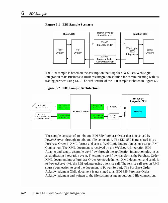
6 EDI Sample
6-2 Using EDI with WebLogic Integration
Figure 6-1 EDI Sample Scenario
The EDI sample is based on the assumption that Supplier GCS uses WebLogicIntegration as its Business to Business integration solution for communicating with itstrading partners using EDI. The architecture of the EDI sample is shown in Figure 6-2.
Figure 6-2 EDI Sample Architecture
The sample consists of an inbound EDI 850 Purchase Order that is received byPower.Server! through an inbound file connection. The EDI 850 is translated into aPurchase Order in XML format and sent to WebLogic Integration using a target RMIConnection. The XML document is received by the WebLogic Integration EDIAdapter and sent to a sample workflow through the application integration plug-in asan application integration event. The sample workflow transforms the Purchase OrderXML document into a Purchase Order Acknowledgment XML document and sends itto Power.Server! via the EDI Adapter using a service call. The service call uses an RMIsource connection to send the document to Power.Server!. The Purchase OrderAcknowledgment XML document is translated to an EDI 855 Purchase OrderAcknowledgment and written to the file system using an outbound file connection.

Setting up and Running the Sample
Using EDI with WebLogic Integration 6-3
Setting up and Running the Sample
This section lists the prerequisites for executing the BEA WebLogic Integration EDIsample and instructions for running it.
Prerequisites
Before you run the EDI sample, you must install all product components of BEAWebLogic Integration, including:
� BEA WebLogic Server 6.1
� BEA WebLogic Integration 2.1
� Power.Enterprise! 3.0 (including Power.Server!, Power.Manager!, andPower.Map!)
Hardware and OS Requirements
Because the EDI sample is based on the assumption that you have access, on a singlemachine, to all of the software, including Power.Server!, Power.Manager!, andPower.Map!, the OS installation requirements are more restrictive than those for aproduction environment.
� Minimum memory available: 512 MB
� OS: Windows NT 4.0 with Service Pack 6 or Windows 2000 withService Pack 1
Configuring the EDI Sample
Configuration and execution of the EDI sample require you to perform the followingsteps:

6 EDI Sample
6-4 Using EDI with WebLogic Integration
Step 1: Start Power.Server!
Step 2: Start Power.Manager! and Configure Partners
Step 3: Start Power.Map! and Load Maps and Adapters
Step 4: Set Up the Connections
Step 5: Set Up the Exchange Profiles
Step 6: Set Up the Workflow
Step 7: Deploy the Application View
Step 8: Run the Sample
The following files are available in WLI_HOME/samples/EDISample.
� Readme.txt
� WLI_EDI_SAMPLE.pdf
� XMLEnvelope.jar
� EDI850toPOXML.jar
� POAckXMLtoEDI855.jar
� EDISampleWorkflow.jar
� Edi850.edi
Note: Always start the Power.Server! before you start WebLogic Integration orWebLogic Server. The WebLogic Integration connectors expectPower.Server! to be running when they are initialized, and they throwexceptions if Power.Server! is not running when they are initialized.
Step 1: Start Power.Server!
Start Power.Server! by selecting Start Menu→Programs→Power.It→Power.Server!.Wait approximately 10 seconds for the server to start.
Step 2: Start Power.Manager! and Configure Partners
1. Start Power.Manager! by selectingStart Menu→Programs→Power.It→Power.Manager!.
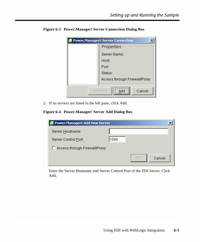
Setting up and Running the Sample
Using EDI with WebLogic Integration 6-5
Figure 6-3 Power.Manager! Server Connection Dialog Box
2. If no servers are listed in the left pane, click Add.
Figure 6-4 Power.Manager! Server Add Dialog Box
Enter the Server Hostname and Server Control Port of the EDI Server. ClickAdd.

6 EDI Sample
6-6 Using EDI with WebLogic Integration
3. Select the Power.Server! to which you want to connect and click Connect.
Figure 6-5 Power.Manager! Server Connection Dialog Box
The Power.Manager! main window is displayed.

Setting up and Running the Sample
Using EDI with WebLogic Integration 6-7
Figure 6-6 Power.Manager!
4. Set up the company profiles. Click Partners, then click Company Profiles.

6 EDI Sample
6-8 Using EDI with WebLogic Integration
Figure 6-7 Company Profile List
5. Create a Company Profile for GCS. Click the New Company icon .
The Company Properties dialog box is displayed.

Setting up and Running the Sample
Using EDI with WebLogic Integration 6-9
6. Add the required information about GCS.
Figure 6-8 Company Properties Dialog Box for a New Company Profile
7. Create a Company Profile for AES. Click the New Company icon .
8. When the Company Properties dialog box is displayed, enter the requiredinformation about AES.
Step 3: Start Power.Map! and Load Maps and Adapters
1. Start Power.Map! by choosing Start Menu→Programs→Power.It→Power.Map!.
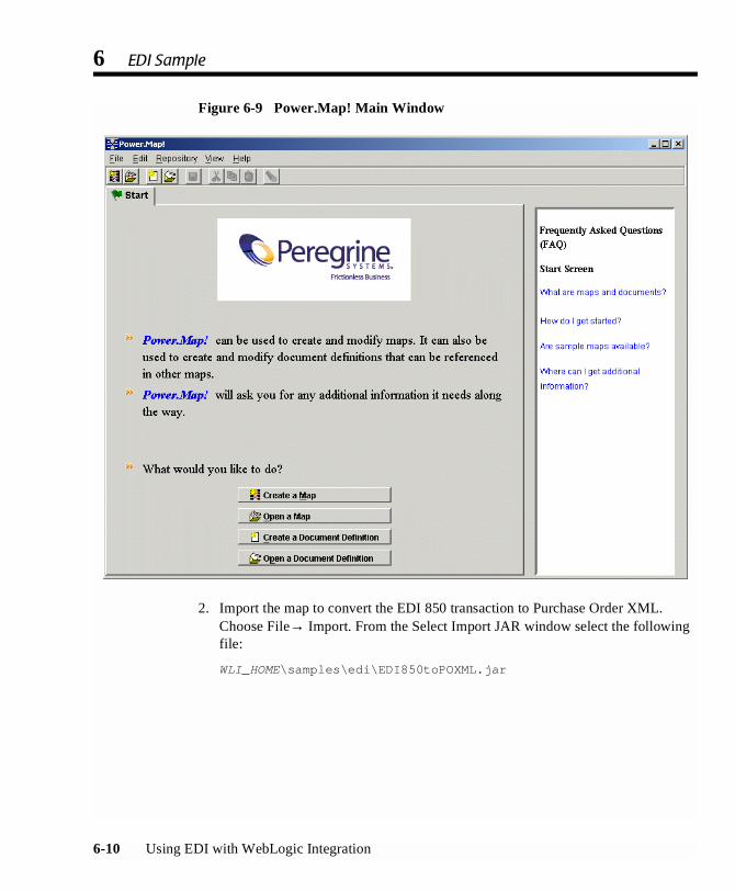
6 EDI Sample
6-10 Using EDI with WebLogic Integration
Figure 6-9 Power.Map! Main Window
2. Import the map to convert the EDI 850 transaction to Purchase Order XML.Choose File→ Import. From the Select Import JAR window select the followingfile:
WLI_HOME\samples\edi\EDI850toPOXML.jar

Setting up and Running the Sample
Using EDI with WebLogic Integration 6-11
Figure 6-10 Import JAR Dialog Box
Click Import.
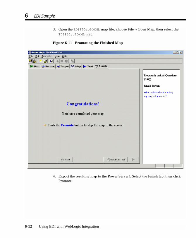
6 EDI Sample
6-12 Using EDI with WebLogic Integration
3. Open the EDI850toPOXML map file: choose File→Open Map, then select theEDI850toPOXML map.
Figure 6-11 Promoting the Finished Map
4. Export the resulting map to the Power.Server!. Select the Finish tab, then clickPromote.
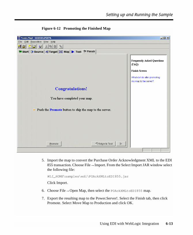
Setting up and Running the Sample
Using EDI with WebLogic Integration 6-13
Figure 6-12 Promoting the Finished Map
5. Import the map to convert the Purchase Order Acknowledgment XML to the EDI855 transaction. Choose File→Import. From the Select Import JAR window selectthe following file:
WLI_HOME\samples\edi\POAckXMLtoEDI855.jar
Click Import.
6. Choose File→Open Map, then select the POAckXMLtoEDI855 map.
7. Export the resulting map to the Power.Server!. Select the Finish tab, then clickPromote. Select Move Map to Production and click OK.

6 EDI Sample
6-14 Using EDI with WebLogic Integration
8. Import the XML envelope. Choose File→Import. Import the following file:
WLI_HOME\samples\edi\XMLEnvelope.jar
9. Choose File→Open Document Definition, then select XMLEnvelope and clickOK.
10. Export the result to the Power.Server!. Select the Finish tab, then click Promote.Select Move Doc to Production and click OK.
11. You are now finished with Power.Map. You can exit it at this time.
Step 4: Set Up the Connections
1. From within Power.Manager!, click Connections.
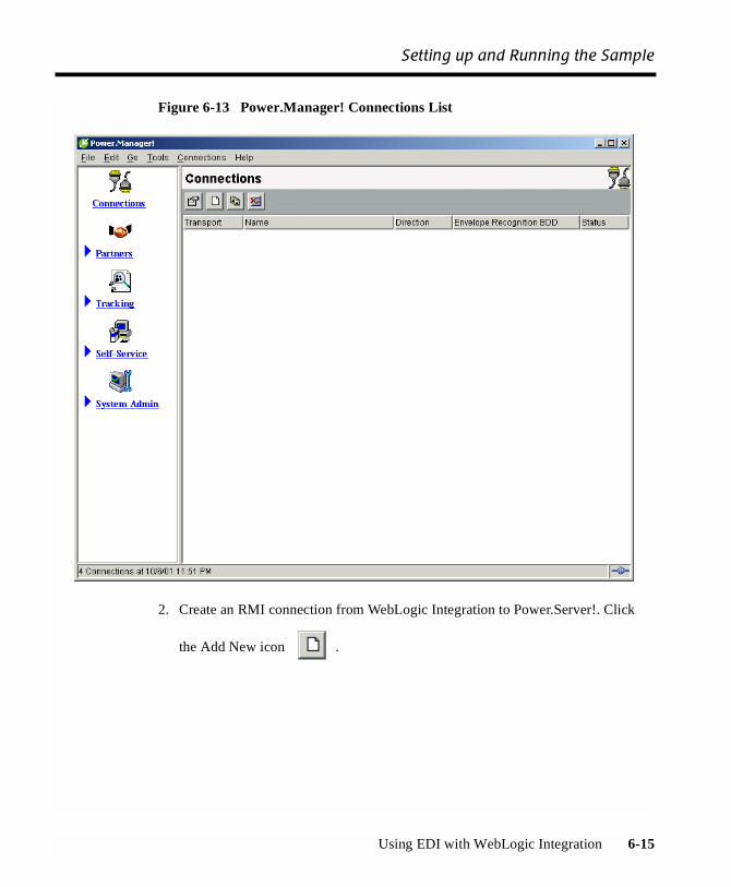
Setting up and Running the Sample
Using EDI with WebLogic Integration 6-15
Figure 6-13 Power.Manager! Connections List
2. Create an RMI connection from WebLogic Integration to Power.Server!. Click
the Add New icon .
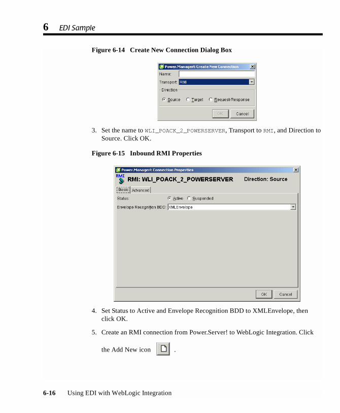
6 EDI Sample
6-16 Using EDI with WebLogic Integration
Figure 6-14 Create New Connection Dialog Box
3. Set the name to WLI_POACK_2_POWERSERVER, Transport to RMI, and Direction toSource. Click OK.
Figure 6-15 Inbound RMI Properties
4. Set Status to Active and Envelope Recognition BDD to XMLEnvelope, thenclick OK.
5. Create an RMI connection from Power.Server! to WebLogic Integration. Click
the Add New icon .

Setting up and Running the Sample
Using EDI with WebLogic Integration 6-17
6. Set the name to POWERSERVER_2_WLI_PO, Transport to RMI, and Direction toTarget. Click OK.
Figure 6-16 Outbound RMI Properties
7. Set Status to Active, Target to localhost, and Service Name to PO, then clickOK.
8. Create an inbound file connection. Click the Add New icon .
9. Set the name to EDIFILE_2_POWERSERVER, Transport to File, and Direction toSource. Click OK.

6 EDI Sample
6-18 Using EDI with WebLogic Integration
Figure 6-17 Inbound File Properties
Set the following properties:
� Status: Active
� Envelope Recognition BDD: X12
� Directory Path: <WLI_HOME>\samples\edi
� Filename: EDIPurchaseOrder.txt
� Do not set any other options.
Click OK when you are finished.
10. Create an outbound file connection. Click the Add New icon .
11. Set the name to POWERSERVER_2_EDIFILE, Transport to File, and Direction toTarget. Click OK.
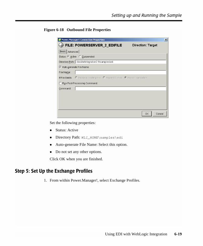
Setting up and Running the Sample
Using EDI with WebLogic Integration 6-19
Figure 6-18 Outbound File Properties
Set the following properties:
� Status: Active
� Directory Path: WLI_HOME\samples\edi
� Auto-generate File Name: Select this option.
� Do not set any other options.
Click OK when you are finished.
Step 5: Set Up the Exchange Profiles
1. From within Power.Manager!, select Exchange Profiles.

6 EDI Sample
6-20 Using EDI with WebLogic Integration
Figure 6-19 Power.Manager! Exchange Profiles List
2. Set up the inbound EDI exchange profile. Click the Add New icon. ThePower.Manager! Exchange Profile Properties window is displayed.

Setting up and Running the Sample
Using EDI with WebLogic Integration 6-21
Figure 6-20 New Exchange Profile Dialog Box
3. Set the following properties:
� Map Name: EDI850toPOXML
� Source Connection: EDIFILE_2_POWERSERVER
� Target Connection: POWERSERVER_2_WLI_PO
� Profile Status: Active
� Partner Company: AES
� Role: Sender
� Identifier: ISASNDR99

6 EDI Sample
6-22 Using EDI with WebLogic Integration
� On Compliance Error: Reject Document
� Do not set any other options.
Click OK when you are finished.
4. Set up the outbound EDI exchange profile. Click the Add New icon .
5. Set the following properties:
� Map Name: POAckXMLtoEDI855
� Source Connection: WLI_POACK_2_POWERSERVER
� Target Connection: POWERSERVER_2_EDIFILE
� Profile Status: Active
� Partner Company: AES
� Role: Receiver
� Identifier: ISASNDR99
� On Compliance Error: Reject Document
� Do not set any other options.
Click OK when you are finished.
Step 6: Set Up the Workflow
Note: If you have executed the Run Samples setup, as discussed in “Preparing to Runthe Samples” in “Getting Started,” in Running the B2B Integration Samples,you can skip Step 6: Set Up the Workflow and Step 7: Deploy the ApplicationView and proceed to Step 8: Run the Sample.
1. Start WebLogic Server: choose Start→Programs→BEA WebLogic E-BusinessPlatform→WebLogic Integration 2.1→Samples→Start Server.
2. Start the WebLogic Integration Studio: choose Start→Programs→BEA WebLogicE-Business Platform→WebLogic Integration 2.1→Start Studio.
3. Log on to WebLogic Integration Studio. The default login for the Samples is:
� User ID: joe

Setting up and Running the Sample
Using EDI with WebLogic Integration 6-23
� Password: password
4. Choose Tools→Import Package.
5. Select the file EDISampleWorkflow.jar, located in WLI_HOME\samples\edi.
Figure 6-21 Importing the EDI Workflow
6. Select Activate Workflows After Import. If prompted, use Org1.
Step 7: Deploy the Application View
1. Start a Web browser.
2. Connect to http://localhost:7001/wlai.
3. Log in using the system login ID:
� ID: system
� Password: security

6 EDI Sample
6-24 Using EDI with WebLogic Integration
Alternately, create a new user using the application integration functionalityprovided by WebLogic Integration. Then log in as that user.
4. Select the Application View EDIAppView.
5. Click Deploy. Select the Deploy Persistently option.
6. Click Deploy on the Deploy Application View page. You should see the statuschange.
This concludes the configuration of the EDI sample.
Step 8: Run the Sample
There are two ways to launch the sample:
1. You can run a script, which is located in the Power.Commerce! installation. In acommand prompt window, run the following command line:
power_enterprise_dir\powerit\powerapi\file_request -cEDIFILE_2_POWERSERVER
2. You can start the sample from the Samples Launch page, as discussed in Runningthe B2B Integration Samples.
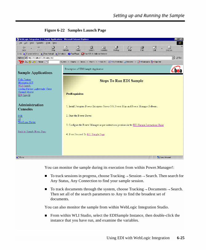
Setting up and Running the Sample
Using EDI with WebLogic Integration 6-25
Figure 6-22 Samples Launch Page
You can monitor the sample during its execution from within Power.Manager!:
� To track sessions in progress, choose Tracking→Session→Search. Then search forAny Status, Any Connection to find your sample session.
� To track documents through the system, choose Tracking→Documents→Search.Then set all of the search parameters to Any to find the broadest set ofdocuments.
You can also monitor the sample from within WebLogic Integration Studio.
� From within WLI Studio, select the EDISample Instance, then double-click theinstance that you have run, and examine the variables.

6 EDI Sample
6-26 Using EDI with WebLogic Integration
To verify that the sample has run correctly, go to WLI_HOME\samples\edi. Youshould see a new file in the directoy, which is auto-created by Power.Server! when theEDI message completes the cycle.
Using EDI with WebLogic Integration 7-1
CHAPTER
7 Power.Enterprise! Tuning Guide
This section discusses tuning issues for Power.Enterprise! and Power.Server!. Thefollowing topics are discussed:
� Tuning the Java Virtual Machine
� Tuning the Database
� Tuning Power.Server!
� HTTP and HTTPS Server Configuration
Tuning the Java Virtual Machine
This section discusses the tuning options used with the Java Virtual Machine, which isused to run all of the Power.Enterprise! software. Tuning of JVM arguments forWindows and UNIX systems is discussed, as well as memory usage and theassignment of port numbers for Power.Server! access.
Specifying JVM Arguments under Windows
The file applaunch.properties, located in power_enterprise_install\bin,
contains a separate section for each application: Power.Map!, Power.Manager!,Power.Server!, DBWizard.

7 Power.Enterprise! Tuning Guide
7-2 Using EDI with WebLogic Integration
For example:
[PowerMap]
install_dir="D:\Program Files\PowerE-3.0GA"jvm_args="-Duser.dir=. -Dsun.java2d.noddraw-Dvalidationlist.dir=.\data\codes"
jre_dir=.\jre
classpath=;.\lib\regional.jar;.\lib\activation.jar;.\lib\mail.jar;.\lib\PowerMapper\ecm.jar;.\lib\PowerMapper\hlvm.jar;.\lib\hlmetadata.jar;.\lib\xml4j.jar;.\lib\standards.jar;.\lib\mek.jar;.\jre\lib\ext\jhall.jar;.\lib\fesi.jar;.\lib\fldapi.jar;.\lib\fldshared.jar;.\lib\hlcommon.jar;.\lib\fldcommon.jar;.\lib\mekshared.jar;.\lib\fldrmi.jar;.\lib\fldserver.jar;.\lib\PowerManager\ecm.jar;.\bin\resources;.\bin\resources\msgd;.\lib\pipeline.zip;.\lib\edi.jar
connectors=.\connectors
database=.\database
standards=.\standards
imports=.\standards\import
To change the JVM arguments, or supply new ones, simply change the jvm_args line.
Note: Do not change any of the other values, as this will adversely affect the workingof the application.
Specifying JVM Arguments under UNIX
On a UNIX platform, JVM arguments are simply edited directly in the script that callsthe Java application. These are located in the directoriespower_enterprise_install/bin and power_enterprise_install/powerapi
For example, server_start.sh, located in power_enterprise_install/bin,contains the following:
. /home/fld/PE3.0VERYFINALGA/bin/power_env.sh
java -Xmx512m -Xms256m -Dfld.rmiregistry=true-Djava.security.policy=$INSTALLDIR/bin/resources/fld.policy

Tuning the Java Virtual Machine
Using EDI with WebLogic Integration 7-3
-Dvalidationlist.dir=./data/codes -Dfld.trace=false-user.dir=$INSTALLDIR com.harbinger.fld.jtd.container.HLFLDServer
JVM Memory Usage
The minimum and maximum amounts of memory available to the JVM are specifiedusing the standard -Xms and -Xmx JVM arguments, respectively. If out-of-memoryerrors are generated when you are transforming large documents, increase themaximum memory size and restart the server. By default, the server is configured fora minimum of 256MB and a maximum of 512MB of memory.
Server Port Numbers
Four port numbers are used by the server for client communication and transformationrequests.
Two of these numbers, configured through the System Administration section ofPower.Manager!, are related to the port on which the RMI registry is running. Ifnecessary, two RMI registries can be used for client communication andtransformation requests. By default, however, only one registry, on port 1099, is used.
The two remaining numbers represent the actual ports on which the server listens forthese requests. By default, these port numbers are 2500 and 2501. They may bechanged only by adding two JVM arguments to the script: powere.rmi.dcport andpowere.rmi.apiport, representing daemon control and a transformation APIrequest, respectively. Add these arguments as follows:
. /home/fld/PE3.0VERYFINALGA/bin/power_env.sh
java -Xmx512m -Xms256m -Dpowere.rmi.dcport=2597-Dpowere.rmi.apiport=2598 -Dfld.rmiregistry=true-Djava.security.policy=$INSTALLDIR/bin/resources/fld.policy-Dvalidationlist.dir=./data/codes -Dfld.trace=false-user.dir=$INSTALLDIR com.harbinger.fld.jtd.container.HLFLDServer
or
[PowerServer]install_dir="D:\Program Files\PowerE-3.0GA-Server"jvm_args="-Xmx512m -Xms256m -Dpowere.rmi.dcport=2597-Dpowere.rmi.apiport=2598-Djava.security.policy=.\bin\resources\fld.policy-Dfld.trace=false -Duser.dir=. -Dpowere.rmi.internalregistry=true-Dvalidationlist.dir=.\data\codes"jre_dir=.\jre
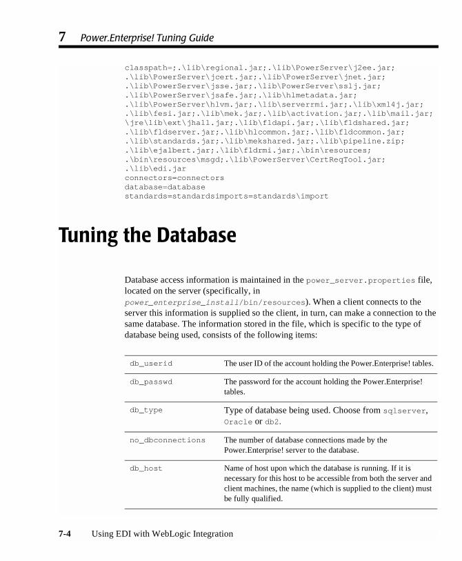
7 Power.Enterprise! Tuning Guide
7-4 Using EDI with WebLogic Integration
classpath=;.\lib\regional.jar;.\lib\PowerServer\j2ee.jar;.\lib\PowerServer\jcert.jar;.\lib\PowerServer\jnet.jar;.\lib\PowerServer\jsse.jar;.\lib\PowerServer\sslj.jar;.\lib\PowerServer\jsafe.jar;.\lib\hlmetadata.jar;.\lib\PowerServer\hlvm.jar;.\lib\serverrmi.jar;.\lib\xml4j.jar;.\lib\fesi.jar;.\lib\mek.jar;.\lib\activation.jar;.\lib\mail.jar;\jre\lib\ext\jhall.jar;.\lib\fldapi.jar;.\lib\fldshared.jar;.\lib\fldserver.jar;.\lib\hlcommon.jar;.\lib\fldcommon.jar;.\lib\standards.jar;.\lib\mekshared.jar;.\lib\pipeline.zip;.\lib\ejalbert.jar;.\lib\fldrmi.jar;.\bin\resources;.\bin\resources\msgd;.\lib\PowerServer\CertReqTool.jar;.\lib\edi.jarconnectors=connectorsdatabase=databasestandards=standardsimports=standards\import
Tuning the Database
Database access information is maintained in the power_server.properties file,located on the server (specifically, inpower_enterprise_install/bin/resources). When a client connects to theserver this information is supplied so the client, in turn, can make a connection to thesame database. The information stored in the file, which is specific to the type ofdatabase being used, consists of the following items:
db_userid The user ID of the account holding the Power.Enterprise! tables.
db_passwd The password for the account holding the Power.Enterprise!tables.
db_type Type of database being used. Choose from sqlserver,Oracle or db2.
no_dbconnections The number of database connections made by thePower.Enterprise! server to the database.
db_host Name of host upon which the database is running. If it isnecessary for this host to be accessible from both the server andclient machines, the name (which is supplied to the client) mustbe fully qualified.

Tuning the Database
Using EDI with WebLogic Integration 7-5
The following three sections provide examples files for the following types ofdatabases: Microsoft SQL Server, Oracle, and IBM DB2.
SQL Server
#FLD Server Properties#Thu Aug 30 12:03:49 GMT+01:00 2001db_userid=fld2db_passwd=fld2db_type=sqlserverno_dbconnections=5db_host=greedo.man.harbinger.co.ukdb_server=fld2db_dbname=fld2db_port=1433
Oracle
#FLD Server Properties#Tue Sep 18 16:00:18 BST 2001db_userid=fld8db_passwd=fld8db_type=Oracleno_dbconnections=5db_host=mace.man.harbinger.co.ukdb_server=fldWE8ISOdb_port=1521
db_server For SQL Server and DB2, the name of the databasecontaining the Power.Enterprise! tables. For Oracle, thename of the Oracle instance containing thePower.Enterprise! tables.
db_dbname For SQL server and DB2, the name of the databasecontaining the Power.Enterprise! tables. For Oracle, thename of the Oracle instance containing thePower.Enterprise! tables.
db_port The TCP/IP port for the database containing thePower.Enterprise! tables.
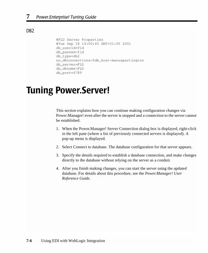
7 Power.Enterprise! Tuning Guide
7-6 Using EDI with WebLogic Integration
DB2
#FLD Server Properties#Tue Sep 18 14:00:45 GMT+01:00 2001db_userid=flddb_passwd=flddb_type=db2no_dbconnections=5db_host=manuapartingtondb_server=FLDdb_dbname=FLDdb_port=6789
Tuning Power.Server!
This section explains how you can continue making configuration changes viaPower.Manager! even after the server is stopped and a connection to the server cannotbe established.
1. When the Power.Manager! Server Connection dialog box is displayed, right-clickin the left pane (where a list of previously connected servers is displayed). Apop-up menu is displayed.
2. Select Connect to database. The database configuration for that server appears.
3. Specify the details required to establish a database connection, and make changesdirectly to the database without relying on the server as a conduit.
4. After you finish making changes, you can start the server using the updateddatabase. For details about this procedure, see the Power.Manager! UserReference Guide.

HTTP and HTTPS Server Configuration
Using EDI with WebLogic Integration 7-7
HTTP and HTTPS Server Configuration
You can configure the HTTP and HTTP servers at a low level through thesocket.properties file. This file resides inpower_enterprise_install/bin/resources on the server installation. Eachparameter is documented within the file.

7 Power.Enterprise! Tuning Guide
7-8 Using EDI with WebLogic Integration