Embed Size (px)
Citation preview
Be Smarter and TougherWelding will Advance to the Next Stage
WB-P500LWB-P500L WB-P400WB-P400
WB-M350LWB-M350L WB-M350WB-M350WB-M500WB-M500
•Optional accessories
* In the case of using the extension cable,the standard power cable(2m) is not necessary.* In the case that this welding machine is used for an automatic machine or is used with an electric current value close to current rating, use a cable whose size is larger by one rank.
Gas HoseWire Feeder Control Cable(10pins)Control cable for the analog remote control box(6cores)
Water Hose
WB-M350WB-M350LWB-P400WB-P500L
WB-M500
5mBKPDT-3807BKPDT-6007BKPDT-8007B K P T - 6 0 0 7
-BKGG-0605BKCPJ-1005BKCPJ-0605BKWR-0605
10mBKPDT-3812BKPDT-6012BKPDT-8012BKPT-6012
-BKGG-0610BKCPJ-1010BKCPJ-0610BKWR-0610
15mBKPDT-3817BKPDT-6017BKPDT-8017BKPT-6017BKPT-8017BKGG-0615BKCPJ-1015BKCPJ-0615BKWR-0615
20mBKPDT-3822BKPDT-6022BKPDT-8022BKPT-6022BKPT-8022BKGG-0620BKCPJ-1020BKCPJ-0620BKWR-0620
•Water-cooler
Water coolerHose
Product namePU-301
BBPU-3002
Product number
· Voltage detection cable
* K5791G00 is included with WB-M350L and WB-P500L
5mK5791G00
10mK5416N00
15m-
20mK5791E00Voltage detection cable
•Welding torch
AUnit form
%-
mm
m
Rated electric current
Cooling systemUsage rate
Suitable wire diameter
Cable length
Product name WTCW-5001
Water cooling3
500(1.2),1.4,1.6
70
•Wire feeder unit
mm-
m/minmmkg
Unit form CMW-742
207x602x37213
(1.2),1.4,(1.6)A solid wire and flux wire
22(Maximum)
Product name
Outside dimension(W×D×H)
Wire usedWire feeding speed
Mass
Suitable wire diameter
•Water-cooled kit
* When connect a water-cooled kit, please order your dealer by all means.
Water-cooled kitProduct number
K5848A00Product name
•Setting for water-cooled torch(WB-M500)
· Welding Torch
Product nameRated electric currentSuitable wire diameter
Usage rateCooling system
· Stainless MIG Welding Torch
Cable length
*1 WTS300-SD300
(0.9),(1.0),1.250
Air cooling3
*2 WTCSW-5002500
1.2,1.670
Water cooling3
*1 U5365P00 is necessary for WB-M350L and WB-P500L.*2 Compliant wire feeder is CMW-742.
AUnit form
mm%-m
Digital remote control box Product number
E-2454BKCAN-0405(5m)
BKCAN-0410(10m)K5810B00Converter cable
Control cable
Product name
· Digital Remote Controller (Following three parts are necessary.)
* Software update is necessary. Please contuct your dealer for details.
N E W
ISO 9001 Registered
Welbee Inverter
· Extension cables
Wire FeederPower cable /Base Metal
Power Cable
(38mm2)(60mm2)(80mm2)(60mm2)(80mm2)
· Interface and wire feeder for robot manufautured by another company
Interface boxWire feeder
Product numberIFR-101WBCMRE-741
Product name
* When connect to robot manufactured by another company, please contuct us for details.
* In the case of using a wire with the diameter indicated in the parenthesis, an optional part is necessary.
*Suitable wire diameterWire used
Wire feeding speed Outside dimension(WxDxH)
Mass
CMRE-741
195x275x248(Excluding cables)7
(0.8),0.9,1.0,1.2,(1.4),(1.6)A solid wire and flux wire
22
•Wire feedermm
-m/minmmkg
Unit form
bes m a r tt o u g h
Distributed by :
4-1,Koyocho-nishi,Higashinada-ku,Kobe,Hyogo 658-0033,JapanPhone:(Country Code 81)78-275-2006Fax: (Country Code 81)78-845-8159
In accordance with DAIHEN's policy to make continuing improvements,design and/or specifications aresubject to change without notice and without any obligation on the part of manufacturer.
Environmentally friendly items, such as "Vegetable oil ink" and "FSCTM certification paper," are used for creation of this catalogue.
· Remote control Box
Product numberK5416Z00Analog remote control box(3m)
Product name· Analog Remote Controller
1 2
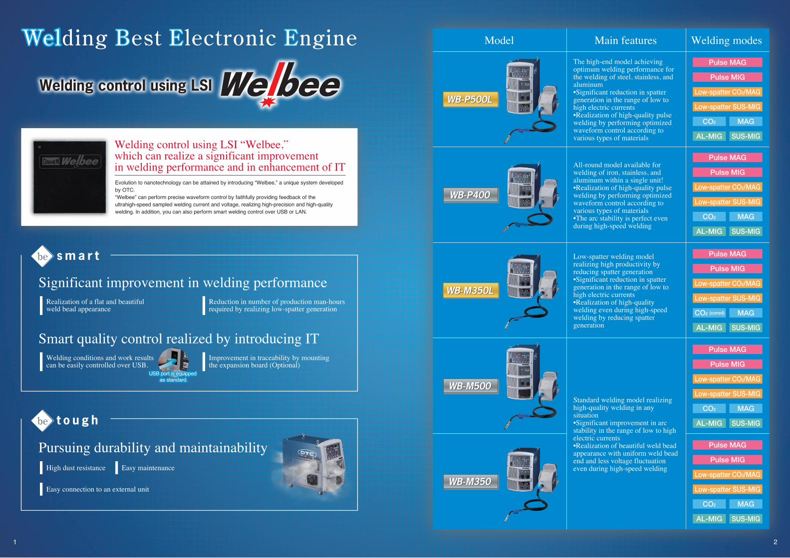
Welding control using LSI “Welbee,” which can realize a significant improvement in welding performance and in enhancement of ITEvolution to nanotechnology can be attained by introducing “Welbee,” a unique system developed by OTC.“Welbee” can perform precise waveform control by faithfully providing feedback of the ultrahigh-speed sampled welding current and voltage, realizing high-precision and high-quality welding. In addition, you can also perform smart welding control over USB or LAN.
Welding control using LSI
High dust resistance
Easy connection to an external unit
Easy maintenance
be t o u g h
be s m a r t
Reduction in number of production man-hours required by realizing low-spatter generation
Realization of a flat and beautiful weld bead appearance
Improvement in traceability by mounting the expansion board (Optional)
Welding conditions and work results can be easily controlled over USB.
Model Main features
The high-end model achieving optimum welding performance for the welding of steel, stainless, and aluminum •Significant reduction in spatter generation in the range of low to high electric currents•Realization of high-quality pulse welding by performing optimized waveform control according to various types of materials
Standard welding model realizing high-quality welding in any situation•Significant improvement in arc stability in the range of low to high electric currents•Realization of beautiful weld bead appearance with uniform weld bead end and less voltage fluctuation even during high-speed welding
Low-spatter welding model realizing high productivity by reducing spatter generation•Significant reduction in spatter generation in the range of low to high electric currents•Realization of high-quality welding even during high-speed welding by reducing spatter generation
All-round model available for welding of iron, stainless, and aluminum within a single unit!•Realization of high-quality pulse welding by performing optimized waveform control according to various types of materials•The arc stability is perfect even during high-speed welding
Welding modes
Pulse MAG
Pulse MIG
Low-spatter CO2/MAG
Low-spatter SUS-MIG
CO2 MAG
AL-MIG SUS-MIG
Pulse MAG
Pulse MIG
Low-spatter CO2/MAG
Low-spatter SUS-MIG
CO2 MAG
AL-MIG SUS-MIG
Pulse MAG
Pulse MIG
Low-spatter CO2/MAG
Low-spatter SUS-MIG
CO2 MAG
AL-MIG SUS-MIG
Pulse MAG
Pulse MIG
Low-spatter CO2/MAG
Low-spatter SUS-MIG
CO2 MAG
AL-MIG SUS-MIG
USB port is equipped as standard.
Significant improvement in welding performance
Smart quality control realized by introducing IT
Pursuing durability and maintainability
WB-P500LWB-P500L
WB-P400WB-P400
WB-M350LWB-M350L
WB-M350WB-M350
WB-M500WB-M500
Pulse MAG
Pulse MIG
Low-spatter CO2/MAG
Low-spatter SUS-MIG
CO2 MAG
AL-MIG SUS-MIG
(cored)

Welding Best Electronic Engine
3 4
In addi t ion, you can easi ly real ize a beaut i fu l bead appearance with modulation equivalent to that of TIG welding by controlling the arc length and the wire feeding speed using the wave pulse welding method.
·Welding electric current:120A·Welding voltage:16V·Sheet thickness:3.0mmt·Wire diameter:φ1.2mm·Welding speed:50cm/min·Wave frequency:2.5Hz
In combination with the ALMEGA PREMIUM Friendly series, you can optimize the performance of Welbee. You can perform high-speed pulse welding by setting an optimum waveform by interlocking with the speed information specified from the teaching pendant.
High-speed pulse mode (For ALMEGA)
You can obtain a good bead even during high-speed welding of a stainless steel sheet because the pulse waveform control, which is exclusive for stainless steels and is unique to OTC, can securely realize droplet transfer even for a highly viscous stainless steel wire.
Easy high-speed welding of thin stainless steel sheet
·Welding electric current:145A·Welding voltage:23V·Sheet thickness:2.0mmt·Wire diameter:φ1.2mm·Welding speed:100cm/min
Offering highest welding performance for the welding of iron, stainless, and aluminum!
·Welding electric current:280A·Welding voltage:21V·Sheet thickness:1.5mmt·Wire diameter:φ1.2mm·Welding speed:160cm/min
You can significantly reduce the generation of dust-like spatter, which is problematic during aluminum welding, by employing OTC’s original and novel pulse waveform control in which the electric current is changed moderately.
Even if a strong upwash of zinc vapor occurs when welding galvanized sheet iron, the novel optimized intelligent filter will enable you to perform stable welding. In addition, you can easily realize an even bead with a uniform end.
Beautiful bead appearance using the aluminum MIG pulse waveform
[High-speed mode]
5mm
[Standard mode]
5mm
Even for galvanized sheet iron, in which blow holes are likely to be formed, you can reduce the number of blow holes by shaking a molten weld pool using the wave pulse welding method.
Improving the welding quality of galvanized sheet iron
·Welding electric current:300A ·Welding voltage:22V ·Sheet thickness:3.2mmt ·Wire diameter:φ1.2mm ·Welding speed:150cm/min ·Wire feeding speed:11.0m/min ·Protrusion:15mm
·Welding electric current:200A ·Welding voltage:25V·Thickness of galvanized sheet iron:9mmt·Wire diameter:φ1.2mm·Welding speed:30cm/min·Wave frequency:3Hz
Bead appearance views Macro section views
Cases w
ithout
wave p
ulse C
ases with
wave p
ulse
OTC’s pulse waveform control to realize high-quality welding
MAG pulse waveform for soft steels (WB-P500L)MIG pulse waveform for stainless steelsMIG pulse waveform for aluminum
The Welbee inverter series affords the following advantages for performing optimum waveform control depending on the type of welding material.
You can realize an arc with less spatter generation in the range of low to high electric currents.You can realize good welding for sur face- t reated steel mater ia ls including galvanized sheet iron.You can increase the amount of melted wire and easily achieve a desired bead width even during high-speed welding.
·
·
·
10mm 10mm
Conventional welding machine Welbee
Pulse welding is a technique in which high (peak) electric current and low (base) electric current are applied at intervals to break away a droplet formed at the tip of a wire using the electromagnetic pinch force generated by the pulse electric current.
What is pulse welding? Peak electric current
Base electric current
·Welding electric current:230A ·Welding voltage:23.5V ·Shield gas:80%Ar+20%CO2·Welding base material:Galvanized sheet iron:45g/m2,2.3mm ·Welding speed:100cm/min·Wire diameter:φ1.2mm ·Welded joint:Overlapped fillet welding
WB-P500LWB-P500L
WB-P400WB-P400

0.5mm or moreSpatters that require
a chisel for their removalafter they have adhered
Less than 0.2mmSpatters that
do not adhere
Spatter particle sizeInfluence on a base
material or a jig
5 6
Welding Best Electronic Engine
A molten pool becomes moderate via short circuit in a fixed cycle, realizing a flat weld bead with a uniform weld bead end.
Significant reduction of spatter generation not only in a low electric current range but also in mid and high electric current ranges
Realization of a further increase inspeed owing to expansion of the conditional tolerance
Realization of a flat and beautifulweld bead appearance
The tolerance of the lower limit voltage is expanded and spattergeneration is reduced even during high-speed welding,realizing high-quality welding.
150A 200A 250A100A
·Welding electric current:200A ·Welding speed:50cm/min ·Wire size:φ1.2mm·Shield gas:CO2 ·Welding time:2.5min
·Welding electric current:135A·Welding voltage:18V·Shield gas:CO2
·Plate thickness:1.6mmt·Wire size:φ1.2mm·Welding speed:70cm/min
Flat weld bead
100A 150A 200A 250A
Spatter quantity
Weldingelectric current
Weldingelectric current
Conventional machines Welbee Conventional machines Welbee
Reducing spatters to the utmost limiteven by MAG welding
Realization of low-spatter generation equivalent to MAG welding even using CO2 welding
Reduction of number of production man-hours required
Conventionalmachines
Welbee
Conventionalmachines
Welbee
Furthermore, the adhesion of generated spatters to a base material or a jig can be reduced owing to the small particle forms.As a result, you can significantly reduce the number of man-hours required for removing spatters, leading to a reduction in the frequency of cleanup work of the nozzle.
Conventionalmachines
Welbee
Conventionalmachines Welbee
·Welding electric current:220A ·Welding speed:100cm/min ·Shield gas:CO2
·Wire size:φ1.2mm ·Plate thickness:1.6mmt ·Gap:1.6mm
Spatter quantity
Reduction
CO2 MAG
Less than 0.2mm 0.2mm~0.5mm 0.5mm or more
Steep reduction of large spatters
This is a condition in which the weldbead cannot followbecause the voltagedoes not decrease.
Realization of a flat weld bead appearance with excellentheat input and deep molten status
Reduction in frequency of undercut occurrence andhumping during high-speed welding
You can easily widen the weld bead widthand expand the target tolerance shift.
Significant reduction of PAN start andprevention of weld bead chips at a start section
Improving the productivity by significantly reducing spatter generation!
Standard welding model realizing high-qualitywelding in every situation
Welding Best Electronic Engine
Welbee
A further increase in speed isrealized by mounting a high-speedwelding mode
·Welding electric current:250A ·Welding voltage:25V ·Welding speed:100cm/min·Wire size:φ1.2mm
A beautiful weld bead appearance and less voltage fluctuations are realized even during high-speed welding in which a minute fluctuation of the arc is likely to cause a defect in the weld bead appearance.
The startup performance isimproved by an evolveddigital start.The startup performance in the stainless mode is significantly improved by the digital turbo start and the end pulse function unique to OTC, which can optimize the wire tip shape.
A stable arc is realized even for a change in the protruding length or in weaving welding for a single-V groove joint.
·Welding electric current:300A·Welding voltage:30V·Wire size:φ1.2mm,Mild steel flux cored·Plate thickness:9mmt·Weaving frequency:2.5Hz Oscillation:±1.5mm
·Welding electric current:130A·Welding voltage:16.5V·Shield gas:MAG·Plate thickness:1.6mmt
Uniform and beautiful weld bead appearancewith a small amount of spatter
Realization of a flat weld bead appearancewith fewer uneven sections on the surface
Flat weld bead
Material:Stainless
Optimization of the wire tip shapeby the end pulse function!
(Removal of insulating materials)
Conventionalmachines
PAN start
Significant improvement in the arc stability in the rangefrom low to high electric currentsHigh-performance welding for a wide range from semi-automatic to automatic machines can be realized by performing optimal and finewaveform control according to carefully divided applications (standard/high speed/extension).
by up to
at 200A80%
Reductionby up to
at 200A60%
0.2~0.5mmSpatters that can be
removed easily even when they adhere
WB-P500LWB-P500L
WB-M350LWB-M350L WB-M350WB-M350
WB-M500WB-M500

Welding Best Electronic Engine
7 8
Adjusting the welding electric current by clicking
Smart functions to improve the productivity
You can increase or decrease the output electric current by any preset amount of change by operating the torch switch (single click/double click). If you want to change the input heat during welding in accordance with sheet-thickness changes, you can change the welding conditions without suspending your welding work.
High-speed tack startYou can use settings such that the welding machine starts skipping the slowdown feeding operation when the torch switch is pressed again within 0.5s after completing the welding work.You can realize satisfactory tack welding, resulting in a reduction in the number of working hours.
Abundant welding modes
CO2
CO2
CO2
CO2
CO2
CO2
CO2
Direct current
Direct current
Direct current
Direct current
Direct current
Direct currentlow spatter
Direct current pulse
Direct current pulse
Direct currentlow spatter
Direct currentwave pulse
Direct currentwave pulse
Model
WB-M350
WB-M500
WB-M350L
WB-P400
WB-P500L
Welding process Gas Wire Wire size (mmφ)
0.8 0.9 1.0 1.2 -
---
-----
--
---
1.2 1.40.9 1.2
0.8 0.9 1.0 1.20.8 0.9 1.0 1.2
1.2 1.4 1.61.2 1.4 1.61.2 1.61.2 1.4 1.61.2 1.61.2 1.4
0.9 1.20.8 0.9 1.0 1.20.8 0.9 1.0 1.20.8 0.9 1.0 1.20.8 0.9 1.0 1.2
1.0 1.20.9 1.2
0.8 0.9 1.0 1.20.8 0.9 1.0 1.2
1.0 1.2 1.61.2 1.6
0.9 1.0 1.20.9 1.0 1.2
1.0 1.2 1.61.2 1.6
0.9 1.0 1.20.9 1.0 1.2
1.0 1.2 1.61.2 1.6
0.8 0.9 1.0 1.2 1.4 1.61.0 1.2 1.4 1.6
0.9 1.2 1.60.8 0.9 1.0 1.2 1.4 1.60.8 0.9 1.0 1.2 - 1.60.8 0.9 1.0 1.2
1.0 1.2 1.61.2 1.6
0.8 0.9 1.0 1.20.8 0.9 1.0 1.20.8 0.9 1.0 1.20.8 0.9 1.0 1.20.8 0.9 1.0 1.2 1.4 1.6
0.9 1.0 1.20.8 0.9 1.0 1.2
1.0 1.2 1.61.2 1.6
0.9 1.0 1.20.9 1.0 1.20.9 1.0 1.2
1.0 1.2 1.61.2 1.6
100A 100A 100A90A90A
80A
110A
60A
Final welding Crater
Torch switch
Torch switch
Output electric voltage
Weldingelectric current
Wirefeeding speed
Welding electric current
ON
0.3s
OFF
Doubleclick
Singleclick
[Example] < Conditions >·Crater setting:Existence
·Initial conditions:Non-existence
·Welding electric current:100A
·Function No.[48] (Electric current adjustment by operating the torch switch):ON
·Function No.[49] (Amount of electric-current increase and decrease by single click):-10
·Function No.[50] (Amount of electric-current increase and decrease by double click):20
·Crater electric current:60A
·Function No.[54]:ON
Finalwelding
Finalwelding
Finalwelding
ON
Pre-flow time
Anti-stick time
After-flow time
ONON
OFF OFF
Non-loadvoltage
Within 0.5s Within 0.5s
*You cannot use this function when the analog remote controller is connected.
*Welding modes may be changed for your area.
Welding Best Electronic Engine
MAG[80%Ar+20%CO2]
MAG[80%Ar+20%CO2]
MAG[80%Ar+20%CO2]
MAG[80%Ar+20%CO2]
MAG[80%Ar+20%CO2]
MIG[98%Ar+2%O2]
MIG[98%Ar+2%O2]
MIG[98%Ar+2%O2]
MIG[98%Ar+2%O2]
MAG[80%Ar+20%CO2]
MAG[80%Ar+20%CO2]
MAG[80%Ar+20%CO2]
MAG[80%Ar+20%CO2]
MIG[98%Ar+2%O2]
MIG[98%Ar+2%O2]
MIG[98%Ar+2%O2]
MIG[98%Ar+2%O2]
MIG[98%Ar+2%O2]
MIG[Ar]
MIG[Ar]
MAG[80%Ar+20%CO2]MIG[98%Ar+2%O2]
MIG[Ar]
MIG[Ar]
MIG[Ar]
MIG[Ar]
Soft steel solid
Soft steel solidStainless steel solid
Soft steel flux coredStainless flux cored
Soft steel solid
Soft steel solid
Soft steel solid
Soft steel solid
Soft steel solid
Soft steel solid
Soft steel solidSoft steel solid
Soft steel solid
Soft steel solid
Soft steel solid
Soft steel solid
Soft steel solid
Soft steel solidStainless steel solid
Stainless steel solid
Stainless steel solid
Stainless steel solid
Stainless steel solid
Stainless steel solid
Stainless steel solid
Stainless steel solid
Stainless steel solid
Hard aluminumSoft aluminum
Hard aluminumSoft aluminum
Hard aluminumSoft aluminum
Hard aluminumSoft aluminum
Hard aluminumSoft aluminum
Hard aluminumSoft aluminum
Soft steel flux cored
Soft steel flux cored
Soft steel flux cored
Soft steel flux cored
Stainless flux cored
Stainless flux cored
Stainless steel flux cored
Stainless steel flux cored
Ferrite-system stainless steel solid
Ferrite-system stainless steel solid
Ferrite-system stainless steel solid
Ferrite-system stainless steel solid
- - -- - -- - -- - -- - -
-
---
- -- -
--
- -- -- -
--
-
-
----
-
- -
-
-
--
- -
-
- -- -- ----
-
- ----
- - -- - -
-
- -- - -
- -
-- -
-
-
---
-
- -- -- -- -
- 1.6---
-
-
- --
0.8
1.4 1.60.8- 1.60.8- -0.8
- -- -
-- -
-
-- - -
-
Slowdownfeeding

9 10
Welding condition edit Welding condition copy
Welding condition backup
Welding electric current (Setup) Welding voltage (Measured value)Welding voltage (Setup) Welding electric current (Measured value)
Motor electric currentFeeding speed Startup signals Input voltage at the primary side
Inching signals Power supply internal temperature FAN revolution
In addition, you can collect large amounts of detailed data over USB or LAN by mounting the expansion board. Accordingly, you can verify detailed information about what happened and when, and then utilize this for improving quality control through traceability as well as for troubleshooting.
You can easily edit the “Welding condition memory function” or its backup data using your PC because the USB port is equipped as standard.
PC edit screen
Welding monitor
Hardware requirements·For Windows 7/Vista:Pentium 4, 1 GHz or more/RAM, 1 GB or more/Screen resolution,1024×768 or larger ·For Windows XP, 2000:Pentium M, 1 GHz or more/RAM, 512 MB or more/Screen resolution:1024×768 or larger*A LAN connector (fixed cable) is necessary.
*Refer to the attached standard specifications for details.
Welding monitor (Optional)
Precisionpart area
Welbee side flow structure
Quality control by introducing IT and its expansibility Durability/maintainabilityand easy connection operation
Improvement in reliability is realized by adopting a separation structure that prevents dust from entering into the area in which electronic components etc. are mounted.
By controlling the revolutions of the cooling fan according to its usage rate or ambient air temperature, this welding machine can prevent dust from entering to the maximum extent possible. In addition, you can easily clean up dirt and dust by air-blowing them without opening the case.
*You can download it from OTS’s website free of charge. (http://www.daihen.co.jp/yosetsu/other/download.html)
Manufacturing products based on future perspectives
Using OTC’s unique inverter technology, you can reduce the energy loss by~10% if compared with conventional machines. (Rated power consumption of 15kW 13.6kW)
Energyconsumption
From the viewpoint of protecting the environment, this welding machine is compatible with Europe’s RoHS directive that regulates limitations on the use of environmentally hazardous substances.
Lead
This welding machine can reduce the amount of spatter generated in the mid and high electric current ranges by up to 80% if compared with conventional digital inverter welding machines. You can also reduce the amount of industrial waste and therefore contribute to environmental protection.
80% reduction
Welding Best Electronic Engine
You can connect this welding machine with externalequipment only by opening a small window on itsrear surface.
Easy connection to external equipment
•You can also monitor the wire feeding speed.
• The required monitoring items are arranged in an easy-to-see way by mounting the customization function.
Displayed example of the arc monitor screen
The machine’s capability is maximized by making a connection to the ALMEGA Friendly series.
Easy connection to external equipment using the connection terminal box that requires no tools
• Parameters in which data can be saved
Reduction ofspatter generation
by up to 80%Reduction of energy
loss by ~10%Compatible with
DOWN
RoHSstandards
• High dust resistance
• Easy maintenance
Dust penetration into theprecision parts is reduced
~98%!!by
•You can easily make a connection to the ALMEGA Friendly series because an interface board is equipped as standard.
•You can easily set up conditions on theWelbee special screen. •You can easily confirm the welding status on the arc monitor screen.
External I/O terminal box that requires no toolswhen carrying out connection works
WB-M350LWB-M350L
WB-P500LWB-P500L
WB-M350WB-M350
Individual screen
Collective control screen
Models for aluminum
11 12
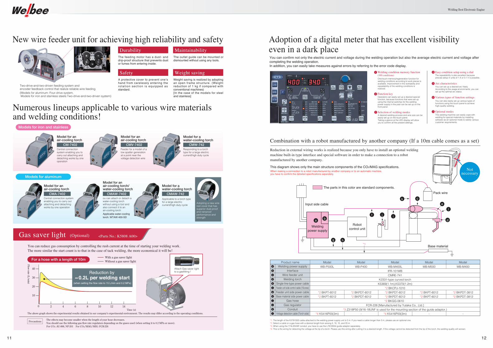
Combination with a robot manufactured by another company (If a 10m cable comes as a set)
This diagram shows only the main structure components of the CO2/MAG specifications.
Reduction in external wiring works is realized because you only have to install an optional welding machine built-in type interface and special software in order to make a connection to a robot manufactured by another company.
Notnecessary
a b
g h
f j i
k ce
l
d
Input side cable
Pack wire
Base material
Robotcontrol unit
*1
*1. The length of the K5791G00 cable attached to the welding power supply unit is 5 m. If you need a cable longer than 5 m, please use an optional one.*2. Select a cable or a gas hose with a desired length from among 5, 10, 15, and 20 m. *3. When using the 7/16-20UNF conduit, you have to use the L7810D04 guide adaptor separately. *4. This is the wiring for detecting the voltage at the tip of a torch. Please use this wiring after cutting it to a desired length. If the voltage cannot be detected from the tip of the torch, the welding quality will worsen.
Adoption of a digital meter that has excellent visibilityeven in a dark placeYou can confirm not only the electric current and voltage during the welding operation but also the average electric current and voltage after completing the welding operation. In addition, you can easily take measures against errors by referring to the error code display.
One-touch memory/regeneration function for welding conditions according to work pieces is available. Improvement in the workability and repeatability of the welding conditions is realized.
1 Welding condition memory function (100 conditions)
Operators can easily set up a desired special function, because functions that were set up using the internal switches for the welding power supply in the past can be set up on the front panel.
2 Function key
A desired welding process and wire size can be easily set up on the touch panel. Taking a glance at the LED display will allow you to confirm all the present settings.
3 Selection of welding modes
The repeatability is also excellent because precise setup in units of 1 A or 0.1 V is possible.
4 Easy condition setup using a dial
You can set up a desired arc freely. According to the usage environments, you can set up the optimal arc status.
5 Arc characteristics
You can also easily set up various types of functions using the touch panel to achieve high-quality welding.
6 Various types of function settings
This welding machine can easily cope with welding for special materials by installing software as an optional mode to satisfy various customer requirements.
7 Optional modes
Welding Best Electronic Engine
Two-drive-and-two-driven feeding system andencoder feedback control that realize reliable wire feeding
New wire feeder unit for achieving high reliability and safetyDurability Maintainability
The feeding motor has a dust- and drip-proof structure that prevents dust or fumes from entering inside.
The outlet guide can be mounted or dismounted without using any tools.
Safety Weight savingA protective cover to prevent one’s hand from carelessly entering the ro ta t ion sec t ion is equ ipped as standard.
Weight saving is realized by adopting an open frame structure. (Weight reduction of 1 kg if compared with conventional machines)[In the case of the models for steel and stainless]
Numerous lineups applicable to various wire materialsand welding conditions!
Central connection system enabling you to carry out attaching and detaching works by one operation
CMA-7402
Model for anair-cooling torch
ou can attach or detach a water-cooling torch without using a tool and also connect it to an air-cooling torchApplicable water-cooling torch: WTAW 400-SD
CMAW-7402
Model for anair-cooling torch/water-cooling torch
Applicable to a torch type for a large electric current/high duty cycle
Adopting a new wire reel cover that has superior dust-proof and rainproof performance and strength
CMAW-742
Model for awater-cooling torch
Central connection system enabling you to carry out attaching and detaching works by one operation
CM-7402
Model for anair-cooling torch
Feeder for a model of a low spatter generation at a point near the voltage detection wire
CMV-7402
Model for anair-cooling torch
Responding to a torch type for a large electric current/high duty cycle
CMW-742
Model for a water-cooling torch
Models for iron and stainless
a
b
c
d
e
f
g
h
i
j
k
l
Product name
IFR-101WBCMRE-741
K2331-type curved torchK5369(1.1m),K5370(1.2m)
*2 BKCPJ-1010
*2 BKGG-0610 FCR-226 [Manufactured by Yutaka Co., Ltd.]
*3 Z318P50 (9/16-18UNF is used for the mounting section of the guide adaptor.)
ModelWB-P400
-
*2 BKPDT-6012*2 BKPDT-6012
ModelWB-P500L
*4 K5416P00(3m)
*2 BKPT-6012*2 BKPT-6012
ModelWB-M400L
*4 K5416P00(3m)
*2 BKPDT-6012*2 BKPDT-6012
ModelWB-M500
-
*2 BKPT-6012*2 BKPT-6012
ModelWB-M400
-
*2 BKPDT-3812*2 BKPDT-3812
The parts in this color are standard components.
Weldingpower supply
Gas saver light (Optional)
You can reduce gas consumption by controlling the rush current at the time of starting your welding work.The more similar the start count is to that in the case of tack welding, the more economical it will be!
The above graph shows the experimental results obtained in our company’s experimental environment. The results may differ according to the operating conditions.
With a gas saver lightWithout a gas saver light
0
40
30
20
10
2 4 6 8 10 12 14
Flow rate (L/m
in)
Time (s)
·The effects may become smaller when the length of your hose decreases.·You should use the following gas flow rate regulators depending on the gases used (when setting it to 0.2 MPa or more). For CO2: AU-888, NP-201 For CO2/MAG/MIG: FCR-226
Precautions
For a hose with a length of 10m
<Parts No.: K5808 A00>
Reduction by ~ 0.2L per welding start
(when setting the flow rate to 15 L/min and 0.2 MPa)
(Models for aluminum: Four-drive system, Models for iron and stainless steels:Two-drive-and-two-driven system)
When making a connection to a robot manufactured by another company or to an automatic machine,you have to confirm the detailed specifications separately.
Welding power supplyInterface
Wire feeder unitWelding torch
Single-line-type power cableFeeder unit side control cable (10cores)Feeder unit side power cableBase material side power cable
Gas hoseGas regulator
ConduitVoltage detection cable (Torch side)
Attach Gas saver light to a gasfitting !