Embed Size (px)
Citation preview

12 June 2007 BD Air Activated Exhaust Brake
1
BBDD AAIIRR AACCTTIIVVAATTEEDD EEXXHHAAUUSSTT BBRRAAKKEE
Motorhome/Truck 5.9/8.3L/L10 - Cat 3208T/3116 – IHC DT466/7.3L Ford Truck 6.6/7.8L - Ford 6.9/7.3L - Chev 6.2/6.5L - Dodge 5.9L
Serial # Date Purchased Purchased from
Installed by
***Please fill out and mail registration card as soon as possible. *** OWNER’S MANUAL – LEAVE IN GLOVE BOX
WARNING TO DRIVER The use of Exhaust Brakes for engine retarding below 1000 rpm could result in high exhaust temperatures, excess emissions, or engine stalling.

12 June 2007 BD Remote Mount Air Activated Exhaust Brake
BD Engine Brake Inc. Plant Address: Unit A10, 33733 King Rd, Abbotsford, BC, Canada V2S 7M9
U.S. Shipping Address: 88-446 Harrison St, Sumas, WA 98295 U.S. Mailing Address: P.O. Box 231, Sumas, WA 98295 Phone: 604-853-6096 Fax: 604-853-8749 Internet: www.bd-power.com
2
T A B L E O F C O N T E N T S
Kit Contents................................................................................................................3 Welcome ....................................................................................................................3 Pre-Installation ...........................................................................................................3 Valve Assembly Installation........................................................................................3 Control Box.................................................................................................................5 Throttle Switch............................................................................................................5
Cummins Motorhomes & Trucks.......................................................................5 Caterpillar Air Throttle .......................................................................................6 Generic .............................................................................................................6 Ford Pick-up (Non Powerstroke).......................................................................6 Dodge – 1994 to 1998 ......................................................................................9 Dodge – 1998½ to 2002 ...................................................................................9
For 6spd manual transmission only..............................................10 For all applications........................................................................11
Dodge - 1988 to 1993 .....................................................................................11 Chev/GMC 1994-Present................................................................................12
On all applications ........................................................................12 DFIV Calibration .......................................................................................................13 Power Switch & Optional Gauge ..............................................................................16 Optional Shifter Switch .............................................................................................17 Cruise Disable Function ...........................................................................................18
Chevy/GMC (1994-up) ....................................................................................18 Ford.................................................................................................................18
Exhaust Brake Testing .............................................................................................20 Maintenance.............................................................................................................20 Trouble Shooting......................................................................................................21 Cummins 5.9L Turbo Mount Exhaust Brake Addendum ..........................................23 Additional Wiring Instructions (Ford Powerstroke) ...................................................24 OPERATING GUIDELINES......................................................................................27 OPTIONS .................................................................................................................29 LIMITED WARRANTY STATEMENT.......................................................................30

12 June 2007 BD Remote Mount Air Activated Exhaust Brake
BD Engine Brake Inc. Plant Address: Unit A10, 33733 King Rd, Abbotsford, BC, Canada V2S 7M9
U.S. Shipping Address: 88-446 Harrison St, Sumas, WA 98295 U.S. Mailing Address: P.O. Box 231, Sumas, WA 98295 Phone: 604-853-6096 Fax: 604-853-8749 Internet: www.bd-power.com
3
Kit Contents
o Valve Assembly o Adapter Kit o Control Box Assembly o Application Kit
Welcome Thank you for purchasing a BD Engine Exhaust Brake. Your kit should have the above-mentioned items for your installation. Please check to make sure that you have everything. This manual is to aid your with your installation and operation of your braking unit. We strongly suggest that you fill out the information card and return it to the factory and retain this manual for future reference.
Please fill out and mail registration card as soon as possible. Pre-Installation Before installation can begin, we must take a look at any other requirements or options for your particular application. If the driver likes gauges, another handy option is the Brake Pressure Gauge Kit. This gauge will allow you to monitor the pressures being developed by the exhaust brake. Valve Assembly Installation In the engine compartment, locate the factory Vacuum Pump and if none is present (i.e. some 1988-93 Chevrolets), then the purchase of a BD Vacuum Pump kit (Part #1030120) is needed to supply the vehicle’s retarding needs. Inspect the vehicles exhaust system between the engine and the muffler. A straight section of pipe will have to be cut to accommodate the butterfly style valve of the Exhaust Valve Assembly, being approximately 7 to 8 inches. On 1994 or newer Dodges, the valve is mounted before the Catalytic Converter, on Ford and Chev/GM vehicles with Catalytic Converters, the valve is mounted between the Cat and muffler. There should be no exhaust-flex pipe between the engine and exhaust brake valve. However, if there is a flex pipe after the valve, then it is acceptable. Cut the exhaust pipe in a straight section of the system. You will need to weld one of the supplied adapters to the section of pipe coming from the front of the vehicle’s engine.

12 June 2007 BD Remote Mount Air Activated Exhaust Brake
BD Engine Brake Inc. Plant Address: Unit A10, 33733 King Rd, Abbotsford, BC, Canada V2S 7M9
U.S. Shipping Address: 88-446 Harrison St, Sumas, WA 98295 U.S. Mailing Address: P.O. Box 231, Sumas, WA 98295 Phone: 604-853-6096 Fax: 604-853-8749 Internet: www.bd-power.com
4
WeldHere
Use SSBand ClampUse V
Clamp
Rear of Truck
Temporarily mount the Exhaust Valve Assembly on the adapter, with the supplied V clamp on the valve sliding. From here, cut off as much of the remaining exhaust needed to accommodate the valve and remaining adapter. Remove the Exhaust Valve Assembly, and clamp or weld the rear adapter to the other section of exhaust pipe. Temporarily mount the Valve Assembly on the adapter, with the stud on the valve sliding into the notched corner of the flange. Cut off enough of the remaining exhaust required to accommodate the valve. Remove the Valve Assembly and weld or clamp the other adapter to the other section of exhaust pipe, with the notched corner in the same position as the other flange. Mount the Valve Assembly onto the flanges, with the studs of the valve sliding into the notched corners of the mounting plate and the air cylinder pointed away from engine, tighten nuts and bolts. Connect with a female flared silver hose fitting, a piece of braided hose long enough to go from the valve to the control box, to the male flare fitting on the Quick Release Valve on top of the Air Cylinder. Connect the other piece of braided hose to the flared fitting on the valve with the female silver hose fitting which has the flared end. Attach a silver hose fitting with a female 1/8npt (pick-up) or female flare (motorhome) to the opposite end of the braided hose. For pick-ups & trucks, screw in a male 1/8” NPT compression fitting into the free end of the braided hose (with silver hose fitting) and attach the 1/8” black plastic tubing to it. From here, the hoses have to be run up into the engine compartment and to a fender well area close to an air source. Run the hoses and/or tubing on a path away from moving parts and excessive heat. Secure the cable and hose with tie straps.

12 June 2007 BD Remote Mount Air Activated Exhaust Brake
BD Engine Brake Inc. Plant Address: Unit A10, 33733 King Rd, Abbotsford, BC, Canada V2S 7M9
U.S. Shipping Address: 88-446 Harrison St, Sumas, WA 98295 U.S. Mailing Address: P.O. Box 231, Sumas, WA 98295 Phone: 604-853-6096 Fax: 604-853-8749 Internet: www.bd-power.com
5
For motorhomes, run the hoses towards the area where the control box is going to be installed, near an air source and secure with some tie straps. Control Box For pick-ups & trucks, mount the Control Box Assembly on or near a side fender well in the engine compartment. For motorhomes, mount the Control Box Assembly in a compartment or a convenient location, preferably away from water and dirt spray. For models equipped with a regulator, connect the Regulator Assembly to the Electric Control Valve. Connect the braided or plastic hose coming from the Quick Release Valve, on the Exhaust Valve Assembly, to the output side of the Regulator Assembly on the Control Box Assembly using a silver female flared fitting. Connect the braided hose or plastic tubing from the Valve Assembly to the tee fitting on the Control Box Assembly, using an appropriate fitting supplied in the Application Kit. Attach a wire from the ground screw on the Control Box Assembly, there should be a wire running from the same screw to the Electric Air Valve, and ground wire to battery or chassis. Throttle Switch NOTE: Not all kits come with a Throttle Switch, which in most cases, the brake would be wired into the transmission.
Cummins Motorhomes & Trucks The bracket and throttle switch mount on the inline injection pump, so that the silver button on the throttle switch is activated when the throttle linkage/lever returns to its resting/idle position. If throttle return spring(s) are weak, another spring may have to be installed.
12 June 2007 BD Remote Mount Air Activated Exhaust Brake
BD Engine Brake Inc. Plant Address: Unit A10, 33733 King Rd, Abbotsford, BC, Canada V2S 7M9
U.S. Shipping Address: 88-446 Harrison St, Sumas, WA 98295 U.S. Mailing Address: P.O. Box 231, Sumas, WA 98295 Phone: 604-853-6096 Fax: 604-853-8749 Internet: www.bd-power.com
6
Motorhome with Cummins/Bosch inline fuel pump
NOTE: If you have an Allison MD3060 transmission, and have it programmed
for the exhaust brake option, do not install the throttle switch.
Caterpillar Air Throttle On the air throttle cylinder attached to the throttle lever of the injection pump, disconnect air line and reattach with tee fitting. Screw in supplied air pressure switch.
Generic The throttle switch assembly consists of an L-shaped bracket and a switch with a long flexible arm. The switch is activated when the flexible arm is moved. Mount the bracket and switch around the accelerator pedal, so that when the accelerator comes back to the rest/idle position, the pedal arm presses against the flexible arm of the switch.
Ford Pick-up (Non Powerstroke) Loosen the two lower nuts holding the Accelerator Pedal Assembly to the floorboard then slide the bracket, with two large grooves, all the way to the left under the nuts and tighten. Mount the throttle switch on the bracket with the silver button of the switch facing the rod of the Accelerator Pedal so that the rod will contact the silver button when it is in the rest/idle position.

12 June 2007 BD Remote Mount Air Activated Exhaust Brake
BD Engine Brake Inc. Plant Address: Unit A10, 33733 King Rd, Abbotsford, BC, Canada V2S 7M9
U.S. Shipping Address: 88-446 Harrison St, Sumas, WA 98295 U.S. Mailing Address: P.O. Box 231, Sumas, WA 98295 Phone: 604-853-6096 Fax: 604-853-8749 Internet: www.bd-power.com
7
Ford Pick-up Powerstroke
CAUTION: Before installing any wiring modifications or equipment ensure to disconnect the battery Ground (Negative) terminals on all the vehicle batteries as damage to the vehicle’s ECU and/or installed components may result. Remove the lower section of the dash, under the steering column, and mount the DFIV module to the cross member under the steering column. Connect the Black wire from the DFIV module to a good ground. Locate the one of the ignition switched red/black tracer wires under the steering column (one is 10/12ga and the other is 14/16ga) and connect an appropriate Posi-Tap connector to it (green for 10/12ga and black for the 14/16ga wire). Connect the fused Red wire from the Toggle Switch to this Posi-Tap and then mount the Toggle Switch in a convenient spot on the dash. Locate the Throttle Position Sensor (TPS) at the throttle pedal and use a Posi-Tap connector to attach the yellow wire from the DFIV module to the grey w/white tracer wire (99-03 trucks) or the red w/gray tracer wire (94-97 trucks) onto the TPS. Ensure the Green wire is connected to the ‘COM’ terminal of the DFIV module, the Blue wire is connected to the ‘FORD’ terminal of the DFIV module, and the Pink wire is connected to the ‘BRAKE’ terminal of the DFIV module. Also check to ensure all other wires at the DFIV module are secure. NOTE: If the vehicle does not have Cruise Control, remove the Green and Blue wire from the install and discard. Run the other end of these wires through a grommet on the firewall making sure all wires are secure and away from moving objects and heat sources.

12 June 2007 BD Remote Mount Air Activated Exhaust Brake
BD Engine Brake Inc. Plant Address: Unit A10, 33733 King Rd, Abbotsford, BC, Canada V2S 7M9
U.S. Shipping Address: 88-446 Harrison St, Sumas, WA 98295 U.S. Mailing Address: P.O. Box 231, Sumas, WA 98295 Phone: 604-853-6096 Fax: 604-853-8749 Internet: www.bd-power.com
8

12 June 2007 BD Remote Mount Air Activated Exhaust Brake
BD Engine Brake Inc. Plant Address: Unit A10, 33733 King Rd, Abbotsford, BC, Canada V2S 7M9
U.S. Shipping Address: 88-446 Harrison St, Sumas, WA 98295 U.S. Mailing Address: P.O. Box 231, Sumas, WA 98295 Phone: 604-853-6096 Fax: 604-853-8749 Internet: www.bd-power.com
9
Dodge – 1994 to 1998 Place the Throttle Switch on the bracket as shown in diagram below using the two bolts of the engine front cover located by the injection pump throttle linkage. With the bracket mounted, loosen the screws for the throttle switch enough to adjust the position and move it forward so that the silver button of the switch is fully depressed when the linkage is in the rest/idle position. If the throttle return spring(s) are weak another spring may have to be installed. Note: 2001+ HO standard transmission vehicles will need to utilize a DFIV part #1321039.
Dodge – 1998½ to 2002 Use the wiring diagram below as a reference to guide you with the installation of the electronic DFIV (Dodge/Ford Idle Verifier) brake activation system.
12 June 2007 BD Remote Mount Air Activated Exhaust Brake
BD Engine Brake Inc. Plant Address: Unit A10, 33733 King Rd, Abbotsford, BC, Canada V2S 7M9
U.S. Shipping Address: 88-446 Harrison St, Sumas, WA 98295 U.S. Mailing Address: P.O. Box 231, Sumas, WA 98295 Phone: 604-853-6096 Fax: 604-853-8749 Internet: www.bd-power.com
10
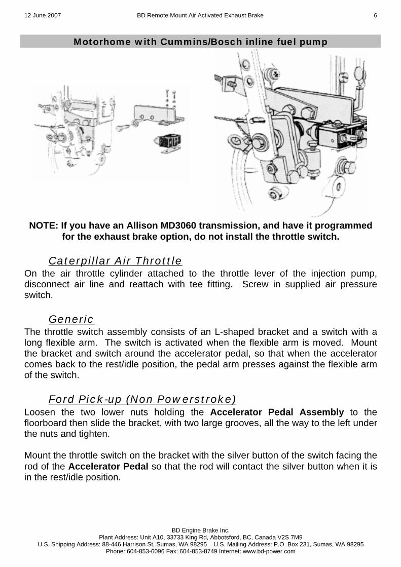
For 6spd manual transmission only To obtain access to the Cruise Control wiring harness, remove the lower steering column panel by removing the mounting screws and unsnapping the panel from the instrument panel.
Under the dash running vertical by the left of the steering column, locate the smaller wiring harness that runs out of the main harness. Remove some of the black electrical tape to gain access to the smaller wire bundle.
***DANGER*** THERE IS A BLACK WIRE WITH A TWISTED LIGHT BLUE/GREEN TRACER DO NOT CONNECT OR TEST THIS WIRE AS IT IS CONNECTED TO THE AIR BAG
AND THE BAG MAY DEPLOY CAUSING DAMAGE AND/OR INJURY. Remove some of the black electrical tape from the small bundle to gain access to the small Black wire with Light Blue tracer and install a gray Posi-Tap to it. Insert the Blue wire from the DFIV module into this connector. In this same wiring harness, locate the Red wire with Light Green tracer and install another Gray Posi-Tap. Insert the Green wire from the DFIV module into this connector.

12 June 2007 BD Remote Mount Air Activated Exhaust Brake
BD Engine Brake Inc. Plant Address: Unit A10, 33733 King Rd, Abbotsford, BC, Canada V2S 7M9
U.S. Shipping Address: 88-446 Harrison St, Sumas, WA 98295 U.S. Mailing Address: P.O. Box 231, Sumas, WA 98295 Phone: 604-853-6096 Fax: 604-853-8749 Internet: www.bd-power.com
11
For all applications Locate a grommet on the firewall and cut an opening in it to run the wiring through the firewall. Route the Yellow wire from the DFIV module along the driver side of the engine to the throttle linkage and APPS Sensor. Remove the cover of the throttle linkage then locate and disconnect the wiring connector for the APPS. NOTE: This connector is located on the underside of the throttle linkage assembly and is in a difficult position. Open the loom and locate the Light Blue w/Black wire and install a Gray Posi-Tap to it. Connect the Yellow wire from the DFIV Module to this Posi-Tap and reconnect the APPS connector then reinstall the throttle linkage cover.
Dodge - 1988 to 1993 The Throttle Switch Bracket mounts behind the throttle linkage located on the driver side, behind the injection pump. Mount the throttle switch on the bracket with the switch on the outside of the bracket but do not fully tighten the screws. Secure the throttle switch bracket to the engine using two bolts. If the throttle spring(s) are weak, another spring may have to be installed.
12 June 2007 BD Remote Mount Air Activated Exhaust Brake
BD Engine Brake Inc. Plant Address: Unit A10, 33733 King Rd, Abbotsford, BC, Canada V2S 7M9
U.S. Shipping Address: 88-446 Harrison St, Sumas, WA 98295 U.S. Mailing Address: P.O. Box 231, Sumas, WA 98295 Phone: 604-853-6096 Fax: 604-853-8749 Internet: www.bd-power.com
12
Chev/GMC 1994-Present Below the throttle pedal you will need to remove the two nuts below the potentiometer, holding the Accelerator Pedal Assembly to the floor board, and mount the throttle switch bracket to the Accelerator Pedal Assembly with the two screws so that the bracket angles off to the right. Mount the throttle switch on the bracket, with the silver button of the switch facing the rod of the Accelerator Pedal, so that the rod will hit the silver button when it is in its resting/idle position. NOTE: 1993 and older Chev/GMC will use the Generic throttle switch. On all applications Manually move the linkage back and forth to ensure the proper activation of the throttle switch. The throttle switch may have to be adjusted on occasion. Note: With mechanical injection pump systems, the linkage is moved during cruise control and/or fast idle operations, so the switch should not be activated during these occurrences. Electronic throttles: advise driver that the brake should be turned off during cruise control operations. Cut a length of wire to go from the throttle switch to the Control Box Assembly. Using a female bullet style electrical connector, connect the wire to the free wire coming from Pressure Switch in the box, which has a male bullet style connector on it. Route the wire over to the throttle switch, out of the way of moving parts, and connect to the throttle switch.
12 June 2007 BD Remote Mount Air Activated Exhaust Brake
BD Engine Brake Inc. Plant Address: Unit A10, 33733 King Rd, Abbotsford, BC, Canada V2S 7M9
U.S. Shipping Address: 88-446 Harrison St, Sumas, WA 98295 U.S. Mailing Address: P.O. Box 231, Sumas, WA 98295 Phone: 604-853-6096 Fax: 604-853-8749 Internet: www.bd-power.com
13
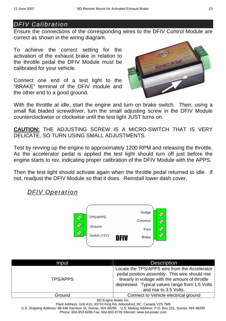
DFIV Calibration Ensure the connections of the corresponding wires to the DFIV Control Module are correct as shown in the wiring diagram. To achieve the correct setting for the activation of the exhaust brake in relation to the throttle pedal the DFIV Module must be calibrated for your vehicle. Connect one end of a test light to the “BRAKE” terminal of the DFIV module and the other end to a good ground. With the throttle at idle, start the engine and turn on brake switch. Then, using a small flat bladed screwdriver, turn the small adjusting screw in the DFIV Module counterclockwise or clockwise until the test light JUST turns on. CAUTION: THE ADJUSTING SCREW IS A MICRO-SWITCH THAT IS VERY DELICATE, SO TURN USING SMALL ADJUSTMENTS. Test by revving up the engine to approximately 1200 RPM and releasing the throttle. As the accelerator pedal is applied the test light should turn off just before the engine starts to rev, indicating proper calibration of the DFIV Module with the APPS. Then the test light should activate again when the throttle pedal returned to idle. If not, readjust the DFIV Module so that it does. Reinstall lower dash cover.
DFIV Operation
Input Description
TPS/APPS
Locate the TPS/APPS wire from the Accelerator pedal position assembly. This wire should rise linearly in voltage with the amount of throttle
depressed. Typical values range from 1.5 Volts and rise to 3.5 Volts.
Ground Connect to Vehicle electrical ground

12 June 2007 BD Remote Mount Air Activated Exhaust Brake
BD Engine Brake Inc. Plant Address: Unit A10, 33733 King Rd, Abbotsford, BC, Canada V2S 7M9
U.S. Shipping Address: 88-446 Harrison St, Sumas, WA 98295 U.S. Mailing Address: P.O. Box 231, Sumas, WA 98295 Phone: 604-853-6096 Fax: 604-853-8749 Internet: www.bd-power.com
14
Switch (12V) This connection will supply 12 volt power to the DFIV. This will usual come from an output of a
switch.
Dodge This input should only be used for Dodge
applications as it disables the cruise control specifically for Dodge trucks.
Common Common cruise inputs between the Dodge and Ford inputs. The second cruise wire should be
connected here.
Ford
This input can be used for other generic applications. When the brake is activate the connection between the Ford input and the
Common are severed.
Brake
This is the 12 Volt output of the DFIV. Once the throttle has come to a rest at the idle position and the switch is provide power and the pedal adjustment is correct the DFIV will power the
brake.

12 June 2007 BD Remote Mount Air Activated Exhaust Brake
BD Engine Brake Inc. Plant Address: Unit A10, 33733 King Rd, Abbotsford, BC, Canada V2S 7M9
U.S. Shipping Address: 88-446 Harrison St, Sumas, WA 98295 U.S. Mailing Address: P.O. Box 231, Sumas, WA 98295 Phone: 604-853-6096 Fax: 604-853-8749 Internet: www.bd-power.com
15

12 June 2007 BD Remote Mount Air Activated Exhaust Brake
BD Engine Brake Inc. Plant Address: Unit A10, 33733 King Rd, Abbotsford, BC, Canada V2S 7M9
U.S. Shipping Address: 88-446 Harrison St, Sumas, WA 98295 U.S. Mailing Address: P.O. Box 231, Sumas, WA 98295 Phone: 604-853-6096 Fax: 604-853-8749 Internet: www.bd-power.com
16
Power Switch & Optional Gauge Mount the toggle switch (automatic transmissions) in a convenient location in the dash, or mount the push/pull switch (manual transmissions) on the shifter lever, using the switch clamp, and secure its cable on the lever. Locate a wire under the dash, which is a 12v ignition switched source, and then connect the in-line fuse connector to that wire with a line tapper. Using a butt connector, attach a section wire to the in-line fuse holder and cut enough length for the wire reach the toggle switch or push/pull switch cable, and connect using appropriate electrical connector. Cut another piece of wire to go from the switch/cable to the throttle switch.
On the toggle switch, there is a third terminal marked Amber, ground this terminal. Run the wire and attach to the switches using appropriate connectors. Attach and run black plastic tubing from the free compression fitting (no red markings) on the tee fitting of the Control Box Assembly, to where the gauge is going to be mounted. The kit comes with a bracket to mount the gauge under the dash, but it could be mounted in any optional 2” gauge mount. Connect the black plastic tubing to the back of the gauge using a 1/8npt female compression fitting. Using electrical connectors, connect the wire coming from the light bulb holder to a power source, preferable to one that is switched by the head light switch, and connect a ground wire to the mount screws of the gauge. Mount the gauge in the desired location.

12 June 2007 BD Remote Mount Air Activated Exhaust Brake
BD Engine Brake Inc. Plant Address: Unit A10, 33733 King Rd, Abbotsford, BC, Canada V2S 7M9
U.S. Shipping Address: 88-446 Harrison St, Sumas, WA 98295 U.S. Mailing Address: P.O. Box 231, Sumas, WA 98295 Phone: 604-853-6096 Fax: 604-853-8749 Internet: www.bd-power.com
17
Optional Shifter Switch To install the optional Manual Shifter Switch Kit, mount the switch onto the shift lever using the clamp supplied. Run the cable down the shifter shaft, securing the cable with zip-ties or electrical tape, and run under the carpet to the firewall and under the dash to the relays, leaving enough slack for proper shifting of the transmission lever and to prevent any rubbing of wire. At the end of the cable, cut off any excess and strip away about 1 to 2 inches of the black rubber covering, exposing the black and white (or Green) wires then strip the insulation from the ends of the two wires. Connect the White (or Green) wire to the “Switch” terminal on the DFIV Module. Attach a male blade connector to the Black wire. Remove the fused Red wire from the toggle switch (the toggle switch and remaining Red and Black wire attached to the switch will no longer be needed) and attach to the Black wire from the optional switch to the female connector of the fused Red wire. Locate one of the ignition switched red/black tracer wires under the steering column (one is 10/12ga and the other is 14/16ga) and connect an appropriate Posi-Tap connector to it (green for 10/12ga and black for the 14/16ga wire) then connect the fused Red wire to this Posi-Tap.

12 June 2007 BD Remote Mount Air Activated Exhaust Brake
BD Engine Brake Inc. Plant Address: Unit A10, 33733 King Rd, Abbotsford, BC, Canada V2S 7M9
U.S. Shipping Address: 88-446 Harrison St, Sumas, WA 98295 U.S. Mailing Address: P.O. Box 231, Sumas, WA 98295 Phone: 604-853-6096 Fax: 604-853-8749 Internet: www.bd-power.com
18
Cruise Disable Function
Chevy/GMC (1994-up) For 1994-up Chevrolets you will need to utilize the relay that is provided in the kit to connect the Cruise Control disable system. On 1994-up Chevrolets, right below the steering column, under the dash, there is a wire connector assembly with a large amount of wires connected to it. One of the purple wires leads up to another 8-pin connector just above it. You can verify the wire by tapping the wire with a test light and grounding the clip; with the ignition turned on, the light should be on, but, no light when you press on the brake pedal. Cut this wire and connect both ends (Dia. 9) to the Purple (or Blue) wires coming from the supplied relay using un-insulated butt connectors and shrink wrap. Of the two remaining wires on the relay, the Yellow wire connects to the same terminal on the Throttle Switch as the wire coming from the Toggle or Shifter switch. Mount the relay under the dash and ground the Black wire.
Ford Locate the Black w/Yellow wire at the Cruise Control Disable (Brake Applied) switch located on the brake master cylinder and expose the wiring approximately 4 to 6 inches from the switch to allow for a good length to work with. NOTE: This wire may be a different color in various applications. If there is no Black w/Yellow wire going to this switch, use a test light to check which wire changes state (power to no power) when the brake pedal is applied. Cut the Black wire w/Yellow tracer (BK/Y), then strip both ends and attach a male bullet connector on one end and a female bullet connector on the other. (NOTE: It does not matter which wire the male or female connector goes on.) Run the Green and Blue wires that were brought through the firewall to the Brake Applied Switch at the brake booster and cut off any excess. Attach a male bullet connector to one of these wires and attach a female bullet connector to the other wire. Connect these to the connectors just attached to the Black wire w/Yellow tracer.

12 June 2007 BD Remote Mount Air Activated Exhaust Brake
BD Engine Brake Inc. Plant Address: Unit A10, 33733 King Rd, Abbotsford, BC, Canada V2S 7M9
U.S. Shipping Address: 88-446 Harrison St, Sumas, WA 98295 U.S. Mailing Address: P.O. Box 231, Sumas, WA 98295 Phone: 604-853-6096 Fax: 604-853-8749 Internet: www.bd-power.com
19

12 June 2007 BD Remote Mount Air Activated Exhaust Brake
BD Engine Brake Inc. Plant Address: Unit A10, 33733 King Rd, Abbotsford, BC, Canada V2S 7M9
U.S. Shipping Address: 88-446 Harrison St, Sumas, WA 98295 U.S. Mailing Address: P.O. Box 231, Sumas, WA 98295 Phone: 604-853-6096 Fax: 604-853-8749 Internet: www.bd-power.com
20
Exhaust Brake Testing Turn the ignition to the first position and turn the power switch on to make sure the brake activates. If the brake does not activate or operates very slow, start the vehicle and try the operation again (Low air pressure will result in lack of operation while vehicle is turned off). Depress the throttle pedal and let up on it to check the operation of the throttle switch, allowing the brake to engage when the throttle is in the resting/idle position. The brake pressure at idle may have to be adjusted to accommodate your system. If a Brake Pressure gauge is installed check the rating of the Pressure Switch on the Control Box Assembly, the tag will have a pressure value or it may even be written in red paint on the tee fitting. If it is below 40 psi, adjust the pressure regulator on the Pump Assembly so that the pressure reads between 4-6 lbs at idle. For ratings of 40 - 50 psi, then adjust for 6-10 lbs at idle. And pressure ratings above 50 psi, adjust for 10-15 psi at idle. 3208 Cat applications can only be set on the road; pressure should be 0 psi at idle, 28 psi in 3rd gear at 2500 rpm, and 20 psi at 2200 rpm. This idle pressure adjustment can be made by adjusting the stop bolt mounted on the exhaust brake support bracket. Loosen the stop nut and turn the bolt clockwise for less pressure and counter-clockwise for more idle pressure. Be sure to tighten the stop bolt once your adjustments are done. Note that brake’s warranty will be voided if it is found that the exhaust valve comes in contact with valve casting. To avoid this be sure the stop bolts is infact providing a limit for the valve. Maintenance The brake valve requires periodic maintenance to free up the flap and remove carbon build up or rusting due to condensation in the exhaust, as well as adjustment of linkages. To prevent premature service or seizing of the valve, we suggest continual use of the brake or refrain from extended periods of non-usage. With condensation build up or dirt in the air lines, the electric air valve may have to be taken apart to be cleaned. The backpressure line will require blowing out (from Control Valve to Brake Valve) once or twice a year.

12 June 2007 BD Remote Mount Air Activated Exhaust Brake
BD Engine Brake Inc. Plant Address: Unit A10, 33733 King Rd, Abbotsford, BC, Canada V2S 7M9
U.S. Shipping Address: 88-446 Harrison St, Sumas, WA 98295 U.S. Mailing Address: P.O. Box 231, Sumas, WA 98295 Phone: 604-853-6096 Fax: 604-853-8749 Internet: www.bd-power.com
21
Trouble Shooting If problem occurs with operation of unit, then consult list below.
Complaint Cause Check/Correction
Brake slow to operate Low or no air pressure Check air source. Clean electric air valve.
Delayed release Hose too long Ensure hose is 4ft or shorter in length
Brake valve cycles excessively Valve pressure set too high Adjust valve to open more, with
lower brake pressure at idle.
Braking performance not effective
Valve set too low or drive train problem
Check effect in lower gear. Check automatic trans stall speed. Adjust valve to close more for increased pressure at idle.
Brake quit operating Electrical problem
Check fuse at in-line fuse holder. Check function of throttle switch. Check power at connections between line-tap and Control Box.
Gauge not reading, but brake working Plugged pressure line
Disconnect pressure line from Control Box and blow compressed air through pressure line.
Brake valve seized Valve needs service Service valve.

12 June 2007 BD Remote Mount Air Activated Exhaust Brake
BD Engine Brake Inc. Plant Address: Unit A10, 33733 King Rd, Abbotsford, BC, Canada V2S 7M9
U.S. Shipping Address: 88-446 Harrison St, Sumas, WA 98295 U.S. Mailing Address: P.O. Box 231, Sumas, WA 98295 Phone: 604-853-6096 Fax: 604-853-8749 Internet: www.bd-power.com
22
If a problem still occurs, then please call our BD Technical Department Monday to Friday, 8:00am to 4:30pm Pacific Time at 1-800-887-5030 or (604) 853-6096. Or we can be reached by fax at (604) 853-8749.

12 June 2007 BD Remote Mount Air Activated Exhaust Brake
BD Engine Brake Inc. Plant Address: Unit A10, 33733 King Rd, Abbotsford, BC, Canada V2S 7M9
U.S. Shipping Address: 88-446 Harrison St, Sumas, WA 98295 U.S. Mailing Address: P.O. Box 231, Sumas, WA 98295 Phone: 604-853-6096 Fax: 604-853-8749 Internet: www.bd-power.com
23
Cummins 5.9L Turbo Mount Exhaust Brake Addendum
For installation of Turbo Mount valve, hold valve with adapter pipe up to turbo to estimate where to cut stock exhaust, keeping in mind that the adapter pipe will slide into the stock exhaust pipe. Remove and retain the turbo exhaust clamp securing the exhaust pipe to the turbo. Cut the exhaust at the estimated spot. Securely bolt the adapter pipe to the Turbo Mount valve and push adapter pipe into stock exhaust. Inspect turbo exhaust clamp and turbo outlet for any carbon build up or damage that may cause problems sealing on exhaust mating surfaces. Install Turbo Mount valve onto turbo outlet using the stock turbo clamp, and then seal clamp (or weld) the adapter pipe and the stock exhaust together. All other instructions in this manual will remain in effect for this installation. THIS KIT MAY ALSO REQUIRE THE ADAPTER #1040037 ON SOME 1999 AND UP MODEL MOTORHOMES.

12 June 2007 BD Remote Mount Air Activated Exhaust Brake
BD Engine Brake Inc. Plant Address: Unit A10, 33733 King Rd, Abbotsford, BC, Canada V2S 7M9
U.S. Shipping Address: 88-446 Harrison St, Sumas, WA 98295 U.S. Mailing Address: P.O. Box 231, Sumas, WA 98295 Phone: 604-853-6096 Fax: 604-853-8749 Internet: www.bd-power.com
24
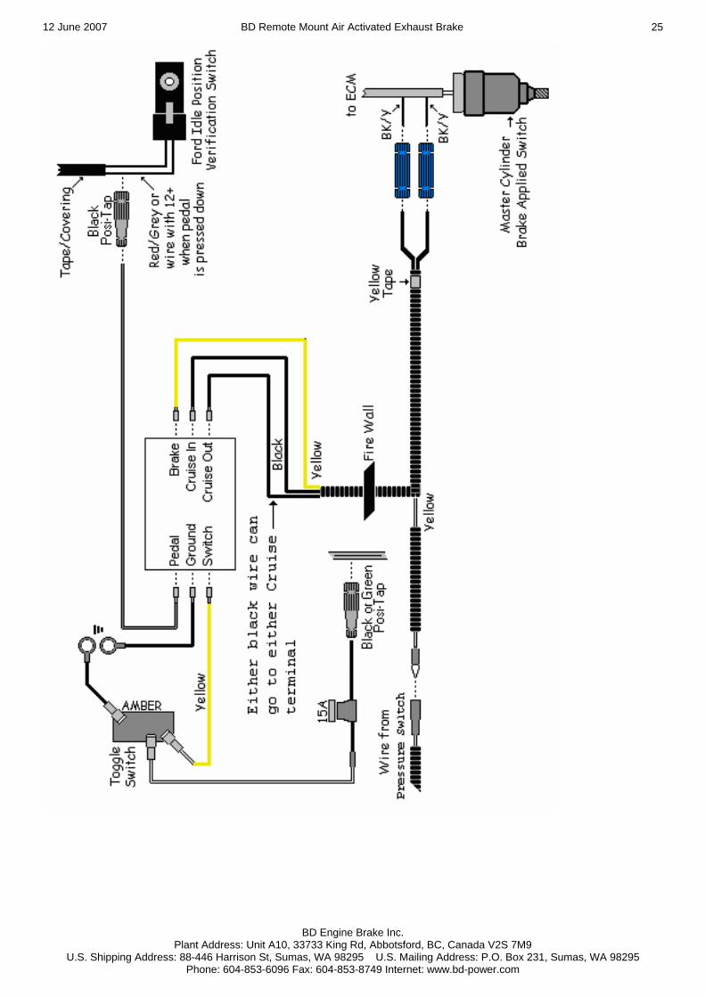
Additional Wiring Instructions (Ford Powerstroke) Take off the lower panel below the steering column. Mount the relays and ground the wires from terminal # 85 on both relays to the steel cross brace. On the Throttle Pedal Assembly, there is an Idle Position Verification Switch (with two wires connected) that is pressed in when the Throttle Pedal is at rest/idle. Strip away approximately 1 (one) inch of the tape/covering around the two wires going to the switch. Attach the Red wire, coming from the two relays, to the Red wire with Gray tracer (R/G) on the Idle Verification Switch using a line tapper. The wire that needs to be tapped will have 12 volts on it when the throttle pedal is pushed down. For the Powerstroke’s that have Cruise Control, locate the Brake Applied Switch on top of the Hydraulic Brake Master Cylinder. Expose the two wires, about 3 to 6 inches from the switch, and cut the Black wire with Yellow tracer (BK/Y) and strip both ends. Attach a male bullet connector to one end and a female bullet connector to the other. NOTE: It does not matter which end the male or female connector goes on. Run the two long Black wires from the relays, through the firewall, to the wires you just attached the bullet connectors to. Using a line tapper, connect the fused wire from the Toggle Switch to one of the Red wires with Black tracer (R/B) that are in the group of wires under the steering column. Ground the Black wire coming from the Toggle Switch.
12 June 2007 BD Remote Mount Air Activated Exhaust Brake
BD Engine Brake Inc. Plant Address: Unit A10, 33733 King Rd, Abbotsford, BC, Canada V2S 7M9
U.S. Shipping Address: 88-446 Harrison St, Sumas, WA 98295 U.S. Mailing Address: P.O. Box 231, Sumas, WA 98295 Phone: 604-853-6096 Fax: 604-853-8749 Internet: www.bd-power.com
25

12 June 2007 BD Remote Mount Air Activated Exhaust Brake
BD Engine Brake Inc. Plant Address: Unit A10, 33733 King Rd, Abbotsford, BC, Canada V2S 7M9
U.S. Shipping Address: 88-446 Harrison St, Sumas, WA 98295 U.S. Mailing Address: P.O. Box 231, Sumas, WA 98295 Phone: 604-853-6096 Fax: 604-853-8749 Internet: www.bd-power.com
26
Caterpillar 3116/3126/3126B Vehicles WITHOUT an Allison WT transmission WITHOUT ABS braking WITH an on-board air system
NOTE: • *View shown is looking at the harness side of the connector. • Relay shown is de-energized. • Information from this schematic was derived from vehicle systems at the date of this printing.

12 June 2007 BD Remote Mount Air Activated Exhaust Brake
BD Engine Brake Inc. Plant Address: Unit A10, 33733 King Rd, Abbotsford, BC, Canada V2S 7M9
U.S. Shipping Address: 88-446 Harrison St, Sumas, WA 98295 U.S. Mailing Address: P.O. Box 231, Sumas, WA 98295 Phone: 604-853-6096 Fax: 604-853-8749 Internet: www.bd-power.com
27
OPERATING GUIDELINES Thank you for taking interest in the BD Engine Exhaust Brake. As a driver, you probably already know the need for extra braking power that your vehicle requires on hills and long grades. With loads being towed behind you, the extra push when slowing down or maintaining speed on downward grades can prove to be a great strain on your vehicle’s chassis brake system, even to the point of “burn-up”. These guidelines were designed to offer you a better understanding of the benefits of exhaust brakes and are partly based upon material developed by the U.S. Department of Transportation National Highway Traffic Safety Administration. The emphasis on today’s vehicles is to give the consumer a product that can give them usable power with fuel efficiency. But, in the transition, the vehicles have lost their natural braking power, making it more easy for the vehicle to continue to roll and harder to stop. Of course, this gets more noticeable with the increase of weight, on or behind the vehicle. This is where an exhaust brake becomes a useful tool in increasing the driveline drag of the vehicle without the use of the chassis brakes. A tool that with maximum or even occasional use can reduce wear on chassis brake parts and at the same time increase safety. The BD Exhaust Brake can be used to help maintain a controlled vehicle speed on a downward grade, as well as slowing the vehicle down at such times as turns or exit ramps, without you using your chassis brakes. But, the exhaust brake cannot be used as a parking brake or will not bring your vehicle to a complete stop. By using a BD Exhaust Brake, the life and effectiveness of your chassis brakes will increase. This is because of the decreased use of the chassis brakes in situations like hills, the wear factor is reduced and there is less opportunity for your chassis brakes to heat up which would reduce the efficiency. When you ride your chassis brakes, make hard stops or have poorly adjusted brakes, this creates high temperatures and as your brakes get hotter, the more chance there is for fade or failure. With terrain that is a series of up and down grades, the BD Exhaust Brake will aid in reducing exhaust valve warping. Because of the power needed to pull your vehicle and load up a hill, a lot of heat is generated. When you have reached the crest of the hill and are now coasting down the other side, the heated valves are cooled too quickly. With the exhaust brake engaged, the heat loss to the valves will be reduced, which can prevent valve warping. When the toggle switch is turned to the “On” position, the valve is activated every time the driver takes his foot off of the throttle pedal. When the driver puts pressure back on the throttle pedal, the micro-switch is deactivated and the valve opens again. Exhaust brakes are designed to operate with the throttle at idle, not to be

12 June 2007 BD Remote Mount Air Activated Exhaust Brake
BD Engine Brake Inc. Plant Address: Unit A10, 33733 King Rd, Abbotsford, BC, Canada V2S 7M9
U.S. Shipping Address: 88-446 Harrison St, Sumas, WA 98295 U.S. Mailing Address: P.O. Box 231, Sumas, WA 98295 Phone: 604-853-6096 Fax: 604-853-8749 Internet: www.bd-power.com
28
used in conjunction with cruise controls, and not designed to aid in gear shifting. Such cases could cause damage to engine and/or the exhaust brake. On the BD Exhaust Brake, there is a Pressure Switch installed to monitor the created back pressure. If the back pressure reaches the set limit, the switch cuts power to the system until the back pressure comes back down below the limit. The pressure switches are set for each engine type, and are not adjustable. If you have purchased a system that is rated for the stock engine exhaust valve springs, and you later decide to update to the heavy duty exhaust valve springs, you will have to replace the Pressure Switch to achieve the 60 lb. capacity. Never install a 60 lb. system on an engine that has not had the heavy duty engine exhaust valve springs installed first. The best scenario for exhaust braking is when going down hill, select a gear that lets you maintain a constant speed with little or no use of the chassis brakes, or the same gear that would be used to go up the same grade of hill. This also depends on the weight, load, or road conditions that the vehicle will come upon. The BD Exhaust Brake was not designed for use in overdrive, so when braking is required, make sure the overdrive is off. So, in summary, by using the BD Exhaust Brake, you reduce the need for use of your chassis brakes in situations where you need to slow down or maintain speed (i.e. hills, off ramps, corners, approaching speed changes or traffic lights). By reducing the use of your chassis brakes in these situations, this reduces the heat build up, as well as wear and damage to linings and drums. And, when you reduce these factors, you save your chassis brakes for when you really need them (i.e. for stopping or emergencies). The BD Exhaust Brake is not a substitute for your chassis brakes and, cannot correct or compensate for poorly maintained or misadjusted brakes. But, when you need to slow down or maintain a constant speed, the BD Exhaust Brake will be a valuable and effective tool. Exhaust Brakes are more efficient at preventing than correcting and over speed condition. To increase the life of your exhaust brake we recommend daily operation. This could simply be switching it on and off a couple times a day. This will prevent the butterfly from sticking due to carboning up. Pressure tubing from Valve Assembly to Pressure Switch should be blown out with pressurized air on occasion (see Maintenance & Trouble Shooting).

12 June 2007 BD Remote Mount Air Activated Exhaust Brake
BD Engine Brake Inc. Plant Address: Unit A10, 33733 King Rd, Abbotsford, BC, Canada V2S 7M9
U.S. Shipping Address: 88-446 Harrison St, Sumas, WA 98295 U.S. Mailing Address: P.O. Box 231, Sumas, WA 98295 Phone: 604-853-6096 Fax: 604-853-8749 Internet: www.bd-power.com
29
OPTIONS Description Part Number# BD Performance Torque Convertor CALL 60lb. Exhuast Valve Spring Kit 1030060 Performance Injectors CALL Brake Pressure Gauge Kit (Dodge) 1030550 Brake Pressure Gauge Kit (Ford) 1030551 Brake Pressure Gauge Kit (Chevy) 1030552 Exhaust Temperature Gauge 1030512 Cockpit Gauge Mount (Single) 1030600

12 June 2007 BD Remote Mount Air Activated Exhaust Brake
BD Engine Brake Inc. Plant Address: Unit A10, 33733 King Rd, Abbotsford, BC, Canada V2S 7M9
U.S. Shipping Address: 88-446 Harrison St, Sumas, WA 98295 U.S. Mailing Address: P.O. Box 231, Sumas, WA 98295 Phone: 604-853-6096 Fax: 604-853-8749 Internet: www.bd-power.com
30
BD ENGINE BRAKE, INC. LIMITED WARRANTY STATEMENT
THE INSTALLATION OF THIS PRODUCT INDICATES THAT THE BUYER HAS READ AND UNDERSTANDS THIS AGREEMENT AND ACCEPTS ITS TERMS AND CONDITIONS.
DISCLAIMER OF LIABILITY
BD Engine Brake Inc., its successors, distributors, jobbers, and dealers (hereafter “BD”) shall in no way be responsible for the product's proper use and service. THE BUYER HEREBY WAIVES ALL LIABILITY CLAIMS. BD disclaims any warranty and expressly disclaims any liability for personal injury or damages. BD also disclaims any liability for incidental or consequential damages including, but not limited to, repair labor, rental vehicles, hotel costs, or any other inconvenience costs by reason of use or sale of any such equipment. The BUYER acknowledges and agrees that the disclaimer of any liability for personal injury is a material term for this agreement and the BUYER agrees to indemnify BD and to hold BD harmless from any claim related to the item of any equipment purchased. This warranty shall not apply to any unit that has been improperly stored or installed, or to misapplication, improper operation conditions, accidents, neglect, or which has been improperly repaired or altered or otherwise mistreated by the BUYER or his agent. BD also assumes no liability regarding the improper installation or misapplication of its products. It is the installer's responsibility to check for proper installation and if in doubt, contact the manufacturer.
LIMITATION OF WARRANTY BD Engine Brake Inc. (hereafter "BD") warrants to the BUYER that any parts purchased shall be free from defects in material workmanship. A defect is defined as a condition within the product that would render the product inoperable. BD gives Limited Warranty as to description, quality, merchantability, fitness for any product’s purpose, productiveness, or any other matter of BD's product sold herewith. BD shall be in no way responsible for the product’s open use and service and the BUYER hereby waives all rights other than those expressly written herein. This Warranty shall not be extended or varied except by a written instrument signed by BD and the BUYER. The Warranty is Limited to two (2) years from the date of sale. Labor costs incurred by the removal and replacement of the BD product, while performing warranty work, will be covered for 1 (one) year, payable at BD rates, at authorized centers and with prior approval. Until BD has approved the claim, the consumer may be responsible for these costs. A Return Authorization (WA) number, obtained in advance from BD, must accompany all products returned for warranty consideration. All products must be returned, shipping prepaid, to BD and must be accompanied by a dated proof of purchase receipt. All Warranty claims are subject to approval by BD and repaired or replaced product will be returned to the customer freight collect. Accepted warranty units, which have been replaced, become the sole property of BD. This warranty is in lieu of all other warranties or guaranties, either expressed or implied, and shall not extend to any consumer or to any person other than the original purchaser residing within the boundaries of the continental U.S. or Canada. IN THE EVENT THAT THE BUYER DOES NOT AGREE WITH THIS AGREEMENT, THE BUYER MAY PROMPTLY RETURN THIS PRODUCT, IN A NEW AND UNUSED CONDITION, WITH A DATED PROOF OF PURCHASE, TO THE PLACE OF PURCHASE WITHIN THIRTY (30) DAYS FROM DATE OF PURCHASE FOR A FULL REFUND.