Embed Size (px)
Citation preview
8/7/2019 Bcr320u_bcr321u Led Driver
http://slidepdf.com/reader/full/bcr320ubcr321u-led-driver 1/12
2010-01-151
BCR320U / BCR321U
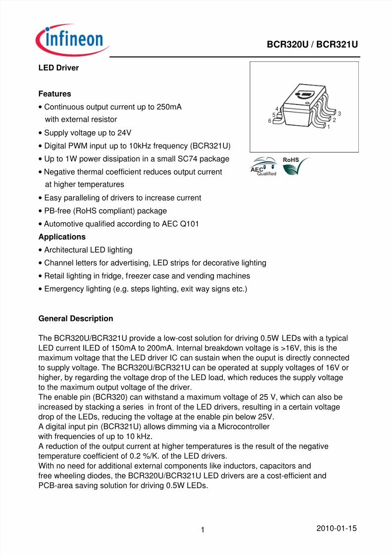
LED Driver
Features• Continuous output current up to 250mA
with external resistor• Supply voltage up to 24V• Digital PWM input up to 10kHz frequency (BCR321U)• Up to 1W power dissipation in a small SC74 package• Negative thermal coefficient reduces output current
at higher temperatures• Easy paralleling of drivers to increase current• PB-free (RoHS compliant) package• Automotive qualified according to AEC Q101
Applications• Architectural LED lighting• Channel letters for advertising, LED strips for decorative lighting• Retail lighting in fridge, freezer case and vending machines•
Emergency lighting (e.g. steps lighting, exit way signs etc.)
54
63
21
General Description The BCR320U/BCR321U provide a low-cost solution for driving 0.5W LEDs with a typicalLED current ILED of 150mA to 200mA. Internal breakdown voltage is >16V, this is themaximum voltage that the LED driver IC can sustain when the ouput is directly connectedto supply voltage. The BCR320U/BCR321U can be operated at supply voltages of 16V orhigher, by regarding the voltage drop of the LED load, which reduces the supply voltage
to the maximum output voltage of the driver.The enable pin (BCR320) can withstand a maximum voltage of 25 V, which can also beincreased by stacking a series in front of the LED drivers, resulting in a certain voltagedrop of the LEDs, reducing the voltage at the enable pin below 25V.A digital input pin (BCR321U) allows dimming via a Microcontrollerwith frequencies of up to 10 kHz.A reduction of the output current at higher temperatures is the result of the negativetemperature coefficient of 0.2 %/K. of the LED drivers.With no need for additional external components like inductors, capacitors andfree wheeling diodes, the BCR320U/BCR321U LED drivers are a cost-efficient and
PCB-area saving solution for driving 0.5W LEDs.

8/7/2019 Bcr320u_bcr321u Led Driver
http://slidepdf.com/reader/full/bcr320ubcr321u-led-driver 2/12
2010-01-152
BCR320U / BCR321U
Typical ApplicationPin Configuration
BCR321U
Vdrop
Rext
4
6
2,3,51
+Vs
IEN IOUTEN
GND
µC
OUT
6 5 4
1 2 3
Type Marking Pin Configuration Package
BCR320U
BCR321U
30
31
1 = EN 2;3;5 =
OUT
4 = GND 6 = R ext SC74
SC74Maximum Ratings
Parameter Symbol Value Unit
Enable voltage
BCR320U
BCR321U
V EN
25
4.5
V
Output current I out 300 mA
Output voltageV
out16 V
Reverse voltage between all terminals V R 0.5
Total power dissipation, T S = 102 °C P tot 1000 mW
Junction temperature T j 150 °C
Storage temperature T stg -65 ... 150
Thermal Resistance
Parameter Symbol Value Unit
Junction - soldering point 1) R thJS 50 K/W
1For calculation of R thJA please refer to Application Note Thermal Resistance

8/7/2019 Bcr320u_bcr321u Led Driver
http://slidepdf.com/reader/full/bcr320ubcr321u-led-driver 3/12
2010-01-153
BCR320U / BCR321U
Electrical Characteristics at T A=25°C, unless otherwise specified
Parameter Symbol Values Unitmin. typ. max.
Characteristics
Collector-emitter breakdown voltageI C = 1 mA, I B = 0
V BR(CEO) 16 - - V
Enable currentV EN = 12 , BCR320UV EN = 3.3 , BCR321U
I EN
-
-
1.2
1.2
-
-
mA
DC current gainI C = 50 mA, V CE = 1 V
h FE 200 350 500 -
Internal resistorI Rint = 10 mA
R int 65 90 105 Ω
Bias resistor
BCR320U
BCR321U
R B
-
-
10
1.5
-
-
kΩ
Output currentV out = 1.4 V, V EN = 12 V, BCR320UV out = 1.4 V, V EN = 3.3 V, BCR321UV out = 1.4 V, V EN = 12 V, R EXT = 3 Ω ,
BCR320UV out = 1.4 V, V EN = 3.3 , R EXT = 3 Ω ,
BCR321U
I out 8
8
-
-
10
10
250
250
12
12
-
-
mA
Voltage drop ( V Rext )I C = 10 mA
V drop 0.85 0.95 1.05 V
DC Characteristics with stabilized LED load
Lowest sufficient supply voltage overheadI out > 18mA
V Smin - 1.4 - V
Output current change versus T A V EN = 12 V; V out > 2.0 V, BCR320UV EN = 3.3 V; V out > 2.0 V, BCR321U
∆ I out / I out
-
-
-0.2
-0.2
-
-
%/K
Output current change versus V S V EN = 12 V; V out > 2.0 V, BCR320UV EN = 3.3 V; V out > 2.0 V, BCR321U
∆ I out / I out -
-
1
1
-
-
%/V

8/7/2019 Bcr320u_bcr321u Led Driver
http://slidepdf.com/reader/full/bcr320ubcr321u-led-driver 4/12
2010-01-154
BCR320U / BCR321U
Total power dissipation P tot = f (T S )
0 20 40 60 80 100 120 °C 150
TS
0
100
200
300
400
500
600
700
800
900
1000
mW1200
P t o t
Permissible Pulse Load R thJS = f (t p)
10 -6 10 -5 10 -4 10 -3 10 -2 10 0s
T P
-110
010
110
210
310
R t h J S
D = 0,50,20,10,050,020,010,0050
Permissible Pulse LoadP totmax / P totDC = f (t p)
10 -6 10 -5 10 -4 10 -3 10 -2 10 0s
T P
010
110
210
310
-
P t o t m a x / P t o t D C
D = 00.0050.010.020.050.10.20.5

8/7/2019 Bcr320u_bcr321u Led Driver
http://slidepdf.com/reader/full/bcr320ubcr321u-led-driver 5/12
2010-01-155
BCR320U / BCR321U
BCR320U: Output current versus R extI out = f (R ext ); V EN = 12 V;V out = Parameter
10 0 10 1 10 2Ohm
R ext.
0
0.02
0.04
0.06
0.08
0.1
0.12
0.14
0.16
0.18
0.2
0.22
A0.26
I o u t
Vout = 5.4VVout = 1.4V
BCR320U: Output current versus V outI out = f (V out ); V EN = 12 V;R ext = Parameter
0 2 4 6 8 V 12V out
0
0.1
A
0.3
I o u t
Rext = open
Rext = 20 Ohm
Rext = 10 Ohm
Rext = 6 Ohm
Rext = 4 Ohm
Rext = 3 Ohm
BCR320U: Output current versus V outI out = f (V S ); V EN = 12 V; R ext = open;T A= Parameter
0 2 4 6 8 V 12V out
0
0.005
0.01
A
0.02
I o u t
TA = -40°CTA = 25°CTA = 85°C
BCR320U: Output current versus V outI out = f (V S ); V EN = 12 V; R ext = 20 Ohm;T A= Parameter
0 2 4 6 8 V 12V out
0
0.01
0.02
0.03
0.04
0.05
0.06
0.07
0.08
A
0.1
I o u t
TA = -40°C
TA = 25°CTA = 85°C

8/7/2019 Bcr320u_bcr321u Led Driver
http://slidepdf.com/reader/full/bcr320ubcr321u-led-driver 6/12
2010-01-156
BCR320U / BCR321U
BCR320U: Output current versus V outI out = f (V S ); V EN = 12 V; R ext = 3 Ohm;T A= Parameter
0 2 4 6 8 V 12V out
0
0.1
0.2
0.3
A
0.5
I o u t
TA = 25°CTA = -40°CTA = 85°C
BCR320U: Output current versus V ENI out = f (V EN); V out = 2.0 V; R ext = open;T A = Parameter
0 5 10 15 V 25V EN
0
0.005
0.01
A
0.02
I o u t
TA = -40°CTA = 25°CTA = 85°C
BCR320U: Output current versus V ENI out = f (V EN); V out = 2.0 V; R ext = 20 Ohm;T A = Parameter
0 5 10 15 V 25V EN
0
0.01
0.02
0.03
0.04
A
0.06
I o u t
TA = -40°CTA = 25°CTA = 85°C
BCR320U: Output current versus V ENI out = f (V EN); V out = 2.0 V; R ext = 3 Ohm;T A = Parameter
0 5 10 15 V 25V EN
0
0.1
A
0.3
I o u t
TA = 85°CTA = 25°CTA = -40°C

8/7/2019 Bcr320u_bcr321u Led Driver
http://slidepdf.com/reader/full/bcr320ubcr321u-led-driver 7/12
2010-01-157
BCR320U / BCR321U
BCR320U: Enable current versus V ENI EN = f (V EN ); R ext = open; I out = 0;T A = Parameter
0 5 10 15 V 25V EN
0
0.5
1
1.5
2
mA
3
I E N
TA = 80°CTA = 25°CTA = -40°C
BCR320U: Output current versus V ENI out = f (V EN); V out = 2.0 V;R ext = Parameter
0 5 10 15 V 25V EN
0
0.1
A
0.3
I o u t
Rext = open
Rext = 20 Ohm
Rext = 10 Ohm
Rext = 6 Ohm
Rext = 4 Ohm
Rext = 3 Ohm
BCR321U: Output current versus V outI out = f (V out); V EN = 3.3 V;R ext = Parameter
0 2 4 6 8 V 12V out
0
0.1
A
0.3
I o u t
Rext = open
Rext = 20 Ohm
Rext = 10 Ohm
Rext = 6 Ohm
Rext = 4 Ohm
Rext = 3 Ohm
BCR321U: Output current versus R extI out = f (R ext); V EN = 3.3 V;V out = Parameter
10 0 10 1 10 2Ohm
R ext.
0
0.1
0.2
A
0.4
I o u t
Vout = 5.4VVout = 1.4V

8/7/2019 Bcr320u_bcr321u Led Driver
http://slidepdf.com/reader/full/bcr320ubcr321u-led-driver 8/12
8/7/2019 Bcr320u_bcr321u Led Driver
http://slidepdf.com/reader/full/bcr320ubcr321u-led-driver 9/12
2010-01-159
BCR320U / BCR321U
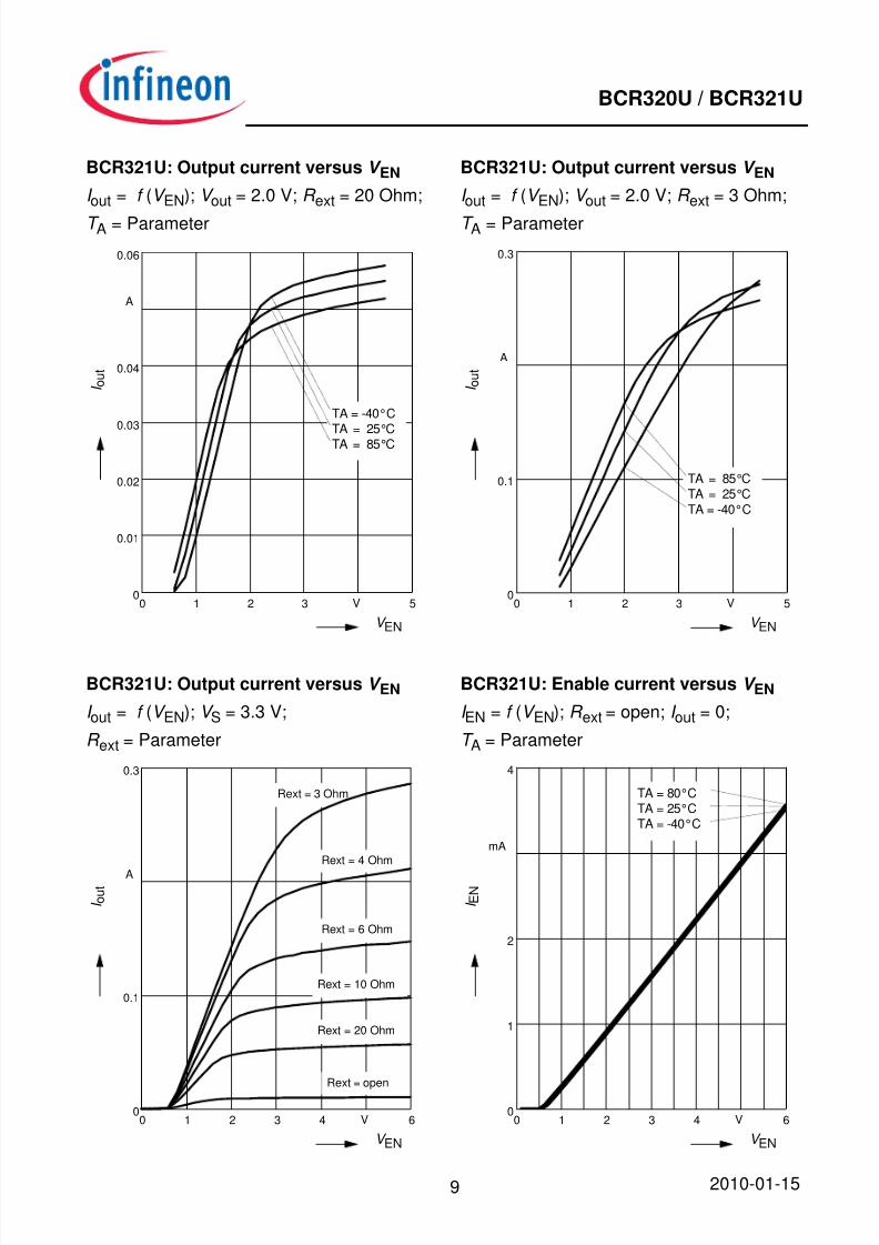
BCR321U: Output current versus V ENI out = f (V EN); V out = 2.0 V; R ext = 20 Ohm;T A = Parameter
0 1 2 3 V 5V EN
0
0.01
0.02
0.03
0.04
A
0.06
I o u t
TA = -40°CTA = 25°CTA = 85°C
BCR321U: Output current versus V ENI out = f (V EN); V out = 2.0 V; R ext = 3 Ohm;T A = Parameter
0 1 2 3 V 5V EN
0
0.1
A
0.3
I o u t
TA = 85°CTA = 25°CTA = -40°C
BCR321U: Output current versus V ENI out = f (V EN); V S = 3.3 V;R ext = Parameter
0 1 2 3 4 V 6V EN
0
0.1
A
0.3
I o u t
Rext = open
Rext = 20 Ohm
Rext = 10 Ohm
Rext = 6 Ohm
Rext = 4 Ohm
Rext = 3 Ohm
BCR321U: Enable current versus V ENI EN = f (V EN); R ext = open; I out = 0;T A = Parameter
0 1 2 3 4 V 6V EN
0
1
2
mA
4
I E N
TA = 80°CTA = 25°CTA = -40°C
8/7/2019 Bcr320u_bcr321u Led Driver
http://slidepdf.com/reader/full/bcr320ubcr321u-led-driver 10/12
2010-01-1510
BCR320U / BCR321U
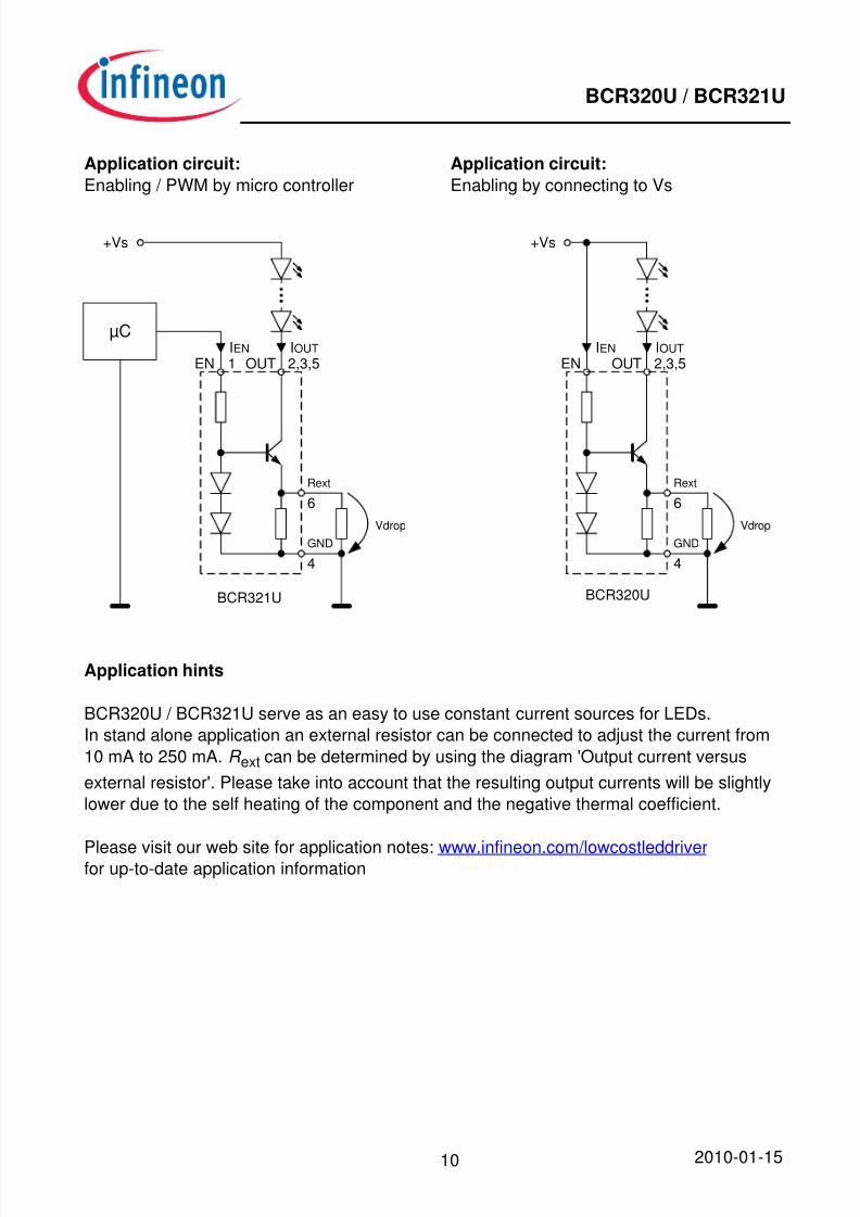
Application circuit:Enabling by connecting to Vs
Application circuit:Enabling / PWM by micro controller
BCR321U
Vdrop
Rext
4
6
2,3,51
+Vs
IEN IOUTEN
GND
µC
OUT
BCR320U
Vdrop
Rext
4
6
+Vs
GND
2,3,5IEN IOUT
EN OUT
Application hints BCR320U / BCR321U serve as an easy to use constant current sources for LEDs.In stand alone application an external resistor can be connected to adjust the current from10 mA to 250 mA. R ext can be determined by using the diagram 'Output current versusexternal resistor'. Please take into account that the resulting output currents will be slightlylower due to the self heating of the component and the negative thermal coefficient.
Please visit our web site for application notes: www.infineon.com/lowcostleddriverfor up-to-date application information

8/7/2019 Bcr320u_bcr321u Led Driver
http://slidepdf.com/reader/full/bcr320ubcr321u-led-driver 11/12
2010-01-1511
BCR320U / BCR321UPackage SC74
Package Out l ine
Foo t P r in t
S tanda rd Pack ing
0.5
0.95
1 . 9
2 . 9
5 46
321
1.1 MAX.
(0.35)(2.25)
±0.22.9 B
0.2+0.1-0.050.35
Pin 1marking
M B 6x0.95
1.9
0.15 -0.06+0.1
1 . 6
1 0 ˚ M A X
.
A
± 0
. 1
2 . 5
0 . 2
5
1 0 ˚ M A X
. ± 0
. 1
± 0
. 1
A0.2 M
0.1 MAX.
2 . 7
4
3.15Pin 1marking
8
0.2
1.15
Reel ø180 mm = 3.000 Pieces/ReelReel ø330 mm = 10.000 Pieces/Reel
For symmetric types no defined Pin 1 orientation in reel.
Manufacturer
2005, JuneDate code (Year/Month)
BCW66HType code
Pin 1 markingLaser marking
Mark ing Layou t (Example )
Small variations in positioning ofDate code, Type code and Manufacture are possible.

8/7/2019 Bcr320u_bcr321u Led Driver
http://slidepdf.com/reader/full/bcr320ubcr321u-led-driver 12/12
2010-01-1512
BCR320U / BCR321U
Edition 2009-11-16
Published byInfineon Technologies AG81726 Munich, Germany
2009 Infineon Technologies AGAll Rights Reserved.
Legal Disclaimer
The information given in this document shall in no event be regarded as a guaranteeof conditions or characteristics. With respect to any examples or hints given herein,any typical values stated herein and/or any information regarding the application ofthe device, Infineon Technologies hereby disclaims any and all warranties andliabilities of any kind, including without limitation, warranties of non-infringement ofintellectual property rights of any third party.
Information
For further information on technology, delivery terms and conditions and prices,please contact the nearest Infineon Technologies Office ( <www.infineon.com> ).
Warnings Due to technical requirements, components may contain dangerous substances.For information on the types in question, please contact the nearest InfineonTechnologies Office.Infineon Technologies components may be used in life-support devices or systems
only with the express written approval of Infineon Technologies, if a failure of suchcomponents can reasonably be expected to cause the failure of that life-supportdevice or system or to affect the safety or effectiveness of that device or system.Life support devices or systems are intended to be implanted in the human body orto support and/or maintain and sustain and/or protect human life. If they fail, it isreasonable to assume that the health of the user or other persons may beendangered.