Embed Size (px)
Citation preview
Relion® 670 series
Bay control REC670 2.0 IECCommissioning manual

Document ID: 1MRK511312-UENIssued: July 2016
Revision: BProduct version: 2.0
© Copyright 2014 ABB. All rights reserved
Copyright
This document and parts thereof must not be reproduced or copied without writtenpermission from ABB, and the contents thereof must not be imparted to a third party,nor used for any unauthorized purpose.
The software and hardware described in this document is furnished under a license andmay be used or disclosed only in accordance with the terms of such license.
This product includes software developed by the OpenSSL Project for use in theOpenSSL Toolkit. (http://www.openssl.org/)
This product includes cryptographic software written/developed by: Eric Young([email protected]) and Tim Hudson ([email protected]).
TrademarksABB and Relion are registered trademarks of the ABB Group. All other brand orproduct names mentioned in this document may be trademarks or registeredtrademarks of their respective holders.
WarrantyPlease inquire about the terms of warranty from your nearest ABB representative.

Disclaimer
The data, examples and diagrams in this manual are included solely for the concept orproduct description and are not to be deemed as a statement of guaranteed properties.All persons responsible for applying the equipment addressed in this manual mustsatisfy themselves that each intended application is suitable and acceptable, includingthat any applicable safety or other operational requirements are complied with. Inparticular, any risks in applications where a system failure and/or product failurewould create a risk for harm to property or persons (including but not limited topersonal injuries or death) shall be the sole responsibility of the person or entityapplying the equipment, and those so responsible are hereby requested to ensure thatall measures are taken to exclude or mitigate such risks.
This document has been carefully checked by ABB but deviations cannot becompletely ruled out. In case any errors are detected, the reader is kindly requested tonotify the manufacturer. Other than under explicit contractual commitments, in noevent shall ABB be responsible or liable for any loss or damage resulting from the useof this manual or the application of the equipment.

Conformity
This product complies with the directive of the Council of the European Communitieson the approximation of the laws of the Member States relating to electromagneticcompatibility (EMC Directive 2004/108/EC) and concerning electrical equipment foruse within specified voltage limits (Low-voltage directive 2006/95/EC). Thisconformity is the result of tests conducted by ABB in accordance with the productstandard EN 60255-26 for the EMC directive, and with the product standards EN60255-1 and EN 60255-27 for the low voltage directive. The product is designed inaccordance with the international standards of the IEC 60255 series.
Table of contents
Section 1 Introduction.......................................................................9This manual........................................................................................ 9Intended audience.............................................................................. 9Product documentation.....................................................................10
Product documentation set..........................................................10Dokumentenänderungsverzeichnis............................................. 11Related documents......................................................................12
Document symbols and conventions................................................12Symbols.......................................................................................12Document conventions................................................................13IEC 61850 edition 1 / edition 2 mapping......................................14
Section 2 Safety information.......................................................... 23Symbols on the product....................................................................23Warnings.......................................................................................... 23Caution signs....................................................................................25Note signs.........................................................................................25
Section 3 Available functions......................................................... 27Main protection functions..................................................................27Back-up protection functions............................................................ 27Control and monitoring functions......................................................29Communication.................................................................................33Basic IED functions.......................................................................... 36
Section 4 Starting up......................................................................39Factory and site acceptance testing................................................. 39Commissioning checklist.................................................................. 39Checking the power supply.............................................................. 40Energizing the IED............................................................................40
Checking the IED operation.........................................................40IED start-up sequence.................................................................41
Setting up communication between PCM600 and the IED...............41Writing an application configuration to the IED.................................46Checking CT circuits.........................................................................47Checking VT circuits.........................................................................48Using the RTXP test switch.............................................................. 48Checking the binary input/output circuits..........................................49
Binary input circuits..................................................................... 49Binary output circuits................................................................... 49
Table of contents
Bay control REC670 2.0 IEC 1Commissioning manual
Checking optical connections........................................................... 49
Section 5 Configuring the IED and changing settings....................51Overview...........................................................................................51Configuring analog CT inputs........................................................... 52Supervision of input/output modules................................................ 52
Section 6 Establishing connection and verifying the SPA/IECcommunication............................................................... 55Entering settings...............................................................................55
Entering SPA settings..................................................................55Entering IEC settings...................................................................55
Verifying the communication............................................................ 56Verifying SPA communication..................................................... 56Verifying IEC communication...................................................... 56
Fibre optic loop................................................................................. 57Optical budget calculation for serial communication with SPA/IEC .57
Section 7 Establishing connection and verifying the LONcommunication............................................................... 59Communication via the rear ports ....................................................59
LON communication....................................................................59The LON Protocol........................................................................60Hardware and software modules.................................................60
Optical budget calculation for serial communication with LON ........62
Section 8 Establishing connection and verifying the IEC 61850communication............................................................... 63Overview...........................................................................................63Setting the station communication....................................................63Verifying the communication............................................................ 64
Section 9 Testing IED operation.....................................................65Preparing for test.............................................................................. 65
Requirements.............................................................................. 65Preparing the IED to verify settings.............................................67
Activating the test mode................................................................... 68Preparing the connection to the test equipment............................... 68Connecting the test equipment to the IED........................................69Releasing the function to be tested.................................................. 70Verifying analog primary and secondary measurement................... 71Testing the protection functionality................................................... 72
Section 10 Testing functionality by secondary injection...................73Testing disturbance report................................................................73
Introduction..................................................................................73
Table of contents
2 Bay control REC670 2.0 IECCommissioning manual

Disturbance report settings..........................................................73Disturbance recorder (DR).......................................................... 73Event recorder (ER) and Event list (EL)...................................... 74
Identifying the function to test in the technical reference manual ....75Differential protection........................................................................75
High impedance differential protection HZPDIF ......................... 75Verifying the settings.............................................................. 75Completing the test................................................................ 76
Current protection.............................................................................76Instantaneous phase overcurrent protection 3-phase outputPHPIOC ......................................................................................76
Measuring the operate limit of set values...............................76Completing the test................................................................ 77
Four step phase overcurrent protection 3-phase outputOC4PTOC................................................................................... 77
Verifying the settings.............................................................. 77Completing the test................................................................ 78
Instantaneous residual overcurrent protection EFPIOC .............78Measuring the operate limit of set values...............................79Completing the test................................................................ 79
Four step residual overcurrent protection, (Zero sequence ornegative sequence directionality) EF4PTOC ..............................79
Four step directional earth fault protection............................. 79Four step non-directional earth fault protection......................80Completing the test................................................................ 80
Four step negative sequence overcurrent protectionNS4PTOC ...................................................................................80
Completing the test................................................................ 81Sensitive directional residual overcurrent and powerprotection SDEPSDE ..................................................................81
Measuring the operate and time limit for set values...............82Completing the test................................................................ 87
Thermal overload protection, one time constant, Celsius/Fahrenheit LCPTTR/LFPTTR......................................................87
Measuring the operate and time limit of set values................ 87Completing the test................................................................ 88
Thermal overload protection, two time constants TRPTTR ........88Checking operate and reset values........................................88Completing the test................................................................ 89
Breaker failure protection, phase segregated activation andoutput CCRBRF...........................................................................89
Checking the phase current operate value, IP>..................... 89Checking the residual (earth fault) current operate valueIN> set below IP>................................................................... 90
Table of contents
Bay control REC670 2.0 IEC 3Commissioning manual
Checking the re-trip and back-up times..................................90Verifying the re-trip mode....................................................... 90Verifying the back-up trip mode..............................................91Verifying instantaneous back-up trip at CB faulty condition... 92Verifying the case RetripMode = Contact...............................92Verifying the function mode Current&Contact........................ 93Completing the test................................................................ 94
Stub protection STBPTOC.......................................................... 94Measuring the operate limit of set values...............................94Completing the test................................................................ 95
Pole discordance protection CCPDSC........................................95Verifying the settings.............................................................. 95Completing the test................................................................ 96
Directional underpower protection GUPPDUP ...........................96Verifying the settings.............................................................. 96Completing the test................................................................ 98
Directional overpower protection GOPPDOP .............................98Verifying the settings.............................................................. 98Completing the test................................................................ 99
Broken conductor check BRCPTOC .......................................... 99Measuring the operate and time limit of set values................ 99Completing the test................................................................ 99
Capacitor bank protection CBPGAPC.........................................99Verifying the settings and operation of the function............. 100Completing the test.............................................................. 104
Voltage-restrained time overcurrent protection VRPVOC......... 104Verifying the settings............................................................ 104Completing the test.............................................................. 108
Voltage protection...........................................................................108Two step undervoltage protection UV2PTUV ...........................108
Verifying the settings............................................................ 108Completing the test.............................................................. 109
Two step overvoltage protection OV2PTOV .............................109Verifying the settings............................................................ 109Extended testing...................................................................110Completing the test.............................................................. 110
Two step residual overvoltage protection ROV2PTOV ............ 110Verifying the settings............................................................ 110Completing the test.............................................................. 111
Voltage differential protection VDCPTOV .................................111Check of undervoltage levels............................................... 111Check of voltage differential trip and alarm levels................113Check of trip and trip reset timers........................................ 114
Table of contents
4 Bay control REC670 2.0 IECCommissioning manual
Final adjustment of compensation for VT ratio differences . 115Completing the test.............................................................. 115
Loss of voltage check LOVPTUV ............................................. 115Measuring the operate limit of set values.............................115Completing the test.............................................................. 116
Frequency protection......................................................................116Underfrequency protection SAPTUF ........................................116
Verifying the settings............................................................ 116Completing the test.............................................................. 117
Overfrequency protection SAPTOF ..........................................117Verifying the settings............................................................ 118Completing the test.............................................................. 118
Rate-of-change frequency protection SAPFRC ........................119Verifying the settings............................................................ 119Completing the test.............................................................. 119
Frequency time accumulation protection function FTAQFVR... 119Verifying the settings............................................................ 119Completing the test.............................................................. 121
Multipurpose protection.................................................................. 122General current and voltage protection CVGAPC.....................122
Built-in overcurrent feature (non-directional)........................ 122Overcurrent feature with current restraint.............................123Overcurrent feature with voltage restraint............................ 123Overcurrent feature with directionality..................................123Over/Undervoltage feature................................................... 124Completing the test.............................................................. 124
Secondary system supervision.......................................................125Current circuit supervision CCSSPVC.......................................125
Verifying the settings............................................................ 125Completing the test.............................................................. 125
Fuse failure supervision FUFSPVC...........................................125Checking that the binary inputs and outputs operate asexpected ..............................................................................125Measuring the operate value for the negative sequencefunction ................................................................................126Measuring the operate value for the zero-sequencefunction ................................................................................127Measuring the operate value for the dead line detectionfunction.................................................................................128Checking the operation of the du/dt and di/dt based function 128Completing the test.............................................................. 129
Fuse failure supervision VDSPVC.............................................129Completing the test.............................................................. 130
Control............................................................................................ 131
Table of contents
Bay control REC670 2.0 IEC 5Commissioning manual
Synchrocheck, energizing check, and synchronizingSESRSYN................................................................................. 131
Testing the synchronizing function....................................... 133Testing the synchrocheck check.......................................... 133Testing the energizing check................................................136Testing the voltage selection................................................137Completing the test.............................................................. 139
Autorecloser for 1/2/3-phase operation SMBRREC ................. 140Preparation of the verification ..............................................141Switching the autorecloser for 1/2/3-phase operationfunction to On and Off.......................................................... 142Verifying the autorecloser function SMBRREC ................... 142Checking the reclosing conditions .......................................143Completing the test.............................................................. 145
Apparatus control APC..............................................................145Voltage control (VCTR) TR1ATCC, TR8ATCC, TCMYLTC,TCLYLTC...................................................................................146
Secondary test..................................................................... 148Check the activation of the voltage control operation...........148Check the normal voltage regulation function...................... 149Check the undervoltage block function................................ 149Check the upper and lower busbar voltage limit.................. 150Check the overcurrent block function................................... 150Single transformer................................................................ 151Parallel voltage regulation.................................................... 152Completing the test.............................................................. 156
Single command, 16 signals SINGLECMD............................... 156Interlocking................................................................................ 156
Scheme communication................................................................. 157Scheme communication logic for distance or overcurrentprotection ZCPSCH ..................................................................157
Testing permissive underreaching....................................... 157Testing permissive overreaching..........................................158Testing blocking scheme......................................................158Testing delta blocking scheme............................................. 158Checking of unblocking logic................................................159Completing the test.............................................................. 159
Current reversal and Weak-end infeed logic for distanceprotection 3-phase ZCRWPSCH ..............................................159
Current reversal logic........................................................... 160Weak end infeed logic.......................................................... 160Completing the test.............................................................. 161
Local acceleration logic ZCLCPSCH.........................................161Verifying the settings............................................................ 161
Table of contents
6 Bay control REC670 2.0 IECCommissioning manual
Completing the test.............................................................. 162Scheme communication logic for residual overcurrentprotection ECPSCH ..................................................................162
Testing the directional comparison logic function.................162Completing the test.............................................................. 164
Current reversal and weak-end infeed logic for residualovercurrent protection ECRWPSCH .........................................164
Testing the current reversal logic......................................... 164Testing the weak-end infeed logic........................................164Completing the test.............................................................. 166
Logic............................................................................................... 166Tripping logic, common 3-phase output SMPPTRC .................166
Three-phase operating mode............................................... 1661ph/3ph operating mode...................................................... 1671ph/2ph/3ph operating mode............................................... 168Circuit breaker lockout..........................................................169Completing the test.............................................................. 169
Monitoring.......................................................................................170Gas medium supervision SSIMG.............................................. 170
Testing the liquid medium supervision for alarm and lockout conditions....................................................................... 170Completing the test.............................................................. 170
Liquid medium supervision SSIML............................................ 170Testing the liquid medium supervision for alarm and lockout conditions....................................................................... 171Completing the test.............................................................. 171
Breaker monitoring SSCBR.......................................................171Verifying the settings............................................................ 172Completing the test.............................................................. 173
Event function EVENT...............................................................174Fault locator LMBRFLO.............................................................174
Measuring the operate limit.................................................. 175Completing the test.............................................................. 175
Limit counter L4UFCNT.............................................................175Completing the test.............................................................. 176
Metering..........................................................................................176Pulse-counter logic PCFCNT.................................................... 176Function for energy calculation and demand handlingETPMMTR.................................................................................176
Verifying the settings............................................................ 176Completing the test.............................................................. 178
Station communication................................................................... 178Multiple command and transmit MULTICMDRCV /MULTICMDSND........................................................................178
Table of contents
Bay control REC670 2.0 IEC 7Commissioning manual

Remote communication..................................................................178Binary signal transfer BinSignReceive, BinSignTransm............178
Basic IED functions........................................................................ 179Parameter setting group handling SETGRPS........................... 179
Verifying the settings............................................................ 180Completing the test.............................................................. 180
Exit test mode.................................................................................180
Section 11 Primary injection testing............................................... 181Transformer Voltage Control ATCC............................................... 181
Load drop compensation function, LDC.................................... 181Voltage control of Parallel Transformers................................... 183Minimum Circulating Current (MCC) method............................ 183Master Follower (MF) method................................................... 185Completing the test....................................................................186
Section 12 Commissioning and maintenance of the faultclearing system............................................................ 187Commissioning tests...................................................................... 187Periodic maintenance tests............................................................ 187
Visual inspection........................................................................188Maintenance tests..................................................................... 188
Preparation...........................................................................188Recording............................................................................. 189Secondary injection.............................................................. 189Alarm test............................................................................. 189Self supervision check..........................................................189Trip circuit check.................................................................. 189Measurement of service currents......................................... 190Restoring.............................................................................. 191
Section 13 Troubleshooting............................................................193Checking the self supervision signals.............................................193
Checking the self supervision function...................................... 193Determine the cause of an internal failure............................193
Self supervision HMI data..........................................................193General IED status............................................................... 193
Fault tracing....................................................................................194Internal fault indications.............................................................194Using front-connected PC......................................................... 195
Repair instruction............................................................................196Repair support................................................................................ 198Maintenance................................................................................... 198
Section 14 Glossary....................................................................... 199
Table of contents
8 Bay control REC670 2.0 IECCommissioning manual

Section 1 Introduction
1.1 This manual
The commissioning manual contains instructions on how to commission the IED. Themanual can also be used by system engineers and maintenance personnel forassistance during the testing phase. The manual provides procedures for the checkingof external circuitry and energizing the IED, parameter setting and configuration aswell as verifying settings by secondary injection. The manual describes the process oftesting an IED in a substation which is not in service. The chapters are organized in thechronological order in which the IED should be commissioned. The relevantprocedures may be followed also during the service and maintenance activities.
1.2 Intended audience
This manual addresses the personnel responsible for commissioning, maintenanceand taking the IED in and out of normal service.
The commissioning personnel must have a basic knowledge of handling electronicequipment. The commissioning and maintenance personnel must be well experiencedin using protection equipment, test equipment, protection functions and theconfigured functional logics in the IED.
1MRK511312-UEN B Section 1Introduction
Bay control REC670 2.0 IEC 9Commissioning manual
1.3 Product documentation
1.3.1 Product documentation set
IEC07000220-4-en.vsd
Pla
nnin
g &
pur
chas
e
Eng
inee
ring
Inst
allin
g
Com
mis
sion
ing
Ope
ratio
n
Mai
nten
ance
Dec
omm
issi
onin
gD
eins
talli
ng &
dis
posa
l
Application manual
Operation manual
Installation manual
Engineering manual
Communication protocol manual
Cyber security deployment guideline
Technical manual
Commissioning manual
IEC07000220 V4 EN
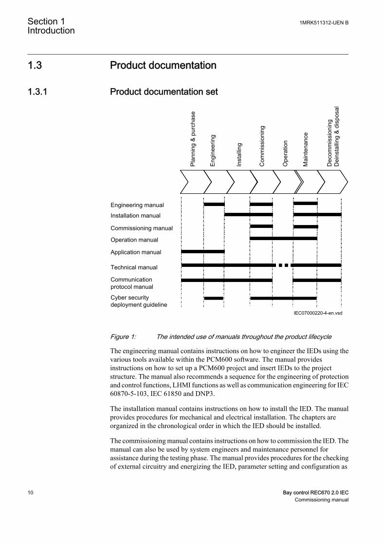
Figure 1: The intended use of manuals throughout the product lifecycle
The engineering manual contains instructions on how to engineer the IEDs using thevarious tools available within the PCM600 software. The manual providesinstructions on how to set up a PCM600 project and insert IEDs to the projectstructure. The manual also recommends a sequence for the engineering of protectionand control functions, LHMI functions as well as communication engineering for IEC60870-5-103, IEC 61850 and DNP3.
The installation manual contains instructions on how to install the IED. The manualprovides procedures for mechanical and electrical installation. The chapters areorganized in the chronological order in which the IED should be installed.
The commissioning manual contains instructions on how to commission the IED. Themanual can also be used by system engineers and maintenance personnel forassistance during the testing phase. The manual provides procedures for the checkingof external circuitry and energizing the IED, parameter setting and configuration as
Section 1 1MRK511312-UEN BIntroduction
10 Bay control REC670 2.0 IECCommissioning manual
well as verifying settings by secondary injection. The manual describes the process oftesting an IED in a substation which is not in service. The chapters are organized in thechronological order in which the IED should be commissioned. The relevantprocedures may be followed also during the service and maintenance activities.
The operation manual contains instructions on how to operate the IED once it has beencommissioned. The manual provides instructions for the monitoring, controlling andsetting of the IED. The manual also describes how to identify disturbances and how toview calculated and measured power grid data to determine the cause of a fault.
The application manual contains application descriptions and setting guidelinessorted per function. The manual can be used to find out when and for what purpose atypical protection function can be used. The manual can also provide assistance forcalculating settings.
The technical manual contains application and functionality descriptions and listsfunction blocks, logic diagrams, input and output signals, setting parameters andtechnical data, sorted per function. The manual can be used as a technical referenceduring the engineering phase, installation and commissioning phase, and duringnormal service.
The communication protocol manual describes the communication protocolssupported by the IED. The manual concentrates on the vendor-specificimplementations.
The point list manual describes the outlook and properties of the data points specificto the IED. The manual should be used in conjunction with the correspondingcommunication protocol manual.
The cyber security deployment guideline describes the process for handling cybersecurity when communicating with the IED. Certification, Authorization with rolebased access control, and product engineering for cyber security related events aredescribed and sorted by function. The guideline can be used as a technical referenceduring the engineering phase, installation and commissioning phase, and duringnormal service.
1.3.2 DokumentenänderungsverzeichnisDokument geändert / am Historie-/Mai 2016 Erste Übersetzung von 1MRK 511 312-UEN
Version -
1MRK511312-UEN B Section 1Introduction
Bay control REC670 2.0 IEC 11Commissioning manual
1.3.3 Related documentsDocuments related to REC670 Identify numberApplication manual 1MRK 511 310-UEN
Commissioning manual 1MRK 511 312-UEN
Product guide 1MRK 511 313-BEN
Technical manual 1MRK 511 311-UEN
Type test certificate 1MRK 511 313-TEN
670 series manuals Identify numberOperation manual 1MRK 500 118-UEN
Engineering manual 1MRK 511 308-UEN
Installation manual 1MRK 514 019-UEN
Communication protocol manual, IEC60870-5-103
1MRK 511 304-UEN
Communication protocol manual, IEC 61850Edition 1
1MRK 511 302-UEN
Communication protocol manual, IEC 61850Edition 2
1MRK 511 303-UEN
Communication protocol manual, LON 1MRK 511 305-UEN
Communication protocol manual, SPA 1MRK 511 306-UEN
Accessories guide 1MRK 514 012-BEN
Cyber security deployment guideline 1MRK 511 309-UEN
Connection and Installation components 1MRK 513 003-BEN
Test system, COMBITEST 1MRK 512 001-BEN
1.4 Document symbols and conventions
1.4.1 Symbols
The electrical warning icon indicates the presence of a hazard whichcould result in electrical shock.
The warning icon indicates the presence of a hazard which couldresult in personal injury.
The caution hot surface icon indicates important information orwarning about the temperature of product surfaces.
Section 1 1MRK511312-UEN BIntroduction
12 Bay control REC670 2.0 IECCommissioning manual
The caution icon indicates important information or warning relatedto the concept discussed in the text. It might indicate the presence ofa hazard which could result in corruption of software or damage toequipment or property.
The information icon alerts the reader of important facts andconditions.
The tip icon indicates advice on, for example, how to design yourproject or how to use a certain function.
Although warning hazards are related to personal injury, it is necessary to understandthat under certain operational conditions, operation of damaged equipment may resultin degraded process performance leading to personal injury or death. It is importantthat the user fully complies with all warning and cautionary notices.
1.4.2 Document conventions
• Abbreviations and acronyms in this manual are spelled out in the glossary. Theglossary also contains definitions of important terms.
• Push button navigation in the LHMI menu structure is presented by using thepush button icons.For example, to navigate between the options, use and .
• HMI menu paths are presented in bold.For example, select Main menu/Settings.
• LHMI messages are shown in Courier font.For example, to save the changes in non-volatile memory, select Yes and press
.• Parameter names are shown in italics.
For example, the function can be enabled and disabled with the Operation setting.• Each function block symbol shows the available input/output signal.
• the character ^ in front of an input/output signal name indicates that thesignal name may be customized using the PCM600 software.
• the character * after an input signal name indicates that the signal must beconnected to another function block in the application configuration toachieve a valid application configuration.
• Logic diagrams describe the signal logic inside the function block and arebordered by dashed lines.
1MRK511312-UEN B Section 1Introduction
Bay control REC670 2.0 IEC 13Commissioning manual

• Signals in frames with a shaded area on their right hand side representsetting parameter signals that are only settable via the PST or LHMI.
• If an internal signal path cannot be drawn with a continuous line, the suffix-int is added to the signal name to indicate where the signal starts andcontinues.
• Signal paths that extend beyond the logic diagram and continue in anotherdiagram have the suffix ”-cont.”
Illustrations are used as an example and might show other productsthan the one the manual describes. The example that is illustrated isstill valid.
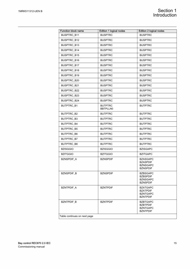
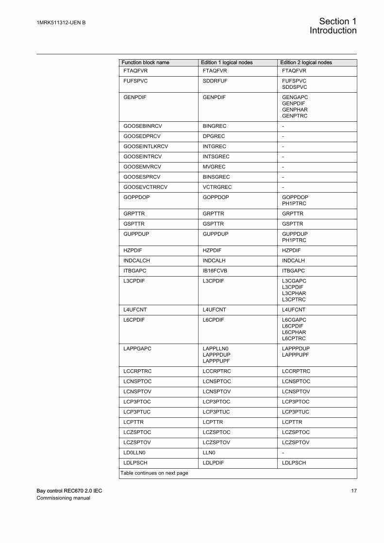
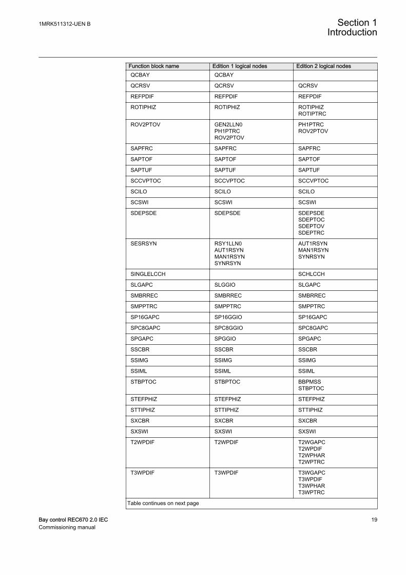
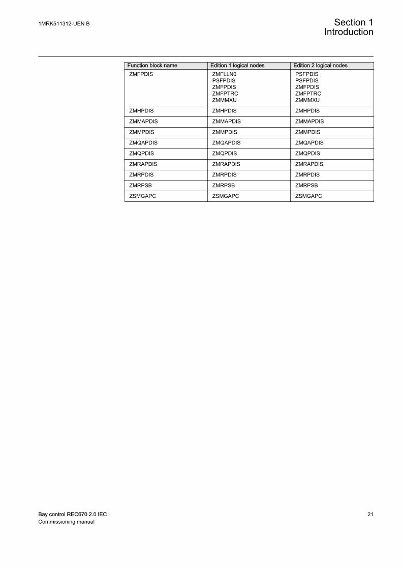
1.4.3 IEC 61850 edition 1 / edition 2 mappingTable 1: IEC 61850 edition 1 / edition 2 mapping
Function block name Edition 1 logical nodes Edition 2 logical nodesAEGPVOC AEGGAPC AEGPVOC
AGSAL AGSALSECLLN0
AGSAL
ALMCALH ALMCALH ALMCALH
ALTIM - ALTIM
ALTMS - ALTMS
ALTRK - ALTRK
BCZSPDIF BCZSPDIF BCZSPDIF
BCZTPDIF BCZTPDIF BCZTPDIF
BDCGAPC SWSGGIO BBCSWIBDCGAPC
BRCPTOC BRCPTOC BRCPTOC
BRPTOC BRPTOC BRPTOC
BTIGAPC B16IFCVI BTIGAPC
BUSPTRC_B1 BUSPTRCBBSPLLN0
BUSPTRC
BUSPTRC_B2 BUSPTRC BUSPTRC
BUSPTRC_B3 BUSPTRC BUSPTRC
BUSPTRC_B4 BUSPTRC BUSPTRC
BUSPTRC_B5 BUSPTRC BUSPTRC
BUSPTRC_B6 BUSPTRC BUSPTRC
BUSPTRC_B7 BUSPTRC BUSPTRC
BUSPTRC_B8 BUSPTRC BUSPTRC
BUSPTRC_B9 BUSPTRC BUSPTRC
BUSPTRC_B10 BUSPTRC BUSPTRC
Table continues on next page
Section 1 1MRK511312-UEN BIntroduction
14 Bay control REC670 2.0 IECCommissioning manual
Function block name Edition 1 logical nodes Edition 2 logical nodesBUSPTRC_B11 BUSPTRC BUSPTRC
BUSPTRC_B12 BUSPTRC BUSPTRC
BUSPTRC_B13 BUSPTRC BUSPTRC
BUSPTRC_B14 BUSPTRC BUSPTRC
BUSPTRC_B15 BUSPTRC BUSPTRC
BUSPTRC_B16 BUSPTRC BUSPTRC
BUSPTRC_B17 BUSPTRC BUSPTRC
BUSPTRC_B18 BUSPTRC BUSPTRC
BUSPTRC_B19 BUSPTRC BUSPTRC
BUSPTRC_B20 BUSPTRC BUSPTRC
BUSPTRC_B21 BUSPTRC BUSPTRC
BUSPTRC_B22 BUSPTRC BUSPTRC
BUSPTRC_B23 BUSPTRC BUSPTRC
BUSPTRC_B24 BUSPTRC BUSPTRC
BUTPTRC_B1 BUTPTRCBBTPLLN0
BUTPTRC
BUTPTRC_B2 BUTPTRC BUTPTRC
BUTPTRC_B3 BUTPTRC BUTPTRC
BUTPTRC_B4 BUTPTRC BUTPTRC
BUTPTRC_B5 BUTPTRC BUTPTRC
BUTPTRC_B6 BUTPTRC BUTPTRC
BUTPTRC_B7 BUTPTRC BUTPTRC
BUTPTRC_B8 BUTPTRC BUTPTRC
BZISGGIO BZISGGIO BZISGAPC
BZITGGIO BZITGGIO BZITGAPC
BZNSPDIF_A BZNSPDIF BZASGAPCBZASPDIFBZNSGAPCBZNSPDIF
BZNSPDIF_B BZNSPDIF BZBSGAPCBZBSPDIFBZNSGAPCBZNSPDIF
BZNTPDIF_A BZNTPDIF BZATGAPCBZATPDIFBZNTGAPCBZNTPDIF
BZNTPDIF_B BZNTPDIF BZBTGAPCBZBTPDIFBZNTGAPCBZNTPDIF
Table continues on next page
1MRK511312-UEN B Section 1Introduction
Bay control REC670 2.0 IEC 15Commissioning manual

Function block name Edition 1 logical nodes Edition 2 logical nodesCBPGAPC CBPLLN0
CBPMMXUCBPPTRCHOLPTOVHPH1PTOVPH3PTUCPH3PTOCRP3PDOP
CBPMMXUCBPPTRCHOLPTOVHPH1PTOVPH3PTOCPH3PTUCRP3PDOP
CCPDSC CCRPLD CCPDSC
CCRBRF CCRBRF CCRBRF
CCRWRBRF CCRWRBRF CCRWRBRF
CCSRBRF CCSRBRF CCSRBRF
CCSSPVC CCSRDIF CCSSPVC
CMMXU CMMXU CMMXU
CMSQI CMSQI CMSQI
COUVGAPC COUVLLN0COUVPTOVCOUVPTUV
COUVPTOVCOUVPTUV
CVGAPC GF2LLN0GF2MMXNGF2PHARGF2PTOVGF2PTUCGF2PTUVGF2PVOCPH1PTRC
GF2MMXNGF2PHARGF2PTOVGF2PTUCGF2PTUVGF2PVOCPH1PTRC
CVMMXN CVMMXN CVMMXN
D2PTOC D2LLN0D2PTOCPH1PTRC
D2PTOCPH1PTRC
DPGAPC DPGGIO DPGAPC
DRPRDRE DRPRDRE DRPRDRE
ECPSCH ECPSCH ECPSCH
ECRWPSCH ECRWPSCH ECRWPSCH
EF2PTOC EF2LLN0EF2PTRCEF2RDIRGEN2PHARPH1PTOC
EF2PTRCEF2RDIRGEN2PHARPH1PTOC
EF4PTOC EF4LLN0EF4PTRCEF4RDIRGEN4PHARPH1PTOC
EF4PTRCEF4RDIRGEN4PHARPH1PTOC
EFPIOC EFPIOC EFPIOC
EFRWPIOC EFRWPIOC EFRWPIOC
ETPMMTR ETPMMTR ETPMMTR
FDPSPDIS FDPSPDIS FDPSPDIS
FMPSPDIS FMPSPDIS FMPSPDIS
FRPSPDIS FPSRPDIS FPSRPDIS
Table continues on next page
Section 1 1MRK511312-UEN BIntroduction
16 Bay control REC670 2.0 IECCommissioning manual
Function block name Edition 1 logical nodes Edition 2 logical nodesFTAQFVR FTAQFVR FTAQFVR
FUFSPVC SDDRFUF FUFSPVCSDDSPVC
GENPDIF GENPDIF GENGAPCGENPDIFGENPHARGENPTRC
GOOSEBINRCV BINGREC -
GOOSEDPRCV DPGREC -
GOOSEINTLKRCV INTGREC -
GOOSEINTRCV INTSGREC -
GOOSEMVRCV MVGREC -
GOOSESPRCV BINSGREC -
GOOSEVCTRRCV VCTRGREC -
GOPPDOP GOPPDOP GOPPDOPPH1PTRC
GRPTTR GRPTTR GRPTTR
GSPTTR GSPTTR GSPTTR
GUPPDUP GUPPDUP GUPPDUPPH1PTRC
HZPDIF HZPDIF HZPDIF
INDCALCH INDCALH INDCALH
ITBGAPC IB16FCVB ITBGAPC
L3CPDIF L3CPDIF L3CGAPCL3CPDIFL3CPHARL3CPTRC
L4UFCNT L4UFCNT L4UFCNT
L6CPDIF L6CPDIF L6CGAPCL6CPDIFL6CPHARL6CPTRC
LAPPGAPC LAPPLLN0LAPPPDUPLAPPPUPF
LAPPPDUPLAPPPUPF
LCCRPTRC LCCRPTRC LCCRPTRC
LCNSPTOC LCNSPTOC LCNSPTOC
LCNSPTOV LCNSPTOV LCNSPTOV
LCP3PTOC LCP3PTOC LCP3PTOC
LCP3PTUC LCP3PTUC LCP3PTUC
LCPTTR LCPTTR LCPTTR
LCZSPTOC LCZSPTOC LCZSPTOC
LCZSPTOV LCZSPTOV LCZSPTOV
LD0LLN0 LLN0 -
LDLPSCH LDLPDIF LDLPSCH
Table continues on next page
1MRK511312-UEN B Section 1Introduction
Bay control REC670 2.0 IEC 17Commissioning manual

Function block name Edition 1 logical nodes Edition 2 logical nodesLDRGFC STSGGIO LDRGFC
LEXPDIS LEXPDIS LEXPDISLEXPTRC
LFPTTR LFPTTR LFPTTR
LMBRFLO LMBRFLO LMBRFLO
LOVPTUV LOVPTUV LOVPTUV
LPHD LPHD
LPTTR LPTTR LPTTR
LT3CPDIF LT3CPDIF LT3CGAPCLT3CPDIFLT3CPHARLT3CPTRC
LT6CPDIF LT6CPDIF LT6CGAPCLT6CPDIFLT6CPHARLT6CPTRC
MVGAPC MVGGIO MVGAPC
NS2PTOC NS2LLN0NS2PTOCNS2PTRC
NS2PTOCNS2PTRC
NS4PTOC EF4LLN0EF4PTRCEF4RDIRGEN4PHARPH1PTOC
EF4PTRCEF4RDIRPH1PTOC
O2RWPTOV GEN2LLN0O2RWPTOVPH1PTRC
O2RWPTOVPH1PTRC
OC4PTOC OC4LLN0GEN4PHARPH3PTOCPH3PTRC
GEN4PHARPH3PTOCPH3PTRC
OEXPVPH OEXPVPH OEXPVPH
OOSPPAM OOSPPAM OOSPPAMOOSPTRC
OV2PTOV GEN2LLN0OV2PTOVPH1PTRC
OV2PTOVPH1PTRC
PAPGAPC PAPGAPC PAPGAPC
PCFCNT PCGGIO PCFCNT
PH4SPTOC GEN4PHAROCNDLLN0PH1BPTOCPH1PTRC
GEN4PHARPH1BPTOCPH1PTRC
PHPIOC PHPIOC PHPIOC
PRPSTATUS RCHLCCH RCHLCCHSCHLCCH
PSLPSCH ZMRPSL PSLPSCH
PSPPPAM PSPPPAM PSPPPAMPSPPTRC
Table continues on next page
Section 1 1MRK511312-UEN BIntroduction
18 Bay control REC670 2.0 IECCommissioning manual
Function block name Edition 1 logical nodes Edition 2 logical nodesQCBAY QCBAY
QCRSV QCRSV QCRSV
REFPDIF REFPDIF REFPDIF
ROTIPHIZ ROTIPHIZ ROTIPHIZROTIPTRC
ROV2PTOV GEN2LLN0PH1PTRCROV2PTOV
PH1PTRCROV2PTOV
SAPFRC SAPFRC SAPFRC
SAPTOF SAPTOF SAPTOF
SAPTUF SAPTUF SAPTUF
SCCVPTOC SCCVPTOC SCCVPTOC
SCILO SCILO SCILO
SCSWI SCSWI SCSWI
SDEPSDE SDEPSDE SDEPSDESDEPTOCSDEPTOVSDEPTRC
SESRSYN RSY1LLN0AUT1RSYNMAN1RSYNSYNRSYN
AUT1RSYNMAN1RSYNSYNRSYN
SINGLELCCH SCHLCCH
SLGAPC SLGGIO SLGAPC
SMBRREC SMBRREC SMBRREC
SMPPTRC SMPPTRC SMPPTRC
SP16GAPC SP16GGIO SP16GAPC
SPC8GAPC SPC8GGIO SPC8GAPC
SPGAPC SPGGIO SPGAPC
SSCBR SSCBR SSCBR
SSIMG SSIMG SSIMG
SSIML SSIML SSIML
STBPTOC STBPTOC BBPMSSSTBPTOC
STEFPHIZ STEFPHIZ STEFPHIZ
STTIPHIZ STTIPHIZ STTIPHIZ
SXCBR SXCBR SXCBR
SXSWI SXSWI SXSWI
T2WPDIF T2WPDIF T2WGAPCT2WPDIFT2WPHART2WPTRC
T3WPDIF T3WPDIF T3WGAPCT3WPDIFT3WPHART3WPTRC
Table continues on next page
1MRK511312-UEN B Section 1Introduction
Bay control REC670 2.0 IEC 19Commissioning manual

Function block name Edition 1 logical nodes Edition 2 logical nodesTCLYLTC TCLYLTC TCLYLTC
TCSLTC
TCMYLTC TCMYLTC TCMYLTC
TEIGAPC TEIGGIO TEIGAPCTEIGGIO
TEILGAPC TEILGGIO TEILGAPC
TMAGAPC TMAGGIO TMAGAPC
TPPIOC TPPIOC TPPIOC
TR1ATCC TR1ATCC TR1ATCC
TR8ATCC TR8ATCC TR8ATCC
TRPTTR TRPTTR TRPTTR
U2RWPTUV GEN2LLN0PH1PTRCU2RWPTUV
PH1PTRCU2RWPTUV
UV2PTUV GEN2LLN0PH1PTRCUV2PTUV
PH1PTRCUV2PTUV
VDCPTOV VDCPTOV VDCPTOV
VDSPVC VDRFUF VDSPVC
VMMXU VMMXU VMMXU
VMSQI VMSQI VMSQI
VNMMXU VNMMXU VNMMXU
VRPVOC VRLLN0PH1PTRCPH1PTUVVRPVOC
PH1PTRCPH1PTUVVRPVOC
VSGAPC VSGGIO VSGAPC
WRNCALH WRNCALH WRNCALH
ZC1PPSCH ZPCPSCH ZPCPSCH
ZC1WPSCH ZPCWPSCH ZPCWPSCH
ZCLCPSCH ZCLCPLAL ZCLCPSCH
ZCPSCH ZCPSCH ZCPSCH
ZCRWPSCH ZCRWPSCH ZCRWPSCH
ZCVPSOF ZCVPSOF ZCVPSOF
ZGVPDIS ZGVLLN0PH1PTRCZGVPDISZGVPTUV
PH1PTRCZGVPDISZGVPTUV
ZMCAPDIS ZMCAPDIS ZMCAPDIS
ZMCPDIS ZMCPDIS ZMCPDIS
ZMFCPDIS ZMFCLLN0PSFPDISZMFPDISZMFPTRCZMMMXU
PSFPDISZMFPDISZMFPTRCZMMMXU
Table continues on next page
Section 1 1MRK511312-UEN BIntroduction
20 Bay control REC670 2.0 IECCommissioning manual
Function block name Edition 1 logical nodes Edition 2 logical nodesZMFPDIS ZMFLLN0
PSFPDISZMFPDISZMFPTRCZMMMXU
PSFPDISPSFPDISZMFPDISZMFPTRCZMMMXU
ZMHPDIS ZMHPDIS ZMHPDIS
ZMMAPDIS ZMMAPDIS ZMMAPDIS
ZMMPDIS ZMMPDIS ZMMPDIS
ZMQAPDIS ZMQAPDIS ZMQAPDIS
ZMQPDIS ZMQPDIS ZMQPDIS
ZMRAPDIS ZMRAPDIS ZMRAPDIS
ZMRPDIS ZMRPDIS ZMRPDIS
ZMRPSB ZMRPSB ZMRPSB
ZSMGAPC ZSMGAPC ZSMGAPC
1MRK511312-UEN B Section 1Introduction
Bay control REC670 2.0 IEC 21Commissioning manual

22
Section 2 Safety information
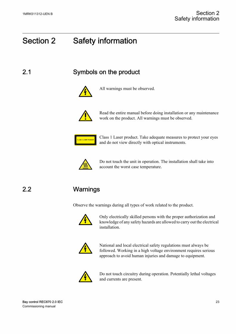
2.1 Symbols on the product
All warnings must be observed.
Read the entire manual before doing installation or any maintenancework on the product. All warnings must be observed.
Class 1 Laser product. Take adequate measures to protect your eyesand do not view directly with optical instruments.
Do not touch the unit in operation. The installation shall take intoaccount the worst case temperature.
2.2 Warnings
Observe the warnings during all types of work related to the product.
Only electrically skilled persons with the proper authorization andknowledge of any safety hazards are allowed to carry out the electricalinstallation.
National and local electrical safety regulations must always befollowed. Working in a high voltage environment requires seriousapproach to avoid human injuries and damage to equipment.
Do not touch circuitry during operation. Potentially lethal voltagesand currents are present.
1MRK511312-UEN B Section 2Safety information
Bay control REC670 2.0 IEC 23Commissioning manual
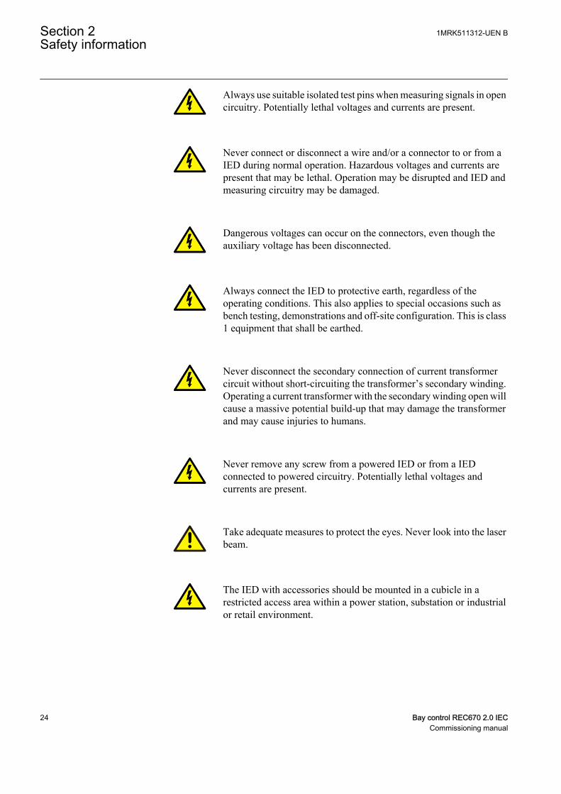
Always use suitable isolated test pins when measuring signals in opencircuitry. Potentially lethal voltages and currents are present.
Never connect or disconnect a wire and/or a connector to or from aIED during normal operation. Hazardous voltages and currents arepresent that may be lethal. Operation may be disrupted and IED andmeasuring circuitry may be damaged.
Dangerous voltages can occur on the connectors, even though theauxiliary voltage has been disconnected.
Always connect the IED to protective earth, regardless of theoperating conditions. This also applies to special occasions such asbench testing, demonstrations and off-site configuration. This is class1 equipment that shall be earthed.
Never disconnect the secondary connection of current transformercircuit without short-circuiting the transformer’s secondary winding.Operating a current transformer with the secondary winding open willcause a massive potential build-up that may damage the transformerand may cause injuries to humans.
Never remove any screw from a powered IED or from a IEDconnected to powered circuitry. Potentially lethal voltages andcurrents are present.
Take adequate measures to protect the eyes. Never look into the laserbeam.
The IED with accessories should be mounted in a cubicle in arestricted access area within a power station, substation or industrialor retail environment.
Section 2 1MRK511312-UEN BSafety information
24 Bay control REC670 2.0 IECCommissioning manual
2.3 Caution signs
Whenever changes are made in the IED, measures should be taken toavoid inadvertent tripping.
The IED contains components which are sensitive to electrostaticdischarge. ESD precautions shall always be observed prior totouching components.
Always transport PCBs (modules) using certified conductive bags.
Do not connect live wires to the IED. Internal circuitry may bedamaged
Always use a conductive wrist strap connected to protective earthwhen replacing modules. Electrostatic discharge (ESD) may damagethe module and IED circuitry.
Take care to avoid electrical shock during installation andcommissioning.
Changing the active setting group will inevitably change the IEDsoperation. Be careful and check regulations before making thechange.
2.4 Note signs
Observe the maximum allowed continuous current for the differentcurrent transformer inputs of the IED. See technical data.
1MRK511312-UEN B Section 2Safety information
Bay control REC670 2.0 IEC 25Commissioning manual

26
Section 3 Available functions
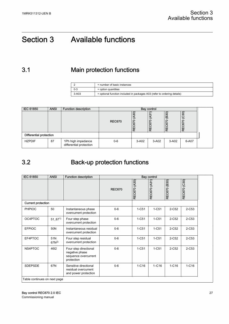
3.1 Main protection functions
2 = number of basic instances0-3 = option quantities3-A03 = optional function included in packages A03 (refer to ordering details)
IEC 61850 ANSI Function description Bay control
REC670
REC
670
(A30
)
REC
670
(A31
)
REC
670
(B30
)
REC
670
(C30
)
Differential protection
HZPDIF 87 1Ph high impedancedifferential protection
0-6 3-A02 3-A02 3-A02 6-A07
3.2 Back-up protection functions
IEC 61850 ANSI Function description Bay control
REC670
REC
670
(A30
)
REC
670
(A31
)
REC
670
(B30
)
REC
670
(C30
)
Current protection
PHPIOC 50 Instantaneous phaseovercurrent protection
0-6 1-C51 1-C51 2-C52 2-C53
OC4PTOC 51_671) Four step phaseovercurrent protection
0-6 1-C51 1-C51 2-C52 2-C53
EFPIOC 50N Instantaneous residualovercurrent protection
0-6 1-C51 1-C51 2-C52 2-C53
EF4PTOC 51N67N2)
Four step residualovercurrent protection
0-6 1-C51 1-C51 2-C52 2-C53
NS4PTOC 46I2 Four step directionalnegative phasesequence overcurrentprotection
0-6 1-C51 1-C51 2-C52 2-C53
SDEPSDE 67N Sensitive directionalresidual overcurrentand power protection
0-6 1-C16 1–C16 1-C16 1-C16
Table continues on next page
1MRK511312-UEN B Section 3Available functions
Bay control REC670 2.0 IEC 27Commissioning manual
IEC 61850 ANSI Function description Bay control
REC670
REC
670
(A30
)
REC
670
(A31
)
REC
670
(B30
)
REC
670
(C30
)
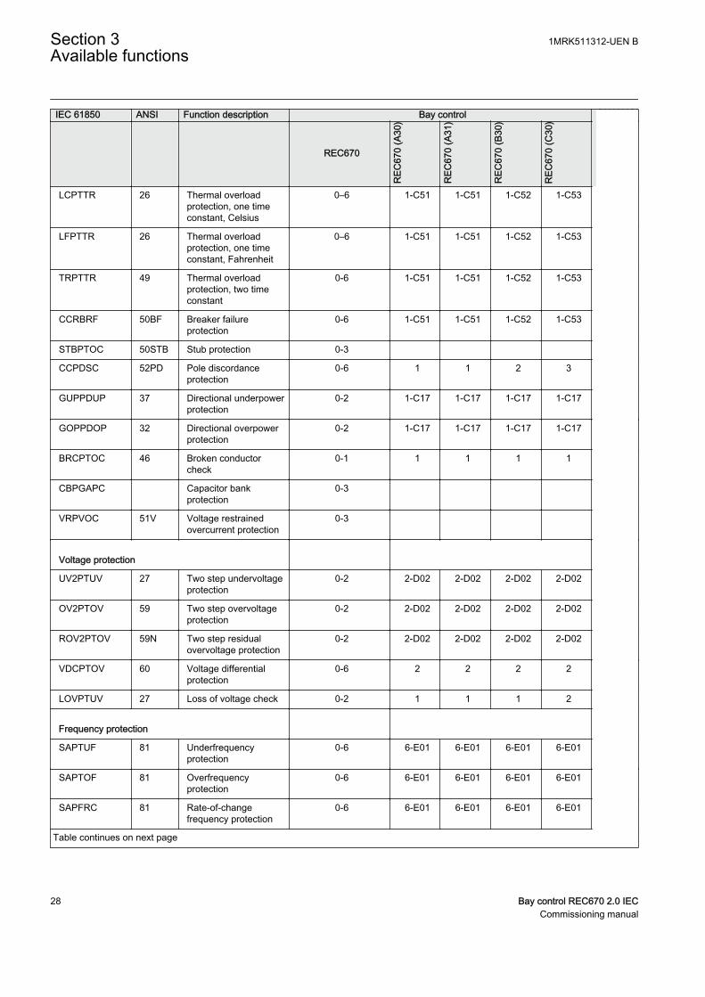
LCPTTR 26 Thermal overloadprotection, one timeconstant, Celsius
0–6 1-C51 1-C51 1-C52 1-C53
LFPTTR 26 Thermal overloadprotection, one timeconstant, Fahrenheit
0–6 1-C51 1-C51 1-C52 1-C53
TRPTTR 49 Thermal overloadprotection, two timeconstant
0-6 1-C51 1-C51 1-C52 1-C53
CCRBRF 50BF Breaker failureprotection
0-6 1-C51 1-C51 1-C52 1-C53
STBPTOC 50STB Stub protection 0-3
CCPDSC 52PD Pole discordanceprotection
0-6 1 1 2 3
GUPPDUP 37 Directional underpowerprotection
0-2 1-C17 1-C17 1-C17 1-C17
GOPPDOP 32 Directional overpowerprotection
0-2 1-C17 1-C17 1-C17 1-C17
BRCPTOC 46 Broken conductorcheck
0-1 1 1 1 1
CBPGAPC Capacitor bankprotection
0-3
VRPVOC 51V Voltage restrainedovercurrent protection
0-3
Voltage protection
UV2PTUV 27 Two step undervoltageprotection
0-2 2-D02 2-D02 2-D02 2-D02
OV2PTOV 59 Two step overvoltageprotection
0-2 2-D02 2-D02 2-D02 2-D02
ROV2PTOV 59N Two step residualovervoltage protection
0-2 2-D02 2-D02 2-D02 2-D02
VDCPTOV 60 Voltage differentialprotection
0-6 2 2 2 2
LOVPTUV 27 Loss of voltage check 0-2 1 1 1 2
Frequency protection
SAPTUF 81 Underfrequencyprotection
0-6 6-E01 6-E01 6-E01 6-E01
SAPTOF 81 Overfrequencyprotection
0-6 6-E01 6-E01 6-E01 6-E01
SAPFRC 81 Rate-of-changefrequency protection
0-6 6-E01 6-E01 6-E01 6-E01
Table continues on next page
Section 3 1MRK511312-UEN BAvailable functions
28 Bay control REC670 2.0 IECCommissioning manual

IEC 61850 ANSI Function description Bay control
REC670
REC
670
(A30
)
REC
670
(A31
)
REC
670
(B30
)
REC
670
(C30
)
FTAQFVR 81A Frequency timeaccumulationprotection
0-12
Multipurpose protection
CVGAPC General current andvoltage protection
0-9 4-F01 4-F01 4-F01 4-F01
General calculation
SMAIHPAC Multipurpose filter 0-6
1) 67 requires voltage2) 67N requires voltage
3.3 Control and monitoring functions
IEC 61850 ANSI Function description Bay control
REC670
REC
670
(A30
)
REC
670
(A31
)
REC
670
(B30
)
REC
670
(C30
)
Control
SESRSYN 25 Synchrocheck, energizing checkand synchronizing
0-6, 0-2 1 1 2 3
SMBRREC 79 Autorecloser 0-6, 0-4 1-H04 1-H04 2-H05 3-H06
APC8 3 Apparatus control for single bay,max 8 apparatuses (1CB) incl.interlocking
1 1 1
APC15 3 Apparatus control for single bay,max 15 apparatuses (2CBs) incl.interlocking
1 1
APC30 3 Apparatus control for up to 6 bays,max 30 apparatuses (6CBs) incl.interlocking
1 1
QCBAY Apparatus control 1+5/APC30 1 1 1 1+5/APC3
0
LOCREM Handling of LRswitch positions 1+5/APC30 1 1 1 1+5/APC3
0
LOCREMCTRL LHMI control of PSTO 1+5/APC30 1 1 1 1+5/APC3
0
Table continues on next page
1MRK511312-UEN B Section 3Available functions
Bay control REC670 2.0 IEC 29Commissioning manual
IEC 61850 ANSI Function description Bay control
REC670
REC
670
(A30
)
REC
670
(A31
)
REC
670
(B30
)
REC
670
(C30
)
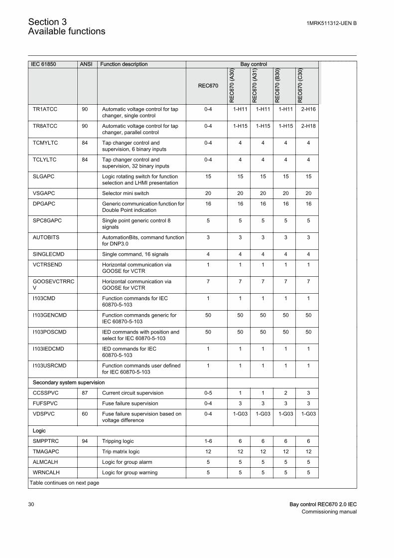
TR1ATCC 90 Automatic voltage control for tapchanger, single control
0-4 1-H11 1-H11 1-H11 2-H16
TR8ATCC 90 Automatic voltage control for tapchanger, parallel control
0-4 1-H15 1-H15 1-H15 2-H18
TCMYLTC 84 Tap changer control andsupervision, 6 binary inputs
0-4 4 4 4 4
TCLYLTC 84 Tap changer control andsupervision, 32 binary inputs
0-4 4 4 4 4
SLGAPC Logic rotating switch for functionselection and LHMI presentation
15 15 15 15 15
VSGAPC Selector mini switch 20 20 20 20 20
DPGAPC Generic communication function forDouble Point indication
16 16 16 16 16
SPC8GAPC Single point generic control 8signals
5 5 5 5 5
AUTOBITS AutomationBits, command functionfor DNP3.0
3 3 3 3 3
SINGLECMD Single command, 16 signals 4 4 4 4 4
VCTRSEND Horizontal communication viaGOOSE for VCTR
1 1 1 1 1
GOOSEVCTRRCV
Horizontal communication viaGOOSE for VCTR
7 7 7 7 7
I103CMD Function commands for IEC60870-5-103
1 1 1 1 1
I103GENCMD Function commands generic forIEC 60870-5-103
50 50 50 50 50
I103POSCMD IED commands with position andselect for IEC 60870-5-103
50 50 50 50 50
I103IEDCMD IED commands for IEC60870-5-103
1 1 1 1 1
I103USRCMD Function commands user definedfor IEC 60870-5-103
1 1 1 1 1
Secondary system supervision
CCSSPVC 87 Current circuit supervision 0-5 1 1 2 3
FUFSPVC Fuse failure supervision 0-4 3 3 3 3
VDSPVC 60 Fuse failure supervision based onvoltage difference
0-4 1-G03 1-G03 1-G03 1-G03
Logic
SMPPTRC 94 Tripping logic 1-6 6 6 6 6
TMAGAPC Trip matrix logic 12 12 12 12 12
ALMCALH Logic for group alarm 5 5 5 5 5
WRNCALH Logic for group warning 5 5 5 5 5
Table continues on next page
Section 3 1MRK511312-UEN BAvailable functions
30 Bay control REC670 2.0 IECCommissioning manual

IEC 61850 ANSI Function description Bay control
REC670
REC
670
(A30
)
REC
670
(A31
)
REC
670
(B30
)
REC
670
(C30
)
INDCALH Logic for group indication 5 5 5 5 5
AND, OR, INV,PULSETIMER,GATE,TIMERSET, XOR,LLD,SRMEMORY,RSMEMORY
Configurable logic blocks 40-280 40-280
40-280
40-280
40-280
ANDQT, ORQT,INVERTERQT,XORQT,SRMEMORYQT,RSMEMORYQT,TIMERSETQT,PULSETIMERQT, INVALIDQT,INDCOMBSPQT,INDEXTSPQT
Configurable logic blocks Q/T 0-1
SLGAPC,VSGAPC, AND,OR,PULSETIMER,GATE,TIMERSET, XOR,LLD,SRMEMORY,INV
Extension logic package 0-1
FXDSIGN Fixed signal function block 1 1 1 1 1
B16I Boolean 16 to Integer conversion 18 18 18 18 18
BTIGAPC Boolean 16 to Integer conversionwith Logic Node representation
16 16 16 16 16
IB16 Integer to Boolean 16 conversion 18 18 18 18 18
ITBGAPC Integer to Boolean 16 conversionwith Logic Node representation
16 16 16 16 16
TEIGAPC Elapsed time integrator with limittransgression and overflowsupervision
12 12 12 12 12
Monitoring
CVMMXN,CMMXU,VMMXU, CMSQI,VMSQI,VNMMXU
Measurements 6 6 6 6 6
AISVBAS Function block for service valuepresentation of secondary analoginputs
1 1 1 1 1
EVENT Event function 20 20 20 20 20
Table continues on next page
1MRK511312-UEN B Section 3Available functions
Bay control REC670 2.0 IEC 31Commissioning manual
IEC 61850 ANSI Function description Bay control
REC670
REC
670
(A30
)
REC
670
(A31
)
REC
670
(B30
)
REC
670
(C30
)
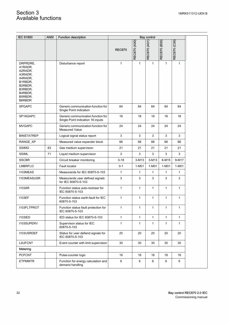
DRPRDRE,A1RADR,A2RADR,A3RADR,A4RADR,B1RBDR,B2RBDR,B3RBDR,B4RBDR,B5RBDR,B6RBDR
Disturbance report 1 1 1 1 1
SPGAPC Generic communication function forSingle Point indication
64 64 64 64 64
SP16GAPC Generic communication function forSingle Point indication 16 inputs
16 16 16 16 16
MVGAPC Generic communication function forMeasured Value
24 24 24 24 24
BINSTATREP Logical signal status report 3 3 3 3 3
RANGE_XP Measured value expander block 66 66 66 66 66
SSIMG 63 Gas medium supervision 21 21 21 21 21
SSIML 71 Liquid medium supervision 3 3 3 3 3
SSCBR Circuit breaker monitoring 0-18 3-M13 3-M13 6-M15 9-M17
LMBRFLO Fault locator 0-1 1-M01 1-M01 1-M01 1-M01
I103MEAS Measurands for IEC 60870-5-103 1 1 1 1 1
I103MEASUSR Measurands user defined signalsfor IEC 60870-5-103
3 3 3 3 3
I103AR Function status auto-recloser forIEC 60870-5-103
1 1 1 1 1
I103EF Function status earth-fault for IEC60870-5-103
1 1 1 1 1
I103FLTPROT Function status fault protection forIEC 60870-5-103
1 1 1 1 1
I103IED IED status for IEC 60870-5-103 1 1 1 1 1
I103SUPERV Supervison status for IEC60870-5-103
1 1 1 1 1
I103USRDEF Status for user defiend signals forIEC 60870-5-103
20 20 20 20 20
L4UFCNT Event counter with limit supervision 30 30 30 30 30
Metering
PCFCNT Pulse-counter logic 16 16 16 16 16
ETPMMTR Function for energy calculation anddemand handling
6 6 6 6 6
Section 3 1MRK511312-UEN BAvailable functions
32 Bay control REC670 2.0 IECCommissioning manual

3.4 Communication
IEC 61850 ANSI Function description Bay control
REC670
REC
670
(A30
)
REC
670
(A31
REC
670
(B30
)
REC
670
(C30
)
Station communication
LONSPA, SPA SPA communicationprotocol
1 1 1 1 1
ADE LON communicationprotocol
1 1 1 1 1
HORZCOMM Network variables viaLON
1 1 1 1 1
PROTOCOL Operation selectionbetween SPA and IEC60870-5-103 for SLM
1 1 1 1 1
RS485PROT Operation selection forRS485
1 1 1 1 1
RS485GEN RS485 1 1 1 1 1
DNPGEN DNP3.0communication generalprotocol
1 1 1 1 1
DNPGENTCP DNP3.0communication generalTCP protocol
1 1 1 1 1
CHSERRS485 DNP3.0 for EIA-485communicationprotocol
1 1 1 1 1
CH1TCP,CH2TCP,CH3TCP,CH4TCP
DNP3.0 for TCP/IPcommunicationprotocol
1 1 1 1 1
CHSEROPT DNP3.0 for TCP/IP andEIA-485communicationprotocol
1 1 1 1 1
MST1TCP,MST2TCP,MST3TCP,MST4TCP
DNP3.0 for serialcommunicationprotocol
1 1 1 1 1
DNPFREC DNP3.0 fault recordsfor TCP/IP and EIA-485communicationprotocol
1 1 1 1 1
IEC61850-8-1 Parameter settingfunction for IEC 61850
1 1 1 1 1
GOOSEINTLKRCV
Horizontalcommunication viaGOOSE for interlocking
59 59 59 59 59
GOOSEBINRCV Goose binary receive 16 16 16 16 16
Table continues on next page
1MRK511312-UEN B Section 3Available functions
Bay control REC670 2.0 IEC 33Commissioning manual
IEC 61850 ANSI Function description Bay control
REC670
REC
670
(A30
)
REC
670
(A31
REC
670
(B30
)
REC
670
(C30
)
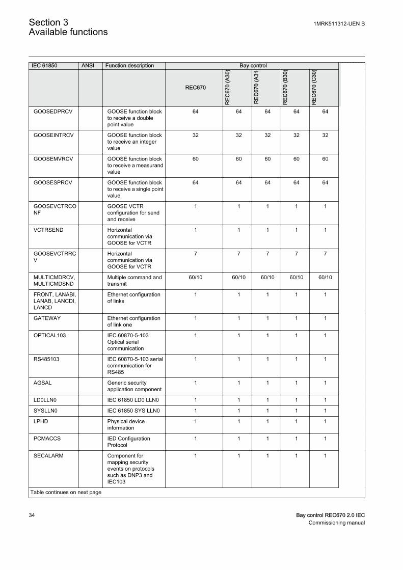
GOOSEDPRCV GOOSE function blockto receive a doublepoint value
64 64 64 64 64
GOOSEINTRCV GOOSE function blockto receive an integervalue
32 32 32 32 32
GOOSEMVRCV GOOSE function blockto receive a measurandvalue
60 60 60 60 60
GOOSESPRCV GOOSE function blockto receive a single pointvalue
64 64 64 64 64
GOOSEVCTRCONF
GOOSE VCTRconfiguration for sendand receive
1 1 1 1 1
VCTRSEND Horizontalcommunication viaGOOSE for VCTR
1 1 1 1 1
GOOSEVCTRRCV
Horizontalcommunication viaGOOSE for VCTR
7 7 7 7 7
MULTICMDRCV,MULTICMDSND
Multiple command andtransmit
60/10 60/10 60/10 60/10 60/10
FRONT, LANABI,LANAB, LANCDI,LANCD
Ethernet configurationof links
1 1 1 1 1
GATEWAY Ethernet configurationof link one
1 1 1 1 1
OPTICAL103 IEC 60870-5-103Optical serialcommunication
1 1 1 1 1
RS485103 IEC 60870-5-103 serialcommunication forRS485
1 1 1 1 1
AGSAL Generic securityapplication component
1 1 1 1 1
LD0LLN0 IEC 61850 LD0 LLN0 1 1 1 1 1
SYSLLN0 IEC 61850 SYS LLN0 1 1 1 1 1
LPHD Physical deviceinformation
1 1 1 1 1
PCMACCS IED ConfigurationProtocol
1 1 1 1 1
SECALARM Component formapping securityevents on protocolssuch as DNP3 andIEC103
1 1 1 1 1
Table continues on next page
Section 3 1MRK511312-UEN BAvailable functions
34 Bay control REC670 2.0 IECCommissioning manual
IEC 61850 ANSI Function description Bay control
REC670
REC
670
(A30
)
REC
670
(A31
REC
670
(B30
)
REC
670
(C30
)
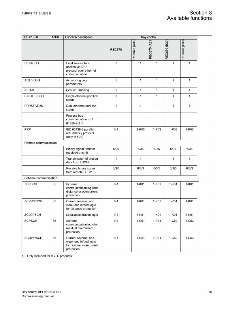
FSTACCS Field service toolaccess via SPAprotocol over ethernetcommunication
1 1 1 1 1
ACTIVLOG Activity loggingparameters
1 1 1 1 1
ALTRK Service Tracking 1 1 1 1 1
SINGLELCCH Single ethernet port linkstatus
1 1 1 1 1
PRPSTATUS Dual ethernet port linkstatus
1 1 1 1 1
Process buscommunication IEC61850-9-2 1)
PRP IEC 62439-3 parallelredundancy protocol(only in F00)
0-1 1-P03 1-P03 1-P03 1-P03
Remote communication
Binary signal transferreceive/transmit
6/36 6/36 6/36 6/36 6/36
Transmission of analogdata from LDCM
1 1 1 1 1
Receive binary statusfrom remote LDCM
6/3/3 6/3/3 6/3/3 6/3/3 6/3/3
Scheme communication
ZCPSCH 85 Schemecommunication logic fordistance or overcurrentprotection
0-1 1-K01 1-K01 1-K01 1-K01
ZCRWPSCH 85 Current reversal andweak-end infeed logicfor distance protection
0-1 1-K01 1-K01 1-K01 1-K01
ZCLCPSCH Local acceleration logic 0-1 1-K01 1-K01 1-K01 1-K01
ECPSCH 85 Schemecommunication logic forresidual overcurrentprotection
0-1 1-C51 1-C51 1-C52 1-C53
ECRWPSCH 85 Current reversal andweak-end infeed logicfor residual overcurrentprotection
0-1 1-C51 1-C51 1-C52 1-C53
1) Only included for 9-2LE products
1MRK511312-UEN B Section 3Available functions
Bay control REC670 2.0 IEC 35Commissioning manual

3.5 Basic IED functions
Table 2: Basic IED functions
IEC 61850 or functionname
Description
INTERRSIG Self supervision with internal event list
SELFSUPEVLST Self supervision with internal event list
TIMESYNCHGEN Time synchronization module
SYNCHBIN,SYNCHCAN,SYNCHCMPPS,SYNCHLON,SYNCHPPH,SYNCHPPS,SYNCHSNTP,SYNCHSPA,SYNCHCMPPS
Time synchronization
TIMEZONE Time synchronization
DSTBEGIN,DSTENABLE, DSTEND
GPS time synchronization module
IRIG-B Time synchronization
SETGRPS Number of setting groups
ACTVGRP Parameter setting groups
TESTMODE Test mode functionality
CHNGLCK Change lock function
SMBI Signal matrix for binary inputs
SMBO Signal matrix for binary outputs
SMMI Signal matrix for mA inputs
SMAI1 - SMAI20 Signal matrix for analog inputs
3PHSUM Summation block 3 phase
ATHSTAT Authority status
ATHCHCK Authority check
AUTHMAN Authority management
FTPACCS FTP access with password
SPACOMMMAP SPA communication mapping
SPATD Date and time via SPA protocol
DOSFRNT Denial of service, frame rate control for front port
DOSLANAB Denial of service, frame rate control for OEM port AB
DOSLANCD Denial of service, frame rate control for OEM port CD
DOSSCKT Denial of service, socket flow control
GBASVAL Global base values for settings
PRIMVAL Primary system values
ALTMS Time master supervision
ALTIM Time management
Table continues on next page
Section 3 1MRK511312-UEN BAvailable functions
36 Bay control REC670 2.0 IECCommissioning manual

IEC 61850 or functionname
Description
ALTRK Service tracking
ACTIVLOG Activity logging parameters
FSTACCS Field service tool access via SPA protocol over ethernet communication
PCMACCS IED Configuration Protocol
SECALARM Component for mapping security events on protocols such as DNP3 and IEC103
DNPGEN DNP3.0 communication general protocol
DNPGENTCP DNP3.0 communication general TCP protocol
CHSEROPT DNP3.0 for TCP/IP and EIA-485 communication protocol
MSTSER DNP3.0 for serial communication protocol
OPTICAL103 IEC 60870-5-103 Optical serial communication
RS485103 IEC 60870-5-103 serial communication for RS485
IEC61850-8-1 Parameter setting function for IEC 61850
HORZCOMM Network variables via LON
LONSPA SPA communication protocol
LEDGEN General LED indication part for LHMI
1MRK511312-UEN B Section 3Available functions
Bay control REC670 2.0 IEC 37Commissioning manual

38

Section 4 Starting up
4.1 Factory and site acceptance testing
Testing the proper IED operation is carried out at different occasions, for example:
• Acceptance testing• Commissioning testing• Maintenance testing
This manual describes the workflow and the steps to carry out the commissioningtesting.
Factory acceptance testing (FAT) is typically done to verify that the IED and itscorresponding configuration meet the requirements of the utility or industry. This testis the most complex and in depth, as it is done to familiarize the user with a newproduct or to verify a new configuration. The complexity of this testing depends onseveral factors, such as:
• New IED type• New configuration• Modified configuration
Site acceptance testing (SAT or commissioning testing) is typically done to verify thatthe installed IED is correctly set and connected to the power system. SAT requires thatthe acceptance testing has been performed and that the application configuration isverified.
Maintenance testing is a periodic verification that the IED is healthy and has correctsettings, depending on changes in the power system. There are also other types ofmaintenance testing.
4.2 Commissioning checklist
Before starting up commissioning at site, check that the following items are available.
• Single line diagram• Protection block diagram• Circuit diagram• Setting list and configuration• RJ-45 Ethernet cable (CAT 5)• Three-phase test kit or other test equipment depending on the complexity of the
configuration and functions to be tested.
1MRK511312-UEN B Section 4Starting up
Bay control REC670 2.0 IEC 39Commissioning manual
• PC with PCM600 installed along with the connectivity packages correspondingto the IEDs to be tested.
• Administration rights on the PC, to set up IP addresses• Product documentation (engineering manual, installation manual,
commissioning manual, operation manual, technical manual and communicationprotocol manual)
4.3 Checking the power supply
Do not insert anything else to the female connector but thecorresponding male connector. Inserting anything else (such as ameasurement probe) may damage the female connector and prevent aproper electrical contact between the printed circuit board and theexternal wiring connected to the screw terminal block.
Check that the auxiliary supply voltage remains within the permissible input voltagerange under all operating conditions. Check that the polarity is correct beforeenergizing the IED.
4.4 Energizing the IED
4.4.1 Checking the IED operation
Check all connections to external circuitry to ensure correct installation, beforeenergizing the IED and carrying out the commissioning procedures.
Energize the power supply of the IED to start it up. Keep the DC power supply on untilthe Root menu or the selected default screen is shown on the HMI before interruptingthe DC power supply again. The energization could be done in a number of ways, fromenergizing a whole cubicle with many IEDs to energizing each single IED one by one.
If HW (i.e. I/O and/or communication boards etc.) have been changed (i.e. removed,replaced, or added), the user should re-configure the IED by navigating in the localHMI menu to: Main menu/Configuration/Reconfigure HW modules to activatethe changed hardware modules in order to enable the self-supervision function todetect possible hardware errors.
Check also the self-supervision function in Main menu/Diagnostics/IED status/General menu in local HMI to verify that the IED operates properly.
Set the IED time if no time synchronization source is configured.
To ensure that the IED is according to the delivery and ordering specificationsdocuments delivered together with each IED, the user should also after start-up use thebuilt in HMI to check the IED's:
Section 4 1MRK511312-UEN BStarting up
40 Bay control REC670 2.0 IECCommissioning manual
• Software version, Main menu/Diagnostics/IED status/Product identifiers.• Serial number, Main menu/Diagnostics/IED status/Product identifiers.• Installed modules and their ordering number, Main menu/Diagnostics/IED
status/Installed HW.
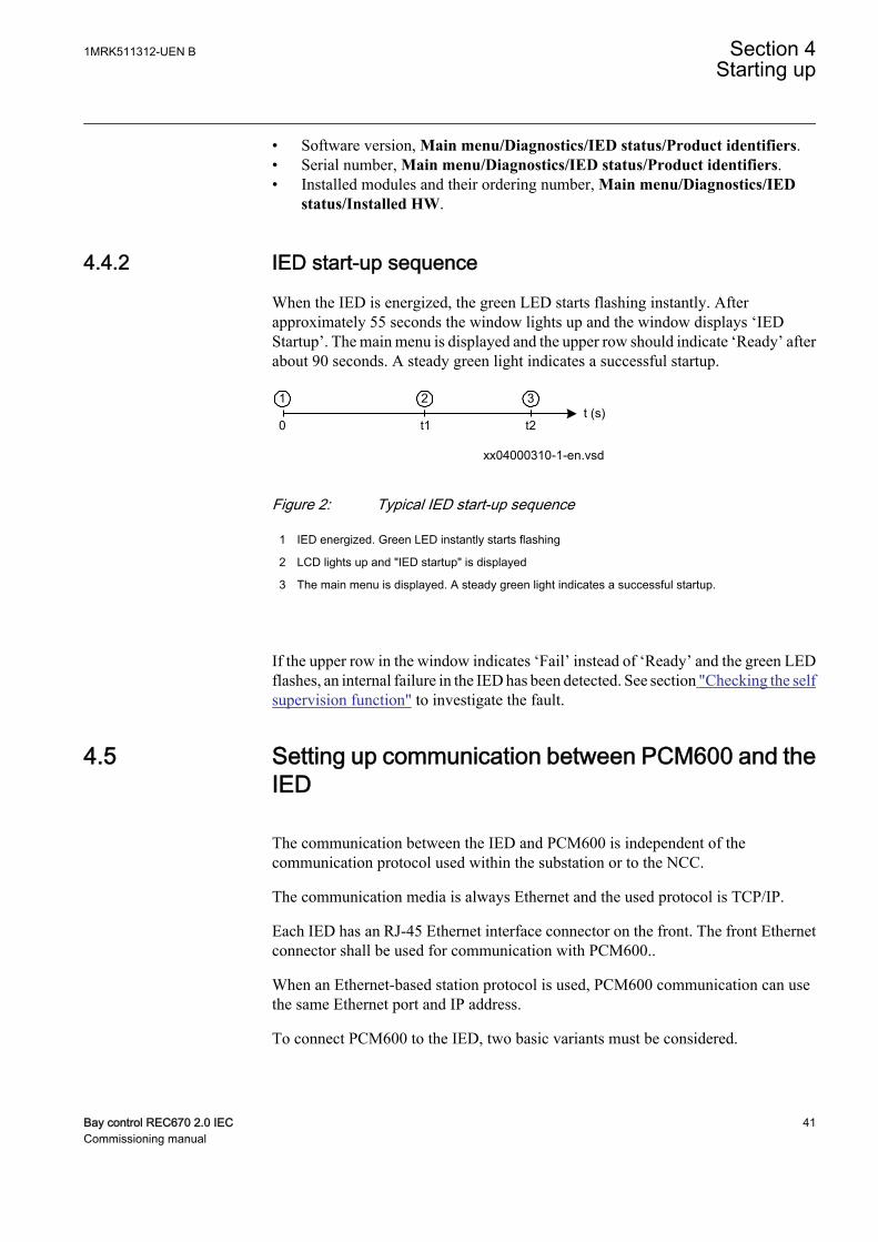
4.4.2 IED start-up sequence
When the IED is energized, the green LED starts flashing instantly. Afterapproximately 55 seconds the window lights up and the window displays ‘IEDStartup’. The main menu is displayed and the upper row should indicate ‘Ready’ afterabout 90 seconds. A steady green light indicates a successful startup.
xx04000310-1-en.vsd
t (s)0 t1 t2
1 32
IEC04000310 V2 EN
Figure 2: Typical IED start-up sequence
1 IED energized. Green LED instantly starts flashing
2 LCD lights up and "IED startup" is displayed
3 The main menu is displayed. A steady green light indicates a successful startup.
If the upper row in the window indicates ‘Fail’ instead of ‘Ready’ and the green LEDflashes, an internal failure in the IED has been detected. See section "Checking the selfsupervision function" to investigate the fault.
4.5 Setting up communication between PCM600 and theIED
The communication between the IED and PCM600 is independent of thecommunication protocol used within the substation or to the NCC.
The communication media is always Ethernet and the used protocol is TCP/IP.
Each IED has an RJ-45 Ethernet interface connector on the front. The front Ethernetconnector shall be used for communication with PCM600..
When an Ethernet-based station protocol is used, PCM600 communication can usethe same Ethernet port and IP address.
To connect PCM600 to the IED, two basic variants must be considered.
1MRK511312-UEN B Section 4Starting up
Bay control REC670 2.0 IEC 41Commissioning manual
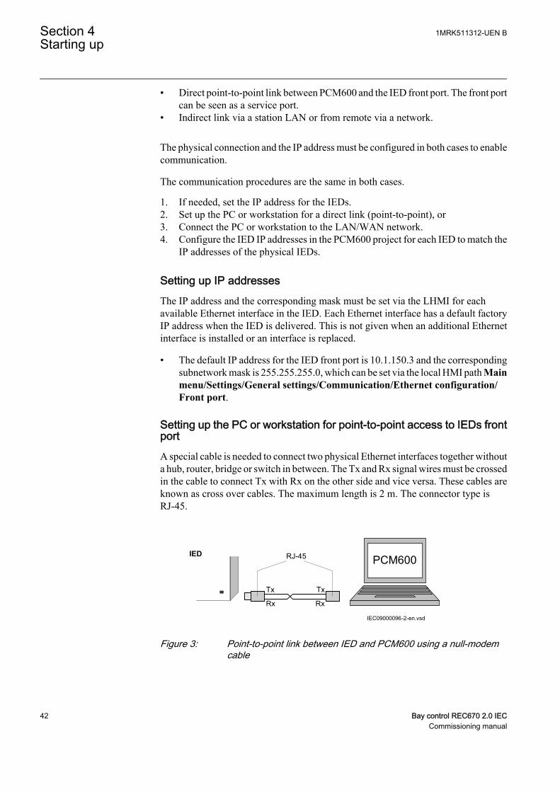
• Direct point-to-point link between PCM600 and the IED front port. The front portcan be seen as a service port.
• Indirect link via a station LAN or from remote via a network.
The physical connection and the IP address must be configured in both cases to enablecommunication.
The communication procedures are the same in both cases.
1. If needed, set the IP address for the IEDs.2. Set up the PC or workstation for a direct link (point-to-point), or3. Connect the PC or workstation to the LAN/WAN network.4. Configure the IED IP addresses in the PCM600 project for each IED to match the
IP addresses of the physical IEDs.
Setting up IP addressesThe IP address and the corresponding mask must be set via the LHMI for eachavailable Ethernet interface in the IED. Each Ethernet interface has a default factoryIP address when the IED is delivered. This is not given when an additional Ethernetinterface is installed or an interface is replaced.
• The default IP address for the IED front port is 10.1.150.3 and the correspondingsubnetwork mask is 255.255.255.0, which can be set via the local HMI path Mainmenu/Settings/General settings/Communication/Ethernet configuration/Front port.
Setting up the PC or workstation for point-to-point access to IEDs frontportA special cable is needed to connect two physical Ethernet interfaces together withouta hub, router, bridge or switch in between. The Tx and Rx signal wires must be crossedin the cable to connect Tx with Rx on the other side and vice versa. These cables areknown as cross over cables. The maximum length is 2 m. The connector type isRJ-45.
IEC09000096-2-en.vsd
Tx Tx
Rx Rx
RJ-45IEDPCM600
IEC09000096 V2 EN
Figure 3: Point-to-point link between IED and PCM600 using a null-modemcable
Section 4 1MRK511312-UEN BStarting up
42 Bay control REC670 2.0 IECCommissioning manual

The following description is an example valid for standard PCs using MicrosoftWindows operating system. The example is taken from a Laptop with one Ethernetinterface.
Administrator rights are required to change the PC communicationsetup. Some PCs have the feature to automatically detect that Txsignals from the IED are received on the Tx pin on the PC. Thus, astraight (standard) Ethernet cable can be used.
1. Select Search programs and files in the Start menu in Windows.
IEC13000057-1-en.vsd
IEC13000057 V1 EN
Figure 4: Select: Search programs and files
2. Type View network connections and click on the View network connectionsicon.
1MRK511312-UEN B Section 4Starting up
Bay control REC670 2.0 IEC 43Commissioning manual
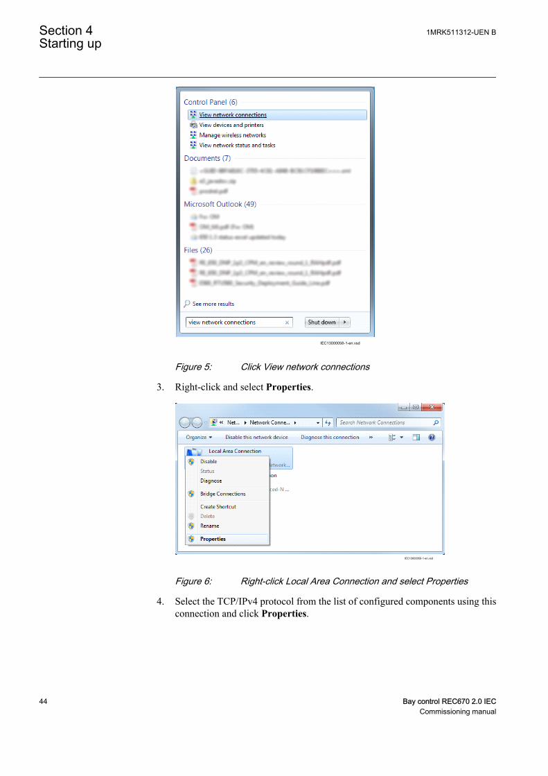
IEC13000058-1-en.vsd
IEC13000058 V1 EN
Figure 5: Click View network connections
3. Right-click and select Properties.
IEC13000059-1-en.vsd
IEC13000059 V1 EN
Figure 6: Right-click Local Area Connection and select Properties
4. Select the TCP/IPv4 protocol from the list of configured components using thisconnection and click Properties.
Section 4 1MRK511312-UEN BStarting up
44 Bay control REC670 2.0 IECCommissioning manual
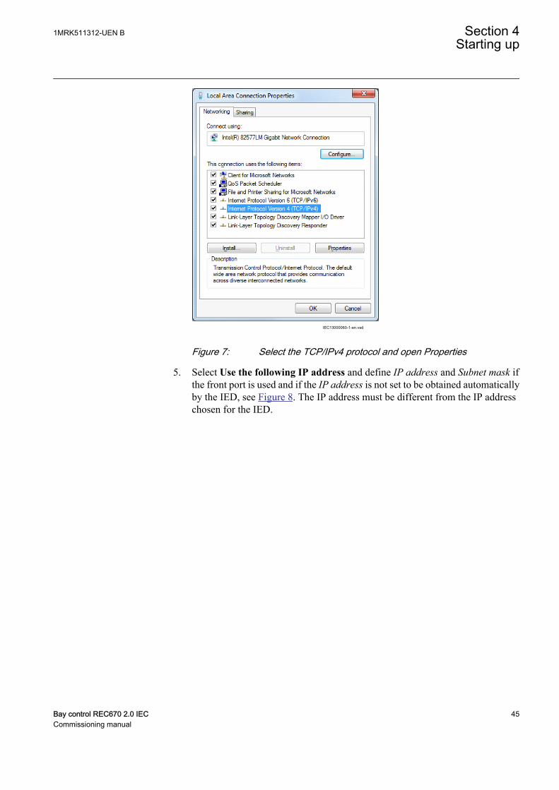
IEC13000060-1-en.vsd
IEC13000060 V1 EN
Figure 7: Select the TCP/IPv4 protocol and open Properties
5. Select Use the following IP address and define IP address and Subnet mask ifthe front port is used and if the IP address is not set to be obtained automaticallyby the IED, see Figure 8. The IP address must be different from the IP addresschosen for the IED.
1MRK511312-UEN B Section 4Starting up
Bay control REC670 2.0 IEC 45Commissioning manual
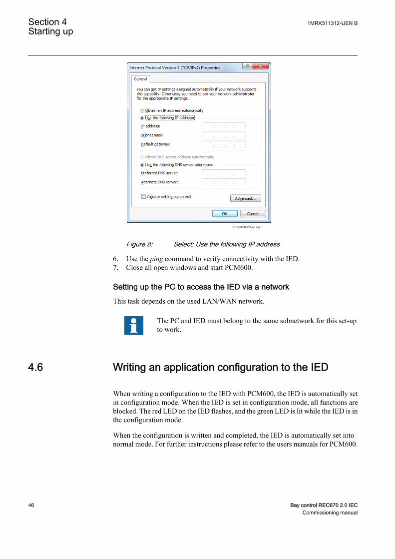
IEC13000062-1-en.vsd
IEC13000062 V1 EN
Figure 8: Select: Use the following IP address
6. Use the ping command to verify connectivity with the IED.7. Close all open windows and start PCM600.
Setting up the PC to access the IED via a networkThis task depends on the used LAN/WAN network.
The PC and IED must belong to the same subnetwork for this set-upto work.
4.6 Writing an application configuration to the IED
When writing a configuration to the IED with PCM600, the IED is automatically setin configuration mode. When the IED is set in configuration mode, all functions areblocked. The red LED on the IED flashes, and the green LED is lit while the IED is inthe configuration mode.
When the configuration is written and completed, the IED is automatically set intonormal mode. For further instructions please refer to the users manuals for PCM600.
Section 4 1MRK511312-UEN BStarting up
46 Bay control REC670 2.0 IECCommissioning manual
4.7 Checking CT circuits
Check that the wiring is in strict accordance with the suppliedconnection diagram.
The CTs must be connected in accordance with the circuit diagram provided with theIED, both with regards to phases and polarity. The following tests shall be performedon every primary CT connected to the IED:
• Primary injection test to verify the current ratio of the CT, the correct wiring upto the protection IED and correct phase sequence connection (that is L1, L2, L3.)
• Polarity check to prove that the predicted direction of secondary current flow iscorrect for a given direction of primary current flow. This is an essential test forthe proper operation of the differential function and directional protectionfunctions.
• CT secondary loop resistance measurement to confirm that the currenttransformer secondary loop DC resistance is within the specification for theconnected protection functions. When the measured loop resistance is near thecalculated value for maximum DC resistance, perform a complete burden test.
• CT excitation test in order to confirm that the current transformer is of the correctaccuracy rating and that there are no shorted turns in the current transformerwindings. Manufacturer's design curves must be available for the currenttransformer to compare the actual results.
• Earthing check of the individual CT secondary circuits to verify that each three-phase set of main CTs is properly connected to the station earth and only at oneelectrical point.
• Insulation resistance check.
While the CT primary is energized, the secondary circuit shall neverbe open circuited because extremely dangerous high voltages mayarise.
Both the primary and the secondary sides must be disconnected fromthe line and the IED when plotting the excitation characteristics.
If the CT secondary circuit earth connection is removed without thecurrent transformer primary being de-energized, dangerous voltagesmay result in the secondary CT circuits.
1MRK511312-UEN B Section 4Starting up
Bay control REC670 2.0 IEC 47Commissioning manual
4.8 Checking VT circuits
Check that the wiring is in strict accordance with the supplied connection diagram.
Correct possible errors before continuing to test the circuitry.
Test the circuitry.
• Polarity check when applicable; this test is often omitted for CVTs• VT circuit voltage measurement (primary injection test)• Earthing check• Phase relationship• Insulation resistance check
The primary injection test verifies the VT ratio and the wiring all the way from theprimary system to the IED. Injection must be performed for each phase-to-neutralcircuit.
While testing VT secondary circuit and associated secondaryequipment, care shall be exercised to isolate the VT from the circuitbeing tested to avoid backcharging the VT from the secondary side.
4.9 Using the RTXP test switch
The RTXP test switch is designed to provide the means of safe testing of the IED. Thisis achieved by the electromechanical design of the test switch and test plug handle.When the test plug handle is inserted, it first blocks the trip and alarm circuits then itshort circuits the CT secondary circuit and opens the VT secondary circuits makingthe IED available for secondary injection.
When pulled out, the test handle is mechanically stopped in half withdrawn position.In this position, the current and voltage enter the protection, but the alarm and tripcircuits are still isolated and the IED is in test mode. Before removing the test handle,check the measured values in the IED.
Not until the test handle is completely removed, the trip and alarm circuits are restoredfor operation.
Section 4 1MRK511312-UEN BStarting up
48 Bay control REC670 2.0 IECCommissioning manual
Verify that the contact sockets have been crimped correctly and thatthey are fully inserted by tugging on the wires. Never do this withcurrent circuits in service.
Current circuit
1. Verify that the contacts are of current circuit type.2. Verify that the short circuit jumpers are located in the correct slots.
Voltage circuit
1. Verify that the contacts are of voltage circuit type.2. Check that no short circuit jumpers are located in the slots dedicated for voltage.
Trip and alarm circuits
1. Check that the correct types of contacts are used.
4.10 Checking the binary input/output circuits
Do not insert anything else to the female connector but thecorresponding male connector. Inserting anything else (such as ameasurement probe) may damage the female connector and prevent aproper electrical contact between the printed circuit board and theexternal wiring connected to the screw terminal block.
4.10.1 Binary input circuits
Preferably, disconnect the binary input connector from the binary input cards. Checkall connected signals so that both input level and polarity are in accordance with theIED specifications.
4.10.2 Binary output circuits
Preferably, disconnect the binary output connector from the binary output cards.Check all connected signals so that both load and polarity are in accordance with IEDspecifications.
4.11 Checking optical connections
Check that the Tx and Rx optical connections are correct.
1MRK511312-UEN B Section 4Starting up
Bay control REC670 2.0 IEC 49Commissioning manual

An IED equipped with optical connections has an minimum spacerequirement of 180 mm for plastic fiber cables and 275 mm for glassfiber cables. Check the allowed minimum bending radius from theoptical cable manufacturer.
Section 4 1MRK511312-UEN BStarting up
50 Bay control REC670 2.0 IECCommissioning manual

Section 5 Configuring the IED and changing settings
5.1 Overview
The customer specific values for each setting parameter and a configuration file haveto be available before the IED can be set and configured, if the IED is not deliveredwith a configuration.
Use the configuration tools in PCM600 to verify that the IED has the expectedconfiguration.
Each function included in the IED has several setting parameters, which have to be setin order to make the IED behave as intended. A factory default value is provided foreach parameter.The Parameter Setting Tool in PCM600 is used when changing settingparameters.
All settings can be
• Entered manually through the local HMI.• Written from a PC, either locally or remotely using PCM600. Front or rear port
communication has to be established before the settings can be written to the IED.
Make sure that the DC supply is not turned off when the IED saves thewritten configuration.
The IED uses a FLASH disk for storing configuration data and process data likecounters, object states, Local/Remote switch position etc. Since FLASH memory isused, measures have been taken in software to make sure that the FLASH disk is notworn out by too intensive storing of data.
This means, that to be absolutely sure that all data have been saved to FLASH, it isnecessary to leave the IED with auxiliary power connected after all thecommissioning is done (including setting the Local/Remote switch to the desiredposition) for at least one hour after the last commissioning action performed on theIED.
After that time has elapsed, it will be safe to turn the IED off, no data will be lost.
1MRK511312-UEN B Section 5Configuring the IED and changing settings
Bay control REC670 2.0 IEC 51Commissioning manual
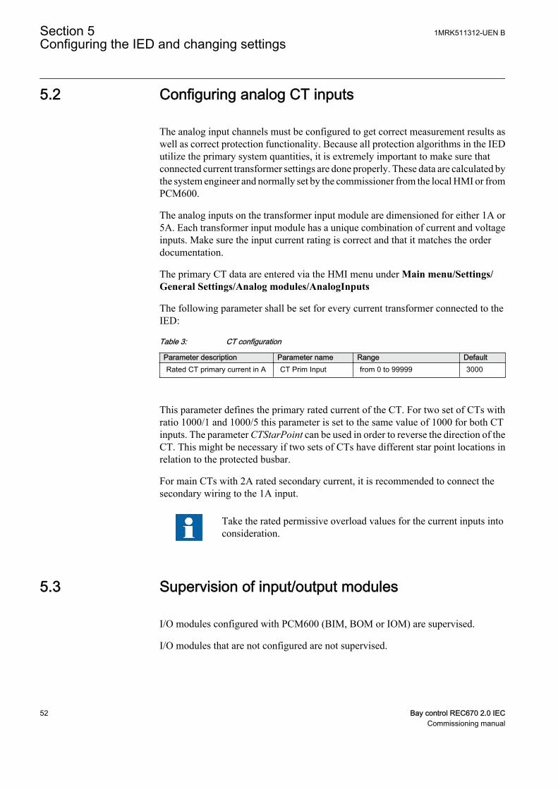
5.2 Configuring analog CT inputs
The analog input channels must be configured to get correct measurement results aswell as correct protection functionality. Because all protection algorithms in the IEDutilize the primary system quantities, it is extremely important to make sure thatconnected current transformer settings are done properly. These data are calculated bythe system engineer and normally set by the commissioner from the local HMI or fromPCM600.
The analog inputs on the transformer input module are dimensioned for either 1A or5A. Each transformer input module has a unique combination of current and voltageinputs. Make sure the input current rating is correct and that it matches the orderdocumentation.
The primary CT data are entered via the HMI menu under Main menu/Settings/General Settings/Analog modules/AnalogInputs
The following parameter shall be set for every current transformer connected to theIED:
Table 3: CT configuration
Parameter description Parameter name Range DefaultRated CT primary current in A CT Prim Input from 0 to 99999 3000
This parameter defines the primary rated current of the CT. For two set of CTs withratio 1000/1 and 1000/5 this parameter is set to the same value of 1000 for both CTinputs. The parameter CTStarPoint can be used in order to reverse the direction of theCT. This might be necessary if two sets of CTs have different star point locations inrelation to the protected busbar.
For main CTs with 2A rated secondary current, it is recommended to connect thesecondary wiring to the 1A input.
Take the rated permissive overload values for the current inputs intoconsideration.
5.3 Supervision of input/output modules
I/O modules configured with PCM600 (BIM, BOM or IOM) are supervised.
I/O modules that are not configured are not supervised.
Section 5 1MRK511312-UEN BConfiguring the IED and changing settings
52 Bay control REC670 2.0 IECCommissioning manual

Each logical I/O module has an error flag that indicates signal or module failure. Theerror flag is also set when the physical I/O module of the correct type is not detectedin the connected slot.
1MRK511312-UEN B Section 5Configuring the IED and changing settings
Bay control REC670 2.0 IEC 53Commissioning manual

54
Section 6 Establishing connection and verifying theSPA/IEC communication
6.1 Entering settings
If the IED is connected to a monitoring or control system via the rear SPA/IEC port,the SPA/IEC port has to be set either for SPA or IEC use.
6.1.1 Entering SPA settings
The SPA/IEC port is located on the rear side of the IED. Two types of interfaces canbe used:
• for plastic fibres with connector type HFBR• for glass fibres with connectors type ST
When using the SPA protocol, the rear SPA/IEC port must be set for SPA use.
Procedure
1. Set the operation of the rear optical SPA/IEC port to “SPA”.The operation of the rear SPA port can be found on the local HMI under Mainmenu/Configuration/Communication/Station communication/Portconfiguration/SLM optical serial port/PROTOCOL:1When the setting is entered the IED restarts automatically. After the restart theSPA/IEC port operates as a SPA port.
2. Set the slave number and baud rate for the rear SPA portThe slave number and baud rate can be found on the local HMI under Mainmenu/Configuration/Communication/Station communication/SPA/SPA:1Set the same slave number and baud rate as set in the SMS system for the IED.
6.1.2 Entering IEC settings
When using the IEC protocol, the rear SPA/IEC port must be set for IEC use.
Two types of interfaces can be used:
• for plastic fibres with connector type HFBR• for glass fibres with connectors type ST
Procedure
1MRK511312-UEN B Section 6Establishing connection and verifying the SPA/IEC communication
Bay control REC670 2.0 IEC 55Commissioning manual
1. Set the operation of the rear SPA/IEC port to “IEC”.The operation of the rear SPA/IEC port can be found on the local HMI underMain menu/Configuration/Communication/SLM configuration/Rearoptical SPA-IEC-DNP port/PROTOCOL:1When the setting is entered the IED restarts automatically. After the restart theselected IEC port operates as an IEC port.
2. Set the slave number and baud rate for the rear IEC port.The slave number and baud rate can be found on the local HMI under Mainmenu/Configuration/Communication/SLM configuration/Rear opticalSPA-IEC-DNP port/IEC60870–5–103Set the same slave number and baud rate as set in the IEC master system for theIED.
6.2 Verifying the communication
To verify that the rear communication with the SMS/SCS system is working, there aresome different methods. Choose one of the following.
6.2.1 Verifying SPA communication
Procedure
1. Use a SPA-emulator and send “RF” to the IED. The answer from the IED shouldbe the type and version of it, for example, “REL670 2.1...”.
2. Generate one binary event by activating a function, which is configured to anEVENT block where the used input is set to generate events on SPA. Theconfiguration must be made with the PCM600 software. Verify that the event ispresented in the SMS/SCS system.
During the following tests of the different functions in the IED, verify that the eventsand indications in the SMS/SCS system are as expected.
6.2.2 Verifying IEC communication
To verify that the IEC communication with the IEC master system is working, thereare some different methods. Choose one of the following.
Procedure
Section 6 1MRK511312-UEN BEstablishing connection and verifying the SPA/IEC communication
56 Bay control REC670 2.0 IECCommissioning manual
1. Check that the master system time-out for response from the IED, for exampleafter a setting change, is > 40 seconds.
2. Use a protocol analyzer and record the communication between the IED and theIEC master. Check in the protocol analyzer’s log that the IED answers the mastermessages.
3. Generate one binary event by activating a function that is configured to an eventblock where the used input is set to generate events on IEC. The configurationmust be made with the PCM600 software. Verify that the event is presented inthe IEC master system.
During the following tests of the different functions in the IED, verify that the eventsand indications in the IEC master system are as expected.
6.3 Fibre optic loop
The SPA communication is mainly used for SMS. It can include different numericalIEDs with remote communication possibilities. The fibre optic loop can contain <20-30 IEDs depending on requirements on response time. Connection to a personalcomputer (PC) can be made directly (if the PC is located in the substation) or bytelephone modem through a telephone network with ITU (CCITT) characteristics.
Table 4: Max distances between IEDs/nodes
glass < 1000 m according to optical budget
plastic < 25 m (inside cubicle) according to optical budget
6.4 Optical budget calculation for serial communicationwith SPA/IEC
Table 5: Example
Distance 1 kmGlass
Distance 25 mPlastic
Maximum attenuation - 11 dB - 7 dB
4 dB/km multi mode: 820 nm - 62.5/125 um 4 dB -
0.16 dB/m plastic: 620 nm - 1mm - 4 dB
Margins for installation, aging, and so on 5 dB 1 dB
Losses in connection box, two contacts (0.5 dB/contact) 1 dB -
Losses in connection box, two contacts (1 dB/contact) - 2 dB
Margin for 2 repair splices (0.5 dB/splice) 1 dB -
Maximum total attenuation 11 dB 7 dB
1MRK511312-UEN B Section 6Establishing connection and verifying the SPA/IEC communication
Bay control REC670 2.0 IEC 57Commissioning manual

58
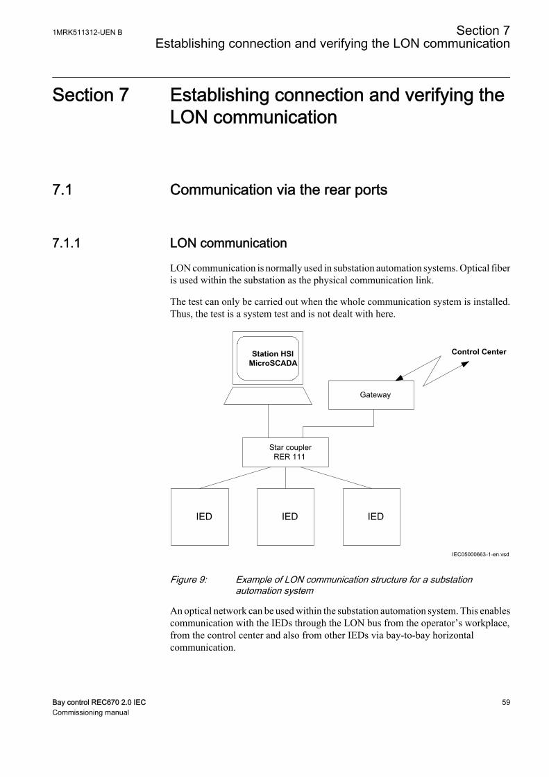
Section 7 Establishing connection and verifying theLON communication
7.1 Communication via the rear ports
7.1.1 LON communication
LON communication is normally used in substation automation systems. Optical fiberis used within the substation as the physical communication link.
The test can only be carried out when the whole communication system is installed.Thus, the test is a system test and is not dealt with here.
Control Center
IED IEDIED
Gateway
Star couplerRER 111
Station HSIMicroSCADA
IEC05000663-1-en.vsd
IEC05000663 V2 EN
Figure 9: Example of LON communication structure for a substationautomation system
An optical network can be used within the substation automation system. This enablescommunication with the IEDs through the LON bus from the operator’s workplace,from the control center and also from other IEDs via bay-to-bay horizontalcommunication.
1MRK511312-UEN B Section 7Establishing connection and verifying the LON communication
Bay control REC670 2.0 IEC 59Commissioning manual
The fibre optic LON bus is implemented using either glass core or plastic core fibreoptic cables.
Table 6: Specification of the fibre optic connectors
Glass fibre Plastic fibreCable connector ST-connector snap-in connector
Cable diameter 62.5/125 m 1 mm
Max. cable length 1000 m 10 m
Wavelength 820-900 nm 660 nm
Transmitted power -13 dBm (HFBR-1414) -13 dBm (HFBR-1521)
Receiver sensitivity -24 dBm (HFBR-2412) -20 dBm (HFBR-2521)
7.2.1 The LON Protocol
The LON protocol is specified in the LonTalkProtocol Specification Version 3 fromEchelon Corporation. This protocol is designed for communication in controlnetworks and is a peer-to-peer protocol where all the devices connected to the networkcan communicate with each other directly. For more information of the bay-to-baycommunication, refer to the section Multiple command function.
7.2.2 Hardware and software modules
The hardware needed for applying LON communication depends on the application,but one very central unit needed is the LON Star Coupler and optical fibres connectingthe star coupler to the IEDs. To interface the IEDs from the MicroSCADA withClassic Monitor, application library LIB520 is required.
The HV Control 670 software module is included in the LIB520 high-voltage processpackage, which is a part of the Application Software Library in MicroSCADAapplications.
The HV Control 670 software module is used for control functions in the IEDs. Themodule contains a process picture, dialogues and a tool to generate a process databasefor the control application in MicroSCADA.
When using MicroSCADA Monitor Pro instead of the Classic Monitor, SA LIB isused together with 670 series Object Type files.
The HV Control 670 software module and 670 series Object Typefiles are used with both 650 and 670 series IEDs.
Use the LON Network Tool (LNT) to set the LON communication. This is a softwaretool applied as one node on the LON bus. To communicate via LON, the IEDs needto know
Section 7 1MRK511312-UEN BEstablishing connection and verifying the LON communication
60 Bay control REC670 2.0 IECCommissioning manual

• The node addresses of the other connected IEDs.• The network variable selectors to be used.
This is organized by LNT.
The node address is transferred to LNT via the local HMI by setting the parameterServicePinMsg = Yes. The node address is sent to LNT via the LON bus, or LNT canscan the network for new nodes.
The communication speed of the LON bus is set to the default of 1.25 Mbit/s. This canbe changed by LNT.
The setting parameters for the LON communication are set via the local HMI. Referto the technical manual for setting parameters specifications.
The path to LON settings in the local HMI is Main menu/Configuration/Communication/SLM configuration/Rear optical LON port
If the LON communication from the IED stops, caused by setting of illegalcommunication parameters (outside the setting range) or by another disturbance, it ispossible to reset the LON port of the IED.
Path in the local HMI under Main menu/Configuration/Communication/SLMconfiguration/Rear optical LON port
These parameters can only be set with the LON Network Tool (LNT).
Table 7: Setting parameters for the LON communication
Parameter Range Default Unit Parameter descriptionDomainID 0 0 - Domain identification number
SubnetID* 0 - 255Step: 1
0 - Subnet identification number
NodeID* 0 - 127Step: 1
0 - Node identification number
*Can be viewed in the local HMI
Path in the local HMI under Main menu/Congifuration/Communication/SLMconfiguration/Rear optical LON port
These parameters can only be set with the LON Network Tool (LNT).
Table 8: LON node information parameters
Parameter Range Default Unit Parameter descriptionNeuronID* 0 - 12 Not loaded - Neuron hardware identification
number in hexadecimal code
Location 0 - 6 No value - Location of the node
*Can be viewed in the local HMI
1MRK511312-UEN B Section 7Establishing connection and verifying the LON communication
Bay control REC670 2.0 IEC 61Commissioning manual
Path in the local HMI under Main menu/Configuration/Communication/SLMconfiguration/Rear optical LON port
Table 9: ADE Non group settings (basic)
Name Values (Range) Unit Step Default DescriptionOperation Off
On- - Off Operation
TimerClass SlowNormalFast
- - Slow Timer class
Path in the local HMI under Main menu/Configuration/Communication/SLMconfiguration/Rear optical LON port
Table 10: LON commands
Command Command descriptionServicePinMsg Command with confirmation. Transfers the node address to the LON Network Tool.
7.2 Optical budget calculation for serial communicationwith LON
Table 11: Example
Distance 1 kmGlass
Distance10 mPlastic
Maximum attenuation -11 dB - 7 dB
4 dB/km multi mode: 820 nm - 62.5/125 um 4 dB -
0.3 dB/m plastic: 620 nm - 1mm - 3 dB
Margins for installation, aging, and so on 5 dB 2 dB
Losses in connection box, two contacts (0.75 dB/contact) 1.5 dB -
Losses in connection box, two contacts (1dB/contact) - 2 dB
Margin for repair splices (0.5 dB/splice) 0.5 dB -
Maximum total attenuation 11 dB 7 dB
Section 7 1MRK511312-UEN BEstablishing connection and verifying the LON communication
62 Bay control REC670 2.0 IECCommissioning manual
Section 8 Establishing connection and verifying theIEC 61850 communication
8.1 Overview
The rear OEM ports are used for:
• substation bus (IEC 61850-8-1) communication.
For IEC 61850-8-1 redundant communication, both rear OEM ports are utilized.
8.2 Setting the station communication
To enable IEC 61850 communication the corresponding OEM ports must beactivated. The rear OEM port AB and CD is used for IEC 61850-8-1 communication.The rear OEM port CD is used for IEC 61850-9-2LE communication. For IEC61850-8-1 redundant communication, both OEM port AB and CD are usedexclusively.
IEC 61850-9-2LE communication can only be used on OEM rear portX311:C, D.
To enable IEC 61850 station communication:
1. Enable IEC 61850-8-1 (substation bus) communication for port AB.1.1. Set values for the rear ports AB and CD.
Navigate to: Main menu/Configuration/Communication/Ethernetconfiguration/LANAB:1Set values for Mode, IPAddress and IPMask. Mode must be set to Normal.Check that the correct IP address is assigned to the port.
1.2. Enable IEC 61850-8-1 communication.Navigate to: Main menu/Configuration/Communication/Stationcommunication/IEC61850-8-1/IEC61850–8–1:1Set Operation to On and PortSelGOOSE to the port used (for exampleLANAB).
2. Enable redundant IEC 61850-8-1 communication for port AB and CD2.1. Enable redundant communication.
1MRK511312-UEN B Section 8Establishing connection and verifying the IEC 61850 communication
Bay control REC670 2.0 IEC 63Commissioning manual
Navigate to: Main menu/Configuration/Communication/Ethernetconfiguration/PRP:1Set values for Operation, IPAddress and IPMask. Operation must be set toOn.The IED will restart after confirmation. Menu items LANAB:1 andLANCD:1 are hidden in local HMI after restart but are visible in PSTwhere the values for parameter Mode is set to Duo.
3. Enable IEC 61850-9-2LE (process bus) communication for port CD.3.1. Set values for the rear port CD.
Navigate to: Main menu/Configuration/Communication/Ethernetconfiguration/LANCD:1Set values for Mode, IPAddress and IPMask. Mode must be set to IEC9-2.
There are no settings needed for the IEC 61850-9-2LE communication in the localHMI branch Station communication. Make sure that the optical fibres are connectedcorrectly. Communication is enabled whenever the merging unit starts sending data.
8.3 Verifying the communication
To verify that the communication is working a test/analyzing tool, for exampleITT600, can be used.
Verifying redundant IEC 61850-8-1 communicationEnsure that the IED receives IEC 61850-8-1 data on both port AB and CD. Browse inthe local HMI to Main menu/Diagnostics/Communication/Redundant PRP andcheck that both signals LAN-A-STATUS and LAN-B-STATUS are shown as Ok.Remove the optical connection to one of the ports AB or CD. Verify that either signalLAN-A-STATUS or LAN-B-STATUS (depending on which connection that wasremoved) are shown as Error and the that other signal is shown as Ok. Be sure to re-connect the removed connection after completed verification.
Section 8 1MRK511312-UEN BEstablishing connection and verifying the IEC 61850 communication
64 Bay control REC670 2.0 IECCommissioning manual

Section 9 Testing IED operation
9.1 Preparing for test
9.1.1 Requirements
IED test requirements:
• Calculated settings• Application configuration diagram• Signal matrix (SMT) configuration• Terminal connection diagram• Technical manual• Three-phase test equipment• Process bus, IEC61850-9-2LE, MU test simulator, if IEC 61850-9-2LE process
bus communication is used.• PCM600
The setting and configuration of the IED must be completed before the testing canstart.
The terminal diagram, available in the technical reference manual, is a generaldiagram of the IED.
Note that the same diagram is not always applicable to each specificdelivery (especially for the configuration of all the binary inputs andoutputs).
Therefore, before testing, check that the available terminal diagram corresponds to theIED.
The technical manual contains application and functionality summaries, functionblocks, logic diagrams, input and output signals, setting parameters and technical datasorted per function.
The test equipment should be able to provide a three-phase supply of voltages andcurrents. The magnitude of voltage and current as well as the phase angle betweenvoltage and current must be variable. The voltages and currents from the testequipment must be obtained from the same source and they must have minimalharmonic content. If the test equipment cannot indicate the phase angle, a separatephase-angle measuring instrument is necessary.
1MRK511312-UEN B Section 9Testing IED operation
Bay control REC670 2.0 IEC 65Commissioning manual
Prepare the IED for test before testing a particular function. Consider the logicdiagram of the tested protection function when performing the test. All includedfunctions in the IED are tested according to the corresponding test instructions in thischapter. The functions can be tested in any order according to user preferences. Onlythe functions that are used (Operation is set to On) should be tested.
The response from a test can be viewed in different ways:
• Binary outputs signals• Service values on the local HMI (logical signals or phasors)• A PC with PCM600 application configuration software in work online mode
All setting groups that are used should be tested.
This IED is designed for a maximum continuous current of four timesthe rated current.
All references to CT and VT must be interpreted as analog valuesreceived from merging units (MU) via IEC 61850-9-2LEcommunication protocol, analog values received from thetransformer input module, or analog values received from the LDCM.
When using a MU test simulator, make sure it is set to the correctSVID and that the system frequency is set to the same as in the IED.
Please observe the measuring accuracy of the IED, the test equipmentand the angular accuracy for both of them.
Please consider the configured logic from the function block to theoutput contacts when measuring the operate time.
After intense testing, it is important that the IED is not immediatelyrestarted, which might cause a faulty trip due to flash memoryrestrictions. Some time must pass before the IED is restarted. Formore information about the flash memory, refer to section“Configuring the IED and changing settings”.
Section 9 1MRK511312-UEN BTesting IED operation
66 Bay control REC670 2.0 IECCommissioning manual

9.1.2 Preparing the IED to verify settings
If a test switch is included, start preparation by making the necessary connections tothe test switch. This means connecting the test equipment according to a specific anddesignated IED terminal diagram.
Put the IED into the test mode to facilitate the test of individual functions and preventunwanted operation caused by other functions. The busbar differential protection isnot included in the test mode and is not prevented to operate during the test operations.The test switch should then be connected to the IED.
Verify that analog input signals from the analog input module are measured andrecorded correctly by injecting currents and voltages required by the specific IED.
To make testing even more effective, use PCM600. PCM600 includes the Signalmonitoring tool, which is useful in reading the individual currents and voltages, theiramplitudes and phase angles. In addition, PCM600 contains the Disturbance handlingtool. The content of reports generated by the Disturbance handling tool can beconfigured which makes the work more efficient. For example, the tool may beconfigured to only show time tagged events and to exclude analog information and soon.
Check the disturbance report settings to ensure that the indications are correct.
For test functions and test and signal parameter names, see the technical referencemanual. The correct initiation of the disturbance recorder is made on start and/orrelease or trip from a function. Also check that the wanted recordings of analog (realand calculated) and binary signals are achieved.
Parameters can be entered into different setting groups. Make sure totest functions for the same parameter setting group. If needed, repeatthe tests for all different setting groups used. The difference betweentesting the first parameter setting group and the remaining is that thereis no need for testing the connections.
During testing, observe that the right testing method, that corresponds to the actualparameters set in the activated parameter setting group, is used.
Set and configure the function(s) before testing. Most functions are highly flexible andpermit a choice of functional and tripping modes. The various modes are checked atthe factory as part of the design verification. In certain cases, only modes with a highprobability of coming into operation need to be checked when commissioned to verifythe configuration and settings.
1MRK511312-UEN B Section 9Testing IED operation
Bay control REC670 2.0 IEC 67Commissioning manual
9.2 Activating the test mode
Put the IED into the test mode before testing. The test mode blocks all protectionfunctions and some of the control functions in the IED, and the individual functions tobe tested can be unblocked to prevent unwanted operation caused by other functions.In this way, it is possible to test slower back-up measuring functions without theinterference from faster measuring functions. The busbar differential protection is notincluded in the test mode and is not prevented to operate during the test operations.The test switch should then be connected to the IED.Test mode is indicated when theyellow StartLED flashes.
It is important that the IED function to be tested is put into test mode, even if the MUis sending data marked as "test". The IED will interpret these data as valid if it is notin test mode.
1. Browse to the TestMode menu and press E.The TestMode menu is found on the local HMI under Main menu/Test/IEDtest mode/TestMode
2. Use the up and down arrows to choose On and press E.3. Press the left arrow to exit the menu.
The dialog box Save changes appears.4. Choose Yes, press E and exit the menu.
The yellow startLED above the LCD will start flashing when the IED is in testmode.
9.3 Preparing the connection to the test equipment
The IED can be equipped with a test switch of type RTXP8, RTXP18 or RTXP24. Thetest switch and its associated test plug handle (RTXH8, RTXH18 or RTXH24) are apart of the COMBITEST system, which provides secure and convenient testing of theIED.
When using the COMBITEST, preparations for testing are automatically carried outin the proper sequence, that is, for example, blocking of tripping circuits, shortcircuiting of CTs, opening of voltage circuits, making IED terminals available forsecondary injection. Terminals 1 and 8, 1 and 18 as well as 1 and 12 of the test switchesRTXP8, RTXP18 and RTXP24 respectively are not disconnected as they supply DCpower to the protection IED.
The RTXH test-plug handle leads may be connected to any type of test equipment orinstrument. When a number of protection IEDs of the same type are tested, the test-plug handle only needs to be moved from the test switch of one protection IED to thetest switch of the other, without altering the previous connections.
Use COMBITEST test system to prevent unwanted tripping when the handle iswithdrawn, since latches on the handle secure it in the half withdrawn position. In this
Section 9 1MRK511312-UEN BTesting IED operation
68 Bay control REC670 2.0 IECCommissioning manual
position, all voltages and currents are restored and any re-energizing transients aregiven a chance to decay before the trip circuits are restored. When the latches arereleased, the handle can be completely withdrawn from the test switch, restoring thetrip circuits to the protection IED.
If a test switch is not used, perform measurement according to the provided circuitdiagrams.
Never disconnect the secondary connection of a current transformercircuit without first short-circuiting the transformer's secondarywinding. Operating a current transformer with the secondary windingopen will cause a massive potential build up that may damage thetransformer and cause personal injury.
9.4 Connecting the test equipment to the IED
Connect the test equipment according to the IED specific connection diagram and theneeded input and output signals for the function under test. An example of aconnection is shown in figure 10.
Connect the current and voltage terminals. Pay attention to the current polarity. Makesure that the connection of input and output current terminals and the connection of theresidual current conductor is correct. Check that the input and output logical signalsin the logic diagram for the function under test are connected to the correspondingbinary inputs and outputs of the IED under test.
The MU test equipment must be connected to the CD port on the OEMmodule when process bus IEC61850-9-2LE communication is used.
To ensure correct results, make sure that the IED as well as the testequipment are properly earthed before testing.
1MRK511312-UEN B Section 9Testing IED operation
Bay control REC670 2.0 IEC 69Commissioning manual

IL1IL2IL3IN
UL1UL2UL3UN
IL1IL2IL3
UL1
IN (I4,I5)
TRIP L1TRIP L2TRIP L3
Test
equ
ipm
ent
IED
IEC09000652-1-en.vsd
UL2UL3UNUN (U4,U5)
IEC 61850
IEC09000652 V1 EN
Figure 10: Connection example of the test equipment to the IED when testequipment is connected to the transformer input module
9.5 Releasing the function to be tested
Release or unblock the function to be tested. This is done to ensure that only thefunction or the chain of functions to be tested are in operation and that other functionsare prevented from operating. Release the tested function(s) by setting thecorresponding Blocked parameter under Function test modes to No in the local HMI.
When testing a function in this blocking feature, remember that not only the actualfunction must be activated, but the whole sequence of interconnected functions (frommeasuring inputs to binary output contacts), including logic must be activated. Beforestarting a new test mode session, scroll through every function to ensure that only thefunction to be tested (and the interconnected ones) have the parameters Blocked andeventually EvDisable set to No and Yes respectively. Remember that a function is alsoblocked if the BLOCK input signal on the corresponding function block is active,which depends on the configuration. Ensure that the logical status of the BLOCKinput signal is equal to 0 for the function to be tested. Event function blocks can alsobe individually blocked to ensure that no events are reported to a remote station duringthe test. This is done by setting the parameter EvDisable to Yes.
Any function is blocked if the corresponding setting in the local HMIunder Main menu/Test/Function test modes menu remains On, thatis, the parameter Blocked is set to Yes and the parameter TESTMODEunder Main menu/Test/IED test mode remains active. All functionsthat were blocked or released in a previous test mode session, that is,
Section 9 1MRK511312-UEN BTesting IED operation
70 Bay control REC670 2.0 IECCommissioning manual
the parameter Test mode is set to On, are reset when a new test modesession is started.
Procedure
1. Click the Function test modes menu.The Function test modes menu is located in the local HMI under Main menu/Test/Function test modes.
2. Browse to the function instance that needs to be released.3. Set parameter Blocked for the selected function to No.
9.6 Verifying analog primary and secondarymeasurement
Verify that the connections are correct and that measuring and scaling is donecorrectly. This is done by injecting current and voltage to the IED.
Besides verifying analog input values from the merging unit via the IEC 61850-9-2-LE process bus, analog values from the transformer input module can be verified asfollows.
Apply input signals as needed according to the actual hardware andthe application configuration.
1. Inject a symmetrical three-phase voltage and current at rated value.2. Compare the injected value with the measured values.
The voltage and current phasor menu in the local HMI is located under Mainmenu/Measurements/Analog primary values and Main menu/Measurements/Analog secondary values.
3. Compare the frequency reading with the set frequency and the direction of thepower.The frequency and active power are located under Main menu/Measurements/Monitoring/ServiceValues(MMXN)/CVMMXN:x. Then navigate to thebottom of the list to find the frequency.
4. Inject an unsymmetrical three-phase voltage and current, to verify that phasesare correctly connected.
If some setting deviates, check the analog input settings under
Main menu/Settings/General settings/Analog modules
1MRK511312-UEN B Section 9Testing IED operation
Bay control REC670 2.0 IEC 71Commissioning manual

If the IEC61850-9-2LE communication is interrupted during currentinjection, the report tool in PCM600 will display the current that wasinjected before the interrupt.
IEC10000032-1-en.vsd
IEC10000032 V1 EN
Figure 11: PCM600 report tool display after communication interrupt
9.7 Testing the protection functionality
Each protection function must be tested individually by secondary injection.
• Verify operating levels (trip) and timers.• Verify alarm and blocking signals.• Use the disturbance handling tool in PCM600 to evaluate that the protection
function has received the correct data and responded correctly (signaling andtiming).
• Use the event viewer tool in PCM600 to check that only expected events haveoccurred.
Section 9 1MRK511312-UEN BTesting IED operation
72 Bay control REC670 2.0 IECCommissioning manual
Section 10 Testing functionality by secondaryinjection
10.1 Testing disturbance report
10.1.1 Introduction
The following sub-functions are included in the disturbance report function:
• Disturbance recorder• Event list• Event recorder• Fault locator• Trip value recorder• Indications
If the disturbance report is set on, then its sub-functions are also set up and so it is notpossible to only switch these sub-functions off. The disturbance report function isswitched off (parameter Operation = Off) in PCM600 or the local HMI under Mainmenu/Settings/IED Settings/Monitoring/Disturbance report/DRPRDRE:1.
10.1.2 Disturbance report settings
When the IED is in test mode, the disturbance report can be made active or inactive.If the disturbance recorder is turned on during test mode, recordings will be made.When test mode is switched off all recordings made during the test session are cleared.
Setting OpModeTest for the control of the disturbance recorder during test mode arelocated on the local HMI under Main menu/Settings/IED Settings/Monitoring/Disturbance report/DRPRDRE:1.
10.1.3 Disturbance recorder (DR)
A Manual Trig can be started at any time. This results in a recording of the actualvalues from all recorded channels.
The Manual Trig can be started in two ways:
1. From the local HMI under Main menu/Disturbance records.1.1. Enter on the row at the bottom of the HMI called Manual trig.
1MRK511312-UEN B Section 10Testing functionality by secondary injection
Bay control REC670 2.0 IEC 73Commissioning manual
A new recording begins. The view is updated if you leave the menu andreturn.
1.2. Navigate to General information or to Trip values to obtain more detailedinformation.
2. Open the Disturbance handling tool for the IED in the plant structure in PCM600.2.1. Right-click and select Execute manual Trig in the window Available
recordings in IED.2.2. Read the required recordings from the IED.2.3. Refresh the window Recordings and select a recording.2.4. Right-click and select Create Report or Open With to export the recordings
to any disturbance analyzing tool that can handle Comtrade formatted files.
Evaluation of the results from the disturbance recording function requires access to aPC either permanently connected to the IED or temporarily connected to the Ethernetport (RJ-45) on the front. The PCM600 software package must be installed in the PC.
Disturbance upload can be performed by the use of PCM600 or by any third party toolwith IEC 61850 protocol. Reports can automatically be generated from PCM600.Disturbance files can be analyzed by any tool reading Comtrade formatteddisturbance files.
It could be useful to have a printer for hard copies. The correct start criteria andbehavior of the disturbance recording function can be checked when IED protectivefunctions are tested.
When the IED is brought into normal service it is recommended to delete allrecordings, made during commissioning to avoid confusion in future fault analysis.
All recordings in the IED can be deleted in two ways:
1. in the local HMI under Main menu/Clear/Reset disturbances, or2. in the Disturbance handling tool in PCM600 by selecting Delete all recordings in
the IED... in the window Available Recordings in IED.
10.1.4 Event recorder (ER) and Event list (EL)
The result from the event recorder and event list can be viewed on the local HMI or,after upload, in PCM600 as follows:
1. on the local HMI under Main menu/Events, or in more details via2. the Event Viewer in PCM600.
The internal FIFO register of all events will appear when the event viewer islaunched.
When the IED is brought into normal service it is recommended to delete all eventsresulting from commissioning tests to avoid confusion in future fault analysis. Allevents in the IED can be cleared in the local HMI under Main Menu//Clear/Clear
Section 10 1MRK511312-UEN BTesting functionality by secondary injection
74 Bay control REC670 2.0 IECCommissioning manual

internal event list or Main menu/Clear/Clear process event list. It is not possibleto clear the event lists from PCM600.
When testing binary inputs, the event list (EL) might be used instead. No uploading oranalyzing of registrations is then needed since the event list keeps running,independent of start of disturbance registration.
10.2 Identifying the function to test in the technicalreference manual
Use the technical manual to identify function blocks, logic diagrams, input and outputsignals, setting parameters and technical data.
10.3 Differential protection
10.3.1 High impedance differential protection HZPDIF
Prepare the IED for verification of settings outlined in section "Requirements" andsection "Preparing for test" in this chapter.
10.3.1.1 Verifying the settings
1. Connect single-phase or three-phase test set to inject the operating voltage. Theinjection is done across the measuring branch.
The required trip and alarm voltage, as well as the usedstabilizing resistance value must be set in the function. Note aswell that used CT input in the IED must have ratio set as 1:1. Thisis essential for the measurement of the expected value. Normallya slightly higher operating value is no problem as the sensitivityis not influenced much.
2. Increase the voltage and make note of the operate value U>Trip. This is done bymanual testing and without trip of the test set.
3. Connect the trip contact to the test set to stop the test set for measurement of triptimes below.
4. Reduce the voltage slowly and make note of the reset value. The reset value mustbe high for this function.
5. Check the operating time by injecting a voltage corresponding to 1.2 ˣ U>Triplevel. Make note of the measured trip time.
6. If required, verify the trip time at another voltage. Normally 2 ˣ U>Trip isselected.
1MRK511312-UEN B Section 10Testing functionality by secondary injection
Bay control REC670 2.0 IEC 75Commissioning manual
7. If used, measure the alarm level operating value. Increase the voltage and makenote of the operate value U>Alarm. This is done with manual test and withouttrip of the test set.
8. Measure the operating time on the alarm output by connecting the stop of the testset to an output from tAlarm. Inject a voltage 1.2 ˣ U>Alarm and measure thealarm time.
9. Check that trip and alarm outputs operate according to the configuration logic.10. Finally check that start and alarm information is stored in the event menu and if
a serial connection to the SA is available verify that the correct and only therequired signals are presented on the local HMI and on the SCADA system.
Information on how to use the event menu is found in the operator'smanual.
10.3.1.2 Completing the test
Continue to test another function or end the test by changing the TestMode setting toOff. Restore connections and settings to their original values, if they were changed fortesting purposes.
10.4 Current protection
10.4.1 Instantaneous phase overcurrent protection 3-phase outputPHPIOC
Prepare the IED for verification of settings outlined in section "Requirements" andsection "Preparing for test" in this chapter.
To verify the settings the following fault type should be tested:
• Phase-to-earth fault
Ensure that the maximum continuous current, supplied from the current source usedfor the test of the IED, does not exceed four times the rated current value of the IED.
10.4.1.1 Measuring the operate limit of set values
1. Inject a phase current into the IED with an initial value below that of the setting.2. Set the operation mode to 1 out of 3.3. Increase the injected current in the Ln phase until the TRL (n=1–3) signal
appears.4. Switch the fault current off.
Section 10 1MRK511312-UEN BTesting functionality by secondary injection
76 Bay control REC670 2.0 IECCommissioning manual
Observe: Do not exceed the maximum permitted overloading ofthe current circuits in the IED.
5. Compare the measured operating current with the set value.6. Set the operation mode to 2 out of 3 and inject current into one of the phases.
Check - no operation.
10.4.1.2 Completing the test
Continue to test another function or end the test by changing the TestMode setting toOff. Restore connections and settings to their original values, if they were changed fortesting purposes.
10.4.2 Four step phase overcurrent protection 3-phase outputOC4PTOC
Prepare the IED for verification of settings outlined in section "Requirements" andsection "Preparing for test" in this chapter.
10.4.2.1 Verifying the settings
1. Connect the test set for current injection to the appropriate IED phases.If there is any configuration logic that is used to enable or block any of the fouravailable overcurrent steps, make sure that the step under test is enabled (forexample, end fault protection).If 1 out of 3 currents for operation is chosen: Connect the injection current tophases L1 and neutral.If 2 out of 3 currents for operation is chosen: Connect the injection current intophase L1 and out from phase L2.If 3 out of 3 currents for operation is chosen: Connect the symmetrical three-phase injection current into phases L1, L2 and L3.
2. Connect the test set for the appropriate three-phase voltage injection to the IEDphases L1, L2 and L3. The protection shall be fed with a symmetrical three-phase voltage.
3. Set the injected polarizing voltage slightly larger than the set minimumpolarizing voltage (default is 5% of UBase) and set the injection current to lagthe appropriate voltage by an angle of about 80° if forward directional functionis selected.If 1 out of 3 currents for operation is chosen: The voltage angle of phase L1 is thereference.If 2 out of 3 currents for operation is chosen: The voltage angle of phase L1 – thevoltage angle of L2 is the reference.If 3 out of 3 currents for operation is chosen: The voltage angle of phase L1 is thereference.
1MRK511312-UEN B Section 10Testing functionality by secondary injection
Bay control REC670 2.0 IEC 77Commissioning manual
If reverse directional function is selected, set the injection current to lag thepolarizing voltage by an angle equal to 260° (equal to 80° + 180°).
4. Increase the injected current and note the operate value of the tested step of thefunction.
5. Decrease the current slowly and note the reset value.6. If the test has been performed by injection of current in phase L1, repeat the test,
injecting current into phases L2 and L3 with polarizing voltage connected tophases L2, respectively L3 (1 out of 3 currents for operation).
7. If the test has been performed by injection of current in phases L1 – L2, repeatthe test, injecting current into phases L2 – L3 and L3 – L1 with the appropriatephase angle of injected currents.
8. Block higher set stages when testing lower set stages by following the proceduredescribed below.
9. Connect a trip output contact to a timer.10. Set the injected current to 200% of the operate level of the tested stage, switch
on the current and check the time delay.For inverse time curves, check the operate time at a current equal to 110% of theoperate current for txMin.
11. Check that all trip and start contacts operate according to the configuration(signal matrixes)
12. Reverse the direction of the injected current and check that the protection doesnot operate.
13. If 2 out of 3 or 3 out of 3 currents for operation is chosen: Check that the functionwill not operate with current in one phase only.
14. Repeat the above described tests for the higher set stages.15. Finally check that start and trip information is stored in the event menu.
Verification of the non-directional phase overcurrent function isdone as instructed above, without applying any polarizingvoltage.
10.4.2.2 Completing the test
Continue to test another function or end the test by changing the TestMode setting toOff. Restore connections and settings to their original values, if they were changed fortesting purposes.
10.4.3 Instantaneous residual overcurrent protection EFPIOC
Prepare the IED for verification of settings outlined in section "Requirements" andsection "Preparing for test" in this chapter.
To verify the settings the following fault type should be tested:
• Phase-to-earth fault
Section 10 1MRK511312-UEN BTesting functionality by secondary injection
78 Bay control REC670 2.0 IECCommissioning manual
Ensure that the maximum continuous current, supplied from the current source usedfor the test of the IED, does not exceed four times the rated current value of the IED.
10.4.3.1 Measuring the operate limit of set values
1. Inject a phase current into the IED with an initial value below that of the setting.2. Increase the injected current in the Ln or in the neutral (summated current input)
phase until the TRIP signal appears.3. Switch the fault current off.
Observe to not exceed the maximum permitted overloading of the currentcircuits in the IED.
4. Compare the measured operating current with the set value.
10.4.3.2 Completing the test
Continue to test another function or end the test by changing the TestMode setting toOff. Restore connections and settings to their original values, if they were changed fortesting purposes.
10.4.4 Four step residual overcurrent protection, (Zero sequence ornegative sequence directionality) EF4PTOC
Prepare the IED for verification of settings outlined in section "Requirements" andsection "Preparing for test" in this chapter.
10.4.4.1 Four step directional earth fault protection
1. Connect the test set for single current injection to the appropriate IED terminals.Connect the injection current to terminals L1 and neutral.
2. Set the injected polarizing voltage slightly larger than the set minimumpolarizing voltage (default 5% of Ur) and set the injection current to lag thevoltage by an angle equal to the set reference characteristic angle (AngleRCA),if the forward directional function is selected.If reverse directional function is selected, set the injection current to lag thepolarizing voltage by an angle equal to RCA+ 180°.
3. Increase the injected current and note the value at which the studied step of thefunction operates.
4. Decrease the current slowly and note the reset value.5. If the test has been performed by injection of current in phase L1, repeat the test,
injecting current into terminals L2 and L3 with a polarizing voltage connected toterminals L2, respectively L3.
6. Block lower set steps when testing higher set steps according to the instructionsthat follow.
1MRK511312-UEN B Section 10Testing functionality by secondary injection
Bay control REC670 2.0 IEC 79Commissioning manual
7. Connect a trip output contact to a timer.8. Set the injected current to 200% of the operate level of the tested step, switch on
the current and check the time delay.For inverse time curves, check the operate time at a current equal to 110% of theoperate current for txMin.
9. Check that all trip and start contacts operate according to the configuration(signal matrixes)
10. Reverse the direction of the injected current and check that the step does notoperate.
11. Check that the protection does not operate when the polarizing voltage is zero.12. Repeat the above described tests for the higher set steps.13. Finally, check that start and trip information is stored in the event menu.
10.4.4.2 Four step non-directional earth fault protection
1. Do as described in "Four step directional earth fault protection", but withoutapplying any polarizing voltage.
10.4.4.3 Completing the test
Continue to test another function or end the test by changing the TestMode setting toOff. Restore connections and settings to their original values, if they were changed fortesting purposes.
10.4.5 Four step negative sequence overcurrent protectionNS4PTOC
Prepare the IED for verification of settings as outlined in section "Preparing for test"in this chapter.
When inverse time overcurrent characteristic is selected, the operatetime of the stage will be the sum of the inverse time delay and the setdefinite time delay. Thus, if only the inverse time delay is required, itis of utmost importance to set the definite time delay for that stage tozero.
In version 2.0, a typical starting time delay of 24ms is subtracted fromthe set trip time delay, so that the resulting trip time will take theinternal IED start time into consideration.
Procedure
Section 10 1MRK511312-UEN BTesting functionality by secondary injection
80 Bay control REC670 2.0 IECCommissioning manual
1. Connect the test set for injection of three-phase currents and voltages to theappropriate CT and VT inputs of the IED.
2. Inject pure negative sequence current, that is, phase currents with exactly samemagnitude, reversed sequence and exactly 120° phase displaced into the IEDwith an initial value below negative sequence current pickup level. No outputsignals should be activated. Check under NS4PTOC function Service Valuesthat correct I2 magnitude is measured by the function.
3. Set the injected negative sequence polarizing voltage slightly larger than the setminimum polarizing voltage (default 5 % of Ub) and set the injection current tolag the voltage by an angle equal to the set reference characteristic angle (180°- AngleRCA) if the forward directional function is selected.If reverse directional function is selected, set the injection current to lag thepolarizing voltage by an angle equal to RCA.
4. Increase the injected current and note the value at which the studied step of thefunction operates.
5. Decrease the current slowly and note the reset value.6. Block lower set steps when testing higher set steps according to the instructions
that follow.7. Connect a trip output contact to a timer.8. Set the injected current to 200% of the operate level of the tested step, switch on
the current and check the time delay.For inverse time curves, check the operate time at a current equal to 110% of theoperate current in order to test parameter txmin.
9. Check that all trip and start contacts operate according to the configuration(signal matrixes)
10. Reverse the direction of the injected current and check that the step does notoperate.
11. Check that the protection does not operate when the polarizing voltage is zero.12. Repeat the above-described tests for the higher set steps.13. Finally, check that start and trip information is stored in the event menu.
10.4.5.1 Completing the test
Continue to test another function or end the test by changing the TestMode setting toOff. Restore connections and settings to their original values, if they were changed fortesting purposes.
10.4.6 Sensitive directional residual overcurrent and powerprotection SDEPSDE
Prepare the IED for verification of settings outlined in section "Requirements" andsection "Preparing for test" in this chapter.
1MRK511312-UEN B Section 10Testing functionality by secondary injection
Bay control REC670 2.0 IEC 81Commissioning manual
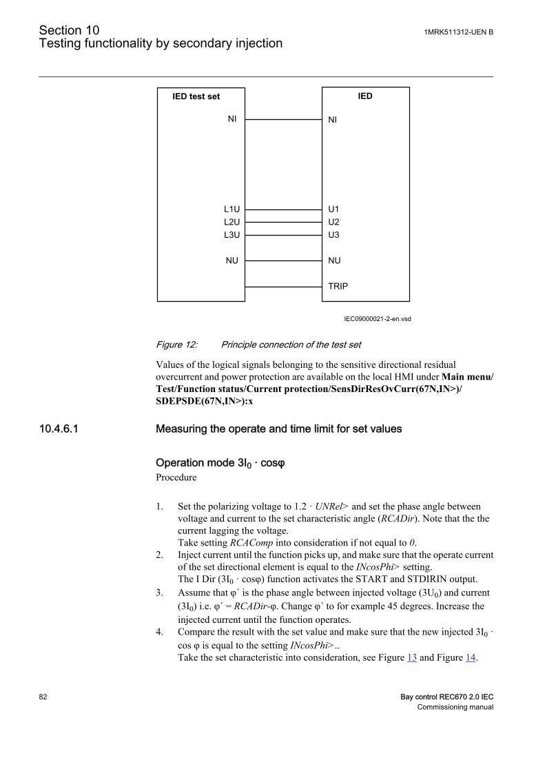
IEC09000021-2-en.vsd
IED test set
NI
IED
NI
L1UL2UL3U
NU
U1U2U3
NU
TRIP
IEC09000021 V2 EN
Figure 12: Principle connection of the test set
Values of the logical signals belonging to the sensitive directional residualovercurrent and power protection are available on the local HMI under Main menu/Test/Function status/Current protection/SensDirResOvCurr(67N,IN>)/SDEPSDE(67N,IN>):x
10.4.6.1 Measuring the operate and time limit for set values
Operation mode 3I0 · cosφProcedure
1. Set the polarizing voltage to 1.2 · UNRel> and set the phase angle betweenvoltage and current to the set characteristic angle (RCADir). Note that the thecurrent lagging the voltage.Take setting RCAComp into consideration if not equal to 0.
2. Inject current until the function picks up, and make sure that the operate currentof the set directional element is equal to the INcosPhi> setting.The I Dir (3I0 · cosφ) function activates the START and STDIRIN output.
3. Assume that φ´ is the phase angle between injected voltage (3U0) and current(3I0) i.e. φ´ = RCADir-φ. Change φ´ to for example 45 degrees. Increase theinjected current until the function operates.
4. Compare the result with the set value and make sure that the new injected 3I0 ·cos φ is equal to the setting INcosPhi>..Take the set characteristic into consideration, see Figure 13 and Figure 14.
Section 10 1MRK511312-UEN BTesting functionality by secondary injection
82 Bay control REC670 2.0 IECCommissioning manual
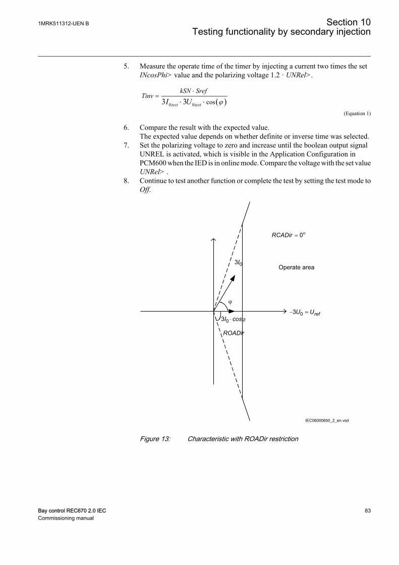
5. Measure the operate time of the timer by injecting a current two times the setINcosPhi> value and the polarizing voltage 1.2 · UNRel>.
( )0 0 cos3 3test test
kSN SrefTinv
I U j
×=
× ×IECEQUATION2402 V2 EN (Equation 1)
6. Compare the result with the expected value.The expected value depends on whether definite or inverse time was selected.
7. Set the polarizing voltage to zero and increase until the boolean output signalUNREL is activated, which is visible in the Application Configuration inPCM600 when the IED is in online mode. Compare the voltage with the set valueUNRel> .
8. Continue to test another function or complete the test by setting the test mode toOff.
Operate area
ROADir
IEC06000650_2_en.vsd
= o0RCADir
03I
j
03 × jI cos- =03 refU U
IEC06000650 V2 EN
Figure 13: Characteristic with ROADir restriction
1MRK511312-UEN B Section 10Testing functionality by secondary injection
Bay control REC670 2.0 IEC 83Commissioning manual

-3U0=U
ref
Operate area
Instrumenttransformerangle error
3I0
(prim)3I
0 (to prot)
Characteristic afterangle compensation
RCAcomp
IEC06000651-3-en.vsd
RCADir = 0º
IEC06000651 V3 EN
Figure 14: Explanation of RCAcomp
Operation mode 3I0 · 3U0 · cos φ
1. Set the polarizing voltage to 1.2 · UNRel> and set the phase angle betweenvoltage and current to the set characteristic angle (RCADir). Note that the currentlagging the voltage.
2. Inject current until the function picks up, and make sure that the operate poweris equal to the SN> setting for the set directional element.Note that for operation, both the injected current and voltage must be greaterthan the set values INRel> and UNRel> respectively.The function activates the START and STDIRIN outputs.
3. Assume that φ´ is the phase angle between injected voltage (3U0) and current(3I0) i.e. φ´ = RCADir-φ. Change φ´ to for example 45 degrees. Increase theinjected current until the function operates.
4. Compare the result with the set value and make sure that the new injected 3I0 ·3U0 · cos φ is equal to the setting SN>. Take the set characteristic intoconsideration, see figure 13 and figure 14.
Section 10 1MRK511312-UEN BTesting functionality by secondary injection
84 Bay control REC670 2.0 IECCommissioning manual
5. Measure the operate time of the timer by injecting 1.2 · UNRel> and a current toget two times the set SN> operate value.
( )0 0/ 3 3 costest testTinv kSN Sref I U j= × × ×
IECEQUATION2403 V1 EN (Equation 2)
6. Compare the result with the expected value.The expected value depends on whether definite or inverse time was selected.
7. Continue to test another function or complete the test by setting the test mode toOff.
Operation mode 3I0 and φ
1. Set the polarizing voltage to 1.2 · UNRel> and set the phase angle betweenvoltage and current to the set characteristic angle (RCADir). Note that the currentlagging the voltage.
2. Inject current until the function picks up, and make sure that the operate currentis equal to the INDir> setting for the set directional element.
Note that for operation, both the injected current and voltagemust be greater than the set values INRel> and UNRel>respectively.
The function activates the START and STDIRIN output.3. Measure with angles j around RCADir +/- ROADir.4. Compare the result with the set values, refer to figure 15 for example
characteristic.5. Measure the operate time of the timer by injecting a current to get two times the
set SN_> operate value.
( )0 0/ 3 3 costest testTinv kSN Sref I U j= × × ×
IECEQUATION2403 V1 EN (Equation 3)
6. Compare the result with the expected value.The expected value depends on whether definite or inverse time was selected.
7. Continue to test another function or complete the test by setting the test mode toOff.
1MRK511312-UEN B Section 10Testing functionality by secondary injection
Bay control REC670 2.0 IEC 85Commissioning manual

-3U0
Operate area
3I0
RCADir = 0º
ROADir = 80º
IEC06000652-3-en.vsdIEC06000652 V3 EN
Figure 15: Example characteristic
Non-directional earth fault current protectionProcedure
1. Measure that the operate current is equal to the INNonDir> setting.The function activates the START and STDIRIN output.
2. Measure the operate time of the timer by injecting a current of 200% of theoperate value.
3. Compare the result with the expected value.The expected value depends on whether definite time tINNonDir or inverse timewas selected.
4. Continue to test another function or complete the test by setting the test mode toOff.
Residual overvoltage release and protectionProcedure
1. Measure that the operate voltage is equal to the UN> setting.The function activates the START and STUN signals.
2. Measure the operate time by injecting a voltage 1.2 times set UN> operate value.3. Compare the result with the set tUN operate value.4. Inject a voltage 0.8 · UNRel> and a current high enough to operate the
directional function at the chosen angle.5. Increase the voltage until the directional function is released.6. Compare the measured value with the set UNRel> operate value.
Section 10 1MRK511312-UEN BTesting functionality by secondary injection
86 Bay control REC670 2.0 IECCommissioning manual
10.4.6.2 Completing the test
Continue to test another function or end the test by changing the TestMode setting toOff. Restore connections and settings to their original values, if they were changed fortesting purposes.
10.4.7 Thermal overload protection, one time constant, Celsius/Fahrenheit LCPTTR/LFPTTR
Prepare the IED for verification of settings outlined in section "Requirements" andsection "Preparing for test" in this chapter.
Check that the input logical signal BLOCK is logical zero and that on the local HMI,the logical signal TRIP, START and ALARM are equal to logical zero.
10.4.7.1 Measuring the operate and time limit of set values
Testing the protection without external temperature compensation(NonComp)
1. Quickly set the measured current (fault current) in one phase to about 300% ofIRef (to minimise the trip time), and switch the current off.
2. Reset the thermal memory on the local HMI under Main menu/Reset/Resettemperature/ThermalOverload1TimeConst(PTTR,26)/LFPTTR:x, Mainmenu/Reset/Reset temperature/ThermalOverload1TimeConst(PTTR,26)/LCPTTR:x,
3. Switch the fault current on and take note of the temperature, available on thelocal HMI under Main menu/Test/Function status/Current protection/ThermOverLoad1TimeConst(PTTR,26)/LFPTTR:x/TEMP, Main menu/Test/Function status/Current protection/ThermOverLoad1TimeConst(PTTR,26)/LCPTTR:x/TEMP,
4. Check the time until the actual temperature TEMP has reached the AlarmTemplevel during injection.Monitor the signal ALARM until it appears on the corresponding binary outputor on the local HMI.
5. Measure the LCPTTR/LFPTTRprotection trip time.Use the TRIP signal from the configured binary output to stop the timer.
6. Take the TEMP readings.Compare with the setting of TripTemp.
7. Activate the BLOCK binary input.The signals ALARM, START and TRIP should disappear.
8. Reset the BLOCK binary input.9. Check the reset limit (TdReset).
Monitor the signal START until it disappears on the corresponding binaryoutput or on the local HMI, take the TEMP readings and compare with thesetting of ReclTemp.
1MRK511312-UEN B Section 10Testing functionality by secondary injection
Bay control REC670 2.0 IEC 87Commissioning manual
10. Compare the measured trip time with the setting according to the formula.11. Reset the thermal memory.12. Continue to test another function or end the test by changing the test mode setting
to Off.
10.4.7.2 Completing the test
Continue to test another function or end the test by changing the TestMode setting toOff. Restore connections and settings to their original values, if they were changed fortesting purposes.
10.4.8 Thermal overload protection, two time constants TRPTTR
Prepare the IED for verification of settings outlined in section "Requirements" andsection "Preparing for test" in this chapter.
10.4.8.1 Checking operate and reset values
1. Connect symmetrical three-phase currents to the appropriate current terminalsof the IED.
2. Set the Time constant 1 (Tau1) and Time Constant 2 (Tau2) temporarily to 1minute.
3. Set the three-phase injection currents slightly lower than the set operate value ofstage IBase1, increase the current in phase L1 until stage IBase1 operates andnote the operate value.
Observe the maximum permitted overloading of the currentcircuits in the IED.
4. Decrease the current slowly and note the reset value.
Check, in the same way, the operate and reset values of IBase1 for phases L2 andL3.
5. Activate the cooling input signal, thus switching to base current IBase2.6. Check the operate and reset values (for all three phases) for IBase2 in the same
way as described above for stage IBase1.7. Deactivate the input signal for stage IBase2.8. Set the time constant for IBase1 in accordance with the setting plan.9. Set the injection current for phase L1 to 1.50 · IBase1.10. Connect a trip output contact to the timer and monitor the output of contacts
ALARM1 and ALARM2 to digital inputs in test equipment.Read the heat content in the thermal protection from the local HMI and wait untilthe content is zero.
Section 10 1MRK511312-UEN BTesting functionality by secondary injection
88 Bay control REC670 2.0 IECCommissioning manual
11. Switch on the injection current and check that ALARM1 and ALARM2 contactsoperate at the set percentage level and that the operate time for tripping is inaccordance with the set Time Constant 1 (Tau1).With setting Itr = 101%IBase1 and injection current 1.50 · IBase1, the trip timefrom zero content in the memory shall be 0.60 · Time Constant 1 (Tau1).
12. Check that all trip and alarm contacts operate according to the configurationlogic.
13. Switch off the injection current and check from the service menu readings ofthermal status and LOCKOUT that the lockout resets at the set percentage ofheat content.
14. Activate the cooling input signal to switch over to base current IBase2.Wait 5 minutes to empty the thermal memory and set Time Constant 2 (Tau2) inaccordance with the setting plan.
15. Test with injection current 1.50 · IBase2 the thermal alarm level, the operatetime for tripping and the lockout reset in the same way as described for stageIBase1.
16. Finally check that start and trip information is stored in the event menu.
10.4.8.2 Completing the test
Continue to test another function or end the test by changing the TestMode setting toOff. Restore connections and settings to their original values, if they were changed fortesting purposes.
10.4.9 Breaker failure protection, phase segregated activation andoutput CCRBRF
Prepare the IED for verification of settings outlined in section "Requirements" andsection "Preparing for test" in this chapter.
The Breaker failure protection, 3-phase activation and output function CCRBRFshould normally be tested in conjunction with some other function that provides a startsignal. An external START signal can also be used.
To verify the settings in the most common back-up trip mode 1 out of 3, it is sufficientto test phase-to-earth faults.
At mode 2 out of 4 the phase current setting, IP> can be checked by single-phaseinjection where the return current is connected to the summated current input. Thevalue of residual (earth fault) current IN set lower than IP> is easiest checked in back-up trip mode 1 out of 4.
10.4.9.1 Checking the phase current operate value, IP>
The check of the IP> current level is best made in FunctionMode = Current andBuTripMode = 1 out of 3 or 2 out of 4.
1MRK511312-UEN B Section 10Testing functionality by secondary injection
Bay control REC670 2.0 IEC 89Commissioning manual
1. Apply the fault condition, including START of CCRBRF, with a current belowset IP>.
2. Repeat the fault condition and increase the current in steps until a trip occurs.3. Compare the result with the set IP>.4. Disconnect AC and START input signals.
Note! If No CBPos Check or Retrip off is set, only back-up tripcan be used to check set IP>.
10.4.9.2 Checking the residual (earth fault) current operate value IN> set belowIP>
Check the low set IN> current where setting FunctionMode = Current and settingBuTripMode = 1 out of 4
1. Apply the fault condition, including START of CCRBRF, with a current justbelow set IN>.
2. Repeat the fault condition and increase the current in steps until trip appears.3. Compare the result with the set IN>.4. Disconnect AC and START input signals.
10.4.9.3 Checking the re-trip and back-up times
The check of the set times can be made in connection with the check of operate valuesabove.
Choose the applicable function and trip mode, such as FunctionMode = Current andRetripMode = CB Pos Check .
1. Apply the fault condition, including start of CCRBRF, well above the set currentvalue. Measure time from START of CCRBRF.
2. Check the re-trip t1 and back-up trip times t2 and t3.In applicable cases, the back-up trip for multi-phase start t2MPh and back-up trip2, t2 and t3 can also be checked. To check t2MPh, a two-phase or three-phasestart shall be applied.
3. Disconnect AC and START input signals.
10.4.9.4 Verifying the re-trip mode
Choose the mode below, which corresponds to the actual case.
In the cases below it is assumed that FunctionMode = Current is selected.
Checking the case without re-trip, RetripMode = Retrip Off
Section 10 1MRK511312-UEN BTesting functionality by secondary injection
90 Bay control REC670 2.0 IECCommissioning manual

1. Set RetripMode = Retrip Off.2. Apply the fault condition, including start of CCRBRF, well above the set current
value.3. Verify that no re-trip, but back-up trip is achieved after set time.
Checking the re-trip with current check, RetripMode = CB Pos Check
1. Set RetripMode = CB Pos Check.2. Apply the fault condition, including start of CCRBRF, well above the set current
value.3. Verify that re-trip is achieved after set time t1 and back-up trip after time t24. Apply the fault condition, including the start of CCRBRF, with the current
below the set current value.5. Verify that no re-trip, and no back-up trip is obtained.
Checking re-trip without current check
1. Set RetripMode = No CBPos Check.2. Apply the fault condition, including start of CCRBRF, well above the set current
value.3. Verify that re-trip is achieved after the set time t1, and the back-up trip after time
t2.4. Apply the fault condition, including start of CCRBRF, with current below set
current value.5. Verify that re-trip is achieved after set time t1, but no back-up trip is obtained.
10.4.9.5 Verifying the back-up trip mode
In the cases below it is assumed that FunctionMode = Current is selected.
Checking that back-up tripping is not achieved at normal CB trippingUse the actual tripping modes. The case below applies to re-trip with current check.
1. Apply the fault condition, including start of CCRBRF, with phase current wellabove set value IP>.
2. Interrupt the current, with a margin before back-up trip time, t2. It may be madeat issue of re-trip command.
3. Check that re-trip is achieved, if selected, but no back-up trip is obtained.
The normal mode BuTripMode = 1 out of 3 should have been verified in the testsabove. In applicable cases the modes 1 out of 4 and 2 out of 4 can be checked. Choosethe mode below, which corresponds to the actual case.
Checking the case BuTripMode = 1 out of 4It is assumed that the earth-fault current setting IN> is below phase current settingIP>.
1MRK511312-UEN B Section 10Testing functionality by secondary injection
Bay control REC670 2.0 IEC 91Commissioning manual
1. Set BuTripMode = 1 out of 4.2. Apply the fault condition, including start of CCRBRF, with one-phase current
below set IP> but above IN>. The residual earth-fault should then be above setIN>.
3. Verify that back-up trip is achieved after set time. If selected, re-trip should alsoappear.
4. Disconnect AC and START input signals.
Checking the case BuTripMode = 2 out of 4The earth-fault current setting IN> may be equal to or below phase-current settingIP>.
1. Set BuTripMode = 2 out of 4.2. Apply the fault condition, including start of CCRBRF, with one-phase current
above set IP> and residual (earth fault) above set IN>.3. Verify that back-up trip is achieved after set time. If selected, re-trip should also
appear.4. Apply the fault condition, including start of CCRBRF, with at least one-phase
current below set IP> and residual (earth fault) above set IN>. The current maybe arranged by feeding three- (or two-) phase currents with equal phase angle(I0-component) below IP>, but of such value that the residual (earth fault)current (3I0) will be above set value IN>.
5. Verify that back-up trip is not achieved.6. Disconnect AC and START input signals.
10.4.9.6 Verifying instantaneous back-up trip at CB faulty condition
Applies in a case where a signal from CB supervision function regarding CB beingfaulty and unable to trip is connected to input CBFLT.
1. Repeat the check of back-up trip time. Disconnect current and START inputsignals.
2. Activate the input CBFLT. The output CBALARM (CB faulty alarm) shouldappear after set time tCBAlarm. Keep the input activated.
3. Apply the fault condition, including start of CCRBRF, with current above setcurrent value.
4. Verify that back-up trip is obtained without intentional delay, for examplewithin 20ms from application of start.
10.4.9.7 Verifying the case RetripMode = Contact
It is assumed that re-trip without current check is selected, RetripMode = Contact.
Section 10 1MRK511312-UEN BTesting functionality by secondary injection
92 Bay control REC670 2.0 IECCommissioning manual
1. Set FunctionMode = Contact2. Apply input signal for CB closed to relevant input or inputs CBCLDL1,
CBCLD2 or CBCDL3.3. Apply the input signal, or signals for the start of CCRBRF.4. Verify that phase selection re-trip and back-up trip are achieved after set times.5. Disconnect the start signal(s). Keep the CB closed signal(s).6. Apply input signal(s), for start of CCRBRF.7.8. Arrange disconnection of CB closed signal(s) well before set back-up trip time
t2.9. Verify that back-up trip is not achieved.
10.4.9.8 Verifying the function mode Current&Contact
To be made only when FunctionMode = Current&Contact is selected. It is suggestedto make the tests in one phase only, or at three-phase trip applications for just three-phase tripping.
Checking the case with fault current above set value IP>The operation shall be as in FunctionMode = Current.
1. Set FunctionMode = Current&Contact.2. Leave the inputs for CB close inactivated. These signals should not influence.3. Apply the fault condition, including the start of CCRBRF, with the current above
the set IP> value.4. Check that the re-trip, if selected, and back-up trip commands are achieved.
Checking the case with fault current below set value I>BlkContThe case shall simulate a case where the fault current is very low and operation willdepend on CB position signal from CB auxiliary contact. It is suggested that re-tripwithout current check is used, setting RetripMode = No CBPos Check.
1. Set FunctionMode = Current&Contact.2. Apply input signal for CB closed to the relevant input or inputs CBCLDL1 (2 or
3).3. Apply the fault condition with input signal(s) for start of CCRBRF. The value of
current should be below the set value I>BlkCont.4. Verify that phase selection re-trip (if selected) and back-up trip are achieved
after set times. Failure to trip is simulated by keeping the signal(s) CB closedactivated.
5. Disconnect the input signal and the START signal(s). Keep the CB closedsignal(s).
1MRK511312-UEN B Section 10Testing functionality by secondary injection
Bay control REC670 2.0 IEC 93Commissioning manual
6. Apply the fault and the start again. The value of current should be below the setvalue I>BlkCont.
7. Arrange disconnection of BC closed signal(s) well before set back-up trip timet2. It simulates a correct CB tripping.
8. Verify that back-up trip is not achieved. Re-trip can appear for example, due toselection “Re-trip without current check”.
10.4.9.9 Completing the test
Continue to test another function or end the test by changing the TestMode setting toOff. Restore connections and settings to their original values, if they were changed fortesting purposes.
10.4.10 Stub protection STBPTOC
Prepare the IED for verification of settings outlined in section "Requirements" andsection "Preparing for test" in this chapter.
Logical signals for STBPTOC protection are available on the local HMI underMainmenu/Settings/Setting group N/Current protection/Stub(PTOC,50STB)/STBPTOC:x
10.4.10.1 Measuring the operate limit of set values
1. Check that the input logical signals BLOCK and RELEASE and the outputlogical signal TRIP are all logical zero.
2. Activate the input RELEASE on the STBPTOC function block3. For a short while inject a current (fault current) in one phase to about 110% of the
set operating current, and switch the current off.Observe to not exceed the maximum permitted overloading of the currentcircuits in the IED.
4. Switch the fault current on and measure the operating time of STBPTOC.Use the TRIP signal from the configured binary output to stop the timer. Theoperation should be instantaneously.
5. Activate the input BLOCK on the STBPTOC function block.6. Switch on the fault current (110% of the setting).
No TRIP signal should appear.7. Switch off the fault current.8. For a short while inject a current (fault current) in same phase to about 90% of
the set operating current, and switch the current off.9. Switch the fault current on.
No TRIP signal should appear.10. Switch off the fault current.11. Reset the RELEASE binary input.12. Switch the fault current on.
Section 10 1MRK511312-UEN BTesting functionality by secondary injection
94 Bay control REC670 2.0 IECCommissioning manual

No TRIP signal should appear.13. Switch the fault current off.
10.4.10.2 Completing the test
Continue to test another function or end the test by changing the TestMode setting toOff. Restore connections and settings to their original values, if they were changed fortesting purposes.
10.4.11 Pole discordance protection CCPDSC
Prepare the IED for verification of settings outlined in section "Requirements" andsection "Preparing for test" in this chapter.
10.4.11.1 Verifying the settings
1. External detection logic, Contact function selection = ContSel setting equalsCCPDSC signal from CB. Activate the EXTPDIND binary input, and measurethe operating time of CCPDSC.Use the TRIP signal from the configured binary output to stop the timer.
2. Compare the measured time with the set value tTrip.3. Reset the EXTPDIND input.4. Activate the BLKDBYAR binary input.
This test should be performed together with Autorecloser SMBRREC.5. Activate the EXTPDIND binary input.
No TRIP signal should appear.6. Reset both BLKDBYAR and EXTPDIND binary inputs.7. Activate the BLOCK binary input.8. Activate EXTPDIND binary input.
NO TRIP signal should appear.9. Reset both BLOCK and EXTPDIND binary inputs.10. If Internal detection logic Contact function selection = ContSel setting equals
Pole position from auxiliary contacts. Then set inputs POLE1OPN...POLE3CLin a status that activates the pole discordance logic and repeats step 2 to step 6.
11. Unsymmetrical current detection with CB monitoring: Set measured current inone phase to 110% of current release level. Activate CLOSECMD and measurethe operating time of the CCPDSC protection.Use the TRIP signal from the configured binary output to stop the timer.
12. Deactivate the CLOSECMD: Set measured current in one phase to 90% ofCurrent Release level. Activate CLOSECMD.NO TRIP signal should appear.
13. Repeat the previous two steps using OPENCMD instead of CLOSECMD.Asymmetry current detection with CB monitoring: Set all three currents to 110%of Current Release level. Activate CLOSECMD.
1MRK511312-UEN B Section 10Testing functionality by secondary injection
Bay control REC670 2.0 IEC 95Commissioning manual
NO TRIP signal should appear due to symmetrical condition.14. Deactivate the CLOSECMD. Decrease one current with 120% of the current
unsymmetrical level compared to the other two phases. Activate CLOSECMDand measure the operating time of the CCPDSC protection.Use the TRIP signal from the configured binary output to stop the timer.
15. Deactivate the CLOSECMD. Decrease one current with 80% of the currentunsymmetrical level compared to the other two phases. Activate CLOSECMD.NO TRIP signal should appear.
10.4.11.2 Completing the test
Continue to test another function or end the test by changing the TestMode setting toOff. Restore connections and settings to their original values, if they were changed fortesting purposes.
10.4.12 Directional underpower protection GUPPDUP
Prepare the IED for verification of settings outlined in section "Requirements" andsection "Preparing for test" in this chapter.
10.4.12.1 Verifying the settings
The underpower protection shall be set to values according to the real set values to beused.
The test is made by means of injection of voltage and current where the amplitude ofboth current and voltage and the phase angle between the voltage and current can becontrolled. During the test, the analog outputs of active and reactive power shall bemonitored.
1. Connect the test set for injection of voltage and current corresponding to themode to be used in the application. If a three-phase test set is available this couldbe used for all the modes. If a single-phase current/voltage test set is available thetest set should be connected to a selected input for one-phase current and voltage.
Section 10 1MRK511312-UEN BTesting functionality by secondary injection
96 Bay control REC670 2.0 IECCommissioning manual
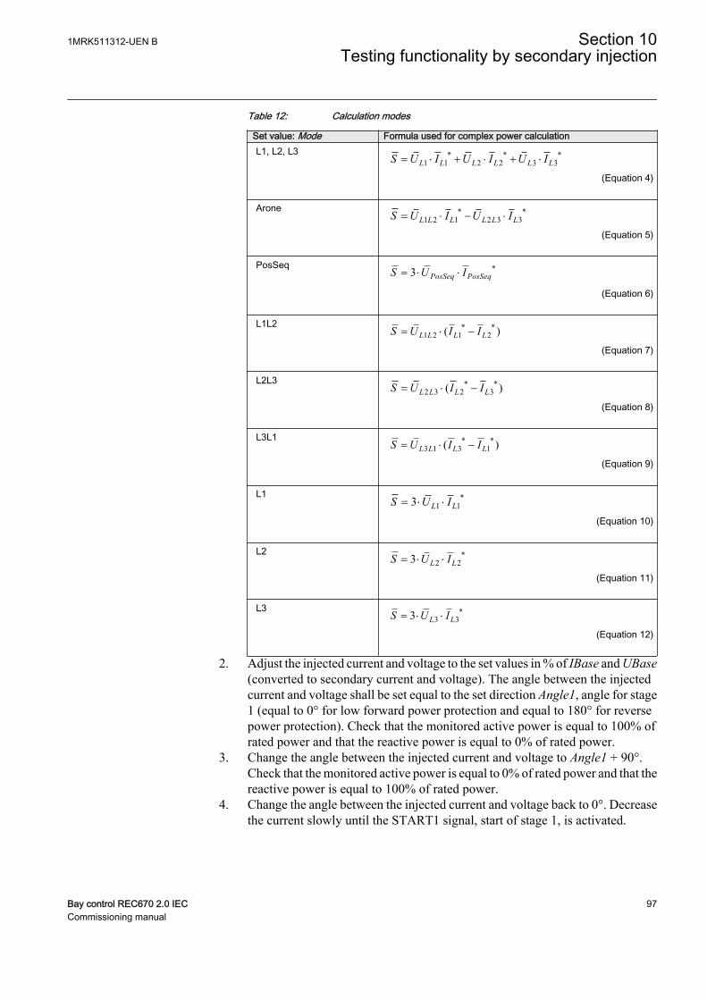
Table 12: Calculation modes
Set value: Mode Formula used for complex power calculationL1, L2, L3 * * *
1 1 2 2 3 3L L L L L LS U I U I U I= × + × + ×
EQUATION1697 V1 EN (Equation 4)
Arone * *1 2 1 2 3 3L L L L L LS U I U I= × - ×
EQUATION1698 V1 EN (Equation 5)
PosSeq *3 PosSeq PosSeqS U I= × ×
EQUATION1699 V1 EN (Equation 6)
L1L2 * *1 2 1 2( )L L L LS U I I= × -
EQUATION1700 V1 EN (Equation 7)
L2L3 * *2 3 2 3( )L L L LS U I I= × -
EQUATION1701 V1 EN (Equation 8)
L3L1 * *3 1 3 1( )L L L LS U I I= × -
EQUATION1702 V1 EN (Equation 9)
L1 *1 13 L LS U I= × ×
EQUATION1703 V1 EN (Equation 10)
L2 *2 23 L LS U I= × ×
EQUATION1704 V1 EN (Equation 11)
L3 *3 33 L LS U I= × ×
EQUATION1705 V1 EN (Equation 12)
2. Adjust the injected current and voltage to the set values in % of IBase and UBase(converted to secondary current and voltage). The angle between the injectedcurrent and voltage shall be set equal to the set direction Angle1, angle for stage1 (equal to 0° for low forward power protection and equal to 180° for reversepower protection). Check that the monitored active power is equal to 100% ofrated power and that the reactive power is equal to 0% of rated power.
3. Change the angle between the injected current and voltage to Angle1 + 90°.Check that the monitored active power is equal to 0% of rated power and that thereactive power is equal to 100% of rated power.
4. Change the angle between the injected current and voltage back to 0°. Decreasethe current slowly until the START1 signal, start of stage 1, is activated.
1MRK511312-UEN B Section 10Testing functionality by secondary injection
Bay control REC670 2.0 IEC 97Commissioning manual
5. Increase the current to 100% of IBase.6. Switch the current off and measure the time for activation of TRIP1, trip of stage
1.7. If a second stage is used, repeat steps 2 to 6 for the second stage.
10.4.12.2 Completing the test
Continue to test another function or end the test by changing the TestMode setting toOff. Restore connections and settings to their original values, if they were changed fortesting purposes.
10.4.13 Directional overpower protection GOPPDOP
Prepare the IED for verification of settings outlined in section "Requirements" andsection "Preparing for test" in this chapter.
10.4.13.1 Verifying the settings
The overpower protection shall be set to values according to the real set values to beused. The test is made by means of injection of voltage and current where theamplitude of both current and voltage and the phase angle between the voltage andcurrent can be controlled. During the test the analog outputs of active and reactivepower shall be monitored.
1. Connect the test set for injection of voltage and current corresponding to themode to be used in the application. If a three phase test set is available this couldbe used for all the modes. If a single phase current/voltage test set is available thetest set should be connected to a selected input for one phase current and voltage.
2. Adjust the injected current and voltage to the set rated values in % of IBase andUBase (converted to secondary current and voltage). The angle between theinjected current and voltage shall be set equal to the set direction Angle1, anglefor stage 1 (equal to 0° for low forward power protection and equal to 180° forreverse power protection). Check that the monitored active power is equal to100% of rated power and that the reactive power is equal to 0% of rated power.
3. Change the angle between the injected current and voltage to Angle1 + 90°.Check that the monitored active power is equal to 0% of rated power and that thereactive power is equal to 100% of rated power.
4. Change the angle between the injected current and voltage back to Angle1 value.Increase the current slowly from 0 until the START1 signal, start of stage 1, isactivated. Check the injected power and compare it to the set value Power1,power setting for stage 1 in % of Sbase.
5. Increase the current to 100% of IBase and switch the current off.6. Switch the current on and measure the time for activation of TRIP1, trip of stage
1.7. If a second stage is used, repeat steps 2 to 6 for the second stage.
Section 10 1MRK511312-UEN BTesting functionality by secondary injection
98 Bay control REC670 2.0 IECCommissioning manual
10.4.13.2 Completing the test
Continue to test another function or end the test by changing the TestMode setting toOff. Restore connections and settings to their original values, if they were changed fortesting purposes.
10.4.14 Broken conductor check BRCPTOC
Prepare the IED for verification of settings outlined in section "Requirements" andsection "Preparing for test" in this chapter.
10.4.14.1 Measuring the operate and time limit of set values
1. Check that the input logical signal BLOCK to the BRCPTOC function block islogical zero and note on the local HMI that the output signal TRIP from theBRCPTOC function block is equal to the logical 0.
2. Set the measured current (fault current) in one phase to about 110% of the setoperating current IP>.Observe to not exceed the maximum permitted overloading of the currentcircuits in the terminal.
3. Switch on the fault current and measure the operating time of BRCPTOC.TRIP is controlled by Gate 13 in the configuration.Use the TRIP signal from the configured binary output to stop the timer.
4. Compare the measured time with the set value tOper.5. Activate the BLOCK binary input.6. Switch on the fault current (110% of the setting) and wait longer than the set
value tOper.No TRIP signal should appear.
7. Switch off the fault current.8. Set the measured current (fault current) in same phase to about 90% of the set
operating current IP>. Switch off the current.9. Switch on the fault current and wait longer than the set value tOper.
No TRIP signal should appear.10. Switch off the fault current.
10.4.14.2 Completing the test
Continue to test another function or end the test by changing the TestMode setting toOff. Restore connections and settings to their original values, if they were changed fortesting purposes.
10.4.15 Capacitor bank protection CBPGAPC
Prepare the IED for verification of settings as outlined in section "Preparing for test"in this chapter.
1MRK511312-UEN B Section 10Testing functionality by secondary injection
Bay control REC670 2.0 IEC 99Commissioning manual
In this section it is shown how to test the capacitor bank protection functionCBPGAPC for application on a 50Hz, 200MVAr, 400kV SCB with 500/1A ratio CT.
Note that such SCB is shown in the application manual for thisfunction. The same procedure can be used to test SCB with some otherrating and different CT ratio.
As calculated in the application manual the base current for this particular SCB willbe 289A on the primary side and 0.578A on the CT secondary side. Before any testingis commenced make sure that setting IBase for this function is set to 289A (that is,setting for the base current corresponds to the rated current of the protected SCB). Itwill be also assumed that all other settings have values as shown in the setting examplein the application manual for this SCB.
Test equipment
Connect the secondary test set to the CT inputs on the IED dedicated for the SCBcurrents. Single- or three-phase test equipment can be used but it may be required tohave facility to vary the frequency of the injected current signal(s).
10.4.15.1 Verifying the settings and operation of the function
Reconnection inhibit feature
1. Inject SCB rated current (that is, 0.587A at 50Hz for this SCB) in at least onephase (preferably perform this test with three phase injection).
2. After couple of seconds stop injection of all currents (that is, set all currents backto 0A).
3. Check that function binary output signal RECNINH is set to logical 1 and thatonly resets after the set time under parameter tReconnInhibit (for example 300sfor this SCB) has expired.
4. If this binary signal is used to prevent CB closing make sure that it is properlyconnected/wired into the CB closing circuit.
Overcurrent feature
Note that during testing the overcurrent feature the harmonic voltageoverload feature or reactive power overload feature may also givestart and operate signals depending on their actual settings. Thereforeit is best to switch them off during this test.
Section 10 1MRK511312-UEN BTesting functionality by secondary injection
100 Bay control REC670 2.0 IECCommissioning manual

1. Inject current 20% bigger than the set overcurrent pickup level under settingparameter IOC> (for example, 1.2 · 1.35 · 0.587A = 0951A at 50Hz for thisSCB) in phase L1 only.
2. Check that function binary output signals STOCL1 and STOC are set to one.3. Check that function binary output signals TROC and TRIP are set to one after the
set time under parameter tOC (that is, 30s for this SCB) has expired.4. If any of these signals are used for tripping, signaling and/or local/remote
indication check that all relevant contacts and LEDs have operated and that allrelevant GOOSE messages have been sent.
5. Check that service value from the function for current in phase L1, on the localHMI under Main menu/Test is approximately 476A (that is, 0.951A · (500/1)= 476A).
6. Stop injection of all currents (that is, set all currents back to 0A).7. Check that all above mentioned function binary output signals now have logical
value zero.8. Repeat above steps 1-7 for phase L2 and phase L3.
Note that the operation of this feature is based on current peak value.That means that this overcurrent function is also able to operate for thesame current magnitude but for different injected frequencies. Ifrequired repeat this injection procedure for example for the 3rdharmonic by just simply injecting 3 · 50 = 150Hz currents with thesame magnitude. Obtain results shall be the same.
Undercurrent feature
1. Inject SCB rated current (that is, 0.587A at 50Hz for this SCB) in all threephases.
2. Lower phase L1 current 10% under the set value for setting parameter IUC<(that is, 0.9 · 0.7 · 0.587A = 0.370A at 50Hz for this SCB).
3. Check that function binary output signals STUCL1 and STUC are set to one.4. Check that function binary output signals TRUC and TRIP are set to one after the
set time under parameter tUC (for example, 5s for this SCB) has expired.5. If any of these signals are used for tripping, signaling and/or local/remote
indication check that all relevant contacts and LEDs have operated and that allrelevant GOOSE messages have been sent.
6. Check that service value from the function for current in phase L1, on the localHMI under Main menu/Test is approximately 185A (that is, 0.370A · (500/1)= 185A).
7. Stop injection of all currents (that is, set all currents back to 0A).8. Check that all above mentioned function binary output signals now have logical
value zero because they will be automatically blocked by operation of built-inreconnection inhibit feature.
9. Repeat above steps 1-8 for phase L2 and phase L3.
1MRK511312-UEN B Section 10Testing functionality by secondary injection
Bay control REC670 2.0 IEC 101Commissioning manual
Reactive power overload feature
Note that during testing the reactive power overload feature theharmonic voltage overload feature or overcurrent feature may alsogive start and operate signals depending on their actual settings.Therefore it is recommended to switch them off during this test.
1. Inject current equal to the set reactive power overload pickup level under settingparameter QOL> (that is, 1.3 · 0.587A = 0.763A at 50Hz for this SCB) in phaseL1 only.
2. Check that function binary output signals STQOLL1 and STQOL are set to one.3. Check that function binary output signals TRQOL and TRIP are set to one after
the set time under parameter tQOL (for example, 60s for this SCB) has expired.4. If any of these signals are used for tripping, signaling and/or local/remote
indication check that all relevant contacts and LEDs have operated and that allrelevant GOOSE messages have been sent.
5. Check that service value from the function for current in phase L1, on the localHMI under Main menu/Test is approximately 382A (that is, 0.763A · (500/1) =382A).
6. Check that service value from the function for reactive power in phase L1, on thelocal HMI under Main menu/Test is approximately 169% (that is, 1.3 · 1.3 =1,69pu = 169%).
7. Stop injection of all currents (that is, set all currents back to 0A).8. Check that all above mentioned function binary output signals now have logical
value zero.9. Repeat above steps 1 - 8 for phase L2 and phase L3.
Note that operation of this feature is based on injected current andinternally calculated true RMS values. That means that this feature isalso able to operate for current signals with varying frequency.However due to relatively complex calculation procedure it isrecommended to do secondary tests only with fundamental frequencycurrent signals.
The following formula can be used to calculate SCB reactive power in per-unit systemwhen current with different frequency from the rated frequency is injected.
[ ] [ ]2rated
injected
fQ pu I pu
f= ×
EQUATION2273 V1 EN (Equation 13)
Harmonic voltage overload feature
Section 10 1MRK511312-UEN BTesting functionality by secondary injection
102 Bay control REC670 2.0 IECCommissioning manual

Note that during testing the harmonic voltage overload feature thereactive power overload feature or overcurrent feature may also givestart and operate signals depending on their actual settings. Thereforeit is recommended to switch them off during this test.
Procedure to test inverse time delayed step:
The following points on the inverse curve are defined per relevant IEC/ANSIstandards for time multiplier value set to kHOLIDMT=1.0
UpeakRMS [pu] 1.15 1.2 1.3 1.4 1.7 2.0 2.2
Time [s] 1800 300 60 15 1 0.3 0.12
Note that operation of this feature is based on internally calculatedvoltage peak RMS value. That means that this feature is also able tooperate for current signals with varying frequency.
Here will be shown how to test the fourth point from the above table. Other points canbe tested in the similar way:
1. Inject 140% of the base current (that is, 1.4 · 0.587A = 0.822A at 50Hz for thisSCB) in phase L1only.
2. Check that function binary output signals STHIDML1 and STHOL are set toone.
3. Check that function binary output signals TRHOL and TRIP are set to one afterthe expected time (for example, 15s for this voltage level in accordance with theabove table) has expired.
4. If any of these signals are used for tripping, signaling and/or local/remoteindication, check that all relevant contacts and LEDs have operated and that allrelevant GOOSE messages have been sent.
5. Check that service value for current in phase L1, on the local HMI under Mainmenu/Test is approximately 411A (that is, 0.822A · (500/1) = 411A).
6. Check that service value for voltage across SCB in phase L1, on the local HMIunder Main menu/Test is approximately 140%.
7. Stop injection of all currents (that is, set all currents back to 0A).8. Check that all above mentioned function binary output signals now have logical
value zero.9. Repeat above steps 1 - 8 for phase L2 and phase L3.10. Repeat above steps 1 - 8 to test different points from the above table.
Operation of this feature is based on internally calculated peak RMS voltage value.That means that this feature is also able to operate for current signals with varyingfrequency. Note that for the fundamental frequency injection, internally calculatedvoltage in percent corresponds directly to the injected current value given in percent.However if it is required to test IDMT characteristic with a varying frequency, the
1MRK511312-UEN B Section 10Testing functionality by secondary injection
Bay control REC670 2.0 IEC 103Commissioning manual

magnitude of the injected current must be adjusted accordingly. The followingformula can be used to calculate required current RMS value in percent at the desiredinjection frequency in order to archive voltage percentage value given in the abovetable:
[ ] [ ]% %injected
rated
inj
fI U
f= ×
EQUATION2274 V1 EN (Equation 14)
Note that it is recommended to test IDMT operating times by injectedcurrent with the rated frequency.
Above procedure can also be used to test definite time step. Pay attention that IDMTstep can also operate during such injection. Therefore make sure that appropriatesettings are entered in order to insure correct test results for definite time step.
10.4.15.2 Completing the test
Continue to test another functions or end the test by changing the Test mode setting toOff. Restore connections and settings to their original values, if they were changed fortesting purposes. Make sure that all built-in features for this function, which shall bein operation, are enabled and with correct settings.
10.4.16 Voltage-restrained time overcurrent protection VRPVOC
Prepare the IED for verification of settings outlined in section "Requirements" andsection "Preparing for test" in this chapter.
10.4.16.1 Verifying the settings
Verifying settings by secondary injection
1. Connect the test set for three-phase current injection and three-phase voltageinjection to the appropriate IED terminals.
2. Go to Main menu/Settings/IED Settings/Current protection/VoltageRestOverCurr ( 51V,2(I>/U<))/VRPVOC (51V,2(I>/U<)):1/General and make sure that the function is enabled, that is, Operation is set toOn.
3. The test of the function may be performed by injecting restrain voltage andincreasing the injected current(s). Note the value at which the START and STOCsignals are set.
In the following equations, restrain voltage is the magnitude ofthe minimum phase-to-phase voltage in secondary volts.
Section 10 1MRK511312-UEN BTesting functionality by secondary injection
104 Bay control REC670 2.0 IECCommissioning manual
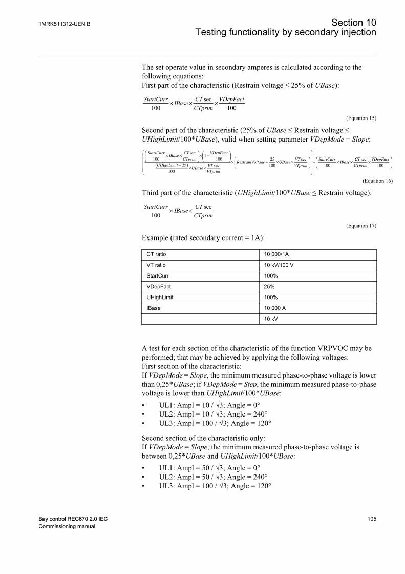
The set operate value in secondary amperes is calculated according to thefollowing equations:First part of the characteristic (Restrain voltage ≤ 25% of UBase):
StartCurrIBase
CT
CTprim
VDepFact
100 100× × ×
sec
IECEQUATION2432 V1 EN (Equation 15)
Second part of the characteristic (25% of UBase ≤ Restrain voltage ≤UHighLimit/100*UBase), valid when setting parameter VDepMode = Slope:
StartCurrIBase
CT
CTprim
VDepFact
UH
1001
100× ×
× −
sec
iighLimitUBase
VT
VTprim
strainVoltage−( )
× ×
× − ×
25
100
25
100secRe UUBase
VT
VTprim
StartCurrIBase×
+ × ×sec
100
CCT
CTprim
VDepFactsec×
100
IECEQUATION2433 V1 EN (Equation 16)
Third part of the characteristic (UHighLimit/100*UBase ≤ Restrain voltage):
StartCurrIBase
CT
CTprim100× ×
sec
IECEQUATION2434 V1 EN (Equation 17)
Example (rated secondary current = 1A):
CT ratio 10 000/1A
VT ratio 10 kV/100 V
StartCurr 100%
VDepFact 25%
UHighLimit 100%
IBase 10 000 A
10 kV
A test for each section of the characteristic of the function VRPVOC may beperformed; that may be achieved by applying the following voltages:First section of the characteristic:If VDepMode = Slope, the minimum measured phase-to-phase voltage is lowerthan 0,25*UBase; if VDepMode = Step, the minimum measured phase-to-phasevoltage is lower than UHighLimit/100*UBase:• UL1: Ampl = 10 / √3; Angle = 0°• UL2: Ampl = 10 / √3; Angle = 240°• UL3: Ampl = 100 / √3; Angle = 120°
Second section of the characteristic only:If VDepMode = Slope, the minimum measured phase-to-phase voltage isbetween 0,25*UBase and UHighLimit/100*UBase:• UL1: Ampl = 50 / √3; Angle = 0°• UL2: Ampl = 50 / √3; Angle = 240°• UL3: Ampl = 100 / √3; Angle = 120°
1MRK511312-UEN B Section 10Testing functionality by secondary injection
Bay control REC670 2.0 IEC 105Commissioning manual
Last section of the characteristic:If VDepMode = either Slope or Step, the minimum measured phase-to-phasevoltage is higher than UHighLimit/100*UBase:• UL1: Ampl = 105/ √3; Angle = 0°• UL2: Ampl = 105/ √3; Angle = 240°• UL3: Ampl = 105 / √3; Angle = 120°
4. Inject the voltages that are related to the first part of the characteristic, and thenslowly increase the phase current IL1 from 0.0 A up to the value the functionoperates. The START and STOC signals must be activated when the amplitudeof the phase current IL1 is slightly above 0.25 A on the secondary side. Thecorresponding trip signals TROC and TRIP will be activated after the pre-settime delay has expired.
5. Decrease the current IL1 slowly and note the reset value.6. Repeat steps 4 and 5 applying voltages that are related to the second and the last
section of the characteristic; the function operates when IL1 is slightly higherthan: 0.5 A in the second section; 1A in the last section.
7. Connect the trip output contact to the input channel of the test set in order to stopthe injection and measure the trip time.
8. If definite time delay is used for the overcurrent step, set the setting Characterist= IEC Def. Time. Apply the voltages related to the last part of the characteristicand inject a current IL1 200% higher than the set operation level, and check thedefinite time delay for trip (the signals TROC and TRIP of the protectionfunction VRPVOC are active in trip condition).
9. If inverse time delay is used for the overcurrent step, the parameter settingCharacterist shall be properly set; we can refer, for example, to the setting IECVery inv.; If the IEC Very inverse time characteristic is selected, the trip signalsTROC and TRIP will operate after a time defined by the equation:
t sk
I
StartCurr
[ ] =
−
13 5
1
. *
IECEQUATION2435 V1 EN (Equation 18)
where:
t Operate time in seconds
I Measured value (for example, phase current)
StartCurr Set operate value
This means that if the measured phase current jumps from 0 to 2 times the setoperate level and time multiplier k is set to 1.0 s (default value), then the TROCand TRIP signals will operate after a time delay equal to 13.5 s ± tolerance.Taking into account the above explanation, inject the voltages related to the lastpart of the characteristic and inject a current IL1 200% higher than the setoperation level, and check the trip time delay.
Section 10 1MRK511312-UEN BTesting functionality by secondary injection
106 Bay control REC670 2.0 IECCommissioning manual
If tDef_OC is set to a value different from 0 s, then this timedelay is added to the one that is defined by the IDMTcharacteristic.
10. Check the start and operate information that are stored in the event menu.11. The previous step 8 or 9 may be repeated also for the first and second section of
the characteristic.12. Supply the IED with symmetric three-phase voltages at their rated values. Go to
Main menu/Settings/IED Settings/Current protection/VoltageRestOverCurr(51V,2(I>/U<))/VRPVOC(51V,2(I>/U<)):1/Undervoltage and set the setting Operation_UV = On to activate theundervoltage stage.
13. Slowly decrease the voltage in two phases simultaneously, until the STUV andSTART signals appear.
14. Note the operate value. The set operate value in secondary volts is calculatedaccording to the following equation:
StartVolt UBase VT
VTprim100 3× ×
sec
IECEQUATION2436 V1 EN (Equation 19)
If the VRPVOC function is used as an overcurrent protectionwith undervoltage seal-in, it is necessary to first inject sufficientcurrent to activate the STOC signal before the under-voltagestep is allowed to operate. In order to achieve that, applysymmetric three-phase voltages at their rated value and theninject a current IL1 that is 200% higher than the set operationlevel. Then slowly decrease the voltage in two phasessimultaneously, until the STUV and START signals appear.
15. Increase slowly the applied voltages of the previous two phases and note thereset value.
16. Check that the trip output of the relay is connected to the input channel of the testin order to stop the injection and measure the trip time.
17. Inject symmetric three-phase voltages at their rated value and check that theSTUV and START signals reset as well as the trip signals of the function block(TRIP and TRUV).
18. Instantaneously decrease the voltage in two phases simultaneously to a value20% lower than the set operate value (take into account the previous note ifVRPVOC is configured in ACT with the undervoltage seal-in feature).
19. Measure the definite time delay for the TRUV and TRIP signals and compare itwith the set value tDef_UV.
20. Check that start and operate information is stored in the event menu.
1MRK511312-UEN B Section 10Testing functionality by secondary injection
Bay control REC670 2.0 IEC 107Commissioning manual
10.4.16.2 Completing the test
Continue to test another function or end the test by changing the TestMode setting toOff. Restore connections and settings to their original values, if they were changed fortesting purposes.
10.5 Voltage protection
10.5.1 Two step undervoltage protection UV2PTUV
Prepare the IED for verification of settings outlined in section "Requirements" andsection "Preparing for test" in this chapter.
10.5.1.1 Verifying the settings
Verification of START value and time delay to operate for Step 1
1. Check that the IED settings are appropriate, especially the START value, thedefinite time delay and the 1 out of 3 operation mode.
2. Supply the IED with three-phase voltages at their rated values.3. Slowly decrease the voltage in one of the phases, until the START signal
appears.4. Note the operate value and compare it with the set value.
The operate value in secondary volts is calculated according tothe following equations:
For phase-to-earth measurement:
U UBase VT
VTprim
1
100 3
<× ×
sec
IECEQUATION2430 V1 EN (Equation 20)
For phase-to-phase measurement:
UUBase
VT
VTprim
1
100
<× ×
sec
IECEQUATION2431 V1 EN (Equation 21)5. Increase the measured voltage to rated load conditions.6. Check that the START signal resets.7. Instantaneously decrease the voltage in one phase to a value about 20% lower
than the measured operate value.8. Measure the time delay for the TRIP signal, and compare it with the set value.9. Check the inverse time delay by injecting a voltage corresponding to 0.8 × U1<.
Section 10 1MRK511312-UEN BTesting functionality by secondary injection
108 Bay control REC670 2.0 IECCommissioning manual

For example, if the inverse time curve A is selected, the tripsignals TR1 and TRIP operate after a time corresponding to theequation:
t sk
U
U
( ) =
−
<
1
11
IECEQUATION2428 V1 EN (Equation 22)
where:
t(s) Operate time in seconds
k1 Settable time multiplier of the function for step 1
U Measured voltage
U1< Set start voltage for step 1
For example, if the measured voltage jumps from the rated value to 0.8 times theset start voltage level and time multiplier k1 is set to 0.05 s (default value), thenthe TR1 and TRIP signals operate at a time equal to 0.250 s ± tolerance.
10. The test above can be repeated to check the inverse time characteristic atdifferent voltage levels.
11. Repeat the above-described steps for Step 2 of the function.
Extended testingThe tests above can be repeated for 2 out of 3 and for 3 out of 3 operation mode.
10.5.1.2 Completing the test
Continue to test another function or end the test by changing the TestMode setting toOff. Restore connections and settings to their original values, if they were changed fortesting purposes.
10.5.2 Two step overvoltage protection OV2PTOV
Prepare the IED for verification of settings outlined in section "Requirements" andsection "Preparing for test" in this chapter.
10.5.2.1 Verifying the settings
Verification of single-phase voltage and time delay to operate for Step1
1. Apply single-phase voltage below the set value U1>.2. Slowly increase the voltage until the ST1 signal appears.3. Note the operate value and compare it with the set value U1>.
1MRK511312-UEN B Section 10Testing functionality by secondary injection
Bay control REC670 2.0 IEC 109Commissioning manual
The operate value in secondary volts is calculated according tothe following equations:
For phase-to-earth measurement:
U UBase VT
VTprim
1
100 3
>× ×
sec
IECEQUATION2426 V1 EN (Equation 23)
For phase-to-phase measurement:
UUBase
VT
VTprim
1
100
>× ×
sec
IECEQUATION2427 V1 EN (Equation 24)4. Decrease the voltage slowly and note the reset value.5. Set and apply about 20% higher voltage than the measured operate value for one
phase.6. Measure the time delay for the TR1 signal and compare it with the set value.7. Check the inverse time delay by injecting a voltage corresponding to 1.2 × U1>.8. Repeat the test to check the inverse time characteristic at different over-voltage
levels.9. Repeat the above-described steps for Step 2 of the function.
10.5.2.2 Extended testing
1. The tests above can be repeated for 2 out of 3 and for 3 out of 3 operation mode.
10.5.2.3 Completing the test
Continue to test another function or end the test by changing the TestMode setting toOff. Restore connections and settings to their original values, if they were changed fortesting purposes.
10.5.3 Two step residual overvoltage protection ROV2PTOV
Prepare the IED for verification of settings outlined in section "Requirements" andsection "Preparing for test" in this chapter.
10.5.3.1 Verifying the settings
1. Apply the single-phase voltage either to a single-phase voltage input or to aresidual voltage input with the start value below the set value U1>.
2. Slowly increase the value until ST1 appears.3. Note the operate value and compare it with the set value.
Section 10 1MRK511312-UEN BTesting functionality by secondary injection
110 Bay control REC670 2.0 IECCommissioning manual

4. Decrease the voltage slowly and note the reset value.5. Set and apply about 20% higher voltage than the measured operate value for one
phase.6. Measure the time delay for the TR1 signal and compare it with the set value.7. Check the inverse time delay by injecting a voltage corresponding to 1.2 × U1>.
For example, if the inverse time curve A is selected, the tripsignals TR1 and TRIP operate after a time corresponding to theequation:
t sk
U
U
( ) =
>
−
1
11
IECEQUATION2429 V1 EN (Equation 25)
where:
t(s) Operate time in seconds
k1 Settable time multiplier of the function for step 1
U Measured voltage
U1> Set start voltage for step 1
For example, if the measured voltage jumps from 0 to 1.2 times the set startvoltage level and time multiplier k1 is set to 0.05 s (default value), then the TR1and TRIP signals operate at a time equal to 0.250 s ± tolerance.
8. Repeat the test for Step 2 of the function.
10.5.3.2 Completing the test
Continue to test another function or end the test by changing the TestMode setting toOff. Restore connections and settings to their original values, if they were changed fortesting purposes.
10.5.4 Voltage differential protection VDCPTOV
Prepare the IED for verification of settings as outlined in section "Requirements" andsection "Preparing for test" in this chapter.
10.5.4.1 Check of undervoltage levels
This test is relevant if the setting BlkDiffAtULow = Yes.
Check of U1LowProcedure
1MRK511312-UEN B Section 10Testing functionality by secondary injection
Bay control REC670 2.0 IEC 111Commissioning manual
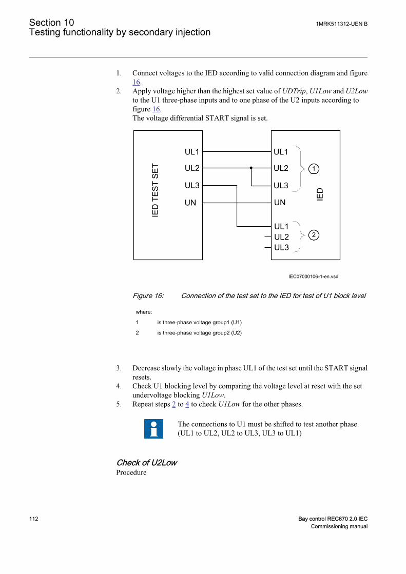
1. Connect voltages to the IED according to valid connection diagram and figure16.
2. Apply voltage higher than the highest set value of UDTrip, U1Low and U2Lowto the U1 three-phase inputs and to one phase of the U2 inputs according tofigure 16.The voltage differential START signal is set.
UL1
UL2
UL3
UN
UL1
UL1UL2UL3
IED
TE
ST
SE
T
IED
IEC07000106-1-en.vsd
UL2
UL3
UN
1
2
IEC07000106 V2 EN
Figure 16: Connection of the test set to the IED for test of U1 block level
where:
1 is three-phase voltage group1 (U1)
2 is three-phase voltage group2 (U2)
3. Decrease slowly the voltage in phase UL1 of the test set until the START signalresets.
4. Check U1 blocking level by comparing the voltage level at reset with the setundervoltage blocking U1Low.
5. Repeat steps 2 to 4 to check U1Low for the other phases.
The connections to U1 must be shifted to test another phase.(UL1 to UL2, UL2 to UL3, UL3 to UL1)
Check of U2LowProcedure
Section 10 1MRK511312-UEN BTesting functionality by secondary injection
112 Bay control REC670 2.0 IECCommissioning manual
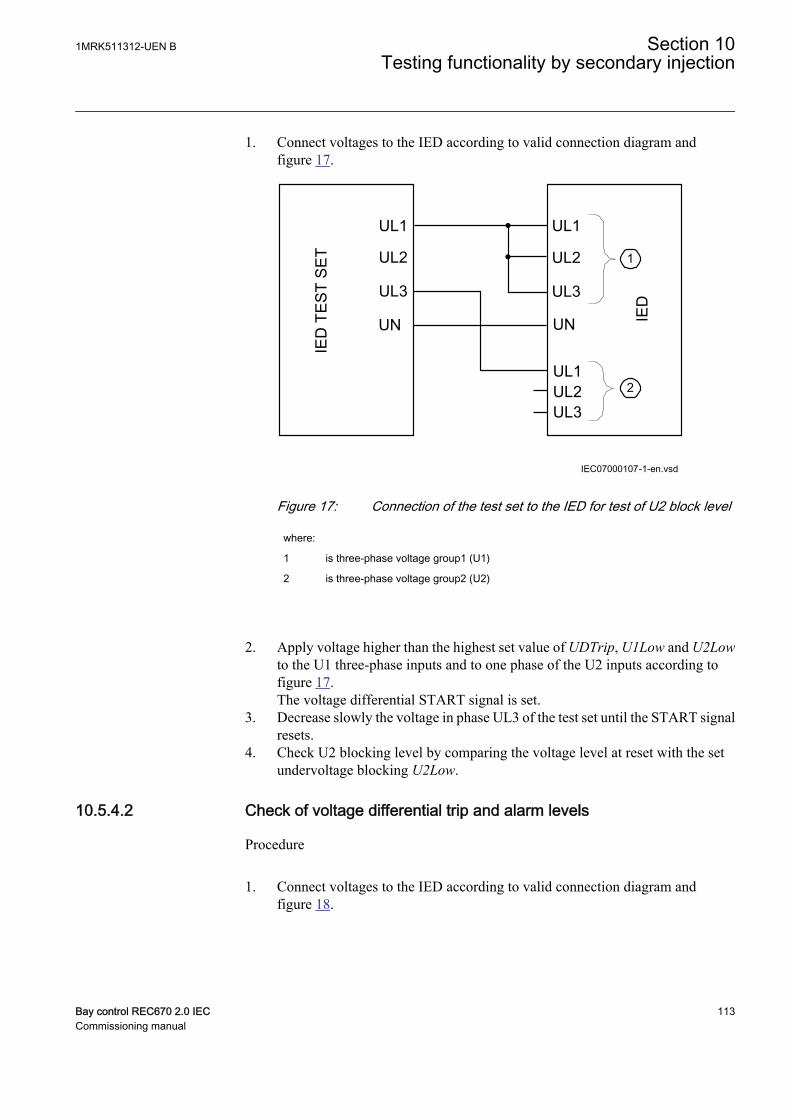
1. Connect voltages to the IED according to valid connection diagram andfigure 17.
UL1
UL2
UL3
UN
UL1
UL1UL2UL3
IED
TE
ST
SE
T
IED
IEC07000107-1-en.vsd
UL2
UL3
UN
1
2
IEC07000107 V2 EN
Figure 17: Connection of the test set to the IED for test of U2 block level
where:
1 is three-phase voltage group1 (U1)
2 is three-phase voltage group2 (U2)
2. Apply voltage higher than the highest set value of UDTrip, U1Low and U2Lowto the U1 three-phase inputs and to one phase of the U2 inputs according tofigure 17.The voltage differential START signal is set.
3. Decrease slowly the voltage in phase UL3 of the test set until the START signalresets.
4. Check U2 blocking level by comparing the voltage level at reset with the setundervoltage blocking U2Low.
10.5.4.2 Check of voltage differential trip and alarm levels
Procedure
1. Connect voltages to the IED according to valid connection diagram andfigure 18.
1MRK511312-UEN B Section 10Testing functionality by secondary injection
Bay control REC670 2.0 IEC 113Commissioning manual

UL1
UL2
UL3
UN
UL1
UL1UL2UL3
IED
TE
ST
SE
T
IED
IEC07000108-1-en.vsd
UL2
UL3
UN
1
2
IEC07000108 V2 EN
Figure 18: Connection of the test set to the IED for test of alarm levels, triplevels and trip timer
where:
1 is three-phase voltage group1 (U1)
2 is three-phase voltage group2 (U2)
2. Apply 1.2 · Ur (rated voltage) to the U1 and U2 inputs.3. Decrease slowly the voltage of in phase UL1 of the test set until the ALARM
signal is activated.
The ALARM signal is delayed with timer tAlarm
4. Check the alarm operation level by comparing the differential voltage level atALARM with the set alarm level UDAlarm.
5. Continue to slowly decrease the voltage until START signal is activated.6. Check the differential voltage operation level by comparing the differential
voltage level at START with the set trip level UDTrip.7. Repeat steps 1 to 6 to check the other phases.
Observe that the connections to U1 must be shifted to test another phase. (UL1to UL2, UL2 to UL3, UL3 to UL1)
10.5.4.3 Check of trip and trip reset timers
Procdure
Section 10 1MRK511312-UEN BTesting functionality by secondary injection
114 Bay control REC670 2.0 IECCommissioning manual
1. Connect voltages to the IED according to valid connection diagram and figure18.
2. Set Ur (rated voltage) to the U1 inputs and increase U2 voltage until differentialvoltage is 1.5 · operating level (UDTrip).
3. Switch on the test set. Measure the time from activation of the START signaluntil TRIP signal is activated.
4. Check the measured time by comparing it to the set trip time tTrip.5. Increase the voltage until START signal resets. Measure the time from reset of
START signal to reset of TRIP signal.6. Check the measured time by comparing it to the set trip reset time tReset.
10.5.4.4 Final adjustment of compensation for VT ratio differences
Procedure
1. With the protection in test mode, view the differential voltage service values ineach phase on the local HMI under Main menu/Test/Function status/Voltageprotection/VoltageDiff(PTOV,60)/VDCPTOV:x.
The IED voltage inputs should be connected to the VTsaccording to valid connection diagram.
2. Record the differential voltages.3. Calculate the compensation factor RFLx for each phase.
For information about calculation of the compensation factor, see theapplication manual.
4. Set the compensation factors on the local HMI under Main menu/Settings/Settings group N/Voltage protection/VoltageDiff(PTOV,60)/VDCPTOV:x
5. Check that the differential voltages are close to zero.
10.5.4.5 Completing the test
Continue to test another function or end the test by changing the TestMode setting toOff. Restore connections and settings to their original values, if they were changed fortesting purposes.
10.5.5 Loss of voltage check LOVPTUV
Prepare the IED for verification of settings outlined in section "Requirements" andsection "Preparing for test" in this chapter.
10.5.5.1 Measuring the operate limit of set values
1MRK511312-UEN B Section 10Testing functionality by secondary injection
Bay control REC670 2.0 IEC 115Commissioning manual
1. Check that the input logical signals BLOCK, CBOPEN and VTSU are logicalzero.
2. Supply a three-phase rated voltage in all three phases and note on the local HMIthat the TRIP logical signal is equal to the logical 0.
3. Switch off the voltage in all three phases.After set tTrip time a TRIP signal appears on the corresponding binary output oron the local HMI.
Note that TRIP at this time is a pulse signal, duration should beaccording to set tPulse.
4. Inject the measured voltages at rated values for at least set tRestore time.5. Activate the CBOPEN binary input.6. Simultaneously disconnect all the three-phase voltages from the IED.
No TRIP signal should appear.7. Inject the measured voltages at rated values for at least set tRestore time.8. Activate the VTSU binary input.9. Simultaneously disconnect all the three-phase voltages from the IED.
No TRIP signal should appear.10. Reset the VTSU binary input.11. Inject the measured voltages at rated values for at least set tRestore time.12. Activate the BLOCK binary input.13. Simultaneously disconnect all the three-phase voltages from the IED.
No TRIP signal should appear.14. Reset the BLOCK binary input.
10.5.5.2 Completing the test
Continue to test another function or end the test by changing the TestMode setting toOff. Restore connections and settings to their original values, if they were changed fortesting purposes.
10.6 Frequency protection
10.6.1 Underfrequency protection SAPTUF
Prepare the IED for verification of settings outlined in section "Requirements" andsection "Preparing for test" in this chapter.
10.6.1.1 Verifying the settings
Verification of START value and time delay to operate
Section 10 1MRK511312-UEN BTesting functionality by secondary injection
116 Bay control REC670 2.0 IECCommissioning manual
1. Check that the IED settings are appropriate, for example the START value andthe time delay.
2. Supply the IED with three-phase voltages at their rated values.3. Slowly decrease the frequency of the applied voltage, until the START signal
appears.4. Note the operate value and compare it with the set value.5. Increase the frequency until rated operating levels are reached.6. Check that the START signal resets.7. Instantaneously decrease the frequency of the applied voltage to a value about
1% lower than the operate value (a step change more than 2% will increase thetime delay).
8. Measure the time delay of the TRIP signal, and compare it with the set value.Note that the measured time consists of the set value for time delay plusminimum operate time of the start function (80 - 90 ms).
Extended testing
1. The test above can be repeated to check the time to reset.2. The tests above can be repeated to test the frequency dependent inverse time
characteristic.
Verification of the low voltage magnitude blocking
1. Check that the IED settings are appropriate, for example the StartFrequency,UMin , and the tDelay.
2. Supply the IED with three-phase voltages at rated values.3. Slowly decrease the magnitude of the applied voltage, until the BLKDMAGN
signal appears.4. Note the voltage magnitude value and compare it with the set value UMin.5. Slowly decrease the frequency of the applied voltage, to a value below
StartFrequency.6. Check that the START signal does not appear.7. Wait for a time corresponding to tDelay, make sure that the TRIP signal does not
appear.
10.6.1.2 Completing the test
Continue to test another function or end the test by changing the TestMode setting toOff. Restore connections and settings to their original values, if they were changed fortesting purposes.
10.6.2 Overfrequency protection SAPTOF
Prepare the IED for verification of settings outlined in section "Requirements" andsection "Preparing for test" in this chapter.
1MRK511312-UEN B Section 10Testing functionality by secondary injection
Bay control REC670 2.0 IEC 117Commissioning manual

10.6.2.1 Verifying the settings
Verification of START value and time delay to operate
1. Check that the settings in the IED are appropriate, for example the START valueand the time delay.
2. Supply the IED with three-phase voltages at their rated values.3. Slowly increase the frequency of the applied voltage, until the START signal
appears.4. Note the operate value and compare it with the set value.5. Decrease the frequency to rated operating conditions.6. Check that the START signal resets.7. Instantaneously increase the frequency of the applied voltage to a value about
1% lower than the operate value (a step change more than 2% will increase thetime delay).
8. Measure the time delay for the TRIP signal, and compare it with the set value.Note that the measured time consists of the set value for time delay plusminimum operate time of the start function (80 - 90 ms).
Extended testing
1. The test above can be repeated to check the time to reset.
Verification of the low voltage magnitude blocking
1. Check that the settings in the IED are appropriate, for example theStartFrequency, UMin, and the tDelay.
2. Supply the IED with three-phase voltages at their rated values.3. Slowly decrease the magnitude of the applied voltage, until the BLKDMAGN
signal appears.4. Note the voltage magnitude value and compare it with the set value, UMin.5. Slowly increase the frequency of the applied voltage, to a value above
StartFrequency.6. Check that the START signal does not appear.7. Wait for a time corresponding to tDelay, make sure that the TRIP signal does not
appear.
10.6.2.2 Completing the test
Continue to test another function or end the test by changing the TestMode setting toOff. Restore connections and settings to their original values, if they were changed fortesting purposes.
Section 10 1MRK511312-UEN BTesting functionality by secondary injection
118 Bay control REC670 2.0 IECCommissioning manual
10.6.3 Rate-of-change frequency protection SAPFRC
Prepare the IED for verification of settings outlined in section "Requirements" andsection "Preparing for test" in this chapter.
10.6.3.1 Verifying the settings
Verification of START value and time delay to operate
1. Check that the settings in the IED are appropriate, especially the START valueand the definite time delay. Set StartFreqGrad, to a rather small negative value.
2. Supply the IED with three-phase voltages at their rated values.3. Slowly decrease the frequency of the applied voltage, with an increasing rate-of-
change that finally exceeds the setting of StartFreqGrad, and check that theSTART signal appears.
4. Note the operate value and compare it with the set value.5. Increase the frequency to rated operating conditions, and zero rate-of-change.6. Check that the START signal resets.7. Instantaneously decrease the frequency of the applied voltage to a value about
20% lower than the nominal value.8. Measure the time delay for the TRIP signal, and compare it with the set value.
Extended testing
1. The test above can be repeated to check a positive setting of StartFreqGrad.2. The tests above can be repeated to check the time to reset.3. The tests above can be repeated to test the RESTORE signal, when the frequency
recovers from a low value.
10.6.3.2 Completing the test
Continue to test another function or end the test by changing the TestMode setting toOff. Restore connections and settings to their original values, if they were changed fortesting purposes.
10.6.4 Frequency time accumulation protection function FTAQFVR
Prepare the IED for verification of settings as outlined in section “Overview” andsection “Preparing for test” in this chapter.
10.6.4.1 Verifying the settings
Time measurement and the injection of current and voltage can be done using acommon test equipment.
1MRK511312-UEN B Section 10Testing functionality by secondary injection
Bay control REC670 2.0 IEC 119Commissioning manual

Verification of the START value and time delay to operation
1. Connect the test set for the injection of three-phase currents and three-phasevoltages to the appropriate current and voltage terminals of the IED.
2. Ensure that the settings in the IED are appropriate, especially the CurrStartLevel,FreqHighLimit, FreqLowLimit, UHighLimit and ULowLimit setting.
3. Supply the IED with three-phase currents and voltages at their rated value.4. Slowly decrease the frequency of the applied voltage until it crosses the
frequency high limit and the START signal appears.5. Check that the FREQOK signal appears.6. Compare the operate value to the set frequency high limit value.7. Decrease the frequency of the applied voltage until it crosses the frequency low
limit and the START signal disappears.8. Check that the FREQOK signal disappears.9. Compare the reset value to the set frequency low limit value.10. Readjust the frequency of the applied voltage (with steps of 0.001 Hz/s) to a value
within the set frequency band limit.11. Ensure that the START signal reappears.12. Wait for a time corresponding to tCont and ensure that the TRIP and TRIPCONT
signals are generated.13. Measure the time delay for the TRIP signal and compare it to the set value.
Verification of the ACCALARM value and time delay to operation
1. Connect the test set for the injection of three-phase currents and three-phasevoltages to the appropriate current and voltage terminals of the IED.
2. Ensure that the settings in the IED are appropriate for the default settings,especially the CurrStartLevel, FreqHighLimit, FreqLowLimit, UHighLimit andULowLimit setting.
3. Supply the IED with three-phase currents and voltages at their rated value.4. Slowly decrease the frequency of the applied voltage until it crosses the
frequency high limit and the START signal appears.5. Continuously change the frequency of the applied voltage, so that for a certain
time the frequency is outside the set band limit and falls gradually within the bandlimit.
6. Count only the time when the frequency lies within the set frequency band limit.Wait for a time corresponding to tAccLimit and ensure that the ACCALARM signalappears.
7. Measure the time delay for the ACCALARM signal and compare it to the set value.
Extended testing1. To check the value of TRIPACC, repeat the above test case in such a way that the
frequency of the applied voltage is within the set frequency band when timeapproaches the tAccLimit setting value.
Section 10 1MRK511312-UEN BTesting functionality by secondary injection
120 Bay control REC670 2.0 IECCommissioning manual
Verification of generator start and stop logic1. Ensure that the settings in the IED are appropriate to the default settings,
especially the CurrStartLevel, FreqHighLimit, FreqLowLimit, UHighLimit andULowLimit.
2. Ensure that the setting CBCheck is enabled.3. Supply the IED with three-phase currents and voltages at their rated values.4. Slowly decrease the frequency of the applied voltage until the START signal
appears.5. Activate the CBOPEN input signal.6. Slowly decrease the injected current below the CurrStartLevel value until the
START signal disappears.7. Compare the current magnitude value to the set value.
Verification of voltage band limit check logic1. Ensure that the settings in the IED are appropriate to the default settings,
especially the CurrStartLevel, FreqHighLimit, FreqLowLimit, UHighLimit andULowLimit settings.
2. Ensure that the EnaVoltCheck is enabled.3. Supply the IED with three-phase currents and voltages at their rated values.4. Check that the VOLTOK signal appears.5. Slowly decrease the frequency of the applied voltage until the START signal
appears.6. Slowly decrease the positive-sequence voltage of the injected voltage below the
ULowLimit value until the START signal disappears.7. Check that the VOLTOK signal disappears.8. Compare the reset value to the set voltage low limit value.9. Readjust the positive-sequence voltage of the applied voltage to a value within
the set voltage band limits.10. Check that the START signal reappears.11. Slowly increase the positive-sequence voltage of the injected voltage above the
UHighLimit value until the START signal disappears.12. Compare the reset value to the set voltage high limit value.
10.6.4.2 Completing the test
• Continue to test another function or end the test by changing the Test mode settingto off.
• Restore connections and settings to their original values if they were changed fortesting purposes.
1MRK511312-UEN B Section 10Testing functionality by secondary injection
Bay control REC670 2.0 IEC 121Commissioning manual

10.7 Multipurpose protection
10.7.1 General current and voltage protection CVGAPC
Prepare the IED for verification of settings as outlined in section "Requirements" andsection "Preparing for test" in this chapter.
One of the new facilities within the general current and voltage protection functionCVGAPC is that the value, which is processed and used for evaluation in the function,can be chosen in many different ways by the setting parameters CurrentInput andVoltageInput.
These setting parameters decide what kind of preprocessing the connected three-phase CT and VT inputs shall be subjected to. That is, for example, single-phasequantities, phase-to-phase quantities, positive sequence quantities, negative sequencequantities, maximum quantity from the three-phase group, minimum quantity fromthe three-phase group, difference between maximum and minimum quantities(unbalance) can be derived and then used in the function.
Due to the versatile possibilities of CVGAPC itself, but also the possibilities of logiccombinations in the application configuration of outputs from more than oneCVGAPC function block, it is hardly possible to define a fully covering generalcommissioning test.
10.7.1.1 Built-in overcurrent feature (non-directional)
Procedure
1. Go to Main menu/Test/Function test modes/Multipurpose protection/GeneralCurrentVoltage(GAPC)/CVGAPC:x and make sure that CVGAPCto be tested is unblocked and other functions that might disturb the evaluation ofthe test are blocked.
2. Connect the test set for injection of three-phase currents to the appropriatecurrent terminals of the IED.
3. Inject current(s) in a way that relevant measured current (according to settingparameter CurrentInput) is created from the test set. Increase the current(s) untilthe low set stage operates and check against the set operate value.
4. Decrease the current slowly and check the reset value.5. Block high set stage if the injection current will activate the high set stage when
testing the low set stage according to below.6. Connect a TRIP output contact to the timer.7. Set the current to 200% of the operate value of low set stage, switch on the
current and check the time delay.For inverse time curves, check the operate time at a current equal to 110% of theoperate current at tMin.
Section 10 1MRK511312-UEN BTesting functionality by secondary injection
122 Bay control REC670 2.0 IECCommissioning manual
8. Check that TRIP and START contacts operate according to the configurationlogic.
9. Release the blocking of the high set stage and check the operate and reset valueand the time delay for the high set stage in the same way as for the low set stage.
10. Finally check that START and TRIP information is stored in the event menu.
Information on how to use the event menu is found in theoperator's manual.
10.7.1.2 Overcurrent feature with current restraint
The current restraining value has also to be measured or calculated and the influenceon the operation has to be calculated when the testing of the operate value is done.
Procedure
1. Operate value measurementThe current restraining value has also to be measured or calculated and theinfluence on the operation has to be calculated when the testing of the operatevalue is done.
10.7.1.3 Overcurrent feature with voltage restraint
Procedure
1. Connect the test set for injection of three-phase currents and three-phasevoltages to the appropriate current and voltage terminals of the IED.
2. Inject current(s) and voltage(s) in a way that relevant measured (according tosetting parameter CurrentInput and VoltageInput) currents and voltages arecreated from the test set.Overall check in principal as above (non-directional overcurrent feature)
3. Operate value measurementThe relevant voltage restraining value (according to setting parameterVoltageInput) has also to be injected from the test set and the influence on theoperate value has to be calculated when testing of the operate value is done.
4. Operate time measurementDefinite times may be tested as above (non-directional overcurrent feature). Forinverse time characteristics the START value (to which the overcurrent ratio hasto be calculated) is the actual pickup value as got with actual restraining from thevoltage restraining quantity.
10.7.1.4 Overcurrent feature with directionality
Please note that the directional characteristic can be set in two different ways eitherjust dependent on the angle between current and polarizing voltage (setting parameter
1MRK511312-UEN B Section 10Testing functionality by secondary injection
Bay control REC670 2.0 IEC 123Commissioning manual
DirPrinc_OC1 or DirPrinc_OC2 set to or in a way that the operate value also isdependent on the angle between current and polarizing voltage according to the I ·cos(F) law (setting parameter DirPrinc_OC1 or DirPrinc_OC2 set to I · cos(F). Thishas to be known if a more detailed measurement of the directional characteristic ismade, than the one described below.
Procedure
1. Connect the test set for injection of three-phase currents and three-phasevoltages to the appropriate current and voltage terminals of the IED.
2. Inject current(s) and voltage(s) in a way that relevant measured (according tosetting parameter CurrentInput and VoltageInput) currents and voltages arecreated from the test set.
3. Set the relevant measuring quantity current to lag or lead (lag for negative RCAangle and lead for positive RCA angle) the relevant polarizing quantity voltageby an angle equal to the set IED characteristic angle (rca-dir) when forwarddirectional feature is selected and the CTstarpoint configuration parameter is setto ToObject.If reverse directional feature is selected or CTstarpoint configuration parameteris set to FromObject, the angle between current and polarizing voltage shall beset equal to rca-dir+180°.
4. Overall check in principal as above (non-directional overcurrent feature)5. Reverse the direction of the injection current and check that the protection does
not operate.6. Check with low polarization voltage that the feature becomes non-directional,
blocked or with memory according to the setting.
10.7.1.5 Over/Undervoltage feature
Procedure
1. Connect the test set for injection three-phase voltages to the appropriate voltageterminals of the IED.
2. Inject voltage(s) in a way that relevant measured (according to setting parameterVoltageInput) voltages are created from the test set.
3. Overall check in principal as above (non-directional overcurrent feature) andcorrespondingly for the undervoltage feature.
10.7.1.6 Completing the test
Continue to test another function or end the test by changing the TestMode setting toOff. Restore connections and settings to their original values, if they were changed fortesting purposes.
Section 10 1MRK511312-UEN BTesting functionality by secondary injection
124 Bay control REC670 2.0 IECCommissioning manual
10.8 Secondary system supervision
10.8.1 Current circuit supervision CCSSPVC
Prepare the IED for verification of settings outlined in section "Requirements" andsection "Preparing for test" in this chapter.
The Current circuit supervision function CCSSPVC is conveniently tested with thesame three-phase test set as used when testing the measuring functions in the IED.
The condition for this procedure is that the setting of IMinOp is lower than the settingof Ip>Block.
10.8.1.1 Verifying the settings
1. Check the input circuits and the operate value of the IMinOp current leveldetector by injecting current, one phase at a time.
2. Check the phase current blocking function for all three phases by injectingcurrent, one phase at a time. The output signals shall reset with a delay of 1second when the current exceeds 1.5 · IBase.
3. Inject a current 0.1 · IBase to the reference current input I5.4. Increase slowly the current in one of the phases current input and check that
FAIL output is obtained when the current is about 0.9 · IBase.
10.8.1.2 Completing the test
Continue to test another function or end the test by changing the TestMode setting toOff. Restore connections and settings to their original values, if they were changed fortesting purposes.
10.8.2 Fuse failure supervision FUFSPVC
Prepare the IED for verification of settings outlined in section "Requirements" andsection "Preparing for test" in this chapter.
The verification is divided in two main parts. The first part is common to all fusefailure supervision options, and checks that binary inputs and outputs operate asexpected according to actual configuration. In the second part the relevant set operatevalues are measured.
10.8.2.1 Checking that the binary inputs and outputs operate as expected
1MRK511312-UEN B Section 10Testing functionality by secondary injection
Bay control REC670 2.0 IEC 125Commissioning manual
1. Simulate normal operating conditions with the three-phase currents in phasewith their corresponding phase voltages and with all of them equal to their ratedvalues.
2. Connect the nominal dc voltage to the DISCPOS binary input.• The signal BLKU should appear with almost no time delay.• The signals BLKZ and 3PH should not appear on the IED.• Only the distance protection function can operate.• Undervoltage-dependent functions must not operate.
3. Disconnect the dc voltage from the DISCPOS binary input terminal.4. Connect the nominal dc voltage to the MCBOP binary input.
• The BLKUand BLKZ signals should appear without any time delay.• All undervoltage-dependent functions must be blocked.
5. Disconnect the dc voltage from the MCBOP binary input terminal.6. Disconnect one of the phase voltages and observe the logical output signals on
the binary outputs of the IED.BLKU and BLKZ signals should appear simultaneously wether the BLKU andBLKZ reset depends on the setting SealIn “on” or “off”. If “on” no reset, if “off”reset.
7. After more than 5 seconds disconnect the remaining two-phase voltages and allthree currents.• There should be no change in the high status of the output signals BLKU
and BLKZ.• The signal 3PH will appear.
8. Establish normal voltage and current operating conditions simultaneously andobserve the corresponding output signals.They should change to logical 0 as follows:• Signal 3PH after about 25ms• Signal BLKU after about 50ms• Signal BLKZ after about 200ms
10.8.2.2 Measuring the operate value for the negative sequence function
Measure the operate value for the negative sequence function, if included in the IED.
1. Simulate normal operating conditions with the three-phase currents in phasewith their corresponding phase voltages and with all of them equal to their ratedvalues.
2. Slowly decrease the measured voltage in one phase until the BLKU signalappears.
3. Record the measured voltage and calculate the corresponding negative-sequence voltage according to the equation.Observe that the voltages in the equation are phasors.
Section 10 1MRK511312-UEN BTesting functionality by secondary injection
126 Bay control REC670 2.0 IECCommissioning manual
3 2 12⋅ + ⋅ + ⋅U U U UL L2 L3= a a
EQUATION707 V2 EN (Equation 26)
Where:
UL1 , UL2 and UL3
IEC00000275 V1 EN
= the measured phase voltages
2
33
1 0, 52
j
a e jp×
= × = - +.
IECEQUATION00022 V2 EN
4. Compare the result with the set value (consider that the set value 3U2> is inpercentage of the base voltage UBase) of the negative-sequence operatingvoltage.
5. Repeat steps 1 and 2. Then slowly increase the measured current in one phaseuntil the BLKU signal disappears.
6. Record the measured current and calculate the corresponding negative-sequencecurrent according to the equation.Observe that the currents in the equation are phasors.
2
1 2 323 L L LI I a I a I× = + × + ×
IECEQUATION00021 V1 EN (Equation 29)
Where:
1 2 3L L LI I and I , IECEQUATION00020 V1 EN
= the measured phase currents
2
33
1 0, 52
j
a e jp×
= × = - +.
IECEQUATION00022 V2 EN
7. Compare the result with the set value of the negative-sequence operatingcurrent. Consider that the set value 3I2< is in percentage of the base currentIBase.
10.8.2.3 Measuring the operate value for the zero-sequence function
Measure the operate value for the zero-sequence function, if included in the IED.
1. Simulate normal operating conditions with the three-phase currents in phasewith their corresponding phase voltages and with all of them equal to their ratedvalues.
2. Slowly decrease the measured voltage in one phase until the BLKU signalappears.
3. Record the measured voltage and calculate the corresponding zero-sequencevoltage according to the equation (observe that the voltages in the equation arephasors):
1MRK511312-UEN B Section 10Testing functionality by secondary injection
Bay control REC670 2.0 IEC 127Commissioning manual
3 U0× UL1 UL2 UL3+ +=
IEC00000276 V1 EN (Equation 32)
Where:
UL1 , UL2 and UL3
IEC00000275 V1 EN
are the measured phase voltages
4. Compare the result with the set value of the zero-sequence operating voltage(consider that the set value 3U0> is in percentage of the base voltage.)
5. Repeat steps 1 and 2. Then slowly increase the measured current in one phaseuntil the BLKU signal disappears.
6. Record the measured current and calculate the corresponding zero-sequencecurrent according to the equation (observe that the currents in the equation arephasors):
0 L1 L2 L33 =I I I I× + +IECEQUATION00019 V1 EN (Equation 34)
Where:
1 2 3L L LI I and I , IECEQUATION00020 V1 EN
are the measured phase currents
7. Compare the result with the set value of the zero-sequence operating current.Consider that the set value 3I0< is in percentage of the base current IBase.
10.8.2.4 Measuring the operate value for the dead line detection function
1. Apply three-phase voltages with their rated value and zero currents.2. Decrease the measured voltage in one phase until the DLD1PH signal appears.3. This is the point at which the dead line condition is detected. Check the value of
the decreased voltage with the set value UDLD< (UDLD< is in percentage of thebase voltage UBase).
4. Apply three-phase currents with their rated value and zero voltages.5. Decrease the measured current in one phase until the DLD1PH signal appears.6. This is the point at which the dead line condition is detected. Check the value of
the decreased current with the set value IDLD< (IDLD< is in percentage of thebase current IBase).
10.8.2.5 Checking the operation of the du/dt and di/dt based function
Check the operation of the du/dt and di/dt based function if included in the IED.
Section 10 1MRK511312-UEN BTesting functionality by secondary injection
128 Bay control REC670 2.0 IECCommissioning manual
1. Simulate normal operating conditions with the three-phase currents in phasewith their corresponding phase voltages and with all of them equal to their ratedvalues.
2. Change the voltages and currents in all three phases simultaneously.The voltage change must be greater than the set value for DU> and the currentchange must be less than the set value for DI<.• The BLKU and BLKZ signals appear without any time delay. The BLKZ
signal will be activated only if the internal deadline detection is notactivated at the same time.
• 3PH should appear after 5 seconds, if the remaining voltage levels arelower than the set UDLD< of the DLD function.
3. Apply normal conditions as in step 1.The BLKU, BLKZ and 3PH signals should reset, if activated, see step 1 and 2.
4. Change the voltages and currents in all three phases simultaneously.The voltage change must be greater than the set value for DU> and the currentchange must be more than the set value for DI<.The BLKU, BLKZ and 3PH signals should not appear.
5. Repeat step 2.6. Connect the nominal voltages in all three phases and feed a current below the
operate level in all three phases.7. Keep the current constant. Disconnect the voltage in all three phases
simultaneously.The BLKU, BLKZ and 3PH signals should not appear.
8. Change the magnitude of the voltage and current for phase 1 to a value greaterthan the set value for DU> and DI<.
9. Check that the start output signals STDUL1 and STDIL1 and the general startsignals STDU or STDI are activated.
10. Check that the start output signals for the current and voltage phases 2 and 3 areactivated by changing the magnitude of the voltage and current for phases 2 and3.
10.8.2.6 Completing the test
Continue to test another function or end the test by changing the TestMode setting toOff. Restore connections and settings to their original values, if they were changed fortesting purposes.
10.8.3 Fuse failure supervision VDSPVC
Prepare the IED for verification of settings outlined in section "Requirements" andsection "Preparing for test" in this chapter.
1MRK511312-UEN B Section 10Testing functionality by secondary injection
Bay control REC670 2.0 IEC 129Commissioning manual
Checking the operation of binary input and output1. Simulate normal operation conditions with three-phase voltage on the main fuse
group and the pilot fuse group. Ensure the values are equal to their rated values.2. Disconnect one of the phase voltage from the main fuse group or the pilot fuse
group. Observe the binary outputs of the IED. The MAINFUF or the PILOTFUFsignals are simultaneously activated. Only the output circuit related to the openphase will be active i.e either MAINFUF or PILOTFUF.
3. Establish a normal voltage operating condition and observe the correspondingoutput signals. MAINFUF or PILOTFUF should change to 0 in about 27 ms.
4. Set normal conditions as mentioned in step 1.5. Enable the BLOCK binary input and repeat step 2. MAINFUF or PILOTFUF
should not appear.
Checking the operation of MAINFUF and PILOTFUF1. Simulate normal operation conditions with three-phase voltage on the main fuse
group and the pilot fuse group. Ensure the values are equal to their rated values.2. Decrease one of the three-phase voltages on main fuse group or pilot fuse group.
The voltage change must be greater than the set value for Ud>MainBlock orUd>PilotAlarm. MAINFUF or PILOTFUF signals are activated without anytime delay.
3. Set normal conditions as mentioned in step 1. MAINFUF or PILOTFUF signalsshould reset.
4. Set SealIn to On, UD>MainBlock to 20% of UBase and USealIn to 70% ofUBase.
5. Apply three-phase voltages with the value slightly below USealIn level.6. Decrease one of the three-phase voltages on main fuse group. The voltage change
must be greater than the set value for Ud>MainBlock. MAINFUF signal isactivated.
7. After more than 5 seconds increase the measured voltage back to the valueslightly below USealIn level. MAINFUF signal should not reset.
8. Slowly increase measured voltage to the value slightly above USealIn untilMAINFUF signal resets.
9. Record the measured voltage and compare with the set value USealIn.
10.8.3.1 Completing the test
Continue to test another function or end the test by changing the TestMode setting toOff. Restore connections and settings to their original values, if they were changed fortesting purposes.
Section 10 1MRK511312-UEN BTesting functionality by secondary injection
130 Bay control REC670 2.0 IECCommissioning manual

10.9 Control
10.9.1 Synchrocheck, energizing check, and synchronizingSESRSYN
This section contains instructions on how to test the synchrocheck, energizing check,and synchronizing function SESRSYN for single, double and 1½ breakerarrangements.
Prepare the IED for verification of settings outlined in section "Requirements" andsection "Preparing for test" in this chapter.
At commissioning and periodical checks, the functions shall be tested with the usedsettings. To test a specific function, it might be necessary to change some settingparameters, for example:
• AutoEnerg = Off/DLLB/DBLL/Both• ManEnerg = Off• Operation = Off/On• Activation of the voltage selection function if applicable
The tests explained in the test procedures below describe the settings, which can beused as references during testing before the final settings are specified. After testing,restore the equipment to the normal or desired settings.
A secondary injection test set with the possibility to alter the phase angle andamplitude of the voltage is needed. The test set must also be able to generate differentfrequencies on different outputs.
The description below applies for a system with a nominal frequencyof 50 Hz but can be directly applicable to 60 Hz. SESRSYN can be setto use different phases, phase to earth or phase to phase. Use the setvoltages instead of what is indicated below.
Figure 19 shows the general test connection principle, which can be used duringtesting. This description describes the test of the version intended for one bay.
Figure 20 shows the general test connection for a 1½ breaker diameter with one-phasevoltage connected to the line side.
1MRK511312-UEN B Section 10Testing functionality by secondary injection
Bay control REC670 2.0 IEC 131Commissioning manual
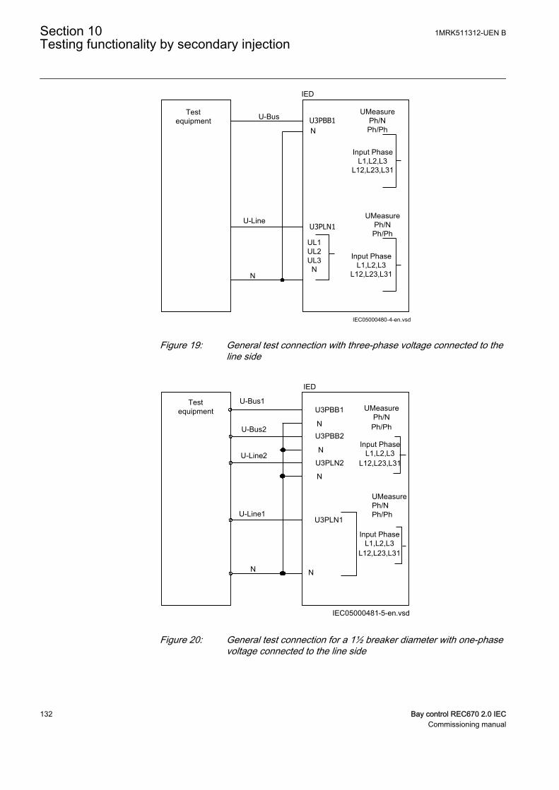
Testequipment
UMeasurePh/NPh/Ph
IEC05000480-4-en.vsd
U-Bus
U-Line
N
IED
U3PBB1N
UL1UL2UL3
N
Input PhaseL1,L2,L3
L12,L23,L31
UMeasurePh/NPh/Ph
Input PhaseL1,L2,L3
L12,L23,L31
U3PLN1
IEC05000480 V4 EN
Figure 19: General test connection with three-phase voltage connected to theline side
U-Bus1
U-Line1
N
Testequipment
IED
U3PBB1
N
IEC05000481-5-en.vsd
N
UMeasure Ph/NPh/Ph
U-Bus2
U-Line2
U3PBB2
U3PLN2
U3PLN1
N
N
Input PhaseL1,L2,L3
L12,L23,L31
UMeasurePh/NPh/Ph
Input PhaseL1,L2,L3
L12,L23,L31
IEC05000481 V5 EN
Figure 20: General test connection for a 1½ breaker diameter with one-phasevoltage connected to the line side
Section 10 1MRK511312-UEN BTesting functionality by secondary injection
132 Bay control REC670 2.0 IECCommissioning manual
10.9.1.1 Testing the synchronizing function
The voltage inputs used are:
UP3LN1 UL1, UL2 or UL3 line 1 voltage inputs on the IED
UP3BB1 Bus1 voltage input on the IED
Testing the frequency differenceThe frequency difference test should verify that operation is achieved when thefrequency difference between bus and line is less than set value of FreqDiffMaxandabove set value of FreqDiffMin. The test procedure below will depend on the settingsused. Input STARTSYN must be activated during the test.
FreqDiffMax = 50.2 Hz
FreqDiffMin = 50.01 Hz
tBreaker = 0.080 s
1. Apply voltages1.1. U-Line = 100% UBaseLine and f-Line = 50.0 Hz1.2. U-Bus = 100% UBaseBus and f-Bus = 50.15Hz
2. Check that a closing pulse is submitted at a closing angle equal to calculatedphase angle value from the formula below. Modern test sets will evaluate thisautomatically.Closing Angle = |( (fBus– fLine) * tBreaker * 360 degrees) |fBus= Bus frequencyfLine= Line frequencytBreaker = Set closing time of the breaker
3. Repeat with3.1. U-Bus = 100% UBaseBus and f-bus = 50.25 Hz, to verify that the function
does not operate when frequency difference is above limit.4. Verify that the closing command is not issued when the frequency difference is
less than the set value FreqDiffMin.
10.9.1.2 Testing the synchrocheck check
During the test of SESRSYN for a single bay arrangement, these voltage inputs areused:
U-Line UL1, UL2 or UL3 line 1 voltage input on the IED according to the connection in SMT
U-Bus Bus voltage input on the IED according to the connection in SMT
1MRK511312-UEN B Section 10Testing functionality by secondary injection
Bay control REC670 2.0 IEC 133Commissioning manual

Testing the voltage differenceSet the voltage difference to 0.15 p.u. on the local HMI, and the test should check thatoperation is achieved when the voltage difference UDiffSC is lower than 0.15 p.u.
The settings used in the test shall be final settings. The test shall be adapted to sitesetting values instead of values in the example below.
Test with no voltage difference between the inputs.
Test with a voltage difference higher than the set UDiffSC.
1. Apply voltages U-Line (for example) = 80% GblBaseSelLine and U-Bus = 80%GblBaseSelBusGblBaseSelBus with the same phase-angle and frequency.
2. Check that the AUTOSYOK and MANSYOK outputs are activated.3. The test can be repeated with different voltage values to verify that the function
operates within the set UDiffSC. Check with both U-Line and U-Busrespectively lower than the other.
4. Increase the U-Bus to 110% GblBaseSelBus, and the U-Line = 90%GblBaseSelLine and also the opposite condition.
5. Check that the two outputs for manual and auto synchronism are not activated.
Testing the phase angle differenceThe phase angle differences PhaseDiffM and PhaseDiffA respectively are set to theirfinal settings and the test should verify that operation is achieved when the phase angledifference is lower than this value both leading and lagging.
Test with no voltage difference.
1. Apply voltages U-Line (for example) = 100% GblBaseSelLine and U-Bus =100% GblBaseSelBus, with a phase difference equal to 0 degrees and afrequency difference lower than FreqDiffA and FreqDiffM.
2. Check that the AUTOSYOK and MANSYOK outputs are activated.The test can be repeated with other phase difference values to verify that thefunction operates for values lower than the set ones, PhaseDiffM andPhaseDiffA. By changing the phase angle on the voltage connected to U-Bus,between ± dφ degrees, the user can check that the two outputs are activated fora phase difference lower than the set value. It should not operate for other values.See figure 21.
Section 10 1MRK511312-UEN BTesting functionality by secondary injection
134 Bay control REC670 2.0 IECCommissioning manual
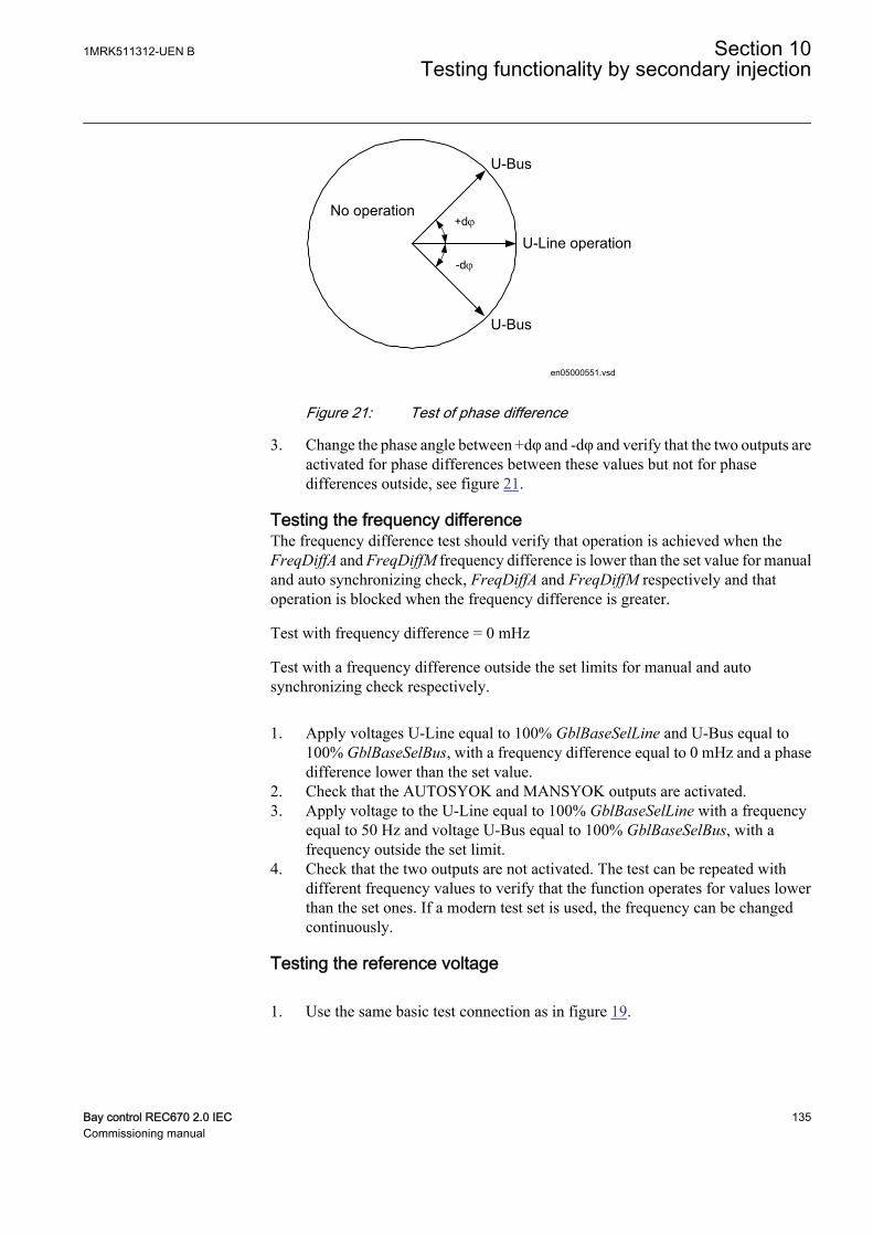
+dj
-dj
U-Bus
U-Line operation
U-Bus
No operation
en05000551.vsd
IEC05000551 V1 EN
Figure 21: Test of phase difference
3. Change the phase angle between +dφ and -dφ and verify that the two outputs areactivated for phase differences between these values but not for phasedifferences outside, see figure 21.
Testing the frequency differenceThe frequency difference test should verify that operation is achieved when theFreqDiffA and FreqDiffM frequency difference is lower than the set value for manualand auto synchronizing check, FreqDiffA and FreqDiffM respectively and thatoperation is blocked when the frequency difference is greater.
Test with frequency difference = 0 mHz
Test with a frequency difference outside the set limits for manual and autosynchronizing check respectively.
1. Apply voltages U-Line equal to 100% GblBaseSelLine and U-Bus equal to100% GblBaseSelBus, with a frequency difference equal to 0 mHz and a phasedifference lower than the set value.
2. Check that the AUTOSYOK and MANSYOK outputs are activated.3. Apply voltage to the U-Line equal to 100% GblBaseSelLine with a frequency
equal to 50 Hz and voltage U-Bus equal to 100% GblBaseSelBus, with afrequency outside the set limit.
4. Check that the two outputs are not activated. The test can be repeated withdifferent frequency values to verify that the function operates for values lowerthan the set ones. If a modern test set is used, the frequency can be changedcontinuously.
Testing the reference voltage
1. Use the same basic test connection as in figure 19.
1MRK511312-UEN B Section 10Testing functionality by secondary injection
Bay control REC670 2.0 IEC 135Commissioning manual
The voltage difference between the voltage connected to U-Bus and U-Lineshould be 0%, so that the AUTOSYOK and MANSYOK outputs are activatedfirst.
2. Change the U-Line voltage connection to U-Line2 without changing the settingon the local HMI. Check that the two outputs are not activated.
10.9.1.3 Testing the energizing check
During the test of the energizing check function for a single bay arrangement, thesevoltage inputs are used:
U-Line UL1, UL2 or UL3 line1 voltage inputs on the IED
U-Bus Bus voltage input on the IED
GeneralWhen testing the energizing check function for the applicable bus, arrangement shallbe done for the energizing check functions. The voltage is selected by activation ofdifferent inputs in the voltage selection logic.
Live voltage level is fixed to 80% UBase and dead voltage level to fixed 40% UBase.
The test shall be performed according to the settings for the station. Test thealternatives below that are applicable.
Testing the dead line live bus (DLLB)The test should verify that the energizing check function operates for a low voltage onthe U-Line and for a high voltage on the U-Bus. This corresponds to the energizing ofa dead line to a live bus.
1. Apply a single-phase voltage 100% GblBaseSelBus to the U-Bus, and a single-phase voltage 30% GblBaseSelLine to the U-Line.
2. Check that the AUTOENOK and MANENOK outputs are activated after settAutoEnerg respectively tManEnerg.
3. Increase the U-Line to 60% GblBaseSelLine and U-Bus to be equal to 100%GblBaseSelBus. The outputs should not be activated.
4. The test can be repeated with different values on the U-Bus and the U-Line.
Testing the dead bus live line (DBLL)The test should verify that the energizing check function operates for a low voltage onthe U-Bus and for a high voltage on the U-Line. This corresponds to an energizing ofa dead bus to a live line.
Section 10 1MRK511312-UEN BTesting functionality by secondary injection
136 Bay control REC670 2.0 IECCommissioning manual
1. Verify the settings AutoEnerg or ManEnerg to be DBLL.2. Apply a single-phase voltage of 30% GblBaseSelBus to the U-Bus and a single-
phase voltage of 100% GblBaseSelLine to the U-Line.3. Check that the AUTOENOK and MANENOK outputs are activated after set
tAutoEnerg respectively tManEnerg.4. Decrease the U-Line to 60% GblBaseSelLine and keep the U-Bus equal to 30%
GblBaseSelBus. The outputs should not be activated.5. The test can be repeated with different values on the U-Bus and the U-Line.
Testing both directions (DLLB or DBLL)
1. Verify the local HMI settings AutoEnerg or ManEnerg to be Both.2. Apply a single-phase voltage of 30% GblBaseSelLine to the U-Line and a single-
phase voltage of 100% GblBaseSelBus to the U-Bus.3. Check that the AUTOENOK and MANENOK outputs are activated after set
tAutoEnerg respectively tManEnerg.4. Change the connection so that the U-Line is equal to100% GblBaseSelLine and
the U-Bus is equal to 30% GblBaseSelBus. The outputs should still be activated.5. The test can be repeated with different values on the U-Bus and the U-Line.
Testing the dead bus dead line (DBDL)The test should verify that the energizing check function operates for a low voltage onboth the U-Bus and the U-Line, that is, closing of the breaker in a non-energizedsystem. Test is valid only when this function is used.
1. Verify the local HMI setting AutoEnerg to be Off and ManEnerg to be DBLL.2. Set the parameter ManEnergDBDL to On.3. Apply a single-phase voltage of 30% GblBaseSelBus to the U-Bus and a single-
phase voltage of 30% GblBaseSelLine to the U-Line.4. Check that the MANENOK output is activated after set tManEnerg.5. Increase the U-Bus to 80% GblBaseSelBus and keep the U-Line equal to 30%
GblBaseSelLine. The outputs should not be activated.6. Repeat the test with ManEnerg set to DLLB with different values on the U-Bus
and the U-Line voltage.
10.9.1.4 Testing the voltage selection
Testing the voltage selection for single CB arrangementsThis test should verify that the correct voltage is selected for the measurement in theSESRSYN function used in a double-bus arrangement. Apply a single-phase voltageof 100% GblBaseSelLine to the U-Line and a single-phase voltage of 100%GblBaseSelBus to the U-Bus.
If the UB1/2OK inputs for the fuse failure are used, they must be activated, duringtests below. Also verify that deactivation prevents operation and gives an alarm.
1MRK511312-UEN B Section 10Testing functionality by secondary injection
Bay control REC670 2.0 IEC 137Commissioning manual
1. Connect the signals above to binary inputs and binary outputs.2. Connect the voltage inputs to the analog inputs used for each bus or line
depending of the type of busbar arrangement and verify that correct outputsignals are generated.
Testing the voltage selection for double breakerThis test should verify that correct voltage is selected for the measurement in theSESRSYN function used for a diameter in a One-and-a-half breaker arrangement.Apply a single-phase voltage of 100% GblBaseSelLine to the U-Line and a single-phase voltage of 100% GblBaseSelBus to the U-Bus. Verify that correct output signalsare generated.
1. Connect the analog signals to the voltage inputs, in pair of two for U1 and U2.(Inputs U3PBB1, U3PBB2, U3PLN1, U3PLN2)
2. Activate the binary signals according to the used alternative. Verify themeasuring voltage on the synchronizing check function SESRSYN. Normally itcan be good to verify synchronizing check with the same voltages and phaseangles on both voltages. The voltages should be verified to be available whenselected and not available when another input is activated so connect only onevoltage transformer reference at each time.
3. Record the voltage selection tests in a matrix table showing read values andAUTOSYOK/MANSYOK signals to document the test performed.
Testing the voltage selection for 1 1/2 CB arrangementsAt test of the SESRSYN function for a 1½ CB diameter the following alternativevoltage inputs can be used for the three SESRSYN (SESRSYN 1, SESRSYN 2,SESRSYN 3) functions. These three SESRSYN functions can either be in one, two orthree different IEDs. Table 13 describes the scenario when SESRSYN 1, SESRSYN2 and SESRSYN 3 all are in the same IED. If SESRSYN 3 is in another IED, WA1 willbe considered as WA2 and LINE2 as LINE1. The voltage is selected by activation ofdifferent inputs in the voltage selection logic as shown in table 13 and figure 22.
Table 13: Voltage selection logic
SESRSYN CBConfigsetting
Section tobesynchronized
ActivatedB1QCLDinput onIED from
ActivatedB2QCLDinput onIED from
ActivatedLN1QCLDinput onIED from
ActivatedLN2QCLDinput onIED from
IndicationfromSESRSYNon IED
SESRSYN 1(Operates onWA1_QA1)
1 ½ busCB
WA1 –LINE1
LINE1_QB9
B1SEL,LN1SEL
WA1 –LINE2
TIE_QA1 LINE2_QB9
B1SEL,LN2SEL
WA1 –WA2
TIE_QA1 WA2_QA1
B1SEL,B2SEL
Table continues on next page
Section 10 1MRK511312-UEN BTesting functionality by secondary injection
138 Bay control REC670 2.0 IECCommissioning manual
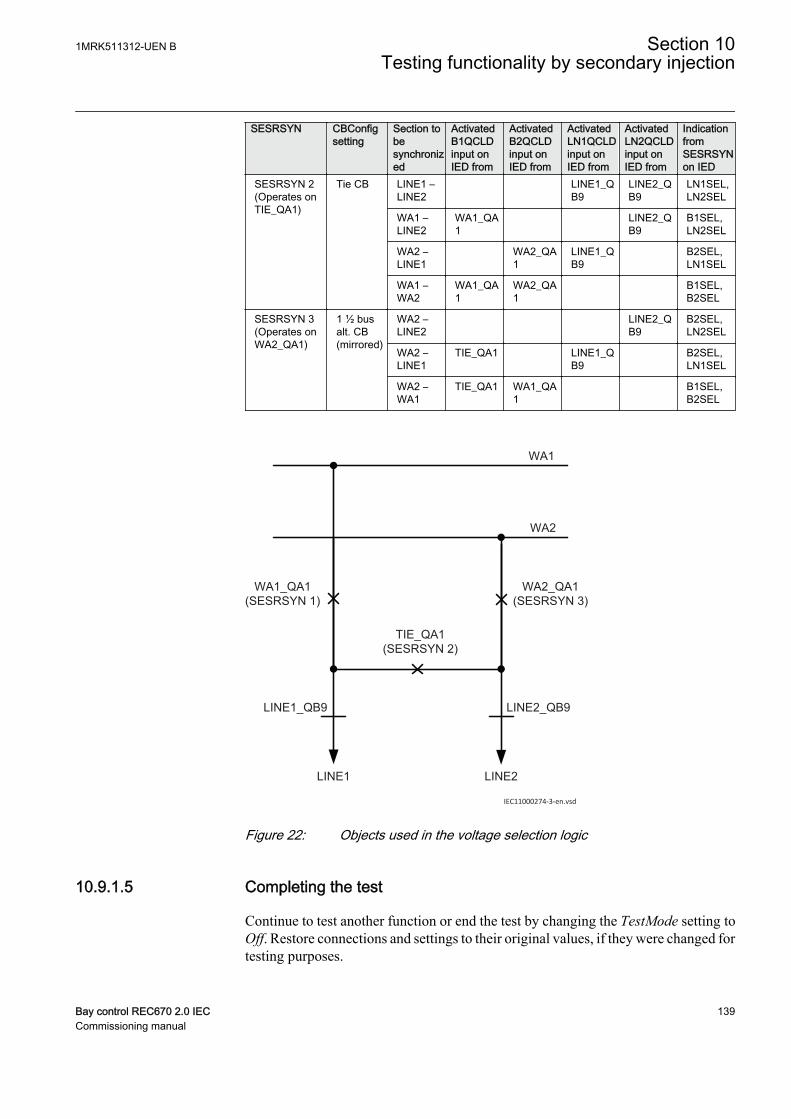
SESRSYN CBConfigsetting
Section tobesynchronized
ActivatedB1QCLDinput onIED from
ActivatedB2QCLDinput onIED from
ActivatedLN1QCLDinput onIED from
ActivatedLN2QCLDinput onIED from
IndicationfromSESRSYNon IED
SESRSYN 2(Operates onTIE_QA1)
Tie CB LINE1 –LINE2
LINE1_QB9
LINE2_QB9
LN1SEL,LN2SEL
WA1 –LINE2
WA1_QA1
LINE2_QB9
B1SEL,LN2SEL
WA2 –LINE1
WA2_QA1
LINE1_QB9
B2SEL,LN1SEL
WA1 –WA2
WA1_QA1
WA2_QA1
B1SEL,B2SEL
SESRSYN 3(Operates onWA2_QA1)
1 ½ busalt. CB(mirrored)
WA2 –LINE2
LINE2_QB9
B2SEL,LN2SEL
WA2 –LINE1
TIE_QA1 LINE1_QB9
B2SEL,LN1SEL
WA2 –WA1
TIE_QA1 WA1_QA1
B1SEL,B2SEL
WA1
WA2
WA1_QA1(SESRSYN 1)
WA2_QA1(SESRSYN 3)
TIE_QA1(SESRSYN 2)
LINE1 LINE2
LINE1_QB9 LINE2_QB9
IEC11000274-3-en.vsdIEC11000274 V3 EN
Figure 22: Objects used in the voltage selection logic
10.9.1.5 Completing the test
Continue to test another function or end the test by changing the TestMode setting toOff. Restore connections and settings to their original values, if they were changed fortesting purposes.
1MRK511312-UEN B Section 10Testing functionality by secondary injection
Bay control REC670 2.0 IEC 139Commissioning manual
10.9.2 Autorecloser for 1/2/3-phase operation SMBRREC
Verification of the Autorecloser for 1/2/3-phase operation function SMBRREC forsingle-phase, two-phase or three-phase reclosing attempts can be considered toconsist of two parts.
• One part to verify the internal logic and timing of the function• One part to verify its interaction with the protection system
This section deals with verification of SMBRREC itself. However, it is practical tostart SMBRREC by activating a protection function, for example, by secondaryinjection tests.
Prepare the IED for verification of settings outlined in section "Requirements" andsection "Preparing for test" in this chapter.
The purpose of verification before commissioning is to check that entered selections,setting parameters and configuration render the intended result. The function isflexible with many options and facilities. At commissioning only the selections andsettings intended for use are verified. If one chooses to reduce some time settings inorder to speed up verification, be careful to set the parameters at intended operationalvalues at the end of the verification procedure. One such parameter is the tReclaimtime that must be timed out before a new test sequence can be performed.
The verification test is performed together with protection and trip functions.Figure 23 illustrates a suggested testing arrangement, where the circuit-breaker (CB)is simulated by an external bi-stable relay (BR), for example a relay type RXMVB2or RXMD or Breaker Simulator of ABB. The following manual switches are used:
• Switch or push-button to close (SC)• Switch or push-button to trip (ST)• Switch for CB ready condition (SRY)
If no bi-stable relay or breaker simulator is available, replace it with two self-resetauxiliary relays and use a self-holding connection.
Use a secondary injection IED test set to operate the protection function. The test setshall be switched off when a trip signal is given or when the BR comes to open positionto simulate real conditions.
The CB simulation can be made more elaborate, including simulation of the operatinggear condition, CBREADY of either the type ready for a Close-Open (CO) cycle, orthe type ready for an Open-Close -Open (OCO) cycle.
The CB condition CBREADY of a type, CO, shall be high (true) until a closingoperation is performed. It then goes low (false) for a recharging time of about 5 - 10s.After that it is high again.
A CB condition CBREADY of a type, OCO shall be high (true) before and duringtripping (Start reclosing). During tripping it goes low for a recharging time, for
Section 10 1MRK511312-UEN BTesting functionality by secondary injection
140 Bay control REC670 2.0 IECCommissioning manual
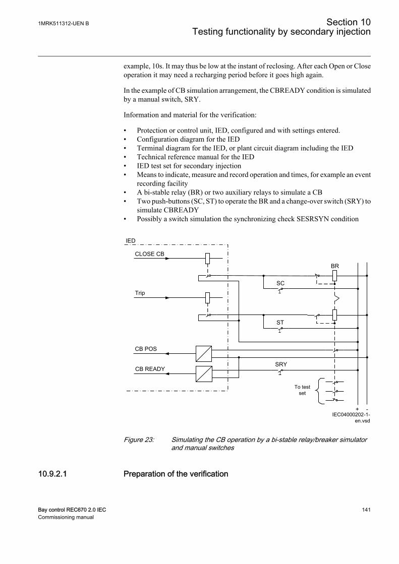
example, 10s. It may thus be low at the instant of reclosing. After each Open or Closeoperation it may need a recharging period before it goes high again.
In the example of CB simulation arrangement, the CBREADY condition is simulatedby a manual switch, SRY.
Information and material for the verification:
• Protection or control unit, IED, configured and with settings entered.• Configuration diagram for the IED• Terminal diagram for the IED, or plant circuit diagram including the IED• Technical reference manual for the IED• IED test set for secondary injection• Means to indicate, measure and record operation and times, for example an event
recording facility• A bi-stable relay (BR) or two auxiliary relays to simulate a CB• Two push-buttons (SC, ST) to operate the BR and a change-over switch (SRY) to
simulate CBREADY• Possibly a switch simulation the synchronizing check SESRSYN condition
IED
CLOSE CB
Trip
CB POS
CB READY
BR
SC
ST
SRY
To test set
+ -IEC04000202-1-
en.vsdIEC04000202 V2 EN
Figure 23: Simulating the CB operation by a bi-stable relay/breaker simulatorand manual switches
10.9.2.1 Preparation of the verification
1MRK511312-UEN B Section 10Testing functionality by secondary injection
Bay control REC670 2.0 IEC 141Commissioning manual
1. Check the function settings on the local HMI under Main menu/Settings/Setting group N/Control/Autorecloser79,5(0–>1)/SMBRREC:xIf any timer settings are reduced to speed up or facilitate the testing, they shall beset to normal after testing. A temporary label on the IED can be a reminder torestore normal settings after which a verification test should be performed.
2. Decide if a synchronizing check function SESRSYN shall be included in thetest.If SESRSYN as an internal function or external device is not operated by theinjection, input signal SYNC must be connected as a permanent high signal orcontrolled by a switch.
3. Read and make notes of the reclosing operation counters on the local HMI underMain menu/Test/Function status/Control/AutoRecloser79,5(0–>1)/SMBRREC:xPossibly reset the counters to Zero. Counters are reset in the reset menu.
4. Make arrangements for the simulation of the CB, for example as in figure 23.5. Make arrangements for indication, recording and time measurements.
The signals for CBPOS, START, CLOSECB, READY and other relevantsignals should preferably be arranged for event recording with time tagging. Ifthat is not possible, other means of time measurement and recording should bearranged.
10.9.2.2 Switching the autorecloser for 1/2/3-phase operation function to Onand Off
1. Set the Operation setting to Off and check the state.2. Set the Operation setting to On and check the state, including SETON and
READY.The CB should be closed and ready.
3. If external control inputs OFF/ON are used, check that they work. SetExternalCtrl = On and use the control inputs to switch On and Off, and check thestate of the function.
10.9.2.3 Verifying the autorecloser function SMBRREC
Select the test cases to be run according to what is applicable to the particularapplication. It can be, for example,
• three-phase single-shot reclosing• two-shot reclosing• single-phase and three-phase single-shot reclosing
Below, a case with single-phase and three-phase single-shot reclosing is described.
Section 10 1MRK511312-UEN BTesting functionality by secondary injection
142 Bay control REC670 2.0 IECCommissioning manual
1. Set Operation = On.2. If the synchronizing check SESRSYN is not to be operated, ensure that the signal
SYNC input is activated. If SESRSYN is to be included, ensure that it is suppliedwith the appropriate AC quantities.
3. Simulate CB closed position by closing switch SC to make the BR relay start.4. Simulate CBREADY by closing the switch SRY, and leave it closed.5. Inject AC quantities to give a trip, for example, one-phase trip, to the BR and to
the START input.Observe and preferably record the operation. The BR relay shall trip and reclose(start). After reclosing, the SRY switch can be opened for about 5s and thenclosed again.The autoreclosing open time and the sequence should be checked, for examplein the event recording. Check also the operation indications (disturbance report)and the operation counters on the local HMI under Main menu/Test/Functionstatus/Control/AutoRecloser(RREC,79)/SMBRREC:xShould the operation not be as expected, this should be investigated. It could becaused by an inappropriate setting or missing condition such as CBREADY.
6. Repeat the sequence by simulating a permanent fault.Shortly after the reclosing shot, a new fault is applied. If a single-shot reclosingprogram is selected, there shall be one reclosing operation and then blocking ofSMBRREC for the set Reclaim time.Before a new reclosing sequence can be run, the CBREADY and CBPOS (CBclosed) must be set manually.
7. Repeat the sequence by simulating a three-phase transient and permanent faults,and other applicable cases, such as signal to STARTHS and high-speedreclosing.If just single-phase reclosing is selected, FirstShot = 1ph, a check can be run tomake sure that a three-phase trip does not result in any reclosing. Other similarcases can be checked as required.
10.9.2.4 Checking the reclosing conditions
When checking the influence of a releasing condition it is suggested to first run asequence with the condition fulfilled. When the condition signal is removed, and anew sequence is run, it indicates that the result was due to the changed condition. Incase of a blocking signal the procedure should be similar. Start without the blockingor inhibit signal, and then run a sequence with the blocking or inhibit signal added.
Checking the influence of the INHIBIT signal
1. Check that the autorecloser function SMBRREC is operative, for example, bymaking a reclosing shot without the INHIBIT signal.
2. Apply a fault and thereby a START signal. At the same time, or during the opentime, apply a signal to the input INHIBIT.
3. Check that the reclosing sequence is interrupted and no reclosing takes place.
Check closing onto a fault
1MRK511312-UEN B Section 10Testing functionality by secondary injection
Bay control REC670 2.0 IEC 143Commissioning manual
1. Check that the autorecloser function SMBRREC is operative, for example bymaking a reclosing shot.Keep the CBREADY signal high.
2. Set the breaker simulating relay BR in Open position.3. Close the BR relay and apply immediately a fault and thereby a START signal.4. Check that no reclosing takes place.
Checking the influence of CB not ready for reclosing
1. Check that the autorecloser function SMBRREC is operative, for example bymaking a reclosing shot.Keep the CB simulator BR closed. Remove the CBREADY signal by openingSRY.
2. Apply a fault and thereby a START signal.3. Check that no reclosing takes place.
Checking the influence of synchronizing check (at three-phasereclosing)
1. Check that the autorecloser function SMBRREC is operative, for example, bymaking a three-phase reclosing shot with the SESRSYN synchronizing checkcondition.Set the SESRSYN function to Off to eliminate the signal connected to inputsignal SYNC.
2. Apply a fault causing three-phase trip and thereby a START and a TR3P signal.3. Wait for the tSync time-out limit.
Check that no reclosing is made.
Checking the response when autoreclosing is OffProcedure
1. Check that the autorecloser function SMBRREC is operative, for example bymaking a reclosing shot.Set the autoreclosing operation to Off, for example by external control.The output READY shall be low, and PREP3P shall be high.
2. Apply a single phase fault and thereby a START signal.3. Check that a definitive three phase trip and no reclosing takes place.
Testing autoreclosing in a multi-breaker arrangementThe usual arrangement is to have an autorecloser function SMBRREC per circuit-breaker. They can be in different CB related IEDs or in a common IED.
• A master SMBRREC function is set with Priority = High.• A slave SMBRREC function is set with Priority = Low.
Section 10 1MRK511312-UEN BTesting functionality by secondary injection
144 Bay control REC670 2.0 IECCommissioning manual
See the application manual for an illustration of typicalinterconnections.
The two functions can be checked individually by carefully applying START, WAIT,and INHIBIT signals.
It is also possible to verify the two functions together by using CB simulatingequipment for two CB circuits. There should be interconnections from the master tothe slave function, WFMASTER - WAIT, and UNSUCCL - INHIBIT, as shown in theillustration referred to above.
Restoring equipmentAfter the tests, restore the equipment to normal or desired state. Check the followingitems in particular:
1. Check the operation counters.Reset the counters to zero, if that is the user's preference. The counter resetfunction is found on the local HMI under Main menu/Reset/Reset counters/AutoRecloser79,5(0–>1)/SMBRREC:x
2. Restore settings that may have been modified for the tests back to normal.3. Disconnect the test switch, CB simulating arrangement and test circuits.
Reconnect any links or connection terminals, which may have been opened forthe tests.
4. Reset indications, alarms and disturbance recordings.Clearing of the disturbance report can be done via the Disturbance Handling inPCM600 or the local HMI.
10.9.2.5 Completing the test
Continue to test another function or end the test by changing the TestMode setting toOff. Restore connections and settings to their original values, if they were changed fortesting purposes.
10.9.3 Apparatus control APC
The apparatus control function consists of four types of function blocks, which areconnected in a delivery-specific way between bays and to the station level. For thatreason, test the total function in a system, that is, either in a complete delivery systemas an acceptance test (FAT/SAT) or as parts of that system.
If a block/unblock command is sent from remote to function, while theIED is shut down, this command will not be recognized after the startup, thus the command that was sent prior to the shut down is used. Insuch cases, where there is a mismatch, the user is advised to make acomplete cycle of block/unblock operations to align the statuses.
1MRK511312-UEN B Section 10Testing functionality by secondary injection
Bay control REC670 2.0 IEC 145Commissioning manual

10.9.4 Voltage control (VCTR) TR1ATCC, TR8ATCC, TCMYLTC,TCLYLTC
Prepare the IED for verification of settings outlined in section "Requirements" andsection "Preparing for test" in this chapter.
The automatic voltage control for tap changer, single control TR1ATCC is based ona transformer configuration that consists of one tap changer on a single two-windingpower transformer.
The automatic voltage control for tap changer, parallel control TR8ATCC, if installed,may be set to operate in Master Follower (MF) mode, or Minimise Circulating Current(MCC) mode. The commissioning tests for each parallel control mode are addressedseparately in the following procedure.
Secondary injection of load current (IL) and secondary bus voltage (UB) equivalentquantities are required during installation and commissioning tests. The test consistsmainly of:
1. Increasing or decreasing the injected voltage or current at the analogue inputs ofthe IED.
2. Checking that the corresponding commands (Lower or Raise) are issued by thevoltage control function.
Setting confirmation is an important step for voltage control in the installation andcommissioning phase to ensure consistency of power systems base quantities, alarm/blocking conditions and parallel control settings for each transformer controlfunction.
Before starting any test, verify the following settings in PCM600 or the local HMI forTR1ATCC, TR8ATCC and TCMYLTC and TCLYLTC.
• Confirm power system base quantities I1Base, I2Base, UBase.
Main menu/Settings/Setting Group N/Control/TransformerVoltageControl(ATCC,90)/TR1ATCC:x/TR8ATCC:x/General
and
Main menu/Settings/Setting Group N/Control/TransformerVoltageControl(ATCC,90)/TR1ATCC:x
.
• Confirm that the setting for short circuit impedance Xr2 for TR1ATCC orTR8ATCC is in accordance with transformer data:• Short circuit impedance, available on the local HMI under Main menu/
Settings/General settings/Control/
Section 10 1MRK511312-UEN BTesting functionality by secondary injection
146 Bay control REC670 2.0 IECCommissioning manual
TransformerVoltageControl(ATCC,90)/TR1ATCC:x/TR8ATCC:x/Xr2.
• Confirm that the setting for TCMYLTC or TCLYLTC is in accordance withtransformer data:• Tap change timeout duration - effectively the maximum transformer tap
change time, tTCTimeout, available on the local HMI under Main menu/Settings/Setting Group N/Control/TransformerTapControl(YLTC,84)/TCMYLTC:x/TCLYLTC:x/tTCTimeout.
• Load tap changer pulse duration - required length of pulse from IED to loadtap changer, tPulseDur, available on the local HMI under Main menu/Settings/Setting Group N/Control/TransformerTapControl(YLTC,84)/TCMYLTC:x/TCLYLTC:x/tPulseDur.
• Transformer tap range, LowVoltTap and HighVoltTap, available on thelocal HMI under Main menu/Settings/General Settings/Control/TransformerTapControl(YLTC,84)/TCMYLTC:x/TCLYLTC:x/HighVoltTap and .
• Load tap changer code type - method for digital feedback of tap position,CodeType, available on the local HMI under Main menu/Settings/General settings/Control/TransformerTapControl(YLTC,84)/TCMYLTC:x/TCLYLTC:x/CodeType.
During the installation and commissioning, the behavior of thevoltage control functions for different tests may be governed by aparameter group, available on the local HMI under Main menu/Settings/General settings/Control/TransformerVoltageControl(ATCC,90)/TR1ATCC:x/TR8ATCC:x. These parameter settings can cause a Total Block,Automatic Block or Alarm for a variety of system conditionsincluding over and under voltage, over current and tap changer failure.It is important to review these settings and confirm the intendedresponse of the voltage control function for different secondaryinjection tests.
TerminologyThe busbar voltage UB is a shorter notation for the measured voltages Ua, Ub, Uc orUij, where Uij is the phase-phase voltage, Uij = Ui -Uj, or Ui, where Ui is one single-phase-to-earth voltage.
IL is a shorter notation for the measured load current; it is to be used instead of thethree-phase quantities Ia, Ib, Ic or the two-phase quantities Ii and Ij, or single-phasecurrent Ii.
Also note that for simplicity, the Parameter Setting menu structuresincluded in the following procedure are referred to universally asVCP1, for example, Main menu/Settings/Setting Group N/
1MRK511312-UEN B Section 10Testing functionality by secondary injection
Bay control REC670 2.0 IEC 147Commissioning manual
Control/TransformerVoltageControl(ATCC,90)/TR1ATCC:x/TR8ATCC:x/Time/t1 and t2l.
For cases where single-mode voltage control is implemented, the Parameter Settingmenu structure includes TR1ATCC:1 instead of the parallel designator TR8ATCC:1.
10.9.4.1 Secondary test
The voltage control function performs basic voltage regulation by comparing acalculated load voltage (UL) against a voltage range defined by setting UDeadband(with upper and lower limits U2 and U1 respectively). The calculated load voltage ULrepresents the secondary transformer bus voltage UB adjusted for Load dropcompensation (LDC) where enabled in settings.
Note that when LDC is disabled, UB equals UL.
When the load voltage UL stays within the interval between U1 and U2, no action willbe taken.
If UL < U1 or UL > U2, a command timer will start, which is constant time or inversetime defined by setting t1 and t1Use. The command timer will operate while themeasured voltage stays outside the inner deadband (defined by settingUDeadbandInner).
If UL remains outside of the voltage range defined by UDeadband and the commandtimer expires, the voltage control will execute a raise or lower command to thetransformer tap changer. This command sequence will be repeated until UL is broughtback within the inner deadband range.
10.9.4.2 Check the activation of the voltage control operation
1. Confirm Transformer Tap Control = On and Transformer Voltage Control = On• Direct tap change control
Main menu/Settings/Setting Group N/Control/TransformerTapChanger(YLTC,84)/TCMYLTC:x/TCLYLTC:x/Operation• Automatic transformer voltage control
Main menu/Settings/Setting Group N/Control/TransformerVoltageControl(ATCC,90)/TR1ATCC:x/TR8ATCC:x/General/Operation• Enable Tap Command
Section 10 1MRK511312-UEN BTesting functionality by secondary injection
148 Bay control REC670 2.0 IECCommissioning manual
Main menu/Settings/General settings/Control/TransformerTapChanger(YLTC,84)/TCMYLTC:x/TCLYLTC:x/EnabTapCmdWhile the test set is connected to the IED but no voltage is applied, the voltagecontrol functions will detect an undervoltage condition that may result in analarm or blocking of the voltage-control operation. These conditions will beshown on the local HMI.
2. Apply the corresponding voltageConfirm the analog measuring mode prior to undertaking secondary injection(positive sequence, phase-to-phase, or phase-to-earth). This measuring mode isdefined in the local HMI under Main menu/Settings/Setting Group N/Control/TransformerVoltageControl(ATCC,90)/TR1ATCC:x/TR8ATCC:x/General/MeasModeThe application of nominal voltage USet according to set MeasMode to the IEDsshould cause the alarm or blocking condition for undervoltage to reset.
10.9.4.3 Check the normal voltage regulation function
1. Review the settings for UDeadband (based on percentage of nominal busvoltage) and calculate the upper (U2) and lower (U1) voltage regulation limitsfor which a tap change command will be issued.
2. Review the expected time for first (t1) and subsequent (t2) tap changecommands from the voltage control function on the local HMI under Mainmenu/Settings/Setting Group N/Control/TransformerVoltageControl(ATCC,90)/TR1ATCC:x/TR8ATCC:x/Time/t1 and t2l
3. Lower the voltage 1% below U1 and wait for the issue of a Raise command fromthe voltage control after the expiry of a constant or inverse time delay set by t1.Detection of this command will involve locating the allocated binary output fora raise pulse command in the Signal Matrix in PCM600 and monitoring apositive from this output.
4. After the issue of the raise command, return the applied voltage to USet (nominalvalue).
5. Raise the voltage 1% above the upper deadband limit U2 and wait for the issueof a lower command from the voltage control after the expiry of a constant orinverse time delay set by t1. Detection of this command will involve locating theallocated binary output for a low pulse command in the Signal Matrix inPCM600 and monitoring a positive from this output.
6. Return the applied voltage to USet.
10.9.4.4 Check the undervoltage block function
1. Confirm the setting for Ublock, nominally at 80% of rated voltage.2. Confirm the voltage control function response to an applied voltage below
Ublock, by reviewing the setting in the local HMI under Main menu/Settings/
1MRK511312-UEN B Section 10Testing functionality by secondary injection
Bay control REC670 2.0 IEC 149Commissioning manual
General settings/Control/TransformerVoltageControl(ATCC,90)/TR1ATCC:x/TR8ATCC:x/UVBk that may cause an alarm, total or automaticblock of the voltage control function to be displayed on the local HMI.
3. Apply a voltage slightly below Ublock and confirm the response of the voltagecontrol function.
10.9.4.5 Check the upper and lower busbar voltage limit
1. Confirm the settings for Umin and Umax in the local HMI under Main menu/Settings/Setting group N/Control/TransformerVoltageControl(ATCC,90)/TR1ATCC:x/TR8ATCC:x/Voltage/Umax or Umin and Main menu/Settings/IED Settings/Control/TR8ATCC (90)/TR8ATCC:n/Voltage/Umax
2. Confirm the voltage control function response to an applied voltage below Uminand above Umax, by reviewing the settings in the local HMI under Main menu/Settings/General settings/Control/TransformerVoltageControl(ATCC,90)/TR1ATCC:x/TR8ATCC:x/UVPartBk and Main menu/GeneralSettings/Control/TransformerVoltageControl/TR1ATCC:x/TR8ATCC:x/OVPartBk. These conditions may cause an alarm or total blockof the voltage control function to be displayed on the local HMI.
3. Decrease the injected voltage slightly below the Umin value and check for thecorresponding blocking or alarm condition on the local HMI. For an alarmcondition, the voltage regulation function is not blocked and a raise commandshould be issued from the IED.
4. Increase the applied voltage slightly above the Umax value and check for thecorresponding blocking or alarm condition on the local HMI. For an alarmcondition, the voltage regulation function is not blocked and a lower commandshould be issued from the IED.
10.9.4.6 Check the overcurrent block function
1. Confirm the setting for Iblock in the local HMI under Main menu/Settings/Setting group N/Control/TransformerVoltageControl(ATCC,91)/TR1ATCC:x/TR8ATCC:x/TCCtrl/Iblock
2. Confirm the voltage control function response to an applied current aboveIblock, by reviewing the settings in the local HMI under Main menu/Settings/General settings/Control/TransformerVoltageControl(ATCC,91)/TR1ATCC:x/TR8ATCC:x/OVPartBk. This condition may cause an alarm ortotal block of the voltage control function to be displayed on the local HMI.
3. Inject a current higher than the Iblock setting and confirm the alarm or blockingcondition is present on the local HMI. If an automatic or total blocking conditionoccurs, change the applied secondary voltage and confirm that no tap changecommands are issued from the associated binary outputs. This situation can alsobe confirmed through reviewing the disturbance and service reports on the localHMI.
Section 10 1MRK511312-UEN BTesting functionality by secondary injection
150 Bay control REC670 2.0 IECCommissioning manual
10.9.4.7 Single transformer
Load drop compensation
1. Confirm that OperationLDC is set to On.2. Confirm settings for Rline and Xline.3. Calculate the expected load voltage UL (displayed as a measured value on the
local HMI) based on secondary injection of transformer secondary voltage (UB =USet) and rated load current (IL = I1Base), in accordance with equation 36.
EQUATION2080 V3 EN (Equation 36)
where:
UL, IL = Re(IL) + jlm(IL) are complex phase quantities
When all secondary phase-to-earth voltages are available, use the positive-sequence components of voltage and current. By separation of real andimaginary parts:
, , , ,ul re ub re rline il re xline il im= - × + ×
EQUATION2082 V1 EN (Equation 37)
, , , ,ul im ub im xline il re rline il im= - × - ×
EQUATION2084 V1 EN (Equation 38)
where:
ub is the complex value of the busbar voltage
il is the complex value of the line current (secondary side)
rline is the value of the line resistance
xline is the value of the line reactance
For comparison with the set-point value, the modulus of UL are according toequation 39.
¦ UL¦ = (ul , re)2 + (ul , im)2
EQUATION2086 V2 EN (Equation 39)
4. Inject voltage for UB equal to setting USet.5. Inject current equal to rated current I2Base.6. Confirm on the local HMI that service values for bus voltage and load current are
equal to injected quantities.
1MRK511312-UEN B Section 10Testing functionality by secondary injection
Bay control REC670 2.0 IEC 151Commissioning manual

7. Confirm that the calculated value for load voltage, displayed on the local HMI,is equal to that derived through hand calculations.
8. When setting OperationLDC set to On, the voltage regulation algorithm uses thecalculated value for load voltage as the regulating quantity to compare againstUSet and the voltage deadband limits UDeadband and UDeadbandInner.
9. While injecting rated current I2Base into the IED, inject a quantity for UB thatis slightly higher then USet + |(Rline+jXLine) · IL|. This will ensure that theregulating voltage UL is higher than USet, and hence no tap change commandshould be issued from the IED.
10. Reduce the injected voltage for UB slightly below USet + |(Rline+jXLine) · IL|and confirm that the calculated value for load voltage is below USet and a tapchange command is issued from the IED.
10.9.4.8 Parallel voltage regulation
Master follower voltage regulation
1. For the transformers connected in the parallel group, confirm thatOperationPAR is set to MF.
2. For parallel operation, it is also recommended to confirm for parallel groupmembership, defined by setting TnRXOP in the local HMI under Main menu/Settings/Setting group N/Control/TransformerVoltageControl(ATCC,90)/TR8ATCC:x/ParCtrlThe general parallel arrangement of transformers are defined by settingTnRXOP to On or Off. The following rules are applicable on the settingsT1RXOP – T4RXOP.If IED T1 and T2 are connected,• T1RXOP shall be set to On in instance 2 of TR8ATCC,• T2RXOP shall be set to On in instance 3 of TR8ATCC,• T2RXOP and T3RXOP shall be set to On in instance 1 of TR8ATCC, and
so on.
The parameter corresponding to the own IED must not be set.T1RXOP should thus not be set in IED T1, T2RXOP not in IEDT2, and so on.
3. The lowest transformer number in the parallel group is by default set as theMaster – confirm that this is the case by reviewing the setting in the local HMI.
4. Review the settings for UDeadband (based on percentage of nominal busvoltage) and calculate the upper (U2) and lower (U1) voltage regulation limitsfor which a tap change command will be issued from the master transformer inthe group.
5. Review the expected time for first (t1) and subsequent (t2) tap changecommands from the master transformer in the local HMI under Main menu/
Section 10 1MRK511312-UEN BTesting functionality by secondary injection
152 Bay control REC670 2.0 IECCommissioning manual

Settings/Setting group N/Control/TransformerVoltageControl(ATCC,90)/TR1ATCC:x/TR8ATCC:x/Time/t1 and t2
6. Apply a voltage 1% below U1 and wait for the issue of a raise command from thevoltage control after the expiry of a constant or inverse time delay set by t1.Detection of this command will involve locating the allocated binary output fora raise command in the Signal Matrix in PCM600 and monitoring a positivefrom this output. Confirm the timing of this command correlates with the settingt1.
7. After the issue of the raise command, confirm that all follower transformers inthe group change tap in accordance with the command issued from the mastertransformer.
8. Inject a voltage UB for the master transformer that is 1% above the upperdeadband limit U2 and wait for the issue of a lower command from the voltagecontrol after the expiry of a constant or inverse time delay set by t2.
9. Confirm that all follower transformers in the group change tap in accordancewith this command.
Circulating current voltage regulationThis instruction for confirmation of circulating current voltage regulation assumestwo transformers in the parallel group. Setting confirmation through secondaryinjection requires calculation of circulating currents for each transformer based onimpedance values and respective compensating factors, and is therefore morecomplex for greater than two transformers.
1. Confirm that OperationPAR is set to CC for the transformers in the parallelgroup.
2. For parallel operation, it is also recommended that settings be confirmed forparallel group membership, governed by setting TnRXOP in the local HMIunder Main menu/Settings/Setting group N/Control/TransformerVoltageControl(ATCC,90)/TR8ATCC:x/ParCtrlThe general parallel arrangement of transformers are defined by settingTnRXOP to On or Off. The following rules are applicable on the settingsT1RXOP - T4RXOP.If IED T1 and T2 are connected,• T1RXOP shall be set to On in instance 2 of TR8ATCC, and• T2RXOP shall be set to On in instance 1 of TR8ATCC.
If T1 - T3 are available,• T1RXOP and T2RXOP shall be set to On in instance 3 of TR8ATCC,• T2RXOP and T3RXOP shall be set to On in instance 1 of TR8ATCC and
so on.
1MRK511312-UEN B Section 10Testing functionality by secondary injection
Bay control REC670 2.0 IEC 153Commissioning manual
The parameter corresponding to the own IED must not be set.T1RXOP should thus not be set in IED T1, T2RXOPnot in IEDT2 and so on.
3. Review the settings for UDeadband (based on percentage of nominal busvoltage) and calculate the upper (U2) and lower (U1) voltage regulation limitsfor which a tap change command will be issued from the master transformer inthe group.
4. Review the expected time for first (t1) and subsequent (t2) tap changecommands from the master transformer in the local HMI under Main menu/Settings/Setting group N/TransformerVoltageControl(ATCC,90)/TR1ATCC:x/TR8ATCC:x/Time/t1 and t2
5. Inject a voltage UB equal to USet for each transformer.6. Inject a load current for Transformer 1 that is equal to rated load current I2Base
and a load current for Transformer 2 that is equal to 95% of rated load currentI2Base. This will have the effect of producing a calculated circulating currentthat flows from HV to LV side for Transformer 1 and LV to HV side forTransformer 2.
7. Confirm that a circulating current is measured on the local HMI that is equal inmagnitude to 5% of I2Base, with polarity as discussed in step 6.
8. Confirm the settings for Ci (Compensation Factor) and Xi (Transformer ShortCircuit Impedance). Using these setting values and the measured quantity ofcirculating current from the local HMI (Icc_i), calculate the value for circulatingcurrent voltage adjustment Uci.
_Udi Ci Icc i Xi= × ×EQUATION2088 V1 EN (Equation 40)
The voltage regulation algorithm then increases (for transformer T2) ordecreases (for transformer T1) the measured voltage by Udi and compares Uiagainst the voltage deadband limits U1 and U2 for the purposes of voltageregulation.
EQUATION2090 V3 EN (Equation 41)
9. To cause a tap change, the calculated value for circulating current voltageadjustment must offset the injected quantity for bus voltage UB so that Ui isoutside the voltage deadband created by setting UDeadband. Expressed byequation 42 and equation 43.
Section 10 1MRK511312-UEN BTesting functionality by secondary injection
154 Bay control REC670 2.0 IECCommissioning manual
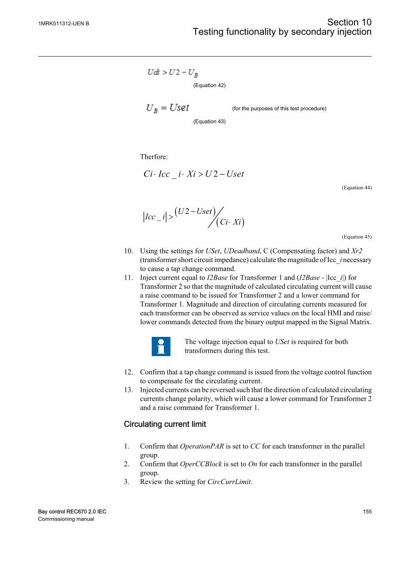
EQUATION2092 V2 EN (Equation 42)
EQUATION2094 V2 EN (Equation 43)
(for the purposes of this test procedure)
Therfore:
_ 2Ci Icc i Xi U Uset× × > -EQUATION2096 V1 EN (Equation 44)
( )( )
2_ U UsetIcc i Ci Xi-
>×
EQUATION2098 V1 EN (Equation 45)
10. Using the settings for USet, UDeadband, C (Compensating factor) and Xr2(transformer short circuit impedance) calculate the magnitude of Icc_i necessaryto cause a tap change command.
11. Inject current equal to I2Base for Transformer 1 and (I2Base - |Icc_i|) forTransformer 2 so that the magnitude of calculated circulating current will causea raise command to be issued for Transformer 2 and a lower command forTransformer 1. Magnitude and direction of circulating currents measured foreach transformer can be observed as service values on the local HMI and raise/lower commands detected from the binary output mapped in the Signal Matrix.
The voltage injection equal to USet is required for bothtransformers during this test.
12. Confirm that a tap change command is issued from the voltage control functionto compensate for the circulating current.
13. Injected currents can be reversed such that the direction of calculated circulatingcurrents change polarity, which will cause a lower command for Transformer 2and a raise command for Transformer 1.
Circulating current limit
1. Confirm that OperationPAR is set to CC for each transformer in the parallelgroup.
2. Confirm that OperCCBlock is set to On for each transformer in the parallelgroup.
3. Review the setting for CircCurrLimit.
1MRK511312-UEN B Section 10Testing functionality by secondary injection
Bay control REC670 2.0 IEC 155Commissioning manual
4. Review the setting for CircCurrBk to confirm whether a circulating current limitwill result in an Alarm state, Auto Block or Auto&Man Block of the automaticvoltage control for tap changer, for parallel control function TR8ATCC.
5. Inject a voltage UB equal to USet for each transformer.6. Inject a load current for Transformer 1 that is equal to rated load current I2Base
and a load current for Transformer 2 that is 1% less than (I2Base – (I2Base ·CircCurrLimit))
7. Confirm that the automatic voltage control for tap changer, for parallel controlfunction TR8ATCC responds in accordance with the setting for CircCurrBk.Alarm and blocking conditions can be confirmed through interrogation of theevent menu or the control menu on the local HMI.
VTmismatch during parallel operation
1. Confirm that OperationPAR is set to MF for each transformer in the parallelgroup.
2. Review the setting for VTmismatch and tVTmismatch.3. Inject a voltage UB equal to USet for Transformer 1 and a voltage less than (USet
– (VTmismatch · USet)) for Transformer 2.4. This condition should result in a VTmismatch which will mutually block the
operation of the automatic voltage control for tap changer, parallel controlfunction TR8ATCC for all transformers connected in the parallel group, whichcan be confirmed through interrogation of the local HMI.
5. Confirm that the automatic voltage control for tap changer, parallel controlfunction TR8ATCC responds in accordance with the setting for CircCurrBk.
10.9.4.9 Completing the test
Continue to test another function or end the test by changing the TestMode setting toOff. Restore connections and settings to their original values, if they were changed fortesting purposes.
10.9.5 Single command, 16 signals SINGLECMD
For the single command function block, it is necessary to configure the output signalto corresponding binary output of the IED. The operation of the single commandfunction (SINGLECMD) is then checked from the local HMI by applying thecommands with Mode = Off, Steady or Pulse, and by observing the logic statuses ofthe corresponding binary output. Command control functions included in theoperation of different built-in functions must be tested at the same time as theircorresponding functions.
10.9.6 Interlocking
Prepare the IED for verification of settings outlined in section "Requirements" andsection "Preparing for test" in this chapter.
Section 10 1MRK511312-UEN BTesting functionality by secondary injection
156 Bay control REC670 2.0 IECCommissioning manual
Values of the logical signals are available on the local HMI under Main menu/Tests/Function status/Control/Apparatus control/Interlocking. The Signal Monitoringin PCM600 shows the same signals that are available on the local HMI.
The interlocking function consists of a bay-level part and a station-level part. Theinterlocking is delivery specific and is realized by bay-to-bay communication over thestation bus. For that reason, test the function in a system, that is, either in a completedelivery system as an acceptance test (FAT/SAT) or as parts of that system.
10.10 Scheme communication
10.10.1 Scheme communication logic for distance or overcurrentprotection ZCPSCH
Prepare the IED for verification of settings outlined in section "Requirements" andsection "Preparing for test" in this chapter.
Check the scheme logic during the secondary injection test of the impedance orovercurrent protection functions.
Activation of the different zones verifies that the CS signal is issued from the intendedzones. The CS signal from the independent tripping zone must have a tSendMinminimum time.
Check the tripping function by activating the CR and CRG inputs with theoverreaching zone used to achieve the CACC signal.
It is sufficient to activate the zones with only one type of fault with the secondaryinjection.
10.10.1.1 Testing permissive underreaching
1. Activate the receive (CR) signal in the IED.2. Apply healthy normal load conditions to the IED for at least two seconds.3. Apply a fault condition within the permissive zone.4. Check that correct trip outputs, external signals, and indications are obtained for
the actual type of fault generated.5. Check that other zones operate according to their zone timers and that the send
(CS) signal is obtained only for the zone configured to generate the actual signal.6. Deactivate the receive (CR) signal in the IED.7. Check that the trip time complies with the zone timers and that correct trip
outputs, external signals, and indications are obtained for the actual type of faultgenerated.
1MRK511312-UEN B Section 10Testing functionality by secondary injection
Bay control REC670 2.0 IEC 157Commissioning manual
10.10.1.2 Testing permissive overreaching
1. Activate the receive (CR) signal in the IED.2. Apply healthy normal load conditions to the IED for at least two seconds.3. Apply a fault condition within the permissive zone.4. Check that correct trip outputs, external signals, and indication are obtained for
the actual type of fault generated.5. Check that the other zones operate according to their zone timer and that the send
(CS) signal is obtained only for the zones that are configured to give the actualsignal. Also the zone connected to CS underreach is giving CS in this mode.
6. Deactivate the IED receive (CR) signal.7. Apply healthy normal load conditions to the IED for at least two seconds.8. Apply a fault condition within the permissive zone.9. Check that trip time complies with the zone timers and that correct trip outputs,
external signals, and indications are obtained for the actual type of faultgenerated.
10.10.1.3 Testing blocking scheme
1. Deactivate the receive (CR) signal of the IED.2. Apply healthy normal load conditions to the IED for at least two seconds.3. Apply a fault condition within the forward directed zone used for scheme
communication tripping.4. Check that correct trip outputs and external signals are obtained for the type of
fault generated and that the operate time complies with the tCoord timer (plusrelay measuring time).
5. Check that the other zones operate according to their zone times and that a send(CS) signal is only obtained for the reverse zone.
6. Activate the IED receive (CR) signal.7. Apply a fault condition in the forward directed zone used for scheme
communication tripping.8. Check that the no trip from scheme communication occurs.9. Check that the trip time from the forward directed zone used for scheme
communication tripping complies with the zone timer and that correct tripoutputs, external signals, and indications are obtained for the actual type of faultgenerated.
10.10.1.4 Testing delta blocking scheme
1. Deactivate the receive (CR) signal of the IED.2. Apply healthy normal load conditions to the IED for at least two seconds.3. Apply a fault condition within the forward directed zone used for scheme
communication tripping.
Section 10 1MRK511312-UEN BTesting functionality by secondary injection
158 Bay control REC670 2.0 IECCommissioning manual
4. Check that correct trip outputs and external signals are obtained for the type offault generated and that the operate time complies with the tCoord timer (plusrelay measuring time).
5. Check that the other zones operate according to their zone times and that a send(CS) signal is only obtained for the reverse zone.
6. Check that for a forward fault, carrier send (CS) signal is first obtained from thedelta based fault inception detection (as it is not directional) , and immediatelyinhibited by the forward zone.
7. Activate the IED receive (CR) signal.8. Apply a fault condition in the forward directed zone used for scheme
communication tripping.9. Check that the no trip from scheme communication occurs.10. Check that the trip time from the forward directed zone used for scheme
communication tripping complies with the zone timer and that correct tripoutputs, external signals, and indications are obtained for the actual type of faultgenerated.
10.10.1.5 Checking of unblocking logic
Check the unblocking function (if the function is required) when checking thecommunication scheme.
Command function with continuous unblocking (Unblock = 1)Procedure
1. Activate the guard input signal (CRG) of the IED.2. Using the scheme selected, check that a signal accelerated trip (TRIP) is
obtained when the guard signal is deactivated.
10.10.1.6 Completing the test
Continue to test another function or end the test by changing the TestMode setting toOff. Restore connections and settings to their original values, if they were changed fortesting purposes.
10.10.2 Current reversal and Weak-end infeed logic for distanceprotection 3-phase ZCRWPSCH
Prepare the IED for verification of settings outlined in section "Requirements" andsection "Preparing for test" in this chapter.
Values of the logical signals for ZCRWPSCH are available on the local HMI underMain menu/Tests/Function status / Scheme communication / ZCRWPSCH(85) /ZCRWPSCH:1.
The Signal Monitoring in PCM600 shows signals that are available on the Local HMI.
1MRK511312-UEN B Section 10Testing functionality by secondary injection
Bay control REC670 2.0 IEC 159Commissioning manual
The current reversal logic and the weak-end infeed functions are tested during thesecondary-injection test of the impedance or overcurrent protection zones togetherwith the scheme communication logic for the distance protection function ZCPSCH.
10.10.2.1 Current reversal logic
It is possible to check the delay of the CS send signal with tDelayRev by changingfrom a reverse to a forward fault.
By continuously activating the CR input and changing from a reverse to a forwardfault, the delay tDelayRev can be checked.
Checking of current reversal
The reverse zone timer must not operate before the forward zone faultis applied. The user might need to block the reverse zone timer settingduring testing of current reversal.
The forward zone timer must be set longer than the tDelayRev setvalue.
1. Activate the receive (CRL) signal.2. Set the healthy condition to an impedance at 50% of the reach of the reverse zone
connected to IRV.3. After the start condition is obtained for reverse zone, apply a fault at 50% of the
reach of the forward zone connected to WEIBLK2.4. Check that correct trip outputs and external signals are obtained for the type of
fault generated. The operation time should be about the tDelayRev setting longerthan the carrier accelerated trip (TRIP) recorded for the permissive overreachscheme communication.
5. Restore the forward and reverse zone timer to its original setting.
10.10.2.2 Weak end infeed logic
Weak-end infeed logic at permissive overreach schemes
1. Check the blocking of the echo with the injection of a CRL signal >40ms aftera reverse fault is applied.
2. Measure the duration of the echoed CS signal by applying a CRL receive signal.3. Check the trip functions and the voltage level for trip by reducing a phase voltage
and applying a CRL receive signal.
Section 10 1MRK511312-UEN BTesting functionality by secondary injection
160 Bay control REC670 2.0 IECCommissioning manual
Testing conditionsOnly one type of fault is sufficient, with the current reversal and weak-end infeed logicfor distance protection function ZCRWPSCH. Apply three faults (one in each phase).For phase L1-N fault, set these parameters:
Table 14: Phase L1-N parameter values
Phase I (Amps) Phase-angle (Deg) V (Volts) Phase-angle (Deg)L1 0 0 Set less than UPN< 0
L2 0 240 63 240
L3 0 120 63 120
If wanted, change all settings cyclically for other faults (L2-N and L3-N).
The setting parameter WEI is set to Echo & Trip.
1. Apply input signals according Table 14.2. Activate the receive (CR) signal.3. After the IED has operated, turn off the input signals.4. Check that trip, send signal, and indication are obtained.
The ECHO output gives only a 200 ms pulse.
10.10.2.3 Completing the test
Continue to test another function or end the test by changing the TestMode setting toOff. Restore connections and settings to their original values, if they were changed fortesting purposes.
10.10.3 Local acceleration logic ZCLCPSCH
Prepare the IED for verification of settings outlined in section "Requirements" andsection "Preparing for test" in this chapter.
The logic is checked during the secondary injection test of the impedance measuringzones.
10.10.3.1 Verifying the settings
1. Provide the IED with conditions equivalent to normal load for at least twoseconds.
2. Deactivate the conditions for accelerated function.3. Apply a phase-to-earth fault at 100% of line impedance.
1MRK511312-UEN B Section 10Testing functionality by secondary injection
Bay control REC670 2.0 IEC 161Commissioning manual
4. Check that the fault is tripped with the second zone time delay.5. Provide the IED with conditions equivalent to normal load for at least two
seconds.6. Activate the condition for accelerated function either by the autorecloser or by
the loss-of-load.7. Apply a phase-to-earth fault at 100% of line impedance.8. Check that the fault is tripped instantaneously.
10.10.3.2 Completing the test
Continue to test another function or end the test by changing the TestMode setting toOff. Restore connections and settings to their original values, if they were changed fortesting purposes.
10.10.4 Scheme communication logic for residual overcurrentprotection ECPSCH
Prepare the IED for verification of settings outlined in section "Requirements" andsection "Preparing for test" in this chapter.
Before testing the communication logic for residual overcurrent protection functionECPSCH, the four step residual overcurrent protection function EF4PTOC has to betested according to the corresponding instruction. Once this is done, continue with theinstructions below.
If the current reversal and weak-end infeed logic for earth-fault protection is included,proceed with the testing according to the corresponding instruction after the testingthe communication logic for residual overcurrent protection. The current reversal andweak-end-infeed functions shall be tested together with the permissive scheme.
10.10.4.1 Testing the directional comparison logic function
Blocking scheme
1. Inject the polarizing voltage 3U0 at 5% of UBase (EF4PTOC) where the currentis lagging the voltage by 65°.
2. Inject current (65° lagging the voltage) in one phase at about 110% of the setoperating current, and switch the current off with the switch.
3. Switch the fault current on and measure the operating time of the communicationlogic.Use the TRIP signal from the configured binary output to stop the timer.
4. Compare the measured time with the set value tCoord.5. Activate the CR binary input.6. Check that the CRL output is activated when the CR input is activated.7. Switch the fault current on (110% of the set operating current) and wait longer
than the set value tCoord.
Section 10 1MRK511312-UEN BTesting functionality by secondary injection
162 Bay control REC670 2.0 IECCommissioning manual
No TRIP signal should appear.
8. Switch the fault current off.9. Reset the CR binary input.10. Activate the BLOCK digital input.11. Switch the fault current on (110% of the set operating current) and wait for a
period longer than the set value tCoord.
No TRIP signal should appear.
12. Switch the fault current and the polarizing voltage off.13. Reset the BLOCK digital input.
Permissive scheme
1. Inject the polarizing voltage 3U0, which is 5% of UBase (EF4PTOC) where thecurrent is lagging the voltage by 65°.
2. Inject current (65° lagging the voltage) into one phase at about 110% of the setoperating current, and switch the current off with the switch.
3. Switch the fault current on, (110% of the set operating current) and wait longerthan the set value tCoord.
No TRIP signal should appear, and the CS binary output shouldbe activated.
4. Switch the fault current off.5. Activate the CR binary input.6. Switch the fault current on (110% of the set operating current) and measure the
operating time of the ECPSCH logic.Use the TRIP signal from the configured binary output to stop the timer.
7. Compare the measured time with the setting for tCoord.8. Activate the BLOCK digital input.9. Switch the fault current on (110% of the set operating current) and wait for a
period longer than the set value tCoord.
No TRIP signal should appear.
10. Switch the fault current and the polarizing voltage off.11. Reset the CR binary input and the BLOCK digital input.
1MRK511312-UEN B Section 10Testing functionality by secondary injection
Bay control REC670 2.0 IEC 163Commissioning manual
10.10.4.2 Completing the test
Continue to test another function or end the test by changing the TestMode setting toOff. Restore connections and settings to their original values, if they were changed fortesting purposes.
10.10.5 Current reversal and weak-end infeed logic for residualovercurrent protection ECRWPSCH
Prepare the IED for verification of settings as outlined in the section "".
Values of the logical signals for ECRWPSCH are available on the Local HMI underMain menu/Tests/Function status/Scheme communication/ECRWPSCH(85)/ECRWPSCH:1.
The Signal Monitoring in PCM600 shows service values that are available on theLocal HMI as well.
First, test the four step residual overcurrent protection function EF4PTOC and thenthe current reversal and weak-end infeed logic according to the correspondinginstructions. Then continue with the instructions below.
10.10.5.1 Testing the current reversal logic
1. Inject the polarizing voltage 3U0 to 5% of UBase and the phase angle betweenvoltage and current to 155°, the current leads the voltage.
2. Inject current (180° — AngleRCA) in one phase to about 110% of the setoperating current of the four step residual overcurrent protection (IN>Dir).
3. Check that the IRVL output is activated in the disturbance recorder after the settime tPickUpRev.
4. Abruptly reverse the current to AngleRCA setting lagging the voltage, to operatethe forward directional element.
5. Check that the IRVL output still is activated after the reversal with a time delaythat complies with the setting tDelayRev.
6. Switch off the polarizing voltage and the current.
10.10.5.2 Testing the weak-end infeed logic
If setting WEI = Echo
1. Inject the polarizing voltage 3U0 to (180° — AngleRCA) of UBase and the phaseangle between voltage and current to 155°, the current leads the voltage.
2. Inject current (180° — AngleRCA) in one phase to about 110% of the settingoperating current (IN>Dir).
3. Activate the CRL binary input.
Section 10 1MRK511312-UEN BTesting functionality by secondary injection
164 Bay control REC670 2.0 IECCommissioning manual

No ECHO and CS should appear.
4. Abruptly reverse the current to the setting of AngleRCA setup lagging thevoltage, to operate the forward directional element.
No ECHO and CS should appear.
5. Switch off the current and check that the ECHO and CS appear on thecorresponding binary output during 200ms after resetting the directionalelement.
6. Switch off the CRL binary input.7. Activate the BLOCK binary input.8. Activate the CRL binary input.
No ECHO and CS should appear.
9. Switch off the polarizing voltage and reset the BLOCK and CRL binary input.
If setting WEI = Echo & Trip
1. Inject the polarizing voltage 3U0 to about 90% of the setting (3U0>) operatingvoltage.
2. Activate the CRL binary input.
No ECHO, CS and TRWEI outputs should appear.
3. Increase the injected voltage to about 110% of the setting (3U0) operatingvoltage.
4. Activate the CRL binary input.5. Check that the ECHO, CS and TRWEI appear on the corresponding binary
output or on the local HMI.6. Reset the CRL binary input.7. Activate the BLOCK binary input.8. Activate the CRL binary input.
No ECHO, CS and TRWEI outputs should appear.
9. Reset the CRL and BLOCK binary input.
1MRK511312-UEN B Section 10Testing functionality by secondary injection
Bay control REC670 2.0 IEC 165Commissioning manual

10. Inject the polarizing voltage 3U0 to about 110% of the setting (3U0>) and adjustthe phase angle between the voltage and current to (180°- AnglRCA) setting, thecurrent leads the voltage.
11. Inject current in one phase to about 110% of the set operate current (IN>Dir ).12. Activate the CRL binary input.
No ECHO and TRWEI should appear.
13. Abruptly reverse the current to 65° lagging the voltage, to operate the forwarddirectional element.
No ECHO and TRWEI should appear.
14. Switch the current off and check that the ECHO, CS and TRWEI appear on thecorresponding binary output during 200ms after resetting the directionalelement. If EF4PTOC also operates in forward direction, CS should be obtained.
15. Switch the polarizing voltage off and reset the CRL binary input.
10.10.5.3 Completing the test
Continue to test another function or end the test by changing the TestMode setting toOff. Restore connections and settings to their original values, if they were changed fortesting purposes.
10.11 Logic
10.11.1 Tripping logic, common 3-phase output SMPPTRC
Prepare the IED for verification of settings outlined in section "Requirements" andsection "Preparing for test" in this chapter.
This function is functionality tested together with other protection functions (linedifferential protection,earth-fault overcurrent protection, and so on) within the IED. Itis recommended that the function is tested together with the autorecloser function,when built into the IED or when a separate external unit is used for reclosing purposes.The instances of SMPPTRC are identical except for the name of the function blockSMPPTRC. The testing is preferably done in conjunction with the protection systemand autoreclosing function.
10.11.1.1 Three-phase operating mode
Section 10 1MRK511312-UEN BTesting functionality by secondary injection
166 Bay control REC670 2.0 IECCommissioning manual
1. Check that AutoLock and TripLockout are both set to Off.2. Initiate a three-phase fault.
An adequate time interval between the faults should be considered, to overcomea reclaim time caused by the possible activation of the Autorecloser functionSMBRREC. The function must issue a three-phase trip in all cases, when trip isinitiated by any protection or some other built-in or external function. Thefollowing functional output signals must always appear simultaneously: TRIP,TRL1, TRL2, TRL3 and TR3P.
10.11.1.2 1ph/3ph operating mode
In addition to various other tests, the following tests should be performed. Theydepend on the complete configuration of an IED:
Procedure
1. Make sure that TripLockout and AutoLock are both set to Off.2. Initiate different single-phase-to-earth faults one at a time.
Single-phase tripping will only be allowed when an autoreclose attempt willfollow. The autorecloser function SMBRREC has the functionality such as thelong trip time, CB ready and so on, which can prevent a proper single-phasetripping and autoreclose. To by-pass this problem the fault initiation should bewith a test set and with the autoreclose in full service with a test set connected tothe distance protection function. Consider using an adequate time intervalbetween faults, to overcome a reclaim time of which is activated by SMBRREC.Only a single-phase trip should occur for each separate fault and only one of thetrip outputs (TRLn) should be activated at a time. Functional outputs TRIP andTR1P should be active during each fault. No other outputs should be active.
3. Initiate different phase-to-phase and three-phase faults.Consider using an adequate time interval between faults, to overcome a reclaimtime, which is activated by SMBRREC. A three-phase trip should occur for eachseparate fault and all of the trips. Functional outputs TRIP, all TRLn and TR3Pshould be active at each fault.
No other outputs should be active.
4. Initiate a single phase-to-earth fault and switch it off immediately when the tripsignal is issued for the corresponding phase. Initiate the same fault once againwithin the reclaim time of the used SMBRREC.A single-phase fault shall be given at the first fault. A three-phase trip must beinitiated for the second fault. Check that the corresponding trip signals appearafter both faults. Functional outputs TRIP, TRLn and TR1P should be activeduring first fault. No other outputs should be active. Functional outputs TRIP, allTRLn and TR3P should be active during second fault.
5. Initiate a single phase-to-earth fault and switch it off immediately when the tripsignal is issued for the corresponding phase. Initiate the second single phase-to-
1MRK511312-UEN B Section 10Testing functionality by secondary injection
Bay control REC670 2.0 IEC 167Commissioning manual
earth fault in one of the remaining phases within the time interval, shorter thantEvolvingFault (default setting 2.0s) and shorter than the dead-time ofSMBRREC, when included in the protection scheme.Check that the second trip is a three-phase trip and that a three-phaseautoreclosing attempt is given after the three-phase dead time. Functionaloutputs TRIP, TRLn and TR1P should be active during the first fault. No otheroutputs should be active. Functional outputs TRIP, all TRLn and TR3P shouldbe active during second fault.
10.11.1.3 1ph/2ph/3ph operating mode
In addition to other tests, the following tests, which depend on the completeconfiguration of an IED, should be carried out.
Procedure
1. Make sure that AutoLock and TripLockout are both set to Off.2. Initiate different single-phase-to-earth faults one at a time.
Take an adequate time interval between faults into consideration, to overcome areclaim time, which is activated by the autorecloser function SMBRREC. Onlya single-phase trip should occur for each separate fault and only one of the tripoutputs (TRLn) should be activated at a time. Functional outputs TRIP andTR1P should be active at each fault. No other outputs should be active.
3. Initiate different phase-to-phase faults one at a time.Take an adequate time interval between faults into consideration, to overcome areclaim time which is activated by SMBRREC. Only a two-phase trip shouldoccur for each separate fault and only corresponding two trip outputs (TRLn)should be activated at a time. Functional outputs TRIP and TR2P should beactive at each fault. No other outputs should be active.
4. Initiate a three-phase fault.Take an adequate time interval between faults into consideration, to overcome areclaim time, which may be activated by SMBRREC. Only a three-phase tripshould occur for the fault and all trip outputs (TRLn) should be activated at thesame time. Functional outputs TRIP and TR3P should be active at each fault. Noother outputs should be active.
5. Initiate a single phase-to-earth fault and switch it off immediately when the tripsignal is issued for the corresponding phase. Initiate the same fault once againwithin the reclaim time of the used SMBRREC.A single-phase fault shall be given at the first fault. A three-phase trip must beinitiated for the second fault. Check that the corresponding trip signals appearafter both faults. Functional outputs TRIP, TRLn and TR1P should be activeduring first fault. No other outputs should be active. Functional outputs TRIP, allTRLn and TR3P should be active during second fault.
6. Initiate a single phase-to-earth fault and switch it off immediately when the tripsignal is generated for the corresponding phase. Initiate the second single-phase-to-earth fault in one of the remaining phases within the time interval, shorter thantEvolvingFault (default setting 2.0s) and shorter than the dead-time ofSMBRREC, when included in the protection scheme.
Section 10 1MRK511312-UEN BTesting functionality by secondary injection
168 Bay control REC670 2.0 IECCommissioning manual
Check that the second trip is a three-phase trip and that a three-phaseautoreclosing attempt is given after the three-phase dead time. Functionaloutputs TRIP, TRLn and TR1P should be active during first fault. No otheroutputs should be active. Functional outputs TRIP, all TRLn and TR3P shouldbe active during second fault.
7. Initiate a phase-to-phase fault and switch it off immediately when the trip signalis issued for the corresponding two phases. Initiate a second phase-to-phase faultbetween two other phases within the time interval, shorter thantEvolvingFault(default setting 2.0s).Check, that the output signals, issued for the first fault, correspond to a two- tripfor included phases. The output signals generated by the second fault mustcorrespond to the three-phase tripping action.
10.11.1.4 Circuit breaker lockout
The following tests should be carried out when the built-in lockout function is used inaddition to possible other tests, which depends on the complete configuration of anIED.
1. Check that AutoLock and TripLockout are both set to Off.2. Activate shortly the set lockout (SETLKOUT) signal in the IED.3. Check that the circuit breaker lockout (CLLKOUT) signal is set.4. Activate shortly thereafter, the reset lockout (RSTLKOUT) signal in the IED.5. Check that the circuit breaker lockout (CLLKOUT) signal is reset.6. Initiate a three-phase fault.
A three-phase trip should occur and all trip outputs TRL1, TRL2, TRL3 shouldbe activated. Functional outputs TRIP and TR3P should be active at each fault.The output CLLKOUT should not be set.
7. Activate the automatic lockout function, set AutoLock = On and repeat.Besides the TRIP outputs, CLLKOUT should be set.
8. Reset the lockout signal by activating the reset lockout (RSTLKOUT) signal.9. Activate the trip signal lockout function, set TripLockout = On and repeat.
All trip outputs (TRL1, TRL2, TRL3) and functional outputs TRIP and TR3Pmust be active and stay active after each fault, CLLKOUT should be set.
10. Reset the lockout.All functional outputs should reset.
11. Deactivate the TRIP signal lockout function, set TripLockout = Off and theautomatic lockout function, set AutoLock = Off.
10.11.1.5 Completing the test
Continue to test another function or end the test by changing the TestMode setting toOff. Restore connections and settings to their original values, if they were changed fortesting purposes.
1MRK511312-UEN B Section 10Testing functionality by secondary injection
Bay control REC670 2.0 IEC 169Commissioning manual
10.12 Monitoring
10.12.1 Gas medium supervision SSIMG
Prepare the IED for verification of settings as outlined in section "Testing the liquidmedium supervision for alarm and lock out conditions" and section "Completing thetest" in this chapter.
Check that the input logical signal BLOCK is logical zero and that on the local HMI,the logical signals PRES_ALM, PRES_LO, TEMP_ALM and TEMP_LO are equal tological zero.
10.12.1.1 Testing the liquid medium supervision for alarm and lock out conditions
1. Connect binary inputs to consider gas pressure and gas density to initiate thealarms.
2. Consider the analogue pressure input PRESSURE to initiate the alarms.3. Gas pressure lock out input can be used to set PRES_LO signal, check the signal
status in local HMI under Main menu/Test/Function status/Monitoring/Gasmedium supervision SSIMG/PRES_LO
4. Reduce the pressure level input below PresAlmLimit, check for PRES_ALMsignal status in local HMI under Main menu/Test/Function status/Monitoring/Gas medium supervision SSIMG/PRES_ALM
5. Activate BLOCK binary input, the signals PRES_ALM, PRES_LO shoulddisappear.
6. Reset the BLOCK binary input.7. Check for reset lock out input RESET_LO to reset PRES_LO lock out signal.8. Conduct these steps for temperature input as well to detect and reset TEMP_ALM
and TEMP_LO signals.9. Continue to test another function or end the test by changing the TESTMODE
setting to off.
10.12.1.2 Completing the test
Continue to test another function or end the test by changing the TestMode setting toOff. Restore connections and settings to their original values, if they were changed fortesting purposes.
10.12.2 Liquid medium supervision SSIML
Prepare the IED for verification of settings as outlined in section "Completing the test"in this chapter.
Section 10 1MRK511312-UEN BTesting functionality by secondary injection
170 Bay control REC670 2.0 IECCommissioning manual
Check that the input logical signal BLOCK is logical zero and that on the local HMI,the logical signals LVL_ALM, LVL_LO, TEMP_ALM and TEMP_LO are equal tological zero.
10.12.2.1 Testing the liquid medium supervision for alarm and lock out conditions
1. Connect the binary inputs to consider liquid level to initiate the alarms.2. Consider the analogue level input LEVEL to initiate the alarms.3. Liquid level lock out input can be used to set LVL_LO signal, check the signal
status in local HMI under Main menu/Test/Function status/Monitoring/Liquid medium supervision SSIML/LVL_LO
4. Reduce the liquid level input below LevelAlmLimit, check for LVL_ALM signalstatus in local HMI under Main menu/Test/Function status/Monitoring/Liquid medium supervision SSIML/LVL_ALM
5. Activate BLOCK binary input, the signals LVL_ALM, LVL_LO shoulddisappear.
6. Reset the BLOCK binary input.7. Check for reset lock out input RESET_LO to reset the LVL_LO lock out signal.8. Conduct these steps for temperature input as well to detect and reset TEMP_ALM
and TEMP_LO signals.9. Continue to test another function or end the test by changing the TESTMODE
setting to Off.
10.12.2.2 Completing the test
Continue to test another function or end the test by changing the TestMode setting toOff. Restore connections and settings to their original values, if they were changed fortesting purposes.
10.12.3 Breaker monitoring SSCBR
Prepare the IED for verification of settings outlined in section “Testing the IEDoperation”.
The Signal Monitoring tool in PCM600 shows the service values that are available onthe Local HMI as well.
Values of the logical signals belong to the breaker monitoring are available on thelocal HMI under: Main menu/Test/Function status/Monitoring/BreakerMonitoring/SSCBR:x
1MRK511312-UEN B Section 10Testing functionality by secondary injection
Bay control REC670 2.0 IEC 171Commissioning manual
10.12.3.1 Verifying the settings
1. Connect the test set for the injection of a three-phase current to the appropriatecurrent terminals of the IED.
2. If current need to be injected for a particular test, it should be done in the phaseselected by the PhSel parameter.
3. Follow the sequence for positioning the auxiliary contacts before testing:
POSCLOSE 0 1 0
POSOPEN 0 0 1
4. Test of CB contact travel time4.1. Test the set timing defined by OpenTimeCorr, CloseTimeCorr,
tTrOpenAlm and tTrCloseAlm.4.2. Change the status of the auxiliary contacts such that travel time to open
TTRVOP and travel time to close TTRVCL exceed the respective set values(tTrOpenAlm and tTrCloseAlm). The measured travel time for opening andclosing is shown on TTRVOP and TTRVCL respectively.
4.3. Check that TRVTOPAL and TRVTCLAL are activated.
5. Test of CB status5.1. Test the set current level defined by AccStopCurr.5.2. Check the CLOSEPOS output by changing the POSOPEN to 0 and
POSCLOSE to 1.5.3. Check the OPENPOS output by changing the POSOPEN to 1 and
POSCLOSE to 0 and also inject the current in the selected phase slightlylower and higher than AccStopCurr set value. Only for a current lower thanset AccStopCurr should activate the output POSOPEN.
5.4. Check the circuit breaker is in INVDPOS if auxiliary contacts read samevalue or CB is open and inject the current in selected phase more thanAccStopCurr set value.
6. Test of remaining life of CB6.1. Test the set timing defined byRatedOperCurr, RatedFltCurr,
OperNoRated, OperNoFault, DirCoef, CBLifeAlmLevel.6.2. Vary the phase current in the selected phase from below rated operated
current, RatedOperCurr to above rated fault current, RatedFltCurr of abreaker.
6.3. The remaining life of CB output CBLIFEPH is estimated when the CB ischanged from closed to open position. Check that the output CBLIFEPH isdecreased with a value that corresponds to the injected current.
6.4. CBLIFEAL is activated as soon as CBLIFEPH is below the setCBLifeAlmLevel value.
7. Test of accumulated energy
Section 10 1MRK511312-UEN BTesting functionality by secondary injection
172 Bay control REC670 2.0 IECCommissioning manual
7.1. Test the actual set values defined by AccSelCal to Aux Contact,ContTrCorr and AlmAccCurrPwr.
7.2. Inject phase current in the selected phase such that its value is greater thanset AccStopCurr value.
7.3. When the breaker goes to open position, accumulated energy IPOWPH iscalculated. The calculated value can be seen on the output IPOWPH.
7.4. Alarm signal IPOWALPH appears when IPOWPH is greater than setAlmAccCurrPwr value.
7.5. Lockout signal IPOWLOPH appears if IPOWPH exceeds further to thethreshold value LOAccCurrPwr.
7.6. Calculation of accumulated energy IPOWPH is stopped when injectedcurrent is lower than set AccStopCurr value.
8. Test of CB operation cycles8.1. Test the actual set values defined by OperAlmLevel and OperLOLevel.8.2. The operation counter, NOOPER is updated for every close-open sequence
of the breaker by changing the position of auxiliary contacts POSCLOSEand POSOPEN.
8.3. OPERALM is activated when NOOPER value exceeds the setOperAlmLevel value. The actual value can be read on the output NOOPER.
8.4. OPERLO is activated when NOOPER value exceeds the set OperLOLevelvalue.
9. Test of CB spring charge monitoring9.1. Test the actual set value defined by SpChAlmTime.9.2. Enable SPRCHRST input. Also activate SPRCHRD after a time greater
than set time SpChAlmTime.9.3. At this condition, SPCHALM is activated.
10. Test of CB gas pressure indication10.1. Test the actual set value defined bytDGasPresAlm and tDGasPresLO.10.2. The output GPRESALM is activated after a time greater than set time of
tDGasPresAlm value if the input PRESALM is enabled.10.3. The output GPRESLO is activated after a set time of tDGasPresLO value if
the input PRESLO is enabled.
10.12.3.2 Completing the test
1. Continue to test another function or end the test by changing the Test mode settingto Off.
2. Restore connections and settings to their original values if they were changed fortesting purposes.
1MRK511312-UEN B Section 10Testing functionality by secondary injection
Bay control REC670 2.0 IEC 173Commissioning manual
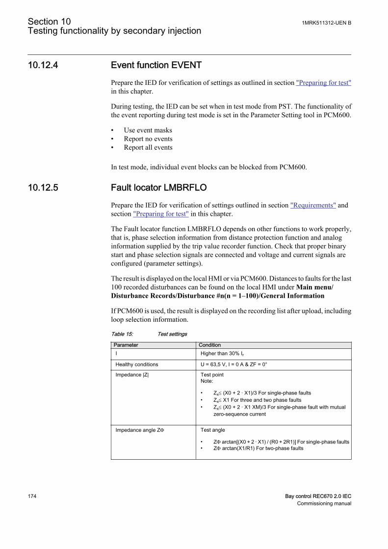
10.12.4 Event function EVENT
Prepare the IED for verification of settings as outlined in section "Preparing for test"in this chapter.
During testing, the IED can be set when in test mode from PST. The functionality ofthe event reporting during test mode is set in the Parameter Setting tool in PCM600.
• Use event masks• Report no events• Report all events
In test mode, individual event blocks can be blocked from PCM600.
10.12.5 Fault locator LMBRFLO
Prepare the IED for verification of settings outlined in section "Requirements" andsection "Preparing for test" in this chapter.
The Fault locator function LMBRFLO depends on other functions to work properly,that is, phase selection information from distance protection function and analoginformation supplied by the trip value recorder function. Check that proper binarystart and phase selection signals are connected and voltage and current signals areconfigured (parameter settings).
The result is displayed on the local HMI or via PCM600. Distances to faults for the last100 recorded disturbances can be found on the local HMI under Main menu/Disturbance Records/Disturbance #n(n = 1–100)/General Information
If PCM600 is used, the result is displayed on the recording list after upload, includingloop selection information.
Table 15: Test settings
Parameter ConditionI Higher than 30% Ir
Healthy conditions U = 63,5 V, I = 0 A & ZF = 0°
Impedance |Z| Test pointNote:
• Zx£ (X0 + 2 · X1)/3 For single-phase faults• Zx£ X1 For three and two phase faults• Zx£ (X0 + 2 · X1 XM)/3 For single-phase fault with mutual
zero-sequence current
Impedance angle ZF Test angle
• ZF arctan[(X0 + 2 · X1) / (R0 + 2R1)] For single-phase faults• ZF arctan(X1/R1) For two-phase faults
Section 10 1MRK511312-UEN BTesting functionality by secondary injection
174 Bay control REC670 2.0 IECCommissioning manual

10.12.5.1 Measuring the operate limit
1. Set the test point (|Z| fault impedance and ZF impedance phase angle ) for acondition that meets the requirements in table 15.
2. Subject the IED to healthy normal load conditions for at least two seconds.3. Apply a fault condition.
Check that the distance-to-fault value displayed on the HMI complies withequations 46, 47 and 48
pZxX1------- 100×=
EQUATION123 V1 EN (Equation 46)
in % for two- and three-phase faults
x3 Zp 100
X0 2 X1×
= ×+ ×
EQUATION124 V1 EN (Equation 47)
in % for single-phase-to-earth faults
p3 Z× x
X0 2 X1 XM±×+--------------------------------------------- 100×=
EQUATION125 V1 EN (Equation 48)
in % for single-phase-to-earth faults with mutual zero sequence current.
Where:
p = the expected value of a distance to fault in percent
Zx = set test point on the test set
X0 = set zero-sequence reactance of a line
X1 = set positive-sequence reactance of a line
XM = set mutual zero-sequence impedance of a line
10.12.5.2 Completing the test
Continue to test another function or end the test by changing the TestMode setting toOff. Restore connections and settings to their original values, if they were changed fortesting purposes.
10.12.6 Limit counter L4UFCNT
The Limit counter function L4UFCNT can be tested by connecting a binary input tothe counter and applying pulses to the counter. The speed of the pulses must notexceed the cycle time of the function. Normally the counter will be tested when testingthe function that the counter is connected to, such as the trip function. When the
1MRK511312-UEN B Section 10Testing functionality by secondary injection
Bay control REC670 2.0 IEC 175Commissioning manual
function is configured, test it together with the function that operates it. Trig thefunction and check that the counter result corresponds to the number of operations.
10.12.6.1 Completing the test
Continue to test another function or end the test by changing the Test mode setting toOff. Restore connections and settings to their original values, if they were changed fortesting purposes.
10.13 Metering
10.13.1 Pulse-counter logic PCFCNT
The test of the Pulse-counter logic function PCFCNT requires the Parameter Settingtool in PCM600 or an appropriate connection to the local HMI with the necessaryfunctionality. A known number of pulses with different frequencies are connected tothe pulse counter input. The test should be performed with settings Operation = On orOperation = Off and the function blocked or unblocked. The pulse counter value isthen checked in PCM600 or on the local HMI.
10.13.2 Function for energy calculation and demand handlingETPMMTR
Prepare the IED for verification of settings as outlined in section ”Overview “ andsection ”Preparing for test“ in this chapter.
10.13.2.1 Verifying the settings
Common test equipment can be used to determine the injection of current and voltageand time measurement.
Verification of EAFACC & ERFACC output
1. Connect the test set for injection of three-phase currents and three phase voltageto the appropriate current and voltage terminals of the IED.
2. Ensure the instantaneous values of active and reactive power from CVMMXNfunction block are connected to ETPMMTR function block active and reactivepower inputs.
3. Enable the EnaAcc setting and set tEnergy as 1 minute.4. Activate the STARTACC input and supply the IED with three phase currents and
voltages at their rated value.5. Check that the ACCINPRG signal appears continuously.6. Note the EAFACC and ERFACCvalue after 1 minute and compare it with
calculated energy value.
Section 10 1MRK511312-UEN BTesting functionality by secondary injection
176 Bay control REC670 2.0 IECCommissioning manual

7. Similarly check after each 1 minute whether the calculated integrated energyvalue and EAFACC and ERFACC outputs are matching.
8. After some time (multiple of minute) remove the current and voltage input fromCVMMXN function block.
9. Check the EAFACC and ERFACC output in the next 1 minute cycle for theretaining the same value.
10. Activate STOPACC input after some time and supply the IED with same currentand voltage.
11. Check that the ACCINPRG signal disappears immediately and EAFACC andERFACC outputs also stop updating.
12. Similarly the testing can be done for EAFACC and ERFACC outputs by changingthe power inputs directions through direction settings.
Verification of MAXPAFD & MAXPRFD outputs
1. Repeat the above test steps 1 to 2.2. Set tEnergy setting as 1 minute and supply the IED with three phase currents and
voltages at their rated value till 1 minute.3. Check the MAXPAFD and MAXPRFD outputs after 1 minute and compare it with
last 1 minute average power values.4. Increase either three phase current or voltage above the last 1 minute value.5. After 1 minute check the MAXPAFD and MAXPRFD whether it is showing the last
1 minute average power value as maximum.6. Next 1 minute cycle reduce the current or voltage below previous value.7. Check after 1 minute whether the MAXPAFD and MAXPRFD outputs are retaining
the old maximum value.8. Similarly the testing can be done for MAXPAFD and MAXPRFD outputs by
changing the power inputs directions through direction settings.
Verification of EAFALM & ERFALM outputs
1. Repeat the above test steps 1 to 2.2. Set tEnergy setting as 1 minute and supply the IED with three phase currents and
voltages at their rated value till 1 minute.3. Ensure that the active and reactive energy values are less than the EALim and
ERLim setting default values respectively.4. Check that EAFALM and ERFALM are low.5. Increase the supply currents or voltage in next 1 minute cycle such that the active
or reactive energy values are greater than the EALim and ERLim setting defaultvalues respectively.
6. Check that EAFALM and ERFALM are high after 1 minute.7. Similarly the testing can be done for EARALM and ERRALM outputs by changing
the power inputs directions through direction settings.
1MRK511312-UEN B Section 10Testing functionality by secondary injection
Bay control REC670 2.0 IEC 177Commissioning manual
10.13.2.2 Completing the test
Continue to test another function or end the test by changing the TestMode setting toOff. Restore connections and settings to their original values, if they were changed fortesting purposes.
10.14 Station communication
10.14.1 Multiple command and transmit MULTICMDRCV /MULTICMDSND
The multiple command and transmit function (MULTICMDRCV /MULTICMDSND) is only applicable for horizontal communication.
Test of the multiple command function block and multiple transmit is recommendedto be performed in a system, that is, either in a complete delivery system as anacceptance test (FAT/SAT) or as parts of that system, because the command functionblocks are connected in a delivery-specific way between bays and the station level andtransmit.
Command and transmit function blocks included in the operation of different built-infunctions must be tested at the same time as their corresponding functions.
10.15 Remote communication
10.15.1 Binary signal transfer BinSignReceive, BinSignTransm
Prepare the IED for verification of settings as outlined in section "Preparing the IEDto verify settings".
To perform a test of Binary signal transfer function (BinSignReceive/BinSignTransm), the hardware (LDCM) and binary input and output signals totransfer must be configured as required by the application.
There are two types of internal self supervision of BinSignReceive/BinSignTransm
• The I/O-circuit board is supervised as an I/O module. For example it generatesFAIL if the board is not inserted. I/O-modules not configured are not supervised.
• The communication is supervised and the signal COMFAIL is generated if acommunication error is detected.
Status for inputs and outputs as well as self-supervision status are available from thelocal HMI under
Section 10 1MRK511312-UEN BTesting functionality by secondary injection
178 Bay control REC670 2.0 IECCommissioning manual

• Self-supervision status: Main menu/Diagnostics/Internal events• Status for inputs and outputs: Main menu/Test/Function status, browse to the
function group of interest.• Remote communication related signals: Main menu/Test/Function status/
Communication/Remote communication
Test the correct functionality by simulating different kind of faults. Also check thatsent and received data is correctly transmitted and read.
A test connection is shown in figure 24. A binary input signal (BI) at End1 isconfigured to be transferred through the communication link to End2. At End2 thereceived signal is configured to control a binary output (BO). Check at End2 that theBI signal is received and the BO operates.
Repeat the test for all the signals configured to be transmitted over the communicationlink.
IEC07000188 V1 EN
Figure 24: Test of RTC with I/O
10.16 Basic IED functions
10.16.1 Parameter setting group handling SETGRPS
Prepare the IED for verification of settings as outlined in section "Preparing for test"in this chapter.
1MRK511312-UEN B Section 10Testing functionality by secondary injection
Bay control REC670 2.0 IEC 179Commissioning manual
10.16.1.1 Verifying the settings
1. Check the configuration of binary inputs that control the selection of the activesetting group.
2. Browse to the ActiveGroup menu to achieve information about the activesetting group.The ActiveGroup menu is located on the local HMI underMain menu/Test/Function status/Setting groups/ActiveGroup
3. Connect the appropriate dc voltage to the corresponding binary input of the IEDand observe the information presented on the local HMI.The displayed information must always correspond to the activated input.
4. Check that the corresponding output indicates the active group.Operating procedures for the PC aided methods of changing the active settinggroups are described in the corresponding PCM600 documents and instructionsfor the operators within the SCS are included in the SCS documentation.
10.16.1.2 Completing the test
Continue to test another function or end the test by changing the TestMode setting toOff. Restore connections and settings to their original values, if they were changed fortesting purposes.
10.17 Exit test mode
The following procedure is used to return to normal operation.
After exiting the IED test mode, make sure that the MU is returned tonormal mode.
1. Navigate to the test mode folder.2. Change the On setting to Off. Press the 'E' key and the left arrow key.3. Answer YES, press the 'E' key and exit the menus.
Section 10 1MRK511312-UEN BTesting functionality by secondary injection
180 Bay control REC670 2.0 IECCommissioning manual
Section 11 Primary injection testing
Whenever it becomes necessary to work on primary equipment, it isessential that all the necessary switching, locking, earthing and safetyprocedures are observed and obeyed in a rigid and formalized manner.Operating and testing procedures should be strictly followed in orderto avoid exposure to live equipment.
A test with primary current through the protected zone is usually a final check that thecurrent circuits are correctly connected to the IED protection scheme. It is importantto have an appropriate source, which is able to inject sufficient current in the primarycircuit in order to distinguish between noise and real injected current. Therefore it isrecommended that the injection current should be at least 10% of rated CT primarycurrent.
11.1 Transformer Voltage Control ATCC
11.1.1 Load drop compensation function, LDC
The load drop compensation function can be tested directly with operational currents,in other words, with the power transformer in service and loaded.
When the system is carrying load there is a difference between the busbar voltage(UB) and the voltage at the load point (UL). This difference is load dependent and canbe compensated by the ATCC function.
The load current is fed into the ATCC function where parameters corresponding to theline data for resistance and inductance are set. The voltage drop calculated by the LDCis proportional to the voltage drop in the system up to the load point.
In the IED, this voltage is subtracted from the measured busbar voltage (UB) and theresult, corresponding to the voltage at the load point (UL) is presented to the ATCCfunction for the purposes of voltage regulation. This voltage will be lower (if resistiveor inductive load current is applied) than the Uset voltage and ATCC increases thevoltage in order to achieve the correct system voltage at the load point.
1. Confirm the PST settings for Rline and Xline.If the function LDC is set to Zero, this test is omitted.
2. Open the voltage control display on the LHMI in Main Menu/Control/Commands/TransformerVoltageControl (ATCC, 90).
1MRK511312-UEN B Section 11Primary injection testing
Bay control REC670 2.0 IEC 181Commissioning manual
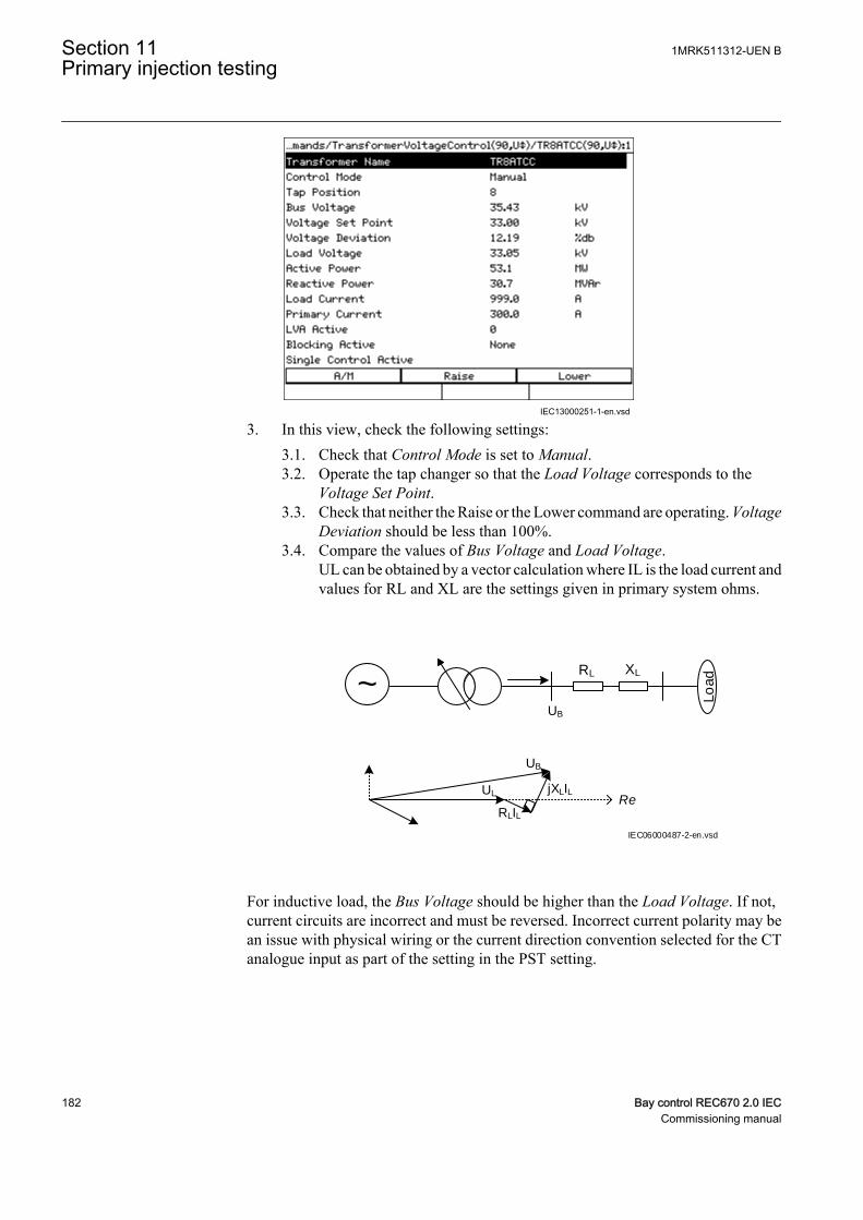
IEC13000251-1-en.vsd
3. In this view, check the following settings:3.1. Check that Control Mode is set to Manual.3.2. Operate the tap changer so that the Load Voltage corresponds to the
Voltage Set Point.3.3. Check that neither the Raise or the Lower command are operating. Voltage
Deviation should be less than 100%.3.4. Compare the values of Bus Voltage and Load Voltage.
UL can be obtained by a vector calculation where IL is the load current andvalues for RL and XL are the settings given in primary system ohms.
~Lo
adRL XL
UB
UL
UB
RLIL
jXLILRe
IEC06000487-2-en.vsd
For inductive load, the Bus Voltage should be higher than the Load Voltage. If not,current circuits are incorrect and must be reversed. Incorrect current polarity may bean issue with physical wiring or the current direction convention selected for the CTanalogue input as part of the setting in the PST setting.
Section 11 1MRK511312-UEN BPrimary injection testing
182 Bay control REC670 2.0 IECCommissioning manual
11.1.2 Voltage control of Parallel Transformers
In parallel operation, each transformer protection IED must be connected to the stationcommunication bus for data exchange. The following procedure assumes that thenecessary pre-configuration in the Parameter Setting tool and the Signal Matrix toolhas been performed and tested to enable data exchange between IEDs or betweeninstances of voltage control in the same IED.
For parallel operation, it is also recommended to confirm the setting for the generalparallel arrangement of transformers in Main menu/Settings/Setting group N/Control/TransformerVoltageControl(ATCC,90)/TR8ATCC:x/ParCtrl.General parallel arrangement of transformers are defined by setting TnRXOP to On orOff. The following rules are applicable for the settings of T1RXOP – T8RXOP.
• In each instance of TR8ATCC, set all TnRXOP parameters corresponding to theconnected IEDs to On except the parameter corresponding to the IED itself. Forexample, do not set T1RXOP to On in IED T1 or T2RXOP to On in IED T2.
For example, if IEDs T1, T2 and T3 are connected,
• In instance 1 of TR8ATCC, set T2RXOP and T3RXOP to On.• In instance 2 of TR8ATCC, set T1RXOP and T3RXOP to On.• In instance 3 of TR8ATCC, set T1RXOP and T2RXOP to On.
11.1.3 Minimum Circulating Current (MCC) method
Voltage control of parallel transformers with the circulating current method meansminimizing the circulating current at a given voltage target value. The busbar voltage(UB) is measured individually for each transformer in the parallel group by itsassociated TR8ATCC function. These measured values are then exchanged betweenthe transformers, and in each TR8ATCC block, the mean value of all UB values iscalculated. The resulting value UBmean is then used in each IED instead of UB for thevoltage regulation.
1. Check the overcurrent blocking level (Iblock) in Main menu/Settings/Generalsettings/Control/TransformerVoltageControl(ATCC,90)/TR8ATCC:x/TCCtrl/Iblock.
2. Check that the circulating current blocking (OperCCBlock) is set On, and thecheck the correct settings for circulating current limit (CircCurLimit) in Mainmenu/Settings/General settings/Control/TransformerVoltageControl(ATCC,90)/TR8ATCC:x/ParCtrl/CircCurrLimit.
1MRK511312-UEN B Section 11Primary injection testing
Bay control REC670 2.0 IEC 183Commissioning manual
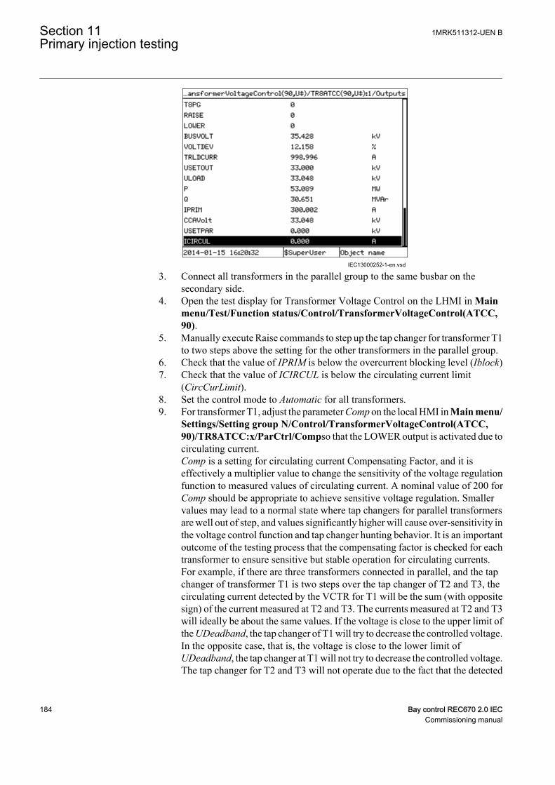
IEC13000252-1-en.vsd
3. Connect all transformers in the parallel group to the same busbar on thesecondary side.
4. Open the test display for Transformer Voltage Control on the LHMI in Mainmenu/Test/Function status/Control/TransformerVoltageControl(ATCC,90).
5. Manually execute Raise commands to step up the tap changer for transformer T1to two steps above the setting for the other transformers in the parallel group.
6. Check that the value of IPRIM is below the overcurrent blocking level (Iblock)7. Check that the value of ICIRCUL is below the circulating current limit
(CircCurLimit).8. Set the control mode to Automatic for all transformers.9. For transformer T1, adjust the parameter Comp on the local HMI in Main menu/
Settings/Setting group N/Control/TransformerVoltageControl(ATCC,90)/TR8ATCC:x/ParCtrl/Compso that the LOWER output is activated due tocirculating current.Comp is a setting for circulating current Compensating Factor, and it iseffectively a multiplier value to change the sensitivity of the voltage regulationfunction to measured values of circulating current. A nominal value of 200 forComp should be appropriate to achieve sensitive voltage regulation. Smallervalues may lead to a normal state where tap changers for parallel transformersare well out of step, and values significantly higher will cause over-sensitivity inthe voltage control function and tap changer hunting behavior. It is an importantoutcome of the testing process that the compensating factor is checked for eachtransformer to ensure sensitive but stable operation for circulating currents.For example, if there are three transformers connected in parallel, and the tapchanger of transformer T1 is two steps over the tap changer of T2 and T3, thecirculating current detected by the VCTR for T1 will be the sum (with oppositesign) of the current measured at T2 and T3. The currents measured at T2 and T3will ideally be about the same values. If the voltage is close to the upper limit ofthe UDeadband, the tap changer of T1 will try to decrease the controlled voltage.In the opposite case, that is, the voltage is close to the lower limit ofUDeadband, the tap changer at T1 will not try to decrease the controlled voltage.The tap changer for T2 and T3 will not operate due to the fact that the detected
Section 11 1MRK511312-UEN BPrimary injection testing
184 Bay control REC670 2.0 IECCommissioning manual
circulating current will be half of the current detected at T1. The setting of theparameter Comp then might need to be increased a little. At least one tap changerstep difference between the different transformers should be allowed in order toavoid the tap changers to operate too often. If the allowed difference is, forexample, two steps, the tap changer shall be stepped up three steps when settingthe parameter Comp.
10. Set the Comp parameter for T2 and T3 in the same manner as for T1. Accordingto the described procedure when the tap changer of one transformer is two stepsabove the others, it shall automatically step down. When there are only twotransformers in the group either shall one step down or the other step updepending on the voltage level at the ATCC.
11.1.4 Master Follower (MF) method
The Master Follower method requires a Master to be nominated in a parallel group. Itis responsible for measuring secondary bus voltage and executing commands to raiseand lower tap changers, which are repeated by Follower transformers in the group.
1. Confirm the voltage blocking levels OVPartBK and UVPpartBK in Mainmenu/Settings/General settings/Control/TransformerVoltageControl(ATCC,90)/TR8ATCC:x/Voltage/Umax,Umin.
2. Check that MFMode is set to Follow Tap or Follow Cmd in Main menu/Settings/General settings/Control/TransformerVoltageControl(ATCC,90)/TR8ATCC:x/MFMode.If this setting is Follow Tap, all Follower transformers shall match the actual tapsetting of the Master, while Follow Cmd requires that Follower transformersfollow the RAISE and LOWER commands executed by the Master.
3. Confirm the maximum difference in tap positions for parallel transformers. Thenumber of taps is determined by the setting in the Parameter Setting tool underMain menu/Settings/Setting group N/Control/TransformerVoltageControl(ATCC,90)/TR8ATCC:x/ParCtrl/MFPosDiffLim
4. Connect all transformers in the parallel group to the same busbar on both theprimary and secondary sides.
5. Set the control mode to Manual for each transformer in the parallel control group6. Open the test display for Transformer Voltage Control on the LHMI in Main
menu/Test/Function status/Control/TransformerVoltageControl (ATCC,90).
1MRK511312-UEN B Section 11Primary injection testing
Bay control REC670 2.0 IEC 185Commissioning manual
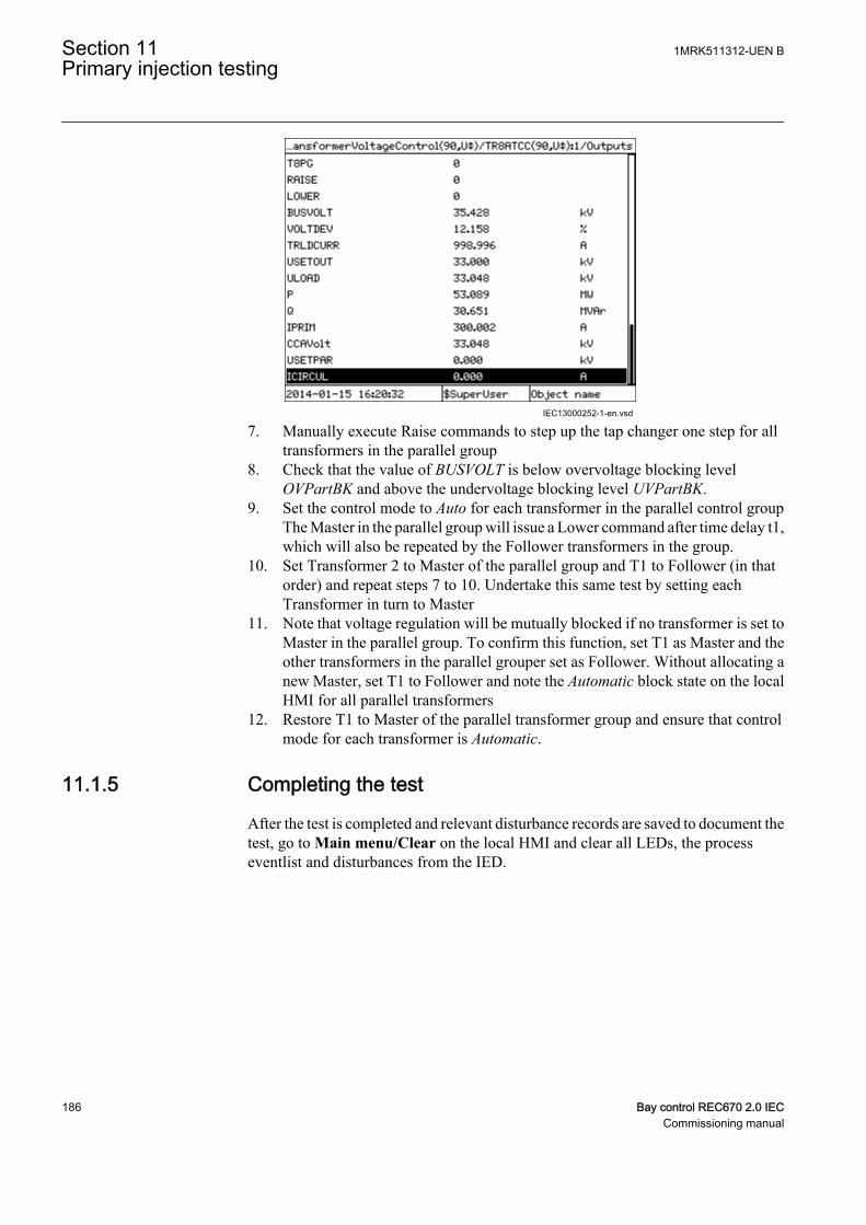
IEC13000252-1-en.vsd
7. Manually execute Raise commands to step up the tap changer one step for alltransformers in the parallel group
8. Check that the value of BUSVOLT is below overvoltage blocking levelOVPartBK and above the undervoltage blocking level UVPartBK.
9. Set the control mode to Auto for each transformer in the parallel control groupThe Master in the parallel group will issue a Lower command after time delay t1,which will also be repeated by the Follower transformers in the group.
10. Set Transformer 2 to Master of the parallel group and T1 to Follower (in thatorder) and repeat steps 7 to 10. Undertake this same test by setting eachTransformer in turn to Master
11. Note that voltage regulation will be mutually blocked if no transformer is set toMaster in the parallel group. To confirm this function, set T1 as Master and theother transformers in the parallel grouper set as Follower. Without allocating anew Master, set T1 to Follower and note the Automatic block state on the localHMI for all parallel transformers
12. Restore T1 to Master of the parallel transformer group and ensure that controlmode for each transformer is Automatic.
11.1.5 Completing the test
After the test is completed and relevant disturbance records are saved to document thetest, go to Main menu/Clear on the local HMI and clear all LEDs, the processeventlist and disturbances from the IED.
Section 11 1MRK511312-UEN BPrimary injection testing
186 Bay control REC670 2.0 IECCommissioning manual
Section 12 Commissioning and maintenance of thefault clearing system
12.1 Commissioning tests
During commissioning all protection functions shall be verified with the settingvalues used at each plant. The commissioning tests must include verification of allcircuits by green-lining the circuit diagrams and the configuration diagrams for theused functions.
Further, the settings for protection functions are tested and recorded carefully asoutlined for the future periodic maintenance tests.
The final testing includes primary verification of all directional functions where loadcurrents is checked on the local HMI and in PCM600. The amplitudes and angles ofall currents and voltages should be checked and the symmetry verified.
Directional functions have information about the measured direction and, forexample, measured impedance. These values must be checked and verified as correctwith the export or import of power available.
Finally, final trip tests must be performed. This involves activation of protectionfunctions or tripping outputs with the circuit breaker closed and the tripping of thebreaker verified. When several breakers are involved, each breaker must be checkedindividually and it must be verified that the other involved breakers are not tripped atthe same time.
12.2 Periodic maintenance tests
The periodicity of all tests depends on several factors, for example the importance ofthe installation, environmental conditions, simple or complex equipment, static orelectromechanical IEDs, and so on.
The normal maintenance praxis of the user should be followed. However, ABB'srecommendation is as follows:
Every second to third year
• Visual inspection of all equipment.• Removal of dust on ventilation louvres and IEDs if necessary.• Periodic maintenance test for protection IEDs of object where no redundant
protections are provided.
1MRK511312-UEN B Section 12Commissioning and maintenance of the fault clearing system
Bay control REC670 2.0 IEC 187Commissioning manual

Every four to six years
• Periodic maintenance test for protection IEDs of objects with redundantprotection system.
First maintenance test should always be carried out after the first halfyear of service.
When protection IEDs are combined with built-in control, the testinterval can be increased drastically, up to for instance 15 years,because the IED continuously reads service values, operates thebreakers, and so on.
12.2.1 Visual inspection
Prior to testing, the protection IEDs should be inspected to detect any visible damagethat may have occurred (for example, dirt or moisture deposits, overheating).
Make sure that all IEDs are equipped with covers.
12.2.2 Maintenance tests
To be made after the first half year of service, then with the cycle as proposed aboveand after any suspected maloperation or change of the IED setting.
Testing of protection IEDs shall preferably be made with the primary circuit de-energized. The IED cannot protect the circuit during testing. Trained personnel maytest one IED at a time on live circuits where redundant protection is installed and de-energization of the primary circuit is not allowed.
ABB protection IEDs are preferably tested by aid of components from theCOMBITEST testing system described in information B03-9510 E. Maincomponents are RTXP 8/18/24 test switch usually located to the left in each protectionIED and RTXH 8/18/24 test handle, which is inserted in test switch at secondarytesting. All necessary operations such as opening of trip circuits, short-circuiting ofcurrent circuits and opening of voltage circuits are automatically performed in theright order to allow for simple and safe secondary testing even with the object inservice.
12.2.2.1 Preparation
Before starting maintenance testing, the test engineers should scrutinize applicablecircuit diagrams and have the following documentation available:
Section 12 1MRK511312-UEN BCommissioning and maintenance of the fault clearing system
188 Bay control REC670 2.0 IECCommissioning manual
• Test instructions for protection IEDs to be tested• Test records from previous commissioning and maintenance tests• List of valid settings• Blank test records to fill in measured values
12.2.2.2 Recording
It is of utmost importance to carefully record the test results. Special test sheetscovering the frequency of test, date of test and achieved test values should be used.IED setting list and protocols from previous tests should be available and all resultsshould be compared for differences. At component failures, spare equipment is usedand set to the requested value. A note of the exchange is made and the new measuredvalues are recorded. Test records for several years of testing should be stored in acommon file for a station, or a part of a station, to give a simple overview of the periodof testing and achieved test values. These test records are valuable when analysis ofservice disturbances shall be done.
12.2.2.3 Secondary injection
The periodic maintenance test is done by secondary injection from a portable test set.Each protection shall be tested according to the secondary injection test informationfor the specific protection IED. Only the setting values adopted shall be checked foreach protection function. If the discrepancy between obtained value and requested setvalue is too big the setting should be adjusted, the new value recorded and a noteshould be made in the test record.
12.2.2.4 Alarm test
When inserting the test handle the alarm and event signalling is normally blocked.This is done in the IED by setting the event reporting to Off during the test. This canbe done when the test handle is inserted or the IED is set to test mode from the localHMI. At the end of the secondary injection test it should be checked that the event andalarm signalling is correct by activating the events and performing some selected tests.
12.2.2.5 Self supervision check
Once secondary testing has been completed, it should be checked that no self-supervision signals are activated continuously or sporadically. Especially check thetime synchronization system, GPS or other, and communication signals, both stationcommunication and remote communication.
12.2.2.6 Trip circuit check
When the protection IED undergoes an operational check, a tripping pulse is normallyobtained on one or more of the output contacts and preferably on the test switch. Thehealthy circuit is of utmost importance for the protection operation. If the circuit is notprovided with a continuous trip-circuit supervision, it is possible to check that circuit
1MRK511312-UEN B Section 12Commissioning and maintenance of the fault clearing system
Bay control REC670 2.0 IEC 189Commissioning manual

is really closed when the test-plug handle has been removed by using a high-ohmicvoltmeter and measuring between the plus and the trip output on the panel. Themeasurement is then done through the trip coil of the circuit breaker and therefore thecomplete trip circuit is checked.
Note that the breaker must be closed.
Please observe that the test system does not provide built-in securityduring this test. If the instrument should be set on Amp instead ofVolts, the circuit breaker naturally is tripped, therefore, great care isnecessary.
Trip circuit from trip IEDs to circuit breaker is often supervised by trip-circuitsupervision. It can then be checked that a circuit is healthy by opening tripping outputterminals in the cubicle. When the terminal is opened, an alarm shall be achieved onthe signal system after a delay of some seconds.
Remember to close the circuit directly after the test and tighten theterminal carefully.
12.2.2.7 Measurement of service currents
After a maintenance test it is recommended to measure the service currents and servicevoltages recorded by the protection IED. The service values are checked on the localHMI or in PCM600. Ensure that the correct values and angles between voltages andcurrents are recorded. Also check the direction of directional functions such asDistance and directional overcurrent functions.
For transformer differential protection, the achieved differential current value isdependent on the tap changer position and can vary between less than 1% up toperhaps 10% of rated current. For line differential functions, the capacitive chargingcurrents can normally be recorded as a differential current.
The zero-sequence current to earth-fault protection IEDs should be measured. Thecurrent amounts normally very small but normally it is possible to see if the currentcircuit is "alive".
The neutral-point voltage to an earth-fault protection IED is checked. The voltage isnormally 0.1 to 1V secondary. However, voltage can be considerably higher due toharmonics. Normally a CVT secondary can have around 2.5 - 3% third-harmonicvoltage.
Section 12 1MRK511312-UEN BCommissioning and maintenance of the fault clearing system
190 Bay control REC670 2.0 IECCommissioning manual
12.2.2.8 Restoring
Maintenance is very important to improve the availability of the protection system bydetecting failures before the protection is required to operate. There is however littlepoint in testing healthy equipment and then putting it back into service with an openterminal, with a removed fuse or open miniature circuit breaker with an openconnection, wrong setting, and so on.
Thus a list should be prepared of all items disturbed during test so that all can be putback into service quickly and without overlooking something. It should be put backinto service item by item and signed by the responsible engineer.
1MRK511312-UEN B Section 12Commissioning and maintenance of the fault clearing system
Bay control REC670 2.0 IEC 191Commissioning manual

192
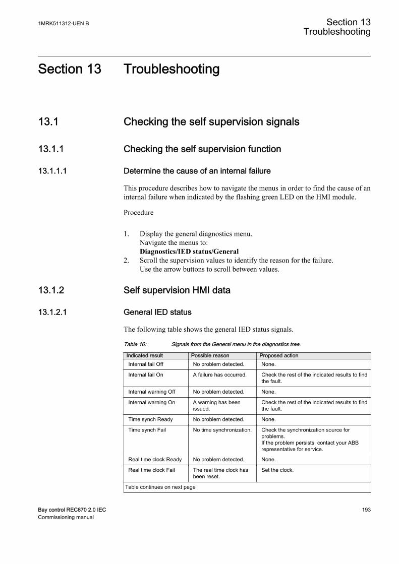
Section 13 Troubleshooting
13.1 Checking the self supervision signals
13.1.1 Checking the self supervision function
13.1.1.1 Determine the cause of an internal failure
This procedure describes how to navigate the menus in order to find the cause of aninternal failure when indicated by the flashing green LED on the HMI module.
Procedure
1. Display the general diagnostics menu.Navigate the menus to:Diagnostics/IED status/General
2. Scroll the supervision values to identify the reason for the failure.Use the arrow buttons to scroll between values.
13.1.2 Self supervision HMI data
13.1.2.1 General IED status
The following table shows the general IED status signals.
Table 16: Signals from the General menu in the diagnostics tree.
Indicated result Possible reason Proposed actionInternal fail Off No problem detected. None.
Internal fail On A failure has occurred. Check the rest of the indicated results to findthe fault.
Internal warning Off No problem detected. None.
Internal warning On A warning has beenissued.
Check the rest of the indicated results to findthe fault.
Time synch Ready No problem detected. None.
Time synch Fail No time synchronization. Check the synchronization source forproblems.If the problem persists, contact your ABBrepresentative for service.
Real time clock Ready No problem detected. None.
Real time clock Fail The real time clock hasbeen reset.
Set the clock.
Table continues on next page
1MRK511312-UEN B Section 13Troubleshooting
Bay control REC670 2.0 IEC 193Commissioning manual
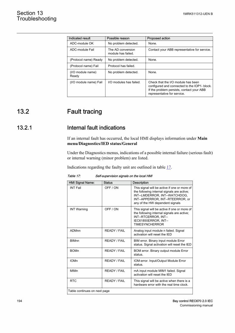
Indicated result Possible reason Proposed actionADC-module OK No problem detected. None.
ADC-module Fail The AD conversionmodule has failed.
Contact your ABB representative for service.
(Protocol name) Ready No problem detected. None.
(Protocol name) Fail Protocol has failed.
(I/O module name)Ready
No problem detected. None.
(I/O module name) Fail I/O modules has failed. Check that the I/O module has beenconfigured and connected to the IOP1- block.If the problem persists, contact your ABBrepresentative for service.
13.2 Fault tracing
13.2.1 Internal fault indications
If an internal fault has occurred, the local HMI displays information under Mainmenu/Diagnostics/IED status/General
Under the Diagnostics menus, indications of a possible internal failure (serious fault)or internal warning (minor problem) are listed.
Indications regarding the faulty unit are outlined in table 17.
Table 17: Self-supervision signals on the local HMI
HMI Signal Name: Status DescriptionINT Fail OFF / ON This signal will be active if one or more of
the following internal signals are active;INT--LMDERROR, INT--WATCHDOG,INT--APPERROR, INT--RTEERROR, orany of the HW dependent signals
INT Warning OFF / ON This signal will be active if one or more ofthe following internal signals are active;INT--RTCERROR, INT--IEC61850ERROR, INT--TIMESYNCHERROR
ADMnn READY / FAIL Analog input module n failed. Signalactivation will reset the IED
BIMnn READY / FAIL BIM error. Binary input module Errorstatus. Signal activation will reset the IED
BOMn READY / FAIL BOM error. Binary output module Errorstatus.
IOMn READY / FAIL IOM-error. Input/Output Module Errorstatus.
MIMn READY / FAIL mA input module MIM1 failed. Signalactivation will reset the IED
RTC READY / FAIL This signal will be active when there is ahardware error with the real time clock.
Table continues on next page
Section 13 1MRK511312-UEN BTroubleshooting
194 Bay control REC670 2.0 IECCommissioning manual

HMI Signal Name: Status DescriptionTime Sync READY / FAIL This signal will be active when the source
of the time synchronization is lost, or whenthe time system has to make a time reset.
Application READY / FAIL This signal will be active if one or more ofthe application threads are not in the statethat Runtime Engine expects. The statescan be CREATED, INITIALIZED,RUNNING, etc.
RTE READY / FAIL This signal will be active if the RuntimeEngine failed to do some actions with theapplication threads. The actions can beloading of settings or parameters forcomponents, changing of setting groups,loading or unloading of applicationthreads.
IEC61850 READY / FAIL This signal will be active if the IEC61850stack did not succeed in some actions likereading IEC61850 configuration, startupetc.
LMD READY / FAIL LON network interface, MIP/DPS, is in anunrecoverable error state.
LDCMxxx READY / FAIL Line Differential Communication Errorstatus
OEM READY / FAIL Optical Ethernet Module error status.
Also the internal signals, such as INT--FAIL and INT--WARNING can be connectedto binary output contacts for signalling to a control room.
In the IED Status - Information, the present information from the self-supervisionfunction can be viewed. Indications of failure or warnings for each hardware moduleare provided, as well as information about the external time synchronization and theinternal clock. All according to table 17. Loss of time synchronization can beconsidered as a warning only. The IED has full functionality without timesynchronization.
13.2.2 Using front-connected PC
When an internal fault has occurred, extensive information about the fault can beretrieved from the list of internal events available in the SMS part:
TRM-STAT TermStatus - Internal Events
The list of internal events provides valuable information, which can be used duringcommissioning and fault tracing.
The internal events are time tagged with a resolution of 1ms and stored in a list. Thelist can store up to 40 events. The list is based on the FIFO principle, when it is full,the oldest event is overwritten. The list cannot be cleared and its content cannot beerased.
1MRK511312-UEN B Section 13Troubleshooting
Bay control REC670 2.0 IEC 195Commissioning manual
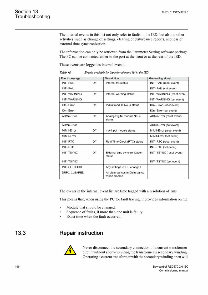
The internal events in this list not only refer to faults in the IED, but also to otheractivities, such as change of settings, clearing of disturbance reports, and loss ofexternal time synchronization.
The information can only be retrieved from the Parameter Setting software package.The PC can be connected either to the port at the front or at the rear of the IED.
These events are logged as internal events.
Table 18: Events available for the internal event list in the IED
Event message: Description Generating signal:INT--FAIL Off Internal fail status INT--FAIL (reset event)
INT--FAIL INT--FAIL (set event)
INT--WARNING Off Internal warning status lNT--WARNING (reset event)
INT--WARNING lNT--WARNING (set event)
IOn--Error Off In/Out module No. n status IOn--Error (reset event)
IOn--Error IOn--Error (set event)
ADMn-Error Off Analog/Digital module No. nstatus
ADMn-Error (reset event)
ADMn-Error ADMn-Error (set event)
MIM1-Error Off mA-input module status MIM1-Error (reset event)
MIM1-Error MIM1-Error (set event)
INT--RTC Off Real Time Clock (RTC) status INT--RTC (reset event)
INT--RTC INT--RTC (set event)
INT--TSYNC Off External time synchronizationstatus
INT--TSYNC (reset event)
INT--TSYNC INT--TSYNC (set event)
INT--SETCHGD Any settings in IED changed
DRPC-CLEARED All disturbances in Disturbancereport cleared
The events in the internal event list are time tagged with a resolution of 1ms.
This means that, when using the PC for fault tracing, it provides information on the:
• Module that should be changed.• Sequence of faults, if more than one unit is faulty.• Exact time when the fault occurred.
13.3 Repair instruction
Never disconnect the secondary connection of a current transformercircuit without short-circuiting the transformer’s secondary winding.Operating a current transformer with the secondary winding open will
Section 13 1MRK511312-UEN BTroubleshooting
196 Bay control REC670 2.0 IECCommissioning manual

cause a massive potential build up that may damage the transformerand may cause injuries to humans.
Never connect or disconnect a wire and/or a connector to or from aIED during normal service. Hazardous voltages and currents arepresent that may be lethal. Operation may be disrupted and IED andmeasuring circuitry may be damaged.
An alternative is to open the IED and send only the faulty circuit board to ABB forrepair. When a printed circuit board is sent to ABB, it must always be placed in ametallic, ESD-proof, protection bag. The user can also purchase separate replacementmodules.
Strictly follow the company and country safety regulations.
Most electronic components are sensitive to electrostatic discharge and latent damagemay occur. Please observe usual procedures for handling electronics and also use anESD wrist strap. A semi-conducting layer must be placed on the workbench andconnected to earth.
Disassemble and reassemble the IED accordingly:
1. Switch off the dc supply.2. Short-circuit the current transformers and disconnect all current and voltage
connections from the IED.3. Disconnect all signal wires by removing the female connectors.4. Disconnect the optical fibers.5. Unscrew the main back plate of the IED.6. If the transformer module is to be changed:
• Remove the IED from the panel if necessary.• Remove the rear plate of the IED.• Remove the front plate.• Remove the screws of the transformer input module, both front and rear.
7. Pull out the faulty module.8. Check that the new module has a correct identity number.9. Check that the springs on the card rail are connected to the corresponding metallic
area on the circuit board when the new module is inserted.10. Reassemble the IED.
If the IED has been calibrated with the system inputs, the calibration procedure mustbe performed again to maintain the total system accuracy.
1MRK511312-UEN B Section 13Troubleshooting
Bay control REC670 2.0 IEC 197Commissioning manual

13.4 Repair support
If an IED needs to be repaired, the whole IED must be removed and sent to an ABBLogistic Center. Before returning the material, an inquiry must be sent to the ABBLogistic Center.
e-mail: [email protected]
13.5 Maintenance
The IED is self-supervised. No special maintenance is required.
Instructions from the power network company and other maintenance directives validfor maintenance of the power system must be followed.
Section 13 1MRK511312-UEN BTroubleshooting
198 Bay control REC670 2.0 IECCommissioning manual

Section 14 Glossary
AC Alternating current
ACC Actual channel
ACT Application configuration tool within PCM600
A/D converter Analog-to-digital converter
ADBS Amplitude deadband supervision
ADM Analog digital conversion module, with timesynchronization
AI Analog input
ANSI American National Standards Institute
AR Autoreclosing
ASCT Auxiliary summation current transformer
ASD Adaptive signal detection
ASDU Application service data unit
AWG American Wire Gauge standard
BBP Busbar protection
BFOC/2,5 Bayonet fibre optic connector
BFP Breaker failure protection
BI Binary input
BIM Binary input module
BOM Binary output module
BOS Binary outputs status
BR External bistable relay
BS British Standards
BSR Binary signal transfer function, receiver blocks
BST Binary signal transfer function, transmit blocks
C37.94 IEEE/ANSI protocol used when sending binary signalsbetween IEDs
CAN Controller Area Network. ISO standard (ISO 11898) forserial communication
CB Circuit breaker
CBM Combined backplane module
1MRK511312-UEN B Section 14Glossary
Bay control REC670 2.0 IEC 199Commissioning manual
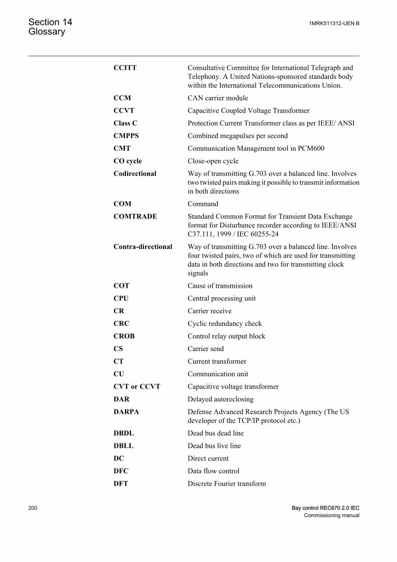
CCITT Consultative Committee for International Telegraph andTelephony. A United Nations-sponsored standards bodywithin the International Telecommunications Union.
CCM CAN carrier module
CCVT Capacitive Coupled Voltage Transformer
Class C Protection Current Transformer class as per IEEE/ ANSI
CMPPS Combined megapulses per second
CMT Communication Management tool in PCM600
CO cycle Close-open cycle
Codirectional Way of transmitting G.703 over a balanced line. Involvestwo twisted pairs making it possible to transmit informationin both directions
COM Command
COMTRADE Standard Common Format for Transient Data Exchangeformat for Disturbance recorder according to IEEE/ANSIC37.111, 1999 / IEC 60255-24
Contra-directional Way of transmitting G.703 over a balanced line. Involvesfour twisted pairs, two of which are used for transmittingdata in both directions and two for transmitting clocksignals
COT Cause of transmission
CPU Central processing unit
CR Carrier receive
CRC Cyclic redundancy check
CROB Control relay output block
CS Carrier send
CT Current transformer
CU Communication unit
CVT or CCVT Capacitive voltage transformer
DAR Delayed autoreclosing
DARPA Defense Advanced Research Projects Agency (The USdeveloper of the TCP/IP protocol etc.)
DBDL Dead bus dead line
DBLL Dead bus live line
DC Direct current
DFC Data flow control
DFT Discrete Fourier transform
Section 14 1MRK511312-UEN BGlossary
200 Bay control REC670 2.0 IECCommissioning manual
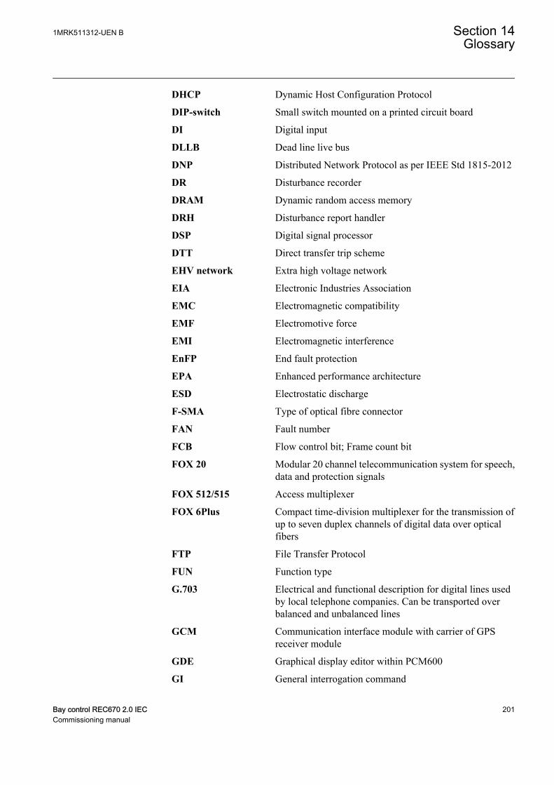
DHCP Dynamic Host Configuration Protocol
DIP-switch Small switch mounted on a printed circuit board
DI Digital input
DLLB Dead line live bus
DNP Distributed Network Protocol as per IEEE Std 1815-2012
DR Disturbance recorder
DRAM Dynamic random access memory
DRH Disturbance report handler
DSP Digital signal processor
DTT Direct transfer trip scheme
EHV network Extra high voltage network
EIA Electronic Industries Association
EMC Electromagnetic compatibility
EMF Electromotive force
EMI Electromagnetic interference
EnFP End fault protection
EPA Enhanced performance architecture
ESD Electrostatic discharge
F-SMA Type of optical fibre connector
FAN Fault number
FCB Flow control bit; Frame count bit
FOX 20 Modular 20 channel telecommunication system for speech,data and protection signals
FOX 512/515 Access multiplexer
FOX 6Plus Compact time-division multiplexer for the transmission ofup to seven duplex channels of digital data over opticalfibers
FTP File Transfer Protocol
FUN Function type
G.703 Electrical and functional description for digital lines usedby local telephone companies. Can be transported overbalanced and unbalanced lines
GCM Communication interface module with carrier of GPSreceiver module
GDE Graphical display editor within PCM600
GI General interrogation command
1MRK511312-UEN B Section 14Glossary
Bay control REC670 2.0 IEC 201Commissioning manual
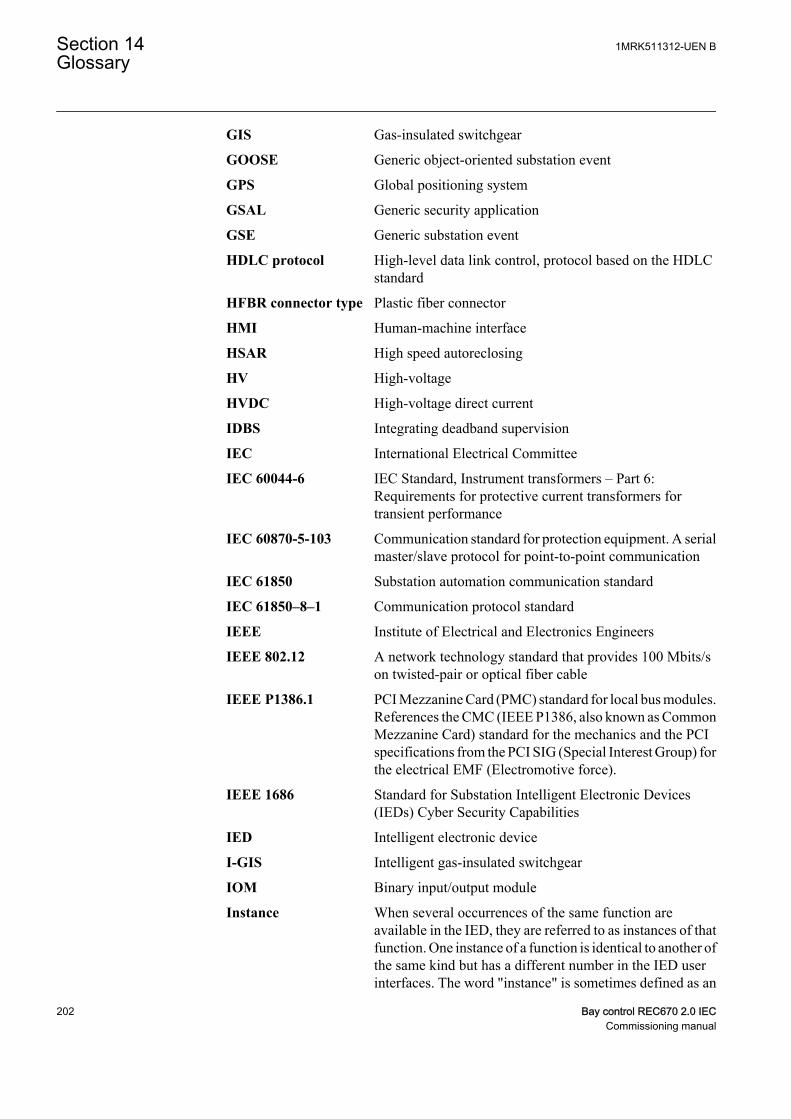
GIS Gas-insulated switchgear
GOOSE Generic object-oriented substation event
GPS Global positioning system
GSAL Generic security application
GSE Generic substation event
HDLC protocol High-level data link control, protocol based on the HDLCstandard
HFBR connector type Plastic fiber connector
HMI Human-machine interface
HSAR High speed autoreclosing
HV High-voltage
HVDC High-voltage direct current
IDBS Integrating deadband supervision
IEC International Electrical Committee
IEC 60044-6 IEC Standard, Instrument transformers – Part 6:Requirements for protective current transformers fortransient performance
IEC 60870-5-103 Communication standard for protection equipment. A serialmaster/slave protocol for point-to-point communication
IEC 61850 Substation automation communication standard
IEC 61850–8–1 Communication protocol standard
IEEE Institute of Electrical and Electronics Engineers
IEEE 802.12 A network technology standard that provides 100 Mbits/son twisted-pair or optical fiber cable
IEEE P1386.1 PCI Mezzanine Card (PMC) standard for local bus modules.References the CMC (IEEE P1386, also known as CommonMezzanine Card) standard for the mechanics and the PCIspecifications from the PCI SIG (Special Interest Group) forthe electrical EMF (Electromotive force).
IEEE 1686 Standard for Substation Intelligent Electronic Devices(IEDs) Cyber Security Capabilities
IED Intelligent electronic device
I-GIS Intelligent gas-insulated switchgear
IOM Binary input/output module
Instance When several occurrences of the same function areavailable in the IED, they are referred to as instances of thatfunction. One instance of a function is identical to another ofthe same kind but has a different number in the IED userinterfaces. The word "instance" is sometimes defined as an
Section 14 1MRK511312-UEN BGlossary
202 Bay control REC670 2.0 IECCommissioning manual
item of information that is representative of a type. In thesame way an instance of a function in the IED isrepresentative of a type of function.
IP 1. Internet protocol. The network layer for the TCP/IPprotocol suite widely used on Ethernet networks. IP is aconnectionless, best-effort packet-switching protocol. Itprovides packet routing, fragmentation and reassemblythrough the data link layer.2. Ingression protection, according to IEC 60529
IP 20 Ingression protection, according to IEC 60529, level 20
IP 40 Ingression protection, according to IEC 60529, level 40
IP 54 Ingression protection, according to IEC 60529, level 54
IRF Internal failure signal
IRIG-B: InterRange Instrumentation Group Time code format B,standard 200
ITU International Telecommunications Union
LAN Local area network
LIB 520 High-voltage software module
LCD Liquid crystal display
LDCM Line differential communication module
LDD Local detection device
LED Light-emitting diode
LNT LON network tool
LON Local operating network
MCB Miniature circuit breaker
MCM Mezzanine carrier module
MIM Milli-ampere module
MPM Main processing module
MVAL Value of measurement
MVB Multifunction vehicle bus. Standardized serial busoriginally developed for use in trains.
NCC National Control Centre
NOF Number of grid faults
NUM Numerical module
OCO cycle Open-close-open cycle
OCP Overcurrent protection
OEM Optical Ethernet module
1MRK511312-UEN B Section 14Glossary
Bay control REC670 2.0 IEC 203Commissioning manual
OLTC On-load tap changer
OTEV Disturbance data recording initiated by other event thanstart/pick-up
OV Overvoltage
Overreach A term used to describe how the relay behaves during a faultcondition. For example, a distance relay is overreachingwhen the impedance presented to it is smaller than theapparent impedance to the fault applied to the balance point,that is, the set reach. The relay “sees” the fault but perhapsit should not have seen it.
PCI Peripheral component interconnect, a local data bus
PCM Pulse code modulation
PCM600 Protection and control IED manager
PC-MIP Mezzanine card standard
PMC PCI Mezzanine card
POR Permissive overreach
POTT Permissive overreach transfer trip
Process bus Bus or LAN used at the process level, that is, in nearproximity to the measured and/or controlled components
PSM Power supply module
PST Parameter setting tool within PCM600
PT ratio Potential transformer or voltage transformer ratio
PUTT Permissive underreach transfer trip
RASC Synchrocheck relay, COMBIFLEX
RCA Relay characteristic angle
RISC Reduced instruction set computer
RMS value Root mean square value
RS422 A balanced serial interface for the transmission of digitaldata in point-to-point connections
RS485 Serial link according to EIA standard RS485
RTC Real-time clock
RTU Remote terminal unit
SA Substation Automation
SBO Select-before-operate
SC Switch or push button to close
SCL Short circuit location
SCS Station control system
Section 14 1MRK511312-UEN BGlossary
204 Bay control REC670 2.0 IECCommissioning manual
SCADA Supervision, control and data acquisition
SCT System configuration tool according to standard IEC 61850
SDU Service data unit
SLM Serial communication module.
SMA connector Subminiature version A, A threaded connector withconstant impedance.
SMT Signal matrix tool within PCM600
SMS Station monitoring system
SNTP Simple network time protocol – is used to synchronizecomputer clocks on local area networks. This reduces therequirement to have accurate hardware clocks in everyembedded system in a network. Each embedded node caninstead synchronize with a remote clock, providing therequired accuracy.
SOF Status of fault
SPA Strömberg Protection Acquisition (SPA), a serial master/slave protocol for point-to-point and ring communication.
SRY Switch for CB ready condition
ST Switch or push button to trip
Starpoint Neutral point of transformer or generator
SVC Static VAr compensation
TC Trip coil
TCS Trip circuit supervision
TCP Transmission control protocol. The most common transportlayer protocol used on Ethernet and the Internet.
TCP/IP Transmission control protocol over Internet Protocol. Thede facto standard Ethernet protocols incorporated into4.2BSD Unix. TCP/IP was developed by DARPA forInternet working and encompasses both network layer andtransport layer protocols. While TCP and IP specify twoprotocols at specific protocol layers, TCP/IP is often used torefer to the entire US Department of Defense protocol suitebased upon these, including Telnet, FTP, UDP and RDP.
TEF Time delayed earth-fault protection function
TLS Transport Layer Security
TM Transmit (disturbance data)
TNC connector Threaded Neill-Concelman, a threaded constant impedanceversion of a BNC connector
TP Trip (recorded fault)
1MRK511312-UEN B Section 14Glossary
Bay control REC670 2.0 IEC 205Commissioning manual
TPZ, TPY, TPX, TPS Current transformer class according to IEC
TRM Transformer Module. This module transforms currents andvoltages taken from the process into levels suitable forfurther signal processing.
TYP Type identification
UMT User management tool
Underreach A term used to describe how the relay behaves during a faultcondition. For example, a distance relay is underreachingwhen the impedance presented to it is greater than theapparent impedance to the fault applied to the balance point,that is, the set reach. The relay does not “see” the fault butperhaps it should have seen it. See also Overreach.
UTC Coordinated Universal Time. A coordinated time scale,maintained by the Bureau International des Poids etMesures (BIPM), which forms the basis of a coordinateddissemination of standard frequencies and time signals.UTC is derived from International Atomic Time (TAI) bythe addition of a whole number of "leap seconds" tosynchronize it with Universal Time 1 (UT1), thus allowingfor the eccentricity of the Earth's orbit, the rotational axis tilt(23.5 degrees), but still showing the Earth's irregularrotation, on which UT1 is based. The CoordinatedUniversal Time is expressed using a 24-hour clock, and usesthe Gregorian calendar. It is used for aeroplane and shipnavigation, where it is also sometimes known by themilitary name, "Zulu time." "Zulu" in the phonetic alphabetstands for "Z", which stands for longitude zero.
UV Undervoltage
WEI Weak end infeed logic
VT Voltage transformer
X.21 A digital signalling interface primarily used for telecomequipment
3IO Three times zero-sequence current.Often referred to as theresidual or the earth-fault current
3UO Three times the zero sequence voltage. Often referred to asthe residual voltage or the neutral point voltage
Section 14 1MRK511312-UEN BGlossary
206 Bay control REC670 2.0 IECCommissioning manual

207

Contact us
For more information please contact:
ABB ABSubstation Automation ProductsSE-721 59 Västerås, SwedenPhone +46 (0) 21 32 50 00
www.abb.com/substationautomation
Note:We reserve the right to make technical changes or modifythe contents of this document without prior notice. ABB ABdoes not accept any responsibility whatsoever for potentialerrors or possible lack of information in this document.We reserve all rights in this document and in the subjectmatter and illustrations contained herein. Any reproduction,disclosure to third parties or utilization of its contents – inwhole or in part – is forbidden without prior written consent ofABB AB.
© Copyright 2014 ABB.
All rights reserved.
Scan this QR code to visit our website
1MR
K51
1312
-UE
N