Embed Size (px)
Citation preview

BA
TT
ER
Y
PO
WE
RE
D
MO
BI
LE
S
TA
IR
C
LI
MB
ER
BATTERY POWERED
Mobile Stair Climber
OwnersManual
Models CoveredMK7, MK8, MK9,
MK10, SM10A,SM11, SM11 SES,
SM12 SES
Established 1982
Stairmatic
Manual

S T A I R M A T I C M O B I L E S T A I R C L I M B E R O P E R A T I N G M A N U A L
Page 2
Contents
This symbol occurs where important points are being highlighted.Not observing these points may have safety implications.
Page
1 Declaration of Conformity ...................................................................... 3
2 Stair and Step Assessment ................................................................... 4
3 Operating Instructions ............................................................................ 5
4 Battery Charging Instructions ............................................................... 15
5 Schematic ................................................................................................... 17
6 Control Panels ........................................................................................... 18
7 Stair Tread Requirements........................................................................ 19
8 Specifications ............................................................................................ 20
9 Engineering and Service ........................................................................ 21
9.1 Fault Diagnosis ......................................................................................... 22
9.3 Servicing Schedules ................................................................................ 23
9.4 Service Procedures .................................................................................. 24
9.5 Spare Parts ................................................................................................ 32
10 Warranty ..................................................................................................... 33
11 Disposal ..................................................................................................... 33
!

S T A I R M A T I C M O B I L E S T A I R C L I M B E R O P E R A T I N G M A N U A L
Page 3
Flansham Business CentreHoe Lane, Flansham,Bognor Regis, West Sussex,England. PO22 8NJ
Telephone: 01243 586692 Fax: 01243 586312Website www.baronmead.com Email [email protected]
Baronmead International Ltd - The Manufacturer
DECLARATION OF CONFORMITYKONFORMITÄTS-ERKLÄRUNGDÉCLARATION DE CONFORMITÉEG-VERKLARING VAN OVEREENSTEMMINGDICHIARAZIONE DI CONFORMITA
_______________________________________________________________
We declare that the construction of the product(s)Hermit erklären wir, daß die Bauart der(s) produkte(s)Nous declarons quë le(s) produit(s)Hierbij verklaren wij, dat de bouwwijze van de/het product(en)Dichiariamo che il(i) prodotto(i)
STAIRMATIC STAIR CLIMBERComply with the following European Directivese conforme alle seguenti Direttive Europee
Directive 89/336 “Electromagnetic Compatibility” as modified by Directive 92/31/CEDirettiva 89/336/CEE “Compatibilita Elettromagnetica” come modificata dalla direttiva 92/31/CEE
Directive 93/42 “Medical Devices” (Category 1)Direttiva 93/42 “Dispositivi Medici” CCategoria 1)
Directive 98/37 “Machinery” as modified by Directive 98/79/CEDirettiva 98/37 “Macchine” come modificata dalla Direttiva 98/79/CEE
at Bognor Regis: ............................................. .............................................Date/Datum Signature / Handtekening
Graham White Managing Director
Legal Representative
January 2009
Established 1982
S T A I R M A T I C M O B I L E S T A I R C L I M B E R O P E R A T I N G M A N U A L
Page 4
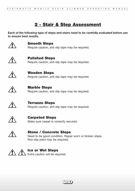
2 - Stair & Step Assessment
Each of the following type of steps and stairs need to be carefully evaluated before useto ensure best results.
Smooth Steps Require caution, anti slip tape may be required.
Polished StepsRequire caution, anti slip tape may be required.
Wooden StepsRequire caution, anti slip tape may be required.
Marble StepsRequire caution, anti slip tape may be required.
Terrazzo StepsRequire caution, anti slip tape may be required.
Carpeted StepsMake sure carpet is correctly secured.
Stone / Concrete StepsNeed to be good condition. Repair worn or broken steps. Non-slip paint may be required.
Ice or Wet StepsExtra caution will be required.
!
!
!
!
!
!
!
! !

S T A I R M A T I C M O B I L E S T A I R C L I M B E R O P E R A T I N G M A N U A L
Page 5
3 - Stairmatic - Operating Instructions
You must be a physically and mentally capable adult to operate the Stairmatic and haveachieved a competent operating level before you use the Stairmatic to carry a passenger,where possible BARONMEAD training is advised.
Please read these instructions carefully and ensure you are fully familiar with the Stairmaticbefore use. (If you have a training dvd, use with these notes).
3.1 General
The operating technique is to lean the Stairmaticback and let the machine do the lifting.
First familiarise yourself with the machine bystanding on a flat surface and tilting the machineback towards you. At a point about 20 degreesfrom the vertical the machine is “in balance” withlittle weight being transferred to your arms orwrists. This is the point of balance referred to inthese instructions.
Practice sessions should be held on a regularbasis. Monthly practice is advised as a minimum.
Check that the stair surfaces are secure and freefrom obstructions. Ensure that the nosings aresecure. Some nosings are very wide and theStairmatic may feel like it has arrived at the stepedge when the main wheels reach the back edgeof the nosing. (The Step Edge Sensor (referred to from here as SES) feature (where fitted) willnot allow the machine to drive down until the brakes are correctly locating the machine at thestep edge.)
Before using the Stairmatic with a passenger for the first time it is recommend that theoperator practices with the machine empty until the operating principals are understoodand confidence is gained in its use.
!
!
1

S T A I R M A T I C M O B I L E S T A I R C L I M B E R O P E R A T I N G M A N U A L
Page 6
3.2 Preparation
After a number of practice runs up and down the stairs with the Stairmatic empty, try thesame process with an able bodied volunteer of a similar weight to the operator. You will findthat the most comfortable tilt position will vary slightly due to the additional weight. First, getthe feel for the point of balance on level ground before approaching the first step. Keeping afirm hold on the handle, proceed as you have previously practiced until a comfortabletechnique is achieved.
In the early stages of learning with awkward staircases, or with nervous or heavy passengers,it is recommended that two people use the Stairmatic. The second member of the teamstands below the machine ensuring the machine is in the correct position on the step andreassuring the passenger. Repeat this procedure until you are confident
If a trained operative is available have a ride yourself so that you can appreciate the ride fromthe passengers’ point of view. Remember your confidence will transfer itself to the rider.
Before transferring the passenger, prepare the Stairmatic:
n Examine the machine before use; check the clamps are correctly adjusted (Section 9.4.10),check brake pad wear is within acceptable limits (Section 9.4.11), check chains are straightand undamaged.
n Establish that the passenger to be carried is within the capacity of the machine. (Refer tosection 3.11). It is recommended that only experienced and competent users attempt to carrypassengers significantly exceeding their own weight.
n Switch the machine on (and check for a steady status LED, SM10a - 12 see schematic)
n Lift up the arm rest where needed.
n Undo the seat harness.
n If necessary, raise the footrest.
n Transfer the passenger to the Stairmatic.
n Once the passenger is seated comfortably, fold down the arm rest.
n Secure the harness and adjust to a suitable tension.
n Release the foot rest lever, lower the foot rest and tilt the Stairmatic back to lock the footrest in place.
!

S T A I R M A T I C M O B I L E S T A I R C L I M B E R O P E R A T I N G M A N U A L
Page 7
3.3 On the Level
On a level surface use the Stairmatic upright. Hold the machinewith one hand on the top handle and the other on the lowerhandle, it can then be manouvered on the level. If the surface isuneven or very soft it may be easier to first tilt the Stairmatic at acomfortable angle before moving. Sometimes it is easier to pullthe Stairmatic backwards rather than push forwards.
3.4 Going up Stairs
Approaching the stairs to go up:
n Pull the Stairmatic backwards to the first step.
n Make sure that the lift wheels, which are attached to the chainsat the rear of the chair, are high enough to clear the front of the step,if not, lean back and drive the machine “UP” until the lift arms liftand lower, bringing the next pair of arms to the top (See diagram 3).
n Pull the machine back so that both the stair glides are restingagainst the nose of the step (See diagram 4).
The “Up” and “Down” controls are immobilised in theupright position. This is to remind you that the Stairmatic is to beused in the correct ‘tilted back’ position.
To tilt the Stairmatic back to the point of balance and at acomfortable angle you will need be up a few steps. Usually this isabout three steps. See diagrams 1 & 4)
The machine is now ready to climb the stairs.
n Hold the machine firmly with the machine leant backslightly beyond the balance position and press and hold the “UP” button. Press down onthe handle at the start of the lift cycle.
n The lift wheels raise the Stairmatic on to the next step whilst the operator maintains thecorrect balance position.
n As the machine climbs each step it is necessary for you to move up with the machine.
When the Stairmatic lands on each step draw the machine back against the nose of the nextstep ready to climb again. Be sure to maintain the correct angle of tilt.
2
4
3
!

S T A I R M A T I C M O B I L E S T A I R C L I M B E R O P E R A T I N G M A N U A L
Page 8
n On the top three steps, maintain the angle of the machine until the top step is reachedwhere the top and lower handles can be used to move the machine fully away from the topstep before returning it to the upright position.
The technique will soon be developed into a smooth and continuous motion.
When first driven “UP”, the machine may try to return to the vertical position.To counteract this as the machine starts to lift, downward pressure should be applied to the handle.This effect can be reduced by increasing the angle of tilt until balance is reached while lifting.
Always maintain a firm hold on the handle.
When you reach the top of the stairs pull the Stairmatic fully away from the edge usingthe lower handle for control, then ease the machine into an upright position.
3.5 To Go Down Stairs
First, before approaching the edge of the stairs, tilt the Stairmatic back slightlybeyond the point of balance - the same angle used when ascending. Practice this to ensureyou are not carrying too much weight on your arms and wrists.Use the top and lower handles (as in diagram 5).
n Push the Stairmatic slowly forward until you feel it stop atthe stair edge (See diagram 6). The braking system actsautomatically on the edge of each step. (Once the brakeshave reached the edge of the step the SES (where fitted) will
activate and allow themachine to be driven down tothe next step).
n Maintaining the correctangle of tilt, place both yourhands on the top handle, press the “DOWN” button and themachine will lift and lower to the next step, stay close to themachine so, as it lands it rests against your body (as themachine lands the speed will ramp down to stop until the nextstep edge is sensed, SES machines only).
5
6
!
!
!
!

S T A I R M A T I C M O B I L E S T A I R C L I M B E R O P E R A T I N G M A N U A L
Page 9
n Push the machine forward to the edge of the next step, again the brakes lock (and the SESwill allow the machine to be driven down).
n Press “DOWN” and again the Stairmatic will lift and lower.
Practice this to obtain a smooth and continuous action down the stairs. (Once the bottom ofthe stairs is reached the SES will stop the machine from driving until the next downward stepedge is sensed.)
3.6 Practice
After initial training, practice sessions should be held on a regular basis. Monthly practice isadvised to ensure continued familiarity. If the operator has not used the machine recently, startempty again to familiarise yourself before attempting to carry a passenger.

S T A I R M A T I C M O B I L E S T A I R C L I M B E R O P E R A T I N G M A N U A L
Page 10
There may be occasions when the Stairmatic is required to negotiate unusual stairs, seesection 7 for more details on dimensions required.
3.7 Fan shaped stairs
To check whether the Stairmatic CAN be used first try it without a passenger. Tooperate the Stairmatic on a fan shape the same principals of operation apply. It will beobvious that the machine has to be turned on each step of the fan. On the way up, makesure that both the stair glides are pulled back tight against the nose of each step (see diagram3). On the way down, (the SES will stop the machine from driving down unless) both brakesare (sensing) on each step edge.
If there is insufficient stair tread for the brakes to operate then the Stairmatic must notbe used. In order for the brakes to lock the Stairmatic normally needs a minimum tread depthof about 175mm (see stair tread requirement - Section 7). To get this dimension on a fan it isnecessary to keep some distance away from the centre of the fan, but care must be taken thatthe footrest does not make contact with the facing wall or stairway, or the handle with theadjacent wall.
3.8 Landings
To check whether the Stairmatic can be used first try it without a passenger. Tonegotiate a small landing with a right angle turn using the Stairmatic requires a slightlydifferent technique. Going up, as the machine reaches the top step onto the landing theoperative should stand to the side of the machine in the direction of travel, still maintainingthe correct angle of tilt. Place one hand on the lower handle and draw the Stairmatic backfrom the step and at the same time draw it round to approach the next flight of steps. Unlessyou are on a particularly wide staircase it is advisable to stay close to the inside of thestaircase to allow clearance on the turn.
Coming down the stairs to the landing is the reverse procedure. Stand to the side ofthe Stairmatic from the direction of travel, align the machine correctly on the top step of the nextflight of stairs. Both brakes must be locked on the edge of the top step before (the SES will allowthe machine to be) driven down. It is advisable to drive down one step, stop and keeping themachine in the balance position, move square behind the machine before continuing.
Note: Each stair has different obstructions, (Radiators, Windows, and Banisters). Eachstaircase needs evaluating to determine the Stairmatic’s suitability.
!
!
!
!
!

S T A I R M A T I C M O B I L E S T A I R C L I M B E R O P E R A T I N G M A N U A L
Page 11
3.9 Key Points
A) The operator must follow the manufacturer’s instructions to use theStairmatic safely.
B). The operator should wear suitable footwear and clothing when usingthe Stairmatic.
C). Do not allow the seat harness or loose clothing to become entangled in thelift chains.
D). Do not attempt to manoeuvre the machine from side to side while the chain liftwheels are in contact with the stairs as damage can occur to the lift mechanism.
E). Extra caution is required on wet, slippery and unsound surfaces, be extravigilant in these circumstances (See section 2).
F). In the event of a EMERGENCY on the stairs, where possible, return to thetop or bottom of the stairs. If this is not possible, drive the Stairmatic onto the chain lift wheels and lay on stairs in its EMERGENCY POSITION as shown in diagram 7, and seek assistance. Do not leave the rider unattended in the machine.
G). Make sure children, pets and other distractions are kept safely away whilethe machine is in use.
H) The operator should always stand behind the Stairmatic when in use on thestairs, unless dealing with a limited space staircase.
!
!
!
!
!
!
!
7
S T A I R M A T I C M O B I L E S T A I R C L I M B E R O P E R A T I N G M A N U A L
Page 12
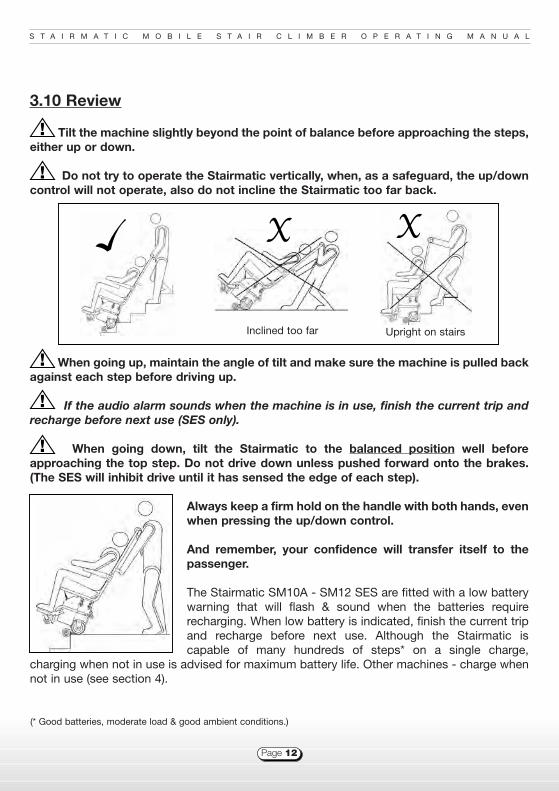
3.10 Review
Tilt the machine slightly beyond the point of balance before approaching the steps,either up or down.
Do not try to operate the Stairmatic vertically, when, as a safeguard, the up/downcontrol will not operate, also do not incline the Stairmatic too far back.
When going up, maintain the angle of tilt and make sure the machine is pulled backagainst each step before driving up.
If the audio alarm sounds when the machine is in use, finish the current trip andrecharge before next use (SES only).
When going down, tilt the Stairmatic to the balanced position well beforeapproaching the top step. Do not drive down unless pushed forward onto the brakes.(The SES will inhibit drive until it has sensed the edge of each step).
Always keep a firm hold on the handle with both hands, evenwhen pressing the up/down control.
And remember, your confidence will transfer itself to thepassenger.
The Stairmatic SM10A - SM12 SES are fitted with a low batterywarning that will flash & sound when the batteries requirerecharging. When low battery is indicated, finish the current tripand recharge before next use. Although the Stairmatic iscapable of many hundreds of steps* on a single charge,
charging when not in use is advised for maximum battery life. Other machines - charge whennot in use (see section 4).
!
!
!
!
!
Inclined too far Upright on stairs
(* Good batteries, moderate load & good ambient conditions.)

S T A I R M A T I C M O B I L E S T A I R C L I M B E R O P E R A T I N G M A N U A L
Page 13
3.11 Security Features
The Stairmatic SM10a - SM12 SES’s have a red Emergency Stop switch located on the tophandle. This in conjunction with the controller will stop the motor driving.
A key switch is fitted to the Stairmatic to prevent unauthorised use. The machine is “on” when the key is horizontal and the LED is illuminated (SM10a - SM12)
The maximum load on the Stairmatic SM10a - 12 is 130 Kgs. (20 stone), Mk7 - 10 is115Kg (18 stone).
If machine is obstructed or overloaded, an overload cut-out may activate. Once the cause ofthe overload has been removed, the cut-out can be re-engaged by pressing the “trip” switchon the control panel (see section 6).The SM10a - SM12 controller has an auto-resetting current limiter that may temporarily stopthe machine under overload conditions.
3.12 Transportation and Disassembly
Should you wish to transport the Stairmatic there are several ways of doing this.
n First, the chain lift wheels must be driven to the north-south (top-bottom) position out ofthe way to prevent them being damaged. The machine can now be transported laid on itsback or upright (where possible). Refer to you particular vehicle manual to secure for transit.
n Alternatively the Stairmatic can be separated into two parts. First, drive the chain lift wheelsto “north - south”, then unplug the seat control cable plug from the control panel of the baseunit, then undo the four seat clamps, two on each side, and lift off the seat. Refitting is thereverse of this procedure. Take care to ensure that the plug locates correctly in the socketduring reconnection and the seat clamps are correctly adjusted - refer to the section 9.4.10.

S T A I R M A T I C M O B I L E S T A I R C L I M B E R O P E R A T I N G M A N U A L
Page 14
3.13 Storage and Batteries
When the Stairmatic is not in use, store the machine in a dry, sheltered environment.
Switch the machine off, using the charger / lead supplied, connect it to the socket on the controlpanel, Switch on and observe that the red charger-on light is showing. When charging iscomplete, the green light shows (Refer to the charger instructions for your model - section 4).
Do not use chargers outside.
The Batteries are sealed units and require no maintenance other than regular charging. Donot use unapproved battery chargers as these may damage the batteries. It is bad practiceto let the batteries become heavily discharged, as this will shorten the battery life. If lowbatteries are indicated, switch off and recharge the machine as soon as possible.
SM10a - 12; The status indicator and battery alarm fitted to the Stairmatic SES’s showswhen the battery voltage drops below a set level. A slow flash and beep indicates this.Recharge the machine as soon as practically possible after low batteries are indicated.
As the batteries get old, the capacity will be reduced and it will be capable of less work. Thiswill correspond to a reduction of time before low batteries are indicated. If the batteries areslow after a full charge and the alarm sounds / status LED flashes soon after commencing usethis indicates very low battery capacity, the batteries have ended their useful life. If, whenascending, it becomes obvious that there is insufficient power - do not continue. Rest thebatteries for a short while to let them recover some capacity, then descend as normal. Putthe machine on charge immediately.
If a fast flash is observed, this indicates a system fault. The most common faults are batteryrelated and if the drive switch is activated when switched on. Switch the machine off and onagain to see if the fault clears.
!

S T A I R M A T I C M O B I L E S T A I R C L I M B E R O P E R A T I N G M A N U A L
Page 15
4 - Battery Charging Instruction
The Stairmatic Stair Climbers are powered by AGM sealed for life, lead acid type batteries. Toget maximum life from the batteries they should be kept in a high state of charge. Regulardeep discharges will dramatically reduce battery life. If the machine is not in use, chargebefore storing and again before next use (up to 3 months storage) or leave on chargepermanently so the machine is always ready for use, see recommended charging intervals foryour machine, this option reduces the risk of the damaging the batteries through insufficientcharging. Do not leave the machine switched on. If the low battery alarm sounds / status LEDflashes recharge as soon as possible (SM10a - SM12).
Instructions for use - Connect charger output / lead to Stairmatic Charger socket (Basecontrol panel) Connect charger to Mains supply then switch on. To get Maximum life fromthe battery, refer to recommended charging intervals.
n Stairmatic Mk7 & 8 - Two stage 12V Integrated charger, comprising of 1) boost charge,2) timed trickle charge and 3) off. Boost (Red) recovers the lost battery voltage, timed tricklecharge (Red & Yellow) stabilises battery cells for a timed period, and Off (Green).
n Stairmatic Mk9 - Two stage 12V Integrated charger, comprising of 1) boost charge, 2)constant voltage charge. Boost (Red) recovers the lost battery voltage, constant voltagecharge (Red & Green) stabilises battery cells, maintains battery charge over short-mediumtime periods.
n Stairmatic Mk10 - Two stage 12V Off board charger, comprising of 1) boost charge, 2)constant voltage charge. Boost (Red) recovers the lost battery voltage, constant voltagecharge (Green) stabilises battery cells, maintains battery charge over medium time periods.
n Stairmatic SM10a - SM12 - Three-stage 24V charger comprising of 1) constant currentboost charge, 2) proportional timed constant voltage stabilising charge and 3) float charge.Boost (Red & Yellow) recovers the lost battery voltage, constant voltage charge (Red &flashing Yellow) stabilises battery cells for a timed period proportional to first stage and Float(Red & Green) maintain batteries in a fully charged condition.

S T A I R M A T I C M O B I L E S T A I R C L I M B E R O P E R A T I N G M A N U A L
Page 16
Recommended charging intervals
* For heavy use (+6 journeys per day) charge when not being used. The machine can still beused if the charge cycle has not been completed but to maintain the battery condition itshould be charged to green regularly.
Chargers are for indoor use only, do not expose to rain or moisture.!
Standby Light Medium Heavy
Model <1 trip/day <1-6 trips/day >7 trips/day
Mk 7 & 8 Cycle Monthly Nightly When not in use When not in use
Mk 9 & 10 Cycle Monthly Nightly When not in use When not in use
SM 10a - 12 Leave on Nightly When not in use When not in use

S T A I R M A T I C M O B I L E S T A I R C L I M B E R O P E R A T I N G M A N U A L
Page 17
5 - Schematic
Features1. Serial Number2. Base Control Panel3. Seat Clamps4. Footrest Lever5. Brakes6. Footrest7. Harness8. Armrest9. Drive Buttons & Status LED10. Emergency Stop 11. Instruction Label
525-540mmArmrest widths(side to side)
1400mmTotal height
475mm - Base unit width
530mm - Floor to seat
2
1
4
6
5
9
10
11
8
7
3

S T A I R M A T I C M O B I L E S T A I R C L I M B E R O P E R A T I N G M A N U A L
Page 18
6 - Control Panels
Control Panel Items
LEGEND ItemMachine A B C D E F
Seat Connector
Mk 7 & 8 Mains in; IEC R/Y/G charger Trip 25A Key Switch 3 pin DIN plug
230V ac lights Typical
Mk 9 Mains in; IEC R/G charger Trip 25A Key Switch 3 pin XLR plug
230V ac light Typical
Mk 10 Charger in; 12V Battery check Trip 25A Key Switch 3 pin XLR plug
4 pin XLR lights Typical
SM10a Charger in; 24V Status LED Trip 15A Key Switch Controller fuse Qikmate 9 way
3 pin XLR Typical 4A connector
SM11 Charger in; 24V Status LED Trip 15A Key Switch Controller fuse Qikmate 9 way
3 pin XLR Typical 4A connector
SM11 SES Charger in; 24V Status LED Trip 15A Key Switch Qikmate 9 way
3 pin XLR Typical connector
SM12 SES Charger in; 24V Status LED Trip 15A Key Switch Qikmate 9 way
3 pin XLR Typical connector
Mk 7 / 8 Mk 9
SM10a / 11
B D C FADCFAB
Mk 10
A B D C F A B C D E F
SM11 / 12 SES
A C D B F

S T A I R M A T I C M O B I L E S T A I R C L I M B E R O P E R A T I N G M A N U A L
Page 19
7 - Stair Tread Requirement
*These dimensions are the minimum steprequired when using the machine at thecorrect angle. For training purposes deepersteps would be advisable until correct use ofthe machine is achieved. Please note thattread depth is measured from nose to nose ofthe step NOT the platform itself. In allcircumstances involving steps new to themachine, try the machine empty beforeattempting to use with a passenger.
7.1 Minimum Tread Required
1) Square Landing 2) Straight Stairs 3) 3 Step Fan 4) Spiral
7.2 Other Stair Requirements
1) The likely* minimum landing area is 800mm. 2) The minimum stair width for straight stairsis 600mm. 3&4) The likely* minimum stair width on 3 step fans and spiral stairs is 950mm
* As each staircase is different exact figures are not possible, but the chance of success decreases below these figuresand increases above them.
TREAD
RISE DEADSPACE
Stair Rise Tread Required*mm Stairmatic70 150 80 150 90 150
100 150 110 154 120 158 130 162 140 166 150 171 160 175 170 179 180 183 190 187 200 191 210 195 220 199 230 204 240 208 250 212 260 216 270 220 280 Not Suitable

S T A I R M A T I C M O B I L E S T A I R C L I M B E R O P E R A T I N G M A N U A L
Page 20
8 - Specifications
*Range will be influenced by battery condition and charge, load on machine and ambientconditions. This figure is for reference only, based on new batteries, 50% use (time), 75Kgload, 20 deg ambient condition. At approximately 60% of range, low battery flash and alarmwill activate. The battery life will be reduced (or batteries may be damaged) if the machine isdriven until this figure is achieved especially if the machine is left partially discharged over aperiod. To get maximum battery life, recharge after each use. When low battery alarmactivates, finish the current trip and recharge as soon as practical.
Dimensions Mk 7 - 10 SM10a - 12
Machine weight Kg 56 46
Batteries Ah 12V - 24/26 Ah 2* 12V - 12 Ah
Maximum passenger weight Kg (St / lb) 115 (18 / 255) 130 (20 / 280)
Dimensions (upright) W*D*H mm 525*825*1400 525*825*1400
Dimensions (20o from vertical) W*D*H mm 525*1200*1245 525*1200*1245
Armrest Folding Folding
Footrest Folding Folding
Performance
Speed Steps / minute 15
Range* ( 75Kg load ) Steps Up to 1000

S T A I R M A T I C M O B I L E S T A I R C L I M B E R O P E R A T I N G M A N U A L
Page 21
9 - Engineering and Service
Contents
9.1 General Fault Diagnosis 189.2 Charger Fault Diagnosis 199.3 Service Schedules 199.4 Servicing Procedures9.4.1 Battery Replacement 209.4.2 Partial Removal of the Controller panel 209.4.3 Complete Removal of the Controller Panel 219.4.4 Installing a New Controller 219.4.5 Adjusting the Chains 219.4.6 Replacing the Chains 229.4.7 Motor Removal 229.4.8 Bottom Cog Replacement 239.4.9 Wheel and Brake Assembly 239.4.10 Adjusting Seat Clamps 249.4.11 Brake Shoe Replacement 249.4.12 Footrest - Removal and Replacement 249.4.13 Seat Wiring Check 259.4.14 Seat Pad - Removal and Replacement 26

S T A I R M A T I C M O B I L E S T A I R C L I M B E R O P E R A T I N G M A N U A L
Page 22
9.1 General Fault Diagnosis

S T A I R M A T I C M O B I L E S T A I R C L I M B E R O P E R A T I N G M A N U A L
Page 23
9.2 Charger Fault Diagnosis
The manufacturer recommends six monthly scheduled services of the Stairmatic by anapproved service operative in compliance with LOLER lifting and handling regulations, anexcerpt of which is shown below. Failure to follow these procedures may compromise thecorrect operation of the machine.
LOLER excerpt:107 The 6-monthly period between thorough examinations specified in reg.9(3)(a)(i) applies toall lifting accessories, whether or not they are used for lifting persons. The regulation alsoapplies to all other lifting equipment used for lifting persons. Such machinery, eg a crane orFLT, even if intended to be used only occasionally for lifting persons, should be examined inaccordance with reg.9(3)(a)(i) unless the employer arranges to have the equipment examinedin accordance with a scheme of examination.This section can be found at the following HSE site:http://www.hse.gov.uk/lau/lacs/90-4.htm#para74
Stairmatic Serial NumberTo assist with servicing and ordering parts please record your machines serial number below.This can be found on the right hand side of the machines base section. See section 5.
9.3 Servicing Schedules
Fault Reason ActionNo Red Light 1. No mains in l Check mains supply.
2. LED fault l Check output of charger
3. Charger fault l Replace charger
No Yellow / Green Light
1. Not charging l Check connections to machine
l Check condition of cables
l Charger faulty
2. Battery l Battery not taking charge
Baronmead Service: Tel: 01243 586 692 email: [email protected] fax: 01243 586 312
Model Key #
Serial Number
S T A I R M A T I C M O B I L E S T A I R C L I M B E R O P E R A T I N G M A N U A L
Page 24
9.4 Servicing Procedures
9.4.1 Battery Replacement:
Care is required when handling batteries. Risk of shock.Isolate mains before removing covers.
a). Switch off the charger and machine, disconnect the charger.b). Remove the two securing screws for the battery cover, locatedunder the legs to the side of the machine.c). Pull the top lip of the battery cover outward and upward.d). Remove the battery securings.e). Draw the batteries forward partially onto the footrest.f). Disconnect the wires.g). Reverse the procedure to install new batteries.
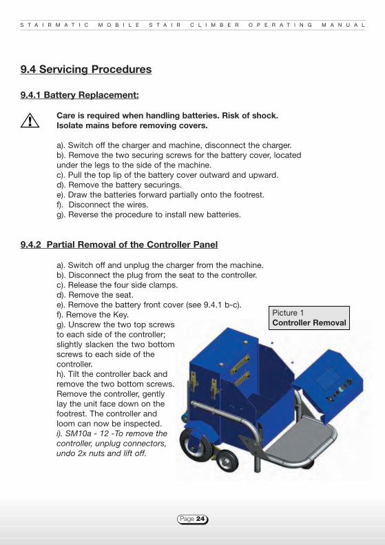
9.4.2 Partial Removal of the Controller Panel
a). Switch off and unplug the charger from the machine.b). Disconnect the plug from the seat to the controller.c). Release the four side clamps.d). Remove the seat.e). Remove the battery front cover (see 9.4.1 b-c).f). Remove the Key.g). Unscrew the two top screwsto each side of the controller; slightly slacken the two bottomscrews to each side of the controller.h). Tilt the controller back and remove the two bottom screws.Remove the controller, gently lay the unit face down on the footrest. The controller and loom can now be inspected. i). SM10a - 12 -To remove the controller, unplug connectors, undo 2x nuts and lift off.
Picture 1Controller Removal
!

S T A I R M A T I C M O B I L E S T A I R C L I M B E R O P E R A T I N G M A N U A L
Page 25
9.4.3 Complete Removal of the Controller Panel
a). Follow 9.4.2 a-h.b). Disconnect the motor cables at the controller.c). Disconnect the battery cables at the batteries.d). Disconnect the Tilt switch wires from the loom.e). Separate the wires from the loom and remove the control panel.f). To remove the controller, unplug connectors, undo 2x nuts and lift off.
9.4.4 Installing a New Controller
a). Reverse the steps in Section 9.4.2 i-a.b). Ensure all the connections are tight.
9.4.5 Adjusting the Chains
a). Drive the machine until the chain lift arms areabout half way between sprockets.b). Unplug the Seat connector, undo 4x clampsand remove the seat.c). From the rear of the machine, slacken the 4socket bolts holding the gearbox by 1/2 to 3/4 ofa turn. (a 6mm hex extension ball drive may berequired.)d). Adjust the chain tension with the two adjustingbolts on top of the base unit until all freemovement is taken out of the chains. Do not overtighten.e). Torque the 4 Socket bolts holding the gearboxto 15Nm.f). Tighten the chain tension bolts on top of thebase unit until slight resistance is felt.
Correctly tensioned chains will have no play inthem, but will not be under tension. To checkchain tension, drive the machine until the lift armsare about half way between the top and bottomsprockets and pull the chains outward from theback of the machine. 5mm movement should bepossible with little effort.
Picture 2Clamps & Chains

S T A I R M A T I C M O B I L E S T A I R C L I M B E R O P E R A T I N G M A N U A L
Page 26
9.4.6 Replacing the Chains
a). Drive the machine until the chain link is accessible on the top sprocket.b). Follow 9.4.5 b & c .c). Reduce the chain tension, undoing the adjusting bolts on top of the base unit until thechains are slack.d). Remove the chain links.e). Remove the chains.f). Fit the new chains, ensuring that the lift arms are horizontally aligned with each other. (Thisis most easily achieved by refitting the chains with the links on the top (drive) sprocket.) Fit thenew chain links and clips.g). Re-tension as in 9.4.5.
9.4.7 Motor Removal
a). Remove the chains, 9.4.6.a-e.b). Partially remove the Controller,9.4.2. & separate the motor cablesfrom the loom.c). Undo the stair glide screws, removethe stair glides and back cover.d). Remove the gearbox bolts andcaptive nuts (in controller section ofbase).e). Remove the motor, withdrawing themotor leads.
Reassemble in reverse order, fit a newcable tie to back plate and feed cablethrough before offering up motor.Adjust the chains to correct tension(see 9.4.5).
Picture 3Motor Removal
S T A I R M A T I C M O B I L E S T A I R C L I M B E R O P E R A T I N G M A N U A L
Page 27
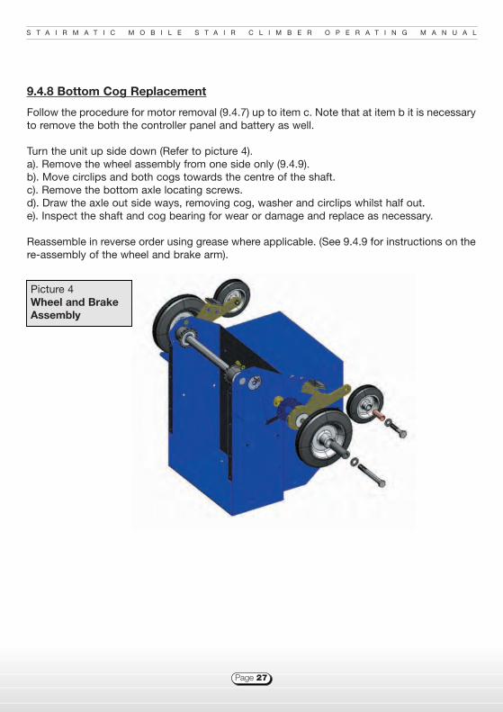
9.4.8 Bottom Cog Replacement
Follow the procedure for motor removal (9.4.7) up to item c. Note that at item b it is necessaryto remove the both the controller panel and battery as well.
Turn the unit up side down (Refer to picture 4).a). Remove the wheel assembly from one side only (9.4.9).b). Move circlips and both cogs towards the centre of the shaft.c). Remove the bottom axle locating screws.d). Draw the axle out side ways, removing cog, washer and circlips whilst half out.e). Inspect the shaft and cog bearing for wear or damage and replace as necessary.
Reassemble in reverse order using grease where applicable. (See 9.4.9 for instructions on there-assembly of the wheel and brake arm).
Picture 4Wheel and BrakeAssembly
S T A I R M A T I C M O B I L E S T A I R C L I M B E R O P E R A T I N G M A N U A L
Page 28
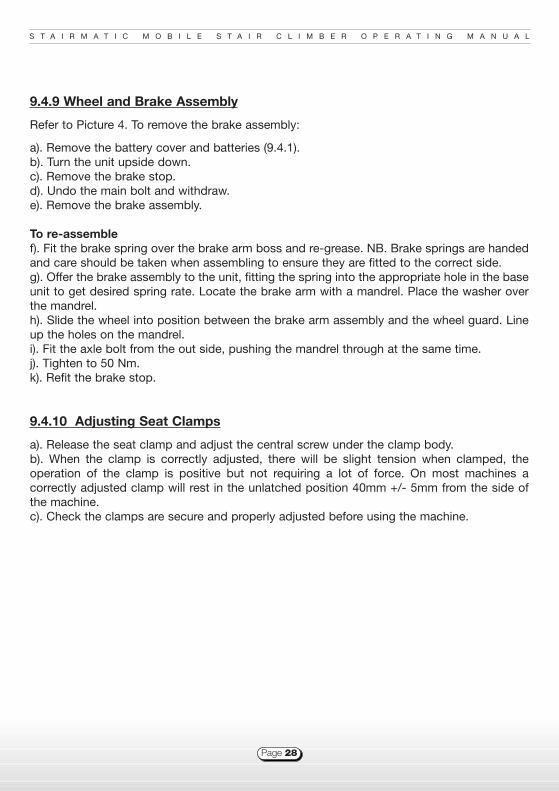
9.4.9 Wheel and Brake Assembly
Refer to Picture 4. To remove the brake assembly:
a). Remove the battery cover and batteries (9.4.1).b). Turn the unit upside down.c). Remove the brake stop.d). Undo the main bolt and withdraw.e). Remove the brake assembly.
To re-assemblef). Fit the brake spring over the brake arm boss and re-grease. NB. Brake springs are handedand care should be taken when assembling to ensure they are fitted to the correct side.g). Offer the brake assembly to the unit, fitting the spring into the appropriate hole in the baseunit to get desired spring rate. Locate the brake arm with a mandrel. Place the washer overthe mandrel.h). Slide the wheel into position between the brake arm assembly and the wheel guard. Lineup the holes on the mandrel.i). Fit the axle bolt from the out side, pushing the mandrel through at the same time.j). Tighten to 50 Nm.k). Refit the brake stop.
9.4.10 Adjusting Seat Clamps
a). Release the seat clamp and adjust the central screw under the clamp body.b). When the clamp is correctly adjusted, there will be slight tension when clamped, theoperation of the clamp is positive but not requiring a lot of force. On most machines acorrectly adjusted clamp will rest in the unlatched position 40mm +/- 5mm from the side ofthe machine.c). Check the clamps are secure and properly adjusted before using the machine.

S T A I R M A T I C M O B I L E S T A I R C L I M B E R O P E R A T I N G M A N U A L
Page 29
9.4.11 Brake Shoe Replacement
Replace brake shoes when the dimpleshave worn off the pad (see picture 5).a). Brake shoes are handed, please notefitment of shoe before removing. Tosave confusion it is easier to change oneshoe at a time. b). Remove the two socket screwsholding the old brake shoe.c). Fit the new shoe and refit the screws.
9.4.12 Footrest Removaland Replacement
To replace footrest wood
a). Undo 3 bolts holding the wood to theframe.b). Undo 4 bolts holding the castorwheel to the wood.c). Fit Castor wheel to new wood,securing with thread locker (Loctite 243or equivalent).d). Fit wood to frame, using threadlocker.e). Fit new footrest rubber.
Picture 5Brake Pad
Picture 6Footrest
S T A I R M A T I C M O B I L E S T A I R C L I M B E R O P E R A T I N G M A N U A L
Page 30
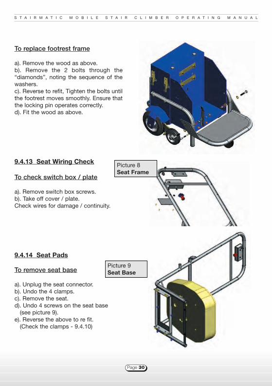
To replace footrest frame
a). Remove the wood as above.b). Remove the 2 bolts through the“diamonds”, noting the sequence of thewashers.c). Reverse to refit, Tighten the bolts untilthe footrest moves smoothly. Ensure thatthe locking pin operates correctly. d). Fit the wood as above.
9.4.13 Seat Wiring Check
To check switch box / plate
a). Remove switch box screws.b). Take off cover / plate.Check wires for damage / continuity.
9.4.14 Seat Pads
To remove seat base
a). Unplug the seat connector.b). Undo the 4 clamps.c). Remove the seat.d). Undo 4 screws on the seat base
(see picture 9).e). Reverse the above to re fit.
(Check the clamps - 9.4.10)
Picture 9Seat Base
Picture 8Seat Frame

S T A I R M A T I C M O B I L E S T A I R C L I M B E R O P E R A T I N G M A N U A L
Page 31
To remove the armrests
Mk 7 - SM12 sided
Undo two socket screws and remove.a). Arm rests are sided. Ensurereplacements are on the correct sidebefore fitting.
SM12 commonb). Remove socket screw holdingcover on armrest.c). Remove two socket screws holdingarmrest to frame.d). Assemble in reverse order, takingcare to align cover correctly.
To remove seat back
Follow a). to c). above.Remove the harness.Lay the seat on its back.Remove screws and washers.Lift off seat back.Ensure the inserts are correctlyinstalled in the seat backsleeves, screw seat onto frame.Re fit seat to base. (Check theclamps - 9.4.10)Re fit the harness.
Picture 10Seat Back
Picture 11Arm Rest

S T A I R M A T I C M O B I L E S T A I R C L I M B E R O P E R A T I N G M A N U A L
Page 32
9.5 Spare Parts

S T A I R M A T I C M O B I L E S T A I R C L I M B E R O P E R A T I N G M A N U A L
Page 33
10 - Warranty
The STAIRMATIC mobile stairclimber is guaranteed against material and workmanship defectsfor 12 months from date of first purchase, when used as instructed in this manual. Thewarrantee is only for the original purchaser of the equipment and is not transferable to thirdparties even within first year from purchase.Exceptions are made for fair wear and tear, misuse, and neglect. Accidental damage throughwater, fire, vandalism or other environmental factors are not covered. Maintenance and repairs must be carried out by an approved agent. Alterations ormodifications to the machine by anyone other than an approved agent will invalidate anywarranty. This does not affect your statutory rights.Baronmead International Limited reserves the right to change specifications without priornotice.
11 - Disposal
Please dispose of your Stairmatic in accordance with the regulations of your country. A significant percentage of your machine can be recycled:
n Batteries - please recycle at your local recycling centre or other relevant facility.n Electronic and electrical parts - please recycle at your local recycling centre or
other relevant facility.n Metal parts - please recycle at your local recycling centre or other relevant facility.
Other parts: please dispose of responsibly.
24

Flansham Business Centre,Hoe Lane, Flansham,
Bognor Regis,West Sussex,
England PO22 8NJ
Tel: 01243 586692 Fax: 01243 586312
Email: [email protected] Website: www.baronmead.comParts: [email protected]
(c) Baronmead International Limited - January 09
Established 1982
u Up to 1000 steps on full charge (depending on the passengers weight & the climate conditions)
u Standard speed 15 steps p/minute (Electronic system to control the Stairmatic operation &
automatically govern speed)
u Maintenance free (2x12v/12a) battery pack u Motor - 24v DC u Padded seat for extra comfort
u Supplied with arm rests and full harness u Compact off board charger
u Emergency stop button feature u Removable seat for easy transportation
u Made in England u C
u Height: 1400mm
u Width: 525mm
u Depth: 800mm
u Weight: 46kg
u Max load: 130kg / 20 Stone
u Max step height: 270mm