Embed Size (px)
Citation preview
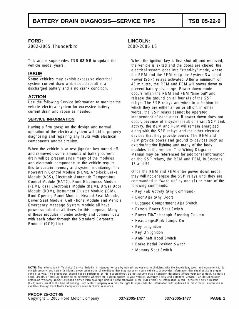
BATTERY DRAIN DIAGNOSIS—SERVICE TIPS TSB 05-22-9
FORD: LINCOLN:2002-2005 Thunderbird 2000-2006 LS
This article supersedes TSB 02-9-5 to update the When the ignition key is first shut off and removed,vehicle model years. the vehicle is exited and the doors are closed, the
electrical system goes into “stand-by” mode, whereISSUE the REM and the FEM keep the System SwitchedSome vehicles may exhibit excessive electrical Power (SSP) relays activated. After a minimum ofsystem current draw which could result in a 45 minutes, the REM and FEM will power down todischarged battery and a no crank condition. prevent battery discharge. Power down mode
occurs when the REM and FEM “time out” andACTION release the ground on all four (4) of the SSPUse the following Service Information to monitor the relays. The SSP relays are wired in a fashion invehicle electrical system for excessive battery which they are either all on or all off. In othercurrent drain and repair as needed. words, the SSP relays cannot be operated
independent of each other. If power down does notSERVICE INFORMATION
occur, because of a system fault or errant SCP Linkactivity, the REM and FEM will remain energizedHaving a firm grasp on the design and normalalong with the SSP relays and the other electricaloperation of the electrical system will aid in properlydevices that they provide power. The REM anddiagnosing and repairing any faults with electricalFEM provide power and ground to devices such ascomponents and/or circuitry.exterior/interior lighting and many of the body
When the vehicle is at rest (ignition key turned off modules in the vehicle. The Wiring Diagramsand removed), some amounts of battery current Manual may be referenced for additional informationdrain will be present since many of the modules on the SSP relays, the REM and FEM, in Sectionsand electronic components in the vehicle require 13 and 59.this to sustain memory and system monitoring. The
Once the REM and FEM enter power down modePowertrain Control Module (PCM), Anti-lock Brakethey will not energize the SSP relays until they areModule (ABS), Electronic Automatic Temperaturecommanded to “wake up” by one (1) or more of theControl Module (EATC), Front Electronics Modulefollowing commands:(FEM), Rear Electronics Module (REM), Driver Door
Module (DDM), Instrument Cluster Module (ICM), • Key Fob Activity (Any Command)Roof Opening Panel Module, Heated Seat Module, • Door Ajar (Any Door)Driver Seat Module, Cell Phone Module and Vehicle
• Luggage Compartment Ajar SwitchEmergency Message System Module all have• Drivers Power Seat Switchpower supplied at all times for this purpose. Many
of these modules monitor activity and communicate • Power Tilt/Telescopic Steering Columnwith each other through the Standard Corporate • Headlamps/Park Lamps OnProtocol (SCP) Link.
• Key In Ignition
• Key On Ignition
• Anti-Theft Hood Switch
• Brake Pedal Position Switch
• Memory Seat Switch
NOTE: The information in Technical Service Bulletins is intended for use by trained, professional technicians with the knowledge, tools, and equipment to dothe job properly and safely. It informs these technicians of conditions that may occur on some vehicles, or provides information that could assist in propervehicle service. The procedures should not be performed by “do-it-yourselfers”. Do not assume that a condition described affects your car or truck. Contact aFord, Lincoln, or Mercury dealership to determine whether the Bulletin applies to your vehicle. Warranty Policy and Extended Service Plan documentationdetermine Warranty and/or Extended Service Plan coverage unless stated otherwise in the TSB article.The information in this Technical Service Bulletin(TSB) was current at the time of printing. Ford Motor Company reserves the right to supercede this information with updates.The most recent information isavailable through Ford Motor Company’s on-line technical resources.
PROOF 25-OCT-05Copyright 2005 Ford Motor Company 037-2005-1477 037-2005-1477 PAGE 1
TSB 05-22-9 (Continued)
BATTERY DRAIN DIAGNOSIS 7. Drive the vehicle for at least 20 minutes over30 mph (48 km/h) to reach full engine operating
In order to properly diagnose a battery drain temperature and to turn on and activate vehicleconcern, the following procedures must be followed systems. Make sure all electrical componentsexactly as stated to produce the most accurate operate correctly like the horn, audio system,results. exterior/interior lighting, climate control, etc.
1. Ask the customer how long the vehicle must sit 8. Open the Left Front and Right Front door andbefore the battery goes dead. The vehicle is engage the latches so the vehicle interior canequipped with a 750 amp hour battery from the be accessed without disturbing the modulesfactory. If the battery is in proper working order, during this test.it will be able to withstand a 1 amp draw for 48hours without dropping the battery voltage 9. Lift the hood and compress the Anti-Theft Hoodbelow 10.5V. This information may help Switch with a clamp (if equipped).determine the amount of current drain present.
10. Open the trunk lid and unplug the electricalFor example, if a vehicle with a fully chargedconnection to the Luggage Compartment Lamp.battery will not start after an overnight soak, itLift and secure the trunk floor panel hook to thecan be assumed the battery current drain istrunk opening pinch weld. The battery and thegreater than 4 amps. This knowledge may aidRear Power Distribution Box are now easilyin diagnosis.accessible.
2. Check for any aftermarket equipment installedNOTEin the vehicle. Ask the customer if theyDO NOT ALLOW BATTERY POWER TO BEremoved any aftermarket equipment beforeDISCONNECTED FROM THE VEHICLE AT ANYbringing vehicle in for service. All aftermarketTIME DURING THIS TEST. IF BATTERYequipment remaining should be removed beforeDISCONNECT OCCURS, THE ENTIRE TESTproceeding with this test.MUST BE PERFORMED AGAIN STARTING AT
3. Ask the customer if any electrical component(s) STEP 5.is inoperative or malfunctioning. In many cases
11. Use a Multimeter (DVOM) with a MIN/MAXa draining battery concern can usually befeature to measure the battery current drain.traced back to a component that hasThe DVOM must be capable of reading DCexperienced operational trouble.milliamps (minimum 1mA) and have 10 amp -
4. Using an appropriate scan tool, check all fused capacity.available modules in the vehicle for both
12. Use the following procedure to measure currenton-demand and continuous memory diagnosticdrain.trouble codes (DTCs). Repair any on-demand
DTC’s before continuing with this article. a. Turn on the DVOM and select DC AMPS.Record any continuous memory DTCs whichmay aid in future diagnosis. b. Attach a large alligator clip on each side of
the Battery Saver/Anti-Theft Switch5. Check that the vehicle battery is properly Terminals.
charged and that the charging system isoperating correctly. Refer to Workshop Manual c. Connect the DVOM in series by securingSection 414-00. the leads to the alligator clips on the Battery
Saver/Anti-Theft terminals.6. Install a quick disconnect style Battery
Saver/Vehicle Anti-Theft Switch between the d. Loosen the knob on the Batterynegative battery post and cable, such as Saver/Anti-Theft Switch to break the contactLittlefuse Part Number ATD 100 BP or Moroso between the negative battery terminal andPart Number 74103. cable.
NOTEDO NOT USE A TEST LIGHT OR A VOLT METERAS A CHECK FOR EVIDENCE OF CURRENTFLOW. A TEST LIGHT WILL NOT ACCURATELYDETERMINE THE AMOUNT OF CURRENT FLOW.
PAGE 2 037-2005-1477 037-2005-1477 PROOF 25-OCT-05

TSB 05-22-9 (Continued)
13. Wake the electrical system up by depressing a. Lincoln LS - Fuses 4.01 through 4.18the lock or unlock button on the key fob.
b. Thunderbird - Fuses 4.17 through 4.41Observe the reading on the DVOM. The currentflow will “jump” momentarily then after 1-2 NOTEminutes settle to the level listed below (a). REMOVING AND REINSTALLING FUSES 2.20 (LSActual readings may vary slightly depending on AND THUNDERBIRD) AND 4.14 (LS ONLY),vehicle equipment, battery condition, ambient DURING THE FOLLOWING TESTS WILL PROMPTtemperature and DVOM: THE SYSTEM TO “WAKE UP”. THE CURRENT
DRAIN ON THE METER WILL JUMPa. .85 amps (850mA) or less (Stand By Mode)MOMENTARILY FOR 1-2 MINUTES THEN
b. .035 amps (35mA) or less after 45 minutes SLOWLY DECREASE TO PREVIOUSLYminimum (Power Down Mode) MEASURED LEVELS.
14. During Stand By Mode, current drain readings NOTEof 850mA or less indicate the vehicle is DO NOT REMOVE THE LARGE AMPERAGEperforming normally. However, the concern may CARTRIDGE FUSES OR ANY RELAYS FROMbe intermittent in nature. Set the MIN/MAX THE RPDB. BY DOING SO POWER WILL BEfeature on the DVOM and periodically check LOST TO MULTIPLE FUSES, RELAYS ANDthe meter for evidence of excessive current COMPONENTS ALL AT THE SAME TIME. THISdrain. The MIN/MAX feature will record the TEST IS ATTEMPTING TO LOCATE THEhighest measured current reading. BATTERY CURRENT DRAIN AS CLOSE TO THE
COMPONENT LEVEL AS POSSIBLE.15. An electrical system that is operating normally
will power down to 35mA or less after 45 NOTEminutes minimum. However, it may not be DO NOT REMOVE FUSES 4.23, 4.24, 4.27, 4.32necessary to wait for Power Down Mode to (LS) - 4.10, 4.15, 4.27, 4.28 (THUNDERBIRD) ORbegin diagnosing the source of excessive SSP RELAYS 1, 2, 3, 4 DURING STAND BYbattery current drain. For example: A current MODE. REMOVING THESE FUSES AND RELAYSdrain reading of 2.5 amps is observed during WILL LESSEN BATTERY CURRENT DRAINStand By Mode. Knowing a normal system will BECAUSE YOU HAVE REMOVED POWER TOmeasure 850mA current drain, we can estimate THE REM AND FEM DURING STAND BY MODE.the suspect component is consuming 1.65 DO NOT FALSELY DIAGNOSE A REM OR FEMamps from the system. PROBLEM AS A RESULT OF THIS ACTIVITY.
16. With the Wiring Diagrams Manual and Owner 18. If the current drain is not discovered in theGuide easily accessible, begin to track the 1.65 RPDB move to the Central Junction Box (CJB),amps excess drain by removing fuses one at a located behind the Right Interior Kick Panel.time until the battery current drain drops to an Remove the mini-fuses one at a time, 2.01acceptable level. Once the problem fuse is through 2.35, while checking the meter forfound, use the EVTM to guide you through the current drain drop. If current drain does notschematic identifying all potential components drop down to 850mA, leave the fuse out andor circuits. The complexity of the vehicle makes move on to the next. If the current drain doesit impossible to diagnose the source of current drop, proceed to Step 20.drain without the appropriate model year Wiring
19. If the current drain cannot be located in theDiagrams Manual.RPDB or CJB, continue to the Auxiliary
17. Start diagnosis in the Rear Power Distribution Junction Box (AJB) located in the engineBox (RPDB) located in the trunk. Remove the compartment. All fuses in the AJB are hot at allsmaller amperage mini-fuses, listed below by times. Start by removing the mini-fuses 1.01vehicle, one at a time while checking the meter through 1.12. If current drain does not dropfor current drain drop. If current drain does not down to 850mA, leave the fuses out and movedrop down to 850mA, leave the fuse out and on to cartridge fuses 1.13 through 1.24. Ifmove on to the next. Continue to remove current drain does not drop to 850mA, removemini-fuses until all are removed from the RPDB. the relays from the AJB and check for currentIf the current drain does drop to an acceptable drain drop. If the current drain does drop,level, proceed to Step 20. If the current drain is proceed to Step 20.unaffected, proceed to Step 18.
PROOF 25-OCT-05 037-2005-1477 037-2005-1477 PAGE 3

TSB 05-22-9 (Continued)
20. If the excess current drain is discovered when USING THE NGS CLASSIC TO CHECK FORremoving any of these fuses or relays, use the UNWANTED ACTIVITYWiring Diagrams Manual, Section 13, to
This section advises how to use the NGS Classicdetermine the component and/or mini-fuses thattester to check the SCP Link for this type ofare wired downstream in the circuit. Removeunwanted activity. The NGS Classic Service Card isthose mini-fuses or disable those componentsequipped with a SCP Link Monitor Tool whichto help determine the root cause of the currentallows the technician the ability to monitor thedrain. Use these findings to repair the vehiclecommunication, or traffic, between all modulesas needed and repeat the process starting atequipped in the vehicle that use the SCP Link.Step 7 to verify the repair.Many of the vehicle functions are accomplished as
NOTE a result of the communication between modules.IF IT’S DETERMINED THAT A MODULE IS THE
NOTESOURCE OF THE CURRENT DRAIN, SELF TESTTHE NGS Classic WILL CONSUME 507mA ATTHE MODULE WITH A SCAN TOOL FOR CODES.12.6V. IF MEASURING CURRENT DRAIN WITHALSO CHECK THE MODULES AVAILABLE PIDSTHE NGS Classic INSTALLED, 507mA MUST BEINDEX FOR POSSIBLE ERRANT INPUTS THATSUBTRACTED FROM THE CURRENT DRAINMAY BE CAUSING THE MODULE TO OPERATEDISPLAYED ON THE DVOM TO DETERMINE THEABNORMALLY.ACTUAL AMOUNT.
By following this procedure, we have eliminated1. Using NGS Classic Service Function Cardall potential sources of current drain while not
version 10.1 or higher, select SCP LINKdisturbing SSP relays 1 through 4 or power toMONITOR TOOL from the main menu.the REM and FEM. Continue to Step 21.
2. With the ignition key in the OFF position,21. Cycle the key fob unlock button several timesconnect the NGS Classic to the 16-pin Datato make certain the vehicle is “awake”. LeaveLink Connector.the vehicle unattended and observe the battery
drain after 45 minutes minimum. The vehicle 3. Select the SCP LINK MONITOR TOOL fromshould have entered Power Down Mode by this the main menu and press the START key.time which drops the current drain to 35mA orless. 4. At this point, a normally operating vehicle
should have no messages present in the SCP22. If the current drain is greater than 35mA, reach Link. If no messages are present, leave the
inside vehicle and turn on the Left Front Map NGS Classic connected to the vehicle andLamp (LS - button on the dome lamp assembly, periodically check for SCP activity. If theThunderbird - button on the rear view mirror). concern is intermittent, it may take some timeDoes the lamp illuminate? before the suspect component behaves in an• Yes - The FEM and REM are awake and the undesirable fashion. If a message is eventually
SSP relays are active. Continue to next observed, continue with Step 5 in this section.section of this TSB Because of the excessive drain caused by the
NGS Classic, it may be necessary to connect a• No - The FEM and REM have Poweredbattery charger to prevent a dead battery.Down. Return to Step 4 and repeat diagnosis
5. If messages are present, press the STOP key.23. If the current drain is 35mA or less the vehicleScroll through the messages on the screenis operating normally at this time. However, theusing the scroll dial. The following informationconcern may be intermittent in nature. Continuewill be displayed in order on the NGS Classic.with the next section of this article.Match this information with the data on the
Errant activity or a false “wake up” message Message List found at the end of this article.present in the SCP Link will not allow thesystem to power down, or may wake up asystem that has been Powered Down. Thiscondition may be intermittent in nature.
PAGE 4 037-2005-1477 037-2005-1477 PROOF 25-OCT-05

TSB 05-22-9 (Continued)
NOTE For example, by turning on the headlamp switch theICM receives the command (input) from the switchWHEN USING THIS TOOL FOR 2003 - 2006to activate all exterior lamps. The ICM does notVEHICLES, SOME OF THE MODULE CODES MAYdirectly control the exterior lamps, but instead willNOT SHOW ON THE CHART. ENOUGHsend a message out over the SCP link telling theINFORMATION FROM THE SOURCE SHOULD BEFEM and REM that the customer has requested allAVAILABLE FOR MODULE IDENTIFICATION ANDexterior lamps be turned on. The FEM will receiveCIRCUIT AFFECTED. EXAMPLE: FCU = FRONTthis message and provide a ground activating allCONTROL UNIT (RADIO).the lamps it has within its control in the front of the• FNCT (FUNCTION): Displays the two (2) digit IDvehicle. Simultaneously, the REM will receive thethat represents a category of function to besame message over the SCP link requesting that allcarried out by the module(s) receiving thelamps in the rear of the vehicle associated withmessage. Match this ID with the Function columnheadlamp operation be activated.on the message list
• SRC (SOURCE): Displays the module acronym NOTEresponsible for sending the SCP message. Match DO NOT PREMATURELY DETERMINE THAT THEthe module source displayed on the NGS Classic SOURCE MODULE IDENTIFIED IS THE CAUSEto that on the source column of the message list OF THE BATTERY DRAIN CONDITION. IN MOST
CASES, THE MESSAGE CAN BE TRACED TO A• DATA 01 - 06: Displays more specific informationFAULTY COMPONENT SENDING A FALSE INPUTrelated to the function. Match these charactersON THE SCP LINK. THIS CONDITION MAY NOTwith the data on columns 1-7 of the message list,ALLOW A MODULE TO POWER DOWN. IF THEalong with the source observed, to define theERRANT MESSAGE OCCURS AFTER POWERmessage being viewed on the NGS ClassicDOWN, IT MAY WAKE UP A SYSTEM THAT HAS• FLTR (FILTER): Displays the current status of thePOWERED DOWN.FILTER function. You may manipulate the NGS
Classic to capture messages that are sent from a 6. The following function keys are active whenparticular or chosen module (Source) or Function. monitoring the SCP Link:
• RESET: Clears the screen while the monitorCompare the messages received on the NGSis runningClassic to the message list tables at the end of this
article. These will help determine the function, • FLTR: Turns the filter feature ON or OFF assource and name of the message read from the indicated by the FLRT display in the upperSCP Link. The message list tables provide all right screenpossible SCP Link messages listed in order by • SETUP: When SETUP is pressed, the filterSource. Most messages are the result of an input to setup screen will appear. This will allow theone module being transmitted to another module operator to specify the capture of only certainthat carries out a vehicle function. messages may messages by either its source (particularcontain information that commands a module to module) or functionperform a function, while other messages may
• START:The START key will start the NGSprovide information related to vehicle status that willClassic in monitor mode, and display allallow or not allow a function to be performed.traffic on the link. The START key will nowDepending on the command, a module may be ablebe displayed as STOP. Pressing the STOPto accommodate the command entirely on its ownkey will stop the monitor from reading anyor it may require another module to operate in afurther traffic on the SCP linkcertain fashion to achieve the desired initial
command. This is all communicated through the NOTESCP Link. PRESSING THE START KEY AGAIN WILL CLEAR
THE SCREEN OF ALL CAPTURED MESSAGES.
PROOF 25-OCT-05 037-2005-1477 037-2005-1477 PAGE 5

TSB 05-22-9 (Continued)
NOTE 1. Enter the SETUP menu and press the FNCTkey.THE NGS Classic WILL CONTINUOUSLY
CAPTURE MESSAGES BUT WILL ONLY DISPLAY2. Use the scroll to select the desired functionUP TO 100 MESSAGES AT ONE TIME. ONCE 100
from the message list and press Trigger.MESSAGES ARE STORED, THE FIRSTMESSAGE WILL BE DELETED FROM THE LIST. 3. Press the Cancel button to return to the monitorTHE MONITOR OPERATES ON THE “FIRST IN, screen.FIRST OUT” PRINCIPAL.
4. Press the FLTR button to toggle the FLTRNOTE display in the upper right screen to on.THE PCM AND ABS SHOULD NOT DISPLAY ANY
5. The NGS Classic will now display onlyFORM OF MESSAGE ACTIVITY WITH THE KEYmessages relating the Function you specified inIN THE OFF POSITION. IF ANY PCM OR ABSthe SETUP menu.MESSAGES ARE DETECTED AT THIS TIME,
CHECK FOR VOLTAGE ON CIRCUITS WHICHNOTE
SHOULD ONLY HAVE POWER WHEN THE KEYGEM AND FEM ARE INTERCHANGEABLE IN THEIS ON OR IN THE CRANK POSITION.FOLLOWING FIGURES.
USING THE NGS CLASSIC TO CAPTUREWARRANTY STATUS: Information OnlyMESSAGES FROM A PARTICULAR MODULE OASIS CODES: 203000, 203100, 601300, 603300
If needed, the NGS Classic may be manipulated tocapture messages that are sent from a particularmodule (source) or function. To setup the FLTRfeature to capture only messages sent by a moduleuse the following procedure:
1. Enter the SETUP menu and press the SRCkey.
2. Use the scroll to select the desired module andpress Trigger.
3. Press the Cancel button to return to the monitorscreen.
4. Press the FLTR button to toggle the FLTRdisplay in the upper right screen to on.
5. The NGS Classic will now display onlymessages sent by the module that youspecified in the SETUP menu.
USING THE NGS CLASSIC TO CAPTUREMESSAGES RELATED TO CERTAIN FUNCTIONS
Figure 1 - Article 05-22-9To setup the FLTR feature to capture onlymessages related to certain functions use thefollowing procedure:
PAGE 6 037-2005-1477 037-2005-1477 PROOF 25-OCT-05

Figure 2 - Article 05-22-9
PROOF 25-OCT-05 037-2005-1477 037-2005-1477 PAGE 7

Figure 3 - Article 05-22-9
PAGE 8 037-2005-1477 037-2005-1477 PROOF 25-OCT-05

Figure 4 - Article 05-22-9
PROOF 25-OCT-05 037-2005-1477 037-2005-1477 PAGE 9

Figure 5 - Article 05-22-9
PAGE 10 037-2005-1477 037-2005-1477 PROOF 25-OCT-05

Figure 6 - Article 05-22-9
PROOF 25-OCT-05 037-2005-1477 037-2005-1477 PAGE 11

Figure 7 - Article 05-22-9
PAGE 12 037-2005-1477 037-2005-1477 PROOF 25-OCT-05

Figure 8 - Article 05-22-9
PROOF 25-OCT-05 037-2005-1477 037-2005-1477 PAGE 13