Embed Size (px)
Citation preview

ElectraNet Corporate Headquarters 52-55 East Terrace, Adelaide, South Australia 5000 • PO Box, 7096, Hutt Street Post Office, Adelaide, South Australia 5000
Tel: (08) 8404 7966 • Fax: (08) 8404 7104 • Toll Free: 1800 243 853
Basis of Preparation
AER Benchmarking: 2015-16
October 2016
Version FINAL
BASIS OF PREPARATION October 2016
160909_ENet_AER Benchmark RIN_Final CLEAN Basis of Prep 2015-16_DOC_MASTER Page 2 of 50
Copyright and Disclaimer
Copyright in this material is owned by or licensed to ElectraNet. Permission to publish, modify, commercialise or alter this material must be sought directly from ElectraNet.
Reasonable endeavours have been used to ensure that the information contained in this report is accurate at the time of writing. However, ElectraNet gives no warranty and accepts no liability for any loss or damage incurred in reliance on this information.
Revision Record
Date Version Description Author Checked By Approved By
BASIS OF PREPARATION October 2016
160909_ENet_AER Benchmark RIN_Final CLEAN Basis of Prep 2015-16_DOC_MASTER Page 3 of 50
Contents
1. INTRODUCTION ............................................................................................................... 6
3. REVENUE ......................................................................................................................... 7
3.1.1 Revenue grouping by chargeable quantity (TREV0101-TREV0110) .................................... 7 3.1.1.1 Data requirement .................................................................................................................... 7 3.1.1.2 Data source and methodology ............................................................................................... 7 3.1.1.3 Basis of estimation ................................................................................................................. 9 3.1.1.4 Changes to accounting policies ............................................................................................. 9 3.1.2 Revenue grouping by type of connected equipment .............................................................. 9 3.1.2.1 Data requirement .................................................................................................................... 9 3.1.2.2 Data source and methodology ............................................................................................. 10 3.1.2.3 Basis of estimation ............................................................................................................... 10 3.1.2.4 Changes to accounting policies ........................................................................................... 10 3.1.3 Revenue (penalties) allowed (deducted) through incentive schemes ................................. 11 3.1.3.1 Data requirement .................................................................................................................. 11 3.1.3.2 Data source and methodology ............................................................................................. 11 3.1.3.3 Basis of estimation ............................................................................................................... 11 3.1.3.4 Changes to accounting policies ........................................................................................... 11
3.2 OPERATING EXPENDITURE (‘OPEX’) ......................................................................................... 11 3.2.1 Operating expenditure categories ........................................................................................ 11 3.2.1.1 Data requirement .................................................................................................................. 11 3.2.1.2 Data source and methodology ............................................................................................. 12 3.2.1.3 Basis of estimation ............................................................................................................... 12 3.2.1.4 Changes to accounting policies ........................................................................................... 12 3.2.3 Provisions ............................................................................................................................. 12 3.2.3.1 Data requirement .................................................................................................................. 12 3.2.3.2 Data source and methodology ............................................................................................. 13 3.2.3.3 Basis of estimation ............................................................................................................... 15 3.2.3.4 Changes to accounting policies ........................................................................................... 15
3.3 ASSETS (RAB) ....................................................................................................................... 15 3.3.1 Regulatory asset base values .............................................................................................. 15 3.3.2 Asset value roll forward ........................................................................................................ 15 3.3.2.1 Data requirement .................................................................................................................. 15 3.3.2.2 Data source .......................................................................................................................... 16 3.3.2.3 Methodology ......................................................................................................................... 16 3.3.2.4 Basis of estimation ............................................................................................................... 17 3.3.2.5 Changes to accounting policies ........................................................................................... 18 3.3.3 Total disaggregated RAB asset values ................................................................................ 18 3.3.3.1 Data requirement .................................................................................................................. 18 3.3.3.2 Data source .......................................................................................................................... 19 3.3.3.3 Methodology ......................................................................................................................... 19 3.3.3.4 Basis of estimation ............................................................................................................... 19 3.3.3.5 Changes to accounting policies ........................................................................................... 19 3.3.4 Asset lives ............................................................................................................................ 19 3.3.4.1 Data requirement .................................................................................................................. 19 3.3.4.2 Data source .......................................................................................................................... 19 3.3.4.3 Methodology ......................................................................................................................... 19
BASIS OF PREPARATION October 2016
160909_ENet_AER Benchmark RIN_Final CLEAN Basis of Prep 2015-16_DOC_MASTER Page 4 of 50
3.3.4.4 Basis of estimation ............................................................................................................... 20 3.3.4.5 Changes to accounting policies ........................................................................................... 20
3.4 OPERATIONAL DATA ............................................................................................................... 20 3.4.1 Energy delivery (TOPED0101-TOPED0103) ....................................................................... 20 3.4.1.1 Data requirement .................................................................................................................. 20 3.4.1.2 Data source and methodology ............................................................................................. 21 3.4.1.3 Basis of estimation ............................................................................................................... 21 3.4.1.4 Changes to accounting policies ........................................................................................... 21 3.4.2 Connection point numbers ................................................................................................... 21 3.4.2.1 Data requirement .................................................................................................................. 21 3.4.2.2 Data source and methodology ............................................................................................. 21 3.4.2.3 Basis of estimation ............................................................................................................... 22 3.4.2.4 Changes to accounting policies ........................................................................................... 22 3.4.3 System demand ................................................................................................................... 22 3.4.3.1 Annual system maximum demand characteristics (TOPSD0101-TOPSD0206) ................. 22 Basis of estimation ............................................................................................................................ 24 Changes to accounting policies......................................................................................................... 24 3.4.3.3 Power factor ......................................................................................................................... 24
3.5 PHYSICAL ASSETS .................................................................................................................. 26 3.5.1.1 Transmission system capacities variables – Overhead Circuit Length Data requirement ... 26 3.5.1.2 Underground cable circuit length at each voltage Data requirement ................................... 27 3.5.1.3 Estimated overhead network weighted average MVA capacity by Voltage class................ 28 3.5.1.4 Estimated underground network weighted average MVA capacity by Voltage class .......... 30 3.5.1.5 Installed transmission system transformer capacity ............................................................ 31 3.5.1.6 Cold Spare capacity (TPA06) ............................................................................................... 34
3.6 QUALITY OF SERVICES ............................................................................................................ 34 3.6.1 Service component ............................................................................................................... 34 3.6.1.1 Service parameter 1 – Average circuit outage rate .............................................................. 34 3.6.1.2 Service parameter 2 – Loss of supply event ........................................................................ 36 3.6.1.3 Service parameter 3 – Average outage duration (TQS0118) .............................................. 37 3.6.1.4 System parameter – Proper operation of equipment – number of failure events (TQS0119-TQS0121) .......................................................................................................................................... 38 3.6.2 Market impact component .................................................................................................... 40 3.6.2.1 Data requirement .................................................................................................................. 40 3.6.2.2 Data source and methodology ............................................................................................. 40 3.6.2.3 Basis of estimation ............................................................................................................... 40 3.6.2.4 Changes to accounting policies ........................................................................................... 40 3.6.3 System losses ...................................................................................................................... 41 3.6.3.1 Data requirement .................................................................................................................. 41 3.6.3.2 Data source and methodology ............................................................................................. 41 3.6.3.3 Basis of estimation ............................................................................................................... 41 3.6.3.4 Changes to accounting policies ........................................................................................... 41
3.7 OPERATING ENVIRONMENT ..................................................................................................... 41 3.7.1 Terrain factors ...................................................................................................................... 41 3.7.1.1 Data requirement .................................................................................................................. 41 3.7.1.2 Data source and methodology ............................................................................................. 44 3.7.1.3 Basis of estimation ............................................................................................................... 47 3.7.1.4 Changes to accounting policies ........................................................................................... 48 3.7.2 Network characteristics ........................................................................................................ 48 3.7.2.1 Data requirement .................................................................................................................. 48

BASIS OF PREPARATION October 2016
160909_ENet_AER Benchmark RIN_Final CLEAN Basis of Prep 2015-16_DOC_MASTER Page 5 of 50
3.7.2.2 Data source and methodology ............................................................................................. 49 3.7.2.3 Basis of estimation ............................................................................................................... 50 3.7.2.4 Changes to accounting policies ........................................................................................... 50
Figures
Figure 3-1: MTC service charges .................................................................................................. 8
Figure 3-2: Retirement benefit obligations analysis ......................................................................14
Figure 3-3: Climate Zones Based on Temperature and Humidity .................................................46
Figure 3-4: SA Generators ...........................................................................................................49
Tables
Table 3-1: Notification of Murraylink revenue amount ................................................................... 8
Table 3-2: Mapping regulated asset classes to RIN asset categories...........................................17
Table 3-3: Land value apportionment ...........................................................................................18

BASIS OF PREPARATION October 2016
160909_ENet_AER Benchmark RIN_Final CLEAN Basis of Prep 2015-16_DOC_MASTER Page 6 of 50
1. Introduction
On 28 November 2013, ElectraNet Pty Limited was served with a Regulatory Information Notice pursuant to Division 4 of Part 3 of the National Electricity (South Australia) Law (the RIN).
A requirement of the Benchmarking RIN set out in the Instructions and Definitions accompanying the RIN, is that ElectraNet in addition to providing to the AER a completed data template, must provide a ‘Basis of Preparation’ which explains for each variable inputted to the data template the basis upon which the input has been prepared.
In accordance with the requirements of the RIN, the following sections of this report provides ElectraNet’s basis of preparation for all variables inputted to the data template accompanying this report. Consistent with the Instructions and definitions this basis of preparation addresses the following:
• How the information provided is consistent with the requirements of the notice;
• Explains the source from which ElectraNet obtained the information provided;
• Explains the methodology ElectraNet applied to provide the required information, including any assumptions ElectraNet made;
• Where ElectraNet could not provide an input for a variable using actual information and an estimate was required:
• Why an estimate was required, including why is was not possible for ElectraNet to use actual information; and
• The basis for the estimate, including the approach used, assumptions made and reasons why the estimate is ElectraNet’s best estimate, given the information sought in the notice.
• In the case of financial information, an explanation if applicable, of the nature and impact of any accounting changes adopted by ElectraNet which have materially changed during any of the regulatory years covered by the notice.
In accordance with the requirements of the RIN, ElectraNet are pleased to submit a final audited and verified version of the data template and Basis of Preparation and accompanying audit report for the 2015-16 regulatory year.

BASIS OF PREPARATION October 2016
160909_ENet_AER Benchmark RIN_Final CLEAN Basis of Prep 2015-16_DOC_MASTER Page 7 of 50
3. Revenue
3.1.1 Revenue grouping by chargeable quantity (TREV0101-TREV0110)
3.1.1.1 Data requirement
ElectraNet is required under the instructions and definitions for the final economic benchmarking RIN to report revenues allocated to the chargeable quantity that most closely reflects the basis upon which the revenue was charged by ElectraNet to customers.
Consistent with the RIN instructions and definitions, ElectraNet has reported revenue by chargeable quantity on the following basis:
• Revenues from Exit services where they are bill on a fixed annual charge based on location only ‘From Fixed Customer (Exit Point) charges’,
• Revenues from Entry services where they are bill on a fixed annual charge based on location only ‘From Fixed Generator (Entry Point) charges’,
• Revenues from TUOS Locational charges where customers are billed on a locational “nominated / agreed” demand basis against ‘From Fixed Energy Usage Charges (Charge per day basis)’,
• Revenues from Common Service and TUOS Non-location charges where they are billed on an energy accumulation basis against ‘From Energy based Common Service and TUOS General Charges’;
• Revenues from Common Service and TUOS Non-location charges where they are billed on a “nominated / agreed” demand basis against ‘From Fixed Demand based Usage Charges’; and
• Revenues from other source, is revenue from Settlements Residues Auction (SRA) Proceeds, intra-regional settlement residues, modified load export charges, under/over recovery of revenue from previous years plus interest.
Please note that ElectraNet does not charge revenue from the following groups:
• From Variable customer (Exit Point) charges;
• From Variable Generator (Entry Point);
• From Variable Energy Usage Charges (Charge per day basis); and
• From Variable Demand based Usage Charges.
3.1.1.2 Data source and methodology
ElectraNet has sourced the revenue information for table 3.1.1 directly from the Regulatory Financial Report for the respective year.
Removal of Murraylink revenue (not ElectraNet’s revenue):
ElectraNet is the Co-ordinating Network Service Provider for South Australia and collects both ElectraNet’s and the Murraylink Transmission Company (MTC)’s regulated revenue entitlements via ElectraNet's prescribed transmission service prices.

BASIS OF PREPARATION October 2016
160909_ENet_AER Benchmark RIN_Final CLEAN Basis of Prep 2015-16_DOC_MASTER Page 8 of 50
As the Regulatory Financial Report shows revenue charge categories that are inclusive of revenue collected by ElectraNet on behalf of MTC, ElectraNet have adjusted the impacted categories.
MTC is required to advise ElectraNet annually of the Aggregate Annual Revenue Requirement (AARR) and optimised replacement cost (ORC) for its transmission system assets which are used to provide prescribed transmission services within the South Australian region. MTC’s revenue must be removed from the revenue groupings. Given revenue charged is calculated using the AARR and ORC, we have used this to remove the revenue on the same basis from the relevant categories in table 2.1 of the data template. Revenue amount for Murraylink for 30 June 2016 is shown in Table 3-1: Notification of Murraylink revenue amount below:
Table 3-1: Notification of Murraylink revenue amount
MTC Allocation by Class of Service (GST exclusive)
2015-16
Entry service ORC -
Exit service ORC -
TUOS Service ORC
Common Service ORC
Total ORC
AARR
Split of Common service charges and TUOS general charges in line with the RIN revenue categories
Common service charges and TUOS general charges as reported in the Regulatory Financial Report for each respective year includes both “Energy based Common Service and General Charges” and “Fixed Demand based Usage Charges”.
The split between the charges above has been sourced from customer invoices where these charges are individually identified.
Overall, after factoring in the MTC adjustment (detailed above), the sum of Common service charges and TUOS general charges per the Regulatory Financial Reports agree to the sum of variables TREV0107 and TREV0108. The breakdown of MTC AARR service charges is presented in Figure 3-1: MTC service charges below:
Figure 3-1: MTC service charges

BASIS OF PREPARATION October 2016
160909_ENet_AER Benchmark RIN_Final CLEAN Basis of Prep 2015-16_DOC_MASTER Page 9 of 50
3.1.1.3 Basis of estimation
There is no estimation involved in table 2.1.
3.1.1.4 Changes to accounting policies
There has been no change to accounting policies that impact revenue by chargeable quantities.
3.1.2 Revenue grouping by type of connected equipment
3.1.2.1 Data requirement
ElectraNet is required under the instructions and definitions for the final economic benchmarking RIN to report in accordance with the type of connection equipment.
External project work and gross proceeds from the sale of assets where related to Prescribed Transmission Services were reported as “other revenue.”
Consistent with the RIN instructions and definitions, ElectraNet has reported revenue by chargeable quantity on the following basis:
• From other connected transmission networks, ElectraNet does not have any other regulated connections to transmission networks thus this is zero for the year.
• From Distribution networks, is revenue charged to the South Australian Distribution Network Service Provider (DNSP) they are referred to as ETSA Utilities or ETSA Transmission Service Charges in the Customer totals sheets for the respective year
• From Directly Connected end users, is revenue charged to directly connected customers of the ElectraNet network. It does not contain the Distribution networks customer.
Murraylink AARR
Common Service allocated based on
actual revenue charged
Capacity
Energy
TUOS services allocated based on forecast revenue for
service
TUOS Non location allocated based on
actual revenue charged (TUOS General)
Capacity
Energy
TUOS Locational (TUOS usage)

BASIS OF PREPARATION October 2016
160909_ENet_AER Benchmark RIN_Final CLEAN Basis of Prep 2015-16_DOC_MASTER Page 10 of 50
• Revenues from Generators is the same as, Entry services where they are bill on a fixed annual charge based on location only ‘From Fixed Generator (Entry Point) charges’ as generators are only charged Entry Services.
• Other revenue is the same as, Revenues from other sources, this is revenue from SRA Auction Proceeds intra-regional settlement residues, modified load export charges, under/over recovery of revenue from previous years plus interest.
3.1.2.2 Data source and methodology
ElectraNet has sourced the revenue information for distribution networks through to generators from customer invoices. Based on customer invoice information, ElectraNet have summarised revenue by type of charge on an annual basis for each customer. The total revenue by charge has been reconciled to the total revenue reported in the Regulatory Financial report. Other revenue has been sourced directly from the Regulatory Financial Report.
As stated in 3.1.1, these revenue numbers contain the revenue collected for both ElectraNet and MTC, thus MTC’s revenue must be removed for the purposes of this RIN. ElectraNet collect revenue on behalf of MTC from only Distribution Networks and directly connected end-users.
The adjustment required to revenue from distribution networks and TREV0203 to remove the AARR for MTC is on the same basis as detailed in section 2.1.2 of this document. The split of revenue collected on behalf of MTC (as advised in the annual AARR letters) between distribution networks and directly connected end-users is based on actual revenue charged by connected equipment type. No estimation or assumptions are involved.
As TREV0204 relates only to entry charges, this line item does not need to be adjusted, nor does the TREV0205 need to be adjusted for Murraylink’s revenue.
3.1.2.3 Basis of estimation
There is no estimation involved in table 3.1.2.
3.1.2.4 Changes to accounting policies
There has been no change to accounting policies that impact revenue by chargeable quantities.

BASIS OF PREPARATION October 2016
160909_ENet_AER Benchmark RIN_Final CLEAN Basis of Prep 2015-16_DOC_MASTER Page 11 of 50
3.1.3 Revenue (penalties) allowed (deducted) through incentive schemes
3.1.3.1 Data requirement
ElectraNet is required under the instructions and definitions for the final economic benchmarking RIN to report penalties or rewards of incentive schemes.
Consistent with the RIN instructions and definitions, revenues and penalties from incentives schemes are reported in the year in which the penalty or reward was applied as opposed to the year it was gained.
3.1.3.2 Data source and methodology
ElectraNet has reported revenue on the following basis from the following sources:
• STPIS (TREV0302), is the additional revenue or penalty the AER approved as part of the annual Transmission service standards review. The source of the data is taken directly from the letter provided by the AER to ElectraNet annually. The letter is as follows:
• Letter dated 24 April 2015 – Transmission service standards review for 2014, revenue for the financial year 2015-16
• Other (TREV0303) Electra Net does not have any other schemes
3.1.3.3 Basis of estimation
There is no estimation involved in table 3.1.3.
3.1.3.4 Changes to accounting policies
There has been no change to accounting policies that impact revenue through incentive schemes.
3.2 Operating Expenditure (‘Opex’)
3.2.1 Operating expenditure categories
3.2.1.1 Data requirement
As per the AER’s RIN requirements, given that ElectraNet’s cost allocation approach, basis of preparation for its regulatory accounting statements, or response to the information guidelines have not changed across the Benchmarking reporting period, ElectraNet have not filled out table 3.2.1.1 but rather used table 3.2.1.2 for section 3.2.1.
Table 3.2.1 requires ElectraNet to report Opex activities (for example: network, operations, asset management support and field maintenance) reported in its Information Guidelines response for individual Regulatory Year. For the avoidance of doubt this means that:
• The accounting principles applied by the NSP to complete its regulatory Financial Statements for each individual Regulatory Year must be applied when reporting Opex for that Regulatory Year.
• Opex reported must be prepared in a consistent manner to that of Opex reported in the Regulatory Financial Statements.

BASIS OF PREPARATION October 2016
160909_ENet_AER Benchmark RIN_Final CLEAN Basis of Prep 2015-16_DOC_MASTER Page 12 of 50
• Opex line items reported in Table 3.2.1.1should equal Opex line items reported in the Regulatory Accounting Statements for each Regulatory Year.
ElectraNet must report, for all Regulatory Years, Opex in accordance with its Cost Allocation Approach and the Regulatory Accounting Statements that were in effect for the relevant Regulatory Year.
Opex must be reported in accordance with the categories for the relevant Regulatory Year and should directly reconcile to the Opex in ElectraNet’s response to the Information Guidelines for that year.
The information provided by ElectraNet is sourced from regulatory reporting for the current regulatory year and agrees to the regulatory financial report for the reported year.
3.2.1.2 Data source and methodology
ElectraNet has sourced the opex information from the Regulatory Financial Report –for the year 2015-16.
3.2.1.3 Basis of estimation
No estimates have been made in the compilation of this information. Estimates and judgements may be required in accordance with the Transmission Network Service Providers Information Guidelines when compiling the underlying data within the relevant regulatory financial report. ElectraNet notes that there have been changes to the business structure and improvements to financial systems which have occurred during previous reporting periods. After any change, ElectraNet has endeavoured to ensure that reported regulatory opex data is as consistent as possible with reset decisions and reporting in prior years.
3.2.1.4 Changes to accounting policies
There are no changes to accounting policies which impact on the reporting of operating expenditure categories.
3.2.3 Provisions
3.2.3.1 Data requirement
ElectraNet must report, for all Regulatory Years, Financial Information on provisions for Prescribed Transmission Services in accordance with the Cost Allocation Approach and the Information Guidelines that were in effect for the relevant Regulatory Year.
ElectraNet must report Financial Information for each of its provisions.
Provisions must be reported in accordance with the regulatory principles and policies within the Information Guidelines for each Regulatory Year.
Financial information on provisions should reconcile to the reported amounts for provisions in the Regulatory Financial Reports for each Regulatory Year.
BASIS OF PREPARATION October 2016
160909_ENet_AER Benchmark RIN_Final CLEAN Basis of Prep 2015-16_DOC_MASTER Page 13 of 50
3.2.3.2 Data source and methodology
Information on annual and long service leave and self-insurance provisions has been sourced from the Regulatory Financial Report for the 2015-16 financial year.
Information on the retirement benefit obligation provision has been extracted from ElectraNet’s 2015-16 Statutory Financial Report. Information has been extracted from the Statutory Financial Report as there is more detailed information provided to satisfy the data requirements of the RIN.
Leave provisions
The information extracted from the Regulatory Financial Report is tabled for the year from the Provisions Reconciliation – Prescribed Transmission Services.
Each year the proportion of ElectraNet’s cost applicable to prescribed network services is calculated. This proportion varies each year. The amounts tabled are the balances and movements applicable to prescribed network services.
Given the proportion of prescribed network services to total network services changes each year, an adjustment is made to the “increases to provisions’ row to ensure the opening balance of the current year is equal to the closing balance of the preceding year. The adjustment is made up of the difference in the current and prior year’s prescribed network services percentage, multiplied by the closing value of the preceding year.
To derive the split of provisions between capital expenditure (capex) and opex, ElectraNet have made an estimation based on the labour activity allocation to capex and opex costs. For further details of the estimation refer to 3.2.3.3 Basis of Estimation.
For long service leave (LSL), ElectraNet has calculated the provision movement due to the change in the annual discount rate applied to the leave accrued for employees who have not reached the full LSL entitlement period of seven years. The previous year’s discount rate has been substituted into each annual LSL calculation of the current year to derive the liability using the previous discount rate. The recalculated provision amount is subtracted from the current year’s actual calculation to derive the movement.
From 2014-15, with the advent of a national corporate bond market, ElectraNet has elected to use the 3 year rate, extracted from the Bloomberg AUD Australia Corp A Bond curve, as the annual discount factor for its long service leave calculation. The movement due to the discount rate is shown in TOPEX0211B for opex and TOPEX0212B for capex, with a corresponding offset in TOPEX0202B and TOPEX0203B.
Retirement benefit obligation
Information is extracted from the detailed notes which form part of the annual ElectraNet Statutory Financial Report. The statutory information is more comprehensive than the information disclosed in the annual Regulatory Financial Report.
The information extracted from the ElectraNet Statutory Financial Report is adjusted to the portion applicable to prescribed network services based on the prescribed network services percentage disclosed in the Regulatory Financial Report. Opening and closing balances of the retirement benefit obligation provision agrees with the Regulatory Financial Report balances for each year.

BASIS OF PREPARATION October 2016
160909_ENet_AER Benchmark RIN_Final CLEAN Basis of Prep 2015-16_DOC_MASTER Page 14 of 50
The detailed extracted information is summarised in the format required in table 3.2.3 of the data template in accordance with the mapping shown in Figure 3-2 Retirement benefit obligations analysis below:
Figure 3-2: Retirement benefit obligations analysis
Increase in the retirement benefit obligation provision reflects movements that have been included within the reported historical opex and historical capex.
Amounts used reflect payments by ElectraNet in relation to the retirement benefit obligation.
The increase during the period in the discounted amount arising from the passage of time and the effect of any change in the discount rate includes items presented in other comprehensive income within the Statutory Financial Report which is not included in reported historical opex.
Each year ElectraNet calculates the proportion of cost applicable to prescribed network services. This proportion varies each year. The amounts tabled are the balances and movements applicable to prescribed network services.
Given the proportion of prescribed network services to total network services changes each year, an adjustment is made to the “increases to provisions’ row to ensure the opening balance of the current year is equal to the closing balance of the preceding year. The adjustment is made up of the difference in the current and prior year’s prescribed network services percentage, multiplied by the closing value of the preceding year.
Self-insurance
Self-insurance is only applicable to opex and therefore no apportionment has been applied between capex and opex.
TOPEX02C Retirement benefit obligations analysis
Opex Capex Other Description Statutory financial report analysis
Opening balance Net defined benefit liability/(asset) at start of year
TOPEX0202C TOPEX0203C TOPEX204C Increases to the provision
Current service cost
Interest cost
Expected return on plan assets
Interest income
Contributions by scheme participants
Benefits paid
Taxes & premiums paid
TOPEX0205C TOPEX0206C TOPEX0207C
Amounts used (that is, incurred
and charged against the
provision) during the period
Employer contributions
TOPEX0208C TOPEX0209C TOPEX0210CUnused amounts reversed during
the periodN/A
TOPEX0211C TOPEX0212C TOPEX0213C
The increase during the period in
the discounted amount arising
from the passage of time and
the effect of any change in the
discount rate.
Actuarial gains/(losses) demographic assumption
changes
Actuarial gains/(losses) financial assumption
changes
Fair value actuarial gains/(losses)
Present value actuarial gains/(losses)
Transfers in
Closing balance Net defined benefit liability/(asset) at end of year
RIN analysis
TOPEX0201C
TOPEX0214C

BASIS OF PREPARATION October 2016
160909_ENet_AER Benchmark RIN_Final CLEAN Basis of Prep 2015-16_DOC_MASTER Page 15 of 50
Dividends
In accordance with the ElectraNet Regulatory Financial Report for the year 1 July, 2015 to 30 June, 2016, the dividends provision is treated as unallocated.
3.2.3.3 Basis of estimation
Estimates and judgements are required when compiling the underlying data within the relevant statutory financial reports for leave and retirement benefit obligation provisions. These are made in accordance with the relevant Australian Accounting Standards.
Estimates and judgements may be required in accordance with the Information Guidelines when compiling the underlying data for self-insurance provisions disclosed in the relevant regulatory financial report.
ElectraNet has calculated a capex and opex split for provisions for the year 2015-16. The cost allocation is derived from the ElectraNet cost accounting system in which labour activities are allocated to capex and opex cost collectors. Using standard SAP report S_ALR_87013611, ElectraNet has analysed primary costs by activity postings to capex and opex, to derive the annual apportionment.
3.2.3.4 Changes to accounting policies
There are no changes to accounting policies which impact on the reporting of provisions.
3.3 Assets (RAB)
3.3.1 Regulatory asset base values
Table 3.3.1 in the template is the aggregate of the Asset value roll forward information in Table 3.3.2.
For details of the data requirement, source, methodology, basis of estimation and changes to accounting policies, refer to the details below within 3.3.2 Asset value roll forward.
3.3.2 Asset value roll forward
3.3.2.1 Data requirement
ElectraNet must report RAB values in accordance with the standard approach per the RIN and the Assets (RAB) Financial Reporting Framework.
RAB Financial Information must be allocated from, and reconcile to, the ‘as commissioned’ RAB. RAB Financial Information must reconcile to:
• For years prior to any AER determination of RAB values, determinations made in relation to RAB values made by the previous jurisdictional regulator.
• Any decision that the AER has made in relation to RAB values unless that decision incorporates forecasts (for example, for the last year of the previous regulatory period) in which case those forecast values should be replaced with actual values where possible. Actual values must reconcile to amounts reported in the response to the Information Guidelines.

BASIS OF PREPARATION October 2016
160909_ENet_AER Benchmark RIN_Final CLEAN Basis of Prep 2015-16_DOC_MASTER Page 16 of 50
• For years where the AER has not made a decision on values for the RAB, RAB values must be prepared in accordance with the RAB Framework. In this circumstance, actual additions (recognised in the RAB) and disposals must reconcile to amounts reported in the response to the Information Guidelines.
3.3.2.2 Data source
The information provided by ElectraNet is sourced from fixed asset records analysed into the RAB framework as applied in the Roll Forward Models (RFM) for the 2014-18 revenue reset period which have previously been submitted to the AER as part of their revenue determination.
3.3.2.3 Methodology
ElectraNet has extracted the RFM information for opening balances, additions, disposals, inflation, depreciation and closing balances directly from the 2014-18 RFM, and the values used in preparing the regulatory financial report for the year ended 30 June 2016.
Capex cost is adjusted for payroll provision movements. The annual provisions movements relating to capex are taken from the RIN data templates, 3.2.3 Provisions, and allocated to capital projects in proportion to booked internal labour hours for each year of each project. The projects are then allocated to asset classes.
ElectraNet has mapped the regulatory asset classes shown in the RFM to the RIN categories as shown in Table 3-2: Mapping regulated asset classes to RIN asset categories on the following page:

BASIS OF PREPARATION October 2016
160909_ENet_AER Benchmark RIN_Final CLEAN Basis of Prep 2015-16_DOC_MASTER Page 17 of 50
Table 3-2: Mapping regulated asset classes to RIN asset categories
The classes of assets previously reported in the 2014-18 RFM, and the regulatory financial report for the year ended 30 June 2016 are consistent with the RIN asset categories above, except for Land.
Adoption and completion of the current RFM version issued in October 2015 resulted in minor correction of the closing balances at 2015-16. This was effected by adjustment of 2015-16 additions. The net effect was a RAB reduction of $498k.
Split of land to satisfy the RIN asset categories
The RIN requires Land to be split by, Land – Substations and Land – Other long life assets.
Substation land is included in the “Transmission switchyards and substations” RIN asset category. Other land is included in the “Other assets with long lives” RIN asset category. Other land comprises commercial land for offices and parking, in addition to strategic land purchased in advance of provision of substation assets.
ElectraNet have allocated each parcel of land per ElectraNet’s SAP fixed asset register between the two classes based on the actual land use.
This is the most accurate basis of splitting land values between the RIN asset categories given it is based on the actual use of land – i.e. for substations or other purposes. ElectraNet have not adopted the standard approach per the RIN Instructions and Definitions document as the depreciated replacement cost estimates are not applicable to land, and there is insufficient information in the RAB to do so.
3.3.2.4 Basis of estimation
In some instances, a parcel of land per ElectraNet’s fixed asset register comprises substation and other commercial land. Therefore an apportionment is required in order
RIN asset category Regulated asset class
Overhead transmission assets Transmission lines - Overhead
Refurbishment
Underground transmission assets Transmission lines - Underground
Transmission switchyards, substations Substation Establishment
Substation Primary Plant
Refurbishment Projects 2008-2013
Land - Substations
Accelerated Depreciation
Easements Easements
Other assets with long lives Substation Secondary Systems - Electromechanical
Substation Secondary Systems - Electronic
Substation Demountable Buildings
Substation Fences
Communications - Civil
Communications - Other
Commercial Buildings
Land - Other long life assets
Office furniture, movable plant, and misc
Capital Work in Progress
Equity Raising Cost - 2003 Opening RAB and 2003-08 capex
Equity Raising Cost 2013-2018
Other assets with short lives Network Switching Centres
Computers, software, and office machines

BASIS OF PREPARATION October 2016
160909_ENet_AER Benchmark RIN_Final CLEAN Basis of Prep 2015-16_DOC_MASTER Page 18 of 50
to allocate the value of the parcel of land between the two RIN asset categories. This has been performed based on the land area and its use per area apportionment from survey or the ElectraNet geographical information system (GIS).
This is the best available estimate as it relies on historical accounting records for the book value of the total parcel of land. Two apportionments rely on titles and independent land survey information. The third apportionment relies on the land title and a GIS area calculation.
ElectraNet has calculated an apportionment percentage of total land additions from its fixed asset register between “Transmission switchyards and substations” and “Other assets with long lives”. The apportionment percentage is applied to the RFM land additions.
A minor adjustment is required to the additions apportionment to reconcile to the closing balance split of land between “Transmission switchyards and substations” and “Other assets with long lives”. This adjustment is required to ensure the closing balance of land apportioned to “Transmission switchyards and substations” and “Other assets with long lives” for each year is equal to the closing balances derived by adding through opening balance, additions, disposals and regulatory depreciation.
The land values apportioned to the “Transmission switchyards and substations” and “Other assets with long lives” categories are shown in
Table 3-3: Land value apportionment on the following page:
Table 3-3: Land value apportionment
3.3.2.5 Changes to accounting policies
There are no changes to accounting policies which impact ElectraNet’s RAB values.
3.3.3 Total disaggregated RAB asset values
3.3.3.1 Data requirement
ElectraNet must report average RAB Asset values that have been disaggregated into the categories in this table. These must be calculated as the average of the opening and closing RAB values for the relevant Regulatory Year for each of the RAB Asset categories and should be directly reconcilable to the opening and closing values in Table 3.3.2 per the template for the relevant categories.
The information provided by ElectraNet is sourced from the Roll Forward Models for the 2014-18 revenue reset period.
Closing value ($'000) 2016
Land - transmission switchyards & substations 30,780
Land - other assets with long lives 37,239
Land total 68,018
Substation land % 45.3%

BASIS OF PREPARATION October 2016
160909_ENet_AER Benchmark RIN_Final CLEAN Basis of Prep 2015-16_DOC_MASTER Page 19 of 50
3.3.3.2 Data source
ElectraNet has sourced the opening and closing balances for each of the RIN asset categories as reported in table 3.3.2 of the data template, asset value roll forward.
3.3.3.3 Methodology
ElectraNet has averaged the opening and closing balances for each of the RIN asset categories in table 3.3.2 of the data template, asset value roll forward, in accordance with the RIN requirements.
3.3.3.4 Basis of estimation
No estimation has been applied to calculate the data presented in table 4.3 of the data template.
3.3.3.5 Changes to accounting policies
There are no changes to accounting policies which impact ElectraNet’s RAB values.
3.3.4 Asset lives
3.3.4.1 Data requirement
In relation to Table 4.4.1 ‘Asset Lives – estimated service life of new assets’ and Table 4.4.2 ‘Asset lives – estimated residual service life’, ElectraNet must report asset lives for all RAB Assets in accordance with the category definitions provided in chapter 9 in the RIN.
The information provided by ElectraNet is sourced from the detailed asset records to which regulated service lives have been applied and remaining lives calculated.
3.3.4.2 Data source
ElectraNet has extracted detailed asset information from its SAP fixed asset register.
Regulatory asset lives used are approved by the AER.
3.3.4.3 Methodology
ElectraNet has used the detailed asset information contained in its fixed asset register for these calculations. This allows a standard basis of calculation for service and remaining lives whereas the RAB contains an averaged remaining service life for each asset class, which would allow a service life calculation but not an average remaining life calculation.
ElectraNet has mapped its asset register asset classes to RFM asset classes and then to the RIN asset categories.
Work in progress assets are excluded from the calculations. These assets are not complete and their cost is not yet allocated to asset classes in ElectraNet’s fixed asset register.
Land and easement assets are excluded from the calculations, because they do not have a finite life.

BASIS OF PREPARATION October 2016
160909_ENet_AER Benchmark RIN_Final CLEAN Basis of Prep 2015-16_DOC_MASTER Page 20 of 50
Equity raising costs and accelerated depreciation costs are excluded. These assets are not physical assets with a service life and are not incorporated in ElectraNet’s fixed asset register.
The RFM accelerated depreciation asset class is used for reclassifying assets which are intended to be replaced during the current regulatory period (2014-2018). This does not reflect the historical service or residual service lives of those assets and consequently these assets are included in their original asset class.
Table 4.4.1
Regulated asset class service lives have been applied to individual assets. For each financial year covered by the RIN, the service years are multiplied by the asset net book values (NBV) to calculate $_service_years for each asset. For each RIN asset category, the $_service_years are aggregated then divided by the aggregated NBV, to give an average service life in years.
Table 4.4.2
Regulated asset class service lives have been applied to individual assets. For each year covered by the RIN, the remaining regulated life of each individual asset is calculated with reference to the asset register acquisition date and the RFM asset class service life. For each financial year the remaining lives in years are multiplied by the asset net book values (NBV) to calculate $_remaining_years for each asset. For each RIN asset category, the $_remaining_years are aggregated then divided by the aggregated NBV, to give an average remaining life in years.
3.3.4.4 Basis of estimation
ElectraNet has used the regulated lives per the RAB asset classes. No estimation is involved.
3.3.4.5 Changes to accounting policies
There are no changes to accounting policies which impact ElectraNet’s asset lives.
3.4 Operational Data
3.4.1 Energy delivery (TOPED0101-TOPED0103)
3.4.1.1 Data requirement
According to Economic Benchmarking RIN for Transmission Network Services Provider Instructions and Definitions November 2013, ElectraNet are required to report the amount of electricity transported through ElectraNet's network in the relevant Regulatory Year (measured in GWh). This must be as metered at the downstream settlement location rather than the import location to ElectraNet’s network. Energy delivered must be actual energy delivered data, unless this is unavailable.
Energy delivery ‘To other connected transmission networks’ must include both imported and exported energy.
Where energy delivery ‘To directly connected end–users’ is confidential, in the public version of the RIN Templates, cells associated with this Variable should be blacked out

BASIS OF PREPARATION October 2016
160909_ENet_AER Benchmark RIN_Final CLEAN Basis of Prep 2015-16_DOC_MASTER Page 21 of 50
and energy delivered that would otherwise be reported as part of ‘To directly connected end-users’ must be included in energy delivered ‘To Distribution networks’.
3.4.1.2 Data source and methodology
National Grid Metering (NGM) data on which the NEM financial settlement is based has been used. This has been previously Quality Controlled by the Metering Data Agent (meter reader) and by AEMO prior to use in NEM settlement. It is also checked weekly by ElectraNet’s internal processes for reasonableness of Transmission Loss Factor.
NGM Data is extracted from the ElectraNet Oracle database to an Excel spreadsheet pivot table where the Data Slicer is used to extract data by Financial Year and by classification of:
• Interconnectors;
• Load connections: Wholesale (directly connected end-users) and Distribution.
The extracted data is used to calculate the required RIN parameters on yearly basis via appropriate formulae, following Chapter 9 Definitions of the RIN Instructions and Definitions wherever appropriate.
3.4.1.3 Basis of estimation
N/A
3.4.1.4 Changes to accounting policies
N/A – Information reported within 3.4.1 of the data template relates to non-financial information.
3.4.2 Connection point numbers
3.4.2.1 Data requirement
Connection point numbers must be reported as the average of connection point numbers in the relevant Regulatory Year under system normal conditions. The average is calculated as the average of the number of connection points on the first day of the Regulatory Year and on the last day of the Regulatory Year.
ElectraNet must report the number of entry and exit points at each voltage level. ElectraNet must add additional rows as necessary to Table 3.4.2 to report each voltage level for entry or exit points.
3.4.2.2 Data source and methodology
ElectraNet have reported the number of connection points consistent with the number of TNIs (transmission node identifiers).
ElectraNet uses established data on the number of TNIs as used for the calculation of transmission loss factors. These figures are provided by AEMO at the website below:
http://www.aemo.com.au/Electricity/Market-Operations/Loss-Factors-and-Regional-Boundaries
BASIS OF PREPARATION October 2016
160909_ENet_AER Benchmark RIN_Final CLEAN Basis of Prep 2015-16_DOC_MASTER Page 22 of 50
The Number of TNIs for each regulatory year is the number of TNI’s in the AEMO report for that particular year.
A connection point is counted for each unique TNI. For example generators that have multiple units that share the same TNI will only be counted once. Loads TNI’s are Exit connection points and Generator TNI’s are Entry connection points. House loads are treated as Exits.
System switching diagrams (SSDs) were downloaded from the drawing management system, SPF to identify on the SSDs the connection point voltage.
Information on all ElectraNet substations was extracted from ElectraNet’s SAP Network Statistics report to establish functional location, name, substation start-up date and voltage of the connection point.
3.4.2.3 Basis of estimation
Consistent with the email correspondence provided by Andrew Ley from the AER on 30 June 2014, we have reported connection points consistent with TNI’s.
The connection point count includes both regulated and unregulated connection points.
Connection point voltage has been taken to mean the voltage at the high side of the connection transformer, that is, the voltage seen on the ElectraNet side or if applicable the voltage of the line or cable where it is the connection between customers or subsystems.
Cross border TNI’s, embedded generators and virtual transmission nodes are ignored.
Consistent with the email correspondence provided by Andrew Ley from the AER on 12 February 2014, interconnectors have been treated as an exit point.
3.4.2.4 Changes to accounting policies
N/A – Information reported within 3.4.2 of the data template relates to non-financial information.
3.4.3 System demand
3.4.3.1 Annual system maximum demand characteristics (TOPSD0101-TOPSD0206)
Data requirement
Table 3.4.3 of the data template must be completed in accordance with the Economic Benchmarking RIN for Transmission Network Services Provider Instructions and Definitions November 2013 Chapter 9. ElectraNet must provide inputs for these cells if it calculates historical Weather Adjusted Maximum Demands.
Where ElectraNet does not calculate Weather Adjusted Maximum Demands it may estimate the historical Weather Adjusted data or shade the cells black. For Subsequent Regulatory Years ElectraNet will be required to provide Weather Adjusted Maximum Demand on an ongoing basis in accordance with best regulatory practice weather adjustment methodologies.
BASIS OF PREPARATION October 2016
160909_ENet_AER Benchmark RIN_Final CLEAN Basis of Prep 2015-16_DOC_MASTER Page 23 of 50
ElectraNet does not calculate weather corrected maximum and has received this data from SA Power Networks. For ElectraNet’s direct connect industrial customers, ElectraNet has accounted for diversity in the 10% and 50% probability of exceedance (POE) coincident demands. The methodology is described in the Maximum Demand and Utilisation Spatial.
Data source and methodology
National Grid Metering (NGM) data on which the NEM financial settlement is based has been used. This has been previously Quality Controlled by the Metering Data Agent (meter reader) and by AEMO prior to use in NEM settlement. It is also checked weekly by ElectraNet’s internal processes for reasonableness of Transmission Loss Factor.
NGM Data is extracted from the ElectraNet Oracle by classification of:
• Interconnectors; and
• Load connections: Wholesale (directly connected end-users) and Distribution.
The extracted data is used to calculate the required RIN parameters via appropriate formulae, following Chapter 9 Definitions of the RIN Instructions and Definitions wherever appropriate.
Both calculations on National Metering Identifier level and Substation level have been considered and we believed that the Substation level base calculation satisfies the intent of the requirement.
The interconnector contribution to maximum MW demand has been included only for those half hours when the interconnector is acting as a load (export to Victoria).
The interconnector contribution to maximum MVA demand has been included only for those half hours when the interconnector is acting as a load (MW half hour exporting to Victoria).

BASIS OF PREPARATION October 2016
160909_ENet_AER Benchmark RIN_Final CLEAN Basis of Prep 2015-16_DOC_MASTER Page 24 of 50
Basis of estimation
Coincident System Demand
Six of the 212 ElectraNet connection points do not have the kVAR values metered. These are minor connection points in terms of energy consumed. The impact of this lack of actual metered data on the calculation of MVA has been estimated to be of the order of 0.5%. The impact of this on MVA is operationally minimal. As such and considering the accuracy of any estimation method no estimation has been made on these missing KVAR values.
Changes to accounting policies
N/A – Information reported within 3.4.3.1 and 3.4.3.2 of the data template relates to non-financial information.
3.4.3.3 Power factor
Data requirement
ElectraNet must report the power factor to allow for conversion between MVA and MW measures for each voltage. If both MVA and MW demand for a network are available then the power factor is the total MW divided by the total MVA. ElectraNet must provide a power factor for each voltage level and for the network as a whole. The average overall power factor conversion (TOPSD0301) is the total MW divided by the total MVA.
If either the MW or MVA measure is unavailable the average power factor conversion can be calculated as an approximation based on best engineering estimates.
When completing the Templates for Regulatory Years subsequent to the 2013 Regulatory Year, if ElectraNet can provide Actual Information for Table 3.4.3.3 it must do so; otherwise ElectraNet must provide estimated information.
Data source and methodology
Data source for this section is from ElectraNet’s Subsload database, this contains 30 minute instantaneous SCADA figures. This is used to extract voltage, real power and reactive power.
The data extracted was for every Line that reports either a voltage or real power or reactive power for that day.
The data extracted does not differentiate between regulatory and non-regulatory lines, or the owner of those lines. Therefore, the data may include some SAPN 66kV or BHP 275kV that we have SCADA information for. This is arguably a more accurate picture of the network.
The voltage is shown for the first half hour of each day and this is used for the classification of the line. As system voltage may vary, ranges have been used to determine the nominal voltage of the line. These are:
• Between 50-100 kV = 66kV;
• Between 100-200 kV = 132kV;
• Between 200-350 kV = 275 kV; and

BASIS OF PREPARATION October 2016
160909_ENet_AER Benchmark RIN_Final CLEAN Basis of Prep 2015-16_DOC_MASTER Page 25 of 50
• Between 50-350 kV = overall network.
As it is the voltage at the first half hour that determines classification if the line is off (i.e. zero) or low voltage (<50kV) this day of calculated power factors for that line is excluded.
There is some small chance of misclassifying a higher voltage line during de-energisation, if the snapshot (first half hour of the day) catches during the voltage going down.
This query will also capture the metering (line CT’s) at both ends of a line.
Power factor for a line can have 4 quadrants of operation with lines usually measured at both ends. Convention being that positive is outwards from the bus end and negative is towards the bus, with P being real power and Q being reactive power.
• P+,Q+ = lagging;
• P-,Q- = lagging;
• P+,Q- = leading; and
• P-,Q+ = leading.
Power factor = P / S (definition as per Instructions) where S = sqrt(P^2 + Q^2).
If power factor is lagging give a negative sign to P / S (usually dimensionless) and if power factor is leading give a positive sign to P / S (usually dimensionless) i.e. + = leading and - = lagging.
In an excel spreadsheet, unity power factor is 1 and to do a proper average of a line that may have reactive power swinging back and forth we need to average around 1, hence we used the following formulas below:
=IF(E3=0,"NA",IF(E3="null","NA",IF(E3=-1,1,IF(E3=1,1,E3))))
The formula above normalises the -1 figure and removes 0’s and nulls from the average.
=IF(BB3="NA","NA",IF(BB3<0,BB3*-1,1+(1-BB3)))
The formula above creates a power factor range centred on 1 (unity) if it is greater than 1 = leading, if it is < 1 = lagging. If the power factor is leading this number must be subtracted from 1 and then added back to 1 as a power factor can only range between zero and one.
An average is calculated for all the power factors (every 30min) for that line for a day, then an average determined from that daily average power factor for all lines within the voltage range.
This is the figure ElectraNet have reported in the data template. This number will not reconcile with total MW divided by the total MVA as the AER definitions and instructions specifically ask for power factor on lines whereas annual system coincident maximum demand figures relate to loads.
Basis of estimation
N/A
BASIS OF PREPARATION October 2016
160909_ENet_AER Benchmark RIN_Final CLEAN Basis of Prep 2015-16_DOC_MASTER Page 26 of 50
Changes to accounting policies
N/A – Information reported within 3.4.3.3 of the data template relates to non-financial information.
3.5 Physical Assets
3.5.1.1 Transmission system capacities variables – Overhead Circuit Length Data requirement
ElectraNet is required to report overhead network length of circuit at each voltage level. The network length of circuit is the circuit length (measured in kilometres) of lines in service (the total length of lines including interconnectors, backbones and spurs). A double circuit line counts as twice the length. Length does not take into account vertical components such as sag.
Data source
The primary source used to report overhead circuit length and voltage is ElectraNet’s Line Schedule database, which contains structure and span information. The information sourced from the database included overhead span lengths, circuits, voltage and section build dates. This is a live database and therefore data downloaded reflects the network status at that moment in time.
Network Statistics Report from the Grazer asset management reporting tool provided an additional source of asset information as well providing a data cross-check for overhead span lengths and voltage by built section including information on regulated status and ownership.
The list of built sections provided by the Network Statistics Report were reconciled against the built section list in the Line Schedules database this was to ensure only regulated and ElectraNet owned lines were included in the line asset list.
Note that to determine circuit length, Line Schedules data was used. Only regulated and ElectraNet owned lines were included. This includes de-energised lines which could be restored to service; Cables are excluded.
From the reconciled asset list, line length for each built section at each voltage was then summed to determine total overhead network length of circuit for each voltage type.
Basis of estimation
Some assumptions were made based on the available data to estimate overhead circuit length including:
Date of build
In some instances, the structures and spans in the line schedules did not include start-up/build dates due to some inconsistencies with the data analysed. If these dates were unavailable, the date was estimated on the one of the basis below depending on availability of information:
1. The date as found in line schedules which is consistent with rest of the built section;
(a) By definition, a built section is a consistent section of line built at the same time

BASIS OF PREPARATION October 2016
160909_ENet_AER Benchmark RIN_Final CLEAN Basis of Prep 2015-16_DOC_MASTER Page 27 of 50
2. The SAP start-up date;
(a) Although SAP is not ElectraNet’s primary database for line details for some items it may include start-up dates.
3. The terminal substation start-up date from SAP.
(a) Generally a line is built to reach a substation (certainly for a radial)
As identified in the previous section, the preferred approach if applicable was to use the date found in the Line Schedules data as this information is actively maintained.
Length of circuits within a substation
Consistent with ElectraNet’s internal procedures for determining circuit length, information on the length of circuits within a substation is not currently maintained. These have been excluded from the data presented as ElectraNet defines a transmission line as from the substation gantry structure to another substation gantry structure.
Consistent with the AER’s data requirement, double circuit lines were counted as twice the length.
The lengths reported in the data templates are in kilometres and are classified by the kV ratings and year.
De-energised lines
De-energised line circuit lengths are included in the provided figures. This is as these lines can be returned to service quickly with minor works and these sections are still maintained.
Note all the variables are reported as at the end of the regulatory year.
Changes to accounting policies
N/A – Information reported within 3.5.1.1 of the data template relates to non-financial information.
3.5.1.2 Underground cable circuit length at each voltage Data requirement
ElectraNet is required to report underground cable circuit length at each voltage level. The underground cable circuit length is the circuit length (measured in kilometres) of lines in service (the total length of lines including interconnectors, backbones and spurs).
Data source and methodology
The primary source used to report underground circuit length and voltage is SAP, ElectraNet’s integrated business and asset management system. This database provided a list of all ElectraNet underground built sections over the history of the network, cable circuit length and voltage and section build date. The database also provided the date of any lines removed or scrapped.
BASIS OF PREPARATION October 2016
160909_ENet_AER Benchmark RIN_Final CLEAN Basis of Prep 2015-16_DOC_MASTER Page 28 of 50
Note that unlike for overhead circuit lengths, for underground cables there is no line schedules database as there are no spans and structures. Therefore it was determined that the SAP data available provides the most reliable basis for determining underground circuit length, voltage and asset start-up date.
Google Earth and information from the Network Stats Report was used to establish circuit length for 66kV cable sections.
All other assumptions regarding underground circuit length were consistent with the methodology (only regulated etc.) applied for overhead circuit length described in section 3.5 of this report.
Basis of estimation
The length of circuit within substations is not maintained. These have been excluded from the data presented as ElectraNet defines a transmission cable as from substation cable bushing to another substation cable bushing. For 66kV only the end point is classed as the substation fence.
The lengths reported in the data templates are in kilometres and are classified by the kV ratings and year.
66kV Cables
66kV cables have been included based on Google Earth measured lengths, as there is no available data in either the Lines Schedules database or SAP.
Note all the variables are reported as at the end of the regulatory year.
Changes to accounting policies
N/A – Information reported within 3.5.1.2 of the data template relates to non-financial information.
3.5.1.3 Estimated overhead network weighted average MVA capacity by Voltage class
Data requirement
ElectraNet must provide estimated typical or weighted average capacities for each of the listed voltage classes under normal circumstances taking account of limits imposed by thermal or by voltage drop considerations as relevant.
This information will be used to calculate an overall MVA x km 'carrying capacity' for each voltage class under normal circumstances. ElectraNet is required to provide summer Maximum Demands for summer peaking assets and winter Maximum Demands for winter peaking assets. If ElectraNet's peak has changed from winter to summer (or vice versa) over the time period, winter ratings should be applied for those years where there was a winter peak and summer ratings for those years where there were summer peaks.
Where circuits travel both overhead and underground and the capacity of the overhead and underground components is not available separately, ElectraNet may split the circuit capacity by the ratio of the network that is overhead and underground to form estimates of the overhead capacity and underground capacity components.
Data source and methodology
BASIS OF PREPARATION October 2016
160909_ENet_AER Benchmark RIN_Final CLEAN Basis of Prep 2015-16_DOC_MASTER Page 29 of 50
Base information including circuit length, voltage, energisation date and regulated/unregulated status were derived from the Network Statistics Report that extracts data from SAP.
ElectraNet used the internal Plant and Line Rating database as the source to determine the seasonal thermal normal ratings for all regulated lines.
Where information was not available, usually for deenergised lines, the historical ratings as per the AEMO ratings workbooks was used as a basis for seasonal thermal normal ratings. If this information was not available a rating was applied that was consistent with those for a line of similar conductor type and design temperature.
All other assumptions in this section are consistent with section 3.5.1.1 of the data template unless otherwise stated in the basis of estimate in the following section.
Basis of estimation
ElectraNet has provided weighted average capacity by distance. Only summer overhead network weighted Average MVA capacity by voltage has been reported, as ElectraNet is a summer peak demand network.
In the event that the maximum rating achievable at any time during the year was used, consistent with the winter rating, a materially higher number would result.
In preparing weighted average MVA, ElectraNet assumed that all uprating’s are from the 1st January each year if no better information is available.
Ratings have been prepared on a per circuit basis. Therefore if a single built section is changed this does not change the commissioning date (commissioning date is defined as the oldest built section in the circuit) or the ratings for the line (limited by lowest rated built section, if this is changed will be captured as an uprating).
There are some small sections of 66 kV which is underground as well as overhead, but the underground component is immaterial and therefore all of the circuit is assumed to be overhead.
Where information was not available, usually for older lines, the historical ratings as per the AEMO ratings workbooks was used as a basis for seasonal thermal normal ratings. If this information was not available a rating was applied that was consistent with those for a line of similar conductor type and design temperature.
De-energised lines were included if the line has a rating in the Plant and Line Rating database.
In some instances, the Network Statistics Report did not include start-up/build date or length of the circuit. This was mainly due to some data lookup errors to do with line tees where there may be different rated circuits that all report to the same feeder number. If these are unavailable, ratings were estimated using either the Line Schedules database or within SAP.
The preferred approach if applicable was to use the data found in the Line Schedules database as opposed to SAP as this information is actively maintained.
Note all the variables are reported as at the end of the regulatory year.

BASIS OF PREPARATION October 2016
160909_ENet_AER Benchmark RIN_Final CLEAN Basis of Prep 2015-16_DOC_MASTER Page 30 of 50
Changes to accounting policies
N/A – Information reported within 3.5.1.3 of the data template relates to non-financial information.
3.5.1.4 Estimated underground network weighted average MVA capacity by Voltage class
Data requirements
ElectraNet is required to provide estimated typical or weighted average capacities for each of the listed voltage classes under normal circumstances taking account of limits imposed by thermal or by voltage drop considerations as relevant.
This information will be used to calculate an overall MVA x km 'carrying capacity' for each voltage class under normal circumstances. ElectraNet is required to provide summer Maximum Demands for summer peaking assets and winter Maximum Demands for winter peaking assets. If a ElectraNet's peak has changed from winter to summer (or vice versa) over the time period, winter ratings should be applied for those years where there was a winter peak and summer ratings for those years where there were summer peaks.
Where circuits travel both overhead and underground and the capacity of the overhead and underground components is not available separately, ElectraNet may split the circuit capacity by the ratio of the network that is overhead and underground to form estimates of the overhead capacity and underground capacity components.
From the 2015 Regulatory Year onwards ElectraNet is required to report actual overhead and underground capacity.
Data source and methodology
As described in the previous section, base information including circuit length, voltage, energisation date and regulated/unregulated status were derived from ElectraNet’s Network Statistics Report. ElectraNet used the internal Plant and Line Rating database as the source to determine ratings for all regulated underground lines.
All other assumptions in this section are consistent with those used in 3.5.1.2 and 3.5.1.3 of the data template unless otherwise stated in the basis of estimate.

BASIS OF PREPARATION October 2016
160909_ENet_AER Benchmark RIN_Final CLEAN Basis of Prep 2015-16_DOC_MASTER Page 31 of 50
Basis of estimation
There are some small sections of 66 kV which is underground as well as overhead, but the underground component is immaterial and therefore all of the circuit is assumed to be overhead. This results in a zero for variable TPA0408 .
Note that underground cables do not have seasonal ratings so only normal ratings have been reported.
Changes to accounting policies
N/A – Information reported within 3.5.1.4 of the data template relates to non-financial information.
3.5.1.5 Installed transmission system transformer capacity
Data requirements
ElectraNet must report transformer capacity involved in transformation levels indicated within the table. For the purposes of these measures the transmission system includes transformers, overhead and underground lines and cables in service that serve a transmission function. The transformer capacities Variables must be reported inclusive of Cold Spare Capacity.
For each level, report the summation of normal assigned continuous capacity or rating (with forced cooling or other capacity improving factors included if relevant). Also include capacity of tertiary windings as relevant. Assigned rating must be, if available, the rating determined from results of temperature rise calculations from testing or otherwise the nameplate rating. Do not include step-up transformers at generation connection location.
For category the ‘Transformer Capacity for Directly Connected End–Users Owned by the End–User’ (TPA0504), report transformer capacity at connection point to directly connected end user where the capacity is owned by the directly connected end user. Where ElectraNet knows what the directly connected customer's transformer capacity is, it should include that information. Where this information is not available to ElectraNet, a summation of non-coincident individual Maximum Demands of each such directly connected customer whenever they occur (i.e. the summation of a single annual Maximum Demand for each customer) is used as a proxy for capacity within the customer's installation. The Variable should be the sum of the direct information where this is available and of the proxy MVA measure where the direct measure is not available.
Where ElectraNet utilises installed transformer capacity which is not included in the other categories within this table, report this transformer capacity against ‘other installed transformer capacity’ (TPA0506) and specify its type.
Interconnector Capacity
This is ElectraNet’s Network thermal capacity available for network interconnector purposes to another network – i.e. regarding other network as an export capacity required on the source network.
ElectraNet has provided a data response consistent with the requirement described in the AER’s Instructions and Definitions. However, it should be noted that NSPs generally refer to Interconnector capacity on the basis of MWs (real power flow), that is, the power

BASIS OF PREPARATION October 2016
160909_ENet_AER Benchmark RIN_Final CLEAN Basis of Prep 2015-16_DOC_MASTER Page 32 of 50
that is capable of doing actual work. Murraylink (V_SA MNSP1) interconnector is a DC interconnector and MVA is only really useful in the context of AC power. Therefore for the purpose of providing capacity data for Murraylink, ElectraNet have assumed MW = MVA assuming the power factor is unity.
Data source and methodology
TPA0501-04
Capacities provided are normal continuous ratings (with forced cooling if available (ODAF)) from nameplate.
The primary source used for transformer capacity information was capacity is the Network Statistics Report that extracts data from SAP, ElectraNet’s integrated business and asset management system. This database provided all transformer (inc. spares) sizes and dates of energisation based on technical object type. Note that figures are given as assets in commission as at 30 June of the reporting year.
ElectraNet’s System Switching Diagrams were used to determine if the substation is a transmission transformer substation, if the customer is the DNSP or not, if ElectraNet or a direct connect customer own the transformer and the size of non ElectraNet (customer) Transformers.
The ElectraNet Networks report was used to establish the list of ElectraNet substations and their energisation dates for installed transmission system transformer capacity.
TPA0505 Interconnector capacity
ElectraNet Transmission-Annual Planning Reports was used to source interconnector transfer capacities each year. This is a publicly available document that ElectraNet is required to produce annually under the Rules.
The given figure for the variable TPA0505 is the thermal capacity information for the two interconnectors that connect South Australia to the rest of the NEM.
This figure is comprised of 220 MW at the receiving end from the Murraylink interconnector, this comes from information from the Asset owner, APA Group. The capacity is limited by the power electronics within the HVDC link when working as an inverter.
This figure is comprised of 460 MW from the South East Interconnector (also known as Heywood Interconnector). This information comes from the Asset owner and planner, SPAusnet and AEMO. The capacity is limited by the two Heywood 500/275 kV transformers that are rated at 525 MVA (short term). These transformers set the limit for the interconnector at 460 MW bi-directionally. This is an N-1 capacity.
Note that many other factors can limit the interconnector flow to less than the thermal capacity quoted, including:
• Thermal limitations and voltage stability in the South Australian Network;
• Thermal limitations and transient stability in the Victorian Network; and
• Oscillatory stability limits.
Basis of estimation

BASIS OF PREPARATION October 2016
160909_ENet_AER Benchmark RIN_Final CLEAN Basis of Prep 2015-16_DOC_MASTER Page 33 of 50
To convert MW measure to MVA in relation to Interconnector capacity, ElectraNet assumed MVA = MW assuming power factor is unity.
Station supply (auxiliaries) transformers are excluded as they do not perform a transmission function. SVC transformers are included as transmission transformers.
As the energisation dates and sizes of non-ElectraNet transformers are not known, ElectraNet has assumed the energisation date (from ElectraNet Network Report) of the associated substation or line (as per Line schedules) as a proxy and size as per the Substation Switching Diagrams as this is the best available information.
Tertiary winding capacity is not considered relevant as this capacity is already captured in the nameplate primary to secondary capacity. Capacity taken from the tertiary is normally subtracted from the primary to secondary capacity.
ElectraNet has provided the size of directly connected transformers that are owned by the direct connect customer; this information is based on reporting from the customer, and may be confidential. The onus is on the customer to notify ElectraNet of any changes in size.
For the variable TPA0503, Transformer capacity for directly connected end–users owned by the TNSP, the input includes both regulated and unregulated transformers.
For variables TPA0503, Transformer capacity for directly connected end–users owned by the TNSP and TPA0504, Transformer capacity for directly connected end–users owned by the end–user, generator step up transformers are excluded. Power station house supply (auxiliaries) transformers are excluded.
For variable TPA0501, Transmission substations and TPA0502, Terminal points to DNSP systems, spare transformers are included.
For variable TPA0504, Transformer capacity for directly connected end–users owned by the end–user only end user, transformers at the boundary between networks is counted (not transformers deeper within their networks)
For all variables, regulators are excluded; this is as the capacity of the fixed tap transformer is captured and this is the capacity of the flow path.
Note all the variables are reported as at the end of the regulatory year.
Changes to accounting policies
N/A – Information reported within 3.5.1.5 of the data response relates to non-financial information.
BASIS OF PREPARATION October 2016
160909_ENet_AER Benchmark RIN_Final CLEAN Basis of Prep 2015-16_DOC_MASTER Page 34 of 50
3.5.1.6 Cold Spare capacity (TPA06)
Data requirements
Report the capacity of spare transformers owned by ElectraNet but not currently in use.
Data source and methodology
The primary source used to report cold spare capacity is the Network Statistics Report that extracts data from SAP, ElectraNet’s integrated business and asset management system. This provided all transformer (inc. spares) sizes and energisation dates. Regulators have been excluded.
The Network Statistics Report uses the equipment functional location “TSP” (transmission spare) or equipment description “SPARE” to determine Spare transformers. These results can then be filtered upon.
Classification of spares between distribution and transmission spares is done by voltage transformations.
Basis of estimation
As per 6.1.5 in the data template, spare regulators have been excluded; this is as the capacity of the fixed tap transformer is captured and this is the capacity of the flow path.
Note all the variables are reported as at the end of the regulatory year.
Changes to accounting policies
N/A – Information reported within 3.5.1.6 relates to non-financial information.
3.6 Quality of Services
“Quality of services must be reported in accordance with the definitions specified in the December 2012 electricity transmission network service providers service target performance incentive scheme documents dated December 2012 (the STPIS documents)”
Note that the service component and market impact data provided is on a calendar year basis. The most current data is 2015 calendar year data and has already been provided to the AER as part of this RIN submission.
3.6.1 Service component
3.6.1.1 Service parameter 1 – Average circuit outage rate
Data requirement
‘Outage’ means ‘loss of connection’ rather than loss of supply by a connected system or customer. To allow summation into an overall Average Circuit outage rate, both numerator (No. of Events with defined circuits unavailable per annum) and denominator (Total No. of defined circuits) are needed as well as the calculated percentage rate for each item.

BASIS OF PREPARATION October 2016
160909_ENet_AER Benchmark RIN_Final CLEAN Basis of Prep 2015-16_DOC_MASTER Page 35 of 50
‘Number of lines fault outages’ (TQS0102) and ‘number of defined lines’ (TQS0103) must be reported as the amounts used to calculate the "Lines outage rate - fault" (TQS0101).
‘Number of Transformer fault outages’ (TQS0105) and ‘Number of defined Transformers’ (TQS0106) must be reported as the amounts used to calculate the ‘Transformers outage rate - fault’ (TQS0104).
‘Number of Reactive plant fault outages’ (TQS0108) and ‘Number of defined reactive plant’
(TQS0109) must be reported as the amounts used to calculate ‘Reactive plant outage rate - fault’ (TQS0107).
‘Number of Lines forced outages’ (TQS0111) must be reported as the amount used to calculate the ‘Lines outage rate – forced outage’ (TQS0110).
‘Number of Transformers forced outages’ (TQS0113) must be reported as the amount used to calculate the ‘transformer outage rate – forced outage’ (TQS0112).
‘Number of reactive plant forced outages’ (TQS0115) must be reported as the amount used to calculate ‘Reactive plant outage rate – forced outage’ (TQS0115).
A new worksheet was created in 2013 (within the Workbook - Monthly Report Calendar Year YYYY.xlsm) for the purpose of reporting the new Service Parameter 1 – Average Circuit Outage Rate parameter. This new worksheet was used to generate the figures for the calendar year 2015.
Data source and methodology
ElectraNet’s Events database is the single source of raw data for use in calculating the service components. Exclusions, defined by the AER’s “Final Electricity transmission network service providers Service target performance incentive scheme” document, are set within the Events Database against the raw data.
The figures used for this RIN submission are the actual figures generated out of the Events database, not the annually submitted figures to the AER even though some years the figures will align.
The data relating to system minutes (SM) and average outage duration (AOD) is highly dependent on the determination of the events fault cause code. As post fault event analysis to determine the confirmed cause code can take lengthy periods of time, in some cases greater than six months, it is possible, that at the time of the yearly AER submission, not all fault events will have had their cause code determined. At the time of the yearly submission, a fault event that had been included in the STPIS submission due to its initial cause code, is now not included. For example, a fault event that was included at the time of submission, reclassified as 3rd Party post submission, would now be excluded as per the AER STPIS definition for exclusions.
Considering this, ElectraNet have used Events database actual data has and are of the opinion that this will provide the best available source of data into the future.
For service components TQS0101, TQS0102, TQS0104, TQS0105, TQS0107, TQS0108, TQS0110, TQS0111, TQS0112, TQS0113, TQS0114 and TQS0115, the following data sources were used:
BASIS OF PREPARATION October 2016
160909_ENet_AER Benchmark RIN_Final CLEAN Basis of Prep 2015-16_DOC_MASTER Page 36 of 50
Workbook - Monthly Report Calendar Year YYYY.xlsm
Worksheet – Average Circuit Outage Rate
E-Terra Archive Report (database query) - 391Circuit Outage Rates.
For service component TQS0103 (Number of defined lines), the following data sources were used:
• Workbook - Monthly Report Calendar Year YYYY.xlsm
• Worksheet – Average Circuit Outage Rate
• E-Terra Archive Report (database query) – 359 All Enet Lines.
Service Components - TQS0106 (number of defined transformers), TQS0109 (number of defined reactive plant)
1. The total number of defined transformers and reactive plant has been derived from ElectraNet’s asset information system, SAP.
2. Total Reactive Plant is the summation of Reactors, Capacitors and SVC’s.
3. Assets not providing prescribed transmission services have been excluded (as stated in final STPIS document December 2012 page 22 under the exclusions section).
Basis of estimation
N/A – the data used is actual data.
Changes to accounting policies
N/A – Information reported within 3.6.1.1 of the data template relates to non-financial information.
3.6.1.2 Service parameter 2 – Loss of supply event
Data requirement
ElectraNet must enter the loss of supply event frequency thresholds x and y. Where the loss of supply event frequency thresholds have changed, ElectraNet must specify all loss of supply event frequency thresholds that applied in the period and the years to which they applied.
Prior to 2013, the Average Outage Circuit Rate was not required to be submitted to the AER as it was not a service component under the STPIS (data however was being captured within ElectraNet’s Events Database). A sub component of the database was created in 2013 for the purpose of reporting the new Service Parameter 1 – Average Circuit Outage Rate parameter. This was used to generate the figures for the calendar year 2014.
For Service Parameter 2 – Loss of supply event frequency – number in ranges specified follow the same definitions as stated in the “Final Electricity transmission network service providers Service target performance incentive scheme December 2012” document.
Data source and methodology
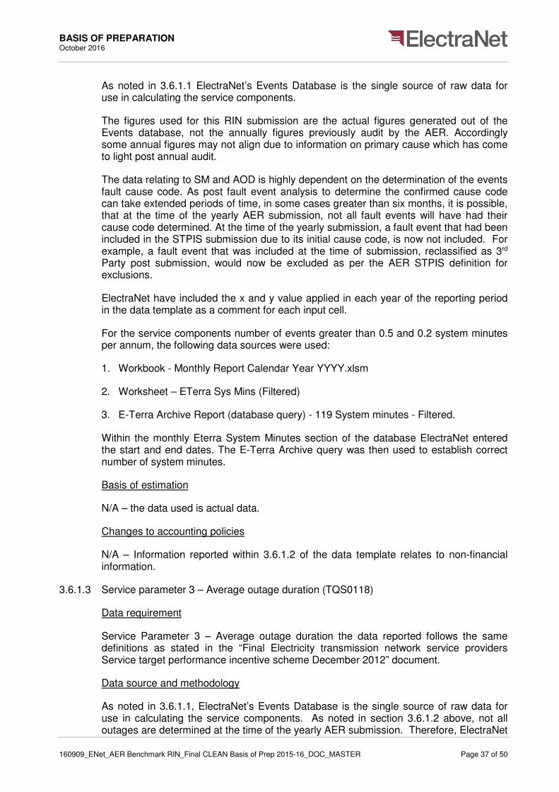
BASIS OF PREPARATION October 2016
160909_ENet_AER Benchmark RIN_Final CLEAN Basis of Prep 2015-16_DOC_MASTER Page 37 of 50
As noted in 3.6.1.1 ElectraNet’s Events Database is the single source of raw data for use in calculating the service components.
The figures used for this RIN submission are the actual figures generated out of the Events database, not the annually figures previously audit by the AER. Accordingly some annual figures may not align due to information on primary cause which has come to light post annual audit.
The data relating to SM and AOD is highly dependent on the determination of the events fault cause code. As post fault event analysis to determine the confirmed cause code can take extended periods of time, in some cases greater than six months, it is possible, that at the time of the yearly AER submission, not all fault events will have had their cause code determined. At the time of the yearly submission, a fault event that had been included in the STPIS submission due to its initial cause code, is now not included. For example, a fault event that was included at the time of submission, reclassified as 3rd Party post submission, would now be excluded as per the AER STPIS definition for exclusions.
ElectraNet have included the x and y value applied in each year of the reporting period in the data template as a comment for each input cell.
For the service components number of events greater than 0.5 and 0.2 system minutes per annum, the following data sources were used:
1. Workbook - Monthly Report Calendar Year YYYY.xlsm
2. Worksheet – ETerra Sys Mins (Filtered)
3. E-Terra Archive Report (database query) - 119 System minutes - Filtered.
Within the monthly Eterra System Minutes section of the database ElectraNet entered the start and end dates. The E-Terra Archive query was then used to establish correct number of system minutes.
Basis of estimation
N/A – the data used is actual data.
Changes to accounting policies
N/A – Information reported within 3.6.1.2 of the data template relates to non-financial information.
3.6.1.3 Service parameter 3 – Average outage duration (TQS0118)
Data requirement
Service Parameter 3 – Average outage duration the data reported follows the same definitions as stated in the “Final Electricity transmission network service providers Service target performance incentive scheme December 2012” document.
Data source and methodology
As noted in 3.6.1.1, ElectraNet’s Events Database is the single source of raw data for use in calculating the service components. As noted in section 3.6.1.2 above, not all outages are determined at the time of the yearly AER submission. Therefore, ElectraNet

BASIS OF PREPARATION October 2016
160909_ENet_AER Benchmark RIN_Final CLEAN Basis of Prep 2015-16_DOC_MASTER Page 38 of 50
are of the opinion that the Events database will provide the best available source of actual data into the future for service components TQS0118, the following supporting documentation was used:
• Workbook - Monthly Report Calendar Year YYYY.xlsm
• Worksheet – ETerra Sys Mins (Filtered)
• E-Terra Archive Report (database query) - 119 System minutes - Filtered.
Start and end dates were defined to establish average outage durations.
Basis of estimation
N/A – the data used is actual data.
Changes to accounting policies
N/A – Information reported within 3.6.1.3 of the data template relates to non-financial information.
3.6.1.4 System parameter – Proper operation of equipment – number of failure events (TQS0119-TQS0121)
Data requirement
Quality of services must be reported in accordance with the definitions specified in the December 2012 electricity transmission network service providers service target performance incentive scheme documents dated December 2012 (the STPIS documents).
Number of failures of protection systems
As defined on page 26 of the STPIS documents::
“Protection system failure events” are those events where the relevant protection equipment does not operate for a fault event as designed or where the relevant equipment operates when there is no relevant fault rate.
Material failure of SCADA system
As defined on page 26 of the STPIS documents;
The number of SCADA failures per annum as notified to the TNSP by the Australian Energy Market Operator (AEMO) on a monthly basis in the SCADA Minutes Lost report.
Incorrect operational isolation of primary or secondary equipment
As defined on page 26 of the STPIS documents:
The number of “incorrect operational isolation events” per annum where “incorrect operational isolation events” are those events where primary or secondary equipment was not been properly isolated during scheduled or emergency maintenance, irrespective of whether an outage occurred as a result.

BASIS OF PREPARATION October 2016
160909_ENet_AER Benchmark RIN_Final CLEAN Basis of Prep 2015-16_DOC_MASTER Page 39 of 50
ElectraNet has provided data on quality of services on the basis above which is consistent with the requirements of the AER Benchmarking regulatory information notice.
Data source and methodology
Number of failures of protection systems
A network event is managed by ElectraNet’s System Monitoring and Switching Centre (SMSC) who log the event in ElectraNet’s Events Database. ElectraNet’s fault investigation team review the event and record the results in a fault investigation report. The root cause analysis (RCA) in the fault investigation report identifies if the event is a failure of a protection system.
The Incorrect Protection Operation Count from WebQuery run each month on the Events Database to extract all failure events that occurred. The number of events that occurred for the month is entered in the monthly STPIS and MITC performance reports. The number of events identified in the monthly STPIS performance report for each calendar year has been totalled to determine the total per annum events for the each period.
Material failure of SCADA system
AEMO provides to ElectraNet on a monthly basis the SCADA minutes lost report which is reported in ElectraNet’s monthly STPIS and MITC performance reports. The number of events identified in the monthly STPIS performance report for each calendar year has been totalled to determine the total per annum events for the each period.
Incorrect operational isolation of primary or secondary equipment
Suspected switching incidents associated with primary plant are advised by field technicians to ElectraNet’s System Monitoring and Switching Centre (SMSC) who in turn advise the ElectraNet Switching Committee that a switching incident may have occurred. The Switching Committee’s role is to investigate reported events to establish if a switching incident has actually occurred.
In the case that a switching incident where primary plant is not isolated has occurred, it is reported in the monthly STPIS and MITC performance reports. The number of events identified in the monthly STPIS performance report for each calendar year has been totalled to determine the total per annum events for the each period.
Incorrect isolation events associated with secondary systems are recorded in ElectraNet’s Events Database. The SMSC daily log managed within the Events Database records the details of any event where secondary equipment has not been isolated.
To establish the number of incorrect operational isolation events per annum associated with secondary systems, ElectraNet reviewed the SMSC daily log within the Events Database. For each calendar year the number of identified incorrect isolation events identified associated with secondary systems was totalled.
Basis of estimation
Number of failures of protection systems (TQS0119)

BASIS OF PREPARATION October 2016
160909_ENet_AER Benchmark RIN_Final CLEAN Basis of Prep 2015-16_DOC_MASTER Page 40 of 50
No estimations have been made in the compilation of the number of failures of protection systems.
Material failure of SCADA system
No estimations have been made in the compilation of the number of material SCADA system failure events. Whilst material SCADA system failure events historically have not been a performance parameter applicable to TNSPs under STPIS, this information has been collected on a monthly basis over the benchmarking RIN back-cast period as part of existing business performance reporting.
Incorrect operational isolation of primary or secondary equipment
No estimations have been made in the compilation of the number of incorrect isolation events. Whilst incorrect operational isolation of primary and secondary events historically have not been a performance parameter applicable to TNSPs under STPIS, this information has been collected on a monthly basis over the benchmarking RIN back-cast period as part of existing business performance reporting.
Changes to accounting policies
N/A – Information reported within 3.6.1.4 of the data template relates to non-financial information.
3.6.2 Market impact component
3.6.2.1 Data requirement
ElectraNet is required to report the MIC Data in accordance with the definitions specified in the December 2012 Electricity Transmission Network Service Providers Service Target Performance Incentive Scheme (STPIS) document December 2012 Version 4. The difference with respect to MIC between earlier Versions and Version 4 is that “Coordinated Generator Outages” are excludable in earlier Versions but not in Version 4.
3.6.2.2 Data source and methodology
ElectraNet’s MITC Events Database is the source of data from which the report “AER Submission Details by Date Range” is produced on a yearly basis. The “AER Submission Details by Date Range” report summarises the included and excluded constraint Dispatch Intervals in a year.
ElectraNet’s “AER Submission Details by Date Range” yearly report has been used to find, by filtering, the number of “Coordinated Generator Outages” related Dispatch Intervals that have been excluded in the year.
3.6.2.3 Basis of estimation
N/A
3.6.2.4 Changes to accounting policies
N/A

BASIS OF PREPARATION October 2016
160909_ENet_AER Benchmark RIN_Final CLEAN Basis of Prep 2015-16_DOC_MASTER Page 41 of 50
3.6.3 System losses
3.6.3.1 Data requirement
ElectraNet must report system losses in accordance with the definitions specified in the Economic Benchmarking RIN for Transmission Network Services Providers Instruction and Definitions November 2013 Chapter 7 Section 7.3 System losses.
3.6.3.2 Data source and methodology
National Grid Metering (NGM) data on which the NEM financial settlement is based has been used. This has been previously Quality Controlled by the Metering Data Agent (meter reader) and by AEMO prior to use in NEM settlement. It is also checked weekly by ElectraNet’s internal processes for reasonableness of Transmission Loss Factor.
All data is sourced from NGM Data extracted from the ElectraNet Oracle database to an Excel spreadsheet pivot table where the Data Slicer is used to extract data by Financial Year and by classification of:
• Interconnectors; and
• Load connections: Wholesale (directly connected end-users) and Distribution.
The extracted data is used to calculate the required RIN parameters on yearly basis via appropriate formulae, following the RIN Instructions and Definitions Chapter 7 Section 7.3 wherever appropriate, in an Excel workbook.
3.6.3.3 Basis of estimation
No estimations have been required.
3.6.3.4 Changes to accounting policies
N/A
3.7 Operating Environment
3.7.1 Terrain factors
3.7.1.1 Data requirement
Complete the table in accordance with the definitions provided in chapter 9.
If ElectraNet records poles rather than spans, the number of spans is the number of poles less one.
The AER require the following Variables:
• Number of vegetation Maintenance Spans
• Average Number Of Trees Per Maintenance Span
• Average number of Defects per vegetation Maintenance Span
• Tropical proportion

BASIS OF PREPARATION October 2016
160909_ENet_AER Benchmark RIN_Final CLEAN Basis of Prep 2015-16_DOC_MASTER Page 42 of 50
• Standard Vehicle Access
• Altitude
• Bushfire risk
If ElectraNet has Actual Information, ElectraNet must report all years of available data. If ElectraNet does not have actual information on these variables, then it must estimate data for the most recent Regulatory Year.
Number of vegetation Maintenance Spans
The total count of spans in the network that are subject to vegetation management practices in the relevant year. If ElectraNet records towers rather than spans, the number of spans is the number of towers less one. A maintenance span is defined as a span in ElectraNet's network that is subject to active vegetation management practices in the relevant year. Active vegetation management practices do not include Inspection of vegetation Maintenance Spans.
Average vegetation maintenance span cycle
If there is no available data for the ‘average vegetation maintenance span cycle’ variable, ElectraNet is required to estimate five years of back cast data. The average vegetation Maintenance Span Cycle (defined as the planned number of years between which cyclic vegetation maintenance is performed) can be calculated based on a simple average of all the Maintenance Span Cycles.
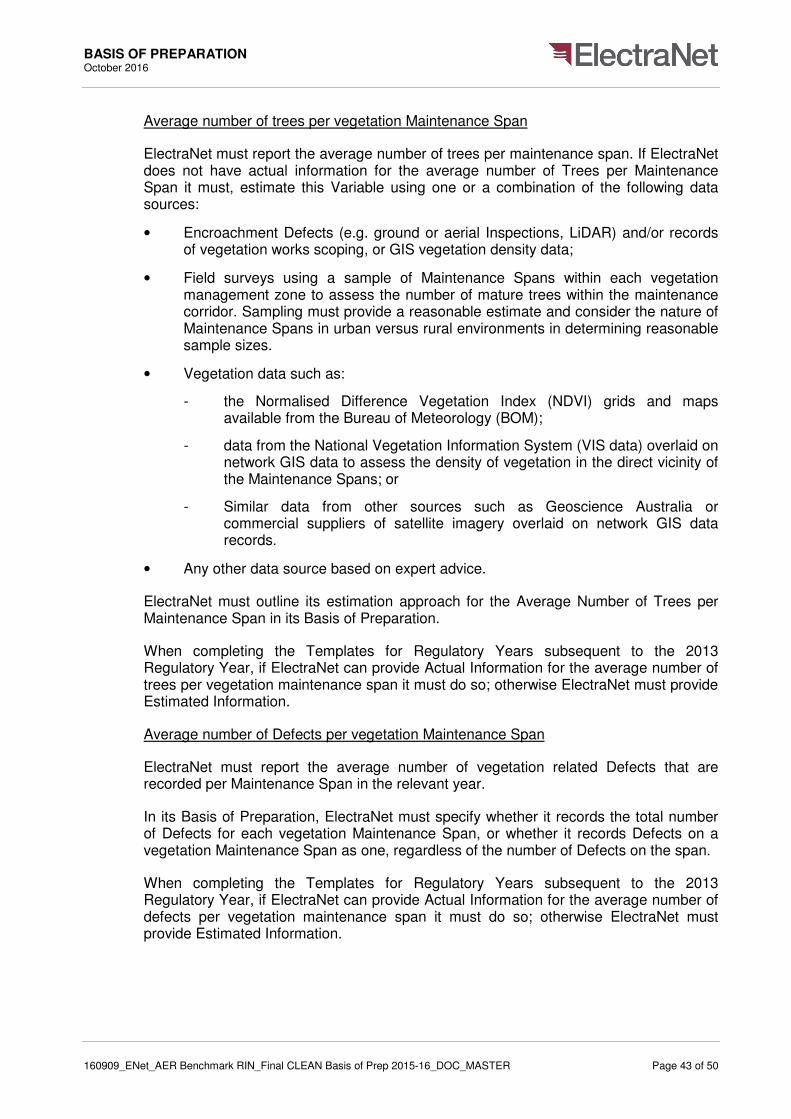
BASIS OF PREPARATION October 2016
160909_ENet_AER Benchmark RIN_Final CLEAN Basis of Prep 2015-16_DOC_MASTER Page 43 of 50
Average number of trees per vegetation Maintenance Span
ElectraNet must report the average number of trees per maintenance span. If ElectraNet does not have actual information for the average number of Trees per Maintenance Span it must, estimate this Variable using one or a combination of the following data sources:
• Encroachment Defects (e.g. ground or aerial Inspections, LiDAR) and/or records of vegetation works scoping, or GIS vegetation density data;
• Field surveys using a sample of Maintenance Spans within each vegetation management zone to assess the number of mature trees within the maintenance corridor. Sampling must provide a reasonable estimate and consider the nature of Maintenance Spans in urban versus rural environments in determining reasonable sample sizes.
• Vegetation data such as:
- the Normalised Difference Vegetation Index (NDVI) grids and maps available from the Bureau of Meteorology (BOM);
- data from the National Vegetation Information System (VIS data) overlaid on network GIS data to assess the density of vegetation in the direct vicinity of the Maintenance Spans; or
- Similar data from other sources such as Geoscience Australia or commercial suppliers of satellite imagery overlaid on network GIS data records.
• Any other data source based on expert advice.
ElectraNet must outline its estimation approach for the Average Number of Trees per Maintenance Span in its Basis of Preparation.
When completing the Templates for Regulatory Years subsequent to the 2013 Regulatory Year, if ElectraNet can provide Actual Information for the average number of trees per vegetation maintenance span it must do so; otherwise ElectraNet must provide Estimated Information.
Average number of Defects per vegetation Maintenance Span
ElectraNet must report the average number of vegetation related Defects that are recorded per Maintenance Span in the relevant year.
In its Basis of Preparation, ElectraNet must specify whether it records the total number of Defects for each vegetation Maintenance Span, or whether it records Defects on a vegetation Maintenance Span as one, regardless of the number of Defects on the span.
When completing the Templates for Regulatory Years subsequent to the 2013 Regulatory Year, if ElectraNet can provide Actual Information for the average number of defects per vegetation maintenance span it must do so; otherwise ElectraNet must provide Estimated Information.

BASIS OF PREPARATION October 2016
160909_ENet_AER Benchmark RIN_Final CLEAN Basis of Prep 2015-16_DOC_MASTER Page 44 of 50
Tropical spans
The tropical spans are the approximate total number of urban and rural Maintenance Spans in the Hot Humid Summer and Warm Humid Summer regions as defined by the Australian Bureau of Meteorology Australian Climatic Zones map (based on temperature and humidity).
When completing the Templates for Regulatory Years subsequent to the 2013 Regulatory Year, if ElectraNet can provide Actual Information for tropical spans it must do so; otherwise ElectraNet must provide Estimated Information.
Standard vehicle access
Areas with Standard Vehicle Access are serviced through made roads, gravel roads and open paddocks (including gated and fenced paddocks). An area with no Standard Vehicle Access would not be accessible by a two wheel drive vehicle. The intended unit of measure for the in the economic benchmarking RIN is the km of route line length that does not have standard vehicle access.
Altitude
The Route Line Length that is 600 metres above sea level.
Bushfire risk
The bushfire risk Variable is the number of Maintenance Spans in high bushfire risk areas as classified by a person or organisation with appropriate expertise on fire risk. This includes but is not limited to:
• ElectraNet’s jurisdictional fire authority
• local councils
• insurance companies
• ElectraNet’s consultants
• Local fire experts
When completing the Templates for Regulatory Years subsequent to the 2013 Regulatory Year, if ElectraNet can provide Actual Information for bushfire risk it must do so; otherwise ElectraNet must provide Estimated Information.
3.7.1.2 Data source and methodology
Number of Vegetation Maintenance Spans
ElectraNet in establishing total number of vegetation maintenance spans, average number of trees per span defects and bushfire risk relied on information estimated by the vegetation maintenance contractor.
A maintenance Span is defined as a span in ElectraNet's network that is subject to active vegetation management practices during the relevant year. ElectraNet has included spans requiring tree trimming, removal or scrub removal, but does not include inspection or measuring of vegetation in spans. This is based on expert advice from ElectraNet’s vegetation maintenance contractor.
BASIS OF PREPARATION October 2016
160909_ENet_AER Benchmark RIN_Final CLEAN Basis of Prep 2015-16_DOC_MASTER Page 45 of 50
To establish the total number of maintenance spans, ElectraNet have been advised that the contractor reviewed an Access database which contains collated data from their inspector and cutting crew worksheets for the regulatory year. This data provided the number of spans that are actively managed by the contractor during the year.
Average vegetation maintenance span cycle
ElectraNet operates under more than one vegetation maintenance span cycle. Routinely, ElectraNet actively manages all spans on a 3 year cycle. However, for spans in bushfire and high bushfire risk areas, ElectraNet also performs pre-bushfire season vegetation maintenance on an annual basis.
Therefore to reasonably estimate the average vegetation maintenance span cycle, the number of bushfire spans as a proportion of total spans for the regulatory year was determined and a weighted average span cycle calculated for all spans.
Average number of trees per vegetation maintenance span
Average number of trees per span has been estimated based on expert advice from vegetation maintenance contractor. ElectraNet were advised that the contractor sourced information on number of trees per span from an Access database which provides collated information from daily worksheets from inspectors and cutting crews for the regulatory year.
To estimate the number of trees per vegetation span, ElectraNet were advised that the contractor took the number of trees actively maintained (trimmed, removed or scrub removal) divided by the number of spans requiring vegetation maintenance.
Average number of defects per vegetation maintenance span
Average number of defects per span was estimated based on advice from vegetation maintenance contractor. The contractor estimated the average number of defects per vegetation maintenance span by reviewing information for the regulatory year in an Access database which provides collated daily worksheet information from inspectors and cutting crews.
Note that ElectraNet records the total number of defects for each vegetation maintenance span. The contractor’s records identified the total number of defect spans inspected and total number of trees actively maintained (removed or scrub removed) in defect spans.
Average number of defects per vegetation maintenance span is the number of trees actively maintained (removed or scrub removal) in these defect spans divided by the number of vegetation maintenance spans. Defect spans are defined as Z code (fire risk) encroachment defects.
Tropical Proportion
The Australian Bureau of Meteorology (BOM) Australian Climatic Zones map (based on temperature and humidity) was used to determine the number of spans in hot humid summer and warm humid summer regions. Link to the zone map is below:
http://www.bom.gov.au/jsp/ncc/climate_averages/climate-classifications/index.jsp

BASIS OF PREPARATION October 2016
160909_ENet_AER Benchmark RIN_Final CLEAN Basis of Prep 2015-16_DOC_MASTER Page 46 of 50
ElectraNet reviewed the Climatic Zone map to assess the number of spans ElectraNet has within hot humid summer or warm humid summer climate zones. Based on this assessment, ElectraNet can confirm that 0% proportion of spans is in in hot humid summer and warm humid summer regions.
A copy of the Australian Climatic Zones map used to review the ElectraNet network is included as Figure 3-3: Climate Zones Based on Temperature and Humidity below:
Figure 3-3: Climate Zones Based on Temperature and Humidity
Standard vehicle access - kms
Information for standard vehicle access was sourced from road information from South Australian Government Data Directory (once loaded into the GIS) as well as ElectraNet’s internal network data for the GIS system.
Note that reporting standard vehicle access kilometres in ElectaNet’s case is likely to be of limited value to the AER as all ElectraNet’s access easements are only accessible by diesel vehicles due to bushfire risk consistent with ElectraNet policy. ElectraNet’s vehicle fleet is almost entirely made up of diesel 4WD vehicles and these are the only type of vehicle used by ElectraNet and its contractors to access asset easements.
However, for the purposes of this response, ElectraNet have calculated standard vehicle access as being the route length that is not able to be accessed by a 2WD vehicle.
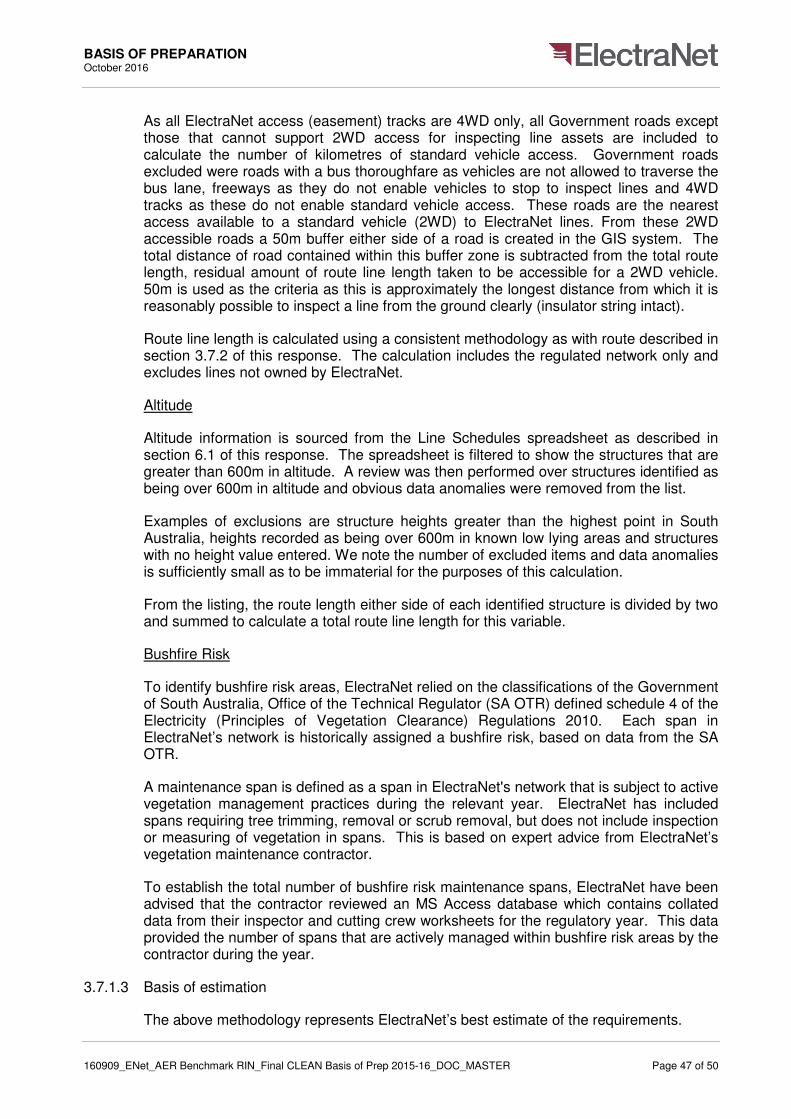
BASIS OF PREPARATION October 2016
160909_ENet_AER Benchmark RIN_Final CLEAN Basis of Prep 2015-16_DOC_MASTER Page 47 of 50
As all ElectraNet access (easement) tracks are 4WD only, all Government roads except those that cannot support 2WD access for inspecting line assets are included to calculate the number of kilometres of standard vehicle access. Government roads excluded were roads with a bus thoroughfare as vehicles are not allowed to traverse the bus lane, freeways as they do not enable vehicles to stop to inspect lines and 4WD tracks as these do not enable standard vehicle access. These roads are the nearest access available to a standard vehicle (2WD) to ElectraNet lines. From these 2WD accessible roads a 50m buffer either side of a road is created in the GIS system. The total distance of road contained within this buffer zone is subtracted from the total route length, residual amount of route line length taken to be accessible for a 2WD vehicle. 50m is used as the criteria as this is approximately the longest distance from which it is reasonably possible to inspect a line from the ground clearly (insulator string intact).
Route line length is calculated using a consistent methodology as with route described in section 3.7.2 of this response. The calculation includes the regulated network only and excludes lines not owned by ElectraNet.
Altitude
Altitude information is sourced from the Line Schedules spreadsheet as described in section 6.1 of this response. The spreadsheet is filtered to show the structures that are greater than 600m in altitude. A review was then performed over structures identified as being over 600m in altitude and obvious data anomalies were removed from the list.
Examples of exclusions are structure heights greater than the highest point in South Australia, heights recorded as being over 600m in known low lying areas and structures with no height value entered. We note the number of excluded items and data anomalies is sufficiently small as to be immaterial for the purposes of this calculation.
From the listing, the route length either side of each identified structure is divided by two and summed to calculate a total route line length for this variable.
Bushfire Risk
To identify bushfire risk areas, ElectraNet relied on the classifications of the Government of South Australia, Office of the Technical Regulator (SA OTR) defined schedule 4 of the Electricity (Principles of Vegetation Clearance) Regulations 2010. Each span in ElectraNet’s network is historically assigned a bushfire risk, based on data from the SA OTR.
A maintenance span is defined as a span in ElectraNet's network that is subject to active vegetation management practices during the relevant year. ElectraNet has included spans requiring tree trimming, removal or scrub removal, but does not include inspection or measuring of vegetation in spans. This is based on expert advice from ElectraNet’s vegetation maintenance contractor.
To establish the total number of bushfire risk maintenance spans, ElectraNet have been advised that the contractor reviewed an MS Access database which contains collated data from their inspector and cutting crew worksheets for the regulatory year. This data provided the number of spans that are actively managed within bushfire risk areas by the contractor during the year.
3.7.1.3 Basis of estimation
The above methodology represents ElectraNet’s best estimate of the requirements.
BASIS OF PREPARATION October 2016
160909_ENet_AER Benchmark RIN_Final CLEAN Basis of Prep 2015-16_DOC_MASTER Page 48 of 50
As ElectraNet contracts out vegetation maintenance activities, therefore, ElectraNet have had to rely on estimated information from the contractor to provide the data requirements.
Average number of trees per vegetation maintenance span
Note that this is an approximation and therefore this parameter is not provided to 4 significant figures.
Average number of defects per vegetation maintenance span
Number of trees (collated through daily worksheets from inspectors/cutting crews for the period) is an approximation. Hence this parameter is not provided to 4 significant figures.
Note all the variables are reported as at the end of the regulatory year.
3.7.1.4 Changes to accounting policies
N/A – Information reported within 3.7.1 of the data template relates to non-financial information.
3.7.2 Network characteristics
3.7.2.1 Data requirement
Route line length
ElectraNet must input the route line length of lines for ElectraNet’s network. This is based on the distance between line segments and does not include vertical components such as line sag. The route line length does not necessarily equate to the circuit length as the circuit length may include multiple circuits.
Variability of Dispatch
ElectraNet must input the Variability of dispatch. This is the proportion of energy dispatch from non-thermal generators.
Concentrated load distance
ElectraNet must input the concentrated load distance. This is the greatest distance (Route Line Length) from node having at least 30 per cent of generation capacity to node having at least 30 per cent of load, where a node is a connection point from a generation source or location to the (transmission) network at source end and a connection point to a load or distribution system at the destination end.
Where there is no concentrated source or load above 30 per cent, respond relative to the largest concentrated source and load and indicate the generation and load magnitudes.
Total number of spans
ElectraNet must input the total number of spans.

BASIS OF PREPARATION October 2016
160909_ENet_AER Benchmark RIN_Final CLEAN Basis of Prep 2015-16_DOC_MASTER Page 49 of 50
3.7.2.2 Data source and methodology
Route line length)
Route line length data has been sourced from the same spreadsheet as the circuit length pivot sheet as described in ElectraNet’s response in section 3.5. Single circuit kilometres were totalled for each voltage. Note that double and triple circuits were excluded from the listing, as per the AER requirement to report true route line length (not necessarily equal to circuit length).
The filtered spreadsheet only included route line length for regulated lines and de-energised lines. Cables have been excluded from the calculation.
Variability of Dispatch
A grid entry metering report was run from SAMarket which is an SQL database viewer, which shows thermal (Power Station) versus non-thermal (Wind Farm) energy generation for each half hour time period for the regulatory year.
ElectraNet divided the total sum of Wind Farm energy generation by the total sum of all Wind Farm energy generation and Power Station energy (as classified in SA Market) generation. This analysis excluded the Interconnector. For example, all generators included in the 2012/13 RIN year are listed in Figure 3-4: SA Generators on the following page:
Figure 3-4: SA Generators

BASIS OF PREPARATION October 2016
160909_ENet_AER Benchmark RIN_Final CLEAN Basis of Prep 2015-16_DOC_MASTER Page 50 of 50
Concentrated Load Distance
In past years ElectraNet has entered 0 km for this variable, due to our largest generating node and loads (measured by AMD or installed capacity) being effectively coincident (Metro Generation to Metro Load linked via a meshed distribution network). With the mothballing of Metro Generation, this becomes less representative of the ElectraNet network as a whole, as installed capacity still remains but the energy production is reduced. Similarly the greatest distance in route line length between nodes is unsuited to a meshed network context, as this figure can be very large.
Due to these issues ElectraNet have decided to provide the shortest route line length between the largest generating and the largest load node (as measured by energy).
A load node is also inclusive of meshed (subsystem) connection points if applicable, which despite being fed from geographically separate points is the same load electrically under system normal conditions.
Interconnectors are classified as either a load or generator depending on the duration that they are in import or export.
Total Number of Spans
Total number of spans is calculated from the same spreadsheet as circuit lengths as described in section 3.5 of this response. The spreadsheet was filtered to identify the number of individual spans which were then totalled to identify the total number of spans for each regulatory year.
The filtered spreadsheet only included route line length for regulated lines and de-energised lines only. Cables and have been excluded from the calculation.
3.7.2.3 Basis of estimation
N/A
3.7.2.4 Changes to accounting policies
N/A – Information reported within 3.7.2 of the data template relates to non-financial information.