Embed Size (px)
Citation preview

1

2
Chap 7 Resistance and Powering of Ship
Objectives
• Prediction of Ship’s Power- Ship’s driving system and concept of power- Resistance of ship and its components
· frictional resistance· wave-making resistance· others
- Froude expansion- Effective horse power calculation
• Propeller Theory- Propeller components and definitions- Propeller theory- Cavitation

3
Ship Drive Train and Power
Ship Drive Train System
Engine ReductionGear Bearing Seals
ScrewStrut
BHP SHP DHP
THP
EHP
4
Brake Horse Power (BHP)
- Power output at the shaft coming out of the engine before
the reduction gears
Shaft Horse Power (SHP)
- Power output after the reduction gears
- SHP=BHP - losses in reduction gear
Horse Power in Drive Train
Ship Drive Train and Power

5
Delivered Horse Power (DHP)- Power delivered to the propeller- DHP=SHP – losses in shafting, shaft bearings and seals
Thrust Horse Power (THP)- Power created by the screw/propeller- THP=DHP – Propeller losses
Relative Magnitudes
BHP>SHP>DHP>THP>EHP
E/G R/GBHP SHP Shaft
Bearing Prop.DHP THP EHP
Hull
Ship Drive Train and Power

6
Effective Horse Power (EHP)
• EHP : The power required to move the ship hull at a given speed in the absence of propeller action
(EHP is not related with Power Train System)• EHP can be determined from the towing tank experiments at
the various speeds of the model ship.• EHP of the model ship is converted into EHP of the full scale
ship by Froude’s Law.
VTowing Tank Towing carriage
Measured EHP

7
Effective Horse Power (EHP)
0
200
400
600
800
1000
Effe
ctiv
e H
orse
pow
er, E
HP
(HP
)
0 2 4 6 8 10 12 14 16 Ship Speed, Vs (Knots)
POWER CURVEYARD PATROL CRAFT
Typical EHP Curve of YP
8
Effective Horse Power (EHP)
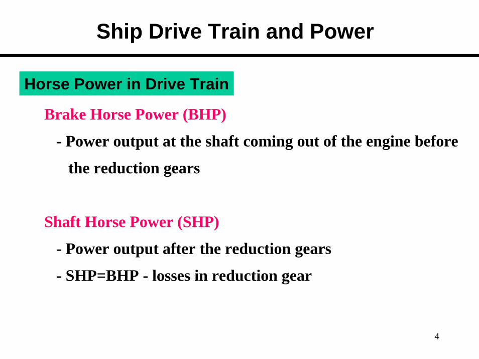
Efficiencies• Hull Efficiency
THPEHP
H =η
- Hull efficiency changes due to hull-propeller interactions.- Well-designed ship : - Poorly-designed ship :
1fHη1pHη
Well-designed
Poorly-designed- Flow is not smooth.- THP is reduced.- High THP is neededto get designed speed.
9
Screw
Effective Horse Power (EHP)
Efficiencies (cont’d)
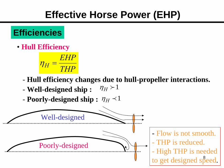
• Propeller Efficiency
DHPTHP
propeller =η
• Propulsive Coefficients (PC)
SHPEHP
p =η
propeller designed for well 6.0≈pη
SHP DHP
THP
EHP
10
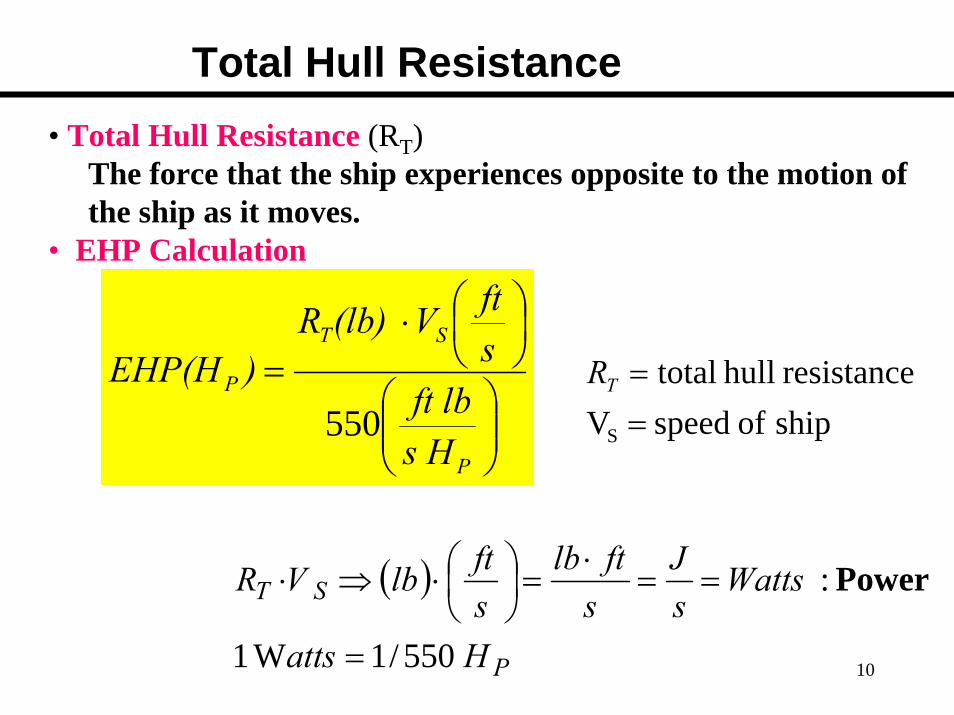
Total Hull Resistance• Total Hull Resistance (RT)
The force that the ship experiences opposite to the motion of the ship as it moves.
• EHP Calculation
⎟⎟⎠
⎞⎜⎜⎝
⎛
⎟⎠⎞
⎜⎝⎛⋅
=
P
ST
P
s Hft lb
sftV(lb) R
)EHP(H550 ship of speedV
resistance hull total
S ==TR
( )
P
ST
Hatts
WattssJ
sftlb
sftlbVR
550/1W 1
:
=
==⋅
=⎟⎠⎞
⎜⎝⎛⋅⇒⋅ Power

11
Total Hull Resistance (cont)
• Coefficient of Total Hull Resistance
- Non-dimensional value of total resistance
5.0 2 SV
RCs
TT ρ=
hull submerged theon area surface wettedship of Speed
density Fluid resistance hull Total
watercalm in resistance hull totaloft Coefficien
=====
SV
RC
S
T
T
ρ
dimension-nonlb 2
2
4
2⇐
⎟⎟⎠
⎞⎜⎜⎝
⎛⎟⎟⎠
⎞⎜⎜⎝
⎛ ⋅⇒
ftsft
ftslb

12
Total Hull Resistance (cont)
• Coefficient of Total Hull Resistance (cont’d)
-Total Resistance of full scale ship can be determined using
ST VSC , , andρ
TST CSVlbR ⋅= 25.0)( ρ
speed ship scale Fullform of Curves from obtained
table property water from availabletest model the by determined
: : : :
S
T
VS
Cρ
13
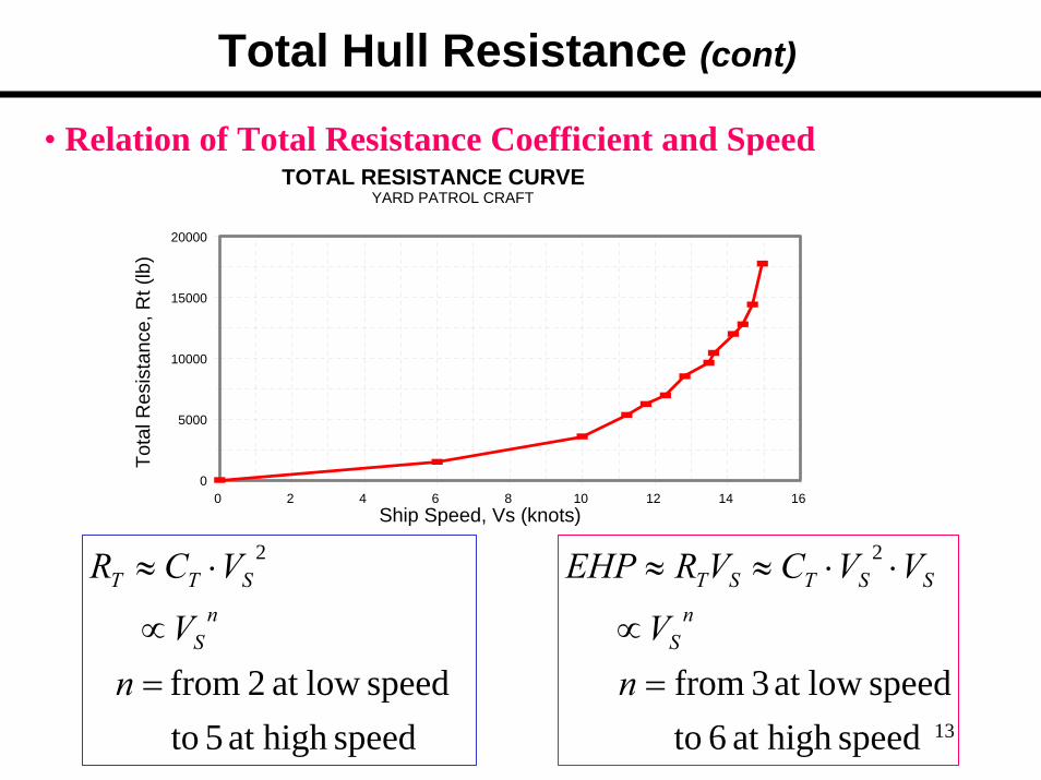
Total Hull Resistance (cont)
• Relation of Total Resistance Coefficient and Speed
0
5000
10000
15000
20000
Tota
l Res
ista
nce,
Rt (
lb)
0 2 4 6 8 10 12 14 16 Ship Speed, Vs (knots)
TOTAL RESISTANCE CURVEYARD PATROL CRAFT
speed highat 5 o t speedlow at 2 from
2
=∝
⋅≈
nV
VCRn
S
STT
speed highat 6 to speedlow at 3 from
2
=∝
⋅⋅≈≈
nV
VVCVREHPn
S
SSTST

14
Components of Total Resistance
• Total Resistance
AWVT RRRR ++=Resistance Viscous: RV
Resistance Making Wave: RWResistance Air: RA
• Viscous Resistance- Resistance due to the viscous stresses that the fluid exertson the hull.( due to friction of the water against the surface of the ship)
- Viscosity, ship’s velocity, wetted surface area of ship generally affect the viscous resistance.
15
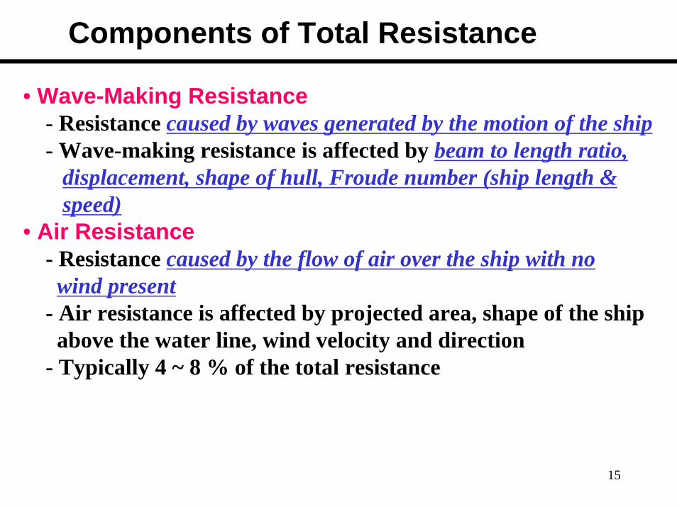
Components of Total Resistance
• Wave-Making Resistance- Resistance caused by waves generated by the motion of the ship- Wave-making resistance is affected by beam to length ratio,
displacement, shape of hull, Froude number (ship length & speed)
• Air Resistance- Resistance caused by the flow of air over the ship with nowind present
- Air resistance is affected by projected area, shape of the shipabove the water line, wind velocity and direction
- Typically 4 ~ 8 % of the total resistance

16
Components of Total Hull Resistance• Total Resistance and Relative Magnitude of Components
Viscous
Air Resistance
Wave-making
Speed (kts)
Res
ista
nce
(lb)
- Low speed : Viscous R- Higher speed : Wave-making R- Hump (Hollow) : location is function of ship length and speed.
HumpHollow

17
Why is a Golf Ball Dimpled?
• Let’s look at a Baseball (because that’s what I have numbers for)– At the velocities of 50 to 130 mph dominant in baseball the air
passes over a smooth ball in a highly resistant flow.– Turbulent flow does not occur until nearly 200 mph for a smooth
ball– A rough ball (say one with raised stitches like a baseball) induces
turbulent flow
– A baseball batted 400 feet would only travel 300 feet if it was smooth.
– A non-dimpled golf ball would really hamper Tiger Woods’ long game

18
Coefficient of Viscous Resistance
• Viscous Flow around a ship
Real ship : Turbulent flow exists near the bow.Model ship : Studs or sand strips are attached at the bow
to create the turbulent flow.
19
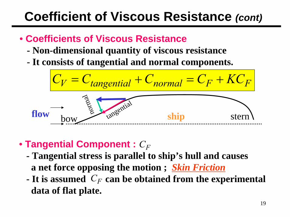
Coefficient of Viscous Resistance (cont)
• Coefficients of Viscous Resistance- Non-dimensional quantity of viscous resistance- It consists of tangential and normal components.
FF KCC +=+= normaltangentialV CCC
• Tangential Component :- Tangential stress is parallel to ship’s hull and causes a net force opposing the motion ; Skin Friction
- It is assumed can be obtained from the experimental data of flat plate.
FC
flow shipbow sterntangentialno
rmal
FC

20
Coefficient of Viscous Resistance (cont)
νS
n
nF
FV
LVR
RC
CC
=
−=
=
)2(log075.0
210
of Component Tangential
Semi-empiricalequation
watersalt for water freshfor
/sft101.2791/sft101.2260
/s)(ft ViscosityKinematic
)Speed(ft/s Ship(ft)L
Number Reynolds
25-
25-
2
pp
×=
×=
=
=
==
νS
n
VL R

21
Coefficient of Viscous Resistance (cont)
• Tangential Component (cont’d)- Relation between viscous flow and Reynolds number
· Laminar flow : In laminar flow, the fluid flows in layers in an orderly fashion. The layers do not mix transverselybut slide over one another.
· Turbulent flow : In turbulent flow, the flow is chaotic and mixed transversely.
Laminar Flow Turbulent Flow5105×< about Rn
5105 ×> about Rn
Flow overflat plate
22
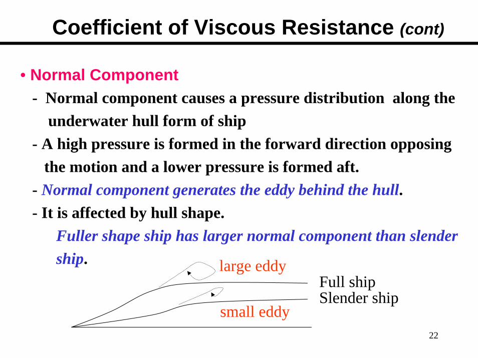
• Normal Component- Normal component causes a pressure distribution along the
underwater hull form of ship- A high pressure is formed in the forward direction opposing
the motion and a lower pressure is formed aft.- Normal component generates the eddy behind the hull.- It is affected by hull shape.
Fuller shape ship has larger normal component than slendership.
Full shipSlender ship
large eddy
small eddy
Coefficient of Viscous Resistance (cont)

23
• Normal Component (cont’d)
- It is calculated by the product of Skin Friction with Form Factor.
23
)()(
)()()()(ft 19 K
K
⎟⎟⎠
⎞⎜⎜⎝
⎛ ∇=
==
=
ftLftB
ftTftBftL
CCKC
F
Fv
Factor FormCoeff. Friction Skin
of Component Normal
Coefficient of Viscous Resistance (cont)

24
23
)()(
)()()()(ft 19 K ⎟⎟
⎠
⎞⎜⎜⎝
⎛ ∇=
ftLftB
ftTftBftL
FF C KC +=+= normaltangentialV CCC
210 )2(log
075.0−
=n
F RC
Summary of Viscous Resistance Coefficient
watersalt for water freshfor
/sft101.2791/sft101.2260
/s)(ft ViscosityKinematic
)Speed(ft/s Ship(ft)L
Number Reynolds
25-
25-
2
pp
×=
×=
=
=
==
=
ν
ν
S
n
Sn
VL R
LVR K= Form Factor
25
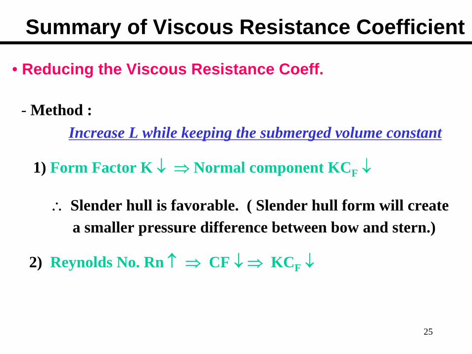
• Reducing the Viscous Resistance Coeff.
- Method : Increase L while keeping the submerged volume constant
1) Form Factor K ↓ ⇒ Normal component KCF ↓
∴ Slender hull is favorable. ( Slender hull form will create a smaller pressure difference between bow and stern.)
2) Reynolds No. Rn ↑ ⇒ CF ↓ ⇒ KCF ↓
Summary of Viscous Resistance Coefficient

26
Wave-Making Resistance
Typical Wave Pattern
Bow divergent waveBow divergent wave
Transverse waveL
Wave Length
Stern divergent wave

27
28
Wave-Making Resistance
Transverse wave System
• It travels at approximately the same speed as the ship.• At slow speed, several crests exist along the ship length
because the wave lengths are smaller than the ship length.• As the ship speeds up, the length of the transverse wave
increases.• When the transverse wave length approaches the ship length,
the wave making resistance increases very rapidly.This is the main reason for the dramatic increase in Total Resistance as speed increases.
29
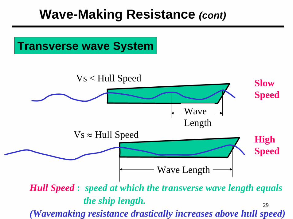
Wave-Making Resistance (cont)
Transverse wave System
Wave Length
WaveLength
SlowSpeed
HighSpeed
Vs < Hull Speed
Vs ≈ Hull Speed
Hull Speed : speed at which the transverse wave length equalsthe ship length.
(Wavemaking resistance drastically increases above hull speed)
30
Divergent Wave System
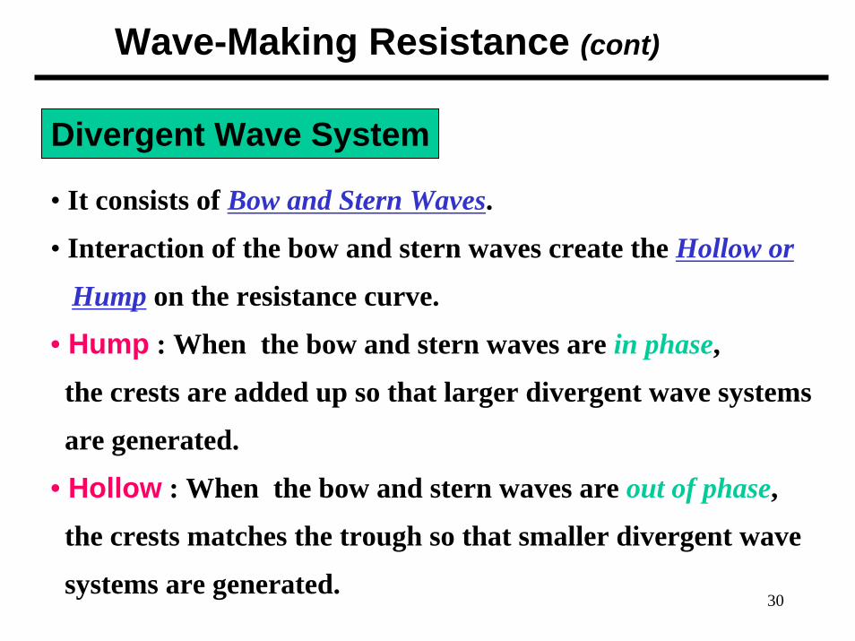
• It consists of Bow and Stern Waves.
• Interaction of the bow and stern waves create the Hollow or
Hump on the resistance curve.
• Hump : When the bow and stern waves are in phase,
the crests are added up so that larger divergent wave systems
are generated.
• Hollow : When the bow and stern waves are out of phase,
the crests matches the trough so that smaller divergent wave
systems are generated.
Wave-Making Resistance (cont)

31
Calculation of Wave-Making Resistance Coeff.• Wave-making resistance is affected by
- beam to length ratio- displacement- hull shape- Froude number
• The calculation of the coefficient is far difficult and inaccuratefrom any theoretical or empirical equation.(Because mathematical modeling of the flow around shipis very complex since there exists fluid-air boundary, wave-body interaction)
• Therefore model test in the towing tank and Froude expansionare needed to calculate the Cw of the real ship.
Wave-Making Resistance (cont)

32
Reducing Wave Making Resistance
1) Increasing ship length to reduce the transverse wave- Hull speed will increase.- Therefore increment of wave-making resistance of longer
ship will be small until the ship reaches to the hull speed. - EX :
FFG7 : ship length 408 ft Which ship requires morehull speed 27 KTS horse power at 35 KTS?
CVN65 : ship length 1040 fthull speed 43 KTS
Wave-Making Resistance (cont)

33
Reducing Wave Making Resistance (cont’d)
2) Attaching Bulbous Bow to reduce the bow divergent wave- Bulbous bow generates the second bow waves .- Then the waves interact with the bow wave resulting in
ideally no waves, practically smaller bow divergent waves. - EX :
DDG 51 : 7 % reduction in fuel consumption at cruise speed3% reduction at max speed.design &retrofit cost : less than $30 million life cycle fuel cost saving for all the ship : $250 mil.
Tankers & Containers : adopting the Bulbous bow
Wave-Making Resistance (cont)

34
Bulbous Bow
Wave-Making Resistance (cont)

35
Coefficient of Total Resistance
Allowancen Correlatio 1
: C CCK)(C
CCCC
A
AWF
AWVT
+++=++=
Coefficient of total hull resistance
Correlation Allowance• It accounts for hull resistance due to surface roughness,
paint roughness, corrosion, and fouling of the hull surface.• It is only used when a full-scale ship prediction of EHP is made
from model test results. • For model,• For ship, empirical formulas can be used.
. 0 smooth is surface model Since=AC
36
Other Type of Resistances
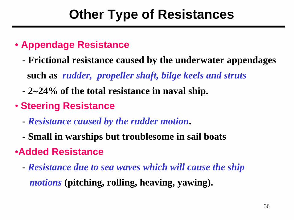
• Appendage Resistance- Frictional resistance caused by the underwater appendagessuch as rudder, propeller shaft, bilge keels and struts
- 2∼24% of the total resistance in naval ship.• Steering Resistance
- Resistance caused by the rudder motion.- Small in warships but troublesome in sail boats
•Added Resistance- Resistance due to sea waves which will cause the ship
motions (pitching, rolling, heaving, yawing).

37
Other Resistances
• Increased Resistance in Shallow Water- Resistance caused by shallow water effect
- Flow velocities under the hull increases in shallow water.
: Increment of frictional resistance due to the velocities
: Pressure drop, suction, increment of wetted surface area
→ Increases frictional resistance
- The waves created in shallow water take more energy from
the ship than they do in deep water for the same speed.
→ Increases wave making resistance
38
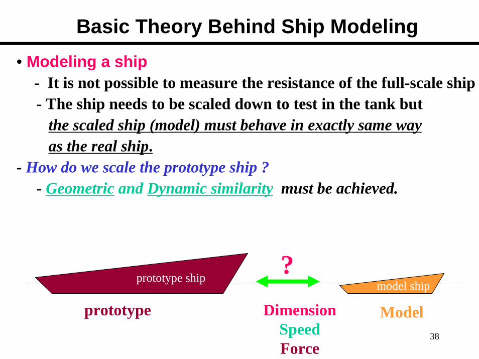
Basic Theory Behind Ship Modeling• Modeling a ship
- It is not possible to measure the resistance of the full-scale ship- The ship needs to be scaled down to test in the tank but
the scaled ship (model) must behave in exactly same wayas the real ship.
- How do we scale the prototype ship ?- Geometric and Dynamic similarity must be achieved.
?Dimension
SpeedForce
prototype Model
prototype shipmodel ship
39
Basic Theory behind Ship Modeling
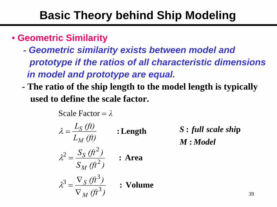
• Geometric Similarity- Geometric similarity exists between model and
prototype if the ratios of all characteristic dimensionsin model and prototype are equal.
- The ratio of the ship length to the model length is typicallyused to define the scale factor.
Volume :
Area :
:
Factor Scale
3
33
2
22
)(ft)(ft
)(ftS)(ftS
(ft)L(ft)L
λ
M
S
M
S
M
S
∇∇
=
=
=
=
λ
λ
λ Length ModelM
shi scale fullS :
p:
40
Basic Theory behind Ship Modeling
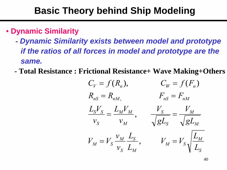
• Dynamic Similarity- Dynamic Similarity exists between model and prototype
if the ratios of all forces in model and prototype are thesame.
- Total Resistance : Frictional Resistance+ Wave Making+Others
S
MSM
M
S
S
MSM
M
M
S
S
M
MM
S
SS
nMnSnMnS
nWnV
LLVV
LL
vvVV
gLV
gLV
vVL
vVL
FFRRFfCRfC
==
==
====
,
,
)( ),(
,
41
Basic Theory behind Ship Modeling
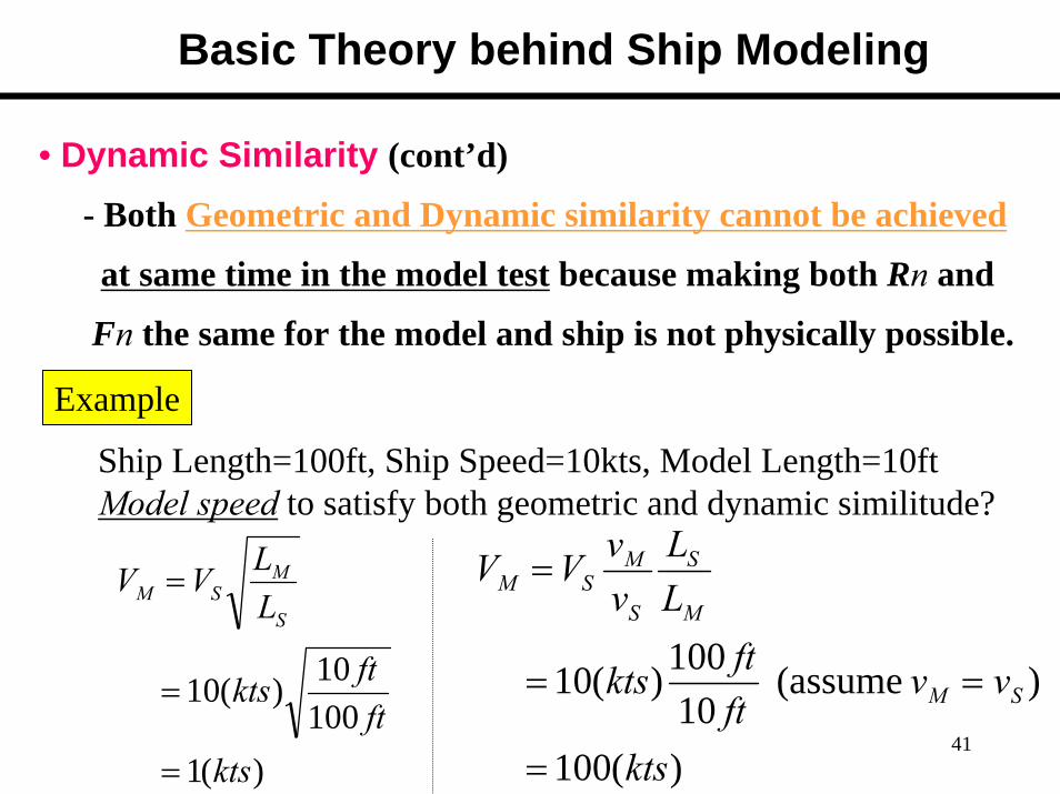
• Dynamic Similarity (cont’d)
- Both Geometric and Dynamic similarity cannot be achieved
at same time in the model test because making both Rn and
Fn the same for the model and ship is not physically possible.
)(1 10010)(10
ktsftftkts
LLVV
S
MSM
=
=
=
)(100
) (assume 10
100)(10
kts
vvftftkts
LL
vvVV
SM
M
S
S
MSM
=
==
=
Example
Ship Length=100ft, Ship Speed=10kts, Model Length=10ftModel speed to satisfy both geometric and dynamic similitude?

42
Basic Theory behind Ship Modeling
• Dynamic Similarity (cont’d)- Choice ?
· Make Fn the same for the model.· Have Rn different⇒ Incomplete dynamic similarity
- However partial dynamic similarity can be achieved by towing the model at the “corresponding speed”
- Due to the partial dynamic similarity, the following relations in forces are established.
WSWM CC =
VSVM CC ≠

43
Basic Theory behind Ship Modeling
• Corresponding Speeds
M
M
S
SnMnS gL
VgLVFF == ,
- Example :Ship length = 200 ft, Model length : 10 ftShip speed = 20 kts, Model speed towed ?
ktsktsV
LLV
LLVV
S
MSS
S
MSM
47.4 201201
/1
===
==
λ
(ft)L(ft/s)V
(ft)L(ft/s)V
M
M
S
S =
1kt.=1.688 ft/s

44
Basic Theory behind Ship Modeling• Modeling Summary
AWFAWVT CCKCCCCC +++=++= )1(
AMWMMFMTM CCKCC +++= )1(
)5.0*( 550
)(
)1(
2sSSTSTS
STS
ASWSSFSTS
VSCRVRhpEHP
CCKCC
ρ=⋅
=
+++=
AMFMTMWM CKCCC −+= − )1(FroudeExpansion
Measured in tank
)calculatedor (given, 0smooth) is Model( 0
)givenor Calculated .factor scale todue( d)(calculate ,
)//V ,( S
≠=
=
===
AS
AM
MS
FSFM
MMSnMnSWMWS
CC
KKCC
gLVgLFFCC
Q
Q
λ
1)
2)
3)